Model 20-28 VoIP Panel - IDA Coidaco.com/Manuals/20-28/20-28_voip_panel_180.pdf · Trunking Radio...
31
20-28 VoIP Remote Termination Panel Version 1.80 Printings Version 1.00: 7/27/2004 Version 1.01: 9/17/2004 Version 1.10: 2/15/2005 Version 1.11: 3/30/2005 Version 1.60: 4/22/2005 Version 1.70: 8/03/2006 Version 1.80: 11/09/2009
Transcript of Model 20-28 VoIP Panel - IDA Coidaco.com/Manuals/20-28/20-28_voip_panel_180.pdf · Trunking Radio...

20-28 VoIP
Remote Termination Panel
Version 1.80
Printings
Version 1.00: 7/27/2004 Version 1.01: 9/17/2004 Version 1.10: 2/15/2005 Version 1.11: 3/30/2005 Version 1.60: 4/22/2005 Version 1.70: 8/03/2006 Version 1.80: 11/09/2009

TABLE OF CONTENTS
SPECIFICATIONS ........................................................................................................................ 1
1.0 GENERAL DESCRIPTION .................................................................................................... 2 1.1 Description ................................................................................................................. 2 1.2 Capabilities and Features .......................................................................................... 2
2.0 INSTALLATION AND SETUP ............................................................................................... 3 2.1 Inspection ................................................................................................................... 3 2.2 Disassembly and Reassembly ................................................................................... 3 2.3 Installation Procedure ................................................................................................ 3 2.4 Radio Connection ....................................................................................................... 4 2.5 Ethernet Connections ................................................................................................. 5 2.6 Desk Microphone Connection .................................................................................... 5 2.7 Speaker Connection ................................................................................................... 5 2.8 Jumper and Test Point Settings .................................................................................. 6
3.0 OPERATION .......................................................................................................................... 7 3.1 General ...................................................................................................................... 7 3.2 Outputs ....................................................................................................................... 7 3.3 Local Control Option .................................................................................................. 7
4.0 PROGRAMMING PROCEDURES ......................................................................................... 8 4.1 Programming Parameters .......................................................................................... 8 4.2 Audio Adjustments ................................................................................................... 15 4.3 Backup/Restore ........................................................................................................ 16 4.4 Information/Status .................................................................................................... 17
5.0 CIRCUIT DESCRIPTION ..................................................................................................... 18 5.1 Power Supply ........................................................................................................... 18 5.2 Transmit Audio ......................................................................................................... 18 5.3 Receive Audio .......................................................................................................... 18 5.4 Outputs ..................................................................................................................... 18 5.5 Local Control ............................................................................................................ 19 5.6 Microprocessor ......................................................................................................... 19 5.7 Digital Signal Processor ........................................................................................... 19 5.8 Ethernet Interface ..................................................................................................... 19 5.9 20-28 VoIP Interface Board ...................................................................................... 19
APPENDIX A - RADIO INTERFACES ....................................................................................... 20 Conventional Binary Interface ......................................................................................... 20 Trunking Radio Interface ................................................................................................. 21 Additional Radio Interfaces ............................................................................................. 21
PARTS LISTS ............................................................................................................................. 22
SCHEMATICS ............................................................................................................................ 27
INSTALLATION DIAGRAMS ..................................................................................................... 28
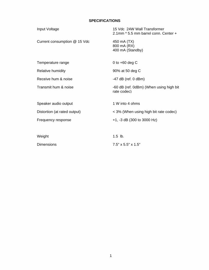
SPECIFICATIONS
Input Voltage 15 Vdc 24W Wall Transformer 2.1mm * 5.5 mm barrel conn. Center +
Current consumption @ 15 Vdc
450 mA (TX) 800 mA (RX) 400 mA (Standby)
Temperature range 0 to +60 deg C
Relative humidity 90% at 50 deg C
Receive hum & noise -47 dB (ref. 0 dBm)
Transmit hum & noise -60 dB (ref. 0dBm) (When using high bit rate codec)
Speaker audio output 1 W into 4 ohms
Distortion (at rated output) < 3% (When using high bit rate codec)
Frequency response +1, -3 dB (300 to 3000 Hz)
Weight 1.5 lb.
Dimensions 7.5" x 5.5" x 1.5"
1
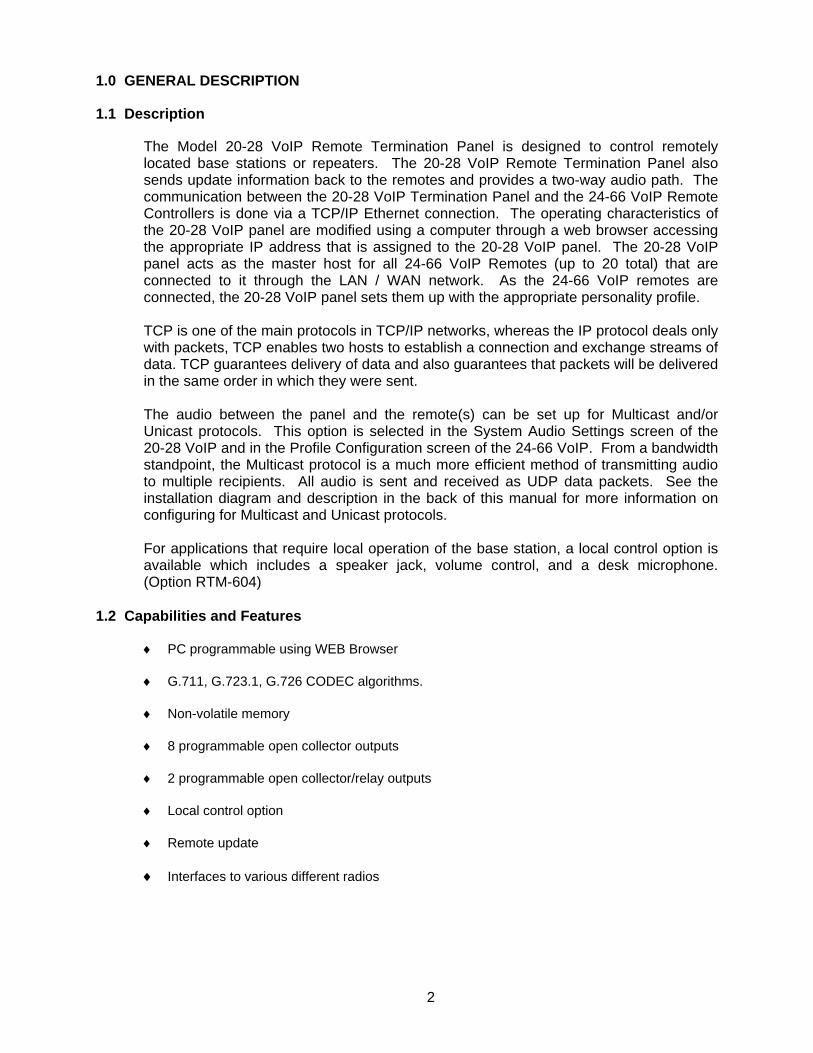
1.0 GENERAL DESCRIPTION
1.1 Description
The Model 20-28 VoIP Remote Termination Panel is designed to control remotely located base stations or repeaters. The 20-28 VoIP Remote Termination Panel also sends update information back to the remotes and provides a two-way audio path. The communication between the 20-28 VoIP Termination Panel and the 24-66 VoIP Remote Controllers is done via a TCP/IP Ethernet connection. The operating characteristics of the 20-28 VoIP panel are modified using a computer through a web browser accessing the appropriate IP address that is assigned to the 20-28 VoIP panel. The 20-28 VoIP panel acts as the master host for all 24-66 VoIP Remotes (up to 20 total) that are connected to it through the LAN / WAN network. As the 24-66 VoIP remotes are connected, the 20-28 VoIP panel sets them up with the appropriate personality profile. TCP is one of the main protocols in TCP/IP networks, whereas the IP protocol deals only with packets, TCP enables two hosts to establish a connection and exchange streams of data. TCP guarantees delivery of data and also guarantees that packets will be delivered in the same order in which they were sent. The audio between the panel and the remote(s) can be set up for Multicast and/or Unicast protocols. This option is selected in the System Audio Settings screen of the 20-28 VoIP and in the Profile Configuration screen of the 24-66 VoIP. From a bandwidth standpoint, the Multicast protocol is a much more efficient method of transmitting audio to multiple recipients. All audio is sent and received as UDP data packets. See the installation diagram and description in the back of this manual for more information on configuring for Multicast and Unicast protocols. For applications that require local operation of the base station, a local control option is available which includes a speaker jack, volume control, and a desk microphone. (Option RTM-604)
1.2 Capabilities and Features
♦ PC programmable using WEB Browser
♦ G.711, G.723.1, G.726 CODEC algorithms.
♦ Non-volatile memory
♦ 8 programmable open collector outputs
♦ 2 programmable open collector/relay outputs
♦ Local control option
♦ Remote update
♦ Interfaces to various different radios
2

2.0 INSTALLATION AND SETUP
2.1 Inspection
Please refer to the checklist packed with the 20-28 VoIP in order to become familiar with the unit and to insure that everything ordered has been received. In the event a part is missing from the checklist, please call the Customer Services Department at 1-701-280-1122. This unit was thoroughly inspected before leaving the factory. If the outer package appears damaged, please inspect the unit for possible damage immediately. Any dents, scratches, or marks suggest rough handling in shipping. Please notify the shipper if you find any indications of mishandling. If there are any concerns about the condition of the 20-28 VoIP when it is received, please don't hesitate to call the Customer Services Department.
2.2 Disassembly and Reassembly
When performing the alignment procedure or making changes to the jumpers on the 20-28 VoIP, it may be necessary to remove the printed circuit board from the case. This is accomplished by removing the two black screws from the front of the 20-28 VoIP and removing the front panel. Remove the top cover by sliding it off the 20-28 VoIP. Since the printed circuit board contains sensitive circuitry, be sure to take the necessary precautions against static discharge. To reassemble the 20-28 VoIP, replace the top cover and the front panel, making sure the front and back panels are seated properly with the case. Replace the two black screws but do not over-tighten them.
2.3 Installation Procedure
This section provides a basic step-by-step installation procedure for the 20-28 VoIP. Refer to sections 2.4 - 2.8 for detailed installation information. Refer also to the 20-28 VoIP installation diagram in the back of this manual. Detailed information on adjusting the 20-28 VoIP audio levels can be found in section 4.0 Adjustment Procedures. 1. The system should initially be set up and tested on the bench. Use only one remote
at first. Additional remotes can be added later.
2. Connect the 20-28 VoIP to the base station radio. Be sure to program the base station radio as required.
3. Set the 20-28 VoIP jumpers as required.
4. Program the 20-28 VoIP and the remote to allow the remote to control the base station radio as desired. See the programming procedure for the 24-66 VoIP and for the 20-28 VoIP.
3

2.3 Installation Procedure (cont.)
5. Connect the optional wall transformer power supply to power connector on the back of the 20-28 VoIP. If power is being supplied to the 20-28 VoIP from the radio, make sure the radio’s switched B+ output can supply the necessary current. Also, JP6 must be in the correct position. Position AB is for power from radio and position BC is for power from the optional wall transformer.
6. Connect the TCP/IP Ethernet connection to appropriate connector on the back of the 20-28 VoIP. If the connection being used is also to be shared with an existing computer, the computer can be connected to the computer Ethernet connector on the back of the 20-28 VoIP. This allows the 20-28 VoIP and the computer to share one network cable. The green link LED on the Ethernet connector should turn on showing a connection to the network. Refer also to the 20-28 VoIP installation diagram in the back of this manual.
7. Connect a 24-66 VoIP remote to the network. The 20-28 VoIP panel will configure the remote with the appropriate profile.
8. Receive audio from the base station radio should now be heard at the remote.
9. Press PTT on the remote. The remote should key the base station radio reliably.
10. The remote should also be able to control radio functions such as change channels or systems and groups on the base station radio if the system is configured for that.
11. If the local control option is installed in the 20-28 VoIP, connect the desk microphone to the 20-28 VoIP and press the PTT button to verify that the radio transmits.
12. If the local control option is installed in the 20-28 VoIP, connect a 4 ohm speaker to the 20-28 VoIP. Remote audio should be heard in the speaker when PTT on the remote is pressed. Adjust the volume control on the front of the 20-28 VoIP as desired.
13. Program any additional remotes as required. Generally, they should be programmed the same as the first remote. See the programming procedure for the 24-66 VoIP and for the 20-28 VoIP.
14. Connect additional remotes to the network
15. Adjust the transmit and receive levels of the remotes as required. Audio from all remotes should be set to the same level. Refer to Section 4.2 for Audio Adjustments.
2.4 Radio Connection
The DB-25 connector labeled "RADIO" on the back of the 20-28 VoIP is used to interface the 20-28 VoIP to a base station radio. For the pin functions on the DB-25 connector, refer to the 20-28 VoIP installation diagram in the back of this manual. In addition, Appendix A contains interface information for connecting the 20-28 VoIP to radios.
4

2.5 Ethernet Connections
The 20-28 VoIP allows Remote Control of a base station via an Ethernet LAN. A computer can also be connected to a remote that is on the same LAN to allow the computer access to the network without the need for a hub. The Ethernet connectors are found on the back of the 20-28 VoIP. The Ethernet cable should be a standard cable that is available anywhere that telephone and computer accessories are sold. Refer also to the 20-28 VoIP installation diagram in the back of this manual.
2.6 Desk Microphone Connection
If the local control option is installed in the 20-28 VoIP, the desk microphone should be connected to the modular jack labeled "LOCAL MIC" on the front of the 20-28 VoIP. The connections that the local microphone jack provides are detailed in Figure 1.
Figure 1
2.7 Speaker Connection
If the local control option is installed in the 20-28 VoIP, a speaker can be connected to the 20-28 VoIP to allow audio to be heard. A 4 ohm speaker (supplied by the user) should be connected to the speaker plug supplied with the 20-28 VoIP. The speaker plug should then be inserted into the jack labeled "SPEAKER JACK" on the back of the 20-28 VoIP.
5

2.8 Jumper and Test Point Settings
The 20-28 VoIP has a test point, number of jumpers, and switches located on the INTERFACE BOARD that controls the operation of the 20-28 VoIP. The jumpers and their settings are described below.
SW1 Position A is for logic level serial interface.
Position B is for RS485 level serial interface.
JP 5 IN for LOW TX Audio impedance.
OUT for HIGH TX Audio impedance.
JP 6 * AB for POWER from radio
BC for Power from External Wall Transformer
JP 7 AB for open collector output 9.
BC for relay output on output 9.
JP 8 AB for open collector output 10.
BC for relay output on output 10.
* If using POWER from the radio and not the EXTERNAL WALL TRANSFORMER, make sure the radio can provide the current needed by the 20-28 VoIP. The default is BC for POWER from the WALL TRANSFORMER.
TP 4 (Test Point 4) allows the panel's network address (including subnet and gateway) to be reset to factory defaults.
To begin, disconnect (or verify disconnection of) power. With power removed, connect a jumper wire between (ground) the housing of the RJ45 jack (J1 or J6) and TP4. Once this connection is made, apply power. With power applied, the LED on the main board D6 should turn on, turn off, and then turn on again. At this point, the network address has been reset and the panel is rebooting, so remove the jumper wire between the RJ45 jack and TP4. The panel should finish rebooting. The network address of the panel is now:
IP Addresss: 10.0.0.200 Subnet Mask: 255.255.255.0
Gateway: 10.0.0.40
6

3.0 OPERATION
3.1 General
Once the installation is complete, the 20-28 VoIP panel will communicate with the 24-66 VoIP remotes via Ethernet TCP/IP protocol. The remotes will be able to control the functions of the radio such as transmit and channel selection, as well as receive and transmit audio.
3.2 Outputs
The 20-28 VoIP contains 10 open collector outputs. Two of these outputs, outputs 9 and 10, can also be switched to relay outputs. The outputs are available as general purpose outputs and can be programmed as active high or active low and also as timed outputs. The outputs are controlled by the remote, which can enable or disable any number of outputs with a single update sequence.
3.3 Local Control Option
The local control option allows local control of the base station radio. This option provides a speaker jack, volume control, a desk microphone, and other associated circuitry. When PTT is pressed on the desk microphone, the 20-28 VoIP will key the base station radio. Audio from the desk microphone will be passed to the base station radio for transmission and will also be sent to the network so that the remote users can hear the transmission. If the intercom switch on the front panel of the 20-28 VoIP is depressed, the 20-28 VoIP will not key the base station radio when PTT is pressed on the desk microphone. Instead, the audio from the desk microphone will only be sent to the network to allow the local user to intercom to the remotes. A 4 ohm speaker can be connected to the speaker jack to allow the local user to hear audio from a remote that is transmitting. Audio from a remote in intercom mode will also be heard through the speaker. Receive audio from the base station radio can also be passed to the speaker. This allows the local user to hear transmissions from other radios through the local speaker instead of through the speaker of the base station radio. The volume control on the front of the 20-28 VoIP allows the local user to adjust the speaker volume to a comfortable listening level.
7

4.0 PROGRAMMING PROCEDURES
All audio and configuration adjustments are done using a web browser directed at the IP Address that is assigned to the 20-28 VoIP. The following will explain the adjustment procedure for the 24-66 VoIP. Most audio levels are factory preset and will, in most cases, not need adjustment. All of the audio adjustment are accessible from a computer using a web browser. The default address is 10.0.0.200 with the subnet of 255.255.255.0. The IP address and the subnet address will need to be changed to connect to your network. The user name is “admin” and the default password is ”idacorp”. Once you logon you should change the password to something else to protect your system. If you are configuring multiple 20-28 VoIP Panels or 24-66 VoIP Remotes, you may need to reset the computer NIC card or restart the computer if the next 24-66 VoIP your computer is connected to does not respond. The following will explain the adjustment procedure for the 24-66 VoIP.
4.1 Programming Parameters
All of the programming and audio parameters are accessible through a WEB browser on a PC that is on the network accessing the IP Address that is assigned to the 20-28 VoIP. The default IP Address is 10.0.0.200. The default account name is admin. The default password is idacorp. It is suggested that the password be changed to protect the system. Refer to the Help screens under each of the configuration parameter headers for more information on programming options. Network The screen below shows the Network Configuration Parameters.
8

4.1 Programming Parameters (cont.) Radio The screen below shows the Setup Radio tab.
Radio The screen below shows the Binary Channel Setup tab.
9

4.1 Programming Parameters (cont.) Radio The screen below shows the Radio I/O tab.
Output The screen below shows the Output Parameters.
4.1 Programming Parameters (cont.)
10

Action The screen below shows the Action Parameters.
Channel The screen below shows the Channel Parameters.
11

4.1 Programming Parameters (cont.) Remote Configuration The screen below shows the Remote Configuration.
Remote The screen below shows the Remote Button Parameters for Profile 1.
12

4.1 Programming Parameters (cont.) Remote The screen below shows the Miscellaneous Configuration for profile 1.
Remote The screen below shows the Remote Tone Configuration for profile 1.
13
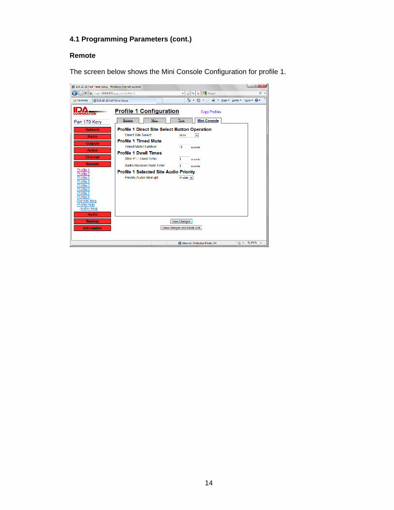
4.1 Programming Parameters (cont.) Remote The screen below shows the Mini Console Configuration for profile 1.
14

4.2 Audio Adjustments
Audio The screen below shows the System Audio Configuration tab.
Audio The screen below shows the Local Audio Configuration tab.
15

4.3 Backup/Restore
The screen below shows the Backup / Restore feature.
16

4.4 Information/Status
The screen below shows the Local Information tab.
Information The screen below shows the Remote Information tab.
17

5.0 CIRCUIT DESCRIPTION
The 20-28 VoIP consists of two circuit boards. One circuit board is the 20-28 VoIP Ethernet/Audio platform. The other circuit board is the 20-28 VoIP Interface board used to make all of the radio and power connections.
5.1 Power Supply
Power is supplied to the 20-28 VoIP via the optional 15VDC wall transformer or the switched B+ output from the radio. The polarity of the connector must be correct. It is connected at J18 on the 20-28 VoIP Interface board. It is sent to J10 on the 20-28 VoIP Interface board, then to J10 on the 20-28 VoIP board. From J10 the power is routed through a diode D7 and a 1 amp fuse F1. Diode D7 prevents a reverse polarity from harming the 20-28 VoIP. Power is fed into voltage regulator U18. The output voltage of U18 is set to 10.5. This 10.5 Vdc through a diode D4 drives the audio section of the 20-28 VoIP. It is also fed into voltage regulator U19 and U20. The output voltage of U19 is set to 3.3 Vdc and this 3.3 Vdc is also fed into voltage regulator U16. The output voltage of U16 is set to 1.5 Vdc. The output voltage of U20 is set to 2.5 Vdc. The 3.3 Vdc, 2.5 vdc, and the 1.5 Vdc powers the digital section of the 20-28 VoIP.
5.2 Transmit Audio
Transmit audio UDP packets from the Ethernet interface section are passed to the microprocessor U8 for decoding. The decoded digital audio is then sent to the DSP U10. The DSP then converts the digital audio to analog and adjusts the level out. The audio is passed to pin 4 of J3 to the 20-28 VoIP Interface board where it is sent to pin 21 of the radio interface connector P1. The audio is also fed into the speaker driver U3. U3 and its associated circuitry is a wide band audio amplifier set to have a gain of 36 dB. The output of the speaker driver goes to pin 7 of J4 and sent to the 20-28 Interface board where it is sent to the speaker jack J16.
5.3 Receive Audio
Receive audio from the radio comes from pin 1 of the radio interface connector P1. It is then passed to pin 4 of J5 on the 20-28 VoIP board. The audio is biased by resistors R126 and R136. The audio then passed through the DSP U10 where it is converted to digital. The digital audio is then sent to the microprocessor to be assembled in to UDP packets. The UDP Packets are then passed to the Ethernet section.
5.4 Outputs
The output states are controlled by U17 on the20-28 VoIP board. The outputs are then sent to the open collector output drivers U2 and U3 on the 20-28 VoIP Interface Board via J13. Outputs 9 and 10 are optionally connected to relay outputs by JP7 and JP8.
18

5.5 Local Control
The local control is done through the 20-28 VoIP Interface board. The local desk microphone is connected to J15, which is connected to J5 passing all connections directly to the DSP, U10 on the 20-28 VoIP board where the audio, PTT and monitor functions are processed. The intercom switch is connected to J4 which connects to the DSP. The local speaker audio is sent from the DSP to the audio amplifier U3 and then sent to J4 on the 20-28 VoIP Interface board where it is sent to J16, the speaker jack.
5.6 Microprocessor
The Net+ARM 7520B MCU U8 provides the network interface functions and provides the platform for the application code. Integrated peripherals include a 10/100 Ethernet MAC, two serial ports, and numerous general-purpose I/O pins. An RTOS and a TCP/IP stack are included along with drivers for the internal peripherals.
5.7 Digital Signal Processor
The DSP U10 provides the audio processing functions. This DSP has six audio inputs, four audio outputs, a single Sigma-Delta CODEC, and an audio multiplexor to connect the CODEC to one audio input and one audio output. It also has numerous general-purpose I/O pins and a host interface. The DSP firmware comes pre-programmed in ROM and the functions provided can be controlled by the host CPU U8 through the host interface. The DSP firmware provides the following standard CODEC algorithms: G.711, G.723.1, and G.726.
5.8 Ethernet Interface
The Ethernet interface consists of a three port 10/100 Base-TX Switch U4. One port is connected externally to the LAN and the second port is connected externally to a computer to allow the computer access to the LAN. The third port is connected internally to the Ethernet port of the NET+ARM MCU U8. LEDs integrated into the Ethernet connectors will provide Connect and Activity status. The Ethernet port for connecting to the PC will be cross-wired to allow straight-through cables to be used on both ports.
5.9 20-28 VoIP Interface Board
The 20-28 VoIP Interface board provides the connections between the 20-28 VoIP board and the radio, power, and local control components. Items not covered thus far are described here. P1 pin 1 is the RX audio input. It is connected to J4 pin 5 on the 20-28 VoIP board where it goes to the DSP. Transmit audio comes from the DSP and goes to J3 pin 4 on the 20-28 VoIP Interface board and goes through impedance resistors to P1 pin 21. P1 pin 25 is the COR input. It goes through Q3 to J2 pin 2 on the 20-28 VoIP board then to the DSP. P1 pin 9 is the transmit indicator input. It goes through Q4 then to J11 pin 2 on the 20-28 VoIP board then to the DSP. P1 pins 2 and 3 are serial data in and out. The signals are selectable for RS485 or logic level by SW1. The signals go to J8 pins 3 & 4 on the 20-28 VoIP board then to the Net+ARM MCU.
19

APPENDIX A - RADIO INTERFACES
This appendix contains instructions for interfacing the 20-28 VoIP panel for various radio applications.
Conventional Binary Interface
The following steps outline the procedure for interfacing a conventional radio requiring binary control signals to the 20-28 VoIP:
1. Identify which radio functions should be controlled by the 20-28 VoIP. The available functions of the conventional binary interface on the 20-28 VoIP are described below.
• COR: Control signal from the radio that is active while receiving audio. • PTT: Control signal from the 20-28 VoIP that is active when the radio should
transmit. • Channel Control Outputs: Control signals from the 20-28 VoIP to change
the channel on the radio through binary output patterns. The number of outputs used for channel control can be programmed from 1 to 8. Consult the table below for the number of outputs required. Note that output #1 will always be the least significant output. Outputs #2 to #8 not used for channel control are available as user defined outputs.
Number of Channel Outputs Max. # of Channels
1 2 2 4 3 8 4 16 5 32 6 64 7 128 8 255
• User Defined Outputs: Several additional outputs are available for controlling other radio functions.
2. Construct the cable end that will connect to the 20-28 VoIP's P1 Radio
connector. A generic cable kit is available from IDA Corporation (Part No. 102-OPT371). The following table lists the connections required to a DB25 male connector for each 20-28 VoIP function.
Connection Function Pin #1 RX Audio Pin #7 Ground Pin #20 +13.8 Vdc Pin #21 TX Audio Pin #25 COR Output #1-7 User-programmable
Channel Output Pattern
Output #8 User Defined Output #9 PTT Output #10 User Defined
20

Conventional Binary Interface (cont.)
3. Connect the other end of the cable to the radio. This may require modifications to the radio. Consult the radio manual for details.
4. Configure the jumpers on the 20-28 VoIP based on the system requirements. Check the audio level adjustments.
Trunking Radio Interface
The 20-28 VoIP may also be interfaced to a trunking radio for transmit and receive only with no channel or scan control. Full featured, radio model specific interfaces are available, contact the factory. In order to provide handshake tones in a trunking application, it is necessary to utilize the TRANSMIT INDICATOR input on the 20-28 VoIP. The TRANSMIT INDICATOR input is on Pin 9 of P1. The 20-28 VoIP must also be programmed for the correct TX Active HI / LOW polarity under the RADIO PARAMETERS screen as shown above. It needs to remain active throughout the entire transmission. For conventional applications it should be set to IGNORE.
Additional Radio Interfaces
For radio specific interfaces, refer to the Radio Configuration Parameters screen of the 20-28 VoIP or contact the factory for the availability of updates for additional radio interfaces.
21
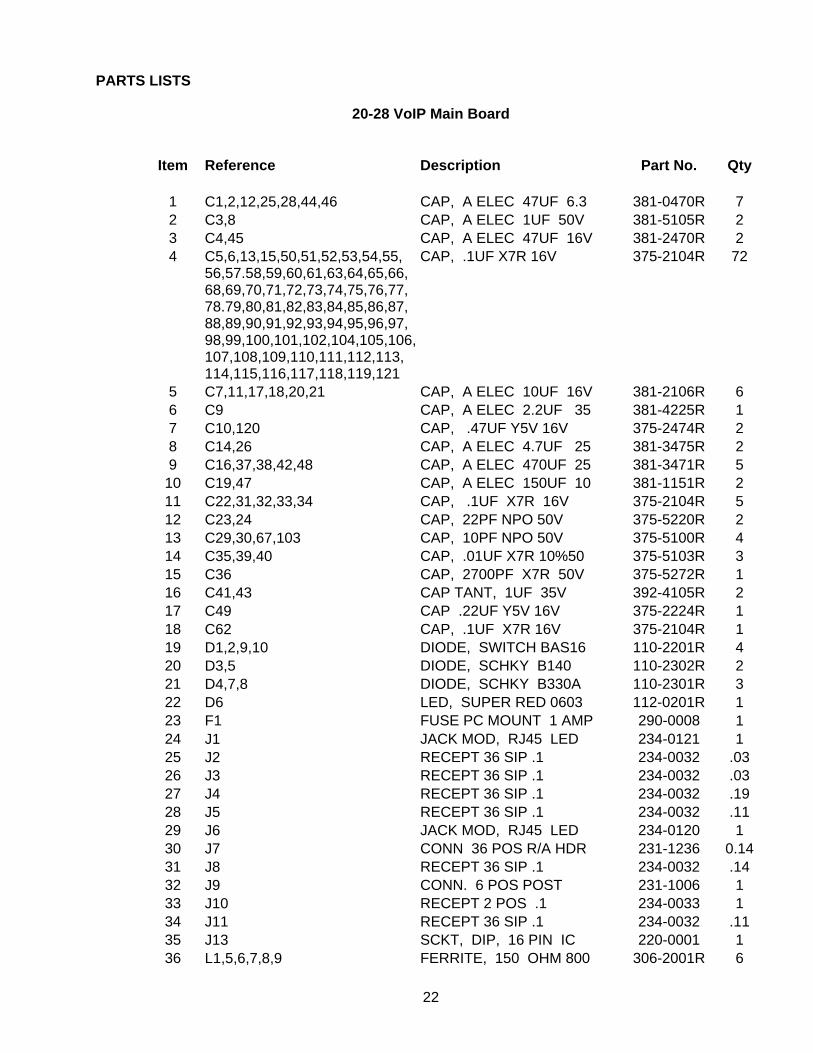
PARTS LISTS
20-28 VoIP Main Board
Item Reference Description Part No. Qty
1 C1,2,12,25,28,44,46 CAP, A ELEC 47UF 6.3 381-0470R 7 2 C3,8 CAP, A ELEC 1UF 50V 381-5105R 2 3 C4,45 CAP, A ELEC 47UF 16V 381-2470R 2 4 C5,6,13,15,50,51,52,53,54,55,
56,57.58,59,60,61,63,64,65,66, 68,69,70,71,72,73,74,75,76,77, 78.79,80,81,82,83,84,85,86,87, 88,89,90,91,92,93,94,95,96,97, 98,99,100,101,102,104,105,106,107,108,109,110,111,112,113, 114,115,116,117,118,119,121
CAP, .1UF X7R 16V 375-2104R 72
5 C7,11,17,18,20,21 CAP, A ELEC 10UF 16V 381-2106R 6 6 C9 CAP, A ELEC 2.2UF 35 381-4225R 1 7 C10,120 CAP, .47UF Y5V 16V 375-2474R 2 8 C14,26 CAP, A ELEC 4.7UF 25 381-3475R 2 9 C16,37,38,42,48 CAP, A ELEC 470UF 25 381-3471R 5
10 C19,47 CAP, A ELEC 150UF 10 381-1151R 2 11 C22,31,32,33,34 CAP, .1UF X7R 16V 375-2104R 5 12 C23,24 CAP, 22PF NPO 50V 375-5220R 2 13 C29,30,67,103 CAP, 10PF NPO 50V 375-5100R 4 14 C35,39,40 CAP, .01UF X7R 10%50 375-5103R 3 15 C36 CAP, 2700PF X7R 50V 375-5272R 1 16 C41,43 CAP TANT, 1UF 35V 392-4105R 2 17 C49 CAP .22UF Y5V 16V 375-2224R 1 18 C62 CAP, .1UF X7R 16V 375-2104R 1 19 D1,2,9,10 DIODE, SWITCH BAS16 110-2201R 4 20 D3,5 DIODE, SCHKY B140 110-2302R 2 21 D4,7,8 DIODE, SCHKY B330A 110-2301R 3 22 D6 LED, SUPER RED 0603 112-0201R 1 23 F1 FUSE PC MOUNT 1 AMP 290-0008 1 24 J1 JACK MOD, RJ45 LED 234-0121 1 25 J2 RECEPT 36 SIP .1 234-0032 .03 26 J3 RECEPT 36 SIP .1 234-0032 .03 27 J4 RECEPT 36 SIP .1 234-0032 .19 28 J5 RECEPT 36 SIP .1 234-0032 .11 29 J6 JACK MOD, RJ45 LED 234-0120 1 30 J7 CONN 36 POS R/A HDR 231-1236 0.14 31 J8 RECEPT 36 SIP .1 234-0032 .14 32 J9 CONN. 6 POS POST 231-1006 1 33 J10 RECEPT 2 POS .1 234-0033 1 34 J11 RECEPT 36 SIP .1 234-0032 .11 35 J13 SCKT, DIP, 16 PIN IC 220-0001 1 36 L1,5,6,7,8,9 FERRITE, 150 OHM 800 306-2001R 6
22

37 L3 POWER IND, 47.00uH 306-3001R 1 38 L4 POWER IND, 33.00uH 306-3002R 1 39 P1 HDR 14 POS .1 X .1 231-1076 1 40 R1 RECEPT 36 SIP .1 X2 234-0032 .06 41 R2,3,18,19,21,22,23,25,26,35,
49,113,116,118,119,130,131, 133
RES, 49.9 1% 1/16W 322-49R9R 18
42 R4,5 RES, 2K 5% 1/10W 323-1202R 2 43 R7,10,13,30,48,51,52,53,54,56,
58, 71,76,80,83,86,107,108,111,112 120,125,132,134
RES, 10K 5% 1/10W 323-1103R 23
44 R9,12,14,15,55,78,79,81,82,98,105,106,115,123,124,128
RES, 0 5% 1/10W 323-0000R 13
45 R11,47,122 RES, 10 5% 1/10W 323-1100R 3 46 R17,20 RES, 100 1% 1/16W 322-1000R 2 47 R32,33,37,39,40,41,42,44,45,46 RES, 33 5% 1/10W 323-1330R 10 48 R34,38,43 RES, 820 5% 1/10W 323-1821R 3 49 R36,61,62,63,64,65,66,89,95,96
97,99,101,102,103,104,109,127129,136
RES, 1K 5% 1/10W 323-1102R 20
50 R50 RES, 499K 1% 1/16W 322-4993R 1 51 R60 RES, 56 5% 1/10W 323-1560R 1 52 R67 RES, 10M 5% 1/10W 323-1106R 1 53 R68 RES, 9.31k 1% 1/4W 326-9311R 1 54 R69 RES, 7.87k 1% ¼ W 326-7871 1 55 R70 RES, 7.15K 1% 1/4W 326-7151R 1 56 R72 RES, 300 5% 1/10W 323-1301R 1 57 R73 RES, 1k 1% 1/4W 326-1001R 1 58 R74,75 RES, 75K 5% 1/10W 323-1753R 2 59 R77 RES, 0 5% 1/10W 323-0000R 1 60 R90 RES, 2.7K 5% 1/10W 323-1272R 1 61 R94 RES, 1M 1% 1/16W 322-1004R 1 62 R110 RES, 3.01K 1% 1/16W 322-3011R 1 63 R121 RES, 1 5% 1/10W 323-11R0R 1 64 R126 RES, 620 5% 1/10W 323-1621R 1 65 U1 IC, 24LC256 131-1060 1 66 U2 IC, MCP3221A5T-I/OT 131-5001 1 67 U3 IC, TPA1517DWPR 131-1061 1 68 U4 IC, KS8993 131-2009 1 69 U5,15 IC, SN74AHC1GO8DBVR 131-5002 2 70 U6 IC, TC1270TERCT-ND 131-5003 1 71 U7 IC, SN74AHC1GO8DBVR 131-5002 1 72 U8 IC, NS7520B-1-C55 131-6000 1 73 U9,14 IC, HY57V161610DTC-7 131-1064 2 74 U10 IC, VP101X12BQC-1 131-2010 1 75 U11 IC, MAX3232ESE 131-1062 1 76 U12 IC, SN74LVC1GU04DBVR 131-5005 1 77 U13 IC, AM29LV800BT120 131-1063 1 78 U16 IC, LP3984IMF-1.5 131-5004 1 79 U17 IC, XC9572XL-10PC44C 131-3010 1
23

80 U18 IC, LM2673S-ADJ 131-4001 1 81 U19 IC, LM2673S-3.3 131-4002 1 82 U20 IC, LM1086CS-5.0 131-4003 1 83 U21 IC, LM1086CS-2.5 131-4004 1 84 Y2 CRY, 18.432 MHZ 20PF 305-0101R 1 85 Y3 CRY, 25.000MHZ 18PF 305-0103R 1 86 Y4 CRY, 4.096MHA 20PF 305-0102R 1 87 00 PC BD, VoIP RMT MAIN 900-0291 1
24

PARTS LISTS (Cont.)
20-28 VoIP Panel Interface Board
Item Reference Description Part No. Qty
1 0 PEM 4-40 X 5/8 THRD 200-119 4 2 0 PC BOARD VIOP PANEL 900-0300 1 3 C1,2 CAP, .1UF X7R A6V 375-2104R 2 4 J13 POST, MACHINED 9 PIN 231-1088 2 5 J3,4,8,11,17A HDR 16 POS .100 POST 231-3116 1.06 6 J10 CONN, 2 POS .1 LOCK HDR 234-0019 1 7 J18 CONN, R/A POWER 234-0014 1 8 JP5,6,7,8 CONN 36 POS BKWY HDR 231-1040 .30 9 K1,2 RELAY, PC MOUNT MINI 700-0010 2
10 P1 NUT, HEX 4-40 199-0010 2 11 P1 SCW, 4-40 X ¼ PHLP 199-3055 2 12 P1 CONN DB25 R/A PC MNT 231-0004 1 13 Q1,2,3,4 TRANS, 2N7002 180-1003R 4 14 R2,3 RES, 100 OHM 5% 1/8 W 321-1101R 2 15 R20 RES, 510 OHM 5% 1/8 W 321-1511R 1 16 R1,17,18,19 RES, 10K OHM 5% 1/10 W 323-1103R 4 17 R5 RES, 300 OHM 5% 1/10 W 323-1301R 1 18 R4,6,7,8,9,10,11,12,13,14,15 RES, 4.7K OHM 5% 1/10 W 323-1472R 11 19 SW1 SWITCH, DPDT DIP 6PS 611-0048 1 20 U2,3 IC, ULN2003A 131-1075 2 21 U1 IC, DS1487M 131-1076 1
20-28 VoIP Panel Interface Board Local Control Option
1 J15 JACK, MOD 4 POS SIDE 231-0021 1 2 J2,5,17A,17B HDR 16 POS .100 POST 231-3116 .44 3 J16 JACK, SPKR PNL MNT 234-0091 1 4 R16 POT, 50K SLIDE/AUDTAP 340-0003 1 5 SW2 SWITCH, SUB MIN PUSH PC 611-0044 1
25
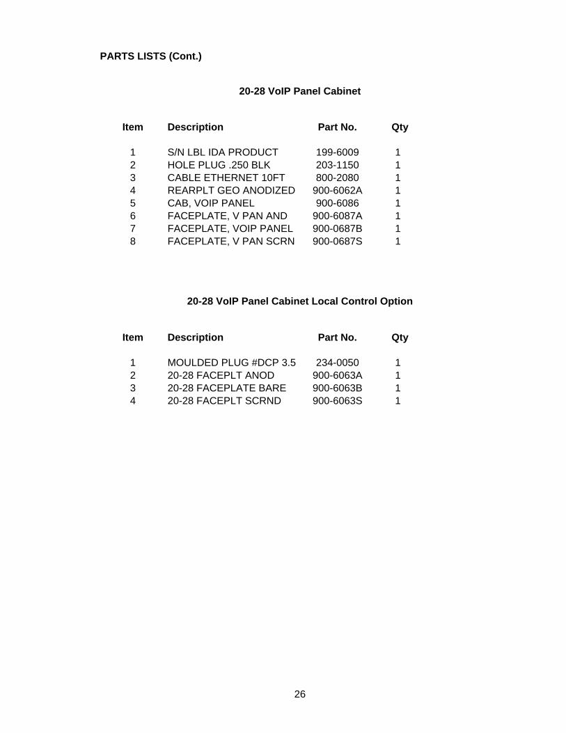
PARTS LISTS (Cont.)
20-28 VoIP Panel Cabinet
Item Description Part No. Qty
1 S/N LBL IDA PRODUCT 199-6009 1 2 HOLE PLUG .250 BLK 203-1150 1 3 CABLE ETHERNET 10FT 800-2080 1 4 REARPLT GEO ANODIZED 900-6062A 1 5 CAB, VOIP PANEL 900-6086 1 6 FACEPLATE, V PAN AND 900-6087A 1 7 FACEPLATE, VOIP PANEL 900-0687B 1 8 FACEPLATE, V PAN SCRN 900-0687S 1
20-28 VoIP Panel Cabinet Local Control Option
Item Description Part No. Qty
1 MOULDED PLUG #DCP 3.5 234-0050 1 2 20-28 FACEPLT ANOD 900-6063A 1 3 20-28 FACEPLATE BARE 900-6063B 1 4 20-28 FACEPLT SCRND 900-6063S 1
26

5
5
4
4
3
3
2
2
1
1
D D
C C
B B
A A
5V3.3V
3.3V
5V
13.8V
13.8V
13.8V
13.8V
3.3V
5V
5V
3.3V
3.3V
5V
3.3V
13.8V
REV BY DATE DESCRIPTION
1345 MAIN AVEFARGO, ND 58103701-280-1122FAX - 218-233-1886
BY: DATE: SCALE:TITLE:
PART NO: SHEET SIZE:UNITS: INCHES
REV BY DATE DESCRIPTION
1345 MAIN AVEFARGO, ND 58103701-280-1122FAX - 218-233-1886
BY: DATE: SCALE:TITLE:
PART NO: SHEET SIZE:UNITS: INCHES
REV BY DATE DESCRIPTION
1345 MAIN AVEFARGO, ND 58103701-280-1122FAX - 218-233-1886
BY: DATE: SCALE:TITLE:
PART NO: SHEET SIZE:UNITS: INCHES
VOIP BOARD
VOIP BOARD
VOIP BOARD
A CA 12/12/04 Initial Release
CA 12/12/04
900-0300
VOIP Panel
B MA 2/24/05 Added Test Point 4
R154.7KR154.7K
1J17AJ17A
123
J16
SPEAKER
J16
SPEAKER
3
1
2
Q22N7002Q22N7002
3
1
2
Q32N7002Q32N7002
TP4TPTP4TP
R2 100R2 100
1
2
3
4
5
678910
11
12131415
16
J13J13
R64.7KR64.7K
8
15
7
14
6
13
5
12
4
11
3
10
2
9
1
16171819
2021
222324
25
P1
DB25
P1
DB25R124.7KR124.7K
3J17B
VOIP BOARD
J17B
VOIP BOARD
R19 10KR19 10K
R3 100R3 100
C1.1uFC1.1uF
C2
.1uF
C2
.1uF
2J2
VOIP BOARD
J2
VOIP BOARD
56
4SW2B
SWPUSH
SW2B
SWPUSH
R74.7KR74.7K
R144.7KR144.7K
R1710KR1710K
1J10AJ10A
R44.7kR44.7k
1
2
3
JP6JP6
R84.7KR84.7K
1B1
2B2
3B3
4B4
5B5
6B6
7B7
E8
CO
M9
7C 10
1C 16
2C 15
3C 14
4C 13
5C 12
6C 11
U2ULN2003U2ULN2003
51
1038
K1RELAY SPDT
K1RELAY SPDT
123
J18
POWER
J18
POWER
56
4
SW1B
SWPUSH
SW1B
SWPUSH
23
1SW2A
SWPUSH
SW2A
SWPUSH
1B1
2B2
3B3
4B4
5B5
6B6
7B7
E8
CO
M9
7C 10
1C 16
2C 15
3C 14
4C 13
5C 12
6C 11
U3ULN2003U3ULN2003
RO1
RE2
DE3
DI4 GN
D5
A 6
B 7
VCC
8
U1DS1487MU1DS1487M
R5300R5300
R94.7KR94.7K
3
1
2
Q42N7002Q42N7002
1
2
3
4
5
6
7
J4J4
R20 510R20 510
3J10B
VOIP BOARD
J10B
VOIP BOARD
1
2
3
JP8JP8
R1810KR1810K
2
3
1
4J5J5
R134.7KR134.7K
13
2R16448UD4503BDNR16448UD4503BDN
R104.7KR104.7K
1
2
3
JP7JP7
3
1
2
Q12N7002Q12N7002
23
1SW1A
SWPUSH
SW1A
SWPUSH
2
3
1
4
J11
VOIP BOARD
J11
VOIP BOARD
1
2
3
4
5
J8
VOIP BOARD
J8
VOIP BOARD
2
3
1
4J15
DESK MIC
J15
DESK MIC
4J3
VOIP BOARD
J3
VOIP BOARD1 2
JP5JP5
51
1038
K2RELAY SPDT
K2RELAY SPDT
R110kR110k
R114.7KR114.7K

Multicast / Unicast Typical Installation Example
Since Multicast across the Internet is not supported in all most cases, the 20-28 VoIP and the 24-66 VoIP units connected to the Internet can be configured for Unicast. The 20-28 VoIP (at one LAN) and any 24-66 VoIP’s (at other LAN’s) connected to the Internet are configured for Unicast. The remaining 24-66 VoIP’s at each LAN are configured for Multicast. The units configured for Unicast also provide a Multicast repeat of the audio to the remaining units at their particular LAN.
Note: The 24-66 MC does not support Multicast repeat of the audio to the remaining units at their LAN.

![Quick Start Guide - Homepage - Business VoIP Solutions | VoIP … · 2017-04-20 · • para a colocação em uma mesa ... Passo successivo Próxima etapa [Reg] ... Save this manual](https://static.fdocuments.in/doc/165x107/5c626a0909d3f2ca108b6d7a/quick-start-guide-homepage-business-voip-solutions-voip-2017-04-20.jpg)