Model 120 Garden - Case Colt...
38
Operator's Instruction Manual Model 120 Garden
Transcript of Model 120 Garden - Case Colt...

Operator ' s I n s t ruc t i on Manua l
Model 120
G a r d e n

N O T I C E At the time your Case Dealer delivers your new t rac tor , he w i l l
acquaint you wi th i ts operation and maintenance as outlined in the "Delivery Procedure and Warranty Registration". When your Dealer has completed these instructions, he w i l l ask you to sign the report and w i l l then hand you a copy for your records.
MOTi
The "Delivery Procedure and Warranty Registrat ion" also contains a record of the Pre-Del ivery Checkup which your Dealer made on your t rac tor .
A F T E R D E L I V E R Y CHECKUP The Authorized Case Dealer f rom
whom you purchased your new tractor w i l l perform the "After Del ivery Checkup" outlined on the following page, i f you w i l l arrange to br ing your t ractor to his Service Shop within
60 days after date of del ivery or 200 hours of operation (whichever occurs f i r s t ) .
HOTS
The only charge your dealer w i l l make for this inspection w i l l be for o i l , f i l t e r s , or other accessories.
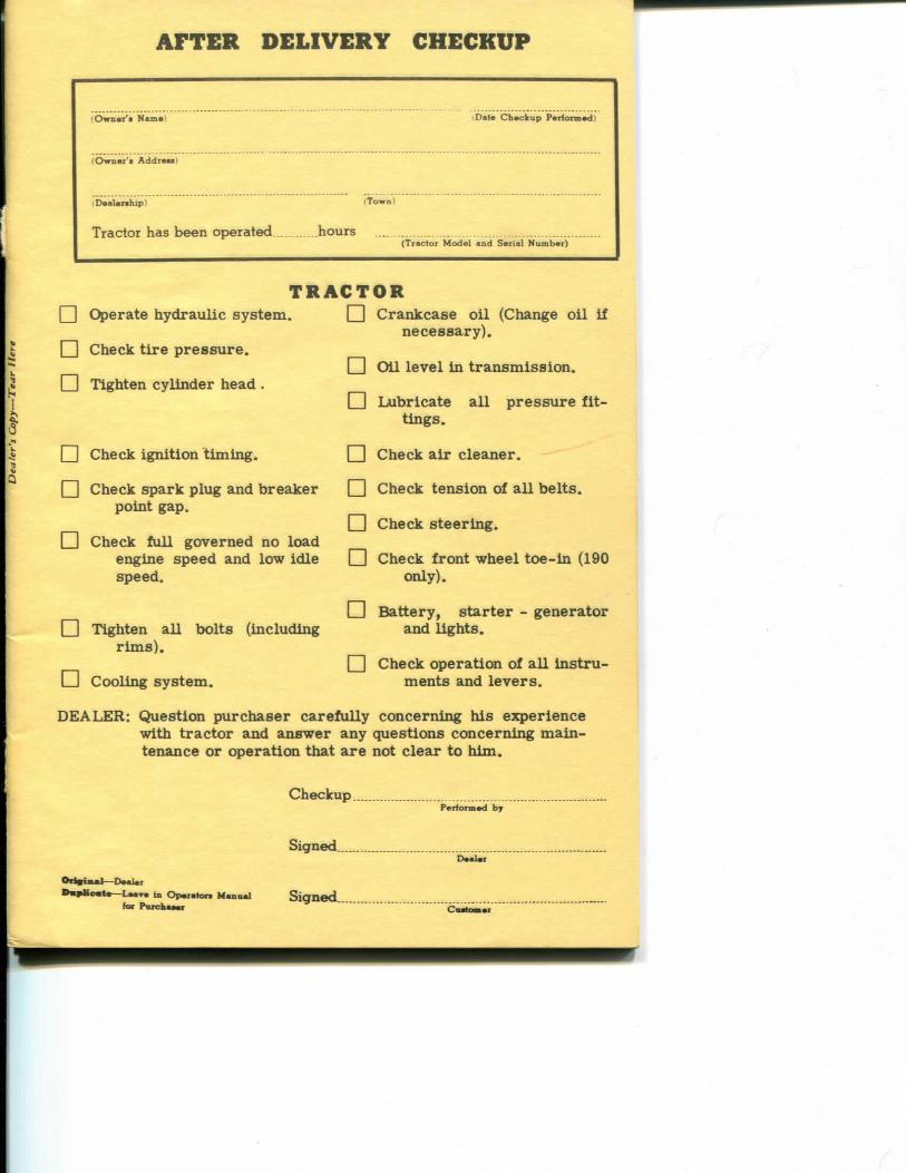
A F T E R D E L I V E R Y CHECKUP
lOwnai' i Nam*)
'Qwnai' i A d d r e u )
(Date Chackup Parforaiad)
(Daa i a^ip) (Town)
Tractor has been operated hours (Tractoi Model and Seiial Numbat)
I I Operate hydraulic system.
^ Check t i r e pressure.
Tighten cylinder head.
T R A C T O R Crankcase o i l (Change o i l i f
necessary).
r~l O i l level i n t ransmission.
^ Check ignit ion t iming .
Check spark plug and breaker point gap.
Check fu l l governed no load engine speed and low idle speed.
Tighten a l l bolts (including r i m s ) .
Lubricate a l l pressure f i t t ings.
Check a i r cleaner.
Check tension of a l l belts.
Check steering.
I ] Check front wheel toe- in (190 only).
Battery, s tar ter - generator and l ights .
• Cooling system. ^ Check operation of aU in s t ru
ments and levers .
DEALER: Question purchaser carefully concerning his experience wi th t ractor and answer any questions concerning maintenance or operation that are not clear to h i m .
Checkup.
Signed
Parformad hy
Daalai
O r t g i M l — D m W t D a ^ M t o — L a a r a in Op»r«taw MantMJ
ftn Purchaaai Signed.
Coalomar

T O T H E P U R C H A S E R O F A C A S E T R A C T O R The care you give your new Case Tractor w i l l greatly determine
the satisfaction and service l ife you w i l l obtain f rom i t . Use this manual as your guide. By observing the instructions and suggestions in this manual, your Case Tractor w i l l serve you w e l l for many years.
As an Authorized Case Dealer, we stock Genuine Case Parts , which are manufactured wi th the same precision and s k i l l as the or iginal equipment. Our factory trained staff is kept w e l l informed on the best methods of servicing Case equipment and is ready and able to help you.
Should you require additional aid or informat ion, contact us.
To insure efficient and prompt service, please furnish us wi th the Model, Serial , Engine Model Number and Engine Specification Number of your Tractor in a l l correspondence or contacts.
H I F O L K S M ' m S a m m y S a f e t y ,
L o o k f o r m e t o p o i n t o u t
i m p o r t a n t S o f e t y P r e c a u t i o n s
1

S E R I A L N U M B E R When ordermg parts f rom your Authorizled Case Dealer and in
a l l contacts or correspondence wi th your dealer relat ive to the Tractor always specify the Ser ia l , Model and Engine Numbers of your Tractor .
The Model and Serial Numbers are stamped on the number plate located on the instrument panel. Figure 3. The Engine, Model , Serial and Engine Specification Numbers are stamped on aplate fastened to the r ight hand side of the engine, Figure 4.
Figure 3 Figure 4
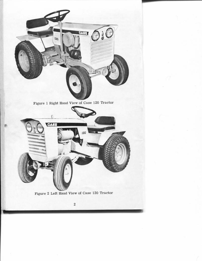
The te rms "Right Hand" and "Left Hand" whenever used i n this manual apply to the tractor when facing i n the direct ion the tractor w i l l move i n forward operation.
For reference, f i l l in the Serial Number, Model Number and Engine Numbers of your Tractor i n the spaces provided below.
Tractor Model Number
Tractor Serial Number
Engine Model Number ;
Engine Serial Number .
Engine Specification Number
3

S P E C I F I C A T I O N S G e n e r a l
T y p e . __ Kohler Model___ _ _ _ K241A Cycle _ 4 Cylinders 1 Cylinder Bore 3-1/4 i n . Stroke _ _ 2-7/8 i n . Piston Displacement 23.9 cu. i n . Horsepower 10 HP Compression Ratio 6 to 1 Ful l Load Speed 3500 RPM No Load Speed 3600 RPM Idle Speed 1000 RPM Valve Clearance Cold (Intake) .010 i n . Valve Clearance Cold (Exhaust) _020 i n .
P i s t o n a n d C o n n e c t i n g R o d
Piston Aluminum Compression Rings 2 Oi l Rings 1 Connecting Rod , Aluminum
F u e l S y s t e m Carburetor Fi l ter Screen Fuel Tank Capacity
I g n i t i o n S y s t e m
Breaker Point Gap .020 i n . Ignition Timing SP M a r k
Spark Plug Prestoli te 14 L7 or equivalent Thread __ 14 M M Gap „ _ - 025"
1" SAE Flange In Sediment Bowl
5 Quarts
4

C o o l i n g S y s t e m Blower Forced air wi th baffles direct ing a i r
around finned cylinder and head area
E l e c t r i c a l S y s t e m
Type of System 12 Vol t , Negative Ground Battery Autoli te LU7 Starter-Generator 12 Vol t Voltage Regulator Automatic Type Head Lights - 1 2 Vol t
C o m b i n a t i o n B r a k e a n d T r a c t o r C l u t c h Type Brake Mechanical, operated by pedal on right side of
t rac tor . Type Clutch Mechanical disc, operates in conjunction with
brake pedal. T r a n s m i s s i o n Type Hydra-Static Mechanical Range High and Low
SPEED RANGE
FIRST .75 MPH SECOND 2.2 MPH THIRD 4.0 MPH FOURTH 7.4 MPH REVERSE 2.6 MPH
WHEELS AND TIRES
Tire Size PLY Type PSI
FRONT Recommended Max.
6.50-8 2 Terra 8 14 4.80-8 2 Rib 16 22
REAR
8.50-12 2 Turf 8 10 8.00-16 2 Lug or Tur f 8 14
5
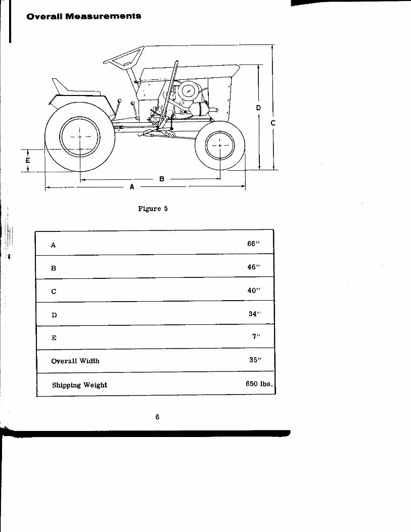
O v e r a l l M e a s u r e m e n t s
B A
Figure 5
A 66"
B 46"
C 40"
D 34"
E 7"
Overall Width 35"
Shipping Weight 650 lbs.
6
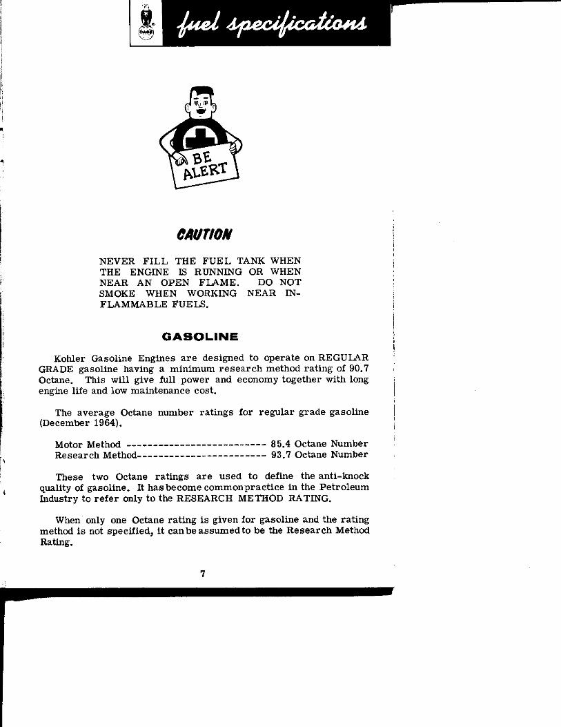
CMTION
NEVER F I L L THE F U E L TANK WHEN THE ENGINE IS RUNNING OR WHEN NEAR A N OPEN F L A M E . DO NOT SMOKE WHEN WORKING NEAR I N F L A M M A B L E FUELS.
G A S O U N E Kohler Gasoline Engines are designed to operate on REGULAR
GRADE gasoline having a min imum research method rat ing of 90.7 Octane. This w i l l give fu l l power and economy together wi th long engine life and low maintenance cost.
The average Octane number ratings for regular grade gasoline (December 1964).
Motor Method 85.4 Octane Number Research Method 93.7 Octane Number
These two Octane ratings are used to define the anti-knock quality of gasoline. I t has become commonpractice i n the Petroleum Industry to refer only to the RESEARCH METHOD RATING.
When only one Octane ra t ing is given for gasoline and the ra t ing method is not specified, i t can be assumed to be the Research Method Rathig,
7

F U E L C O N D I T I O N E R
The following "Fuel Conditioner" recommendations are made for areas troubled wi th gum and varnish i n the fuel:
1, Obtain a "Case Conditioner" and use i t as fol lows:
A . Add i t to the fuel i n the main storage tank.
B. Add a smal l quantity to the Tractor fuel tank daily.
C. Use the "Conditioner" per iodical ly , or when any symptoms develop in the engine that indicate gum and varnish deposits in the Fuel System.
MOU
Refer to the instructions furnished wi th the "Conditioner" as to the amount that should be used.
Figure 6
IMPORTANT 1. Buy Fuel in quantities that w i l l be used up in 90 days or less.
2. Protect main storage tank wi th a shelter so the fuel can be kept as cool as possible.
8

S A F E T Y P R E C A U T I O N S
1. Before start ing the engine, be sure a l l operating controls are i n NEUTRAL and the t rac tor is on a f la t , level surface.
2. Never operate any of the controls f rom any position but seated in the operator's seat.
3. Be extra careful when going down steep grades. 4. Drive at a speed slow enough to insure safety and complete con
t r o l , especially over rough t e r r a in . 5. Reduce ground speed when making a tu rn , going down h i l l or ap
plying the brake. 6. Always operate the t rac tor i n f i r s t or second gear whenever on
hi l ls or steep inclines. 7. Never park the t ractor on a h i l l or incline and leave unattended. 8. Be certain the clutch and brake linkage is maintained in proper
adjustment. See Preventive Maintenance Section. 9. Never leave the engine running while i t i s imattended.
10. Never dismount f rom a Tractor when i t i s i n motion. 11. Never pe rmi t persons other than the operator to r ide on the
Tractor . 12. Never stand between a Tractor and machine when hitching unless
the shift lever is i n neutral . 13. Do not o i l , grease or adjust a Tractor when the engine is running. 14. Never refuel a Tractor when the engine is hot or running. 15. Do not smoke when refueling, 16. Never operate a Tractor i n a closed shed or garage. 17. Do not wear loose f i t t ing clothing which may catch in the moving
parts. 18. To prevent highway accidents, use red warning flags in the day
time and red warning lamps at night, 19. Always have PTO lever disengaged and the brake pedal depressed
and locked when parking or s tart ing the Tractor . 20. REMEMBER, A CAREFUL OPERATOR IS ALWAYS THE BEST
INSURANCE AGAINST AN ACCIDENT.
9

10

S E R V I C E P O I N T S
1 F r o n t Sp ind les 2 / — X HOURS ( 5 ) OR
^ D A I L Y
2 F r o n t W h e e l B e a r i n g s o r B u s h i n g s 2 / — X HOURS ( 5 ) OR
^ D A I L Y 3 Eng ine O i l * 1
/ — X HOURS ( 5 ) OR
^ D A I L Y 4 B l o w e r A i r I n t a k e S c r e e n 1
/ — X HOURS ( 5 ) OR
^ D A I L Y
5 Eng ine O i l 2
HOURS ® OR
W E E K L Y
6 A i r L e a k s •*
HOURS ® OR
W E E K L Y
7 T i e R o d and D r a g L i n k 4 HOURS
® OR W E E K L Y
8 I m p l e m e n t L e v e r a n d Re lease 3 HOURS ® OR
W E E K L Y 9 B a t t e r y 1
HOURS ® OR
W E E K L Y 10 A i r C l e a n e r *•• 1
HOURS ® OR
W E E K L Y
U B r a k e L i n k a g e and L o c k 3
HOURS ® OR
W E E K L Y
12 F r o n t A x l e P i v o t 1
HOURS ® OR
W E E K L Y
13 S t e e r i n g Gear B o x °° 1
A HOURS
/ 'UO \V
14 S p a r k P l u g ° 1 A HOURS
/ 'UO \V 15 C r a n k c a s e B r e a t h e r ••* 1
A HOURS
/ 'UO \V 16 B r e a k e r P o i n t s ° 1
A HOURS
/ 'UO \V 16 B r e a k e r P o i n t s ° 1
17 Choke and T h r o t t l e Cab les 2
18 T r a n s m i s s i o n L u b r i c a n t + 1 18 T r a n s m i s s i o n L u b r i c a n t + 1 M H M H H H U U K b
miiiH OR 19 A i r C l e a n e r E l e m e n t **• 1 M H M H H H U U K b
miiiH OR 20 Eng ine C o o l i n g F i n s *•* 1 • • • • Y E A R L Y
*Keep o i l level between marks on gauge (Capacity 3 pts.) **Be sure there are no leaks between gaskets, joints at carburetor,
air cleaner and cylinder block ***More often i n dusty conditions.
"Clean and regap, °°One stroke - Do not overiubricate +Maintain level at check plug on rear side. When changing, r e f i l l
with 3 pints of Shell Macoma #72 lubricant or the equivalent, such as SAE90 or SAE80 Use number 1 gun grease (Li th ium Base) for a l l pressure f i t t ings. (As many strokes as required.)
11

E N G I N E L U B R I C A T I O N
S e l e c t i o n o f L u b r i c a t i n g O i l I t i s extremely important that you select and use in your Case
Tractor a stable, high quality, "SAE - MS or DM Service Class i f i cation O i l that has passed Automotive Manufacturers Association (AMA) Test Sequences I , I I , and I I I .
E n g i n e O i l S A E V i s c o s i t y R a t i n g
SAE 30 A i r Temperatures-SO" F and Above
SAE 10-W A i r Temperatures 0" F to 30' F
SAE 5-W or 5W-20 A i r Temperatures 0* F or Below
R E G U L A R O I L C H A N G E
Dra in and r e f i l l the crankcase at least every 25 hours of operat ion.
If the engine service is severe - (frequent stopping and s tar t ing, high or low operating temperature) - the crankcase should be drained more often to prevent the format ion of sludge or harmful deposits in the engine.
C R A N K C A S E O I L C H A N G E
IMPORTANT 1. When just the crankcase is drained, always r e f i l l w i t h 3 measured
pints of o i l . Do not r e f i l l using the dipstick as a guide.
2. Operate the engine for a few minutes; then check the o i l l eve l wi th the dipstick.
Be sure to allow sufficient t ime for the o i l to run down off the engine parts .
3. By following the above procedure, you w i l l prevent over f i l l ing or underf i l l ing the crankcase, either of which can be detr imental to the engine service l ife and w i l l give you false o i l consumption records.
12
R U N - I N P R O C E D U R E
Your new t ractor should be subjected to a r u n - i n per iod before i t is operated at f u l l load. Dr ive the t rac tor for several hours to get the feel of operation. Actuate the speed control lever through Its fuU range dtu-ing the r u n - i n per iod .
P R E - S T A R T I N G C H E C K L I S T Before start ing your new Case Trac tor for the f i r s t t ime and be
fore each operating per iod thereafter, chedc the fol lowing.
1. MAKE SURE EVERYONE RESPONSIBLE FOR THE TRACTOR'S OPERATION AND MAINTENANCE UNDERSTANDS THE IMPORTANCE OF CLEAN F U E L .
2. Check that a l l lubricat ing fi t t ings are serviced as directed i n the Lubrication Chart.
3. Check that the crankcase and t ransmission housing is f i l l e d to levels indicated in the Lubricat ion Chart.
4. Be sure a i r cleaner and blower a i r intake screen on engine are free of obstructions and excessive d i r t .
5. Check tliat t rac tor fuel tank is f i l l e d wi th clean fuel that meets requirements l is ted under Fuel Specifications. Always wipe fuel tank cap clean before removing i t . Be sure vent hole i n fuel tank is open.
13

O P E R A T I N G C O N T R O L S A N D I N S T R U M E N T S
D I S C N G A O E T H A T
Figure 7
1. STARTER KEY - Turn the key to the r ight to s tar t the engine. When turning off the engine, t u rn the key to the left and the key w i l l be i n an upright position. Do not tu rn the key a l l the way to the left as this is the accessory posit ion
DO NOT START THE ENGINE WITH THE PTO ENGAGED.
2. CHOKE - To s tar t a cold engine, push choke lever down. Push lever up when engine is warmed up.
3. THROTTLE - When the thrott le lever is a l l the way up, the engine should be id l ing . To increase the engine RPM, push the lever downward u n t i l the desired throt t le s e t t i i ^ is obtained.
14

4. RANGE AND DIRECTION SELECTOR LEVER - Wi th the selector lever i n neutral , depress the combination clutch and brake pedal and place the lever i n any one of the four forward or one reverse speed ranges to obtain the desired working speed or d i rec t ion .
CAUTION Be sure the selector lever is i n neutral when parking and start ing the t rac tor .
5. COMBINATION CLUTCH AND BRAKE PEDAL - The combination clutch and brake pedal w i l l disengage the t rac t ion clutch on the engine when the pedal is depressed to approximately three-fourths of i ts fu l l t r ave l , thereby stopping the t ransmission drive belt. Depress the pedal ful ly to apply the brake,
6. BRAKING AND PARKING - When making a normal stop, depress the brake pedal about three-fourths of i ts fu l l t r ave l which w i l l stop the transmission drive belt. I f a fast stop is necessary, ful ly depress the pedal to engage the brake band wi th the brake drum on the transmission.
NOT£ Always engage and lock the brake when parking the t rac tor . The brake is locked by tightening the lock lever (6, Figure
wi th the brake pedal fully depressed.
Make certain the brake band is maintained in proper adjustment. Should the brake band become worn or loosened, the t rac t ion clutch on the engine can be r e engaged when excessive pressure i s applied to the brake pedal. Refer to the Brake, Clutch and Drive Bel t Adjustment instructions i n the Preventive M a i n tenance Section.
7. UGHT SWITCH - Pu l l the Ught switch out to t u rn on the headlights and push in to tu rn off the headlights.
8. AMMETER WARNING LIGHT - The warning l ight goes on when the key switch is turned on and should go off when the engine starts. I f the ammeter warning l ight does not go off when the engine starts and is running, i t i s an indication that the battery is discharging and the generator is not supplying current . STOP THE ENGINE AND CHECK FOR THE CAUSE.
If the ammeter l ight f l i ckers when the engine is at low idle , the battery, generator or regulator may not necessarily require servicing. However, i f the warning light remains on when engine speed is increased, stop the engine immediately and check for the cause.
15

O P E R A T I N G C O N T R O L S ( C o n t i n u e d )
9. IMPLEMENT L I F T LEVER - The implement lever is used to raise or lower the implement and also to hold the implement at any given level . The wing nut at the base can be turned in or out to adjust the min imum operating height of an attachment. When transporting the attachment, pu l l the l i f t lever back unt i l the catch engages. Depress the button at the top of the lever to r e lease and lower the attachment to desired operating height. A slight pull ing pressure on the lever w i l l pe rmi t the release button to be more easily depressed.
PTO LEVER - To engage the attachment dr ive clutch, move the PTO lever to the r igh t . To disengage, move the lever back to the left. Be sure the PTO lever is in the off position when parking or start ing the Trac tor .
Figure 7a
16

S T A R T I N G P R O C E D U R E
R A N G E S E L E C T O R L E V E R
S T A R T E R K E Y
P T O L E V E R
T H R O T T L E
C H O K E
Figure 8
1. Place the range selector lever i n the NEUTRAL position.
2. Place the PTO lever i n NEUTRAL position.
3. Depress the clutch and brake pedal.
4. Close the choke by pushing the control lever down. More or less choking may be necessary due to variations in temperature, grade of fuel, etc. L i t t l e or no choking w i l l be needed when engine is warm. In cold weather, i t is advisable to position the thrott le lever about one-third open.
5. Turn the starter key to the r ight to s tar t engine; then release key.
6. After the engine starts and runs, push the choke control lever a l l the way up. Always allow engine to warm up before applying a load. Release the brake pedal slowly after engine starts . If range selector lever is i n proper NEUTRAL posit ion, t rac tor w i l l not move.
CAUTION DO NOT USE THE STARTER-GENERATOR LONGER THAN 30 SECONDS WITHOUT I N TERRUPTION. WAIT A T LEAST 3 MINUTES SO THE STARTER-GENERATOR CAN COOL OR SERIOUS DAMAGE COULD RESULT.
S T O P P I N G T H E E N G I N E 1. An engine that has been working under load should idle for a few
minutes so the engine parts can cool evenly before i t i s shut off.
2. Turn starter key to "OFF" or upright position.
17

PREVENTIVE MAINTENANCE IS IMPORTANT TO YOU!
AS THE OWNER OF CASE TRACTOR, YOU POSSESS A M A CHINE THAT IS MADE TO THE HIGHEST STANDARDS POSSIBLE.
PREVENTIVE MAINTENANCE BY YOU OR YOUR OPERATOR IS THE EASIEST AND MOST ECONOMICAL MEANS OF ASSURING MANY SATISFACTORY PRODUCTIVE HOURS OF OPERATION.
The preceding sections of t l i i s operator 's manual have dealt wi th instructions necessary for daily operation of your Trac tor . The f o l lowing subjects present detailed instructions concerning the care and adjustment of the Trac tor .
18

S T A R T E R - G E N E R A T O R B E L T A D J U S T M E N T
The starter - generator drive belt should be checked l o r excessive looseness and wear after the f i r s t 10 hours of operation and each 25 hours of operation thereafter. The belt tension is correct when the belt can be depressed 1/4" (fingerpressure)midway between the pulleys, Figure 10.
IMPORTANT
Under no circumstances should a pry bar be used on the starter-generator to obtain belt tension, as damage to the bearings could resul t .
S T A R T E R - G E N E R A T O R P U L L E Y
C R A N K S H A F T PULLEY
Figure 9
S T A R T E R - G E N E R A T O R B E L T R E P L A C E M E N T
Loosen the adjusting bracket bolt and the two mounting bolts , swing the starter-generator toward engine and remove belt , Figure 11.
Instal l new belt and using hand pressure, pu l l the s tar t er-generator outward un t i l proper belt adjustment is obtained, Figure 10. Tighten the two mounting bolts and adjusting bracket bolt .
Figure 10

B R A K E A N D C L U T C H P E D A L A D J U S T M E N T
IMPORTANT Check the clutch and brake pedal for proper adjustment every month or 100 hours of operation. Adjustment is necessary when normal pressure on the pedal w i l l not sufficiently engage the brake band wi th the brake drum and stop the t rac tor .
1. Loosen lock lever " A " unt i l brake pedal operates smoothly.
2, Loosen double nuts " B " on brake band l ink rod un t i l combination clutch and brake pedal "C" depresses ful ly under "hand" pressure.
When brake is out of adjustment, excessive pressure on the pedal can cause the t ract ion clutch to r e engage.
3. Fully depress clutch and brake pedal. Note and mark this posi tion of pedal. Then loosen lock nut " B " and tighten adjusting nut " B " un t i l foot pedal is raised 1" f rom previously marked fully depressed position.
4, Start t ractor and check clutch and brake for proper operation. The clutch should disengage just before the brake engages. Nut " B " can be tightened or loosened sl ightly un t i l proper adjustment is obtained.
5. Holding the inside adjusting nut " B " in i ts proper posit ion, tighten the outer nut securely.
20

T R A N S M I S S I O N D R I V E B E L T A D J U S T M E N T
Figure 12
NOTE Check the transmission dr ive belt for proper adjustment monthly or every 100 hours of operation. The belt is under proper tension i f normal finger pressure (about ten pounds) deflects the belt approximately 1/4" midway between the pulleys. (See Figure 12a.) The tension can be checked by depressing the lower belt section without removing the guard. If readjustment or replacement is necessary, proceed as follows:
1. Loosen the two nuts " B " and one nut " D " on the brake band and loosen lock lever " A " .
2. Loosen the four bolts " E " and one bolt " F " .
3. To tighten the drive belt, turn the two bolts "G" clockwise. One bolt " G " is located on each side of the t rac tor . To loosen the drive belt, tu rn these bolts counterclockwise. I t is important that these two (2) bolts be adjusted equally.
If replacing the dr ive belt, loosen two bolts "G" sufficiently to i n s ta l l the new belt without stretching or "roping" i t over the pulleys.
21

eAUTIOH If replacing the drive belt, loosen two bolts "G" sufficiently to ins ta l l the new belt without stretching or "roping" i t over the pulleys.
4. When drive belt is under proper tension, retighten the five (5) bolts " E " and " F " , and tighten nut " D " wi th the front of the brake band in light contact wi th the brake wheel.
5. Readjust nuts " B " and " D " as outlined in "Brake and Clutch A d justment." See Page 20.
A I R C L E A N E R
Remove and clean element after each 25 hours or weekly. I n stal l new element every 1000 hours or yearly or when loss of power is noticeable.
To clean the element, remove the wing nut. washer, cleaner cover and remove the element. Tap element l ight ly on a flat surface to cause the loose d i r t to fa l l off. Handle the paper element wi th care to avoid damage to element.
CAUTION
Do not wash, use compressed air or solvent to clean element.
W I N G NUT
Replace the element wi th a new one i f d i r t does not drop off easily or i f i t is bent, crushed, or damaged. When replacing the element, be sure i t f i ts snugly around the inside edge of the a i r cleaner base. Then replace the cover, washer and tighten the wing nut finger t ight .
22

C A R B U R E T O R The carburetor has three simple adjustments:
1. High Speed Adjustment 2. Idle Mixture Adjustment 3. Idle Speed Adjustment
H i g h S p e e d A d j u s t m e n t
Adjust the high speed screw, Figure 13, by turning the adjusting screw clockwise (in) i m t i l the engine misf i res or falls off; then tu rn the adjusting screw counterclockwise (out) i m t i l the engine runs smoothly, approximately two turns.
Place the t rac tor under load and observe how the engine handles the load. Loss of power or tendency to s ta l l indicates a lean m i x ture. Turn adjusting screw counterclockwise not more than 1/8 of a turn and again t r y the engine performance. When the high speed screw is correct ly adjusted, i t w i l l not be necessary to reset the carburetor unless load conditions or fuel quality have been radical ly changed.
Operating an engine on too lean a mixture causes loss of power and high exhaust heat.
Figure 13
I d i i n g S p e e d a n d i d i i n g IV I ix tu re A d j u s t m e n t Turn the idle mixture screw. Figure 13, counterclockwise ap
proximately 1-1/4 turns f rom the closed posit ion. Place the throt t le in 1/2 open position and start engine. With the throt t le a l l the way up, turn the idle speed adjusting screw. Figure 13, un t i l 1000 RPM is obtained. The idle mixture screw can be adjusted i n or out unt i l the engine runs smoothly while maintaining 1000 RPM with the.idle speed adjusting screw.
23

s p a r k P l u g The type spark plug provided in your engine is l i s ted as medium
in the spark plug heat range chart - Prestoli te 14 L7 or equivalent. Shank Length 7/16" Thread Size 14 M M Gap Setting .025 Inch
NOU It is possible that under unusual conditions, "colder "type spark plug may be required^ Consult your Authorized Case Dealer regarding the proper type spark plug to use for your par t icular condition.
The spark plug plays a very important part in the power fuel economy and general performance of your engine. The outside of plug should be cleaned frequently to prevent shorting of the plug.
The spark plug should be removed, checked, cleaned and gapped at the end of every 100 hours of operation.
R e m o v i n g
I t is important to select the exact size spark plug wrench. The wrong size or type wrench may cause dis tor t ion and insulator breakage. Always use a spark plug wrench or a thin w a l l deep socket wrench of the recommended size.
Thoroughly clean the spark plug, including the threads. Check the electrode gaps using a .025 inch gauge. A very slight drag should be fel t when the gauge wi re passes between the electrodes.
Reset the gaps by bending the side electrode only. Never touch the center electrode.
I n s t a l l i n g
Instal l the spark plug, wi th a new gasket, i n the engine and seat the plug on the gasket, finger tight. Tighten the plug about 3/4 of a turn after the plug is seated f i r m l y on i t s gasket. If a torque wrench is available, tighten the plug to 27 foot-pounds. This w i l l assure proper seating and sealing of the spark plug.
T H I S TYPE O F C R A C K IS SUALLY C A U S E D BY
1 . D R O P P I N G P L U G
3 . S T R I K I N G P L U G W I T H W R E N C H D U R I N G I N S T A L L A T I O N
R O U N D FEELER G A U G E W I L L G I V E A M O R E A C C U R A T E R E A D I N G
Figure 14
24

I G N I T I O N T I M I N G
A d j u s t i n g B r e a k e r P o i n t s
Every 100 hours of operation, the breaker point cover should be removed and the points cleaned and reset. P i t ted or burned points should be replaced. Regap the points to .020 inch. Loosen the point retaining screw and using a screwdriver in the adjusting slot, increase or decrease the point gap to obtain .020 inch. Figure 15. Retighten the point retaining screw.
im\ R E T A I N I N G S C R E W
A D J U S T I N G S L O T
B R E A K E R P O I N T S
r
T i m i n g Figure 15
The t iming can be checked by removing the plug f rom the t iming hole located on the left hand side of the bearing plate.
When the t iming is checked with a t iming light, the SP mark must be centered in the t iming hole. Figure 16. H not, adjust the breaker points as described above.
O Figure 16
25

E L E C T R I C A L S Y S T E M
H e a d l i g h t s
A l l genuine Case 12 Vol t Replacement Sealed Units have a label marked "12-V" or are stamped "12-V" on the back of the unit . This marking is placed on the unit to make sure you do not ins ta l l a 6 volt sealed unit which would burn out immediately.
To ins ta l l a new headlight, remove the retainer screws and r e tainer, Figure 17. Pul l out the old unit and disconnect the wires as shown in Figure 17. Instal l the new gasket furnished wi th your r e placement Case headlight.
Figure 17 When install ing the new sealed unit , make sure the connections
are tight.
•VtS, MR PEAtER. I V E S t u p i e p t h e MAMUAL"
26
S T O R A G E B A T T E R Y
When working around a storage battery, remember a i l of i t s exposed metal parts are " l i ve" . Never lay a metal object across the terminals as spark or short c i rcu i t may resul t . Sparks, lighted matches and exposed flames must be kept away f rom the battery due to the presence of explosive gas in the battery.
The l iquid i n the battery is acid. Use care not to s p i l l i t on hands or clothing.
R u l e s f o r B a t t e r y C a r e
1. Add pure or d is t i l led water, as needed, to keep the separators covered. Check every 25 hours or weekly depending on a i r temperature. Normal water consumption would be approximately 1 ounce every 25 hours of operation. If i t i s greater, either the case is leaking or the regulator i s overcharging and must be adjusted.
2. Keep the battery i n a healthy state of charge as shown by hydrometer readings.
3. Make sure the bat tery is securely fastened in posit ion. Cable leading f rom the battery should not touch ce l l connectors or lay on the battery container.
4. Keep the battery clean and d ry .
If a battery w i l l not hold a charge, replace i t wi th a new one meeting the specifications as l is ted i n the specification section.
Each week, and before adding water , take a hydrometer reading from every ce l l . The gravity reading f rom each ce l l should show f u l l charge.
MOTi
The f u l l charge gravi ty reading w i l l usually be indicated on the battery. A battery having a reading of 1.175 w i l l freeze at approximately 0* Fahrenheit temperature.
27

A d d i n g W a t e r
Unless the tap water in your area is "approved" (water free of scale-forming minerals), always add distilled water to the battery.
When water is added during freezing weather, the battery must receive a charge immediately to mix the water and electrolyte. If it is not mixed, the water will remain at the top and freeze.
Always keep the vent plugs in place and tight. Be sure the vent holes are free of dirt to prevent gas pressure in cells from breaking the sealing or the container.
C a b l e T e r m i n a l s a n d B a t t e r y P o s t s
The battery terminals must be kept clean and tight. A good method of cleaning terminals is to remove all excess corrosion with a wire brush, then wash with a weak baking soda solution or ammonia. After cleaning, a thin coating of vaseline or light cup grease will retard further corrosion.
When the Tractor is not in active use, the battery will require a charge at sufficient intervals to keep the hydrometer reading at or above 1.250. An idle storage battery will slowly discharge.
Check the liquid level in each cell weekly by removing the vent plugs. Water must be added before the tops of the separators are exposed. DO NOT OVERFILL.
V e n t P l u g s
I d l e B a t t e r y
28

t o CD
K E Y S W I T C H
G E N E R A T O R L I G H T
L I G H T S W I T C H
V O L T A G E R E G U L A T O R
W I R E C O L O R C O D E 1 R E D 2 Y E L L O W 3 W H I T E 4 B L A C K 5 G R E E N 6 B L U E
S T A R T E R G E N E R A T O R
H E A D L I G H T S
C O N D E N S E R
I G N I T I O N C O I L
z o
0 > 0
>

T A B L E O F C O N T E N T S
SERIAL NUMBER 3
ENGINE SPECIFICATIONS 4
GENERAL SPECIFICATIONS 5 Cooling System 5 Elec t r ica l System 5 Brake 5 Transmission 5 Wheels and Ti res 5 Overal l Measurements 6
FUEL SPECIFICATIONS 7 Fuel Conditioner 8
SAFETY PRECAUTIONS 9
LUBRICATION 10 Lubrication Chart 10-11 Engine Lubrication 12
OPERATING INSTRUCTIONS 13 Run-in Procedure 13 Pre-Starting Check U s t 13 Operating Controls and Instruments 14 th ru 16 Starting Procedure 17
PREVENTIVE MAINTENANCE 18 Starter-Generator Belt Adjustment .» 19 Starter-Generator Belt Replacement 19 Brake and Clutch Pedal Adjustment 20 Transmission Dr ive Belt Adjustment 21 A i r Cleaner 22 Carburetor Adjustments 23 Spark Plug 24 Ignition Timing 25 Adjusting Breaker Points 25 Elec t r ica l System 26 Storage Battery 27-28 Wir ing Diagram 29
ATTACHMENTS . . . . . . . . . . . . . . . . . . . . . . . . . . ^ . - 31-32

A V A I L A B L E A T T A C H M E N T S
1 0 0 0 P O U N D C A P A C I T Y D U M P C A R T
D R A W B A R E X T E N S I O N
T H R E E S P I N D L E R O T A R Y M O W E R
f
M A N Y O T H E R U S E F U L A T T A C H M E N T S A R E A V A I L A B L E T H R O U G H Y O U R J . I . C A S E D E A L E R .
31

A V A I L A B L E A T T A C H M E N T S
D I S C H A R R O W
R O L L E R
S P R I N G H A R R O W S E E D E R
M A N Y O T H E R U S E F U L A T T A C H M E N T S A R E A V A I L A B L E T H R O U G H Y O U R J . I . C A S E D E A L E R .
32

L U B R I C A T I O N A N D P R E V E N T I V E M A I N T E N A N C E R E C O R D S
DESCRIPTION HOURS
IS i n y o u r h a n d s
be c a r e f u l a v o i d a c c i d e n t s
As a member of the National Safety Council, we are pr iv i leged to use the Green Cross for Safety to designate not only our interest in Safety, but to point out more c lear ly the safety precautions in this manual.

(
win. Form 9-1841 P R I C E 25 C E N T S CCNBO
f