Mode-Field Diameter and “Spot Size” Measurements … · Petermann II MFD Issues Errors1,2 •...
29
Mode-Field Diameter and “Spot Size” Measurements of Lensed and Tapered Specialty Fibers Jeffrey L. Guttman Photon Inc. 6860 Santa Teresa Blvd. San Jose, CA 95119 National Institute of Standards and Technology Symposium on Optical Fiber Measurements September 24-26, 2002
Transcript of Mode-Field Diameter and “Spot Size” Measurements … · Petermann II MFD Issues Errors1,2 •...

Mode-Field Diameter and “Spot Size”Measurements of Lensed and Tapered
Specialty Fibers
Jeffrey L. Guttman
Photon Inc.6860 Santa Teresa Blvd.
San Jose, CA 95119
National Institute of Standards and TechnologySymposium on Optical Fiber Measurements
September 24-26, 2002

ABSTRACT
The Mode-Field Diameter (MFD) and “spot size” of an assortmentof lensed and tapered specialty fibers were determined from far-field and near-field measurements. In the far field, measurementswere made using a 3D-scanning goniometric radiometer thatprovides a complete hemispherical profile. Indirect measures of thenear field derived from these data are reported, including thePetermann II MFD, the 1/e2 spot size using the far-field Gaussianapproximation, and a measure obtained from 2D Fourier transforminversion of the far field using phase retrieval techniques. In thenear field, direct profile measurements were made using an IRVidicon camera and magnifying objective lenses, with the spot sizereported as the 1/e2 diameter of the imaged profile.

Characterize Lensed and Tapered Fibers at Focus
•Direct Near Field Techniques & Issues
•Indirect Measures from Far Field & Benefits
Near Field Data
Far Field Data
Analysis and Results
Summary
PRESENTATION OUTLINE

Tapered FiberMain and Scattered Beams
1/e2Fiber
Scattered Beam
Main Beam(High NA)
Fiber Mode
10μm
Focus
Direct Near Field SourceMeasurement Techniques/Issues
Camera/Magnifying Objective• Diffraction Limited for “μm-subμm” Structures• NA, MTF, and λ Dependence of Optics• Positioning at Focus• Dynamic Range
Scanning Pinhole/Knife-Edge• Positioning at Focus
Near Field Scanning Optical Microscopy (NSOM)• Speed of Measurement• Positioning at Focus• Expensive

Indirect Near Field Characterizationfrom Far Field Measurement
Far-Field ScanningEase of Measurement• No Optics Limitations• No Access Constraints• Minimal Positioning Required
Large Dynamic RangeCalculate Near Field Quantitiesfrom Measured Far FieldProvides “sub-µm” Resolution

Characterization of Lensed andTapered Fiber
Direct Near Field• 1/e2 Diameter
Indirect Far Field• Gaussian Approximation: d=4λ/πθ
1/e2 Diameter• Petermann II MFD• 2D Fourier Transform with Phase Retrieval
1/e2 Diameter

Near-Field ProfilesFiber #6
100X
40X
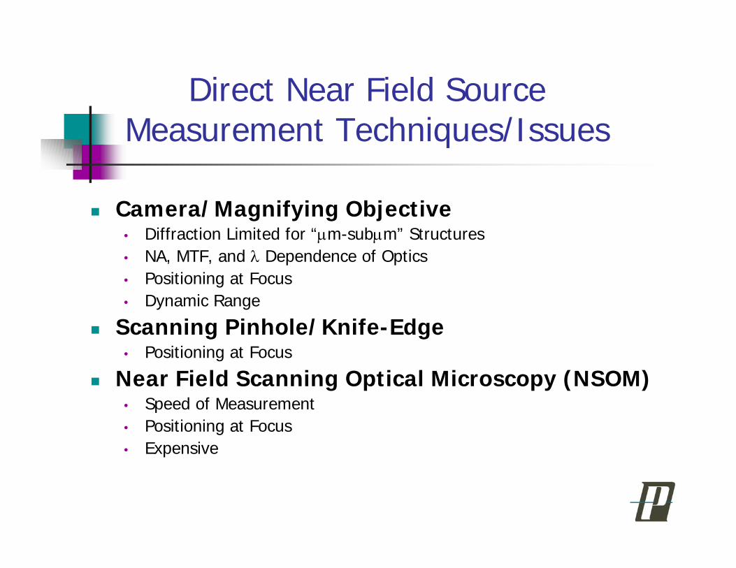
Far-Field Profiles
a.) Fiber #1 b.) Fiber #2
c.) Fiber #3 d.) Fiber #4
e.) Fiber #5 f.) Fiber #6

Petermann II Integral*
MFDFar Field
θθθθ
θθθθ
πλ
dI
dI
cossin)(
cossin)(2MFD
3∫
∫∞
∞−
∞
∞−=
*TIA/EIA FOTP-191

Mode-Field Diametervs
Petermann II Integral Angle
0
1
2
3
4
5
6
7
8
9
10
11
12
0 10 20 30 40 50 60 70 80 90
Petermann II Integral Angle (degrees)
MFD
(mic
rons
)
#1 Major#1 Minor#2 Major#2 Minor#3 Major#3 Minor#4 Major#4 Minor#5 Major#5 Minor#6 Major#6 Minor

Lensed and Tapered FibersMFD vs Integral Angle
Mode-Field Diameter (μm) Fiber 1 2 3 4 5 6 Integral Limit Major and Minor Axes
40 10.406 10.375 5.069 5.118 4.141 4.154 3.851 3.742 3.478 3.506 2.668 1.92045 10.395 10.361 5.054 5.104 4.113 4.128 3.842 3.734 3.442 3.476 2.593 1.90250 10.382 10.345 5.043 5.095 4.100 4.110 3.832 3.725 3.420 3.457 2.391 1.88755 10.367 10.328 5.034 5.087 4.091 4.100 3.823 3.715 3.405 3.443 2.221 1.87360 10.352 10.311 5.026 5.081 4.084 4.094 3.814 3.705 3.395 3.434 2.139 1.851
Average 10.380 10.344 5.045 5.097 4.106 4.117 3.832 3.724 3.428 3.463 2.402 1.887 Difference from Average MFD
40 0.2% 0.3% 0.5% 0.4% 0.9% 0.9% 0.5% 0.5% 1.5% 1.2% 11.1% 1.8%45 0.1% 0.2% 0.2% 0.1% 0.2% 0.3% 0.3% 0.3% 0.4% 0.4% 7.9% 0.8%50 0.0% 0.0% 0.0% 0.0% -0.1% -0.2% 0.0% 0.0% -0.2% -0.2% -0.5% 0.0%55 -0.1% -0.2% -0.2% -0.2% -0.4% -0.4% -0.2% -0.2% -0.7% -0.6% -7.6% -0.7%60 -0.3% -0.3% -0.4% -0.3% -0.5% -0.6% -0.5% -0.5% -1.0% -0.8% -11.0% -1.9%

1/e2 Near Field Diameter from 2DFourier Transform of Far Field
Phase Retrieval Technique:“Error-Reduction” Algorithm*
)](exp[)()](exp[)()(
)]([)](exp[)()(
)](exp[)()(
)]([)](exp[)()(
11
1
xixfxixfx
uxixx
uiuFu
xuiuu
kkk
kkkk
kk
kkkk
g
GFgg
G
gFGG
θθ
θ
φ
φ
′
′′′′
′
==
==
=
==
++
−
*J. R. Fienup, “Phase retrieval algorithms: a comparison,”Applied Optics Vol. 21, No. 15, pp. 2758-2769, Aug. 1982.
•Fourier transform estimate
•Substitute measured modulus
•Inverse Fourier transform
•Apply support constraints

Far Field/Near Field Measurements of1/e2 Spot Size
1/e2 Diameter (μm)Fiber 1 2 3 4 5 6
Method of Analysis Major Axis × Minor Axis1/e2 FF Gaussian 11.77×11.77 6.20×6.16 5.07×5.11 3.64×3.51 4.23×4.25 3.62×2.071/e2 NF Profile 100X 10.29×9.71 4.67×4.67 4.37×4.29 4.23×4.09 3.50×3.36 3.58×2.341/e2 NF Profile 40X 9.24×9.03 4.85×4.73 4.24 ×4.15 3.79×3.55 4.03×3.79 3.55×2.772D FF Fourier Transform 9.94×9.93 5.04×5.03 4.02×4.07 3.60×3.55 3.71×3.30 2.96×1.94
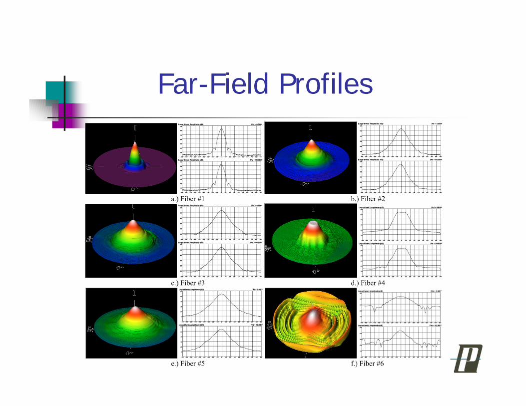
Gaussian Approximation:Is it Appropriate?
G a u s s ia n A p p r o x im a t io n
1
1 0
1 0 0
1 0 0 0
1 0 0 0 0
1 0 0 0 0 0
1 0 0 0 0 0 0
1 0 0 0 0 0 0 0
- 9 0 - 7 0 - 5 0 - 3 0 - 1 0 1 0 3 0 5 0 7 0 9 0
A n g l e ( d e g r e e s )
Am
plit
ud
e (
Arb
itra
ry U
nit
s)
S M F 2 8S M F 2 8 G a u s s ia nL T F # 5L T F # 5 G a u s s ia n

Petermann II MFD Issues
Errors1,2
• Obliquity Factor and Aperture FieldElliptical Fiber3
• Radial Symmetry for Hankel TransformField Within Fiber vs Field at Focus
1 M. Young, “Mode-field Diameter of single-mode optical fiber by far-field scanning”, Applied Optics, Vol. 37, No. 24, August 1998
2 R. C. Wittmann and M. Young, “Are the Formulas for Mode-FieldDiameter Correct?”, NIST SOFM 1998
3 M. Artiglia et al, “Mode Field Diameter Measurements in Single-ModeOptical Fibers”, Journal of Lightwave Technology, Vol. 7, No. 8.August 1989

Is MFD Appropriate for FocusedBeam Diameter in Free Space?
Fraunhofer Diffraction:
2D Fourier Transform Pair1
Similar Expression for Laser BeamPropagation in Free Space2
1 J. W. Goodman, Introduction to Fourier Optics, McGraw-Hill, San Francisco, CA, 1968, p.462 A. E. Siegman, Lasers
∫ ∫∞
∞−
∞
∞−
+
⎥⎦⎤
⎢⎣⎡ +−= ηξηξ
λπηξ
λddyx
zjU
zjeeyxU
yxz
kjjkz
)(2exp),(),()(
222
2)(
max
22 ηξ +>>
kz
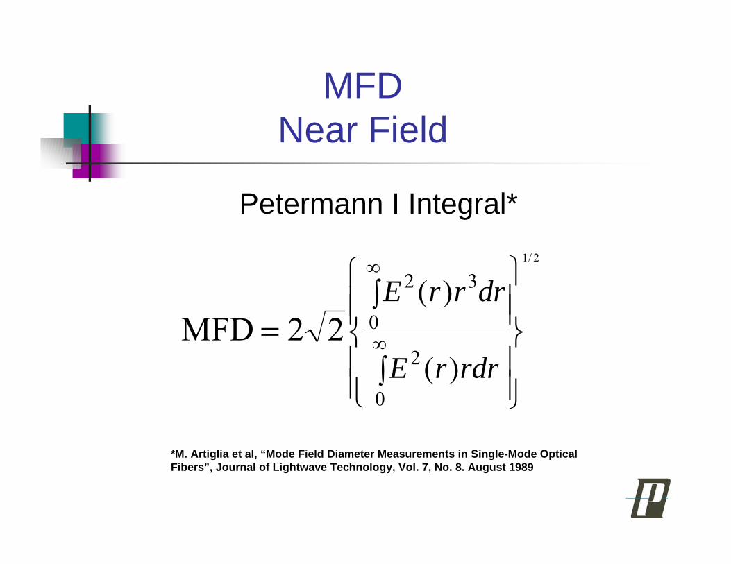
MFDNear Field
Petermann I Integral*
⎪⎪⎭
⎪⎪⎬
⎫
⎪⎪⎩
⎪⎪⎨
⎧
∫
∫∞
∞
=
0
2
0
32
)(
)(2/1
22MFDrdrrE
drrrE
*M. Artiglia et al, “Mode Field Diameter Measurements in Single-Mode OpticalFibers”, Journal of Lightwave Technology, Vol. 7, No. 8. August 1989
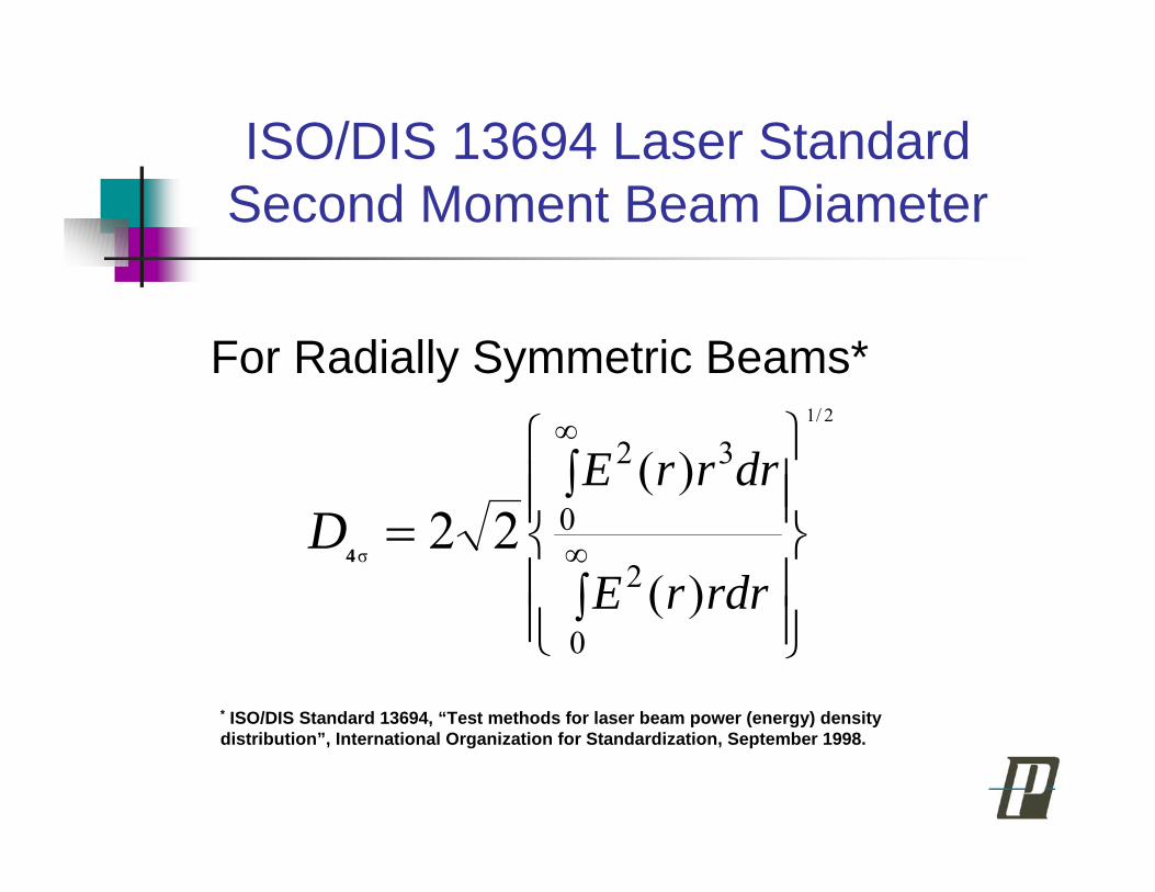
ISO/DIS 13694 Laser StandardSecond Moment Beam Diameter
For Radially Symmetric Beams*
⎪⎪⎭
⎪⎪⎬
⎫
⎪⎪⎩
⎪⎪⎨
⎧
∫
∫∞
∞
=
0
2
0
32
)(
)(2/1
σ22
rdrrE
drrrED
4
* ISO/DIS Standard 13694, “Test methods for laser beam power (energy) densitydistribution”, International Organization for Standardization, September 1998.

Small Spot/High NA Pose Measurement ChallengesFar Field Measurements are Easier to Perform and LessProne to Error than Near Field MeasurementsNear Field Characterization from Far Field:
•Measurement Must Extend to Large Angles….≥ 60°•Gaussian Approximation is Questionable•MFD Appears to be “OK” in Free Space•“θ” is Important and Should Be Specified•2D Fourier Transform Methods Warrant Further Investigation•Different Metrics Yield Different Results
What is the Correct Answer?……...Standardization!
Lensed and Tapered Fiber Characterization
CONCLUSION


Near-Field Profiles

Far-Field Profiles
a.) Fiber #1 b.) Fiber #2
c.) Fiber #3 d.) Fiber #4
e.) Fiber #5 f.) Fiber #6

Far Field Measurement of Mode-FieldDiameter of Optical Fiber
θθθθ
θθθθπλ θ
θ
θ
θ
dI
dIMFD
)cos()(sin)(
)cos()sin()(2)/(
3∫
∫
−
−=
TIA/EIA FOTP-191 Direct Far-Field Method“Reference Method”Petermann II Integral:

θθθθ
θθθθπλ θ
θ
θ
θ
dI
dIMFD
)cos()(sin)(
)cos()sin()(2)/(
3∫
∫
−
−=
Petermann II Integral:
MFDFar Field

MFD
MFD vs. Petermann II Integral Angle
01
23
456
78
910
1112
0 10 20 30 40 50 60 70 80 90
Petermann II Integral Angle (degrees)
MFD
(mic
rons
)
#1 Major#1 Minor#2 Major#2 Minor#3 Major#3 Minor#4 Major#4 Minor#5 Major#5 Minor#6 Major#6 Minor

Far Field/Near Field Measurements of1/e2 Spot Size
1/e2 Diameter (μm)Fiber 1 2 3 4 5 6
Method of Analysis Major Axis × Minor Axis1/e2 FF Gaussian 11.77×11.77 6.20×6.16 5.07×5.11 3.64×3.51 4.23×4.25 3.62×2.071/e2 NF Profile 100X 10.29×9.71 4.67×4.67 4.37×4.29 4.23×4.09 3.50×3.36 3.58×2.341/e2 NF Profile 40X 9.24×9.03 4.85×4.73 4.24 ×4.15 3.79×3.55 4.03×3.79 3.55×2.772D FF Fourier Transform 9.94×9.93 5.04×5.03 4.02×4.07 3.60×3.55 3.71×3.30 2.96×1.94
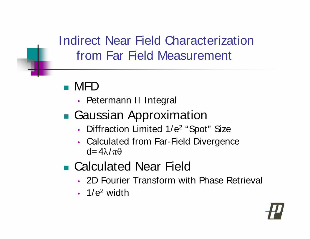
Indirect Near Field Characterizationfrom Far Field Measurement
MFD• Petermann II Integral
Gaussian Approximation• Diffraction Limited 1/e2 “Spot” Size• Calculated from Far-Field Divergence
d=4λ/πθ
Calculated Near Field• 2D Fourier Transform with Phase Retrieval• 1/e2 width

Characterization of Lensed andTapered Fiber
Direct Near FieldIndirect Far FieldIs MFD Appropriate?• Field Within Fiber vs Field at Focus• MFD Errors
Obliquity Factor and Aperture Field1
• Elliptical Fiber
1 Matt Young and Wittman reference


![Computing Extreme Eigenvalues of Large Scale Hankel Tensors · Computing Extreme Eigenvalues of Large Scale Hankel ... automatic control [48], and geophysics ... Computing Extreme](https://static.fdocuments.in/doc/165x107/5b7651297f8b9a8d4c8e780f/computing-extreme-eigenvalues-of-large-scale-hankel-tensors-computing-extreme.jpg)