Mode 20 – High Speed UP/DOWN Counter - … any quadrature encoder, four unique logic states are...
26
1 4 Mode 20 – High Speed UP/DOWN Counter In This Chapter . . . . Ċ Wiring the UP/DOWN Counter Ċ Configuring the UP/DOWN Counter Parameters Ċ Writing the Control Program Ċ Verification of Proper Operation Ċ Troubleshooting
Transcript of Mode 20 – High Speed UP/DOWN Counter - … any quadrature encoder, four unique logic states are...

14Mode 20 –High SpeedUP/DOWN Counter
������������ �������
���� ����������������������
��������� ���������������������� �� ���� �
��� �������������� ���� �� �
���� ������������� �� ��� ����
��� �������������

Mod
e 20
UP
/DO
WN
Cou
nter
Mod
e 20
:U
P/D
OW
N C
ount
er4–2
High Speed UP/DOWN Counter
DL205 High Speed CounterInterface Manual, 2nd Ed, Rev. A
Using the UP/DOWN Counter, Mode 20 (DL240/250–1/260 Only)
It is recommended that you read Chapter 1, Getting Started, which introduces the sixdifferent modes of operation of the D2–CTRINT module, before selecting a mode.Even though several features can be mixed from several modes, you must selectone of the modes as your primary mode. Mode 20, UP/DOWN Counter will be theonly mode discussed in this chapter.It is also important to read Chapter 2, concerning the general guidelines for fieldwiring your device to the module. You may want to refer to Chapter 2 as you learnmore about the D2–CTRINT’s UP/DOWN counting function.
Enable
Input A
C0
Input B
C1
DL240/250–1/260 UP/DOWN Counter Mode 20
connect toground
Programsignals
Reset
Dummy �
D2–CTRINT Terminals
Reset
C0
C2
C1
Reset
Ext. Reset
�
02 01 00
To Terminal
C2
UP Counting
DOWN Counting
Phase A
Phase BEncoder
ProximitySensor
ProximitySensor
Choose from eitherconfiguration
��
���
D2
The above diagram and illustration shows points C0 and C1 which are the twoprimary UP/DOWN counter connecting points for the pulse input devices. Point C2 isthe reset input. The counter can be reset either through the operating program usingrelay ladder logic or they can be reset by an external field device. Points 00 through03 are the respective common connections for the counter inputs and optionalexternal reset. Point 04 and C4 are for pulse output signals and are not used in thismode.

Mode 20
UP
/DO
WN
Counters
Mode 20:
UP
/DO
WN
Counter4–3
High Sped UP/DOWN Counter
DL205 High Speed CounterInterface Manual, 2nd Ed, Rev. A
UP/DOWN Counting Overview
Encoders are used in all types of applications, including machine tooling,semiconductor positioning and multi–axis positioning. In the most general sense,the encoder puts out a certain number of pulses for each revolution of the shaft.Encoders can be easily interfaced to the D2–CTRINT module for accurate positionmonitoring and control. There are two types of encoders available, incremental andabsolute. These encoders have a rotating shaft which are normally coupled(mechanically) to motors for machine control.
The incremental encoder has a pulse output which corresponds to the rotation of theshaft. This pulse output is the encoder resolution corresponding to the number ofpulses per revolution. There are two outputs from an incremental encoder, A and B.There is also an output for home position. The encoder outputs can be used foreither counting or for direction control (quadrature).
The absolute encoder is used for more precise positioning. The output from theabsolute encoder is a binary value relating to degrees per revolution(360/revolution).
Both types of encoders, incremental and absolute, are available fromAutomationDirect. More information about the encoders is available from both ourwebsite and catalog.
There are two basic ways to use the UP/DOWN counter, either for standardUP/DOWN counting from two separate sources (i.e. single pulse from two encoders)or for quadrature UP/DOWN counting using encoder outputs A and B.
The first way, using the D2–CTRINT module as a standard UP/DOWN counter, iscommonly used for position control. For example, a drill head may need to be movedin a certain direction horizontally. At the same time, the drill head position may alsoneed to be tracked. This can be done by counting pulses received from twoencoders. When the drill moves in one direction, an encoder will increment anaccumulated count (UP count). When the drill moves in the opposite direction, asecond encoder will decrement the accumulated count (DOWN count). The drillposition will be known by looking at the accumulated count at any given time.
Using the high speed positioning example, point 00 would receive signals from anencoder that keeps track of movement in one direction, to the right. Point 01 wouldkeep track of movement to the left via a second encoder. Incrementing anddecrementing the UP/DOWN counter can happen simultaneously or duringseparate intervals of time.
00
01
Reset02
UP Count
DOWN Count
Encoder
Encoder
Drill Positioning Example
Drill Moving to Right
Drill Moving to Left
EncodersIn General
StandardUP/DOWNCounting

Mod
e 20
UP
/DO
WN
Cou
nter
Mod
e 20
:U
P/D
OW
N C
ount
er4–4
High Speed UP/DOWN Counter
DL205 High Speed CounterInterface Manual, 2nd Ed, Rev. A
The second way to use the D2–CTRINT is to keep track of the direction which amotor is turning. This is accomplished by using a quadrature encoder with the A andB outputs connected to the UP/DOWN counter. The A and B pulse trains which areprocessed have a 90 degree phase difference. This means that one pulse train leadsthe other pulse train by 90 degrees. From this information, the D2–CTRINT can beconfigured to know if the shaft is turning clockwise or counterclockwise.The diagram below, shows both standard UP/DOWN counting and the quadratureUP/DOWN counting being performed with encoders. The encoders shown for thestandard UP/DOWN counting could be replaced with photoelectric sensors, or evenlimit switches.Quadrature counting, on the other hand, is confined specifically to shaft encoders.
00
02
01
Reset
Phase A
Phase B
2–ChannelEncoder
Choose fromeitherconfiguration
00
01
Reset02
UP Count
DOWN Count
Encoder
Encoder
QuadratureUP/DOWNCounting

Mode 20
UP
/DO
WN
Counters
Mode 20:
UP
/DO
WN
Counter4–5
High Sped UP/DOWN Counter
DL205 High Speed CounterInterface Manual, 2nd Ed, Rev. A
As mentioned previously, a quadrature encoder has two outputs, A and B. Theseoutputs can be used to sense position and direction of a motor driven device. This ispossible because of the quadrature outputs, A and B, are 90° out of phase to eachother as shown in the figure below:
90° out of phase
Output A
Output B
�!����"!���#����
Like any quadrature encoder, four unique logic states are created internal to theencoder. This is based on the rising edge to rising edge (one cycle) on output A or B.The rising edge of Output A, the rising edge of Output B, the falling edge of Output Aand the falling edge of Output B form the complete quadrature. In the exampleabove, Output A is the leading signal, and it will cause the counter to count up. Thiswould indicate to the CPU that the motor shaft is turning clockwise. However,suppose instead that the signals looked like the diagram below:
90° out of phase
Output A
Output B
�!����"!���#����
Now Output B is the leading signal, and it will cause the counter to count down. Thiswould indicate to the CPU that the motor shaft is turning counter-clockwise.
How a QuadratureEncoder Works

Mod
e 20
UP
/DO
WN
Cou
nter
Mod
e 20
:U
P/D
OW
N C
ount
er4–6
High Speed UP/DOWN Counter
DL205 High Speed CounterInterface Manual, 2nd Ed, Rev. A
Understanding V-MemorySetup Locations
V-memory location V7633 is the most important of all the reserved memory areasbecause it stores the numeric value which lets the CPU know which mode has beenselected. The following diagram shows the 16-bit word and the various information itstores––including the values used for the Counter Interface Module. The exampleshown here uses the UP/DOWN counting mode. The lower bits are set to 20 and theupper bits are set to 10 so the battery backup is enabled. Together they form thenumber 1020.
0$% $& $' $(
Memory Location V7633$$ $) 123456789
Bits
000 00001000
D2-CTRINT Mode SetupBinary Coded Decimal:
0 0 0 0
00 = Not Used10 = UP Counting Mode20 = UP/DOWN Counting Mode30 = Pulse Output Train
1 0 0
40 = High Speed Interrupts50 = Pulse Catching60 = Discrete Filtered Inputs
2
1
Miscellaneous SetupBinary Coded Decimal:00 = Not Used (default)10 = Battery Enabled (DL230/240/250–1/260)20 = Power Up in Run (DL230 only)30 = Selects both Battery Enable and Power Up in Run (DL230 only)40 = Mode Change Enable in K–sequence (DL240 only)50 = Battery Enable and Mode Change Enable in K–sequence (DL240 only)
NOTE: It is important to look at the entire 16 bits at V7633. If the RLL program onlysets the bits in the lower byte when entering the mode value, the upper bits will beoverwritten with zeros (0’s). Always enter a 4-digit BCD value when writing toV-memory. This way, the proper value will be written into the upper bits.
There are also other V-memory locations which contain High Speed CounterInterface Module setup information for each I/O point. The CPU will automaticallyconfigure them with default values for the mode which has been selected.
Mode 20
UP
/DO
WN
Counters
Mode 20:
UP
/DO
WN
Counter4–7
High Sped UP/DOWN Counter
DL205 High Speed CounterInterface Manual, 2nd Ed, Rev. A
Enable
Input AInput B
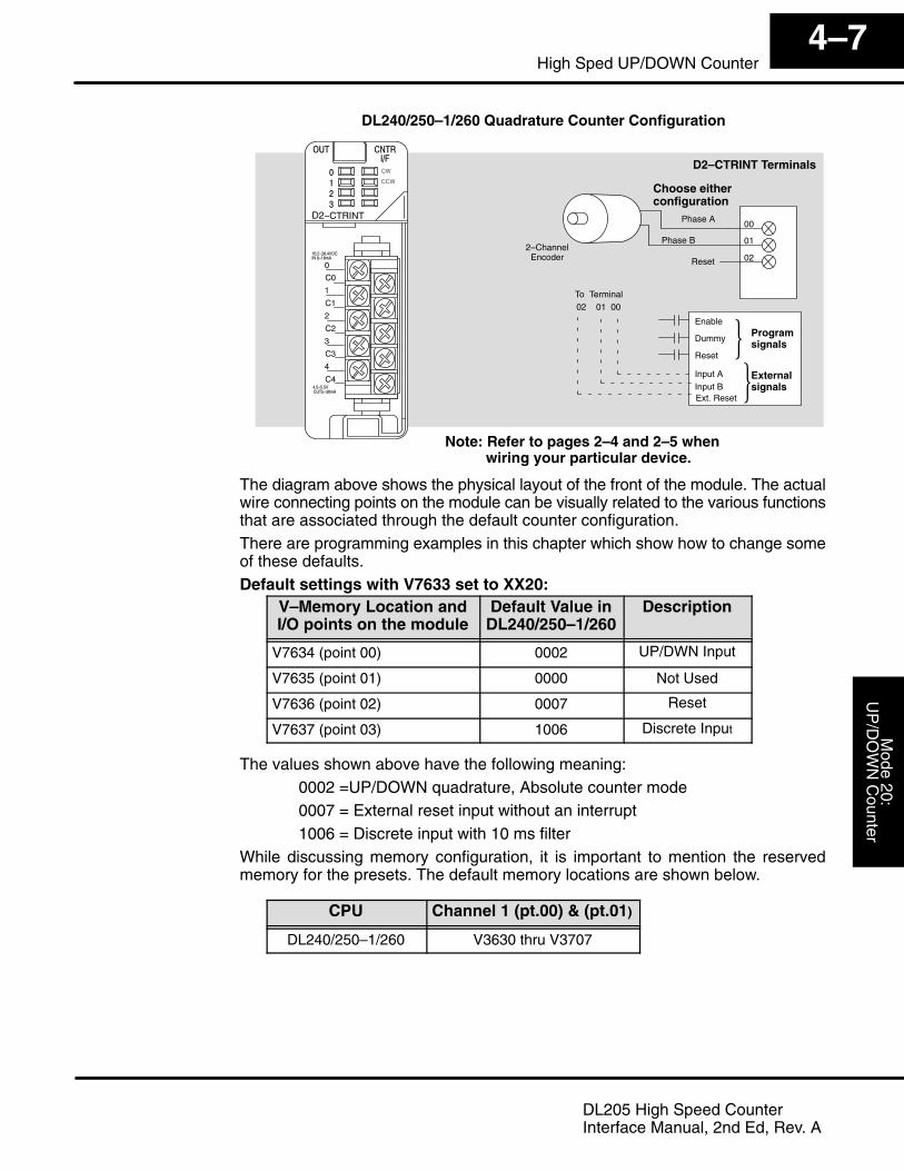
DL240/250–1/260 Quadrature Counter Configuration
Externalsignals
Programsignals
Reset
Dummy �
D2–CTRINT Terminals
00
02
01
Reset
Ext. Reset
�
02 01 00To Terminal
Phase A
Phase B2–Channel
Encoder
Choose eitherconfiguration
Note: Refer to pages 2–4 and 2–5 when wiring your particular device.
��
���
D2
The diagram above shows the physical layout of the front of the module. The actualwire connecting points on the module can be visually related to the various functionsthat are associated through the default counter configuration.There are programming examples in this chapter which show how to change someof these defaults.Default settings with V7633 set to XX20:
V–Memory Location andI/O points on the module
Default Value inDL240/250–1/260
Description
V7634 (point 00) 0002 UP/DWN Input
V7635 (point 01) 0000 Not Used
V7636 (point 02) 0007 Reset
V7637 (point 03) 1006 Discrete Input
The values shown above have the following meaning: 0002 =UP/DOWN quadrature, Absolute counter mode 0007 = External reset input without an interrupt 1006 = Discrete input with 10 ms filterWhile discussing memory configuration, it is important to mention the reservedmemory for the presets. The default memory locations are shown below.
CPU Channel 1 (pt.00) & (pt.01)
DL240/250–1/260 V3630 thru V3707

Mod
e 20
UP
/DO
WN
Cou
nter
Mod
e 20
:U
P/D
OW
N C
ount
er4–8
High Speed UP/DOWN Counter
DL205 High Speed CounterInterface Manual, 2nd Ed, Rev. A
Setting Up the CPU
The DL240/250–1/260 CPUs check the V-memory to see if there is a High SpeedCounter Interface Module present. There will be a hexadecimal number 10, 20, 30,40, 50 or 60 in V7633 if a module has been properly configured. This is the valuewhich is entered in the RLL program setup. If the CPU finds that a Counter InterfaceModule is present, other V-memory locations will be checked to see how each pointof the module has been configured.The values can be entered into memory by using either a handheld programmer orby editing them into a control program using DirectSOFT32. The followingexamples will show how to use DirectSOFT32 to configure the UP/DOWN Counter.The UP/DOWN Counter is Mode 20 which is the value to be set into V7633. Thefollowing DirectSOFT32 diagram shows the setup procedures for communicatingwith your DL240/250–1/260 PLC. Refer to the DirectSOFT32 Programmers UserManual for more details.
Setting theV-Memoryusing RLL
Setting theV-Memoryusing theMemoryEditor
Editing the D2–CTRINT setup at the beginning of the user program is the mostefficient method for setting up the counter mode. Should there be a need to changeany of the counter setup values after the PLC has been put in the RUN Mode, use theMemory Editor to change the values. These values will only be temporary. Theyshould be put into the program if they are to be used permanently.
Configuring theV–Memory
Step 1:Entering the ModeSelected

Mode 20
UP
/DO
WN
Counters
Mode 20:
UP
/DO
WN
Counter4–9
High Sped UP/DOWN Counter
DL205 High Speed CounterInterface Manual, 2nd Ed, Rev. A
The following RLL example shows how to set the UP/DOWN Counter, Mode 20, inV-memory location V7633.
DirectSOFT32 Display
LD
K0020
SP0
Load Mode 20 in Accumulator. The upper 4 bits are not being used.
OUT
V7633
Transfer Contents ofAccumulator to V7633
Two commands are needed to put the values into V-memory. The value must first beloaded into the accumulator of the CPU, then the CPU must transfer the value to thememory location. In this case, 20 is to be placed in V7633. This value is loaded intothe accumulator, LD K20. The CPU then writes this data to the memory location,V7633, once it reads the OUT command, OUT V7633. Notice that an SP0 contact isused in this rung. This relay is on for the first scan only. Thus, it will load the values inmemory initially, thereby keeping the scan time to a minimumThere are two different preset modes to chose from––either Absolute orIncremental. If the default Absolute mode of presets has been accepted, skip thisstep and go on to Step 3.To understand the concepts of using the Absolute and Incremental preset modes, itis essential to know some basics about the counter’s presets. Inside the PLC’smemory up to twenty–four (24) preset values can be setup for each counter. A presetis the number of pulses which are chosen to be counted before an event is to beinitiated.Presets are entered into successive areas of V-memory. With the Absolute mode,the presets are all independent. That is, the counter compares the actual total countreceived from the D2–CTRINT module to a preset, when the two are equal, the eventis triggered. With an Incremental preset mode, however, the presets are related toeach other. In such case, the counter reaches preset A and triggers event A, thenpreset B is added to preset A and that becomes the number of pulses that must becounted before event B is triggered. Preset C is added to the sum of presets A and Band that is the number of pulses required for event C to be triggered. The process ofadding all the presets continues until the CPU is notified that there are no morepresets to satisfy.
Step 2:Select thePreset Mode
Mod
e 20
UP
/DO
WN
Cou
nter
Mod
e 20
:U
P/D
OW
N C
ount
er4–10
High Speed UP/DOWN Counter
DL205 High Speed CounterInterface Manual, 2nd Ed, Rev. A
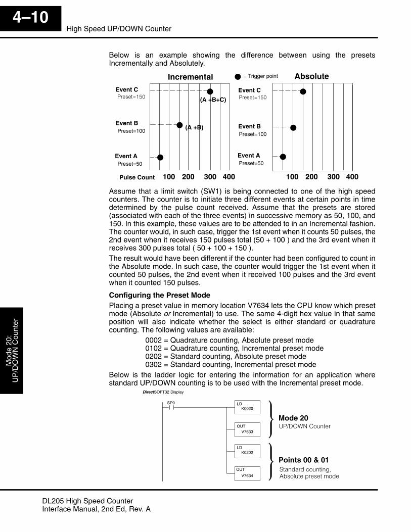
Below is an example showing the difference between using the presetsIncrementally and Absolutely.
� Pulse Count 100 200
Event A
Event B
Event C
Event A
Event B
Event C
�
�
�
�
�
�
Incremental Absolute
� ����*$%)
Preset=100
Preset=50
� ����*$%)
Preset=100
Preset=50
� = Trigger point
300 400 100 200 300 400
(A +B)
(A +B+C)
Assume that a limit switch (SW1) is being connected to one of the high speedcounters. The counter is to initiate three different events at certain points in timedetermined by the pulse count received. Assume that the presets are stored(associated with each of the three events) in successive memory as 50, 100, and150. In this example, these values are to be attended to in an Incremental fashion.The counter would, in such case, trigger the 1st event when it counts 50 pulses, the2nd event when it receives 150 pulses total (50 + 100 ) and the 3rd event when itreceives 300 pulses total ( 50 + 100 + 150 ).The result would have been different if the counter had been configured to count inthe Absolute mode. In such case, the counter would trigger the 1st event when itcounted 50 pulses, the 2nd event when it received 100 pulses and the 3rd eventwhen it counted 150 pulses.
Configuring the Preset ModePlacing a preset value in memory location V7634 lets the CPU know which presetmode (Absolute or Incremental) to use. The same 4-digit hex value in that sameposition will also indicate whether the select is either standard or quadraturecounting. The following values are available:
0002 = Quadrature counting, Absolute preset mode0102 = Quadrature counting, Incremental preset mode0202 = Standard counting, Absolute preset mode0302 = Standard counting, Incremental preset mode
Below is the ladder logic for entering the information for an application wherestandard UP/DOWN counting is to be used with the Incremental preset mode.
Points 00 & 01
DirectSOFT32 Display
LDK0020
SP0
OUTV7633
LDK0202
OUT
V7634
Mode 20
#��! !���������+,�������� �������!�
��������������

Mode 20
UP
/DO
WN
Counters
Mode 20:
UP
/DO
WN
Counter4–11
High Sped UP/DOWN Counter
DL205 High Speed CounterInterface Manual, 2nd Ed, Rev. A
The final step for setting up the CPU is to configure the presets. There are up to 24presets available for UP/DOWN counting. These presets can be changed in therelay ladder logic, but are only seen by the counter at a PLC mode change or reset ofthe counter.The presets are loaded into consecutive V-memory locations, starting with thedefault memory location of V3630. Use LDD and OUTD instructions as indicated inthe example below:
DirectSOFT32 Display
SP0
�
LDDK100
OUTDV3630
LDDK4000
OUTDV3632
LDDK12000
OUTDV3636
LDDK7500
OUTDV3634
First preset for first counterPreset=100
Second preset for first counterPreset=4000
Third preset for first counterPreset=7500
Fourth preset for first counterPreset=12000
Presets can be changed at any time; but in order for the counter to recognize thechanged values, the counter must be reset or the CPU must go through a modechange.Negative presets can be used, but in order to do so, the MSB in the upper word of thepreset must be made HIGH. Example: –250–1 = 80000250.Each of the presets are associated with special relays called equal relays. They canbe referenced in your relay ladder logic just like any other relay. Outside events aretriggered whenever the preset assigned to a particular relay is satisfied by the pulsecount, it closes. Unlike the UP counter Mode 10 (where there are two high speedcounters and two sets of equal relays ), there is only one UP/DOWN counter and oneset of equal relays for Mode 20.
DirectSOFT32 Display�
SP540 Y10OUT
SP541 Y11
SP542 C14
Equal relaysused to triggeroutside events.Can be used inmain program orin subroutines.
� �����-$�����
� �����-(�����
� �����-'�����OUT
OUT
SP543 Y13OUT
� �����-&�����
Step 3:The Presets
Loading thePresets
Using NegativePresets
Triggering Presetsto Outside Events
Mod
e 20
UP
/DO
WN
Cou
nter
Mod
e 20
:U
P/D
OW
N C
ount
er4–12
High Speed UP/DOWN Counter
DL205 High Speed CounterInterface Manual, 2nd Ed, Rev. A
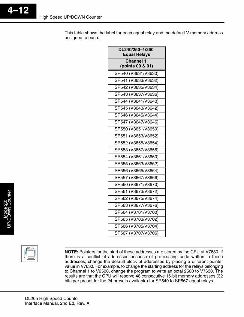
This table shows the label for each equal relay and the default V-memory addressassigned to each.
DL240/250–1/260 Equal Relays
Channel 1 (points 00 & 01)
SP540 (V3631/V3630)
SP541 (V3633/V3632)
SP542 (V3635/V3634)
SP543 (V3637/V3636)
SP544 (V3641/V3640)
SP545 (V3643/V3642)
SP546 (V3645/V3644)
SP547 (V3647/V3646)
SP550 (V3651/V3650)
SP551 (V3653/V3652)
SP552 (V3655/V3654)
SP553 (V3657/V3656)
SP554 (V3661/V3660)
SP555 (V3663/V3662)
SP556 (V3665/V3664)
SP557 (V3667/V3666)
SP560 (V3671/V3670)
SP561 (V3673/V3672)
SP562 (V3675/V3674)
SP563 (V3677/V3676)
SP564 (V3701/V3700)
SP565 (V3703/V3702)
SP566 (V3705/V3704)
SP567 (V3707/V3706)
NOTE: Pointers for the start of these addresses are stored by the CPU at V7630. Ifthere is a conflict of addresses because of pre-existing code written to theseaddresses, change the default block of addresses by placing a different pointervalue in V7630. For example, to change the starting address for the relays belongingto Channel 1 to V2500, change the program to write an octal 2500 to V7630. Theresults are that the CPU will reserve 48 consecutive 16-bit memory addresses (32bits per preset for the 24 presets available) for SP540 to SP567 equal relays.
Mode 20
UP
/DO
WN
Counters
Mode 20:
UP
/DO
WN
Counter4–13
High Sped UP/DOWN Counter
DL205 High Speed CounterInterface Manual, 2nd Ed, Rev. A
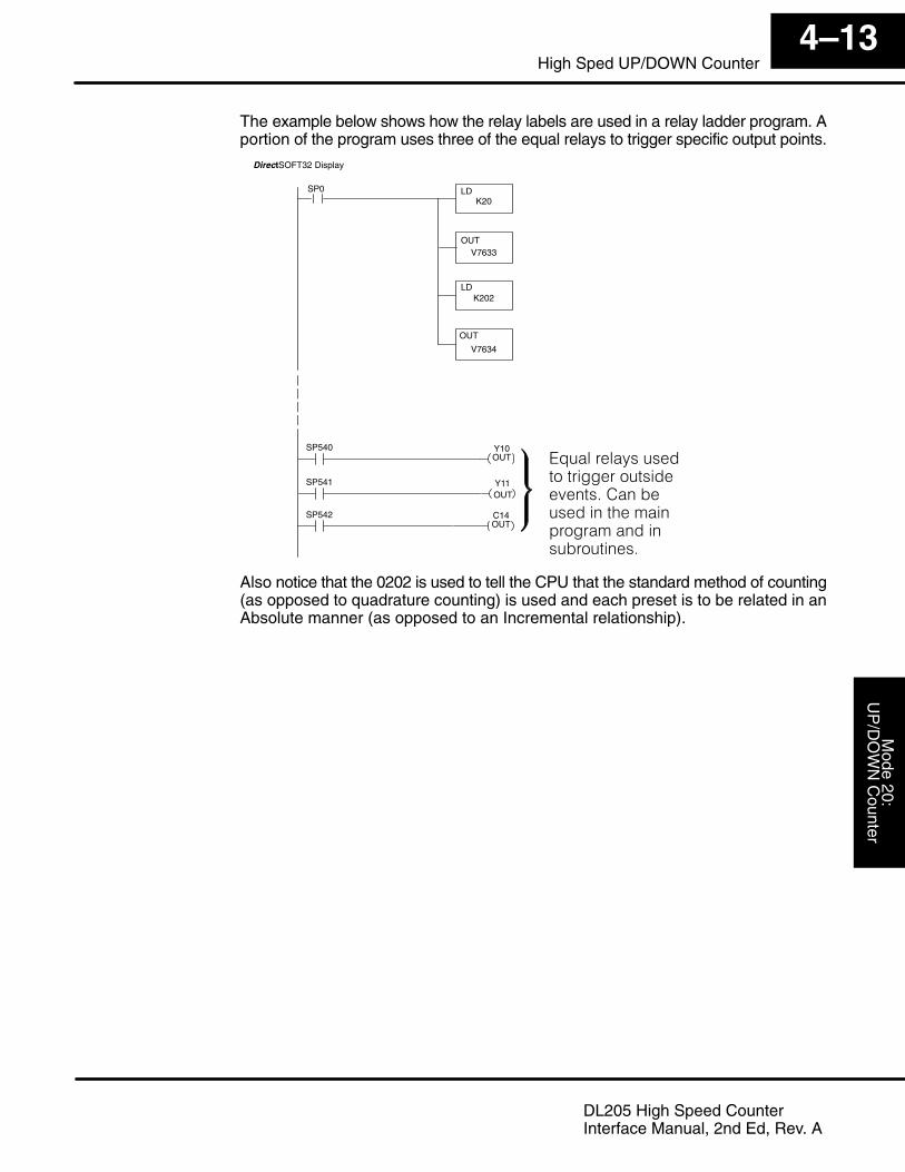
The example below shows how the relay labels are used in a relay ladder program. Aportion of the program uses three of the equal relays to trigger specific output points.
DirectSOFT32 Display
LDK20
SP0
OUTV7633
LDK202
OUT
V7634
SP540 Y10OUT
SP541
SP542 C14OUT
".��� ��/�����!���� ���� ������!��0��������������!����������� �� ���!������ ��������
Y11OUT
Also notice that the 0202 is used to tell the CPU that the standard method of counting(as opposed to quadrature counting) is used and each preset is to be related in anAbsolute manner (as opposed to an Incremental relationship).

Mod
e 20
UP
/DO
WN
Cou
nter
Mod
e 20
:U
P/D
OW
N C
ount
er4–14
High Speed UP/DOWN Counter
DL205 High Speed CounterInterface Manual, 2nd Ed, Rev. A
The Other Channels
When Mode 20 is selected, the CPU automatically writes the value of 1006 to V7637.The digits 06 means discrete input, and 10 selects a 10 ms filter. Point 03 is setup bydefault.Some applications have inputs from field devices which produce noise. Filtering canhelp to reduce or eliminate the noise from the inputs caused by switch bounce orother sources.When an input signal is first detected at point 03, a programmable filter is activatedwhich begins a timed countdown. The ON status of the signal is temporarilyprevented from being read by the input update of the CPU. The ON signal must staypresent for a certain amount of time for the filter to “time out”.Referring to the diagram below, once the signal has remained ON for the requiredtime, it is latched and allowed to be accepted by the CPU during the normal inputupdate of the PLC scan cycle. The signal is latched for the remaining duration of theON signal plus an amount of time equal to the filter time. The filter time can beprogrammed for 0 to 99ms in 1ms increments. It is set to 10 ms by default. Thefiltering time can be changed or a different function, Pulse Catching, can be selectedfor this input point.
Filter Time(0 to 99ms)
Latched Time
X0 (pt. 00)(External status)
(Internal status)
Signal is now allowed to beaccepted by the normal inputupdate of the PLC Scan Cycle
Filter Time(0 to 99ms)
Note: If zero is put in V-memory as the filter time. The CPU will treat the configurationas having no filter.
Filtered Input –Point 03
Discrete FilteredInputs

Mode 20
UP
/DO
WN
Counters
Mode 20:
UP
/DO
WN
Counter4–15
High Sped UP/DOWN Counter
DL205 High Speed CounterInterface Manual, 2nd Ed, Rev. A
When Mode 20 is selected, the CPU automatically writes 0007 to V7636. This valuerepresents a reset at point 02 without an interrupt. If the reset is to trigger aninterrupt, replace 0007 with 0107.An external reset with interrupt sets the counter to zero and allows temporarysuspension of the normal scan process in the main program while an interruptsubroutine is executed. When the subroutine is complete, the CPU automaticallyresumes its routine scan cycle, starting where it was interrupted. The followingdiagram illustrates the process. For a complete discussion of interrupts, readChapter 6.
���
���
1���� �� �
���� ��#�� ������
1���� �� �#����/�����
#�� ������#����/�����
2���!���0���
���� ��
������ 3�����
� �0�!���������� ��
Point 02 – Resetw/o an ExternalInterruptExternal Resetwith Interrupt

Mod
e 20
UP
/DO
WN
Cou
nter
Mod
e 20
:U
P/D
OW
N C
ount
er4–16
High Speed UP/DOWN Counter
DL205 High Speed CounterInterface Manual, 2nd Ed, Rev. A
Custom ConfigurationsUp to this point, only Mode 20 default settings have been discussed. The defaultsettings will be suitable for many applications, they will not require custom configuring.However, for those applications needing the defaults changed so the D2–CTRINT willwork for the applications, use the following table which contains the options available.
Mode 20 OptionsPoint Number V-Memory Definition (One per point) Hex Value
point 00 V7634 UP/DOWN Counter having 0002 (quadrature, Absolute) defaultpoint 00 V7634 UP/DOWN Counter havingPhase A (quadrature) or 1stEncoder (standard)
0102 (quadrature,Incremental)Encoder (standard)
0202 (standard, Absolute)
0302 (standard, Incremental)
1002 (quadrature, Absolute) 4xcounting*
1102 (quadrature, Incremental) 4x counting*
point 01 V7635 Phase B or 2nd Encoder InputDepending on value in V7634
0000 default
point 02 V7636 Reset UP/DOWN Counterdefault
0007** (no interrupt) default no Z pulse or index marker recogonition
0107 (interrupt) can recognize Z pulse or index marker
0207 (interrupt) no Z pulse or index marker recognition
0307 uses Z pulse recognition in the interrupt
Pulse Catcher 0005
Discrete Input xx06 (xx=filter time=0 to 99ms)
point 03 V7637 Discrete Input xx06 (xx=filter time=0 to 99ms)
Pulse Catcher 0005
point 04 Not Used Pulse Output (CCW) Not Used
Note: The lower byte of V7633 is set to 20.* This feature will allow the counter to count 4 times more with the same encoder (250–1/260 only).
Phase A
Phase B
Normal counting 1 2 3 4
1 2 3 4 5 6 7 8 10 119 12 13 14 15 164x counting
** In a high speed application using a high resolution encoder, with the CPU programmed with presetsthat span the resolution of the encoder, you may lose pulses in the higher range of presets.When using constants K7 or K107 in V7636 or V7637, the counter module will read thepreset V–memory each time the counter is reset or at the index marker location.When using K207 or K307, the counter module reads the preset V–memory only at powerup, or when a CPU mode change occurs (i.e. PROGRAM to RUN transition).
Mode 20CustomConfiguring

Mode 20
UP
/DO
WN
Counters
Mode 20:
UP
/DO
WN
Counter4–17
High Sped UP/DOWN Counter
DL205 High Speed CounterInterface Manual, 2nd Ed, Rev. A
Writing the Control Program for the UP/DOWN Counter
Once the UP/DOWN Counter has been configured, the control program can bewritten. Writing the RLL program for the high speed counter is much the same as fora regular counter. The embedded high speed counters which are activated throughthe D2–CTRINT module, have three inputs. The first input (Enable) allows countingwhen active. The middle input (Preload) allows you to change the current count. Thebottom input is to reset the counter. The preload input must be off while the counter iscounting.
Reset Input
DirectSOFT32
UDC CT174
K17688
Enable Input
Preload Input
1������4
��$5&
� �����3���4
–8388608 to +8388607
NOTE: To enter a negative number an 8 is placed in the most significant digit. Forexample: 80000570 entered in the preset gives a preset value of –570.
The mnemonic for the counter is UDC. It is found in the DirectSOFT32 instructionbrowser that pulls down using the hotkey F7 while in the Edit Mode. After selectingthe UDC, a box appears asking for the counter address and preset value. Thecounter address in the above example is CT174. The counter address for Mode 20 isalways 174. The preset value of 17688 has been used for this example. This is thenumber of pulses to be received before the output of the counter goes high. Anyvalue between –8,388,608 and +8,388,607 can be programmed for the preset. Afterentering the counter address and preset, enter the contact addresses for thecontacts which are automatically drawn in the RLL program.
DirectSOFT32
C10
K17688C10
SP1
UDC CT174
LDDKvalue
C10
OUTDCTA174
C10 is shown normally closed. When pulses arereceived at point 00, the current value in CTA174will increment. When pulses are received at point01, the current value will decrement. When C10energizes, CTA174 stops counting and Kvalue isloaded for a new preload value. When an input isreceived at point 02, the counter will reset.
When the Enable input is energized, the high speed counter will respond to pulses atpoint 00 and increment the counter. When pulses are received at point 01, thecounter will decrement. The reset input behaves in a logical OR fashion with thephysical reset input point 02. The high speed counter can receive a reset from eitherthe reset contact in the RLL or the external reset point 02 if it has been configured asan external input.

Mod
e 20
UP
/DO
WN
Cou
nter
Mod
e 20
:U
P/D
OW
N C
ount
er4–18
High Speed UP/DOWN Counter
DL205 High Speed CounterInterface Manual, 2nd Ed, Rev. A
Example 1: UP/DOWN Counting with an InterruptBelow is an example of how UP/DOWN counting with an interrupt can beprogrammed.
DirectSOFT32 Display
LDK20
SP0
OUTV7633
LDK202
OUTV7634
SP540 Y10OUT
SP541 Y11OUT
IRT
INT O0
SP1
K18724SP1
SP1
Interrupt Subroutine(Only Executed at External Reset)
UP/DOWN Counter
LDK107
OUT
V7636
External Reset w/Interrupt (02)See Step 4 on Page 12
Mode 20
Standard CountingAbsolute preset mode at 00 and 01
LDK2006
OUTV7637
Discrete Filtered Input at (03)20 ms. See Chapter 8
UDC CT174
LDDK5000
OUTDV3630
LDDK10000
OUTD
V3632
LDDKFFFF
OUTDV3636
LDDK15000
OUTDV3634
Presets for UP Counting
Tell CPU that thereare no more presets.(see page 3–16)
END
ENI
The load accumulator instructions have set up the V-memory as required, i.e. 20 inV7633 for the mode and 0202 in V7634 to designate a standard UP/DOWN counterwith the Absolute preset mode. By placing 0107 in V7636, an external reset forcounter 174 is selected and and it will execute interrupt 0 on the rising edge of thereset. Presets for UP/DOWN Counting have been stored in memory locationsV3630 through V3635. The next even-numbered memory location following this hasFFFF to indicate there are no more presets.

Mode 20
UP
/DO
WN
Counters
Mode 20:
UP
/DO
WN
Counter4–19
High Sped UP/DOWN Counter
DL205 High Speed CounterInterface Manual, 2nd Ed, Rev. A
Example 2: An UP/DOWN Counter with Standard InputsIn this example, assume there is a conveyor belt A that transports bottles to beinspected. During the course of the process, one sensor is keeping track of thebottles that are going onto belt A for inspection, and another sensor is keeping trackof how many bottles are being removed to the finished product line.When a quantity of 500 bottles has been reached in the process, an OVER 500 lightturns on and a re-routing gate is activated to channel the incoming bottles toconveyor belt B. The re-routing gate will stay activated for 30 seconds after theconveyor belt A contains less than 500 bottles.The program on the following page shows how the RLL program might be written forthe process. Note the use of V1174. This memory location stores the current countfor CT174 which is used with the D2-CTRINT.

Mod
e 20
UP
/DO
WN
Cou
nter
Mod
e 20
:U
P/D
OW
N C
ount
er4–20
High Speed UP/DOWN Counter
DL205 High Speed CounterInterface Manual, 2nd Ed, Rev. A
DirectSOFT32 Display
LDK20
SP0
OUTV7633
LDK202
OUTV7634
Y20
SP1
K500SP1
V1174
UP/DOWN Counter
Mode 20 (UP/DOWN counter)
Standard CountingAbsolute preset mode at 00 and 01
LDK1006
OUTV7637
Discrete Filtered Input at (03)10 ms. See Chapter 8
UDC CT174
External Reset without Interrupt (02)See Page 4–7
OUT
LDK7
OUT
V7636
LDK0
OUTV7635
Must be zero with mode 20
Only 1 counter is used with mode 20. The actualcount (32-bit) is stored in V1175/V1174. Whenpulses are received at point 00, the value inV1175/V1174 will increment. When pulses arereceived at point 01, the value in V1175/V1174will decrement.
SP1
When the pulse count reaches and exceeds450, the “over 450” light (Y20) will turn on.
K450
CT174 Y21OUT
C5SET
Over 450 light
Over 500 light
Over 500 latch
When the pulse count reaches and exceeds thepreset value of 500, the output of the counter(CT174) goes high and turns on the “over 500”light (Y21) and latches C5.
�
Actual Counts
Counter Output
END
Y22C5OUT
Over 500 latchWhen the count is 500 or over, the re-routinggate (Y22) turns on and will stay on until 30 se-conds after the count falls below 500.
re-routing gate
K300
TMRTIMER 0 OUTPUT
T0
CT174
C5T0RST
Over 500 latch
Timer 0 Output
Counter Output

Mode 20
UP
/DO
WN
Counters
Mode 20:
UP
/DO
WN
Counter4–21
High Sped UP/DOWN Counter
DL205 High Speed CounterInterface Manual, 2nd Ed, Rev. A
Example 3: Quadrature CountingIn this example, a wooden work piece is being drilled with three (3) holes. The holesare injected with glue for dowels to be inserted at another workstation. A quadratureencoder is connected to a positioning table which is moving a drill press horizontallyover the work piece. The positioning table will stop and the drill press will lower to drilla hole in the exact location. After the three (3) holes are drilled in the work piece, thepositioning table reverses direction and injects glue into the same holes.
The following program shows how this is done:
DirectSOFT32 Display
LDK20
SP0
OUTV7633
LDK2
OUTV7634
LDK107
OUTV7636
External Reset w/Interrupt (02)See Page 4–7
Mode 20
Quadrature CountingAbsolute mode at 00 and 01
LDK1006
OUTV7637
Discrete Filtered Input at (03)10 ms. See Chapter 8
LDDK5000
OUTDV3630
LDDK6000
OUTDV3632
LDDK7500
OUTD
V3634
Presets for UP Counting
There are nomore presets
LDK0
OUTV7635
ENI Enable interrupts
SP0
LDDK8000
OUTD
V3636
LDDKFFFF
OUTD
V3640
Continued on next page
This rung loads the counter’s presets.In this case, the Absolute presetmode has been selected.
Must be zero

Mod
e 20
UP
/DO
WN
Cou
nter
Mod
e 20
:U
P/D
OW
N C
ount
er4–22
High Speed UP/DOWN Counter
DL205 High Speed CounterInterface Manual, 2nd Ed, Rev. A
Y32V1174
OUT
During the reversing of the positioning table, theglue injection is turned on between pulse counts(7600–7499),(6100–5999),(5100–4999) beforeit reaches its home position and is reset to zeroby a limit switch (X2). NOTE: Presets can beadded to trigger outputs when counting DOWNas well as counting UP.
X20 Y30SET
C1RST
Glue injection
Forwarding positioning
table
Drilling sequencecompleted (one hole only)
The operator starts the drilling by moving thepositioning table forward. A quadrature encoderis transmitting the pulses to the D2-CTRINTmodule. After 5000 pulses are counted, thepositioning table is stopped and the drilling se-quence is started. Two more holes are neededin this work piece so the positioning and drillingare repeated twice automatically. (Stop and jogbuttons are left out here for simplicity but shouldbe incorporated in your logic.).
�
DirectSOFT32 Display
C1
Drilling sequencecompleted (one hole only)
Manual start of drillingprocess momentary PB
V1174
V1174
�
V1174
V1174
�
V1174
ReversingPosition Table
V3634 K7600
V3630
V3632
K5100
K6100
1st preset
2nd preset
3rd preset
SP1
K99999999SP1
UDC CT174
SP1
When the positioning table moves forward, thecurrent value in UDC174 increments. When thepositioning table moves backward, the valuedecrements.
C5 C6PD
Drilling sequence intiation One/shot bit
C6 Y20SET
Y21SET
Drill turning
One/shot bit
X10 Y20RST
Y22SET
Drill press up
Drill press down
Drill press downDrill fully extended.Limit switch 1
This rung initiates the drilling portion of our pro-gram. When C5 goes high the drill press is low-ered and the drill bit starts to turn.
When the drill has reached the proper depth,limit switch 1 (X10) is turned on and stops thedownward motion. This, in turn, raises the pressup with the drill bit still turning.
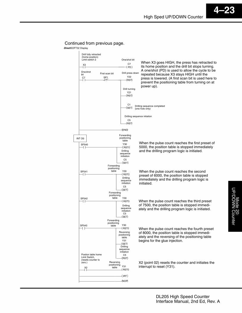
Continued from previous page.
Actual Counts
Actual Counts
Actual Counts
<
<
<
Y31
Mode 20
UP
/DO
WN
Counters
Mode 20:
UP
/DO
WN
Counter4–23
High Sped UP/DOWN Counter
DL205 High Speed CounterInterface Manual, 2nd Ed, Rev. A
X3 C7PD
When X3 goes HIGH, the press has retracted toits home position and the drill bit stops turning.A one/shot (PD) is used to allow the cycle to berepeated because X3 stays HIGH until thepress is lowered. (A first scan bit is used here toprevent the positioning table from turning on atpower up).
DirectSOFT32 Display
Continued from previous page.
Drill fully retracted(home position)Limit switch 2
C7 Y22RST
Y21RST
One/shotbit
Drill press down
C1SET
C5RST
SP1
One/shot bit
Drill turning
Drilling sequence completed(one hole only)
Drilling sequence intiation
SP540 Y30RSTI
INT O0
END
C5SET
SP541 Y30RSTI
C5SET
SP542 Y30RSTI
C5SET
SP543 Y30RSTI
Y31SET
C5RST
X2 Y31RSTI
IRT
NOP
When the pulse count reaches the first preset of5000, the position table is stopped immediatelyand the drilling program logic is initiated.
Forwardingpositioning
table
Drillingsequenceinitiation
Forwardingpositioning
table
Forwardingpositioning
table
Forwardingpositioning
table
Reversingpositioning
table
Drillingsequenceinitiation
Drillingsequenceinitiation
Drillingsequenceinitiation
Reversingpositioning
table
Positon table homeLimit Switch,(resets counter tozero.)
When the pulse count reaches the secondpreset of 6000, the position table is stoppedimmediately and the drilling program logic isinitiated.
When the pulse count reaches the third presetof 7500, the position table is stopped immedi-ately and the drilling program logic is initiated.
When the pulse count reaches the fourth presetof 8000, the position table is stopped immedi-ately and the reversing of the positioning tablebegins for the glue injection.
First scan bit
X2 (point 02) resets the counter and initiates theinterrupt to reset (Y31).
Mod
e 20
UP
/DO
WN
Cou
nter
Mod
e 20
:U
P/D
OW
N C
ount
er4–24
High Speed UP/DOWN Counter
DL205 High Speed CounterInterface Manual, 2nd Ed, Rev. A
Troubleshooting
After completing the configuration of the UP/DOWN counter for Mode 20, thecounter should work. If there is a problem with the counter operation, the informationbelow and on the following pages may provide some assistance in handling anyproblems if they should occur. Experience has shown that most problems occurbecause of improper configuration. Always re-check your CPU setup beforeanything else.For verifying types of inputs (or outputs) besides those related to UP/DOWNcounting, see the Chapters in this manual covering the specific function. Listedbelow are some things that could possibly go wrong with the UP/DOWN counterinputs:
1. The counter is not counting UP or DOWN when configured for standardUP/DOWN counting.
2. When configured for standard UP/DOWN counting, the UP counter seemsto be working, but there is no DOWN counting.
3. The status indicator LED is not lighting for the input point where theUP/DOWN counter is wired (i.e. points 00 and 01).
4. The counter does not appear to be counting synchronously with the inputdevice’s transitional states.
5. The counter is not resetting itself after it “counts out”.6. The counter is not jumping into its subroutine as expected when it reaches
a preset condition.7. The counter is counting properly and executing the interrupt properly, but
does not continue counting after the interrupt subroutine has beencompleted.
What Can GoWrong?

Mode 20
UP
/DO
WN
Counters
Mode 20:
UP
/DO
WN
Counter4–25
High Sped UP/DOWN Counter
DL205 High Speed CounterInterface Manual, 2nd Ed, Rev. A
You should be able to see counting taking place in the counter block while observingit in the monitor mode with DirectSOFT32. If this is not happening:
1. The CPU may be setup improperly. Check the RLL.2. The field device may be defective.3. The field device may be O.K., but it is too fast for the counter.4. The wiring may be defective.5. The input voltage may not be within specifications.6. The configuration may be improperly setup.7. The D2–CTRINT module is defective.
Defective Field Device - If a field device is suspected to be faulty, verify its properoperation first. Examine the characteristics of the pulses being received with anoscilloscope, test equipment type digital counter or an inexpensive logic probewhich has a pulse train input capability.
High Signal Indicator
Low Signal IndicatorPulse Train Indicator
Normal/Pulse Train Switch
TTL/CMOS Switch
Typical Low Cost Logic Probe
Connect power leads to your recommendedpower supply––not PLC power supply.
6Not available from AutomationDirect)Touch probe to outputpoints 03 and 04.
A rotary encoder could also be operating improperly because of a poor couplingbetween the encoder and the shaft of the motor. Check to make sure the coupling isnot defective. Check the specs on the field device. Be certain that it’s output signalmatches up with the specifications of the D2–CTRINT module.
Counter Doesn’tCount

Mod
e 20
UP
/DO
WN
Cou
nter
Mod
e 20
:U
P/D
OW
N C
ount
er4–26
High Speed UP/DOWN Counter
DL205 High Speed CounterInterface Manual, 2nd Ed, Rev. A
Too fast – The pulse rate cannot exceed 5 kHz. If this is suspect, try to slow down thepulse rate to see if the problem is solved. The pulse width may also be too narrow.The pulse must remain high for at least 100ms in order for the module to detect it.
Wiring - Simple as this might seem, quite often poor wiring is the cause of manyproblems. Make sure there is a complete electrical loop between the device and theinput module. Along with visual inspection, use a voltmeter to check this out.
Input Voltage - If the input device is producing a signal which is less than 12 volts,the counter will either not function properly or function improperly. Use a field devicewith the proper signal level if necessary.
Improper Configuration - The module may be looking for a counter which doesn’texist. Check the RLL program and be sure that the counter is addressed properly. Becertain that the inputs to the counter are properly configured. Is the counter enabled?This function is not available with the DL230.
Make sure the PWR or BAT LED’s are not lit on the CPU module. If either the batterypower or the external power indicators are not illuminated, there is either a defectivepower supply, the batteries are worn out or there is no power to the PLC.
Check to be certain that the status indicators are blinking as pulse signals arereceived at the proper input point on the module (i.e. 0 or 1). Check the field device tomake sure it is operating. Use an oscilloscope or digital counter to verify thepresence of a pulse train at the input point(s)) or use the Change Value feature inDirectSOFT32 to force the input point ON. Refer to the DirectSOFT32 SoftwareProgrammers Manual to use this feature. If after forcing the input ON, and theappropriate LED does not light, the module is defective..
WARNING: Take all necessary precautions to protect personnel and equipmentwhen forcing inputs and outputs, since the equipment on the output side of thesystem may be energized.
If the counter is subject of counting faster than the field device is sending pulses,then the interface may be experiencing noise. Try connecting a shielded wirebetween the field device and the module input. The wire should be shielded at oneend only-- normally the encoder side. If the PLC is interfaced to a rotary shaftencoder, a loose coupling could also be causing the problem. Check the coupling.
If a reset is not present when expected, check the configuration. Is the proper valuefor a reset being used? Is the module looking for an external reset? If so, is the fielddevice supplying the reset signal (which should be connected to either points 02)operating properly. Manually operate the reset device.
Is the interrupt subroutine labeled properly? The interrupt subroutine must belabeled Octal 0. Is there supposed to be an external interrupt, but the external deviceis not sending the signal? Does the external interrupt device meet the input criteria?Check all of these possibilities.
Does the interrupt subroutine end with an Interrupt Return instruction in the RLLprogram? Is there an endless loop inside the subroutine? Is there a conditionalreturn and the condition has not been met?
Rotary encoders can be classified both in terms of how they are coupled to therotating device for which they are providing information, and how they providepositional information. The rotary encoder can be mechanically coupled to the motorshaft, or it can be optically coupled internally to the encoder.
LED’s Do Not Light
Non–SynchronousPulsing
No Reset
Not Jumping toInterrupt
Not Returning fromInterrupt
Rotary Encoders