MODBUS-RTU communication - Mütec Instruments GmbH · 09/2019 Operating manual HUMY/SCS 3000...
21
09/2019 Operating manual HUMY/SCS 3000 MODBUS-RTU communication Mütec Instruments GmbH Tel.: +49 (0) 4185-80 83-0 e-Mail: [email protected] Bei den Kämpen 26 Fax: +49 (0) 4185-80 83-80 Web: www.muetec.de D-21220 Seevetal-Ramelsloh
Transcript of MODBUS-RTU communication - Mütec Instruments GmbH · 09/2019 Operating manual HUMY/SCS 3000...

09/2019
Operating manual HUMY/SCS 3000
MODBUS-RTU communication
Mütec Instruments GmbH Tel.: +49 (0) 4185-80 83-0 e-Mail: [email protected] Bei den Kämpen 26 Fax: +49 (0) 4185-80 83-80 Web: www.muetec.de D-21220 Seevetal-Ramelsloh

09/2019
_____________________________________________________________________________________________________________________
1
Operating manual for HUMY/SCS 3000
MODBUS-RTU communication No. BA 6.13 Date: 06/2014
Manufacturer:
Mütec Instruments GmbH Bei den Kämpen 26 21220 Seevetal Germany Tel.: +49 (0) 4185 8083-0 Fax: +49 (0) 4185 808380 E-Mail: [email protected] Internet: www.muetec.de Licence, trademark and copyright notes
Modbus™ is a registered trademark of Modicon Inc. Windows™ is a registered trademark of Microsoft Corp.
Copyright © Mütec Instruments GmbH 2010 All rights reserved
This document is copyright protected. It supports the user in making reliable and efficient use of the unit. Transmission and duplication of this document as well as utilization and disclosure of its content are prohibited unless expressly permitted. Any breach or infringement shall result in liability for damages. The software described in this document is licensed and may only be used and copied in accordance with the terms of the licence. All rights reserved. Disclaimer
We have checked the content of the printed document for compliance with the described hardware and software. Nevertheless, deviations cannot be excluded and consequently we cannot assume any guarantee for complete accordance. The data in this printed document are checked regularly. Corrections and additions are made in the following version in each case. We would be grateful for any suggestions for improvement. © Mütec Instruments GmbH Subject to technical modifications

09/2019
____________________________________________________________________________________________________________________
2
Contents
Classification of safety information …………………………………………… 3
General information ……………………………………………………………..… 4
1.0 Description of the HUMY/SCS 3000 ……………………………………….…… 5
2.0 Description of the sensor FMS 410 …………………………………………… 6
3.0 Housing/form of construction ………………………………………………….. 7
4.0 Data logger ………………………………………………………………………… 8
5.0 Technical Data of HUMY/SCS 3000 ……………………….….………………... 9
6.0 Technical Data of the HUMY- sensor FMS 410 ..….…...………………….... 12
7.0 Basic circuit diagram ……………………………………………………………. 13
8.0 Jumper-Settings …………………………………………………………………. 14
9.0 Cable connection of the HUMY-sensor ……….……………………………... 15
10.0 Terminal assignment for the 19“- desk housing……..……………………… 16
11.0 Assignment of the female connector for the 19“……..…..…………………. 17
12.0 Terminal assignment for the field-/wall housing ……….…………………… 18
13.0 Mounting instructions and installation examples ……….……..…………… 19

09/2019
____________________________________________________________________________________________________________________
3
Classification of the safety instructions
This manual contains instructions that you have to observe for your personal safety as well as to avoid material damage. These instructions are highlighted using a triangular warning sign and shown as follows, depending on the degree of risk.
HAZARD
means that death or severe physical injury will occur if the appropriate precautionary measures are not taken.
WARNING
means that death or severe physical injury may occur if the appropriate precautionary measures are not taken.
CAUTION
with a triangular warning sign means that minor physical injury may occur if the appropriate precautionary measures are not taken.
CAUTION
without a triangular warning sign means that material damage may occur if the appropriate precautionary measures are not taken.
ATTENTION
means that an undesired result or state may ensue if the corresponding instruction is not followed.
NOTE
denotes important information about the product, handling of the product or the respective part of the documentation, is aimed at drawing special attention to the latter and should be complied with.
In addition to the instructions in this manual, the generally applicable safety and accident prevention regulations must be observed. If the information contained in this document should not be sufficient in any specific case, you can obtain more detailed information from our telephone service. Please read this manual carefully prior to installation and commissioning.
CE mark
This product meets the specifications according to the EMC Directive 89/336/EEC and the Low Voltage Directive 73/23/EEC.
09/2019
____________________________________________________________________________________________________________________
4
General instructions
This device left the plant in flawless condition in terms of its safety features. To preserve this condition and ensure safe operation of the device, the user has to observe the instructions and warning notes indicated in this operating manual.
NOTE
For the sake of clarity the manual does not contain complete detailed information on all product types and can therefore not take into account every conceivable case with respect to installation, operation and maintenance. Should you wish further information or should special problems arise that are not treated in sufficient detail in the manual, you can obtain the necessary information by telephone. Moreover, we point out that the content of the manual shall not constitute part of or amend a previous or existing contract, agreement or legal relationship. All obligations of Mütec Instruments GmbH shall result from the respective contract of purchase, which also contains the complete and solely valid warranty terms. These contractual warranty terms shall neither be extended nor limited by the information contained in the manual. The content reflects the technical state of the art regarding printing. It is subject to technical modifications in the course of further development.
WARNING
Devices with the type of protection designated as “intrinsic safety” lose their conformity certification as soon as they have been operated in circuits that do not meet the values specified in the test certificate. Flawless and safe operation of this device requires proper transport, proper storage, installation and assembly as well as careful operation and maintenance. The device may only be used for the purposes specified in this operating manual.
DISCLAIMER
All modifications to the device fall within the responsibility of the user unless expressly specified otherwise in the operating manual. The delivered interface cable is not a standard cable. If using other or standard cable may occur problems and damage device.
Qualified PERSONNEL
are persons who are familiar with installation, assembly, repair and operation of the product and have
the qualifications necessary for their work, such as:
• Training, instruction and/or authorization to operate and maintain equipment/systems in accordance with the standards of safety technology for electrical circuits, high pressures and corrosive as well as hazardous media.
• In the case of equipment with explosion protection: training, instruction and/or authorization to perform work on electrical circuits for potentially explosive equipment.
• Training or instruction in accordance with the standards of safety technology regarding care and use of appropriate safety equipment.
CAUTION
Potentially electrostatic components may be destroyed by voltage that is far below the limits of human perception. Such voltage occurs even when you touch a component or electrical connections of a component and are not electrostatically discharged. The damage that occurs to a component because of overvoltage usually cannot be detected immediately and does not become noticeable until after a longer operating period.

09/2019
____________________________________________________________________________________________________________________
5
1.0 Description of the HUMY/SCS 3000
The HUMY/SCS 3000 system consists of the SCS 3000 19” module and the FMS 410 HUMY sensor. The inline measuring system for process monitoring guarantees trouble-free measurement of the internal product moisture of solids and emulsions. A graphic user interface with softkeys and a clearly arranged display of the measured, alarm and MIN/MAX values, combined with easy editing and parameterization, enables uncomplicated and simple operation.
Pic. 1
Features
QVGA-TFT- display and membrane keyboard with softkey support
Galvanic separated RS485 and RS232-interface
HUMY-WINSMART-program (optional) for MS-Windows®
Data logger (optional) for recording measurements with up to 1 GB flash memory
Real-time clock for time-stamping the measurement protocols
24 independent product settings
Analog drag indicator display for MIN/MAX values (thicker line width)
Digital representation of the MIN and MAX values as a percentage of the size
Direct analog band representation of the measurement
Threshold representation for the MIN and MAX alarm
Galvanic separated analog output for moisture
Galvanic separated analog output for temperature
2 galvanic separated digital inputs for an external regulation
2 galvanic separated digital output for MIN- and MAX-pre-alarm
2 relay contact outputs for MIN- und MAX-alarm
Pt100-input in 2-/3-wire circuit for product temperature compensation
mA-input for the product temperature compensation
Galvanic separated connection for the HUMY-sensor

09/2019
____________________________________________________________________________________________________________________
6
2.0 Description of the sensor FMS 410
The HUMY sensor for capacitive moisture measurement is based on the open capacitor principle. The bulk material in front of the measuring window serves as the dielectric of the measuring capacitor. Electronic processing of the measured value and temperature compensation in the sensor make it possible to securely transfer data over longer distances.
Pic. 2
The electronics installed behind the measuring window are encapsulated in a sturdy, hermetically sealed plastic case. Mounted in a solid cylindrical stainless steel housing, the sensor is extensively insensitive to external influences. Special internal casting protects the entire electronics against penetration of moisture and increases resistance to caustic solutions, acids and solvents. The power supply is provided via a fixed cable connection in the sensor and guarantees tightness to IP67 thanks to a high-quality PG cable gland. The thickness of the dielectric can vary between 20 and 100 mm and is determined by the type of bulk material. Electrical conductivity, pH value and surface structure hardly have any influence on the measurement, but do influence density. The measuring surface of the sensor is sensitive and has to be protected against mechanical impacts. In the case of special applications with high abrasion risk, the measuring surface can be reinforced by means of a built-in ceramic disk.
Features
20-bit measured value acquisition and measured value processing in the sensor
Automatic temperature compensation according to stored table
High degree of functional reliability combined with self-monitoring function
Low power input (≤ 350 mW)
Digital transmission of measured values immune to interference via RS485 interface
1000 m maximum cable length between sensor and HUMY 300
Sturdy cylindrical stainless steel flange housing
Little installation effort required for 4-core connecting line
Easy, space-saving installation

09/2019
____________________________________________________________________________________________________________________
7
3.0 Housing/Form of construction
For HUMY/SCS 3000 are 3 housing options available.
a) Housing F – Field housing/Wall mounting
Standard width 42TE, suitable for three HUMY 3019 Front view with transparent, protective door Protection class according to IEC 529 / EN 60529 - IP65 Cable inlet through five fittings Pg13,5 Housing material: AL Mg Si 0,5 Surface: Synthetic resin enamel finish RAL 7035 light gray
Dimensions: W = 265 mm, H = 240 mm, D = 250 mm
Pic. 3 Pic. 4
b) Form of construction T – Desk housing
Standard width 42TE, suitable for three HUMY 3019. Dimensions: W = 236 mm, H = 132 mm; D = 330 mm
Pic. 5
220
- B -
- C -

09/2019
____________________________________________________________________________________________________________________
8
c) Form of construction E – 19“-plugin
Standard width 42TE and 3 HE Dimensions: W = 213 mm, H = 128,2 mm; D = 176 mm
Pic. 6
4.0 Data logger
Optional, a data-logger function is available for HUMY 3000 and SCS 3000. This allows for permanent storage of computed measurements for moisture and temperature. Both, on-line data and archived data can be viewed for interpretation. A separately available Windows based download program allows transfer of data to a connected personal computer. Data can be viewed and analyzed with the Windows program Excel.
The following chart shows the maximum available time interval for data acquisition depending from the flash memory installed in the data-logger (triggering interval 5 sec.).
Pic. 7

09/2019
____________________________________________________________________________________________________________________
9
5.0 Technical Data of the HUMY/SCS 3000
Indicator: ¼ VGA-TFT-LCD (320 x 240 Pixel) 100 x 77 mm
Keyboard: 15 keys + 5 softkeys
Display: Date, time, kind of product temperature, value of residual, moisture or value of dehydrated substance, Min- and Max-alarm values, analog bar graph indication, dragging pointer, width of deviation of measuring value with intensified indication of width of deviation of measuring value, digital indication and description of Min-/Max-limit values and the softkeys
1. Measuring value: 0-85% residual moisture or 15-100% dehydrated substance Indicator: Percentage with max. 3 decimal places Accuracy: max. 0,2 % (depending on product) Average value: 0-999 sec.
2. Measuring value: Temperature of the sensor, measuring range from 0-5°C till 0-120°C Indicator: °C-value with 1 decimal place Accuracy: max. 0,1°C
Product memory: 24 products (optionally up to 100 products)
Data logger: Storage of moisture and temperature with time and date
Flash memory: 1 GB with 1 s scan rate results in a memory capacity for 2 years
For the analog outputs, a filter of the 1st order (0.1 – 9.9)s can be parameterized. Galvanic separation between the analog outputs, to the auxiliary energy and to all other inputs/outputs.
Constant current Voltage Max. range: 0...22 or 22...0 mA 0...11 or 11...0 V Standard range: 0/4-20 mA 0/2-10 V Load: max. 750 Ohm min. 50 kOhm Accuracy: 0,02 % of final value 0,02 % of final value Load influence: <0,005 % 0,5 % at RL=100 kΩ Rise time: <150 ms <150 ms
Galvanic separation between the contact outputs, to the auxiliary energy and to all other inputs/outputs.
Alarm number: 2 independently adjustable limit values Setting: %-value of moisture Alarm delay: free configurable from 0 ... 9,9 s Hysteresis: free configurable from 0 ... 99,9 % Operating mode: NO- or NC-principle Contact: Open and closed switch Switching power: max. 62,5 VA or max. 30 W Switching voltage: max. 125 V AC or 110 V DC Switching current: max. 1 A Min-contact voltage: 10 mVDC Min-contact current: 10 µA Contact material: AG Pd + 10 µAu Relay-Type: according to IEC 947-5-1 or EN60947
CONTACT OUTPUTS REL-1 (MAX-Alarm), REL-2 (MIN-Alarm)
ANALOG OUTPUT AA-1 (moisture), AA-2 (temperature)

09/2019
____________________________________________________________________________________________________________________
10
Galvanic separation between the transistor outputs, to the auxiliary energy and to all other inputs/outputs.
Alarm number: 2 independently adjustable limit values Setting: %-value of moisture Alarm delay: free configurable from 0 ... 9,9 s Hysteresis: free configurable from 0 ... 99,9 % Operating: NO- or NC-principle Output: Open Collector Switching power: <1,4 W Switching voltage: <28 VDC Switching current: <50 mA
Galvanic separation between the digital inputs, to the auxiliary energy and to all other inputs/outputs.
Direction of effect: direct or invers Control voltage: min. 8 VDC, max. 36 VDC Control current: min. 2 mA, max. 14 mA
For the two inputs, there is no galvanic separation from the inner circuitry.
Pt100-connection: 2 or 3-Lt.-switch Measuring range: 0°C to +100°C mA-range: 0/4 – 20 mA according to 0 – 100°C
Galvanic separation between the RS232/RS485 to the auxiliary energy and to all other inputs/outputs.
Protocol: MODBUS, RTU-Modus RS232/COM: via front socket connection at PC with Mütec-interface cable RS485: Half-duplex, termination with jumper Baudrate/device address: 2400-19200 bps, 1-248
Galvanic separation of the sensor to the auxiliary energy and to all other inputs/outputs.
Supply: 20 VDC, 20 mA RS485: Half-duplex Baudrate/ device address: 19200 bps, 1
Supply circuit-1: 115 or 230 VAC, - 15 % to +10 %, Change with Jumper at the VP 3000 – circuit board! Supply circuit -2: 24 VAC (50-60 Hz) or 24 VDC, +/- 25 % Power consumption: max. 6 W
For redundant power, the HUMY/SCS 2000 can also be run with both power supply circuits at the same time.
INTERFACES RS232, RS485
TRANSISTOR OUTPUTS DA-1 (MAX-pre-alarm), DA-2 (MIN-pre-alarm)
DIGITAL INPUTS DE-1 (diff. functions), DE-2 (diff. functions)
Pt100-INPUT / mA-INPUT AE-1 for ext. temperature compensation
HUMY-SENSOR-CONNECTION
AUXILIARY POWER

09/2019
____________________________________________________________________________________________________________________
11
EMV-directive 2004/108/EG: EN 61000-6-2, EN 61000-6-4, EN 61326-1
Accuracy Maximal: <0,2 % of final value Typical: <0,5 % of final value
Temperature coefficient Maximal: <0,05 %/K Typical: <0,03 %/K
Galvanic separation In-/Output/Supply: 300 Veff (rated insulation voltage, overvoltage II, Contamination
level 2, secure division according to EN 61010, EN 50178) Housing options
Form of construction T: Desk housing - weight ca. 4,5 kg W=236 x H=132 x D=330 mm
Form of construction F: field housing-/ wall mounting (IP65) with transparent door W=265 x H=240 x D=290 mm, weight ca. 6,5 kg Form of construction E: 19“- 3HE/42TE, weight ca. 2 kg Form of construction S: Control panel housing (IP58) with transparent door W=270 x H=183 x D=223 mm, weight ca. 3 kg
Electrical connection Form of construction T: Screw-plug in connection/green with 2,5 mm2 Form of construction F: screw connection/green with 2,5 mm2
Form of construction E: Female connector (32/48-polig) according to DIN 41612 – Housing F
Housing protection class Form of construction T: IP20 according to EN 60529 Form of construction F: IP65 according to EN 60529 Form of construction E: IP20 according to EN 60529
Ambient conditions Permissible temperature: -10 °C ... +60 °C Storage/transport: -10 °C ... +70 °C Permissible humidity while operation: 10 % … 95 % r.F. without condensation
To connect the SCS3000 with one or more HUMY3019 is optionally an additional galvanic separated RS485-full duplex-interface available.
Pic. 8
GENERAL DATA
CONFORMITY
SCS3000 with HUMY3019 in Master-Slave-Mode
09/2019
____________________________________________________________________________________________________________________
12
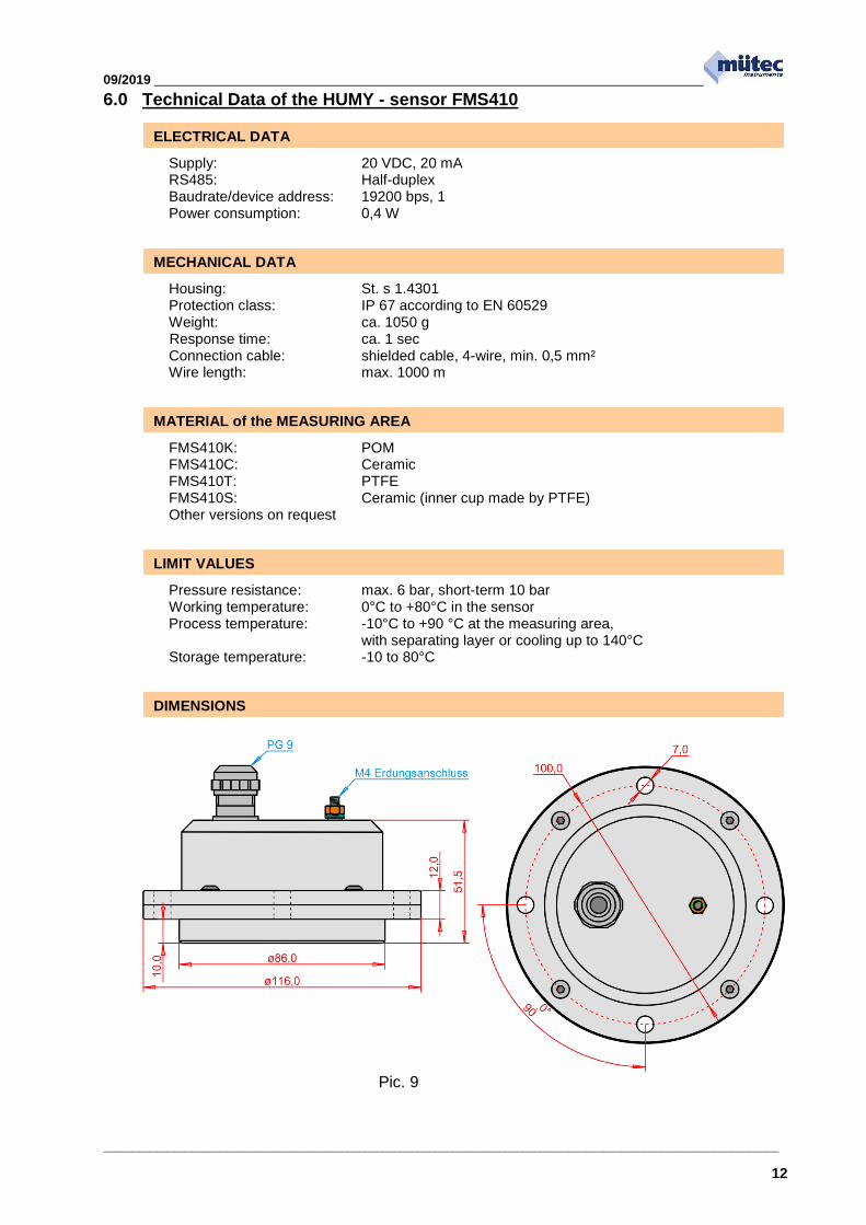
6.0 Technical Data of the HUMY - sensor FMS410
Supply: 20 VDC, 20 mA RS485: Half-duplex Baudrate/device address: 19200 bps, 1 Power consumption: 0,4 W
Housing: St. s 1.4301 Protection class: IP 67 according to EN 60529 Weight: ca. 1050 g Response time: ca. 1 sec Connection cable: shielded cable, 4-wire, min. 0,5 mm² Wire length: max. 1000 m
FMS410K: POM FMS410C: Ceramic FMS410T: PTFE FMS410S: Ceramic (inner cup made by PTFE) Other versions on request
Pressure resistance: max. 6 bar, short-term 10 bar Working temperature: 0°C to +80°C in the sensor Process temperature: -10°C to +90 °C at the measuring area, with separating layer or cooling up to 140°C Storage temperature: -10 to 80°C
Pic. 9
ELECTRICAL DATA
MECHANICAL DATA
MATERIAL of the MEASURING AREA
DIMENSIONS
LIMIT VALUES

09/2019
____________________________________________________________________________________________________________________
13
7.0 Basic circuit diagram
Pic. 10

09/2019
____________________________________________________________________________________________________________________
14
8.0 Jumper-Settings
1. Termination of the RS485-interface: For termination of the RS485-interface, the jumpers JP1/JP2 have to be closed.
2. Switching the analog outputs from constant current to voltage: The jumper JP3 for AA1 or JP4 for AA2 switches from constant current (JP3/JP4 open) to voltage (JP3/JP4 closed).
Fig. 9 Pic. 11
3. Switching the power voltage: 230 VAC or 115 VAC 230 VAC: Jumper JP1 closed, JP2+JP3 opened 115 VAC: Jumper JP1 opened, JP2+JP3 closed
Pic. 12
Fig. 10

09/2019
____________________________________________________________________________________________________________________
15
9.0 Cable connection of the HUMY - sensor
The cable shield is connected to the ground contact in the sensor. If the cable shield is also grounded at the other end of the line and there is a significant potential difference between the two grounding points, the result is a considerable flow of compensating current via the cable shield with all related impacts.

09/2019
____________________________________________________________________________________________________________________
16
10.0 Terminal assignment for the 19“ - desk housing
Pic. 14

09/2019
____________________________________________________________________________________________________________________
17
11.0 Assignment of the female connector for the 19“
Rear view at the Humy/SCS3000
Pic. 15
09/2019
____________________________________________________________________________________________________________________
18
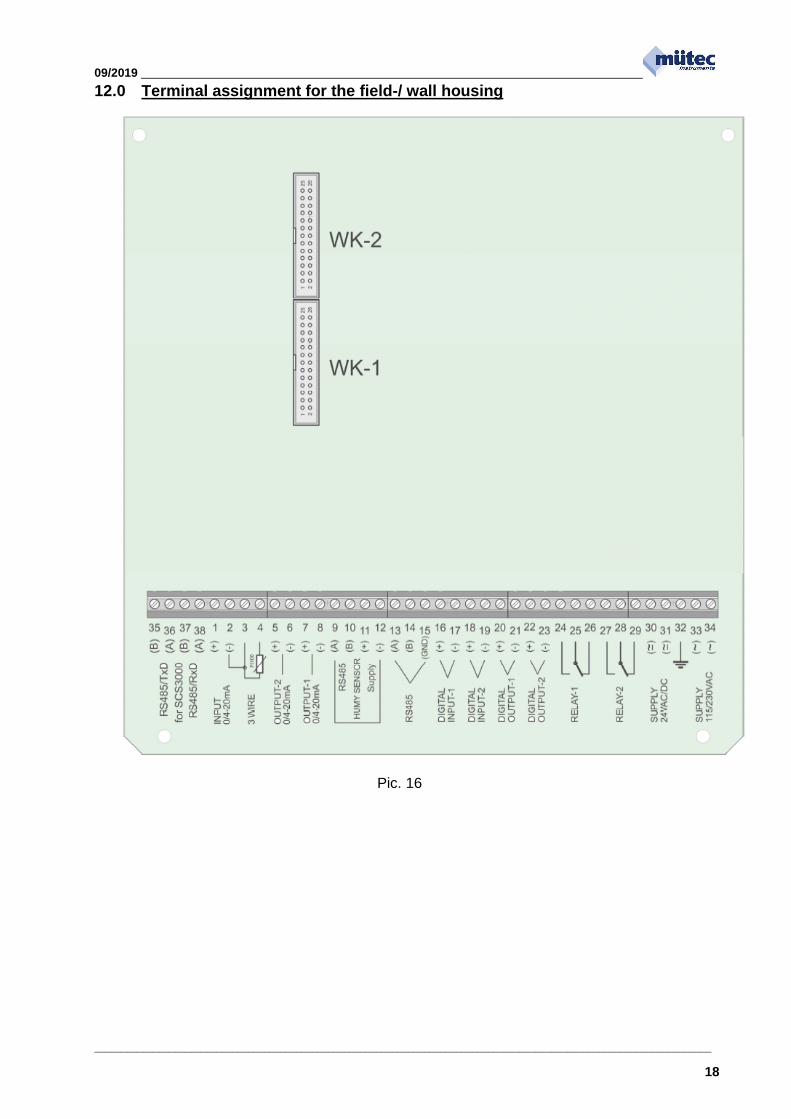
12.0 Terminal assignment for the field-/ wall housing
Pic. 16

09/2019
____________________________________________________________________________________________________________________
19
13.0 Mounting instructions and installation examples
The HUMY 3000 is designed for continuous moisture measurement in production flow. A prerequisite for correct moisture measurement in bulk materials is always to select the right place to install the moisture sensor. In connection with bulk material chutes or conveyor belts, you additionally have to ensure that the material to be measured is fed over the sensor at a constant layer height as far as possible.
13.1 Mounting in a screw conveyor
Mounting the moisture sensor in the spiral conveyer has proven to be particularly advantageous since the measured product is guided over the sensor at regular intervals with a constant thickness. The moisture sensor has to be placed underneath the screw conveyor.
Meß gut
go ods for m eas urin g
E in bau ort de r S ond e
l oca ti on o f se nso r
S ond e / se nso r
20 b is 4 5°
Pic. 17
20° - 30°
40 / 60 mm
Wand des SchneckenförderersSchnecken-
wendel
Es ist auch möglich, einen Gummiabstreifer am Wendelzu montieren.
abgeschnittener
Wendelteil
Pic. 18
In the case of hard bulk materials, the sensor surface is subject to a latent risk of material getting stuck between the screw conveyor and the HUMY sensor. This can be prevented here by cutting off the spiral. As a substitute for the cut-off spiral, you can install a rubber scraper that then performs the function of material transport.

09/2019
____________________________________________________________________________________________________________________
20
13.2 Indirect mounting
Indirect installation of the HUMY sensor is necessary if the wall thickness is 10 mm or more or the wall is curved. In such cases use of a welded flange is recommended.
Pic. 19
13.3 Mounting at a measurement window or separation layer
For most applications direct contact of the sensor surface with the product is desired. In some applications this might not be possible / suitable. Here, a neutral separator layer made out of Plexiglas, glass, or similar material can be fitted between sensor and product. A metallic separator layer is NOT permitted. Maximum thickness of the separator material is 30 mm.
Pic. 20
bulk material 90 - 130°C
Use of a separating layer of 5 to 15 mm is recommended with chain conveyors or for measurements with media having a temperature of over 80°C up to max. 130°C. The permissible thickness depends on the material to be measured and the residual water content. The measuring surface of the moisture sensor must always have mechanical contact to the separating layer.