MODBUS Protocol for CS141 - ups.legrand.com · MODBUS is a protocol for serial communication. Data...
23
Last update: 25/02/2020 1 MODBUS Protocol for CS141 network card family Summary 1. MODBUS PROTOCOL ............................................................................................................. 2 1.1. MODBUS COMMUNICATION PARAMETERS.......................................................................................... 2 1.2. AVAILABLE MODBUS FUNCTION CODES.............................................................................................. 2 1.3. EXCEPTION CODES ......................................................................................................................... 3 2. COMMUNICATION EXAMPLE ................................................................................................. 4 3. MODBUS TABLES ................................................................................................................... 6 3.1. NIKY, NIKY S, KEOR LINE RT........................................................................................................... 6 3.2. DAKER DK, DAKER DK PLUS, KEOR LP, KEOR S ................................................................................ 8 3.3. DHEA, WHAD 800/1000/1500/2000/2500, WHAD CAB, MEGALINE ........................................... 10 3.4. WHAD 3000/6000, TRIMOD, TRIMOD HE, ARCHIMOD, ARCHIMOD HE ........................................... 12 3.5. KEOR T, KEOR T EVO COMPACT, KEOR T EVO, KEOR T 208V .......................................................... 14 3.6. KEOR HP ................................................................................................................................... 16 3.7. KEOR HPE ................................................................................................................................. 18 3.8. KEOR MOD ............................................................................................................................... 20 3.9. STATUS BYTES TABLE ( SEE REGISTRY 109 OF ALL PREVIOUS TABLES ) ..................................................... 22 4. APPENDIX ............................................................................................................................ 23 4.1. RS485 CONNECTOR FOR CS141M AND CS141M SK ....................................................................... 23 4.2. BUS TERMINATION ....................................................................................................................... 23
Transcript of MODBUS Protocol for CS141 - ups.legrand.com · MODBUS is a protocol for serial communication. Data...

Last update: 25/02/2020
1
MODBUS Protocol
for CS141 network card family
Summary
1. MODBUS PROTOCOL ............................................................................................................. 2
1.1. MODBUS COMMUNICATION PARAMETERS.......................................................................................... 2
1.2. AVAILABLE MODBUS FUNCTION CODES.............................................................................................. 2
1.3. EXCEPTION CODES ......................................................................................................................... 3
2. COMMUNICATION EXAMPLE ................................................................................................. 4
3. MODBUS TABLES ................................................................................................................... 6
3.1. NIKY, NIKY S, KEOR LINE RT........................................................................................................... 6
3.2. DAKER DK, DAKER DK PLUS, KEOR LP, KEOR S ................................................................................ 8
3.3. DHEA, WHAD 800/1000/1500/2000/2500, WHAD CAB, MEGALINE ........................................... 10
3.4. WHAD 3000/6000, TRIMOD, TRIMOD HE, ARCHIMOD, ARCHIMOD HE ........................................... 12
3.5. KEOR T, KEOR T EVO COMPACT, KEOR T EVO, KEOR T 208V .......................................................... 14
3.6. KEOR HP ................................................................................................................................... 16
3.7. KEOR HPE ................................................................................................................................. 18
3.8. KEOR MOD ............................................................................................................................... 20
3.9. STATUS BYTES TABLE ( SEE REGISTRY 109 OF ALL PREVIOUS TABLES ) ..................................................... 22
4. APPENDIX ............................................................................................................................ 23
4.1. RS485 CONNECTOR FOR CS141M AND CS141M SK ....................................................................... 23
4.2. BUS TERMINATION ....................................................................................................................... 23

2
1. Modbus Protocol
MODBUS is a protocol for serial communication. Data is transmitted in form of 16bit registers (integer) or data byte status information. It is an open protocol and a common protocol in industry machinery. The fundamental structure of MODBUS has never changed due to compatibility reasons. MODBUS is also a single mater protocol. The master controls the whole transmission and monitors potential occurring timeouts. The connected devices are only allowed to send telegrams if the master requests. For remote control and monitoring of devices the MODBUS interface in each CS141 can read out measurement values, events, status and other information in a master-slave protocol.
1.1. Modbus Communication Parameters
The CS141 always uses 8 data bits for communication. If you receive faulty answers (Timeout Errors, Transaction ID Errors, Write Errors etc.), it may be, that the polling cycle was defined to fast. This causes the non-answered polling requests or even to a reboot of the CS141 through the integrated Watchdog, because the system is overloaded. Further on it can come to delayed answers during the MODBUS over IP or rather RS485 polling due to traffic into the bus or network, because the CS141 is a multi-device, which has to handle several tasks at the same time. Please define a response timeout of at least 500ms (at a fast MODBUS over IP or RS485 network/bus or rather higher accordingly, e.g. 4000ms at slow connections). The timeout has to be increased until the errors stay out.
1.2. Available Modbus Function Codes
Implemented MODBUS functions in the CS141 units:
Code Original Modbus Function
03H Read Holding Registers
04H Read Input Registers
10H Write Multiple Registers
The CS141 makes no difference between function 03H and 04H. The baud rate is adjustable up to 38400 Baud. Please note that the MODBUS adapter client allows a timeout of 40ms at 9600 baud for one value.

3
1.3. Exception Codes
Except for broadcast messages, when a master device sends a query to a slave device it expects a normal response. One of four possible events can occur from the master's query:
• If the slave device receives the query without a communication error, and can handle the query normally, it returns a normal response.
• If the slave does not receive the query due to a communication error, no response is returned. The master program will eventually process a timeout condition for the query.
• If the slave receives the query, but detects a communication error parity, LRC, or CRC, no response is returned. The master program will eventually process a timeout condition for the query.
• If the slave receives the query without a communication error, but cannot handle it (for example, if the request is to read a non existent register the slave will return an exception response informing the master about the nature of the error.
Available Exception codes:
Code Meaning
01H Illegal: The command received in the query is not defined.
02H Illegal: The address received in the query is not defined for the slave.
04H Slave device failure: Internal slave device error

4
2. Communication Example
The following tables contain the general command descriptions and examples with Modbus RTU framing. Query:
slave no function code address of first word to read
word count Checksum LRC or CRC
1 byte 1 byte High byte Low byte High byte Low byte 1 or 2 bytes
Answer:
slave no function code byte count high byte of first word
low byte of first word
bytes with contents of “n” words
Checksum LRC or CRC
1 byte 1 byte 1 byte 1 byte 1 byte n * 2 bytes 1 or 2 bytes
Read Words (Functions 03h and 04h) Example: Read Words, Function 04h Read one word at address 63h (= 99 decimal):
Query:
Byte 1 2, 3 4, 5 6, 7 8, 9 10, 11 12, 13 14, 15 16 17
Meaning Leading colon
Slave number
Function code
Address of first word to read
Word count to read
LRC Carriage return
Line feed LF high byte low byte high byte low byte
HEX [3A] [30][31] [30][34] [30][30] [36][33] [30][30] [30][31] [39][37] [0D] [0A]
Answer:
Byte 1 2, 3 4, 5 6,7 8, 9 10, 11 12, 13 14 15
Meaning Leading colon
Slave number
Function code
Byte count
Contents of the word
LRC Carriage return
Line feed LF
high byte low byte
HEX [3A] [30][31] [30][34] [30][32] [31][32] [33][34] [42][33] [0D] [0A]
HEX: Hexadecimal values of the data → The word at address contains the value 1234h = 4660 decimal. Example: Read Words, Function 04h, RTU Mode Read one word at address 63h (= 99 decimal) ( The word at address contains the value 1234h = 4660 decimal.): Query:
Byte 1 2 3 4 5 6 7 8
Meaning silent interval >= 3,5 characters
slave number
function code
address of first word to read
word count to read
CRC silent interval >= 3,5 characters
high byte
low byte
high byte
low byte
low byte
high byte
RTU HEX
[01] [04] [00] [63] [00] [01] [C1] [D4]
Answer:

5
Byte 1 2 3 4 5 6 7
Meaning silent interval >= 3,5 characters
slave number
function code
byte count
contents of the word
CRC silent interval >= 3,5 characters
high byte low byte low byte high byte
RTU HEX
[01] [04] [02] [12] [34] [B4] [47]

6
3. Modbus Tables
Note: “Type U/S”: this defines whether the answer has an algebraic sign (math. +/-) or not.
U means “unsigned”. S means “signed”, so this answer may be positive or negative. The answer may be true or false. Some clients (f.e. MODBUS Poll) use MODBUS addresses with a valid range between 0-65535. Some clients use as the valid range 1-65536, so it may be necessary to add 1 to the address.
3.1. Niky, Niky S, Keor Line RT
Address Type Function Description Length Notes
97 U 3 / 4 Output Voltage [V] 1
100 U 3 / 4 Output Power [%] 1
103 U 3 / 4 Battery Charge Level [%] 1
104 S 3 / 4 Input Voltage [V] 1
107 S 3 / 4 Temperature [C°] 1
108 S 3 / 4 Autonomy Time [minutes] 1
109 U 3 / 4 UPS Status (ASCII HEX) Please check “Status Bytes table“ below
1
110 S 3 / 4 Battery Voltage [V] 1
111 U 3 / 4 Input Frequency [Hz] 1
114 U 3 / 4 Powerfail Counter 1
116 U 3 / 4 Alarm: On Battery 1 = active; 0 = not active
1
117 U 3 / 4 Alarm: Battery Low 1 = active; 0 = not active
1
119 U 3 / 4 Alarm: Over Temperature 1 = active; 0 = not active
1
122 U 3 / 4 Alarm: Output Overload 1 = active; 0 = not active
1
132 U 3 / 4 Alarm: General Fault 1 = active; 0 = not active
1
134 U 3 / 4 Alarm: UPS communication lost 1 = active; 0 = not active
1
138 U 3 / 4 Alarm: Test in progress 1 = active; 0 = not active
1
139 U 3 / 4 AUX Port 1 1 = active (high); 0 = not active (low)
1 (1)
140 U 3 / 4 AUX Port 2 1 = active (high); 0 = not active (low)
1 (1)
141 U 3 / 4 AUX Port 3 1 = active (high); 0 = not active (low)
1 (1)
142 U 3 / 4 AUX Port 4 1 = active (high); 0 = not active (low)
1 (1)
143 U 3 / 4 Sensormanager / SM_T_COM sensor 1 Analog value
1 (2)
144 U 3 / 4 Sensormanager / SM_T_COM sensor 2 Analog value
1 (2)

7
145 U 3 / 4 Sensormanager sensor 3 Analog value
1 (2)
146 U 3 / 4 Sensormanager sensor 4 Analog value
1 (2)
147 U 3 / 4 Sensormanager sensor 5 Analog value
1 (2)
148 U 3 / 4 Sensormanager sensor 6 Analog value
1 (2)
149 U 3 / 4 Sensormanager sensor 7 Analog value
1 (2)
150 U 3 / 4 Sensormanager sensor 8 Analog value
1 (2)
(1) not available in CS141B, CS141B SK
(2) available only in CS141, CS141 SK

8
3.2. Daker DK, Daker DK Plus, Keor LP, Keor S
Address Type Function Description Length Note
97 U 3 / 4 Output Voltage [V] 1
100 U 3 / 4 Output Power [%] 1
103 U 3 / 4 Battery Charge Level [%] 1
104 S 3 / 4 Input Voltage phase L1 [V] 1
105 S 3 / 4 Input Voltage phase L2 [V] 1 (1)
106 S 3 / 4 Input Voltage phase L3 [V] 1 (1)
107 S 3 / 4 Temperature [C°] 1
108 S 3 / 4 Autonomy Time [minutes] 1
109 U 3 / 4 UPS Status (ASCII HEX) Please check “Status Bytes table“ below
1
110 S 3 / 4 Battery Voltage [V] 1
111 U 3 / 4 Input Frequency phase L1 [Hz] 1
112 U 3 / 4 Input Frequency phase L2 [Hz] 1 (1)
113 U 3 / 4 Input Frequency phase L3 [Hz] 1 (1)
114 U 3 / 4 Powerfail Counter 1
116 U 3 / 4 Alarm: On Battery 1 = active; 0 = not active
1
117 U 3 / 4 Alarm: Battery Low 1 = active; 0 = not active
1
119 U 3 / 4 Alarm: Over Temperature 1 = active; 0 = not active
1
122 U 3 / 4 Alarm: Output Overload 1 = active; 0 = not active
1
123 U 3 / 4 Alarm: On Bypass 1 = active; 0 = not active
1
132 U 3 / 4 Alarm: General Fault 1 = active; 0 = not active
1
134 U 3 / 4 Alarm: UPS communication lost 1 = active; 0 = not active
1
138 U 3 / 4 Alarm: Test in progress 1 = active; 0 = not active
1
139 U 3 / 4 AUX Port 1 1 = active (high); 0 = not active (low)
1 (2)
140 U 3 / 4 AUX Port 2 1 = active (high); 0 = not active (low)
1 (2)
141 U 3 / 4 AUX Port 3 1 = active (high); 0 = not active (low)
1 (2)
142 U 3 / 4 AUX Port 4 1 = active (high); 0 = not active (low)
1 (2)
143 U 3 / 4 Sensormanager / SM_T_COM sensor 1 Analog value
1 (3)
144 U 3 / 4 Sensormanager / SM_T_COM sensor 2 Analog value
1 (3)
145 U 3 / 4 Sensormanager sensor 3 Analog value
1 (3)
146 U 3 / 4 Sensormanager sensor 4 Analog value
1 (3)

9
147 U 3 / 4 Sensormanager sensor 5 Analog value
1 (3)
148 U 3 / 4 Sensormanager sensor 6 Analog value
1 (3)
149 U 3 / 4 Sensormanager sensor 7 Analog value
1 (3)
150 U 3 / 4 Sensormanager sensor 8 Analog value
1 (3)
(1) available only in three-phase UPSs
(2) available only in CS141, CS141 SK
(3) not available in CS141B, CS141B SK

10
3.3. Dhea, Whad 800/1000/1500/2000/2500, Whad CAB, Megaline
Address Type Function Name Length Notes
97 U 3 / 4 Output Voltage [V] 1
100 U 3 / 4 Output Power [%] 1
103 U 3 / 4 Battery Charge Level [%] 1
104 S 3 / 4 Input Voltage [V] 1
107 S 3 / 4 Temperature [C°] 1
108 S 3 / 4 Autonomy Time [minutes] 1
109 U 3 / 4 UPS Status (ASCII HEX) Please check “Status Bytes table“ below
1
110 S 3 / 4 Battery Voltage [V] 1
114 U 3 / 4 Powerfail Counter 1
116 U 3 / 4 Alarm: On Battery 1 = active; 0 = not active
1
117 U 3 / 4 Alarm: Battery Low 1 = active; 0 = not active
1
119 U 3 / 4 Alarm: Over Temperature 1 = active; 0 = not active
1
122 U 3 / 4 Alarm: Output Overload 1 = active; 0 = not active
1
123 U 3 / 4 Alarm: On Bypass 1 = active; 0 = not active
1
127 U 3 / 4 Alarm: Charger failed 1 = active; 0 = not active
1
132 U 3 / 4 Alarm: General Fault 1 = active; 0 = not active
1
134 U 3 / 4 Alarm: UPS communication lost 1 = active; 0 = not active
1
138 U 3 / 4 Alarm: test in progress 1 = active; 0 = not active
1
139 U 3 / 4 AUX Port 1 1 = active (high); 0 = not active (low)
1 (1)
140 U 3 / 4 AUX Port 2 1 = active (high); 0 = not active (low)
1 (1)
141 U 3 / 4 AUX Port 3 1 = active (high); 0 = not active (low)
1 (1)
142 U 3 / 4 AUX Port 4 1 = active (high); 0 = not active (low)
1 (1)
143 U 3 / 4 Sensormanager / SM_T_COM sensor 1 Analog value
1 (2)
144 U 3 / 4 Sensormanager / SM_T_COM sensor 2 Analog value
1 (2)
145 U 3 / 4 Sensormanager sensor 3 Analog value
1 (2)
146 U 3 / 4 Sensormanager sensor 4 Analog value
1 (2)
147 U 3 / 4 Sensormanager sensor 5 Analog value
1 (2)
148 U 3 / 4 Sensormanager sensor 6 Analog value
1 (2)

11
149 U 3 / 4 Sensormanager sensor 7 Analog value
1 (2)
150 U 3 / 4 Sensormanager sensor 8 Analog value
1 (2)
(1) not available in CS141B, CS141B SK
(2) available only in CS141, CS141 SK

12
3.4. Whad 3000/6000, Trimod, Trimod HE, Archimod, Archimod HE
Address Type Function Description Length Notes
99 U 16 (10H)
Time syncronization signal When this signal is set, the CS141 sets the internal clock to 01:00 of the same day. Write only: commands 3 and 4 are not allowed.
1
100 U 3 / 4 Output Power phase L1 [%] 1
101 U 3 / 4 Output Power phase L2 [%] 1 (1)
102 U 3 / 4 Output Power phase L3 [%] 1 (1)
103 U 3 / 4 Battery Charge Level [%] 1
104 S 3 / 4 Input Voltage phase L1 [V] 1
105 S 3 / 4 Input Voltage phase L2 [V] 1 (1)
106 S 3 / 4 Input Voltage phase L3 [V] 1 (1)
107 S 3 / 4 UPS Temperature [C°] 1
108 S 3 / 4 Autonomy Time [minutes] 1
109 U 3 / 4 UPS Status (ASCII HEX) Please check “Status Bytes table“ below
1
110 S 3 / 4 Battery Voltage [V] 1
111 U 3 / 4 Input Frequency phase L1 [Hz] 1
112 U 3 / 4 Input Frequency phase L2 [Hz] 1 (1)
113 U 3 / 4 Input Frequency phase L3 [Hz] 1 (1)
114 U 3 / 4 Powerfail Counter 1
115 U 3 / 4 Alarm Battery Bad 1 = active; 0 = not active)
1
116 U 3 / 4 Alarm: On Battery 1 = active; 0 = not active
1
117 U 3 / 4 Alarm: Battery Low 1 = active; 0 = not active
1
119 U 3 / 4 Alarm: Over temperature 1 = active; 0 = not active
1
120 U 3 / 4 Alarm: Input Bad 1 = active; 0 = not active
1
121 U 3 / 4 Alarm: Output Bad 1 = active; 0 = not active
1 (2)
122 U 3 / 4 Alarm: Output Overload 1 = active; 0 = not active
1
123 U 3 / 4 Alarm: On Bypass 1 = active; 0 = not active
1
124 U 3 / 4 Alarm: Bypass Bad 1 = active; 0 = not active
1
125 U 3 / 4 Alarm: Output Off as requested 1 = active; 0 = not active
1
126 U 3 / 4 Alarm: UPS Off as requested 1 = active; 0 = not active
1
127 U 3 / 4 Alarm: Charger Failed 1 = active; 0 = not active
1
128 U 3 / 4 Alarm: UPS Output Off 1 = active; 0 = not active
1
129 U 3 / 4 Alarm: UPS System Off 1 = active; 0 = not active
1

13
132 U 3 / 4 Alarm: General fault 1 = active; 0 = not active
1
133 U 3 / 4 Alarm: Diagnose test failed 1 = active; 0 = not active
1
134 U 3 / 4 Alarm: UPS Communication lost 1 = active; 0 = not active
1
136 U 3 / 4 Alarm: Shutdown pending 1 = active; 0 = not active
1
137 U 3 / 4 Alarm: shutdown imminent 1 = active; 0 = not active
1
138 U 3 / 4 Alarm: Test in progress 1 = active; 0 = not active
1
139 U 3 / 4 Alarm: Manual Bypass Switch Closed 1 = active; 0 = not active
1
140 U 3 / 4 Output Voltage phase L1 [V] 1
141 U 3 / 4 Output Voltage phase L2 [V] 1 (1)
142 U 3 / 4 Output Voltage phase L3 [V] 1 (1)
143 U 3 / 4 Output Current phase L1 [A*10] 1
144 U 3 / 4 Output Current phase L2 [A*10] 1 (1)
145 U 3 / 4 Output Current phase L3 [A*10] 1 (1)
152 U 3 / 4 Sensormanager / SM_T_COM sensor 1 Analog value
1 (3)
153 U 3 / 4 Sensormanager / SM_T_COM sensor 2 Analog value
1 (3)
154 U 3 / 4 Sensormanager sensor 3 Analog value
1 (3)
155 U 3 / 4 Sensormanager sensor 4 Analog value
1 (3)
156 U 3 / 4 Sensormanager sensor 5 Analog value
1 (3)
157 U 3 / 4 Sensormanager sensor 6 Analog value
1 (3)
158 U 3 / 4 Sensormanager sensor 7 Analog value
1 (3)
159 U 3 / 4 Sensormanager sensor 8 Analog value
1 (3)
160 U 3 / 4 Output Power phase L1 [kW] 1
161 U 3 / 4 Output Power phase L2 [kW] 1 (1)
162 U 3 / 4 Output Power phase L3 [kW] 1 (1)
163 U 3 / 4 AUX Port 1 1 = active (high); 0 = not active (low)
1 (4)
164 U 3 / 4 AUX Port 2 1 = active (high); 0 = not active (low)
1 (4)
165 U 3 / 4 AUX Port 3 1 = active (high); 0 = not active (low)
1 (4)
166 U 3 / 4 AUX Port 4 1 = active (high); 0 = not active (low)
1 (4)
(1) available only in three-phase UPS (2) available only in Trimod HE, Archimod HE (3) available only in CS141, CS141 SK (4) not available in CS141B, CS141B SK

14
3.5. Keor T, Keor T EVO compact, Keor T EVO, Keor T 208V
Address Type Function Name Length Notes
100 U 3 / 4 Output Power phase L1 [%] 1
101 U 3 / 4 Output Power phase L2 [%] 1
102 U 3 / 4 Output Power phase L3 [%] 1
103 U 3 / 4 Battery Charge Level [%] 1
104 S 3 / 4 Input Voltage phase L1 [V] 1
105 S 3 / 4 Input Voltage phase L2 [V] 1
106 S 3 / 4 Input Voltage phase L3 [V] 1
107 S 3 / 4 Temperature [C°] 1
108 S 3 / 4 Autonomy Time [minutes] 1
109 U 3 / 4 UPS Status (ASCII HEX) Please check “Status Bytes table“ below
1
110 S 3 / 4 Battery Voltage [V] 1
111 U 3 / 4 Input Frequency phase L1 [Hz] 1
112 U 3 / 4 Input Frequency phase L2 [Hz] 1
113 U 3 / 4 Input Frequency phase L3 [Hz] 1
114 U 3 / 4 Powerfail Counter 1
115 U 3 / 4 Alarm Battery Bad 1 = active; 0 = not active)
1
116 U 3 / 4 Alarm: On Battery 1 = active; 0 = not active
1
117 U 3 / 4 Alarm: Battery Low 1 = active; 0 = not active
1
118 U 3 / 4 Alarm: Battery Depleted 1 = active; 0 = not active
1
119 U 3 / 4 Alarm: Over temperature 1 = active; 0 = not active
1
120 U 3 / 4 Alarm: Input Bad 1 = active; 0 = not active
1
121 U 3 / 4 Alarm: Output Bad 1 = active; 0 = not active
1
122 U 3 / 4 Alarm: Output Overload 1 = active; 0 = not active
1
123 U 3 / 4 Alarm: On Bypass 1 = active; 0 = not active
1
124 U 3 / 4 Alarm: Bypass Bad 1 = active; 0 = not active
1
128 U 3 / 4 Alarm: UPS Output Off 1 = active; 0 = not active
1
131 U 3 / 4 Alarm: Fuse failure 1 = active; 0 = not active
1
132 U 3 / 4 Alarm: General fault 1 = active; 0 = not active
1
133 U 3 / 4 Alarm: Diagnose test failed 1 = active; 0 = not active
1
134 U 3 / 4 Alarm: Communication lost 1 = active; 0 = not active
1
138 U 3 / 4 Alarm: Test in progress 1 = active; 0 = not active
1

15
139 U 3 / 4 AUX Port 1 1 = active (high); 0 = not active (low)
1 (1)
140 U 3 / 4 AUX Port 2 1 = active (high); 0 = not active (low)
1 (1)
141 U 3 / 4 AUX Port 3 1 = active (high); 0 = not active (low)
1 (1)
142 U 3 / 4 AUX Port 4 1 = active (high); 0 = not active (low)
1 (1)
143 U 3 / 4 Sensormanager / SM_T_COM sensor 1 Analog value
1 (2)
144 U 3 / 4 Sensormanager / SM_T_COM sensor 2 Analog value
1 (2)
145 U 3 / 4 Sensormanager sensor 3 Analog value
1 (2)
146 U 3 / 4 Sensormanager sensor 4 Analog value
1 (2)
147 U 3 / 4 Sensormanager sensor 5 Analog value
1 (2)
148 U 3 / 4 Sensormanager sensor 6 Analog value
1 (2)
149 U 3 / 4 Sensormanager sensor 7 Analog value
1 (2)
150 U 3 / 4 Sensormanager sensor 8 Analog value
1 (2)
151 U 3 / 4 Output Voltage phase L1 [V] 1
152 U 3 / 4 Output Voltage phase L2 [V] 1
153 U 3 / 4 Output Voltage phase L3 [V] 1
154 U 3 / 4 Output Current phase L1 [A * 10] 1
155 U 3 / 4 Output Current phase L2 [A * 10] 1
156 U 3 / 4 Output Current phase L3 [A * 10] 1
(1) not available in CS141B, CS141B SK
(2) available only in CS141, CS141 SK

16
3.6. Keor HP
Address Type Function Name Length Notes
97 U 3 / 4 Output Voltage phase L1 [V] 1
98 U 3 / 4 Output Voltage phase L2 [V] 1
99 U 3 / 4 Output Voltage phase L2 [V] 1
100 U 3 / 4 Output Power phase L1 [%] 1
101 U 3 / 4 Output Power phase L2 [%] 1
102 U 3 / 4 Output Power phase L3 [%] 1
103 U 3 / 4 Battery Charge Level [%] 1
104 S 3 / 4 Input Voltage phase L1 [V] 1
105 S 3 / 4 Input Voltage phase L2 [V] 1
106 S 3 / 4 Input Voltage phase L3 [V] 1
107 S 3 / 4 Temperature [C°] 1
108 S 3 / 4 Autonomy Time [minutes] 1
109 U 3 / 4 UPS Status (ASCII HEX) Please check “Status Bytes table“ below
1
110 S 3 / 4 Battery Voltage [V] 1
111 U 3 / 4 Input Frequency phase L1 [Hz] 1
112 U 3 / 4 Input Frequency phase L2 [Hz] 1
113 U 3 / 4 Input Frequency phase L3 [Hz] 1
114 U 3 / 4 Powerfail Counter 1
115 U 3 / 4 Alarm Battery Bad 1 = active; 0 = not active)
1
116 U 3 / 4 Alarm: On Battery 1 = active; 0 = not active
1
117 U 3 / 4 Alarm: Battery Low 1 = active; 0 = not active
1
118 U 3 / 4 Alarm: Battery Depleted 1 = active; 0 = not active
1
119 U 3 / 4 Alarm: Over temperature 1 = active; 0 = not active
1
120 U 3 / 4 Alarm: Input Bad 1 = active; 0 = not active
1
121 U 3 / 4 Alarm: Output Bad 1 = active; 0 = not active
1
122 U 3 / 4 Alarm: Output Overload 1 = active; 0 = not active
1
123 U 3 / 4 Alarm: On Bypass 1 = active; 0 = not active
1
124 U 3 / 4 Alarm: Bypass Bad 1 = active; 0 = not active
1
125 U 3 / 4 Alarm: Output Off as requested 1 = active; 0 = not active
1
126 U 3 / 4 Alarm: UPS Off as requested 1 = active; 0 = not active
1
127 U 3 / 4 Alarm: Charger Failed 1 = active; 0 = not active
1
128 U 3 / 4 Alarm: UPS Output Off 1 = active; 0 = not active
1

17
129 U 3 / 4 Alarm: UPS System Off 1 = active; 0 = not active
1
130 U 3 / 4 Alarm: Fan Failure 1 = active; 0 = not active
1
131 U 3 / 4 Alarm: Fuse Failure 1 = active; 0 = not active
1
132 U 3 / 4 Alarm: General fault 1 = active; 0 = not active
1
133 U 3 / 4 Alarm: Diagnose test failed 1 = active; 0 = not active
1
134 U 3 / 4 Alarm: UPS communication lost 1 = active; 0 = not active
1
135 U 3 / 4 Alarm: Awaiting Power 1 = active; 0 = not active
1
136 U 3 / 4 Alarm: Shutdown pending 1 = active; 0 = not active
1
137 U 3 / 4 Alarm: Shutdown imminent 1 = active; 0 = not active
1
138 U 3 / 4 Alarm: Test in progress 1 = active; 0 = not active
1
139 U 3 / 4 AUX Port 1 1 = active (high); 0 = not active (low)
1 (1)
140 U 3 / 4 AUX Port 2 1 = active (high); 0 = not active (low)
1 (1)
141 U 3 / 4 AUX Port 3 1 = active (high); 0 = not active (low)
1 (1)
142 U 3 / 4 AUX Port 4 1 = active (high); 0 = not active (low)
1 (1)
143 U 3 / 4 Sensormanager / SM_T_COM sensor 1 Analog value
1 (2)
144 U 3 / 4 Sensormanager / SM_T_COM sensor 2 Analog value
1 (2)
145 U 3 / 4 Sensormanager sensor 3 Analog value
1 (2)
146 U 3 / 4 Sensormanager sensor 4 Analog value
1 (2)
147 U 3 / 4 Sensormanager sensor 5 Analog value
1 (2)
148 U 3 / 4 Sensormanager sensor 6 Analog value
1 (2)
149 U 3 / 4 Sensormanager sensor 7 Analog value
1 (2)
150 U 3 / 4 Sensormanager sensor 8 Analog value
1 (2)
(1) not available in CS141B, CS141B SK
(2) available only in CS141, CS141 SK

18
3.7. Keor HPE
Address Type Function Name Length Notes
100 U 3 / 4 Output Power phase L1 [%] 1
101 U 3 / 4 Output Power phase L2 [%] 1
102 U 3 / 4 Output Power phase L3 [%] 1
103 U 3 / 4 Battery Charge Level [%] 1
104 S 3 / 4 Input Voltage phase L1 [V] 1
105 S 3 / 4 Input Voltage phase L2 [V] 1
106 S 3 / 4 Input Voltage phase L3 [V] 1
107 S 3 / 4 Temperature [C°] 1
108 S 3 / 4 Autonomy Time [minutes] 1
109 U 3 / 4 UPS Status (ASCII HEX) Please check “Status Bytes table“ below
1
110 S 3 / 4 Battery Voltage [V] 1
111 U 3 / 4 Input Frequency phase L1 [Hz] 1
112 U 3 / 4 Input Frequency phase L2 [Hz] 1
113 U 3 / 4 Input Frequency phase L3 [Hz] 1
114 U 3 / 4 Powerfail Counter 1
115 U 3 / 4 Alarm Battery Bad 1 = active; 0 = not active)
1
116 U 3 / 4 Alarm: On Battery 1 = active; 0 = not active
1
117 U 3 / 4 Alarm: Battery Low 1 = active; 0 = not active
1
118 U 3 / 4 Alarm: Battery Depleted 1 = active; 0 = not active
1
119 U 3 / 4 Alarm: Over temperature 1 = active; 0 = not active
1
120 U 3 / 4 Alarm: Input Bad 1 = active; 0 = not active
1
121 U 3 / 4 Alarm: Output Bad 1 = active; 0 = not active
1
122 U 3 / 4 Alarm: Output Overload 1 = active; 0 = not active
1
123 U 3 / 4 Alarm: On Bypass 1 = active; 0 = not active
1
124 U 3 / 4 Alarm: Bypass Bad 1 = active; 0 = not active
1
125 U 3 / 4 Alarm: Output Off as requested 1 = active; 0 = not active
1
126 U 3 / 4 Alarm: UPS Off as requested 1 = active; 0 = not active
1
127 U 3 / 4 Alarm: Charger Failed 1 = active; 0 = not active
1
128 U 3 / 4 Alarm: UPS Output Off 1 = active; 0 = not active
1
129 U 3 / 4 Alarm: UPS System Off 1 = active; 0 = not active
1
130 U 3 / 4 Alarm: Fan Failure 1 = active; 0 = not active
1
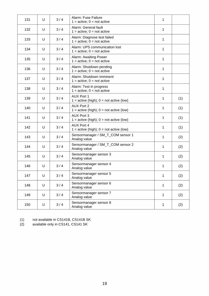
19
131 U 3 / 4 Alarm: Fuse Failure 1 = active; 0 = not active
1
132 U 3 / 4 Alarm: General fault 1 = active; 0 = not active
1
133 U 3 / 4 Alarm: Diagnose test failed 1 = active; 0 = not active
1
134 U 3 / 4 Alarm: UPS communication lost 1 = active; 0 = not active
1
135 U 3 / 4 Alarm: Awaiting Power 1 = active; 0 = not active
1
136 U 3 / 4 Alarm: Shutdown pending 1 = active; 0 = not active
1
137 U 3 / 4 Alarm: Shutdown imminent 1 = active; 0 = not active
1
138 U 3 / 4 Alarm: Test in progress 1 = active; 0 = not active
1
139 U 3 / 4 AUX Port 1 1 = active (high); 0 = not active (low)
1 (1)
140 U 3 / 4 AUX Port 2 1 = active (high); 0 = not active (low)
1 (1)
141 U 3 / 4 AUX Port 3 1 = active (high); 0 = not active (low)
1 (1)
142 U 3 / 4 AUX Port 4 1 = active (high); 0 = not active (low)
1 (1)
143 U 3 / 4 Sensormanager / SM_T_COM sensor 1 Analog value
1 (2)
144 U 3 / 4 Sensormanager / SM_T_COM sensor 2 Analog value
1 (2)
145 U 3 / 4 Sensormanager sensor 3 Analog value
1 (2)
146 U 3 / 4 Sensormanager sensor 4 Analog value
1 (2)
147 U 3 / 4 Sensormanager sensor 5 Analog value
1 (2)
148 U 3 / 4 Sensormanager sensor 6 Analog value
1 (2)
149 U 3 / 4 Sensormanager sensor 7 Analog value
1 (2)
150 U 3 / 4 Sensormanager sensor 8 Analog value
1 (2)
(1) not available in CS141B, CS141B SK
(2) available only in CS141, CS141 SK

20
3.8. Keor MOD
Address Type Function Description Length Notes
97 U 3 / 4 Output Voltage L1 [V] 1
98 U 3 / 4 Output Voltage L2 [V] 1
99 U 3 / 4 Output Voltage L3 [V] 1
100 U 3 / 4 Output Power L1 [%] 1
101 U 3 / 4 Output Power L2 [%] 1
102 U 3 / 4 Output Power L3 [%] 1
103 U 3 / 4 Battery Charge Level [%] 1
104 U 3 / 4 Input Voltage L1 [V] 1
105 U 3 / 4 Input Voltage L2 [V] 1
106 S 3 / 4 Input Voltage L3 [V] 1
107 S 3 / 4 Temperature [C°] 1
108 S 3 / 4 Autonomy Time [minutes] 1
109 U 3 / 4 UPS Status (ASCII HEX) Please check “Status Bytes table“ below
1
110 S 3 / 4 Battery Voltage [V] 1
111 U 3 / 4 Input Frequency L1 [Hz] 1
112 U 3 / 4 Input Frequency L2 [Hz] 1
113 U 3 / 4 Input Frequency L3 [Hz] 1
114 U 3 / 4 Powerfail Counter 1
116 U 3 / 4 Alarm: On Battery 1 = active; 0 = not active
1
117 U 3 / 4 Alarm: Battery Low 1 = active; 0 = not active
1
119 U 3 / 4 Alarm: Over Temperature 1 = active; 0 = not active
1
122 U 3 / 4 Alarm: Output Overload 1 = active; 0 = not active
1
123 U 3 / 4 Alarm: On Bypass 1 = active; 0 = not active
1
132 U 3 / 4 Alarm: General Fault 1 = active; 0 = not active
1
134 U 3 / 4 Alarm: UPS communication lost 1 = active; 0 = not active
1
138 U 3 / 4 Alarm: Test in progress 1 = active; 0 = not active
1
139 U 3 / 4 AUX Port 1 1 = active (high); 0 = not active (low)
1 (1)
140 U 3 / 4 AUX Port 2 1 = active (high); 0 = not active (low)
1 (1)
141 U 3 / 4 AUX Port 3 1 = active (high); 0 = not active (low)
1 (1)
142 U 3 / 4 AUX Port 4 1 = active (high); 0 = not active (low)
1 (1)
143 U 3 / 4 Sensormanager / SM_T_COM sensor 1 Analog value
1 (2)
144 U 3 / 4 Sensormanager / SM_T_COM sensor 2 Analog value
1 (2)

21
145 U 3 / 4 Sensormanager sensor 3 Analog value
1 (2)
146 U 3 / 4 Sensormanager sensor 4 Analog value
1 (2)
147 U 3 / 4 Sensormanager sensor 5 Analog value
1 (2)
148 U 3 / 4 Sensormanager sensor 6 Analog value
1 (2)
149 U 3 / 4 Sensormanager sensor 7 Analog value
1 (2)
150 U 3 / 4 Sensormanager sensor 8 Analog value
1 (2)
(1) not available in CS141B, CS141B SK
(2) available only in CS141, CS141 SK

22
3.9. Status Bytes table ( see registry 109 of all previous tables )
UPS Status Hex Value Dec Value Description
UPS_SB_BYPASS_MODE 0x0001 1 UPS is in bypass
UPS_SB_SHUTDOWN 0x0002 2 Shutdown UPS
UPS_SB_OUTPUT_ACT 0x0004 4 Inverter on = UPS OK
UPS_SB_BACKUP_MODE 0x0008 8 UPS is working in battery mode
UPS_SB_BATTERY_LOW 0x0010 16 Battery Low signal
UPS_SB_OVER_TEMP 0x0020 32 Over temperature
UPS_SB_TEST_ACT 0x0040 64 Test in progress
UPS_SB_INPUT_HIGH 0x0080 128 Input voltage too high
UPS_SB_OUTPUT_HIGH 0x0100 256 Overload
UPS_SB_INVERTER_FAILURE 0x0200 512 Inverter error
UPS_SB_BATTERY_BAD 0x0400 1024 Battery error
UPS_SB_ECO_MODE 0x0800 2048 ECO mode
UPS_SB_COMM_LOST 0x4000 16384 For snmp
Examples (decimal):
• STATUS= “4” means UPS_SB_OUTPUT_ACT (4) + no other alarms = UPS OK
• STATUS= “5” means UPS_SB_OUTPUT_ACT (4) + UPS_SB_BYPASS_MODE (1) are active ! = UPS on Bypass!
• STATUS= “12” means UPS_SB_OUTPUT_ACT (4) + UPS_SB_BACKUP_MODE (8) are active ! = UPS Powerfail!
• STATUS= “22” means UPS_SB_OUTPUT_ACT (4) + UPS_SB_BACKUP_MODE (8) + UPS_SB_BATTERY_LOW (10) are active ! = UPS Powerfail and Battery low!
• STATUS= “68” means UPS_SB_OUTPUT_ACT (4) + UPS_SB_TEST_ACT (64) are active ! = UPS battery test is running

23
4. Appendix
4.1. RS485 Connector for CS141M and CS141M SK
Phoenix 1952267 connector:
Pin 1: -> GND Pin 2: -> RS485 (+) Pin 3: -> RS485 (-)
4.2. Bus termination
It is necessary to set the last bus device on the RS485 bus jumper for the bus termination (120 ohm). Please remove the 4 screws at the buttom of the adapter in order to open the box. You will find the jumper near the Modbus connector (see below). Default is OFF (CS141 is NOT last device). To terminate the RS485 bus at your CS141, please close the Jumper.