Modbus on CO2 Engine and eSENSE - senseair.jp
20
Document TDE2336 Rev 7 Page 1 (20) Modbus on CO 2 Engine and eSENSE Table of contents: 1. General .......................................................................................................... 2 2. Byte transmission. .............................................................................................. 3 3. Modbus registers on sensor. .................................................................................. 4 4. Serial line frame and addressing. ............................................................................ 8 5. Bus timing. ....................................................................................................... 8 6. References......................................................................................................14 7. Appendix A: Application examples ..........................................................................15
Transcript of Modbus on CO2 Engine and eSENSE - senseair.jp

Document TDE2336
Rev 7
Page 1 (20)
Modbus on CO2 Engine and eSENSE
Table of contents:
1. General .......................................................................................................... 2 2. Byte transmission. .............................................................................................. 3 3. Modbus registers on sensor. .................................................................................. 4 4. Serial line frame and addressing. ............................................................................ 8 5. Bus timing. ....................................................................................................... 8 6. References......................................................................................................14 7. Appendix A: Application examples ..........................................................................15
Document TDE2336
Rev 7
Page 2 (20)
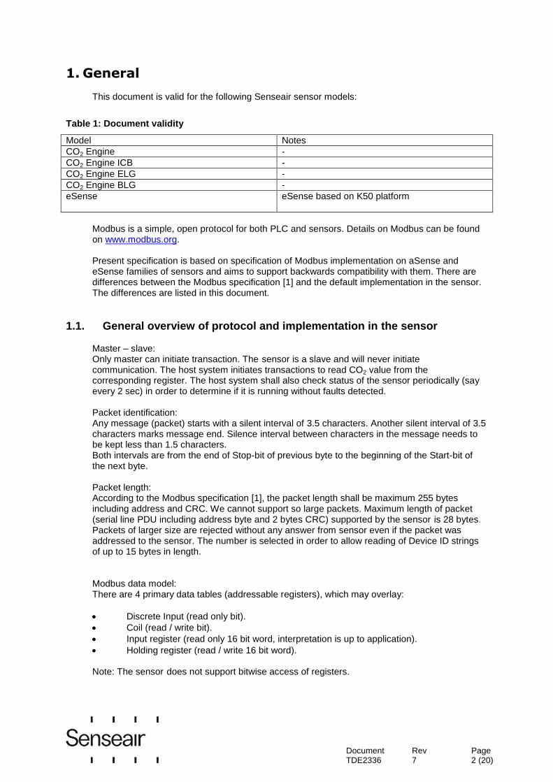
1. General
This document is valid for the following Senseair sensor models:
Table 1: Document validity
Model Notes
CO2 Engine -
CO2 Engine ICB -
CO2 Engine ELG -
CO2 Engine BLG -
eSense eSense based on K50 platform
Modbus is a simple, open protocol for both PLC and sensors. Details on Modbus can be found on www.modbus.org. Present specification is based on specification of Modbus implementation on aSense and eSense families of sensors and aims to support backwards compatibility with them. There are differences between the Modbus specification [1] and the default implementation in the sensor. The differences are listed in this document.
1.1. General overview of protocol and implementation in the sensor
Master – slave: Only master can initiate transaction. The sensor is a slave and will never initiate communication. The host system initiates transactions to read CO2 value from the corresponding register. The host system shall also check status of the sensor periodically (say every 2 sec) in order to determine if it is running without faults detected. Packet identification: Any message (packet) starts with a silent interval of 3.5 characters. Another silent interval of 3.5 characters marks message end. Silence interval between characters in the message needs to be kept less than 1.5 characters. Both intervals are from the end of Stop-bit of previous byte to the beginning of the Start-bit of the next byte. Packet length: According to the Modbus specification [1], the packet length shall be maximum 255 bytes including address and CRC. We cannot support so large packets. Maximum length of packet (serial line PDU including address byte and 2 bytes CRC) supported by the sensor is 28 bytes. Packets of larger size are rejected without any answer from sensor even if the packet was addressed to the sensor. The number is selected in order to allow reading of Device ID strings of up to 15 bytes in length. Modbus data model: There are 4 primary data tables (addressable registers), which may overlay:
Discrete Input (read only bit).
Coil (read / write bit).
Input register (read only 16 bit word, interpretation is up to application).
Holding register (read / write 16 bit word). Note: The sensor does not support bitwise access of registers.
Document TDE2336
Rev 7
Page 3 (20)
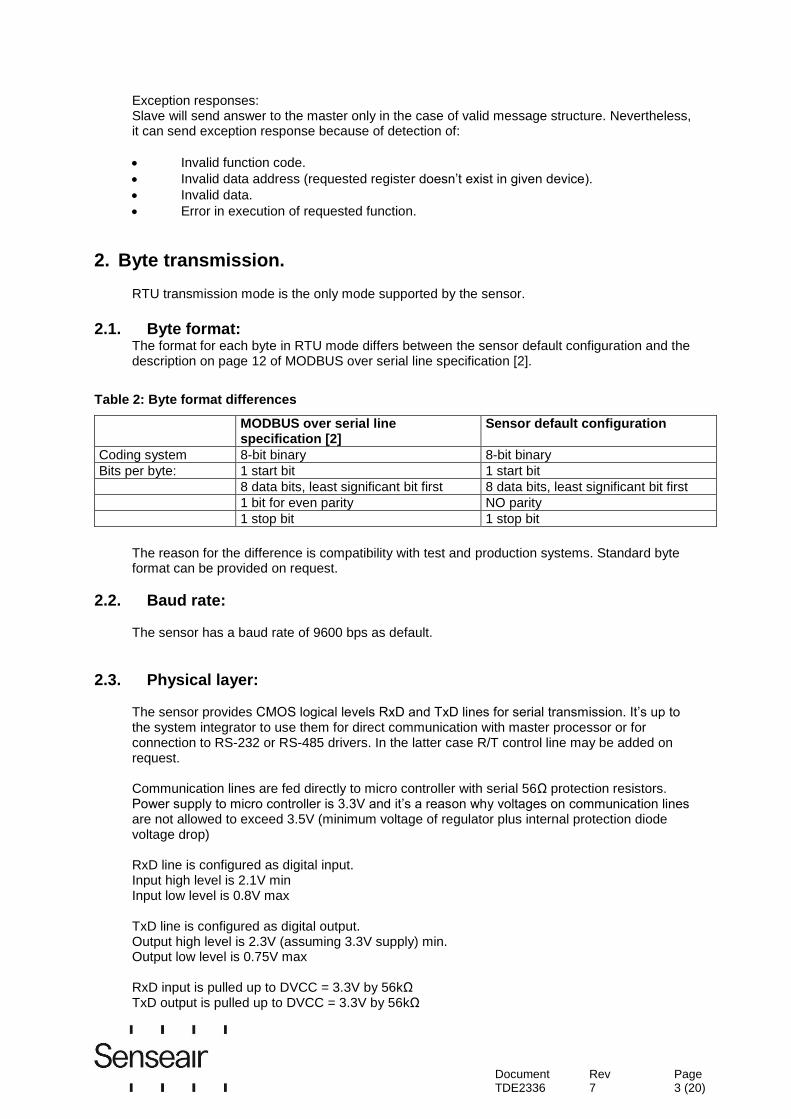
Exception responses: Slave will send answer to the master only in the case of valid message structure. Nevertheless, it can send exception response because of detection of:
Invalid function code.
Invalid data address (requested register doesn’t exist in given device).
Invalid data.
Error in execution of requested function.
2. Byte transmission.
RTU transmission mode is the only mode supported by the sensor.
2.1. Byte format:
The format for each byte in RTU mode differs between the sensor default configuration and the description on page 12 of MODBUS over serial line specification [2].
Table 2: Byte format differences
MODBUS over serial line specification [2]
Sensor default configuration
Coding system 8-bit binary 8-bit binary
Bits per byte: 1 start bit 1 start bit
8 data bits, least significant bit first 8 data bits, least significant bit first
1 bit for even parity NO parity
1 stop bit 1 stop bit
The reason for the difference is compatibility with test and production systems. Standard byte format can be provided on request.
2.2. Baud rate: The sensor has a baud rate of 9600 bps as default.
2.3. Physical layer:
The sensor provides CMOS logical levels RxD and TxD lines for serial transmission. It’s up to the system integrator to use them for direct communication with master processor or for connection to RS-232 or RS-485 drivers. In the latter case R/T control line may be added on request. Communication lines are fed directly to micro controller with serial 56Ω protection resistors. Power supply to micro controller is 3.3V and it’s a reason why voltages on communication lines are not allowed to exceed 3.5V (minimum voltage of regulator plus internal protection diode voltage drop) RxD line is configured as digital input. Input high level is 2.1V min Input low level is 0.8V max TxD line is configured as digital output. Output high level is 2.3V (assuming 3.3V supply) min. Output low level is 0.75V max RxD input is pulled up to DVCC = 3.3V by 56kΩ TxD output is pulled up to DVCC = 3.3V by 56kΩ
Document TDE2336
Rev 7
Page 4 (20)
3. Modbus registers on sensor.
The Modbus registers are mapped in memory, both RAM and EEPROM of the sensor. Mapping is interpreted by sensor firmware at command reception.
Presently, the following restrictive decisions are made: 1. Read only and read / write registers are not allowed to overlay. 2. Bit addressable items (i.e. Coils and Discrete inputs) will not be implemented. 3. Only write single register functional codes are implemented. Multiple write functional codes are not planned for implementation. 4. The total number of registers should be limited. Present decision is to limit number of input registers to 32 and number of holding registers to 32. Note: the limited buffer space of the sensor puts a limit on how many registers that can be read in one command, currently 6 registers. 5. Larger amount of data should be transferred as file. It is not implemented at the current stage of development.
Maps of registers (All registers are 16 bit word) are summarized in Table 1 and Table 2. Associated number is Modbus register number: Register address is calculated as (register number -1)
Table 3 : Input Registers
IR# # Name
IR1 0 MeterStatus DI 16
DI 15
DI 14
DI 13
DI 12
DI 11
DI 10
DI 9
DI 8
DI 7
DI 6
DI 5
DI 4
DI 3
DI 2
DI 1
DI 1 - Fatal error DI 2 - Offset regulation error DI 3 - Algorithm Error DI 4 - Output Error DI 5 - Self diagnostics error DI 6 - Out Of Range DI 7 - Memory error DI 8 - Reserved DI 9 - Reserved DI 10 - Reserved DI 11 - Reserved DI 12 - Reserved DI 13 - Reserved DI 14 - Reserved DI 15 - Reserved DI 16 - Reserved
IR2 1 AlarmStatus DI 16
DI 15
DI 14
DI 13
DI 12
DI 11
DI 10
DI 9
DI 8
DI 7
DI 6
DI 5
DI 4
DI 3
DI 2
DI 1
DI 17 - DI 18 - DI 19 - DI 20 - DI 21 - DI 22 - DI 23 - DI 24 - DI 25 - DI 26 - DI 27 - DI 28 -
Document TDE2336
Rev 7
Page 5 (20)
DI 29 - DI 30 - DI 31 - DI 32 -
IR3 2 Output Status
DI 16
DI 15
DI 14
DI 13
DI 12
DI 11
DI 10
DI 9
DI 8
DI 7
DI 6
DI 5
DI 4
DI 3
DI 2
DI 1
DI 33 - DI 34 - DI 35 - DI 36 - DI 37 - DI 38 - DI 39 - DI 40 - DI 41 - DI 42 - DI 43 - DI 44 - DI 45 - DI 46 - DI 47 - DI 48 -
IR4 3 Space CO2 Space CO2
IR5 4 Reserved for Space Temp, returns "illegal data address" exception
IR6 5 Reserved, returns "illegal data address" exception
IR7 6 Reserved, returns "illegal data address" exception
IR8 7 Reserved, returns "illegal data address" exception
IR9 8 Reserved, returns "illegal data address" exception
IR10 9 Reserved, returns "illegal data address" exception
IR11 10 Reserved, returns "illegal data address" exception
IR12 11 Reserved, returns "illegal data address" exception
IR13 12 Reserved, returns "illegal data address" exception
IR14 13 Reserved, returns "illegal data address" exception
IR15 14 Reserved, returns "illegal data address" exception
IR16 15 Reserved, returns "illegal data address" exception
IR17 16 Reserved, returns "illegal data address" exception
IR18 17 Reserved, returns "illegal data address" exception
IR19 18 Reserved, returns "illegal data address" exception
IR20 19 Reserved, returns "illegal data address" exception
IR21 20 Reserved, returns "illegal data address" exception
IR22 21 Output 1 * Output 1
IR23 22 Output 2 * Output 2
Document TDE2336
Rev 7
Page 6 (20)
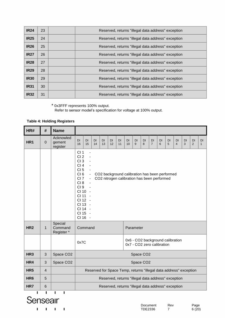
IR24 23 Reserved, returns "illegal data address" exception
IR25 24 Reserved, returns "illegal data address" exception
IR26 25 Reserved, returns "illegal data address" exception
IR27 26 Reserved, returns "illegal data address" exception
IR28 27 Reserved, returns "illegal data address" exception
IR29 28 Reserved, returns "illegal data address" exception
IR30 29 Reserved, returns "illegal data address" exception
IR31 30 Reserved, returns "illegal data address" exception
IR32 31 Reserved, returns "illegal data address" exception
* 0x3FFF represents 100% output.
Refer to sensor model’s specification for voltage at 100% output.
Table 4: Holding Registers
HR# # Name
HR1 0 Acknowledgement register
DI 16
DI 15
DI 14
DI 13
DI 12
DI 11
DI 10
DI 9
DI 8
DI 7
DI 6
DI 5
DI 4
DI 3
DI 2
DI 1
CI 1 - CI 2 - CI 3 - CI 4 - CI 5 - CI 6 - CO2 background calibration has been performed CI 7 - CO2 nitrogen calibration has been performed CI 8 - CI 9 - CI 10 - CI 11 - CI 12 - CI 13 - CI 14 - CI 15 - CI 16 -
HR2 1 Special Command Register *
Command Parameter
0x7C 0x6 - CO2 background calibration 0x7 - CO2 zero calibration
HR3 3 Space CO2 Space CO2
HR4 3 Space CO2 Space CO2
HR5 4 Reserved for Space Temp, returns "illegal data address" exception
HR6 5 Reserved, returns "illegal data address" exception
HR7 6 Reserved, returns "illegal data address" exception

Document TDE2336
Rev 7
Page 7 (20)
HR8 7 Reserved, returns "illegal data address" exception
HR9 8 Reserved, returns "illegal data address" exception
HR10 9 Reserved, returns "illegal data address" exception
HR11 10 Reserved, returns "illegal data address" exception
HR12 11 Reserved, returns "illegal data address" exception
HR13 12 Reserved, returns "illegal data address" exception
HR14 13 Reserved, returns "illegal data address" exception
HR15 14 Reserved, returns "illegal data address" exception
HR16 15 Reserved, returns "illegal data address" exception
HR17 16 Reserved, returns "illegal data address" exception
HR18 17 Reserved, returns "illegal data address" exception
HR19 18 Reserved, returns "illegal data address" exception
HR20 19 Reserved, returns "illegal data address" exception
HR21 20 Reserved, returns "illegal data address" exception
HR22 21 Reserved, returns "illegal data address" exception
HR23 22 Reserved, returns "illegal data address" exception
HR24 23 Reserved, returns "illegal data address" exception
HR25 24 Reserved, returns "illegal data address" exception
HR26 25 Reserved, returns "illegal data address" exception
HR27 26 Reserved, returns "illegal data address" exception
HR28 27 Reserved, returns "illegal data address" exception
HR29 28 Reserved, returns "illegal data address" exception
HR30 29 Reserved, returns "illegal data address" exception
HR31 30 Reserved, returns "illegal data address" exception
HR32 31 ABC period ABC period in hours
* Special Command Register is write-only.
Document TDE2336
Rev 7
Page 8 (20)
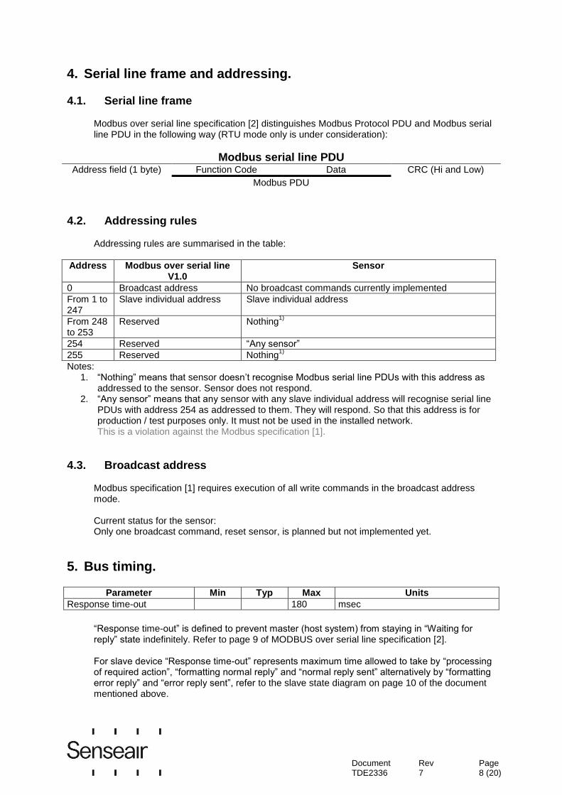
4. Serial line frame and addressing. 4.1. Serial line frame
Modbus over serial line specification [2] distinguishes Modbus Protocol PDU and Modbus serial line PDU in the following way (RTU mode only is under consideration):
Modbus serial line PDU Address field (1 byte) Function Code Data CRC (Hi and Low)
Modbus PDU
4.2. Addressing rules
Addressing rules are summarised in the table:
Address Modbus over serial line V1.0
Sensor
0 Broadcast address No broadcast commands currently implemented
From 1 to 247
Slave individual address Slave individual address
From 248 to 253
Reserved Nothing1)
254 Reserved “Any sensor”
255 Reserved Nothing1)
Notes: 1. “Nothing” means that sensor doesn’t recognise Modbus serial line PDUs with this address as
addressed to the sensor. Sensor does not respond. 2. “Any sensor” means that any sensor with any slave individual address will recognise serial line
PDUs with address 254 as addressed to them. They will respond. So that this address is for production / test purposes only. It must not be used in the installed network. This is a violation against the Modbus specification [1].
4.3. Broadcast address
Modbus specification [1] requires execution of all write commands in the broadcast address mode. Current status for the sensor: Only one broadcast command, reset sensor, is planned but not implemented yet.
5. Bus timing.
Parameter Min Typ Max Units
Response time-out 180 msec
“Response time-out” is defined to prevent master (host system) from staying in “Waiting for reply” state indefinitely. Refer to page 9 of MODBUS over serial line specification [2]. For slave device “Response time-out” represents maximum time allowed to take by “processing of required action”, “formatting normal reply” and “normal reply sent” alternatively by “formatting error reply” and “error reply sent”, refer to the slave state diagram on page 10 of the document mentioned above.

Document TDE2336
Rev 7
Page 9 (20)
5.1. 01 (0x01) Read Coils (one bit read / write registers).
Not implemented.
5.2. 02 (0x02) Read Discrete Inputs (one bit read only registers).
Not implemented.
5.3. 03 (0x03) Read Holding Registers (16 bits read / write registers).
Refer to Modbus specification [1]. Quantity of Registers is limited to 8.
Address of Modbus Holding Registers for 1-command reading is limited in range 0x0000..0x001F. Request PDU
Function code 1 byte 0x03
Starting Address Hi 1 byte Address Hi
Starting Address Lo 1 byte Address Lo
Quantity of Registers Hi 1 byte Quantity Hi
Quantity of Registers Lo 1 byte Quantity Lo
Response PDU
Function code 1 byte 0x03
Byte Count 1 byte 2 x N*
Register Value N* x 2 bytes
* N = Quantity of Registers If Address>0x001F or (Address + Quantity)>0x0020: Exception Response PDU,
Function code 1 byte 0x83
Exception code = Illegal Data Address 1 byte 0x02
If Quantity=0 or Quantity>8: Exception Response PDU,
Function code 1 byte 0x83
Exception code = Illegal Data Value 1 byte 0x03
Document TDE2336
Rev 7
Page 10 (20)
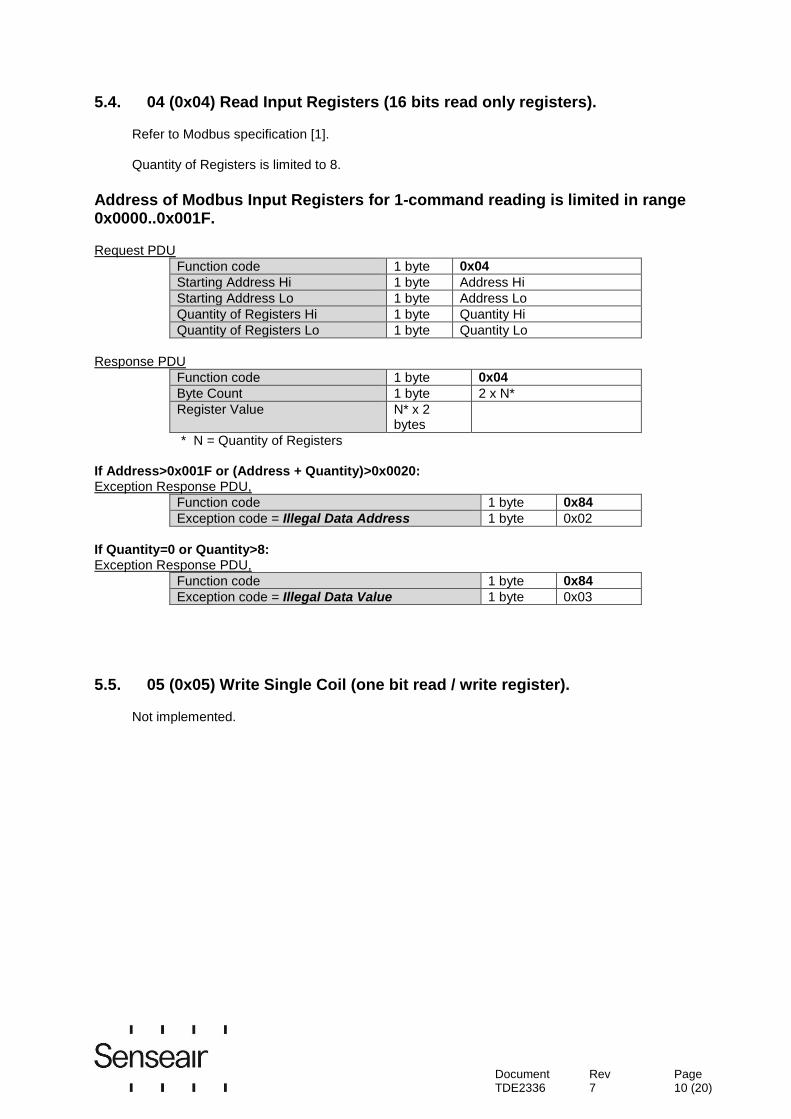
5.4. 04 (0x04) Read Input Registers (16 bits read only registers).
Refer to Modbus specification [1]. Quantity of Registers is limited to 8.
Address of Modbus Input Registers for 1-command reading is limited in range 0x0000..0x001F. Request PDU
Function code 1 byte 0x04
Starting Address Hi 1 byte Address Hi
Starting Address Lo 1 byte Address Lo
Quantity of Registers Hi 1 byte Quantity Hi
Quantity of Registers Lo 1 byte Quantity Lo
Response PDU
Function code 1 byte 0x04
Byte Count 1 byte 2 x N*
Register Value N* x 2 bytes
* N = Quantity of Registers If Address>0x001F or (Address + Quantity)>0x0020: Exception Response PDU,
Function code 1 byte 0x84
Exception code = Illegal Data Address 1 byte 0x02
If Quantity=0 or Quantity>8: Exception Response PDU,
Function code 1 byte 0x84
Exception code = Illegal Data Value 1 byte 0x03
5.5. 05 (0x05) Write Single Coil (one bit read / write register).
Not implemented.

Document TDE2336
Rev 7
Page 11 (20)
5.6. 06 (0x06) Write Single Register (16 bits read / write register).
Refer to Modbus specification [1].
Address of Modbus Holding Registers for 1-command reading/writing is limited in range 0x0000..0x001F. Request PDU
Function code 1 byte 0x06
Starting Address Hi 1 byte Address Hi
Starting Address Lo 1 byte Address Lo
Register Value Hi 1 byte Value Hi
Register Value Lo 1 byte Value Lo
Response PDU (is an echo of the Request)
Function code 1 byte 0x06
Starting Address Hi 1 byte Address Hi
Starting Address Lo 1 byte Address Lo
Register Value Hi 1 byte Value Hi
Register Value Lo 1 byte Value Lo
If Address>0x001F: Exception Response PDU,
Function code 1 byte 0x86
Exception code = Illegal Data Address 1 byte 0x02
5.7. 15 (0x0F) Write Multiple Coils (one bit read / write registers).
Not implemented.
5.8. 16 (0x10) Write Multiple Registers (16 bits read / write register). Not implemented.
5.9. 20 (0x14) Read File record. Not implemented.
5.10. 21 (0x15) Write File record. Not implemented.
5.11. 22 (0x16) Mask Write Register (16 bits read / write register). Not implemented.
5.12. 23 (0x17) Read / Write Multiple Registers (16 bits read / write register).
Not implemented.
Document TDE2336
Rev 7
Page 12 (20)
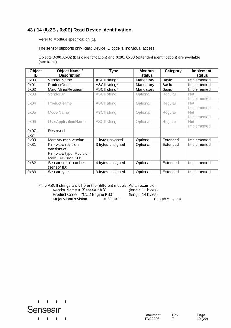
43 / 14 (0x2B / 0x0E) Read Device Identification.
Refer to Modbus specification [1].
The sensor supports only Read Device ID code 4, individual access. Objects 0x00..0x02 (basic identification) and 0x80..0x83 (extended identification) are available (see table)
Object ID
Object Name / Description
Type Modbus status
Category
Implement. status
0x00 Vendor Name ASCII string* Mandatory Basic Implemented
0x01 ProductCode ASCII string* Mandatory Basic Implemented
0x02 MajorMinorRevision ASCII string* Mandatory Basic Implemented
0x03 VendorUrl ASCII string Optional Regular Not Implemented
0x04 ProductName ASCII string Optional Regular Not Implemented
0x05 ModelName ASCII string Optional Regular Not Implemented
0x06 UserApplicationName ASCII string Optional Regular Not Implemented
0x07.. 0x7F
Reserved
0x80 Memory map version 1 byte unsigned Optional Extended Implemented
0x81 Firmware revision, consists of: Firmware type, Revision Main, Revision Sub
3 bytes unsigned
Optional Extended Implemented
0x82 Sensor serial number (sensor ID)
4 bytes unsigned Optional Extended Implemented
0x83 Sensor type 3 bytes unsigned Optional Extended Implemented
*The ASCII strings are different for different models. As an example: Vendor Name = “SenseAir AB” (length 11 bytes) Product Code = “CO2 Engine K30” (length 14 bytes) MajorMinorRevision = “V1.00” (length 5 bytes)

Document TDE2336
Rev 7
Page 13 (20)
Example: Read objects of category “Basic”. Request PDU, Object ID 0x00 to 0x02
Function code 1 byte 0x2B
MEI Type 1 byte 0x0E
Read Device ID code 1 byte 0x04 (individual access only)
Object ID 1 byte 0x00..0x02
Response PDU, Object ID 0x00 to 0x02
Function code 1 byte 0x2B
MEI Type 1 byte 0x0E
Read Device ID code 1 byte 0x04, same as in request
Conformity level 1 byte 0x81, basic identification for individual or stream access
More Follows 1 byte 0x00
Next Object ID 1 byte 0x00
Number of objects 1 byte 0x01
Object ID 1 byte 0x00..0x02
Object length 1 byte 0x0B or 0x0E or 0x05 (see definition of ASCII strings)
Object value n byte Object Data
Example: Read objects of category “Extended”. Request PDU, Object ID 0x80 to 0x83
Function code 1 byte 0x2B
MEI Type 1 byte 0x0E
Read Device ID code 1 byte 0x04 (individual access only)
Object ID 1 byte 0x80..0x83
Response PDU, Object ID 0x80 to 0x83
Function code 1 byte 0x2B
MEI Type 1 byte 0x0E
Read Device ID code 1 byte 0x04, same as in request
Conformity level 1 byte 0x83 : extended identification for individual or stream access
More Follows 1 byte 0x00
Next Object ID 1 byte 0x00
Number of objects 1 byte 0x01
Object ID 1 byte 0x80..0x83
Object length 1 byte 0x01 or 0x03 or 0x04
Object value 1 or 3 or 4 byte
Object Data
Document TDE2336
Rev 7
Page 14 (20)
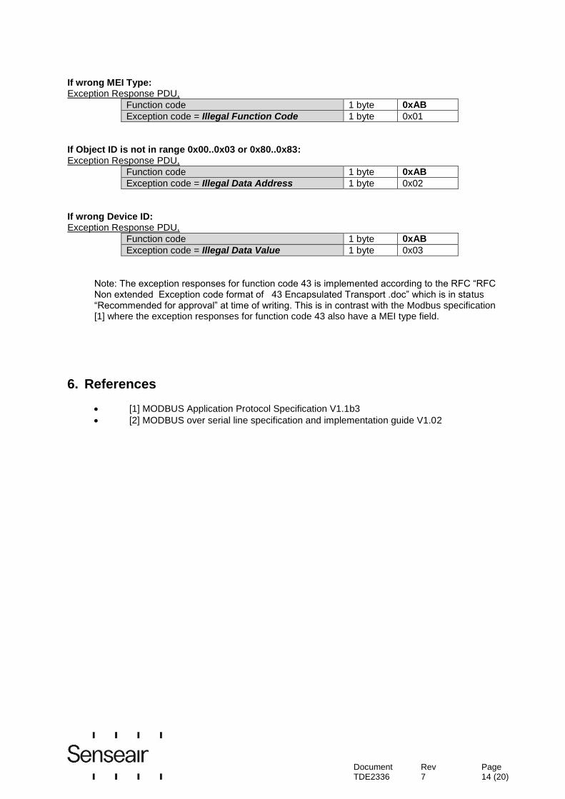
If wrong MEI Type: Exception Response PDU,
Function code 1 byte 0xAB
Exception code = Illegal Function Code 1 byte 0x01
If Object ID is not in range 0x00..0x03 or 0x80..0x83: Exception Response PDU,
Function code 1 byte 0xAB
Exception code = Illegal Data Address 1 byte 0x02
If wrong Device ID: Exception Response PDU,
Function code 1 byte 0xAB
Exception code = Illegal Data Value 1 byte 0x03
Note: The exception responses for function code 43 is implemented according to the RFC “RFC Non extended Exception code format of 43 Encapsulated Transport .doc” which is in status “Recommended for approval” at time of writing. This is in contrast with the Modbus specification [1] where the exception responses for function code 43 also have a MEI type field.
6. References
[1] MODBUS Application Protocol Specification V1.1b3
[2] MODBUS over serial line specification and implementation guide V1.02

Document TDE2336
Rev 7
Page 15 (20)
7. Appendix A: Application examples
Prerequisites for the application examples:
1. A single slave (sensor) is assumed (address “any sensor” is used). 2. Values in <..> are hexadecimal.
CO2 read sequence:
The sensor is addressed as “Any address” (0xFE). We read CO2 value from IR4 using “Read input registers” (function code 04). Hence, Starting address will be 0x0003 (register number-1) and Quantity of registers 0x0001. CRC calculated to 0xC5D5 is sent with low byte first. We assume in this example that by sensor measured CO2 value is 400ppm*. Sensor replies with CO2 reading 400ppm (400 ppm = 0x190 hexadecimal).
Master Transmit: <FE> <04> <00> <03> <00> <01> <D5> <C5> Slave Reply: <FE> <04> <02> <01> <90> <AC> <D8>
* Note that some models, e.g. CO2 Engine ICB has a different scale factor on the ppm reading.
The reading on these models is divided by 10 (i.e. when ambient CO2 level is 400ppm the sensor will transmit the number 40). In this example the reply from one of these models would be 40 (= 0x28 hexadecimal).
Sensor status read sequence:
The sensor is addressed as “Any address” (0xFE). We read status from IR1 using “Read input registers” (function code 04). Hence, Starting address will be 0x0000 (register number-1) and Quantity of registers 0x0001. CRC calculated to 0xC525 is sent with low byte first. Sensor replies with status 0. Master Transmit: <FE> <04> <00> <00> <00> <01> <25> <C5> Slave Reply: <FE> <04> <02> <00> <00> <AD> <24>
Document TDE2336
Rev 7
Page 16 (20)
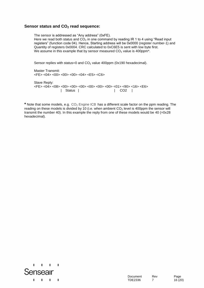
Sensor status and CO2 read sequence:
The sensor is addressed as “Any address” (0xFE). Here we read both status and CO2 in one command by reading IR 1 to 4 using “Read input registers” (function code 04). Hence, Starting address will be 0x0000 (register number-1) and Quantity of registers 0x0004. CRC calculated to 0xC6E5 is sent with low byte first. We assume in this example that by sensor measured CO2 value is 400ppm*. Sensor replies with status=0 and CO2 value 400ppm (0x190 hexadecimal). Master Transmit: <FE> <04> <00> <00> <00> <04> <E5> <C6> Slave Reply: <FE> <04> <08> <00> <00> <00> <00> <00> <00> <01> <90> <16> <E6> | Status | | CO2 |
* Note that some models, e.g. CO2 Engine ICB has a different scale factor on the ppm reading. The
reading on these models is divided by 10 (i.e. when ambient CO2 level is 400ppm the sensor will transmit the number 40). In this example the reply from one of these models would be 40 (=0x28 hexadecimal).
Document TDE2336
Rev 7
Page 17 (20)
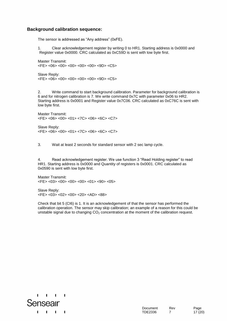
Background calibration sequence:
The sensor is addressed as “Any address” (0xFE). 1. Clear acknowledgement register by writing 0 to HR1. Starting address is 0x0000 and Register value 0x0000. CRC calculated as 0xC59D is sent with low byte first.
Master Transmit: <FE> <06> <00> <00> <00> <00> <9D> <C5> Slave Reply: <FE> <06> <00> <00> <00> <00> <9D> <C5> 2. Write command to start background calibration. Parameter for background calibration is 6 and for nitrogen calibration is 7. We write command 0x7C with parameter 0x06 to HR2. Starting address is 0x0001 and Register value 0x7C06. CRC calculated as 0xC76C is sent with low byte first. Master Transmit: <FE> <06> <00> <01> <7C> <06> <6C> <C7> Slave Reply: <FE> <06> <00> <01> <7C> <06> <6C> <C7> 3. Wait at least 2 seconds for standard sensor with 2 sec lamp cycle.
4. Read acknowledgement register. We use function 3 “Read Holding register” to read HR1. Starting address is 0x0000 and Quantity of registers is 0x0001. CRC calculated as 0x0590 is sent with low byte first. Master Transmit: <FE> <03> <00> <00> <00> <01> <90> <05> Slave Reply: <FE> <03> <02> <00> <20> <AD> <88> Check that bit 5 (CI6) is 1. It is an acknowledgement of that the sensor has performed the calibration operation. The sensor may skip calibration; an example of a reason for this could be unstable signal due to changing CO2 concentration at the moment of the calibration request.
Document TDE2336
Rev 7
Page 18 (20)
Read Device ID, Vendor Name:
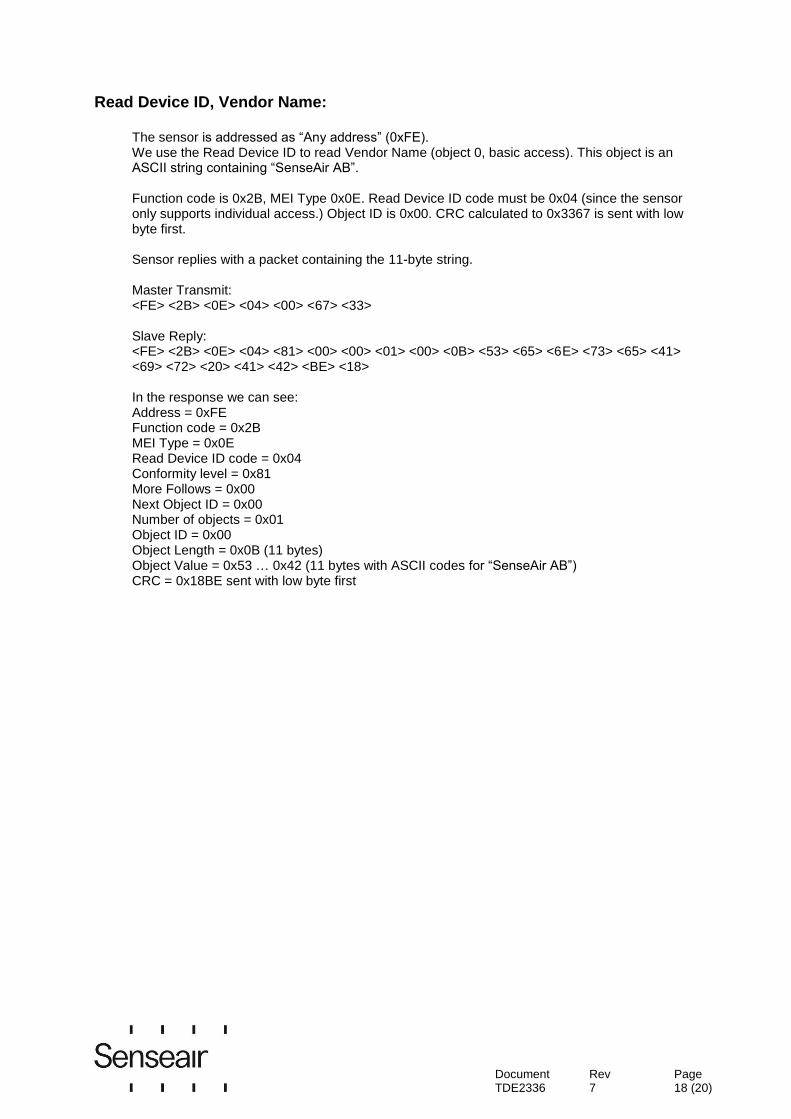
The sensor is addressed as “Any address” (0xFE). We use the Read Device ID to read Vendor Name (object 0, basic access). This object is an ASCII string containing “SenseAir AB”. Function code is 0x2B, MEI Type 0x0E. Read Device ID code must be 0x04 (since the sensor only supports individual access.) Object ID is 0x00. CRC calculated to 0x3367 is sent with low byte first. Sensor replies with a packet containing the 11-byte string.
Master Transmit: <FE> <2B> <0E> <04> <00> <67> <33> Slave Reply: <FE> <2B> <0E> <04> <81> <00> <00> <01> <00> <0B> <53> <65> <6E> <73> <65> <41> <69> <72> <20> <41> <42> <BE> <18> In the response we can see: Address = 0xFE Function code = 0x2B MEI Type = 0x0E Read Device ID code = 0x04 Conformity level = 0x81 More Follows = 0x00 Next Object ID = 0x00 Number of objects = 0x01 Object ID = 0x00 Object Length = 0x0B (11 bytes) Object Value = 0x53 … 0x42 (11 bytes with ASCII codes for “SenseAir AB”) CRC = 0x18BE sent with low byte first

Document TDE2336
Rev 7
Page 19 (20)
Read ABC parameter, ABC_PERIOD:
One of the ABC parameters, ABC_PERIOD, is available for modification as it is mapped as a holding register. This example shows how to read ABC_PERIOD by accessing HR32. The sensor is addressed as “Any address” (0xFE). Read current setting of ABC_PERIOD by reading HR32. We use function code 03 “Read Holding registers”. Starting address is 0x001f and Quantity of Registers 0x0001. CRC calculated as 0xC3A1 is sent with low byte first. Master Transmit: <FE> <03> <00> <1F> <00> <01> <A1> <C3> Slave Reply: <FE> <03> <02> <00> <B4> <AC> <27> In the slave reply we can see: Address = 0xFE Function code = 0x03 Byte count = 0x02 - We read 2 bytes (1 register of 16 bits) Register value = 0x00B4 - 0xB4 hexadecimal = 180 decimal;
180 hours / 24 equals 7,5 days. CRC = 0x27AC - CRC sent with low byte first
Disable ABC function
We can disable the ABC function by setting ABC_PERIOD to 0. The sensor is addressed as “Any address” (0xFE). We use function code 06 “Write Single Register” to write to HR32. Register address is 0x001f, register value 0x0000. CRC calculated as 0x03AC is sent with low byte first. Master transmit: <FE> <06> <00> <1F> <00> <00> <AC> <03> Slave reply: <FE> <06> <00> <1F> <00> <00> <AC> <03> We can see the reply which is an echo of the transmitted sequence.
Document TDE2336
Rev 7
Page 20 (20)
Enable ABC function
We can enable the ABC function by setting ABC_PERIOD to some value other than 0. In this example we set it to 7.5 days. The sensor is addressed as “Any address” (0xFE). We use function code 06 “Write Single Register” to write to HR32. Register address is 0x001f, register value 0x00B4 (7.5 days * 24 hours = 180; 180 in hexadecimal format is 0xB4). CRC calculated as 0x74AC is sent with low byte first. Master transmit: <FE> <06> <00 <1F> <00> <B4> <AC> <74> Slave reply: <FE> <06> <00> <1F> <00> <B4> <AC> <74> We can see the reply which is an echo of the transmitted sequence.
Senseair® AB Senseair
® North America Inc. Senseair
® Chengdu Gas Sensors Ltd.
Box 96 29030 SW Town Center Loop East The first floor of No. 8, Xingke, South Road Stationsgatan 12 Suite 202 - #169 Jiniu Hi-Tech, Industrial Park
SE- 82471 Delsbo Wilsonville, OR 97070 Post code 610036
Sweden USA Chengdu, China
Phone: +46(0)653 - 71 77 70 Phone: +1-520-349-7686 Phone: +86-028 - 875 928 85
E-mail: [email protected] E-mail: [email protected] E-mail: [email protected]
Web page: www.senseair.com Web page: www.senseair.com Web page: www.senseair.asia

![DPU2000/1500R/2000R MODBUS / MODBUS PLUS … · DPU2000/1500R/2000R Modbus/Modbus Plus Automation Guide i DPU2000/1500R/2000R MODBUS / MODBUS PLUS ... [Catalog 587XXX00-XXX0 or 587XXXX6-XXX4]](https://static.fdocuments.in/doc/165x107/5acb9eac7f8b9a73128bdc42/dpu20001500r2000r-modbus-modbus-plus-modbusmodbus-plus-automation-guide.jpg)