
Modbus Master Comm Manual GFK2220C
38
GFK-2220B 1 Modbus RTU Master Communications This document describes the operation of Modbus ® RTU Master from the user interface point of view. Use this information as a supplement to the Serial Communications User’s Manual (GFK-0582). This document contains the following information: Overview Supported Products Mode of Operation COMMREQs Time Constraints Serial Connections Standards Multidrop Connections Drivers and Receivers Cable Grounding Connector Wiring Four-Wire Two-Wire Point-to-Point COMMREQ Function Block Format COMMREQ Function Block Parameters COMMREQ Function Block Output COMMREQ Command Data Block Modbus RTU Master Status Word Format Queue Limitations for Modbus RTU Master COMMREQs Local Data Modbus RTU Master Diagnostic Status Words Modbus RTU Master Commands Initialize RTU Master Port: 65520 (FFF0) Clear RTU Master Diagnostic Status Words: 08000 (1F40) Read RTU Master Diagnostic Status Words: 08001 (1F41) Send RTU Read/Force/Preset Query: 08002 (1F42) Send RTU Diagnostic Query: 08003 (1F43) Error Codes Example Application ® Modbus is a registered trademark of Schneider Electric.
-
Upload
kotiasanjay -
Category
Documents
-
view
711 -
download
1
Transcript of Modbus Master Comm Manual GFK2220C

GFK-2220B 1
Modbus RTU Master Communications
This document describes the operation of Modbus® RTU Master from the user interface point of view. Use this information as a supplement to the Serial Communications User’s Manual (GFK-0582). This document contains the following information: � Overview � Supported Products � Mode of Operation � COMMREQs � Time Constraints
� Serial Connections � Standards � Multidrop Connections � Drivers and Receivers � Cable � Grounding � Connector Wiring � Four-Wire � Two-Wire
� Point-to-Point � COMMREQ Function Block Format � COMMREQ Function Block Parameters � COMMREQ Function Block Output � COMMREQ Command Data Block
� Modbus RTU Master Status Word Format � Queue Limitations for Modbus RTU Master COMMREQs � Local Data � Modbus RTU Master Diagnostic Status Words � Modbus RTU Master Commands � Initialize RTU Master Port: 65520 (FFF0) � Clear RTU Master Diagnostic Status Words: 08000 (1F40) � Read RTU Master Diagnostic Status Words: 08001 (1F41) � Send RTU Read/Force/Preset Query: 08002 (1F42) � Send RTU Diagnostic Query: 08003 (1F43)
� Error Codes � Example Application
® Modbus is a registered trademark of Schneider Electric.

2 Modbus RTU Master Communications - December 2003 GFK-2220B
Overview Modbus Serial Line protocol is an open standard for data communications between PLCs and related devices. The Modbus Serial Line standard provides for communication using either printable characters exclusively (Modbus ASCII), or binary data (Modbus RTU). This document describes Modbus RTU Master communications on GE Fanuc PLC CPUs.
Supported Products Modbus RTU Master communications is currently available on the Series 90-30 IC693CPU363 and VersaMax® modular CPU models IC200CPU001, IC200CPU002, IC200CPU005 and IC200CPUE05.
Mode of Operation A Modbus RTU master device (the client) sends query messages to one or more slave devices (the servers) on a serial network. Queries may contain data, requests for data or status, or commands.
Each slave on the network has a unique device address. Any query may be addressed either to a specific slave device or to a special broadcast address. Queries addressed to the broadcast address are called broadcast queries. Queries that require a response may not be addressed to the broadcast address.
A slave that receives a well-formed, non-broadcast query must send a response message to the master. The query/response transaction completes when the master receives a well-formed response.
Slaves do not respond to broadcast queries. After sending a broadcast query, the master must wait a specified time before completing the transaction and sending the next query. Some broadcast queries contain commands that require the slaves to take specified actions.
COMMREQs The application program running in the PLC CPU controls the timing and content of each query by sending a COMMREQ message. The COMMREQ must be addressed to the CPU serial port that is connected to the Modbus RTU serial network. COMMREQ data specifies the content of the query. When the query/response transaction completes, a COMMREQ status value indicates the success or failure of the transaction. See the COMMREQ Function Block Format section of this document and the sections that follow it for details.
Time Constraints The Modbus over Serial Line Specification and Implementation guide V1.01 contains several important timing requirements.
Serial Connections
Series 90 and VersaMax are trademarks of GE Fanuc Automation. 1 The current Modbus RTU specification is available online in the documents Modbus Application Protocol Specification V1.1 and Modbus over Serial Line Specification and Implementation guide V1.0 at http://www.modbus.org/. Follow the Modbus Standard Library link to find them.

GFK-2220B 3
A Modbus RTU network has one master device and one or more (up to 247) slave devices. A serial network interconnects all these devices. If there is only one slave, a point-to-point connection is used. A multidrop connection is needed for two or more slaves.
Standards Virtually all PLC serial communications ports (including all serial ports on GE Fanuc PLC CPUs) support one (or two or three in some cases) of three physical layer standards for asynchronous serial communications. The current revisions of all three may be purchased from the Telecommunications Industries Association at http://www.tiaonline.org/standards/.
EIA/TIA-232-F: Interface Between Data Terminal Equipment and Data Circuit-Terminating Equipment Employing Serial Binary Data Interchange (ANSI/TIA/EIA-232-F-1997)
This standard is commonly referred to as “RS-232” or “RS-232C” because the definitive earlier revision was titled “RS-232-C”. RS-232 ports transmit and receive data and control signals on unbalanced circuits. That is, one Signal Common (or Signal Ground) wire serves as the return path for all the data and control circuits.
RS-232 ports are suitable for point-to-point connections up to about 25 meters in length, but not for longer lines or multidrop connections. The specification recommends limiting the data rate to (in effect) 19,200 bits per second (bps) or less, but rates up 115,200 bps are frequently used with short cables (typically about 2 meters).
EIA/TIA-422-B: Electrical Characteristics of Balanced Voltage Digital Interface Circuits (ANSI/TIA/EIA-422-B-94, revised 2000)
This standard is usually called “RS-422” because the initial revision had that title. It specifies twisted-pair cabling and a balanced line driver and receiver for each circuit. RS-442 supports higher data rates and longer distances than RS-232. A 100-ohm nominal impedance is recommended for twisted pair circuits in cables, and 100-ohm terminating resistors are recommended for the receiving end of each circuit.
Some RS-422 ports support multidrop (multipoint) operation. However, this capability is not guaranteed by the standard. Use caution when attempting to use an RS-422 device on a multidrop network.
EIA/TIA-485-A: Electrical Characteristics of Generators and Receivers for Use in Balanced Digital Multipoint Systems (ANSI/TIA/EIA-485-A-98)
The original version of this standard was titled “RS-485”; it is frequently referred to by that name. This standard has effectively replaced RS-422 because it adds guaranteed multidrop (multipoint) capability. Line drivers in the data circuits are required to switch to a high-impedance state (“tristate” themselves) except when transmitting, and the control and status circuits are rarely connected through the cable in multidrop applications. Consequently, multiple data line drivers can be connected in parallel to each data circuit. The port firmware guarantees only one port at a time will attempt to transmit on each circuit.
RS-485 uses 120-ohm cable and terminating resistors. Because transmitters are not always connected to the line, terminating resistors must be used at both ends of each circuit.
Note that some RS-485 devices may require pull-up and pull-down resistors to polarize (bias) receive-data circuits to the mark state when all transmitters are in the high-impedance state. GE Fanuc RS-485 ports do not require pull-up and pull-down resistors.
4 Modbus RTU Master Communications - December 2003 GFK-2220B
Multidrop Connections
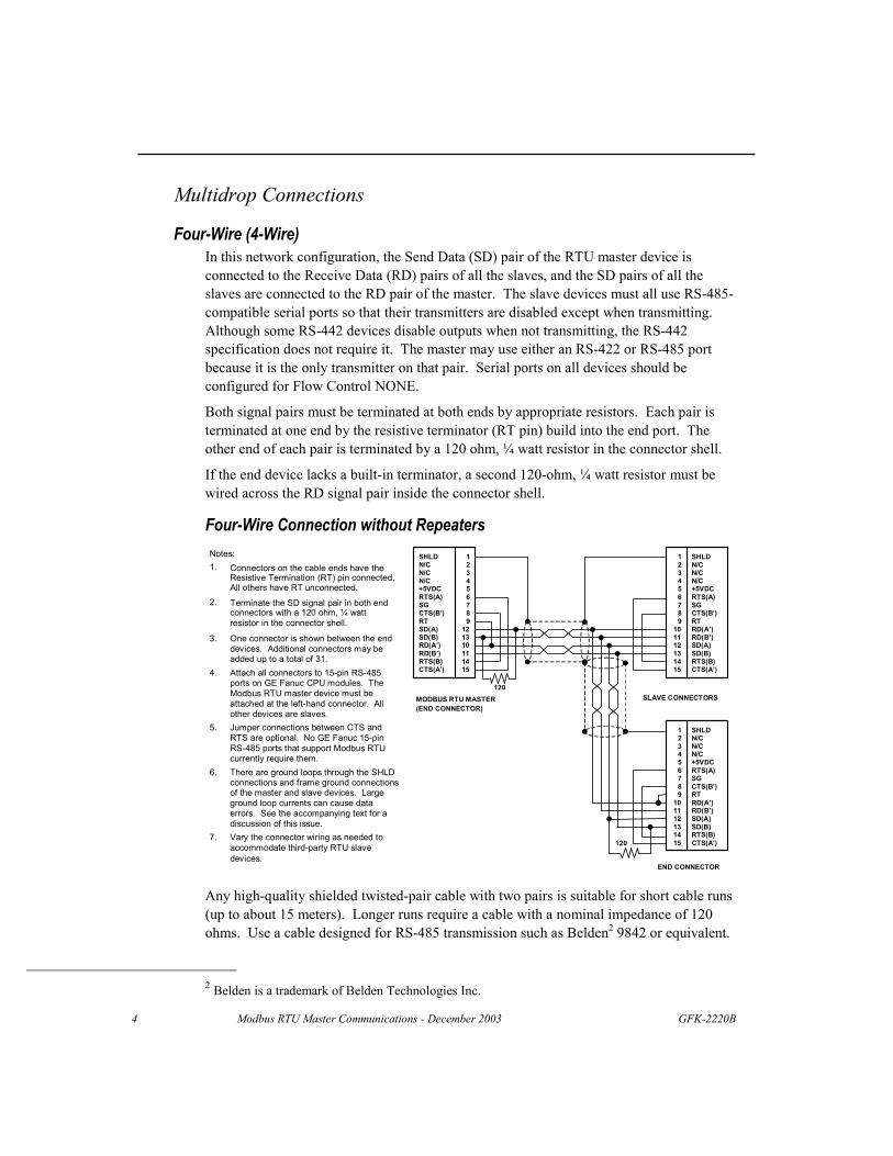
Four-Wire (4-Wire) In this network configuration, the Send Data (SD) pair of the RTU master device is connected to the Receive Data (RD) pairs of all the slaves, and the SD pairs of all the slaves are connected to the RD pair of the master. The slave devices must all use RS-485-compatible serial ports so that their transmitters are disabled except when transmitting. Although some RS-442 devices disable outputs when not transmitting, the RS-442 specification does not require it. The master may use either an RS-422 or RS-485 port because it is the only transmitter on that pair. Serial ports on all devices should be configured for Flow Control NONE.
Both signal pairs must be terminated at both ends by appropriate resistors. Each pair is terminated at one end by the resistive terminator (RT pin) build into the end port. The other end of each pair is terminated by a 120 ohm, ¼ watt resistor in the connector shell.
If the end device lacks a built-in terminator, a second 120-ohm, ¼ watt resistor must be wired across the RD signal pair inside the connector shell.
Four-Wire Connection without Repeaters
CTS(A’)
RD(B’)RTS(B)
SD(B)
MODBUS RTU MASTER(END CONNECTOR)
Notes: 1. Connectors on the cable ends have the
Resistive Termination (RT) pin connected.All others have RT unconnected.
3. One connector is shown between the enddevices. Additional connectors may beadded up to a total of 31.
4. Attach all connectors to 15-pin RS-485ports on GE Fanuc CPU modules. TheModbus RTU master device must beattached at the left-hand connector. Allother devices are slaves.
5. Jumper connections between CTS andRTS are optional. No GE Fanuc 15-pinRS -485 ports that support Modbus RTUcurrently require them.
6. There are ground loops through the SHLDconnections and frame ground connectionsof the master and slave devices. Largeground loop currents can cause dataerrors. See the accompanying text for adiscussion of this issue.
7. Vary the connector wiring as needed toaccommodate third-party RTU slavedevices.
SHLDN/CN/CN/C+5VDCRTS(A)SGCTS(B’)RTSD(A)
RD(A’)
123456789
121310111415
SHLD N/C N/C N/C +5VDC RTS(A) SG CTS(B’) RT RD(A’) RD(B’) SD(A) SD(B) RTS(B) CTS(A’)
1 2 3 4 5 6 7 8 9
10 11 12 13 14 15
SHLD N/C N/C N/C +5VDC RTS(A) SG CTS(B’) RT RD(A’) RD(B’) SD(A) SD(B) RTS(B) CTS(A’)
1 2 3 4 5 6 7 8 9
10 11 12 13 14 15
END CONNECTOR
SLAVE CONNECTORS
120
120
2. Terminate the SD signal pair in both endconnectors with a 120 ohm, ¼ watt resistor in the connector shell.
Any high-quality shielded twisted-pair cable with two pairs is suitable for short cable runs (up to about 15 meters). Longer runs require a cable with a nominal impedance of 120 ohms. Use a cable designed for RS-485 transmission such as Belden2 9842 or equivalent.
2 Belden is a trademark of Belden Technologies Inc.

GFK-2220B 5
Grounding and Ground Loops Proper grounding of the cable shield requires careful planning of the network and its power wiring. To avoid data errors from intermittent electrical noise, it is vital to ground the cable shield to the SHLD (shield) pin of every device on the network. Unfortunately, this introduces at least N-1 ground loops, where N is the number of devices on the network. Each ground loop path comprises the shield and drain wire on the cable segment between two devices and a ground return path. The return paths start at the frame ground point of one device, pass through its ground conductor to the common ground, and then pass through the ground conductor of the other device to its frame ground point.
Ground loop currents must be kept within acceptable limits by careful grounding. Otherwise, common-mode noise induced on the data pair by the ground loop currents can cause data errors.
When designing ground wiring, consider these requirements:
1. There must be one common ground point in the system with an extremely low impedance path to earth.
2. The conductor from the frame ground point of each device to the common ground must have extremely low impedance.
3. The recommended frame ground wire sizes, lengths and proper wiring practices must be observed in designing the connections between frame ground points and the common ground.
4. The data cable and ground wire routing must be physically isolated from other wiring that could couple noise onto the data cable or ground wiring.
5. If disconnecting the cable shield from the SHLD pin on any device reduces data errors, the network has a ground loop issue. Some older versions of GE Fanuc manuals recommend connecting cable shields at one end only to eliminate ground loop currents. This is no longer a recommended practice. When a shield is grounded at only one end, the network’s susceptibility to intermittent data errors from electromagnetic interference (EMI) is increased significantly. These errors may not be immediately apparent and often result in substantial post-installation costs for diagnosis and remediation.
If data errors caused by ground loops cannot be avoided (for example, because the cable run is too long for all devices to use a common ground point), add one or more optically isolated RS-485 repeaters to the network. Partition the network into segments so that each segment has a common ground. Isolate the segments with repeaters such as the BLACK BOX model IC158A: http://www.blackbox.com/. See the repeater manufacturer’s data sheet for details. The figure on the previous page shows a typical 4-wire network without repeaters.
BLACK BOX is a registered trademark of Black Box Corporation.

6 Modbus RTU Master Communications - December 2003 GFK-2220B
Four-Wire Connection Using Master RS-232 Port The master may also use an RS-232 port that is connected through an RS-232/RS-442 or RS-232/RS-485 converter. For example, the mini-converter provided in the GE Fanuc IC690ACC901 Cable and Miniconverter accessory may be used. This device is powered from power pins in the 15-pin RS-485 connectors on GE Fanuc PLCs. The power and ground pins should be connected to just one slave device as shown below.
Here again, both signal pairs must be terminated at both ends by appropriate resistors. The transmitter in the mini-converter is always enabled and acts as a line terminator on the signal pair connected to its SD pins. The other end of the same pair is terminated by the resistive terminator (RT pin) build into the end port. The other signal pair is terminated by a 120-ohm, ¼ watt resistor in the connector shell at each end.
If the end device lacks a built-in terminator, a second 120-ohm, ¼ watt resistor must be wired across the RD signal pair inside the connector shell.
120
END CONNECTOR
15-PIN SIDE OFMINICONVERTER FORRS-232 MODBUS RTUMASTER
Notes: 1. Attach the Modbus RTU master device
through its RS-232 port and mini-converter at the left-hand connector. Allother devices are RS-485 slaves.
2. Terminate the RD pair at the mini-converter with a 120 ohm, ¼ watt resistorin the connector shell. The mini-converter has an internal jumper betweenpins 9 and 10.
4. Connect the Resistive Termination (RT)pin only at the slave on the far end of thecable. All others have RT unconnected.
5. Jumper connections between CTS andRTS are optional. No GE Fanuc 15-pinRS-485 ports that support Modbus currently require them.
6. One connector is shown between the enddevices. Additional connectors may beadded up to a total of 8.
7. There are ground loops through theSHLD connections and frame groundconnections of the master and slavedevices. See the accompanying textfor a discussion of this issue.
SHLDN/CN/CN/C+5VDCRTS(A)SGCTS(B’)RTSD(A)SD(B)RD(A’)RD(B’)RTS(B)CTS(A’)
123456789
121310111415
SHLD N/C N/C N/C +5VDC RTS(A) SG CTS(B’) RT RD(A’) RD(B’) SD(A) SD(B) RTS(B) CTS(A’)
1 2 3 4 5 6 7 8 9
10 11 12 13 14 15
SHLD N/C N/C N/C +5VDC RTS(A) SG CTS(B’) RT RD(A’) RD(B’) SD(A) SD(B) RTS(B) CTS(A’)
1 2 3 4 5 6 7 8 9
10 11 12 13 14 15
SLAVE CONNECTORS
120
3. Terminate the SD pair at the end of thecable farthest from the mini-converter with a 120 ohm, ¼ watt resistor in the connector shell.
The number of slave ports that RS-442 and RS-485 masters can drive is somewhat less than the theoretical values in the two specifications. In practice, masters with RS-422 ports can drive six or seven slaves, while RS-485 masters can drive about 15 to 18 RS-485 slaves. The exact number will vary with the cable length and the locations of slaves on the cable. For additional slaves, add one or more RS-485 repeaters to the network (for example, BLACK BOX models IC155A and IC158A). See the repeater manufacturer’s data sheet for details.

GFK-2220B 7
Two-Wire (2-Wire) Because only one device at a time can transmit data, Modbus RTU supports networks using just one data pair. Two-wire operation offers the advantage that cable cost is lower. Any device on a 2-wire network may be configured as the master.
On a 2-wire network, the Send Data (SD) and Receive Data (RD) pairs of all devices are connected in parallel to a single pair of wires. Both ends of the pair must be terminated with 120-ohm resistors. All devices must be RS-485-compatible in order to disable their transmitters except when transmitting. All devices must disable their receivers while transmitting. Note that the GE Fanuc IC690ACC901 mini-converter does not meet these requirements.
The signal pair is terminated at both ends by the resistive terminators (RT pin) build into the end ports. If either end device lacks a built-in terminator, a 120-ohm, ¼ watt resistor must be wired across the signal pair inside the connector shell.
Any high-quality shielded twisted-pair cable is suitable for short cable runs (up to about 15 meters). Longer runs require a cable with a nominal impedance of 120 ohms. Use a cable designed for RS-485 transmission such as Belden 3105A or equivalent.
Serial ports on all devices should be configured for Flow Control NONE.
Typical Two-Wire Connection Notes: 1. Connectors on the cable ends have
the Resistive Termination (RT) pinconnected. All others have RTunconnected.
2. One connector is shown between theend devices. Additional connectorsmay be added up to a total of 31.
3. Attach all connectors to 15-pin RS-485ports on GE Fanuc CPU modules.One Modbus RTU master device maybe attached at any connector. Allother devices are slaves.
4. Jumper connections between CTS andRTS are optional. No GE Fanuc 15-pinRS-485 ports that support Modbus RTUcurrently require them.
5. There are ground loops through theSHLD connections and frame groundconnections of the master and slavedevices. See the accompanying textfor a discussion of this issue.
6. Vary the connector wiring as needed to
SHLDN/CN/CN/C+5VDCRTS(A)SGCTS(B’)RTRD(A’)RD(B’)SD(A)SD(B)RTS(B)CTS(A’)
123456789
101112131415
SHLD N/C N/C N/C +5VDCRTS(A)SG CTS(B’)RT RD(A’)RD(B’)SD(A) SD(B) RTS(B)CTS(A’)
1 2 3 4 5 6 7 8 9
10 11 12 13 14 15
SHLD N/C N/C N/C +5VDCRTS(A)SG CTS(B’)RT RD(A’)RD(B’)SD(A) SD(B) RTS(B)CTS(A’)
1 2 3 4 5 6 7 8 9
10 11 12 13 14 15
END CONNECTOR
END CONNECTOR
accommodate third-party RTU slavedevices.
RS-485 repeaters can also be used on 2-wire networks.
Point-to-Point When the network has only one slave device, a point-to-point connection between the master and slave is used. The cable connection may be either RS-232 or RS-422/485. Serial ports on both devices should be configured for Flow Control NONE.

8 Modbus RTU Master Communications - December 2003 GFK-2220B
COMMREQ Function Block Format Modbus RTU Master communications use standard COMMREQ function blocks to originate Modbus RTU queries and (optionally) for port configuration. The Modbus RTU port on the PLC CPU is specified by rack, slot and task.
COMMREQ
IN FT
SYSID
TASK
ENABLE
COMMREQ Function Block Parameters IN Reference address of a COMMREQ command/data block; for example,
%R00101. It is the location of Word 1 in the command/data blocks defined on the next page.
SYSID The CONST value that specifies the CPU rack/slot address: IC693CPU363: 1 (rack 0, slot 1) IC200CPUxxx: 0 (rack 0, slot 0)
TASK The CPU internal task number for the Modbus RTU port: 19 = Port 1 on IC693CPU363 and IC200CPUxxx 20 = Port 2 on IC693CPU363 and IC200CPUxxx
COMMREQ Function Block Output FT Fault; ON whenever:
The IN parameter reference address or any part of the data block it specifies is an invalid reference, OR
The SYSID and TASK parameters specify an address that does not support COMMREQs.
For VersaMax CPUs only: the COMMREQ status word location specified in the data block is invalid.
The ON state indicates that the COMMREQ did not complete successfully. If the COMMREQ specified a Modbus RTU query message, it was NOT sent from the port.

GFK-2220B 9
COMMREQ Command/Data Block The first seven words of the COMMREQ command/data block are common to all Modbus RTU Master commands.
Location Value Description
Word 1 Depends on command number RTU Command/Data Block Length Word 2 0 NOWAIT Mode Word 3 See table below. Status Word Memory Type Word 4 >= 0 Status Word Address – 1 Word 5 0 Unused Word 6 0 Unused Word 7 65520, 8000, 8001, 8002 or, 8003 RTU Master Command Number
The fields in the Modbus RTU Master COMMREQ command/data block are described below. Word 1 RTU Command/Data Block Length. The length in words of the combined
COMMREQ command and data block, starting at Word 7; 1 to 13 depending on the specific command.
Word 2 NOWAIT-mode COMMREQs must be used for RTU Master commands. Status Word Memory Type, must be one of the following values.
Type Code PLC Memory Type Dec Hex
Valid Range1 Word 3
Registers (%R) 08 08h 1-maximum units Analog Inputs (%AI) 10 0Ah 1-maximum units
Analog Outputs (%AQ) 12 0Ch 1-maximum units
Discrete Inputs (%I) 70 46h 1-maximum units
16 10h 1-maximum units 2
Discrete Outputs (%Q) 72 48h 1-maximum units
18 12h 1-maximum units 2
1. The maximum addressable range for each memory type depends on the CPU model and memory configuration.
2. When using a byte-oriented memory type, the corresponding memory address offset and data quantity are expressed in bytes, not bits.
Word 4 Status Word Address minus one The zero-based offset of the status word; for example, specify 0 for %R00001. The combination of status memory type and address (Words 3 and 4) must specify a valid memory reference location.
Word 5, 6 Unused. The WAIT-mode COMMREQ time-out values in these fields are unused for NOWAIT-mode COMMREQs.
Word 7 RTU Master Command Number. Command numbers 8000, 8001, 8002, 8003 and 65520 are described below.

10 Modbus RTU Master Communications - December 2003 GFK-2220B
Modbus RTU Master Status Word Format All Modbus RTU Master commands return a two-byte status value to the status word location specified in the COMMREQ command/data block. The low-order or least significant byte (LSB) contains a completion status or major error code, and the high-order or most significant byte (MSB) may contain a minor error code. When a command completes successfully, the completion status is one and the minor error code value is zero; consequently the value of the entire status word is one.
Major and minor error codes and their descriptions are listed in the Error Codes section of this document for each Modbus RTU Master command.
Queue Limitation for Modbus RTU Master COMMREQs A COMMREQ is pending between the time the COMMREQ function block executes in the PLC application and the time the port writes to the COMMREQ status location. Each port that is configured for Modbus RTU Master will accept no more than 2 pending COMMREQs at one time.
If the maximum number of COMMREQs is pending and the PLC application attempts to send another to the port, a fault will be posted to the PLC fault table:
Comm req not processed due to PLC memory limitations.
Note that when two or more COMMREQs are pending at once, each one needs a unique status location.

GFK-2220B 11
Local Data Many Modbus RTU Master COMMREQ commands transfer data to or from memory references in the local PLC. The table below shows the memory types that can be specified. Any valid memory type may be used with any command. For example, the local destination for data returned by a COMMREQ containing any Modbus Read function code (Read Input Table, Read Registers, etc.) may be any bit, byte or word type. The valid range for some memory types is configurable.
Valid Local Memory Types and Ranges for Modbus RTU Master COMMREQs Type Code
PLC Memory Type Dec. Hex
Unit Length Valid Range 1
Registers (%R) 08 08h Word 1-maximum units Analog Inputs (%AI) 10 0Ah Word 1-maximum units Analog Outputs (%AQ) 12 0Ch Word 1-maximum units
Discrete Inputs (%I) 70 16
46h 10h
Bit Byte
1-maximum units 1-maximum units 2
Discrete Outputs (%Q) 72 18
48h 12h
Bit Byte
1-maximum units 1-maximum units 2
Discrete Temporaries (%T) 74 20
4Ah 14h
Bit Byte
1-maximum units 1-maximum units 2
Discrete Internals (%M) 76 22
4Ch 16h
Bit Byte
1-maximum units 1-maximum units 2
Discretes (%SA) 78 24
4Eh 18h
Bit Byte
1-maximum units 1-maximum units 2
Discretes (%SB) 80 26
50h 1Ah
Bit Byte
1-maximum units 1-maximum units 2
Discretes (%SC) 82 28
52h 1Ch
Bit Byte
1-maximum units 1-maximum units 2
Discretes (%S) (read-only3) 84 30
54h 1Eh
Bit Byte
1-maximum units 1-maximum units 2
Genius Global Data (%G) 86 56
56h 38h
Bit Byte
1-maximum units 1-maximum units 2
1. The maximum addressable range for each memory type depends on the CPU model and memory configuration. 2. When using a byte-oriented memory type, the corresponding memory address offset and data quantity are
expressed in bytes, not bits. For example, type 70, offset 3 represents %I00017 through at least %I00024, inclusive. A one-byte write to this reference replaces 8 inputs, even if fewer than 8 bits contain actual data.
3. %S is a read-only memory type. It may be used as a source data reference for RTU Force/Preset function codes but not as a destination reference for Read functions.
The processing speed, message length and message transfer times for discrete data transfers are identical for bit and byte type codes.
Use care specifying byte access for discrete types. Responses to Modbus Read Output Table and Read Input Table functions return zero in any unused bits in the last message byte. For example, suppose a Read Output Table query specifies three points starting at Output 1. The slave returns one byte of data with the values of Outputs 1-3 in the 3 low order bits. However, the five high order bits of the byte, corresponding to Outputs 4-8, are zero regardless of their actual output values in the slave. If you specify the data destination for the three bits using a bit-access type, only the three bits specified in the query are transferred to destination memory. If you specify a byte-access type, one or more complete bytes must be written. In that case, the five discrete references just above the specified range are set to zero. This may cause unexpected results.

12 Modbus RTU Master Communications - December 2003 GFK-2220B
Modbus RTU Master Diagnostic Status Words The Modbus RTU Master protocol maintains certain diagnostic status data as a table of words. This data can be useful during application development as well as during normal operation.
Commands are provided to read all or part of the Diagnostic Status Words table and to clear the table. The table is also cleared when the RTU Master port is initialized or re-initialized by a Serial Port Setup COMMREQ.
Format of Diagnostic Status Words
Location Description
Word 1 RTU error status word: the LSB and MSB contain the Major and Minor error code values, respectively, from the most recent RTU Master COMMREQ error, internal error, or RTU exception response. Contains zero if no errors have occurred.
Word 2 Number of RTU Master COMMREQs received from the PLC CPU. Word 3 Number of RTU queries sent from the serial port. Word 4 Number of RTU queries that were not transmitted before the time-out
expired. Word 5 Number of RTU normal responses received on the serial port. Word 6 Number of RTU exception (error) responses received on the serial port. Word 7 Number of RTU response time-outs. Word 8 Number of RTU responses with serial port errors. Word 9 Number of RTU responses with invalid length. Word 10 Number of RTU responses with invalid CRC. Word 11 Number of RTU responses with invalid device address. Word 12 Number of RTU responses with invalid function code. Word 13 Number of RTU Loopback/Maintenance responses with invalid data. Word 14 Number of RTU valid responses detected after response time-out Word 15 – 18 Last RTU query: the first 8 bytes of the most recent RTU query sent
from the serial port. For queries shorter than 8 bytes, the extra bytes are undefined. Contains zeros if no queries have been sent.
Word 19 – 22 Last RTU response: the first 8 bytes of the most recent RTU response received on the serial port. For responses shorter than 8 bytes, the extra bytes are undefined. Contains zeros if no responses have been received.
Word 23 – 38 Error COMMREQ data block: a copy of the command/data block of the most recent COMMREQ that produced an error. Contains zeros if no COMMREQ errors have occurred. If the command/data block is longer than 16 words, only the first 16 words are copied.

GFK-2220B 13
Modbus RTU Master Commands The following pages describe the Modbus RTU Master commands that can be used.
Initialize RTU Master Port: 65520 (FFF0) Local command
The standard Serial Port Setup COMMREQ may be used to configure the port for Modbus RTU Master operation using configuration values specified in the data block. It may also be used to modify configuration values during Modbus RTU Master operation. Note that the usage of words 19 and 20 is different from Modbus RTU Slave.
When the CPU hardware configuration assigns a different protocol to the target port and this COMMREQ is used to start Modbus RTU Master, the application must not issue additional Modbus RTU Master COMMREQs until this one completes successfully. The application must monitor the value in the COMMREQ status location do determine successful completion.
When this COMMREQ is used to re-initialize Modbus RTU Master during operation, the Diagnostic Status Words are cleared.

14 Modbus RTU Master Communications - December 2003 GFK-2220B
Command Block Format Location Value Description
Word 1 16 for Modbus RTU Master Port Setup Command/Data Block Length in words (includes Words 7 – 22, inclusive)
Word 2 0 NOWAIT Mode (required) Word 3 See table on page 9. Status Word Memory Type Word 4 >= 0 See page 9. Status Word Address – 1. Word 5 0 (Ignored) WAIT Mode time-out values are unused Word 6 0 (Ignored) WAIT Mode time-out values are unused Word 7 65520 Command – Port Setup Word 8 3 Protocol – Modbus RTU Word 9 1 Mode – Master (New for Modbus RTU) Word 10 2 = 1200, 3 = 2400, 4 = 4800,
5 = 9600, 6 = 19200, 7 = 38400, 8 = 57600, 9 = 115200
Data Rate
Word 11 0 = NONE, 1 = ODD, 2 = EVEN Parity Word 12 0 = HARDWARE, 1 = NONE Flow Control Word 13 0 (Ignored) SNP Turnaround Delay Word 14 0 = LONG (8 Seconds),
1 = MEDIUM (2 Seconds), 2 = STANDARD (500 Milliseconds), 3 = SHORT (200 Milliseconds)
Response message time-out– the specified value must be greater than the sum of the longest receive-to-transmit delay for all slaves plus the longest response message transmission time at the current data rate.
Word 15 1 (Ignored) Bits per Character – Modbus RTU requires 8 bits.
Word 16 0 (Ignored) Stop Bits – Modbus RTU forces 1 stop bit. Word 17 0 (Ignored) Port Interface – not software configurable in
VersaMax or IC693CPU363; Port 1 = RS-232, Port 2 = RS-485
Word 18 0 (Ignored) Half-Duplex Mode – Modbus RTU Master and Slave always disable the port receiver while transmitting, effectively operating in 2-wire mode.
Word 19 0 – 65,535 (0 to 6.5535 seconds) 0 = Default
Character-gap time-out in 100-microsecond units. See the description below.
Word 20 (0 to 6.5535 seconds) 0 = Default (See description below.)
RTS Drop Delay in 100 microsecond units.
Words 21 – 22
0 (Ignored) The required minimum Port Setup command/data length includes these words. However, the Modbus RTU Master ignores their values.

GFK-2220B 15
Description of Command Words Word 7 - RTU Master Command Number: 65520 (0FFF0 Hex): Port Setup
Word 8 - Protocol: 3 = Modbus RTU
Word 9 - Mode: 1 = Modbus RTU Master
Word 10 - Data Rate: The highest valid rate depends on the specific Modbus RTU Master device. For example, 19,200 bits/second (bps) is the highest data rate supported by Modbus RTU Master and Slave on IC693CPU363, IC200CPU001 and IC200CPU002. IC200CPU005 and IC200CPUE05 currently support 57,600 bps.
Word 11 - Parity: Note that when parity = ODD or EVEN, the character length used by Modbus RTU Master is 11 bits: one start bit, 8 data bits, one parity bit and one stop bit. There is no parity bit when parity = NONE, and the character length is 10 bits. The Modbus RTU standard recommends 11 bits in all cases.
Word 12 – Flow Control: 2 = SOFTWARE is invalid; a Parameter Error (020Ch) is returned to the status location specified in the Initialize Port COMMREQ.
When 0 = HARDWARE is specified, the port asserts RTS and waits for CTS to become active before transmitting. If CTS does not become active within 2 seconds, a time-out error code is returned to the status location specified in the Send RTU Query COMMREQ.
If CTS becomes active and then is de-asserted while the port is transmitting, up to 5 milliseconds may elapse before transmission stops. The maximum number of characters transmitted after CTS is de-asserted is proportional to the data rate. These values are in addition to the character that is being transmitted at the time CTS is de-asserted.
Data Rate Max. Characters after CTS is De-asserted
Data Rate Max. Characters after CTS is De-asserted
1200 2400 4800 9600
1 2 3 5
19200 38400 57600 115200
10 20 29 58
Word 13 – SNP Turnaround Delay: This value is ignored. However, the specified value must be valid (0 - 255).
Word 14 – Response message time-out: When a Send RTU Query COMMREQ specifies a broadcast query, COMMREQ_OK is returned to the COMMREQ status location when this time-out expires.
When a Send RTU Query COMMREQ specifies a non-broadcast query, a RESPONSE_TIMEOUT error code is returned to the COMMREQ status location when this time-out expires before a complete response is received.
Modbus RTU requires a time-out in all cases. Accordingly, the numeric values 2 (STANDARD) and 3 (SHORT) are defined differently here than for other protocols.
The STANDARD timeout (500 milliseconds) is recommended by the Modbus RTU standard.
The time-out begins after the port has transmitted the last character of the query and stops when the character-gap time-out (Word 19) expires after the last response character is received. If the response time-out expires before the end of the character-gap time-out, the port is checked for a response message. If one is detected (for example, because the

16 Modbus RTU Master Communications - December 2003 GFK-2220B
response time-out expired after the response was received but before the gap time-out expired), the response is processed normally after the gap timeout expires. If no valid response is detected, a time-out error code is returned to the COMMREQ status location.
Word 15 – Bits per Character: The Bits Per Character setting is forced to 8 because Modbus RTU requires 8 bits per character. However, the specified value must be valid (0 or 1).
Word 16 – Stop Bits: The Stop Bits setting is forced to 1 stop bit for compatibility with GE Fanuc Automation RTU Slave implementations. However, the specified value must be valid (0 or 1).
Word 17 – Port Interface: The Port Interface is not software-configurable in VersaMax CPU or IC693CPU363 modules: Port 1 is RS-232 only, and Port 2 is RS-485 only. However, the specified value must be valid (0 or 1).
Word 18 – Half-Duplex Mode: Modbus RTU Master and Slave always operate in 2-wire mode. However, the specified value must be valid (0, 1 or 2).
Just before transmitting, the port disables the receiver. On RS-485 ports the Send Data and RTS line drivers switch from high-impedance state to active state.
One character time (or the time value specified in Word 20, if any) after the last message character is transmitted, the port turns off RTS and enables the receiver. On RS-485 ports the Send Data and RTS line drivers switch to their high-impedance state.
Word 19 – Character-gap time-out between messages in 100-microsecond units: This is the time interval that defines the end of each received response message. It is measured from the end of the last received character. RTS is off and the transmitter is silent during this interval. If a new query is ready for transmission, RTS is asserted no earlier than the end of this interval.
On RS-485 ports, the Send Data and RTS signals remain in the high-impedance state until at least the end of this interval.
Zero specifies the default, defined as 3.5 character times at the specified data rate, assuming 11 bits per character.
Data Rate Default (100 µ-sec. units) Data Rate Default (100 µ-sec. units) 1200 2400 4800 9600
322 161 80 40
19200 38400 57600 115200
21 10 7 3
Any specified value smaller than the default is replaced by the default.
This value also performs the function of the Modbus RTU slave receive-to-transmit delay. If the required delay is greater than the default value at the current data rate, increase the specified value to required delay in 100-microsecond units. If the required delay is less than the default at the current data rate, no additional delay is necessary.

GFK-2220B 17
Word 20 – RTS Drop Delay in 100 microsecond units: This is the time from the end of the last transmitted character to the time when RTS is turned off (dropped).
The receiver is disabled during transmission and remains disabled during the RTS drop delay time. If the specified delay is longer than the Modbus RTU slave’s silent interval between the query and its response, the master will ignore all or part of the response.
Zero specifies the default, defined as one character time at the specified data rate, assuming 11 bits per character.
Data Rate Default (100 µ-sec. units) Data Rate Default (100 µ-sec. units) 1200 2400 4800 9600
92 46 23 12
19200 38400 57600 115200
6 3 2 1
Any specified value smaller than the default is replaced by the default.
Note that RTS Drop Delay is specified in 10 millisecond units for Modbus RTU slave.
Words 21 – 22: The required minimum Serial Port Setup command/data length includes these words. However, their values are ignored for Modbus RTU Master.
Error Codes This command returns different error codes depending on the protocol that is active when it is sent. The active protocol is usually the one specified in the hardware configuration, but a previous Serial Port Setup command may have activated a different protocol. Active Port Protocol Error Code Possible Error Conditions
0403h The COMREQ data length is too small. RTU Master
0503h A value specifying the protocol, data rate, parity, flow control, etc. is outside its valid range.
0C0Ch The COMREQ data length is too small. RTU Slave Serial I/O SNP Slave SNP Master
020Ch
Modbus RTU Master Mode is not supported on the specified port. A value specifying the protocol, data rate, parity, flow control, etc. is outside its valid range.
0313h The COMREQ data length is too small.
Disabled 0513h
Modbus RTU Master Mode is not supported on the specified port. A value specifying the protocol, data rate, parity, flow control, etc. is outside its valid range.
Differences Between Modbus RTU Master and Slave Formats: Modbus RTU slave ignores the response message timeout value in Word 14.
For Modbus RTU slave, Word 19 contains the slave device address, and Words 20 – 22 are unused. For Modbus RTU master, Word 19 contains the character-gap time-out, word 20 contains the RTS drop delay, and words 21 – 22 are unused.
The Modbus RTU slave RTS drop delay in Word 24 is specified in 10 millisecond units. The Modbus RTU master RTS drop delay in Word 20 is specified in 100 microsecond units.
In Modbus RTU master, the function of the slave receive-to-transmit delay (Word 23) is included in the character-gap time-out in Word 19.

18 Modbus RTU Master Communications - December 2003 GFK-2220B
Clear RTU Master Diagnostic Status Words: 08000 (1F40) Local command
This command clears the Modbus RTU Master diagnostic status data maintained by the port. All data words defined in the Diagnostic Data Format section above are set to zero.
Command Block Format Location Value Description Word 1 1 Command/Data Block Length Word 2 0 NOWAIT Mode Word 3 See page 9. Status Word Memory Type Word 4 >= 0 See page 9. Status Word Address – 1 Word 5 0 (Ignored) WAIT Mode time-out values are unused Word 6 0 (Ignored) WAIT Mode time-out values are unused Word 7 8000 Clear RTU Master Diagnostic Status Words
Description of Command Word Word 7, – RTU Master Command Number: 8000 (01F40 Hex): Clear RTU Master Diagnostic Status Words
Error Code This command returns an error code if the port has not been initialized for Modbus RTU Master; otherwise it returns one.
GFK-2220B 19
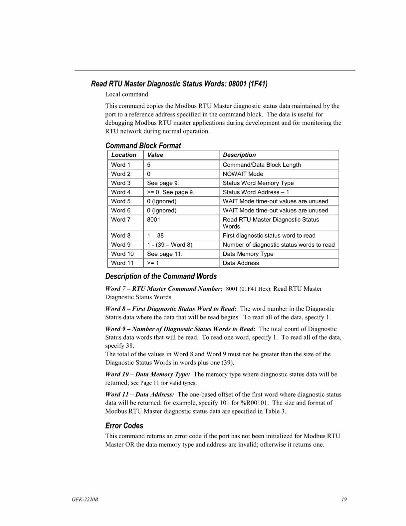
Read RTU Master Diagnostic Status Words: 08001 (1F41) Local command
This command copies the Modbus RTU Master diagnostic status data maintained by the port to a reference address specified in the command block. The data is useful for debugging Modbus RTU master applications during development and for monitoring the RTU network during normal operation.
Command Block Format Location Value Description Word 1 5 Command/Data Block Length Word 2 0 NOWAIT Mode Word 3 See page 9. Status Word Memory Type Word 4 >= 0 See page 9. Status Word Address – 1 Word 5 0 (Ignored) WAIT Mode time-out values are unused Word 6 0 (Ignored) WAIT Mode time-out values are unused Word 7 8001 Read RTU Master Diagnostic Status
Words Word 8 1 – 38 First diagnostic status word to read Word 9 1 - (39 – Word 8) Number of diagnostic status words to read Word 10 See page 11. Data Memory Type Word 11 >= 1 Data Address
Description of the Command Words Word 7 – RTU Master Command Number: 8001 (01F41 Hex): Read RTU Master Diagnostic Status Words
Word 8 – First Diagnostic Status Word to Read: The word number in the Diagnostic Status data where the data that will be read begins. To read all of the data, specify 1.
Word 9 – Number of Diagnostic Status Words to Read: The total count of Diagnostic Status data words that will be read. To read one word, specify 1. To read all of the data, specify 38. The total of the values in Word 8 and Word 9 must not be greater than the size of the Diagnostic Status Words in words plus one (39).
Word 10 – Data Memory Type: The memory type where diagnostic status data will be returned; see Page 11 for valid types.
Word 11 – Data Address: The one-based offset of the first word where diagnostic status data will be returned; for example, specify 101 for %R00101. The size and format of Modbus RTU Master diagnostic status data are specified in Table 3.
Error Codes This command returns an error code if the port has not been initialized for Modbus RTU Master OR the data memory type and address are invalid; otherwise it returns one.

20 Modbus RTU Master Communications - December 2003 GFK-2220B
Send RTU Read/Force/Preset Query: 08002 (1F42) Remote command
This command sends a Modbus RTU Master Read, Force, Preset, or Report Device Type query message as specified in the command/data block.
Command Block Format Location Value Description
Word 1 7 Command/Data Block Length Word 2 0 NOWAIT Mode Word 3 See page 9. Status Word Memory Type Word 4 >= 0 See page 9. Status Word Address – 1 Word 5 0 (Ignored) WAIT Mode time-out values are unused Word 6 0 (Ignored) WAIT Mode time-out values are unused Word 7 8002 Send RTU Master Read/Force/Preset Query Word 8 0 - 247 Target RTU Device Address Word 9 See table below. RTU Function Code Word 10 See below. RTU Data Address/Start Address Word 11 See below. RTU Number of Points or 16-bit Registers Word 12 See below. Data Memory Type of source (for Force,/Preset
queries) or destination (for Read queries) Word 13 >= 1 Data Address of source (for Force,/Preset
queries) or destination (for Read queries)
Description of the Command Words Word 7 – RTU Master Command Number: 8002 (01F42 Hex): Send RTU Read/Force/Preset Query
Word 8 – Target RTU Device Address: This is the 8-bit device address of the Modbus RTU slave to which the query is addressed, using Modbus addressing. Address zero is the broadcast address. Any query sent to the broadcast address should not result in a response. Valid device addresses are in the range 1 through 247 inclusive. Schneider/Modicon has reserved the values 248 to 255.
Word 9 – RTU Function Code: This is the 8-bit function code for the query. The following function codes are supported; all others are invalid.
Function Code Value
Dec. Hex. Function Name
Slave Reference
Type
Valid as Broadcast
Query?
1 01 Read Output Table %Q No 2 02 Read Input Table %I No 3 03 Read Registers %R No 4 04 Read Analog Inputs %AI No 5 05 Force Single Output %Q Yes 6 06 Preset Single Register %R Yes 7 07 Read Exception Status %Q No
15 0F Force Multiple Outputs %Q Yes 16 10 Preset Multiple Registers %R Yes 17 11 Report Device Type N/A No 67 43 Read Scratch Pad Memory N/A No

GFK-2220B 21
Word 10 – RTU Data Address/Start Address: The one-based offset into the target reference data type on the slave that specifies:
� The data location for the Force Single Output and Preset Single Register function codes;
� The start of the data range for Read Output Table, Read Input Table, Read Registers, Read Analog Inputs, Force Multiple Outputs and Preset Multiple Registers function codes; and
� The starting byte number for the Read Scratch Pad Memory function code.
For example, specify 101 for either %R00101 in a GE Fanuc PLC or Holding Register 4101/40101 in a Schneider/Modicon PLC.
This word is ignored for the Read Exception Status and Report Device Type function codes.
Word 11 – RTU Number of Points/Registers/Byte: The number of 1-bit points (Read Output Table, Read Input Table, Force Multiple Outputs) or 16-bit registers (Read Registers, Read Analog Inputs, Preset Multiple Registers) that will be sent to the slave in a Force/Preset Multiple query or requested from the slave in a Read query, or the number of bytes that will be requested in a Read Scratch Pad Memory request.
This word is ignored for the Force Single Output, Preset Single Register, Read Exception Status and Report Device Type function codes.
Note that the Byte Count field in Force/Preset Multiple queries will be calculated from RTU Number of Points/Registers according to the size of the target reference type associated with the RTU Function Code.
The Modbus specification limits the Number of Points/Register/Bytes:
Reference Class Range
Discrete Inputs/Outputs 1 to 2000 (7D0h) Read/Preset 16-bit registers 1 to 125 (7Dh) †
† Note: the current Modbus RTU specification specifies “approximately 120 registers” for the Preset Multiple Registers function code. Some slave devices may reject queries that are valid for a GE Fanuc master device.
Word 12 –Data Memory Type: This is the memory reference data type in the local PLC for the source of transmitted data in Force/Preset queries or the destination where response data is copied for Read queries. Page 9 of this document specifies the valid types.
Word 13 – Data Address: This is the one-based offset in the local PLC of the source data address for Force/Preset queries or the destination data address for Read queries. For example, specify 101 for %R00101.
The entire range of data references defined by the Data Memory Type, Data Address, and Number of Points/Registers/Bytes must be valid in the local PLC. For example, if the local PLC is configured with a Register Memory size of 2048 words, and the Number of Registers in a Read Registers query is 120, then the largest valid Data Address is %R01929 (2048 – 120 + 1).

22 Modbus RTU Master Communications - December 2003 GFK-2220B
Send RTU Diagnostic Query: 08003 (1F43) Remote command
This command sends one of the following Modbus RTU Master queries as specified in the command/data block: Loopback/Maintenance
Command Block Format Location Value Description Word 1 5 Command/Data Block Length Word 2 0 NOWAIT Mode Word 3 See page 9. Status Word Memory Type Word 4 >= 0 See page 9. Status Word Address – 1 Word 5 0 (Ignored) WAIT Mode time-out values are unused Word 6 0 (Ignored) WAIT Mode time-out values are unused Word 7 8003 Send RTU Master Diagnostic Query Word 8 0 - 247 Target RTU Device Address Word 9 See below. RTU Function Code Word 10 See below. Loopback/Maintenance Diagnostic Code Word 11 See below. Loopback/Maintenance Data
Description of the Command Words Word 7 – RTU Master Command Number: 8003 (01F43 Hex): Send RTU Diagnostic Query
Word 8 – Target RTU Device Address: This is the 8-bit device address of the Modbus RTU slave device to which the RTU query is addressed, using the Modbus addressing scheme. Address zero is the broadcast address. Any query sent to the broadcast address should not result in a response.
Valid device addresses are in the range 1 through 247 inclusive. Schneider/Modicon has reserved the values 248 to 255.

GFK-2220B 23
Word 9 – RTU Function Code: This is the 8-bit function code for the Modbus RTU Query. The following function codes will be supported; all others are invalid.
Function Code Value Function Name
Valid as Broadcast
Query 8 (08h) Loopback/Maintenance No/Yes
Word 10 – Loopback/Maintenance Diagnostic Code: The following diagnostic codes are supported for Loopback/Maintenance queries; all others are invalid.
Diagnostic Code Value Description
Valid as Broadcast
Query 0 Return Query Data – target slave should respond
by sending a duplicate of the query message. No
1 Initiate Communication Restart – target slave(s) disable Listen-only Mode (if enabled).
Yes
4 Force Listen-only Mode – target slave(s) enable Listen-only Mode
Yes
Word 11 – Loopback/Maintenance Data: The following data values are required in Loopback/Maintenance queries; all others are invalid.
Diagnostic Code Value Loopback/Maintenance Data Value
0 Any 16-bit unsigned value: 0 - 65,535 (0 - 0FFFFh) 1 Clear Communications Event Log:
Do not clear Event Log: 0 (0000h) 65280 (FF00h)
4 0

24 Modbus RTU Master Communications - December 2003 GFK-2220B
Send 32-Bit RTU Read/Force/Preset Query: 08004 (1F44) Remote command
This command sends a Modbus RTU Master Read, Force, Preset, or Report Device Type query message as specified in the command/data block. For function codes 3, 4, 6 and 16, 32-bit register data is assumed. This command should be used only to exchange register data with remote terminal units that use 32-bit registers – for example, the Daniels Industries Model 2500 Flow Computer.
Command Block Format Location Value Description Word 1 7 Command/Data Block Length Word 2 0 NOWAIT Mode Word 3 See page 9. Status Word Memory Type Word 4 >= 0 See page 9. Status Word Address – 1 Word 5 0 (Ignored) WAIT Mode time-out values are unused Word 6 0 (Ignored) WAIT Mode time-out values are unused Word 7 8004 Send 32-Bit RTU Master Read/Force/Preset
Query Word 8 0 – 247 Target RTU Device Address Word 9 See table below. RTU Function Code Word 10 See below. RTU Data Address/Start Address Word 11 See below. RTU Number of Points or 32-bit Registers Word 12 See below. Data Memory Type of source (for Preset
queries) or destination (for Read queries) Word 13 >= 1 Data Address of source (for Preset queries) or
destination (for Read queries)
Description of the Command Words Word 7 – RTU Master Command Number: 8004 (01F44 Hex): Send 32-Bit RTU Read/Preset Query
Word 8 – Target RTU Device Address: This is the 8-bit device address of the Modbus RTU slave to which the query is addressed, using Modbus addressing. Address zero is the broadcast address. Any query sent to the broadcast address should not result in a response. Valid device addresses are in the range 1 through 247 inclusive. Schneider/Modicon has reserved the values 248 to 255.
GFK-2220B 25
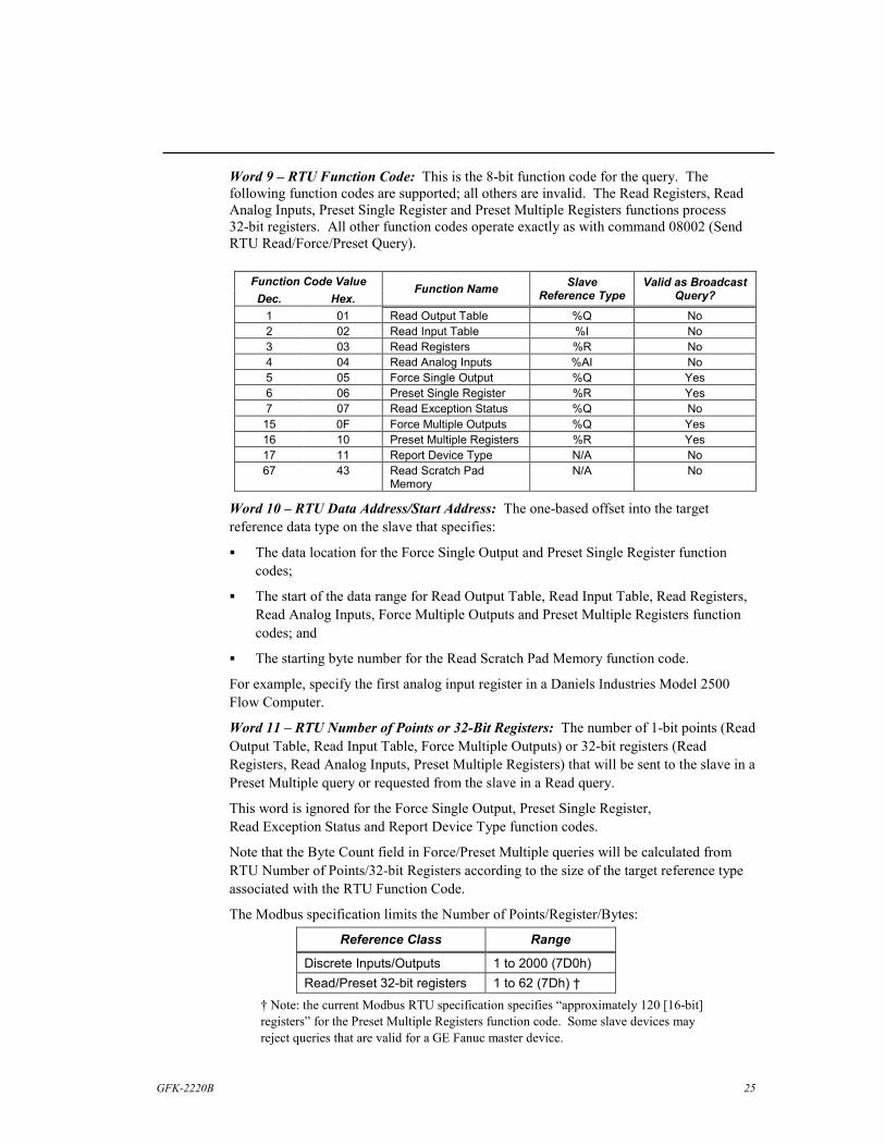
Word 9 – RTU Function Code: This is the 8-bit function code for the query. The following function codes are supported; all others are invalid. The Read Registers, Read Analog Inputs, Preset Single Register and Preset Multiple Registers functions process 32-bit registers. All other function codes operate exactly as with command 08002 (Send RTU Read/Force/Preset Query).
Function Code Value Dec. Hex.
Function Name Slave Reference Type
Valid as Broadcast Query?
1 01 Read Output Table %Q No 2 02 Read Input Table %I No 3 03 Read Registers %R No 4 04 Read Analog Inputs %AI No 5 05 Force Single Output %Q Yes 6 06 Preset Single Register %R Yes 7 07 Read Exception Status %Q No 15 0F Force Multiple Outputs %Q Yes 16 10 Preset Multiple Registers %R Yes 17 11 Report Device Type N/A No 67 43 Read Scratch Pad
Memory N/A No
Word 10 – RTU Data Address/Start Address: The one-based offset into the target reference data type on the slave that specifies:
� The data location for the Force Single Output and Preset Single Register function codes;
� The start of the data range for Read Output Table, Read Input Table, Read Registers, Read Analog Inputs, Force Multiple Outputs and Preset Multiple Registers function codes; and
� The starting byte number for the Read Scratch Pad Memory function code.
For example, specify the first analog input register in a Daniels Industries Model 2500 Flow Computer.
Word 11 – RTU Number of Points or 32-Bit Registers: The number of 1-bit points (Read Output Table, Read Input Table, Force Multiple Outputs) or 32-bit registers (Read Registers, Read Analog Inputs, Preset Multiple Registers) that will be sent to the slave in a Preset Multiple query or requested from the slave in a Read query.
This word is ignored for the Force Single Output, Preset Single Register, Read Exception Status and Report Device Type function codes.
Note that the Byte Count field in Force/Preset Multiple queries will be calculated from RTU Number of Points/32-bit Registers according to the size of the target reference type associated with the RTU Function Code.
The Modbus specification limits the Number of Points/Register/Bytes:
Reference Class Range
Discrete Inputs/Outputs 1 to 2000 (7D0h) Read/Preset 32-bit registers 1 to 62 (7Dh) †
† Note: the current Modbus RTU specification specifies “approximately 120 [16-bit] registers” for the Preset Multiple Registers function code. Some slave devices may reject queries that are valid for a GE Fanuc master device.

26 Modbus RTU Master Communications - December 2003 GFK-2220B
Word 12 –Data Memory Type: This is the memory reference data type in the local PLC for the source of transmitted data in Preset queries or the destination where response data is copied for Read queries. Page 11 of this document specifies the valid types.
Word 13 – Data Address: This is the one-based offset in the local PLC of the source data address for Preset queries or the destination data address for Read queries. For example, specify 101 for %R00101.
The entire range of data references defined by the Data Memory Type, Data Address, and Number of Points/Registers/Bytes must be valid in the local PLC. For example, if the local PLC is configured with a Register Memory size of 2048 words, and the Number of 32-bit Registers in a Read Registers query is 60, then the largest valid Data Address is %R01929 (2048 – (2*60) + 1).
Byte/Word Order The standard Modbus RTU byte order for 16-bit registers is extended to 32-bit registers. The Data Memory Type and Data Address are assumed to be a reference to DWord data. For Preset functions, the most significant byte of the first DWord at the source data reference is transmitted first, followed by the second most significant byte, the third most significant byte and the least significant byte. For Read functions, the first data byte that is received is stored as the most significant byte of the first DWord at the destination data reference; the next received byte is stored as the second most significant byte, etc.
When the source/destination DWord data in the local PLC is displayed as Words, the most significant Word of each DWord is shown at the reference address above the location of the least significant Word. For example, assume that a Read Registers query returns one 32-bit register, and the destination data reference is %R00001.
Received Data Bytes (First byte at left): 16#01, 16#23, 16#45, 16#67
DWord stored to %R00001: 16#01234567
Word displayed at %R00001: 16#4567
Word displayed at %R00002: 16#0123

GFK-2220B 27
Error Codes for RTU Master Commands Symbolic values for major and minor error codes and their meanings are shown in the table below. See also the table of error codes for the Initialize RTU Master Port command on p. 13.
Major Error Code Minor Error Code
Numeric Status Value
Description
COMMREQ_OK None 0001h The RTU Master COMMREQ command has succeeded.
NOT_A_COMREQ 0103h A Message received from CPU is not a COMREQ. WAIT_COMREQ 0203h WAIT-mode COMREQs are not supported. UNSUPP_COMREQ_CMD 0303h The COMREQ Command is unsupported. COMREQ_LEN_INVALID 0403h The COMREQ data length is too small. PORT_DATA_INVALID 0503h Port Setup COMREQ data is invalid. DEV_ADDRESS_INVALID 0603h The RTU slave device is invalid. FUNC_CODE_UNSUPPORTED 0703h The RTU function code is not supported.
PARAMETER_ ERROR
FUNC_INVALID_FOR_BCAST 0803h The specified function code requires a response. DIAG_CODE_UNSUPPORTED 0903h The Diagnostic code is unsupported in
Loopback/Maintenance queries. DATA_START_INVALID 0A03h The specified data starting location is invalid. DATA_QUANTITY_INVALID 0B03h The specified data quantity results in an invalid
message length. DATA_MEM_TYPE_INVALID 0C03h The specified memory type for the data
source/destination is invalid for local PLC CPU. DATA_MEM_OFFSET_INVALID 0D03h The specified memory location for the data
source/destination is invalid for local PLC CPU. STATUS_MEM_TYPE_INVALID 0E03h The specified status memory type invalid for the local
PLC CPU. STATUS_MEM_ OFFSET_INVALID
0F03h The specified status memory location invalid for the local PLC CPU.
DSW_RANGE_INVALID 1003h The specified Diagnostic Status Words starting location or length is invalid.
BUF_ALLOC_ERROR 1103h An error occurred during an attempted system memory allocation.
PARITY_ERROR 0104h Parity error detected, response discarded. FRAMING_ERROR 0204h Framing error detected, response discarded. OVERRUN_ERROR 0204h Over-run error detected, response discarded. SHORT_RSP_ERROR 0304h Incomplete response detected, response discarded.
PORT_ERROR
CRC_ERROR 0404h CRC error detected, response discarded. QUERY_XMIT_TIMEOUT 0105h HARDWARE flow control is in use, and CTS was not
detected within the specified time. TIMEOUT_ ERROR
RESPONSE_TIMEOUT 0205h A response was not received within the specified time.
STATUS_WORD_WRITE_ERR 0106h An error occurred while writing the COMREQ Status Word.
DATA_WRITE_ERR 0206h An error occurred while writing to RTU Data Memory.
MEM_ERROR
DATA_READ_ERR 0306h An error occurred while reading from RTU Data Memory.

28 Modbus RTU Master Communications - December 2003 GFK-2220B
Major Error Code Minor Error Code
Numeric Status Value
Description
INVALID_RESPONSE_CRC 0107h The response CRC-16 is incorrect. INVALID_RESPONSE_LENGTH 0207h The response length is incorrect. INVALID_RESPONSE_ADDR 0307h The response device address is incorrect. INVALID_RESPONSE_FUNC 0407h The response function code is incorrect.
RESPONSE_ ERROR
INVALID_LOOPBACK_RESP 0507h A Loopback/Maintenance response data is incorrect.
ILLEGAL_FUNCTlON 0108h The Modbus slave detected a function code it does not support.
ILLEGAL_DATA_ADDRESS 0208h The Modbus slave detected a data address it does not support.
ILLEGAL_DATA_VALUE 0308h The Modbus slave detected a data value that is not allowable.
SLAVE_DEVlCE_FAILURE 0408h The Modbus slave encountered an unrecoverable error while attempting to complete the requested function.
ACKNOWLEDGE 0508h SLAVE_DEVlCE_BUSY 0608h
RCVD_ EXCEPTION
NEGATlVE_ACKNOWLEDGE 0708h
This exception code does not apply to the functions supported by this implementation.
MEMORY_PARlTY_ERROR 0908h The slave detected a parity error in extended memory.
GFK-2220B 29
Example Application The following example illustrates the basic programming principles used by Modbus RTU Master applications. The example is provided in ladder diagram (LD) logic. It is available from the GE Fanuc PLC Technical Support web site in versions for IC693CPU363 and VersaMax modular CPUs. Application folders for CIMPLICITY Machine Edition Logic Developer - PLC, VersaPro, and Logicmaster 90-30 (IC693CPU363 only) are available.
The example provides RTU Master communications only. It can be used as a framework for developing actual applications. Alternatively, the example program blocks can be imported into other application folders and modified as needed.
Each of the program blocks in the example is described below.
CIMPLICITY and Logicmaster™ are trademarks of GE Fanuc Automation.

30 Modbus RTU Master Communications - December 2003 GFK-2220B
MAIN Block Example The main block, named _MAIN, simply calls each of the other program blocks in turn. RTUINIT sets up serial port 2 for Modbus RTU master operation. Once that process completes, the normally-closed contact %T00003 opens, and RTUINIT is never called again as long as the PLC remains in Run mode.
RTUSTAT periodically reads the RTU master diagnostic status word (DSW) data from port 2. This data is useful during application development but has little utility once the system goes into operation.
RTU_SLV sends a sequence of RTU queries to specified RTU slave devices from port 2. When an RTU response is received or times out, the next query in the sequence is sent immediately. When the last response in the sequence is received or times out, the first query is sent again.
RTU_TMR is similar to RTU_SLV. A timer is added that controls the minimum time interval between successive transmissions of the first query in the sequence.
_MAIN Program Block
At most two of the blocks that periodically issue COMMREQ commands to the same RTU master serial port may be called. In the logic shown above, blocks RTUSTAT and RTU_TMR are always called, while RTU_SLV is never called. An alternative design could call two blocks similar to RTU_SLV (or to RTU_TMR), one to send queries that request input data from a group of slaves, and the other to send outputs to another group of slaves.

GFK-2220B 31
RTUINIT Example Block RTUINIT is called once, immediately after the PLC enters Run mode. In the logic shown below, the BLKMOV function blocks initialize the status data and data block for the COMMREQ that will set up serial port 2 for RTU master operation. The port is initialized as follows:
COMMREQ status value: Zero COMMREQ status location: %R01001 Protocol: Modbus RTU Mode: Master Data rate: 19,200 bits/Sec. Parity: Even Flow control: None Turnaround delay: Zero Response message time-out: STANDARD (0.5 Sec.) Bits per Character: 8 (Not configurable) Stop Bits: 1 (Not configurable) Port Interface: Not configurable for CPU ports, Port 1: RS-232, Port 2: RS-485 Half-Duplex Mode: 2-Wire (Not configurable) Character-gap time-out: Default RTS Drop Delay: Zero
RTUINIT Program Block, Part 1

32 Modbus RTU Master Communications - December 2003 GFK-2220B
The next part of the RTUINIT block includes a two-second timer in rung 6 that delays the port setup COMMREQ. Temporary contact %T00001 is automatically cleared on first scan, and the timer function block begins timing immediately. When it times out, it sets the on-transition contact %T00002 that resets the timer and also sets %T00001. The latter prevents the timer from running.
RTUINIT Program Block, Part 2
The serial port setup COMMREQ function block in rung 9 is activated once on the PLC scan when the timer shown above expires. If a COMMREQ fault occurs, %T00001 is reset so that the delay timer will start again.
A COMMREQ fault will occur when the combination of COMMREQ SYS ID and TASK values is invalid. Note that the correct SYS ID value for IC693CPU363 is 1 (rack zero, slot one), while the correct value for VersaMax modular CPUs is 0 (rack zero, slot zero).
A COMMREQ fault will also occur in VersaMax modular CPUs when an invalid reference location is specified for the COMMREQ status.
If no COMMREQ fault occurs, the EQ_INT function block in rung 11 waits for the value in the COMMREQ status word at %R01001 to be set to 1 by the serial port and then sets %T00003, the contact that indicates initialization has completed successfully.

GFK-2220B 33
If an error occurs, an error code value may be returned to the COMMREQ status word location. Error status values often occur during application development because of errors in the serial port configuration data for the COMMREQ. Once the configuration data is correct, however, the port should never return an error status. To facilitate error diagnosis, the status value is visible from the program editor at the IN1 input of the EQ_INT function block shown below. See the PARAMETER_ERROR section of the Error Codes table in this document for information on error status values for this COMMREQ.
RTUSTAT Example Block RTUSTAT is called from _MAIN to read the RTU master diagnostic status word (DSW) data. RTUSTAT periodically sends a COMMREQ to the RTU master serial port.
The logic shown below includes the BLKMOV function blocks that initialize the COMMREQ data. The data specifies %R01031 as the COMMREQ status location and requests all 38 of the status words, starting at the first word. The destination for the status data is %R00961 - %R00998.
RTUSTAT Program Block, Part 1

34 Modbus RTU Master Communications - December 2003 GFK-2220B
RTUSTAT Program Block, Part 2 The next section of example logic includes the one-second timer that controls the COMMREQs. The timer starts after RTU master initialization completes. When the timer expires, the NE_INT function block tests the COMMREQ status location to determine whether the value is zero because the previous COMMREQ has not completed.
The first time the timer expires, the status location will contain its initialization value (one). The NE_INT output will turn on, setting the status location to zero and also setting coil %T00004, the COMMREQ trigger.
%T00004 resets the one-second timer and activates the COMMREQ function block, which sends the DSW data request to serial port 2. When the COMMREQ completes successfully, the status location in %R01031 will be set to one.
On the next time-out of the one-second timer, the cycle will begin again.

GFK-2220B 35
RTU_SLV Example Block RTU_SLV is called from _MAIN to send a sequence of Modbus RTU query messages to RTU slave devices. Each query in the sequence is sent immediately when the previous response arrives. When the last response of the sequence is received, the sequence repeats immediately. The example sequence contains five queries, but the sequence can be expanded to contain any number.
The logic shown below includes the BLKMOV function block that initializes the portion of the COMMREQ data that is common to all the queries in the sequence. The data specifies %R01051 as the COMMREQ status location.
RTU_SLV Program Block, Part 1
The NE_INT instruction above tests the value in the COMMREQ status location. When a non-zero value is detected, the status is set to zero and the COMMREQ trigger contact, %T00005, is turned on. The status location contains one after initialization on the first scan, and after each query COMMREQ completes.

36 Modbus RTU Master Communications - December 2003 GFK-2220B
The logic below shows two BLKMOV instructions that initialize COMMREQ data for the first two queries in the sequence. Data for the final three queries of the sequence is not shown here. However, you can see it by opening the example program in an LD program editor such as CIMPLICITY Machine Edition Logic Developer – PLC.
All the queries share the same range of %R memory for COMMREQ status and data, but each one has a separate block for data sent to or received from its target Modbus RTU slave.
The first BLKMOV instruction shown below is activated when the COMMREQ trigger, %T00005, and the enabling contact for the first query, %T00097, are both on. This initializes the COMMREQ data block for the first query of the sequence. Similarly, the second query is initialized when %T00005 and %T00098 are both on. Contacts %T00099 through %T00101 permit initialization of the third, fourth and fifth queries, respectively.
RTU_SLV Program Block, Part 2

GFK-2220B 37
The logic shown below sends each COMMREQ in sequence. The COMMREQ instruction is enabled by the trigger contact, %T00005. If a COMMREQ fault occurs, coil %T00081 is set. You can add logic that is enabled by a %T00081 contact to take whatever action is appropriate for your application.
The SHFR_BIT instruction is used to step to the next query in the sequence each time a COMMREQ is sent. All of the %T contacts are set to off when the PLC enters RUN mode, including the range %T00097 through %T00101 used by SHFR_BIT. The first rung of RTU_SLV (shown on page 35) switches %T00097 on during the first logic scan. The SHFR_BIT instruction shifts this one bit to the next higher bit location each time %T00005 fires. When the one bit has been shifted the number of times specified by the SHFR_BIT length parameter, it returns to %T00097, and the sequence repeats.
The sequence can be made arbitrarily long by changing the SHFR_BIT length parameter. One additional BLKMOV instruction (similar to those in the previous section of logic) will be required for each added sequence step.
RTU_SLV Program Block, Part 3

38 Modbus RTU Master Communications - December 2003 GFK-2220B
This example RTU_SLV block does not check the COMMREQ status for errors. Additional logic, not shown here, can check the COMMREQ status location for error values. Here is a suggested design outline that distinguishes programming errors from network errors.
1. Mask the minor error code (most significant byte) using an AND_WORD instruction with the COMMREQ status word and the constant 00FF hexadecimal (16#00FF) as inputs. The result contains only the major error code. Specify an unused register as the output.
2. Test the major error code (least significant byte) for the decimal value 3 (COMMREQ parameter error) using an EQ_INT instruction. This major error is caused by a programming error or an incompatibility between the application and the configured memory ranges of the PLC. It must be corrected in the application program or PLC hardware configuration.
3. All other major errors are caused by conditions that the application needs to detect and handle while running – for example, temporary noisy network conditions, loss of power on a Modbus RTU slave, slave hardware configuration changes, etc. Note however, that major error code 8 indicates that a Modbus RTU response contained an exception. Some of these exceptions can be caused by errors in the query data specified in the COMMREQ data block.
RTU_TMR Example Block RTU_TMR is similar to RTU_SLV and is not shown here. It adds an on-delay timer to control the minimum time between the start of successive sequences of queries and responses. The timer adds a state (one bit) at the start of the SHFR_BIT sequence to reset and start the timer. Another state is added at the end of the sequence to wait until the timer reaches its programmed time-out value. After the time-out, the sequence begins again.