Modbus Installation and operating instructions for the ... · VA 5xx Modbus RTU Installation V1.03...
23
VA 5xx Modbus RTU Installation V1.03 Page 1 of 23 Modbus Installation and operating instructions for the sensors VA 500 / VA 520 und VA 550 / VA 570 EN - English
Transcript of Modbus Installation and operating instructions for the ... · VA 5xx Modbus RTU Installation V1.03...

VA 5xx Modbus RTU Installation V1.03 Page 1 of 23
Modbus Installation and operating instructions for the sensors
VA 500 / VA 520 und VA 550 / VA 570
EN - English
VA 5xx Modbus RTU Installation V1.03 Page 2 of 23
I. Foreword
Dear customer,
thank you very much for deciding in favour of the VA 500 / VA 520 / VA 550 / VA570. Please read this installation and operation manual carefully before mounting and initiating the device and follow our advice. A riskless operation and a correct functioning of the VA 500 / VA 520 / VA 550 / VA570 are only guaranteed in case of careful observation of the described instructions and notes
.
Geschäftsstelle Süd/Sales Office South
Zindelsteiner Str. 15 D-78052 VS-Tannheim
Tel.: +49 (0) 7705 978 99 0 Fax: +49 (0) 7705 978 99 20
Mail: [email protected] Web: http://www.cs-instruments.com
Geschäftsstelle Nord/Sales Office North
Am Oxer 28c D-24955 Harrislee
Tel.: +49 (0) 461 700 20 25 Fax: +49 (0) 461 700 20 26
Mail: [email protected] Web: http://www.cs-instruments.com

Inhalstverzeichnis
VA 5xx Modbus RTU Installation V1.03 Page 3 of 23
II. Table of Content
Modbus Installation and operating instructions for the sensors ..................................... 1
VA 500 / VA 520 und VA 550 / VA 570 ............................................................................... 1
I. Foreword ....................................................................................................................... 2
II. Table of Content ........................................................................................................ 3
1 Instructions ................................................................................................................... 5
1.1 Definition and abbreviation .................................................................................................... 5
1.2 References ............................................................................................................................... 5
2 Technical data Modbus VA 5xx .................................................................................... 6
2.1 VA 5xx MODBUS RTU specificationn ................................................................................... 6
2.1 General Modbus Information ................................................................................................. 6 2.1.1 Serial transmission modes (RTU) ...................................................................................... 6
3 Installation ..................................................................................................................... 7
3.1 RS485 Bus Wiring (Modbus RTU) –VA 500 / VA520 ............................................................ 7 3.1.1 Termination VA 500 / VA 520 ............................................................................................ 7 3.1.2 Bias .................................................................................................................................... 7 In order to avoid undefined bus levels, at any llocation on the bus, a bias network, one resistor to VCC (Modbus A) as well as to GND (Modbus B), has to be used. .................................................. 7
3.2 RS485 Bus Verdrahtung (Modbus RTU) – Anschlussplan VA 550 / VA570 ..................... 8 3.2.1 Termination VA 550 / VA 570 ............................................................................................ 8 3.2.2 Bias .................................................................................................................................... 8 In order to avoid undefined bus levels, at any llocation on the bus, a bias network, one resistor to VCC (Modbus A) as well as to GND (Modbus B), has to be used. .................................................. 8
4 Modbus RTU communication settings ........................................................................ 9
4.1 Accessing and changing Modbus settings .......................................................................... 9
5 Modbus TCP communication settings ........................................................................ 9
6 Modbus addressing model ........................................................................................... 9
6.1 Function Code 3 (Read holding register) ........................................................................... 10
6.2 Function code 16 (Write multiple registers) ....................................................................... 10
7 Modbus Holding Register ............................................................................................11
7.1 Basic Values Register (1…1000) ....................................................................................... 11
7.2 Values register (1001….1500) ............................................................................................. 12
7.3 Device settings register ....................................................................................................... 18 7.3.1 Modbus Settings (2001…2005) .................................................................................... 18 7.3.2 Display Settings (2007…2009) ..................................................................................... 18 7.3.3 Device Settings (2021…2063) ..................................................................................... 19
7.4 Data format test register (64001… 64003) ........................................................................ 21

VA 5xx Modbus RTU Installation V1.03 Side 4 of 23
8 Appendix ......................................................................................................................22
8.1 APPENDIX A - Exception codes .......................................................................................... 22
9 Change history .............................................................................................................23
VA 5xx Modbus RTU Installation V1.03 Page 5 of 23
1 Instructions
This manual is intended to provide instructions for the installation and use of the FA 5xx
MODBUS function. The FA 5xx MODBUS function can let the MODBUS master device to
read out the online measurement values.
This manual is not intended to be a complete tutorial on the MODBUS RTU protocol, and it
is assumed the end user already has a general working knowledge of MODBUS RTU
Communications, especially in respect of master station configuration and operation.
However an overview is included in the following section to explain some of the
fundamental aspects of the protocol.
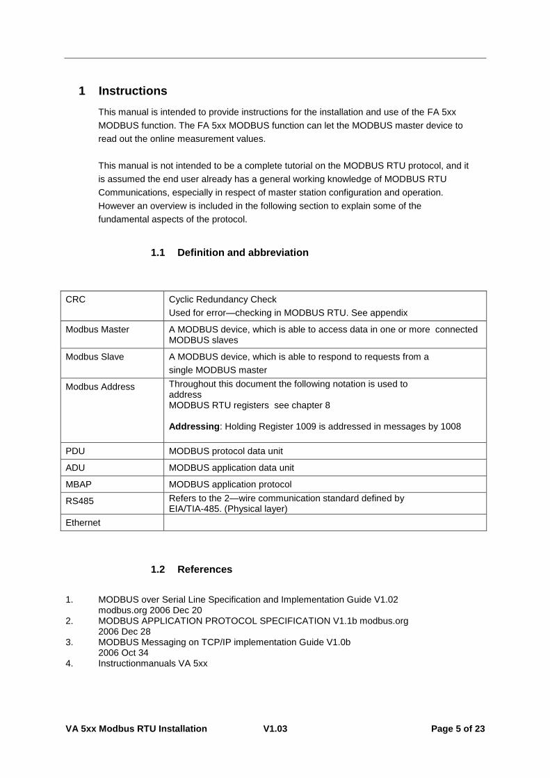
1.1 Definition and abbreviation
CRC
Cyclic Redundancy Check
Used for error—checking in MODBUS RTU. See appendix
Modbus Master A MODBUS device, which is able to access data in one or more connected MODBUS slaves
Modbus Slave A MODBUS device, which is able to respond to requests from a
single MODBUS master
Modbus Address Throughout this document the following notation is used to address MODBUS RTU registers see chapter 8 Addressing: Holding Register 1009 is addressed in messages by 1008
PDU MODBUS protocol data unit
ADU MODBUS application data unit
MBAP MODBUS application protocol
RS485 Refers to the 2—wire communication standard defined by EIA/TIA-485. (Physical layer)
Ethernet
1.2 References
1. MODBUS over Serial Line Specification and Implementation Guide V1.02 modbus.org 2006 Dec 20
2. MODBUS APPLICATION PROTOCOL SPECIFICATION V1.1b modbus.org 2006 Dec 28
3. MODBUS Messaging on TCP/IP implementation Guide V1.0b 2006 Oct 34
4. Instructionmanuals VA 5xx

VA 5xx Modbus RTU Installation V1.03 Side 6 of 23
2 Technical data Modbus VA 5xx
2.1 VA 5xx MODBUS RTU specificationn
Device type Slave
Baud Rates 1200,2400, 4800, 9600, 19200, 38400 bps
Device address range 1...247
Electrical Interface RS485, 2 wire
Protocol RTU
Supported function code 3 read holding register
16 write multiple register
Broadcast No
Standard Modbus over serial line V1.02
2.1 General Modbus Information
The DS 500 Modbus module complies with the Modbus serial line protocol [Reference 1].
Among other things this implies a master-slave protocol at level 2 of the OSI model. One
node (the master) issues explicit commands to one of the ,,sIave"-nodes and processes
responses. Slave nodes will not transmit data without a request from the master node, and
do not communicate with other slaves.
Modbus is a mono master system, which means that only one master can be connected
at the time.
2.1.1 Serial transmission modes (RTU)
The VA 5xx Modbus mode support only one serial transmission modes; the RTU
mode. The transmission mode defines the bit contents of message fields
transmitted serially on the line. It determines how information is packed into the message
fields and decoded.
The transmission mode and serial port parameters must be the same for all devices on a
Modbus serial line.
RTU mode Modbus Application Data Unit (ADU) frame is shown below, and is valid for
both requests and responses.
Slave address Function code Data CRC
1 byte 1byte 0 up to 252 byte(s) 2 bytes
Table 1
Further details of the Modbus protocol can be found in Reference 1 and 2.

VA 5xx Modbus RTU Installation V1.03 Side 7 of 23
3 Installation
3.1 RS485 Bus Wiring (Modbus RTU) –VA 500 / VA520
Slave 1 Slave n
A
B
Common
T TR R
Master
TR
Anschlußstecker AVA 500 / VA 520
Pin 2Pin 4
Pin 3
68
0R
68
0R
12
0R
Terminierung / Bias
3.1.1 Termination VA 500 / VA 520
Note: In case the VA 500 / VA 520 is the last device in the RS485 network then a termination is required. To be done either with
a.) Internal DIP Switch
b.) 120R between (between Pin 2 and Pin 4) of connector plug A
3.1.2 Bias
In order to avoid undefined bus levels, at any llocation on the bus, a bias network, one resistor to VCC (Modbus A) as well as to GND (Modbus B), has to be used.

VA 5xx Modbus RTU Installation V1.03 Side 8 of 23
3.2 RS485 Bus Verdrahtung (Modbus RTU) – Anschlussplan VA 550 / VA570
Slave 1 Slave n
A
BCommon
T TR R
Master
TR
Anschlußstecker X2VA 550 / VA 570
Pin 3Pin 1
Pin 2
3.2.1 Termination VA 550 / VA 570
Note: In case the VA 550 / VA 570 is the last device in the RS485 network then a termination with 120R between (between Pin 1 and Pin 3) at connector X2 is necessary
3.2.2 Bias
In order to avoid undefined bus levels, at any llocation on the bus, a bias network, one resistor to VCC (Modbus A) as well as to GND (Modbus B), has to be used.
Bus cable:
Only cables according to the recommendations of EIA 485 standard should be used. A
maximum of 64 devices may be connected to one segment. The bus cable must be laid at
a distance of at least 20 cm from other cables. It should be laid in a separate, conductive,
and earthed cable trunking. It must be ensured that no potential differences occur between
the individual devices on the bus.
Cable specification:
Impedance: 135 -165 Ohm @ 3 to 20 Mhz
Cable capacity: < 30pF/m
Cable diameter: > 0.64 mm
Cross section: > 0.34 mm2, conforms to AWG 22
Loop resistance < 110 Ohm per km
Screening: Cu shielding braid or shielding braid and shielding foil

VA 5xx Modbus RTU Installation V1.03 Side 9 of 23
4 Modbus RTU communication settings
Before communication with the master, baudrate, address, and framing must be defined
4.1 Accessing and changing Modbus settings
The Modbus communication settings could be changed by using either the PC service software from CS Instruments, the data loggers DS 400, DS 500 or the handheld device PI 500 Note:
It is recommended NOT to use the default address in a multi-slave network. It is of great
importance to ensure at the time of the procedure of device addressing, that there
is not two devices with the same address. In such a case, an abnormal behaviour of the
whole serial bus can occur, the master being then in the impossibility to communicate with
all present slaves on the bus.
5 Modbus TCP communication settings
Device type Slave
Baud Rates 1200,2400, 4800, 9600, 19200, 38400 bps
Device address range 1...247
Electrical Interface RS485, 2 wire
Protocol RTU
Supported function code 3 read holding register
16 write multiple register
Broadcast No
Standard Modbus over serial line V1.02
6 Modbus addressing model
The FA 5xx RS485 Modbus allows read/write access according chapter 8
Not defined registers are not accessible / not supported.
Byte Order:
The size of each Modbus-register is 2 Byte. For a 32 bit value two Modbusregister will be read out by the FA 5xx. Accordingly for a 16bit Value only one register is read.
Data format FA 5xx:
Single Word Double Word
For verification of a correct data format please read out register 64000 or 64004.Result should be:
Register 64000: Long Integer Value =1 000 000
Register 64004: Float Value = 1 000 000.0
HByte LByte 18 => 00 12 Data Order 1. Byte 2. Byte 00 12
HWord LWord HByte LByte HByte LByte 29235175522 => AE 41 56 52 Data Order 1.Byte 2.Byte 3.byte 4.Byte AE 41 56 52
VA 5xx Modbus RTU Installation V1.03 Side 10 of 23
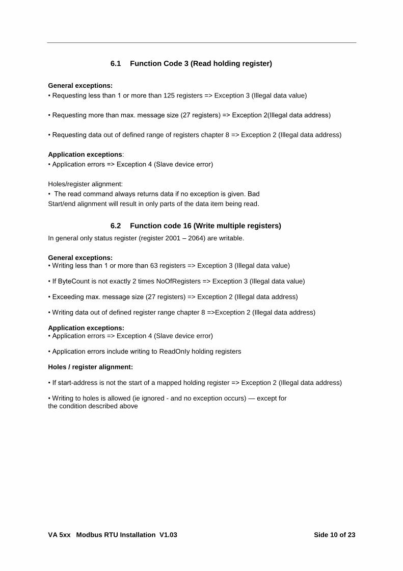
6.1 Function Code 3 (Read holding register)
General exceptions:
• Requesting less than 1 or more than 125 registers => Exception 3 (Illegal data value)
• Requesting more than max. message size (27 registers) => Exception 2(Illegal data address)
• Requesting data out of defined range of registers chapter 8 => Exception 2 (Illegal data address)
Application exceptions:
• Application errors => Exception 4 (Slave device error)
Holes/register alignment:
• The read command always returns data if no exception is given. Bad
Start/end alignment will result in only parts of the data item being read.
6.2 Function code 16 (Write multiple registers)
In general only status register (register 2001 – 2064) are writable.
General exceptions: • Writing less than 1 or more than 63 registers => Exception 3 (Illegal data value) • If ByteCount is not exactly 2 times NoOfRegisters => Exception 3 (Illegal data value) • Exceeding max. message size (27 registers) => Exception 2 (Illegal data address) • Writing data out of defined register range chapter 8 =>Exception 2 (Illegal data address) Application exceptions: • Application errors => Exception 4 (Slave device error) • Application errors include writing to ReadOnIy holding registers Holes / register alignment: • If start-address is not the start of a mapped holding register => Exception 2 (Illegal data address) • Writing to holes is allowed (ie ignored - and no exception occurs) — except for the condition described above

VA 5xx Modbus RTU Installation V1.03 Side 11 of 23
7 Modbus Holding Register
7.1 Basic Values Register (1…1000)
Modbus Register
Modbus Address
No.of Byte
Data Type Description Default Setting
Read Write
Unit /Comment
1 0 4 UInt32 Serial Number 0 R
3 2 4 UInt32
Software Version 0 R sprintf(str,"%u.%02u",hw>>16,hw&0xffff);
5 4 4 UInt32
Hardware Version 0 R sprintf(str,"%u.%02u",hw>>16,hw&0xffff);
7 6 4 UInt32
0 R
9 8 4 UInt32
Production Date 0 R Unix Time
11 10 4 UInt32
Calibration Date 0 R Unix Time
13 12 4 UInt32
Ordering Number 0 R
15 14 4 UInt32
RunTime 0 R Value in seconds
17 16 4 UInt32 0 R
19 18 4 UInt32 Atex Number 0 R
21 20 4 UInt32 Curve Version 0 R sprintf(str,"%u.%02u",hw>>16,hw&0xffff);
23 22 8 String Brand Name 0 R
27 26 4 UInt32 LockSettings 0 R
0 = NoLock, 1 = DiameterLock, 2 = CounterLock, 3 = RefConditionsLock
29 28 4 UInt32 OptionBoard 0 R
0 = no option 1 = 4-20mA 2 = Ethernet 3 = Mbus 4 = ProfiBus

VA 5xx Modbus RTU Installation V1.03 Side 12 of 23
7.2 Values register (1001….1500)
Modbus Register
Modbus Address
No.of Byte
Data Type Description Default Read Write
Unit /Comment
1001 1000 4 Float Flow as showed in Display R
1003 1002 4 UInt32 Total Counter bevore comma as showed in Display
R
1005 1004 4 Float Total Counter after comma as showed in Display
R
1007 1006 4 Float Velocity as showed in Display R
1009 1008 4 Float Gas Temperature as shoed in Display
R
1011 1010 4 Float Internal Temperature as showed in Display
R
1013 1012 4 Float Supply Voltage R
1015 1014 4 Float Max Speed (at Velocity Unit as showed in Display)
R
1017 1016 4 Float Max Flow (at Flow Unit as showed in Display)
R
1019 1018 4 Float Status of Sensor R
noError 0x0000 NotCalibrated 0x0001 LowVoltage 0x0002 TempError 0x0004 HeatError 0x0008 IntError 0x000a HeatNotCal 0x0020 AmbNotCal 0x0040 TmpOutofRange 0x0080 Direction 0x0100
1021 1020 4 Float Flow Min at Flow Unit in Display since Clear Min/Max
R
1023 1022 4 Float Flow Max at Flow Unit in Display since Clear Min/Max
R
1025 1024 4 Float Flow AV at Flow Unit in Display R AV over the Time from AV Time Setup 1 to 1440 minutes
1027 1026 4 Float Average Consumpton at Consumption Unit in Display
R Consumption over Time at AVTime Setup
1029 1028 4 Float Gas Temp Min at Temp. Unit in Display since Clear Min/Max
R
1031 1030 4 Float Gas Temp Max at Temp. Unit in Display since Clear Min/Max
R
1033 1032 4 Float Gas Temp AV at Temp. Unit in Display
R AV over the Time from AVTime Setup 1 to 1440 minutes
1035 1034 4 Float Velocity Min at Velocity Unit in Display since Clear Min/Max
R
1037 1036 4 Float Velocity Max at Velocity Unit in Display since Clear Min/Max
R
1039 1038 4 Float Velocity AV at Velocity Unit in Display
R AV over the Time from AVTime Setup 1 to 1440 minutes
VA 5xx Modbus RTU Installation V1.03 Side 13 of 23
Modbus Register
Modbus Address
No.of Byte
Data Type Description Default Read Write
Unit /Comment
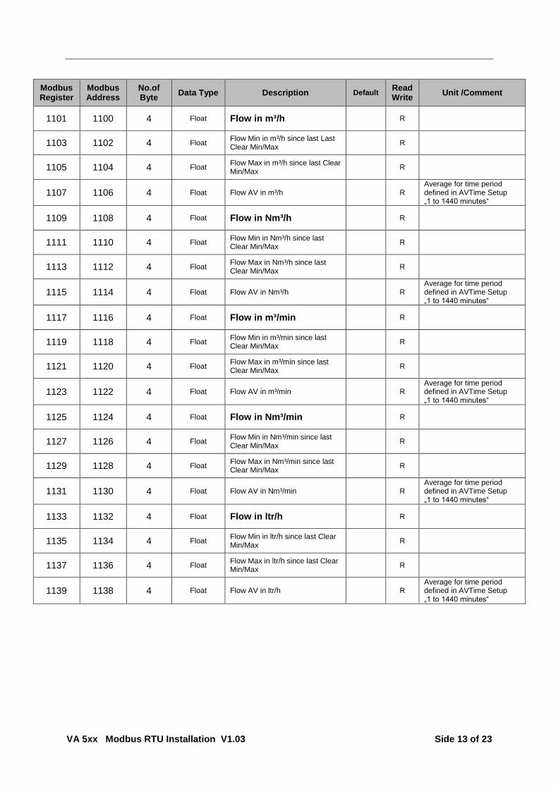
1101 1100 4 Float Flow in m³/h R
1103 1102 4 Float Flow Min in m³/h since last Last Clear Min/Max
R
1105 1104 4 Float Flow Max in m³/h since last Clear Min/Max
R
1107 1106 4 Float Flow AV in m³/h R Average for time period defined in AVTime Setup „1 to 1440 minutes“
1109 1108 4 Float Flow in Nm³/h R
1111 1110 4 Float Flow Min in Nm³/h since last Clear Min/Max
R
1113 1112 4 Float Flow Max in Nm³/h since last Clear Min/Max
R
1115 1114 4 Float Flow AV in Nm³/h R Average for time period defined in AVTime Setup „1 to 1440 minutes“
1117 1116 4 Float Flow in m³/min R
1119 1118 4 Float Flow Min in m³/min since last Clear Min/Max
R
1121 1120 4 Float Flow Max in m³/min since last Clear Min/Max
R
1123 1122 4 Float Flow AV in m³/min R Average for time period defined in AVTime Setup „1 to 1440 minutes“
1125 1124 4 Float Flow in Nm³/min R
1127 1126 4 Float Flow Min in Nm³/min since last Clear Min/Max
R
1129 1128 4 Float Flow Max in Nm³/min since last Clear Min/Max
R
1131 1130 4 Float Flow AV in Nm³/min R Average for time period defined in AVTime Setup „1 to 1440 minutes“
1133 1132 4 Float Flow in ltr/h R
1135 1134 4 Float Flow Min in ltr/h since last Clear Min/Max
R
1137 1136 4 Float Flow Max in ltr/h since last Clear Min/Max
R
1139 1138 4 Float Flow AV in ltr/h R Average for time period defined in AVTime Setup „1 to 1440 minutes“
VA 5xx Modbus RTU Installation V1.03 Side 14 of 23
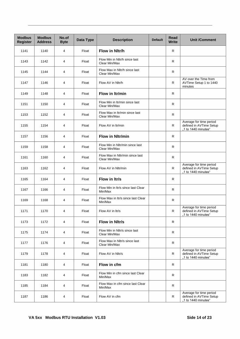
Modbus Register
Modbus Address
No.of Byte
Data Type Description Default Read Write
Unit /Comment
1141 1140 4 Float Flow in Nltr/h R
1143 1142 4 Float Flow Min in Nltr/h since last Clear Min/Max
R
1145 1144 4 Float Flow Max in Nltr/h since last Clear Min/Max
R
1147 1146 4 Float Flow AV in Nltr/h R AV over the Time from AVTime Setup 1 to 1440 minutes
1149 1148 4 Float Flow in ltr/min R
1151 1150 4 Float Flow Min in ltr/min since last Clear Min/Max
R
1153 1152 4 Float Flow Max in ltr/min since last Clear Min/Max
R
1155 1154 4 Float Flow AV in ltr/min R Average for time period defined in AVTime Setup „1 to 1440 minutes“
1157 1156 4 Float Flow in Nltr/min R
1159 1158 4 Float Flow Min in Nltr/min since last Clear Min/Max
R
1161 1160 4 Float Flow Max in Nltr/min since last Clear Min/Max
R
1163 1162 4 Float Flow AV in Nltr/min R Average for time period defined in AVTime Setup „1 to 1440 minutes“
1165 1164 4 Float Flow in ltr/s R
1167 1166 4 Float Flow Min in ltr/s since last Clear Min/Max
R
1169 1168 4 Float Flow Max in ltr/s since last Clear Min/Max
R
1171 1170 4 Float Flow AV in ltr/s R Average for time period defined in AVTime Setup „1 to 1440 minutes“
1173 1172 4 Float Flow in Nltr/s R
1175 1174 4 Float Flow Min in Nltr/s since last Clear Min/Max
R
1177 1176 4 Float Flow Max in Nltr/s since last Clear Min/Max
R
1179 1178 4 Float Flow AV in Nltr/s R Average for time period defined in AVTime Setup „1 to 1440 minutes“
1181 1180 4 Float Flow in cfm R
1183 1182 4 Float Flow Min in cfm since last Clear Min/Max
R
1185 1184 4 Float Flow Max in cfm since last Clear Min/Max
R
1187 1186 4 Float Flow AV in cfm R Average for time period defined in AVTime Setup „1 to 1440 minutes“

VA 5xx Modbus RTU Installation V1.03 Side 15 of 23
Modbus Register
Modbus Address
No.of Byte
Data Type Description Default Read Write
Unit /Comment
1189 1188 4 Float Flow in Ncfm R
1191 1190 4 Float Flow Min in Ncfm since last Clear Min/Max
R
1193 1192 4 Float Flow Max in Ncfm since last Clear Min/Max
R
1195 1194 4 Float Flow AV in Ncfm R Average for time period defined in AVTime Setup „1 to 1440 minutes“
1197 1196 4 Float Flow in kg/h R
1199 1198 4 Float Flow Min in kg/h since last Clear Min/Max
R
1201 1200 4 Float Flow Max in kg/h since last Clear Min/Max
R
1203 1202 4 Float Flow AV in kg/h R Average for time period defined in AVTime Setup „1 to 1440 minutes“
1205 1204 4 Float Flow in kg/min R
1207 1206 4 Float Flow Min in kg/min since last Clear Min/Max
R
1209 1208 4 Float Flow Max in kg/min since last Clear Min/Max
R
1211 1210 4 Float Flow AV in kg/min R Average for time period defined in AVTime Setup „1 to 1440 minutes“
1213 1212 4 Float Flow in kg/s R
1215 1214 4 Float Flow Min in kg/s since last Clear Min/Max
R
1217 1216 4 Float Flow Max in kg/s since last Clear Min/Max
R
1219 1218 4 Float Flow AV in kg/s R Average for time period defined in AVTime Setup „1 to 1440 minutes“
1221 1220 4 Float Flow in kW R
1223 1222 4 Float Flow Min in kW since last Clear Min/Max
R
1225 1224 4 Float Flow Max in kW since last Clear Min/Max
R
1227 1226 4 Float Flow AV in kW R Average for time period defined in AVTime Setup „1 to 1440 minutes“

VA 5xx Modbus RTU Installation V1.03 Side 16 of 23
Modbus Register
Modbus Address
No.of Byte
Data Type
Description Default Read Write
Unit /Comment
1269 1268 4 UInt32 Consumption m³ before comma x R
1271 1270 4 Float Consumption m² after comma x R
1273 1272 4 Float Consumption m³ AV x R Average for time period defined in AVTime Setup „1 to 1440 minutes“
1275 1274 4 UInt32 Consumption Nm³ before comma
x R
1277 1276 4 Float Consumption Nm³ after comma x R
1279 1278 4 Float Consumption Nm³ AV x R Average for time period defined in AVTime Setup „1 to 1440 minutes“
1281 1280 4 UInt32 Consumption ltr before comma x R
1283 1282 4 Float Consumption ltr after comma x R
1285 1284 4 Float Consumption ltr AV x R Average for time period defined in AVTime Setup „1 to 1440 minutes“
1287 1286 4 UInt32 Consumption Nltr before comma
x R
1289 1288 4 Float Consumption Nltr after comma x R
1291 1290 4 Float Consumption Nltr AV x R Average for time period defined in AVTime Setup „1 to 1440 minutes“
1293 1292 4 UInt32 Consumption cf before comma x R
1295 1294 4 Float Consumption cf after comma x R
1297 1296 4 Float Consumption cf AV x R Average for time period defined in AVTime Setup „1 to 1440 minutes“
1299 1298 4 UInt32 Consumption Ncf before comma x R
1301 1300 4 Float Consumption Ncf after comma x R
1303 1302 4 Float Consumption Ncf AV x R Average for time period defined in AVTime Setup „1 to 1440 minutes“
1305 1304 4 UInt32 Consumption kg before comma x R
1307 1306 4 Float Consumption kg after comma x R
1309 1308 4 Float Consumption kg AV x R Average for time period defined in AVTime Setup „1 to 1440 minutes“
1311 1310 4 UInt32 Consumption kWh before comma
x R
1313 1312 4 Float Consumption kWh after comma x R
1315 1314 4 Float Consumption kWh AV x R Average for time period defined in AVTime Setup „1 to 1440 minutes“

VA 5xx Modbus RTU Installation V1.03 Side 17 of 23
Modbus Register
Modbus Address
No.of Byte
Data Type Description Default
Read Write
Unit /Comment
1347 1346 4 Float Velocity m/s R
1349 1348 4 Float Velocity Min m/s since last Clear Min/Max
R
1351 1350 4 Float Velocity Max m/s since last Clear Min/Max
R
1353 1352 4 Float Velocity AV m/s R Average for time period defined in AVTime Setup „1 to 1440 minutes“
1355 1354 4 Float Velocity Nm/s R
1357 1356 4 Float Velocity Min Nm/s since last Clear Min/Max
R
1359 1358 4 Float Velocity Max Nm/s since last Clear Min/Max
R
1361 1360 4 Float Velocity AV Nm/s R Average for time period
defined in AVTime Setup „1 to 1440 minutes“
1363 1362 4 Float Velocity Ft/min R
1365 1364 4 Float Velocity Min Ft/min since last Clear Min/Max
R
1367 1366 4 Float Velocity Max Ft/min since last Clear Min/Max
R
1369 1368 4 Float Velocity AV Ft/min R Average for time period
defined in AVTime Setup „1 to 1440 minutes“
1371 1370 4 Float Velocity NFt/min R
1373 1372 4 Float Velocity Min NFt/min since last Clear Min/Max
R
1375 1374 4 Float Velocity Max NFt/min since last Clear Min/Max
R
1377 1376 4 Float Velocity AV NFt/min R Average for time period
defined in AVTime Setup „1 to 1440 minutes“
1419 1418 4 Float GasTemp °C R
1421 1420 4 Float GasTemp Min °C since Clear Min/Max
R
1423 1422 4 Float GasTemp Max °C since Clear Min/Max
R
1425 1424 4 Float GasTemp AV °C R Average for time period
defined in AVTime Setup „1 to 1440 minutes“
1427 1426 4 Float GasTemp °F R
1429 1428 4 Float GasTemp Min °F since Clear Min/Max
R
1431 1430 4 Float GasTemp Max °F since Clear Min/Max
R
1433 1432 4 Float GasTemp AV °F R Average for time period
defined in AVTime Setup „1 to 1440 minutes“

VA 5xx Modbus RTU Installation V1.03 Side 18 of 23
7.3 Device settings register
7.3.1 Modbus Settings (2001…2005)
Modbus Register
Modbus Address
No.of Byte
Data Type Description Default Setting
Read Write
Unit /Comment
2001 2000 2 UInt16 Modbus ID 1 R/W Modbus ID 1…247
2002 2001 2 UInt16 Baudrate 4 R/W
0 = 1200 1 = 2400 2 = 4800 3 = 9600 4 = 19200 5 = 38400
2003 2002 2 UInt16 Parity 1 R/W 0 = none 1 = even 2 = odd
2004 2003 2 UInt16 Number of Stopbits R/W 0 = 1 Stop Bit 1 = 2 Stop Bit
2005 2004 2 UInt16 Word Order 0xABCD R/W 0xABCD = Big Endian
0xCDAB = Middle Endian
7.3.2 Display Settings (2007…2009)
Modbus Register
Modbus Address
No.of Byte
Data Type Description Default Setting
Read Write
Unit /Comment
2007 2006 2 UInt16 Rotate Display(only VA550 / VA570)
0 R/W 0 = 0° 1 = 180°
2008 2007 2 UInt16 BackLight Brightness 80 R/W 30 to 100%
2009 2008 2 UInt16 Language 0 R/W 0 = English (at the moment only English supported)

VA 5xx Modbus RTU Installation V1.03 Side 19 of 23
7.3.3 Device Settings (2021…2063)
Modbus Register
Modbus Address
No.of Byte
Data Type Description
Default
Setting
Read Write
Unit /Comment
2021 2020 16 String Sensor Location "" R/W
2029 2028 4 Uint32 Calibrated GasType as index 0 R/W index to Get Gas Names as String at adr. 14000
2031 2030 4 Uint32 GasSubType (only available if Calibrated GasType is Air)
0 R/W
0 = Air 1 = CO2 2 = N2O 3 = N2 4 = O2 5 = NG 6 = AR 7 = He 8 = H2 9 = C3H8 10 = CH4
2033 2032 4 Uint32 Unit Length as index to Unit Table
64 (mm)
R/W
2035 2034 4 Uint32 Unit Flow as index to Unit Table
14 (m³/h)
R/W
2037 2036 4 Uint32 Unit Velocity as index to Unit Table
10 (m/s)
R/W
2039 2038 4 Uint32 Unit Consumption as index to Unit Table
24 (m³)
R/W
2041 2040 4 Uint32 Unit Temperature as index to Unit Table
1 (°C) R/W
2043 2042 4 Uint32 Unit Pressure as index to Unit Table
38 (mbar)
R/W
2045 2044 4 Float Diameter at the Unit programmed above
order R/W
2047 2046 4 Float Reference Temperature in Unit programmed above
20 R/W
2049 2048 4 Float Reference Pressure in Unit programmed above
1000 R/W
2051 2050 4 Float System Pressure in Unit programmed above
5000 R/W
2053 2052 4 Float Zero Point of Velocity in Unit programmed above
0 R/W
2055 2054 4 Float Min Velocity in Unit programmed above
0 R/W
2057 2056 4 Float LowPass Filter Time for Flow and Velocity in ms
100 R/W
2059 2058 4 Uint32 Average Time to Build Average (1 to 1440 minutes)
60 R/W
2061 2060 4 Float HeatRating for Flammable gases at 0°C / 1013.25mbar
0 R/W
2063 2062 4 Uint32 next Cal Date CalDate + 2 Years
R/W UnixTime

VA 5xx Modbus RTU Installation V1.03 Side 20 of 23
Modbus Register
Modbus Address
No.of Byte
Data Type Description
Default
Setting
Read Write
Unit /Comment
2081 2080 4 Float Relais Mode as index 1 R/W 0 = none 1 = Puls 2 = Alarm
2083 2082 4 Float Unit Puls from Unit Table U_m3 R/W
U_m3 U_ltr U_cf U_kg
2085 2084 4 Float Pulse Value (value where is generated a new puls)
1 R/W
2087 2086 4 Float Pulse Polarity 1 R/W 0 = neg 1 = pos
2089 2088 4 Float Unit Alarm from Unit Table U_GRAD_C
R/W
U_m_s U_m3_h U_ltr_s U_cfm U_kg_min U_kg_s U_GRAD_C U_GRAD_F
2091 2090 4 Float Alarm Value in Unit above 25 R/W
2093 2092 4 Float Alarm Hysteresis in Unit above 1 R/W
2095 2094 4 Float Alarm at overshot or undershot as index
1 R/W 0 = undershot 1 = overshot
2113 2112 4 Float Reset to Factory Defaults W send Serial Number to this adr. to set factory defaults
2115 2114 4 Float Consumption at programmed unit above
W if not locked, value to set consumption
2117 2116 4 Float Reset Min/Max Values W
2119 2118 4 Float Reset AV Values W
2121 2120 4 Float Temperature Correction Value at unit programmed above
R/W
Write the actual measured Temperature value to this register at read the offset to internal temperature is returned
VA 5xx Modbus RTU Installation V1.03 Side 21 of 23
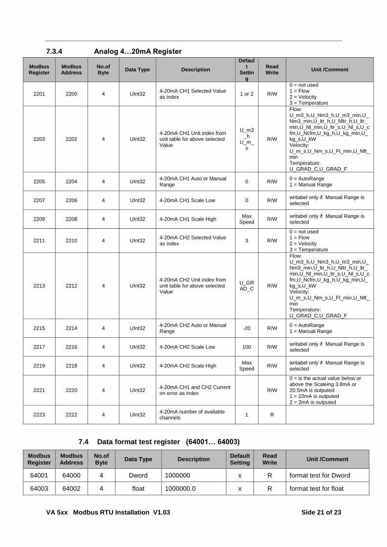
7.3.4 Analog 4…20mA Register
Modbus Register
Modbus Address
No.of Byte
Data Type Description
Default
Setting
Read Write
Unit /Comment
2201 2200 4 UInt32 4-20mA CH1 Selected Value as index
1 or 2 R/W
0 = not used 1 = Flow 2 = Velocity 3 = Temperature
2203 2202 4 UInt32 4-20mA CH1 Unit index from unit table for above selected Value
U_m3_h
U_m_s
R/W
Flow: U_m3_h,U_Nm3_h,U_m3_min,U_Nm3_min,U_ltr_h,U_Nltr_h,U_ltr_min,U_Nl_min,U_ltr_s,U_Nl_s,U_cfm,U_Ncfm,U_kg_h,U_kg_min,U_kg_s,U_kW Velocity: U_m_s,U_Nm_s,U_Ft_min,U_Nft_min Temperature: U_GRAD_C,U_GRAD_F
2205 2204 4 UInt32 4-20mA CH1 Auto or Manual Range
0 R/W 0 = AutoRange 1 = Manual Range
2207 2206 4 UInt32 4-20mA CH1 Scale Low 0 R/W writabel only if Manual Range is selected
2209 2208 4 UInt32 4-20mA CH1 Scale High Max
Speed R/W
writabel only if Manual Range is selected
2211 2210 4 UInt32 4-20mA CH2 Selected Value as index
3 R/W
0 = not used 1 = Flow 2 = Velocity 3 = Temperature
2213 2212 4 UInt32 4-20mA CH2 Unit index from unit table for above selected Value
U_GRAD_C
R/W
Flow: U_m3_h,U_Nm3_h,U_m3_min,U_Nm3_min,U_ltr_h,U_Nltr_h,U_ltr_min,U_Nl_min,U_ltr_s,U_Nl_s,U_cfm,U_Ncfm,U_kg_h,U_kg_min,U_kg_s,U_kW Velocity: U_m_s,U_Nm_s,U_Ft_min,U_Nft_min Temperature: U_GRAD_C,U_GRAD_F
2215 2214 4 UInt32 4-20mA CH2 Auto or Manual Range
-20 R/W 0 = AutoRange 1 = Manual Range
2217 2216 4 UInt32 4-20mA CH2 Scale Low 100 R/W writabel only if Manual Range is selected
2219 2218 4 UInt32 4-20mA CH2 Scale High Max
Speed R/W
writabel only if Manual Range is selected
2221 2220 4 UInt32 4-20mA CH1 and CH2 Current on error as index
R/W
0 = is the actual value below or above the Scaleing 3.8mA or 20.5mA is outputed 1 = 22mA is outputed 2 = 2mA is outputed
2223 2222 4 UInt32 4-20mA number of available channels
1 R
7.4 Data format test register (64001… 64003)
Modbus Register
Modbus Address
No.of Byte
Data Type Description Default Setting
Read Write
Unit /Comment
64001 64000 4 Dword 1000000 x R format test for Dword
64003 64002 4 float 1000000.0 x R format test for float

VA 5xx Modbus RTU Installation V1.03 Side 22 of 23
8 Appendix
8.1 APPENDIX A - Exception codes
The FA 5xx Modbus uses the following exception codes when responding to the master
Exception Code Exception name
0x01 Illegal function
0x02 Illegal data address
0x03 Illegal data value
0x04 Slave device failure
0x05 Acknowledge
0x06 Slave device busy

VA 5xx Modbus RTU Installation V1.03 Side 23 of 23
9 Change history
Author Date Version Changes
KH.Frank 23.08.2015 1.00 First issue
KH.Frank 06.11.2015 1.01 Correction Data type „datatype „consumption before comma“
KH.Frank 03.05.2016 1.02 Correction VA500/VA520 connection diagram (Common Pin) Correction text
KH.Frank 15.06.2016 1.03 Adding Bias