MOD Architectural Framework The MODAF Meta-Model · "cheat-sheets" which show the chain of elements...
109
IA/13/02-M3 1 of 109 MINISTRY OF DEFENCE MOD Architectural Framework The MODAF Meta-Model Model Version 1.0 Document Version 1.0 11 April 2006 Prepared by:- (Editor) Dr Peter Bryant, IA8Con2 (LogicaCMG) (Lead Modeller) Dr Ian Bailey, IA8bCon5 (Cornwell) Approved by:- MODAF Technical Working Group CROWN COPYRIGHT 2006. THIS DOCUMENT IS THE PROPERTY OF HER BRITANNIC MAJESTY’S GOVERNMENT. This material (other than the Royal Arms and departmental or agency logos) may be reproduced free of charge in any format or medium provided it is reproduced accurately and not used in a misleading context. Where this material is being republished or copied to others, the source of the material must be identified and the copyright status acknowledged. For further information on Crown Copyright policy and licensing arrangements, see the guidance featured on the HMSO website http://www.opsi.gov.uk
Transcript of MOD Architectural Framework The MODAF Meta-Model · "cheat-sheets" which show the chain of elements...

IA/13/02-M3
1 of 109
MINISTRY OF DEFENCE
MOD Architectural Framework The MODAF Meta-Model
Model Version 1.0
Document Version 1.0
11 April 2006
Prepared by:- (Editor) Dr Peter Bryant, IA8Con2 (LogicaCMG) (Lead Modeller) Dr Ian Bailey, IA8bCon5 (Cornwell) Approved by:- MODAF Technical Working Group
CROWN COPYRIGHT 2006. THIS DOCUMENT IS THE PROPERTY OF HER BRITANNIC MAJESTY’S GOVERNMENT. This material (other than the Royal Arms and departmental or agency logos) may be reproduced free of charge in any format or medium provided it is reproduced accurately and not used in a misleading context. Where this material is being republished or copied to others, the source of the material must be identified and the copyright status acknowledged. For further information on Crown Copyright policy and licensing arrangements, see the guidance featured on the HMSO website http://www.opsi.gov.uk
IA/13/02-M3
2 of 109
RECORD OF CHANGES
This page will be updated and re-issued with each amendment. It provides an authorisation for the amendment and a checklist to the current amendment number.
Issue No. Date Revision Details
Draft 0.1
15 February 2005 First draft for internal review
Draft 0.2
17 March 2005 Second draft incorporating XMI 1.x examples and usage documentation
Draft 0.3 23 March 2005 Third draft – revising the introduction, and removing comments.
Draft 0.4 31 March 2005 Draft for internal review – incorporating XMI 2.1 examples
Draft 0.5 7 September 2005 Documentation of final draft model (v0.95) for implementation testing.
Draft 0.6 13 March 2006 Document re-structured and expanded. Number changed.
Draft 0.7 17 March 2006 Incorporated comments from Ian Bailey
Draft 0.8 27 March 2006 View by view descriptions revised in line with model changes
Draft 0.9 3 April 2006 Document revised with revised model (v0.99)
Issue 1.0 11 April 2006 First baseline release
IA/13/02-M3
3 of 109
FOREWORD
This document represents the first baseline release of the MODAF Meta-Model (M3). The document complements the web presentation of M3 available at www.modaf.com. The M3:
specifies an interchange standard for MODAF architectures
provides a logical description of MODAF by defining the elements that constitute the various architectural views and how those elements are related
provides a ‘language’ for MODAF-based architectures.
This baseline release of M3 does much more to integrate the strategic and acquisition views with the rest of the architectural framework. To help users and vendors to understand the model, we have provided high-level overview diagrams for each MODAF viewpoint and two "cheat-sheets" which show the chain of elements needed to represent capability deployment and capability delivery.
During development of this baseline there have been several changes that are significant for MODAF. These changes will be the subject of future review of the current baseline documentation set, i.e. the MODAF Technical Handbook, which defines the MODAF views, and the MODAF Deskbooks, which provide guidance on the employment of MODAF by particular MOD Communities of Interest.
The core of M3, covering the MODAF views, is stable at v1.0 and will not change in the near future unless serious issues are discovered as vendors begin implementation. There are also some "straw man" model elements included in this release, covering Effects Based Operations (EBO) and Service Oriented Architectures (SOA). As both these disciplines are relatively new, the ideas are yet to be consolidated and agreed. Hence, these parts of the M3 should be treated as experimental - vendors are free to implement them, but should be prepared for changes and extensions in the near future.
IA/13/02-M3
4 of 109
Table of Contents
Table of Contents....................................................................................................................................4 1 Introduction ......................................................................................................................................7
1.1 Roles of M3 in MODAF.............................................................................................................7 1.1.1 Model interchange standard..............................................................................................7 1.1.2 Logical description of MODAF...........................................................................................8 1.1.3 A language for MODAF-based architectures ....................................................................8
1.2 Technical Description of the M3 ...............................................................................................8 1.3 Audience Needs .......................................................................................................................9 1.4 Structure of This Document......................................................................................................9 1.5 References ...............................................................................................................................9 1.6 M3 Ownership and Change Process......................................................................................10 1.7 M3 Model Change History ......................................................................................................11
2 High Level Structure of M3 ............................................................................................................12 2.1 Viewpoints ..............................................................................................................................12 2.2 Simplified Presentation of M3.................................................................................................12
2.2.1 Strategic Viewpoint..........................................................................................................12 2.2.2 Operational Viewpoint .....................................................................................................14 2.2.3 Systems Viewpoint ..........................................................................................................15 2.2.4 Technical Viewpoint ........................................................................................................16 2.2.5 Acquisition Viewpoint ......................................................................................................17
2.3 Viewpoint Linkages.................................................................................................................19 2.4 High Level Presentation of Key M3 Elements Against Views ................................................20
3 M3 Specification.............................................................................................................................21 3.1 Introduction to the M3.............................................................................................................21 3.2 Reading M3 ............................................................................................................................22 3.3 M3 Presented View-by-View ..................................................................................................24
3.3.1 AV-1 MODAF Meta-Model Support.................................................................................24 3.3.2 AV-2 MODAF Meta-Model Support.................................................................................26 3.3.3 MODAF Meta-Model Support For Effectivity Constraints ...............................................28 3.3.4 MODAF Meta-Model Support For Measurable Properties..............................................29 3.3.5 MODAF Meta-Model Support For Requirements............................................................30 3.3.6 StV-1 MODAF Meta-Model Support................................................................................31 3.3.7 StV-2 MODAF Meta-Model Support................................................................................33 3.3.8 StV-3 MODAF Meta-Model Support................................................................................34 3.3.9 StV-4 MODAF Meta-Model Support................................................................................36 3.3.10 StV-5 MODAF Meta-Model Support................................................................................37 3.3.11 StV-6 MODAF Meta-Model Support................................................................................39 3.3.12 OV-1 MODAF Meta-Model Support ................................................................................41 3.3.13 OV-2 MODAF Meta-Model Support ................................................................................43

IA/13/02-M3
5 of 109
3.3.14 OV-3 MODAF Meta-Model Support ................................................................................45 3.3.15 OV-4 MODAF Meta-Model Support ................................................................................46 3.3.16 OV-5 MODAF Meta-Model Support ................................................................................48 3.3.17 OV-6a MODAF Meta-Model Support ..............................................................................50 3.3.18 OV-6b MODAF Meta-Model Support ..............................................................................51 3.3.19 OV-6c MODAF Meta-Model Support ..............................................................................52 3.3.20 OV-7 MODAF Meta-Model Support ................................................................................53 3.3.21 SV-1 MODAF Meta-Model Support.................................................................................54 3.3.22 SV-2a MODAF Meta-Model Support...............................................................................56 3.3.23 SV-2b MODAF Meta-Model Support...............................................................................57 3.3.24 SV-2c MODAF Meta-Model Support ...............................................................................58 3.3.25 SV-3 MODAF Meta-Model Support.................................................................................59 3.3.26 SV-4 MODAF Meta-Model Support.................................................................................61 3.3.27 SV-5 MODAF Meta-Model Support.................................................................................63 3.3.28 SV-6 MODAF Meta-Model Support.................................................................................64 3.3.29 SV-7 MODAF Meta-Model Support.................................................................................65 3.3.30 SV-8 MODAF Meta-Model Support.................................................................................66 3.3.31 SV-9 MODAF Meta-Model Support.................................................................................68 3.3.32 SV-10a MODAF Meta-Model Support.............................................................................69 3.3.33 SV-10b MODAF Meta-Model Support.............................................................................70 3.3.34 SV-10c MODAF Meta-Model Support .............................................................................71 3.3.35 SV-11 MODAF Meta-Model Support...............................................................................72 3.3.36 TV-1 & TV-2 MODAF Meta-Model Support.....................................................................73 3.3.37 AcV-1 MODAF Meta-Model Support ...............................................................................74 3.3.38 AcV-2 MODAF Meta-Model Support ...............................................................................75
3.4 Proposed Extensions to Core M3...........................................................................................77 3.4.1 Proposed MODAF Meta-Model Support for Effects Based Operations..........................77 3.4.2 Proposed MODAF Meta-Model Support for SOA Services ............................................78
4 Definition of M3 Elements..............................................................................................................79 4.1 M3 Elements (Core M3) .........................................................................................................79 4.2 M3 Elements (Proposed Extensions to Core M3) ..................................................................95
5 Comparison with DoDAF ...............................................................................................................96 5.1 Strategic Viewpoint .................................................................................................................96 5.2 Acquisition Viewpoint..............................................................................................................97 5.3 SOA Services and Effects Based Operations ........................................................................97 5.4 Model Concepts......................................................................................................................97 5.5 Specific Views.........................................................................................................................98 5.6 Role of UML............................................................................................................................98
6 Changes to MODAF.....................................................................................................................100 6.1 Recent Changes to M3.........................................................................................................100

IA/13/02-M3
6 of 109
6.1.1 Further integration of the Strategic Viewpoint ...............................................................100 6.1.2 Nodes and Capability Configurations............................................................................101 6.1.3 Incorporation of Physical Assets into the Operational Viewpoint..................................101 6.1.4 Introduction of System Ports into the System Viewpoint...............................................101 6.1.5 Enrichment of system data linkages .............................................................................101 6.1.6 Further integration of the Acquisition Viewpoint............................................................102 6.1.7 Proposed incorporation of services for SOA.................................................................102
6.2 Drivers for Future Change ....................................................................................................102 6.2.1 Use of MODAF and M3 v1 ............................................................................................103 6.2.2 Evolution of MODAF documentation.............................................................................103 6.2.3 Development of service views.......................................................................................103 6.2.4 SysML............................................................................................................................103 6.2.5 BPMN ............................................................................................................................104 6.2.6 International developments ...........................................................................................104
6.3 Change Cycle .......................................................................................................................104 Appendix A: M3 Change Log ..............................................................................................................105
A.1 Changes between v0.95 and v0.98......................................................................................105 A.2 Changes between v0.98 and v1.0 ........................................................................................108

IA/13/02-M3
7 of 109
1 Introduction
MODAF (the MOD Architectural Framework) provides a specification of how to represent an integrated model of an enterprise, from the operational / business aspects to the organisations and systems that provide capability, with appropriate standards and programmatic aspects – i.e. an enterprise architectural framework. It assists in managing complexity by providing a logical, standardised way to organise, present and integrate models of the enterprise. By covering both the operational and technical aspects across the enterprise, MODAF-compliant Architectures enable all communities of interest to gain the essential common understanding that will be required to deliver the benefits to be derived from Network Enabled Capability (NEC). MODAF is defined in the Technical Handbook [1].
This document is the first baseline for the meta-model for the MOD Architectural Framework (MODAF).
1.1 Roles of M3 in MODAF
The roles of the MODAF Meta-Model are to:
Specify an interchange standard for MODAF architectures
Provide a logical description of MODAF by defining the elements that constitute the various architectural views and how those elements are related
Provide a ‘language’ for MODAF-based architectures.
These roles are explained in the following sub-sections.
1.1.1 Model interchange standard
One purpose of the MODAF Meta-Model (M3) is to specify the data exchange format for MODAF architectures. The chosen file format is the OMG’s XMI specification (v2.1)1. In order to make maximum re-use of the XMI interfaces that tool vendors may already have, the MODAF Meta-Model is defined as an extension of the UML 2.0 Meta-Model - UML is the Unified Modelling Language2.
In UML terminology:
the M3 defines an abstract syntax for a UML profile3
each element defined in the M3 specifies a UML stereotype4.
The M3 does not provide the concrete syntax (the visual representation of the stereotypes that would appear in a UML diagram) because MOD has not chosen UML as the only modelling approach for MODAF products.
An abstract syntax is sufficient to specify the XMI usage and therefore to act as the model interchange standard for MODAF.
1 XMI2.1 was ratified in September 2005 [5]. 2 UML is an industry-led open standard which is recognised as the de facto modelling language for architecture modelling in support of software development. It is also becoming more widely used outside of the software world, for areas such as business process modelling and systems engineering. The implications for MODAF of the emergence of SysML, the systems engineering extension of UML, are explored in Section 6. 3 A UML profile specifies a way of using UML for a specialist purpose. A profile consists of formal rules about how the UML modelling elements can be used, and a set of stereotypes suitable for the purpose of the profile. 4 UML stereotypes are a way of extending existing UML modelling elements for a specific purpose, e.g. a model element called ‘System’ may be defined that extends the based “class” concept in UML.
IA/13/02-M3
8 of 109
1.1.2 Logical description of MODAF
The M3 is the information model for MODAF defining the structure of the underlying architecture information that is presented in views. The M3 describes the complete set of architectural elements and their relationships, within and across views and viewpoints. The intention is that architectural elements defined for use in one view can be re-used in a second. [1]
One driver for regarding the M3 in this way is the need to provide a firm foundation for both tool certification and the assessment of compliance of MODAF products. The M3 provides semantic and syntactic rigour for MODAF.
It is important to stress that the M3 is not a conceptual data model - the intent is to capture the architectural elements and the relationships between them. A mapping to the MODAF ontology is the subject of parallel work.
1.1.3 A language for MODAF-based architectures
The M3 provides a ‘language’ for MODAF-based architectures by provide semantic definitions of the elements that can be used in a MODAF-compliant architecture and the allowed relationships between them. The M3 defines both the semantics and syntax for MODAF modelling. It demonstrates the conceptual integrity at the heart of MODAF (through unambiguous definition of architectural elements and their relationships backed up by business justification through links to the MODAF ontology).
The practical realisation of this ‘language’ for MODAF will typically be underpinned by a formal modelling language. Use of a modelling language such as UML brings discipline and precision to architecture modelling, ensuring that anyone who understands the language can correctly interpret the information provided by the architecture model. Use of a particular modelling language in conjunction with this specification will enable the M3 to be realised as a concrete syntax.
1.2 Technical Description of the M3
Each MODAF view defined in the Technical Handbook [1] has a specific diagram showing an extract from the M3 that is relevant to the data concepts associated with that view. As a result of the development of this initial baseline of the M3, the Technical Handbook will need to be revised.
In this document the MODAF stereotype definitions are specified as extensions of the base UML meta-classes. Each M3 diagram has a short introductory text, providing further explanation of the key concepts behind that portion of the model. Each stereotype has a definition text and significant attributes are also documented.
The M3 is:
• a single, contiguous model with elements that are intended to be used and re-used across the MODAF products
• an extension of the UML 2.0 Meta-Model
• an abstract syntax for a UML 2.0 profile
• intended to cover all architectural elements associated with a MODAF view.
The MODAF Meta-Model (M3) documented in this publication is also provided as a set of navigable web pages on the MODAF website [2]. This document provides additional descriptive material by providing a textual description of the model and its intended use.
IA/13/02-M3
9 of 109
1.3 Audience Needs
This document is primarily aimed at two sections of the MODAF community:
Advanced modellers
Tool support implementation teams.
Starting from a view definition, a MODAF product is developed by creating architectural elements that are model data objects ‘stereotyped’ by reference to the relevant extract from the M3. The M3 specifies the syntactic rules that allow conformance of a MODAF product to be judged. The architectural elements can be presented through view products (for user accessibility) or exchanged (using XMI) for re-use. Selected architectural elements may be related to unique taxonomic elements that provide the semantic definitions of those elements. Advanced modellers need to understand the stereotyping of architectural elements and their allowable connections. They need to understand the semantics of stereotyped architectural elements and how these relate to higher level MODAF concepts (e.g. what a node is and in what viewpoints one would expects nodes to be modelled) and, ideally in what way these might differ from DoDAF5. Advanced modellers will benefit from the simplified presentation of M3 provided in Section 2.
Architectural tool implementers require a precise specification of the syntax of stereotyped architectural elements together with the link to UML meta-classes allowing correct implementation of XMI interfaces6.
1.4 Structure of This Document
This document is structured as follows. Section 1: Introduction Describes the context for M3 and the technical background
Section 2: High Level Structure of M3 Provides a high level view of M3
Section 3: M3 Specification Provides a view-by-view specification of M3
Section 4: M3 Element Definitions Defines the M3 elements
Section 5: Comparison with DoDAF Highlights essential differences from DoDAF
Section 6: Changes to MODAF Describes recent changes of M3 and anticipated drivers for future changes
Appendix A M3 change log
1.5 References
1. “MOD Architectural Framework Technical Handbook”, version 1, 31st August 2005.
2. M3 Model available on public internet via www.modaf.com/m3.
3. UML 2.0 Superstructure, OMG specification, http://www.omg.org/technology/ documents/formal/uml.htm.
5 They also need to understand how to use the MODAF Taxonomy in order to construct models – not addressed in this document. 6 They also need to understand how their tools will link to the MODAF taxonomy – not addressed in this document.
IA/13/02-M3
10 of 109
4. UML 2.0 Infrastructure, OMG specification, http://www.omg.org/technology/ documents/formal/uml.htm.
5. XMI 2.1 Specification, OMG specification, http://www.omg.org/technology/ documents/ formal/xmi.htm.
6. Meeting notes of the 4th MODAF Technical Working Group held on 17th February 2006.
7. “MODAF Meta-Model Release Policy”, note released on MODAF website on 28th February 2006.
8. “US Department of Defense Architecture Framework”, Version 1.0, 15 January 2003, DoD Architecture Framework Working Group.
9. “IEEE Recommended Practice for Architectural Description”, IEEE Std 1471-2000, approved 21st September 2000.
10. “System Modeling Language (SysML) draft specification”, version 0.99, OMG document ad/2006-02-01, SysML Merge Team.
11. “Business Process Modelling Notation”, http://www.bpmi.org/.
12. “XMI, UML and MODAF”, version 1, IA/02/16-ERMcm03, 14th February 2005.
13. OMG Request For Proposal (RFP) – UML Profile for MODAF/DODAF (UPDM), 16th September 2005, http://syseng.omg.org/UPDM.htm.
1.6 M3 Ownership and Change Process
This initial baseline was created by the MODAF Enablers team under contract to the Integration Authority (IA).
The M3 is currently being maintained by the IA on behalf of DG Info.
The following change process is in place:
feedback on the M3 is received by the M3 maintenance team, the preferred mechanism being via on-line feedback forms provided on the MODAF website
the maintenance team assesses the impact of the proposed change and, if necessary, formalises the change as a specific change proposal
if the change only affects the M3, then ratification of the change is required from the MODAF Technical Group before implementation; for changes which would have a wider impact (e.g. on MODAF documentation or the concept of use), ratification may also be required from the MODAF User Group
once ratified, the maintenance team updates the master copy of the M3 documentation (and supporting UML model as required)
release of the updated documentation will be timed to ensure synchronicity is maintained with the wider MODAF documentation set
the M3 documentation and UML model have separate version numbers; updates to the UML model (or notifications of future updates) may be posted on the MODAF website at a suitable point.

IA/13/02-M3
11 of 109
1.7 M3 Model Change History
A complete change log is provided in this document as Appendix A.
Following direction from the MODAF Technical Working Group [6], the scope of changes to the M3 from v0.95 (published at the same time as the initial MODAF baseline) has not been constrained by the need to retain consistency with the existing MODAF documentation (i.e. the current v1 Handbook and COI Deskbooks). Now that an unambiguous definition of MODAF has been developed by baselining the M3, MOD intends to update the MODAF documentation in due course [7].
The major change proposals are documented in Section 5. These are changes to the core model as a result of feedback on the existing version from MOD and Industry Stakeholders. The current version of the M3 has also incorporated a proposal for modelling services based on initial investigations into incorporating Service Oriented Architectures (SOA) into defence architectures7.
The M3 release policy [7] recognises the importance of a period of stability to fully understand the practical implications of this first baseline release of the M3, and to allow realignment with the MODAF documentation. In addition, a MODAF tool certification process is to be developed that is dependent on having a stable M3. Having a documented certification process will allow MOD to update the MOD policy on MODAF compliant tools and allow tools to stand on their own merits. It is therefore MOD’s intention that the next review of the core M3 will be in 12 months following the date of this baseline.
7 At the time of publication, the meta-model proposal is in advance of development of associated views.
Date Version Notes
7th Sep 05
16th Mar 06
21st Apr 06
0.95
0.98
1.0
Technically complete draft for publication alongside the initial MODAF baseline
Extended M3 with revised documentation
First full baseline of M3
IA/13/02-M3
12 of 109
2 High Level Structure of M3
2.1 Viewpoints
Within an architectural framework, a viewpoint corresponds to the perspective of a set of architecture stakeholders. Viewpoints are used to group individual framework views into coherent sets.
MODAF uses the following viewpoints:
Strategic (6 views)
Operational (7 views)
Systems (11 views)
Technical (2 views)
Acquisition (2 views).
In addition, the ‘All Views’ Viewpoint is used to group together two MODAF views that are relevant to all architecture stakeholders. As explained in Section 4.1, the M3 is structured similarly.
2.2 Simplified Presentation of M3
The simplified presentation of the M3 presented in this section is intended to provide a high-level coherent view of the whole meta-model, focusing on the key concepts. It was introduced as a result of stakeholder feedback on the v0.95 model.
The key M3 elements are depicted on these simplified views. They are colour coded in accordance with the MODAF Viewpoints (using the colour scheme introduced in the Technical Handbook).
2.2.1 Strategic Viewpoint
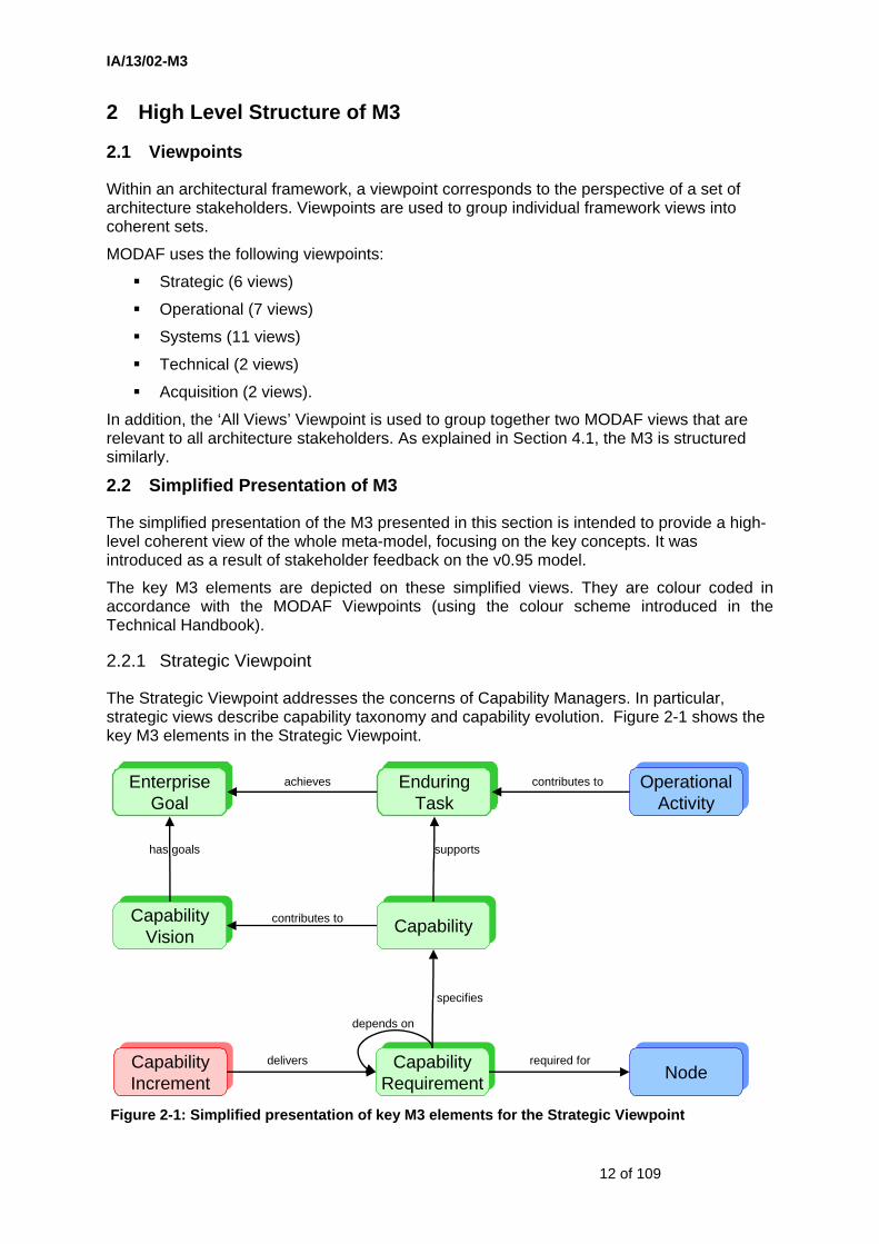
The Strategic Viewpoint addresses the concerns of Capability Managers. In particular, strategic views describe capability taxonomy and capability evolution. Figure 2-1 shows the key M3 elements in the Strategic Viewpoint.
Figure 2-1: Simplified presentation of key M3 elements for the Strategic Viewpoint
CapabilityCapability
CapabilityRequirementCapability
Requirement
CapabilityVision
CapabilityVision
OperationalActivity
OperationalActivity
specifies
supports
EnduringTask
EnduringTask
achieves contributes toEnterpriseGoal
EnterpriseGoal
has goals
contributes to
NodeNoderequired for
depends on
CapabilityIncrement
CapabilityIncrement
delivers
IA/13/02-M3
13 of 109
An Enterprise has a time-bounded Capability Vision which encompasses transformational Enterprise Goals. The Enterprise Goals may be achieved through a set of Enduring Tasks (which might relate to Defence Military Tasks or Joint Essential Tasks) that are supported by a high-level set of capability-enabled Operational Activities.
The Capability Vision gives rise to Capabilities that are intended to support the Capability Vision. These Capabilities may form a taxonomic hierarchy and have inter-dependencies (specialisation and decomposition need to be distinguished). A number of Capability Requirements may be specified for a given Capability (e.g. there may be different Capability Requirements associated with different environments or different epochs). Each Capability requirement specifies a set of metrics which define the performance parameters for the related capability in the specified epoch.
Fulfilment of the capability requirements at a given time enables a particular set of Operational Activities to be carried out so that, over time, the Enterprise Goals associated with the Capability Vision may be fulfilled.
Capability requirements are fulfilled by Capability Configurations (combinations of people, information, equipment and physical assets) created through acquisition activities - that yield Capability Increments - according to the Lines of Development.
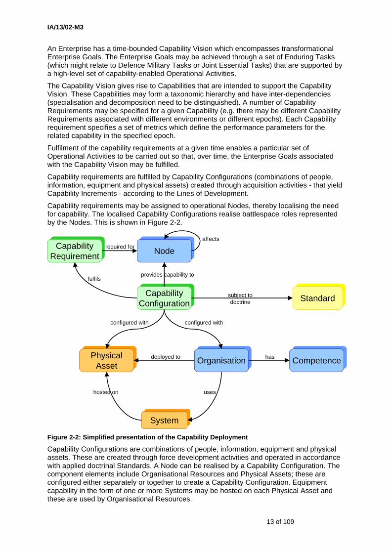
Capability requirements may be assigned to operational Nodes, thereby localising the need for capability. The localised Capability Configurations realise battlespace roles represented by the Nodes. This is shown in Figure 2-2.
Figure 2-2: Simplified presentation of the Capability Deployment
Capability Configurations are combinations of people, information, equipment and physical assets. These are created through force development activities and operated in accordance with applied doctrinal Standards. A Node can be realised by a Capability Configuration. The component elements include Organisational Resources and Physical Assets; these are configured either separately or together to create a Capability Configuration. Equipment capability in the form of one or more Systems may be hosted on each Physical Asset and these are used by Organisational Resources.
CapabilityConfigurationCapability
Configuration
PhysicalAsset
PhysicalAsset
OrganisationOrganisation
configured with
StandardStandardsubject todoctrine
hosted on
SystemSystem
uses
CompetenceCompetencehas
configured with
deployed to
NodeNode
provides capability to
CapabilityRequirementCapability
Requirementrequired for
fulfils
affects
IA/13/02-M3
14 of 109
In the M3, Organisational Resources include Organisations and Post Types (filled or unfilled) – these may represent required or actual organisations and posts. An Organisational Resource has associated with it one or more competences (either actual or required). Projects including training activities may create actual Competences.
Organisational Resources conduct Operational Activities by means of which Information is generated. Similarly Systems generate Data. Therefore inclusion of Information and Data is implicit in the derivation of a Capability Configuration8.
2.2.2 Operational Viewpoint
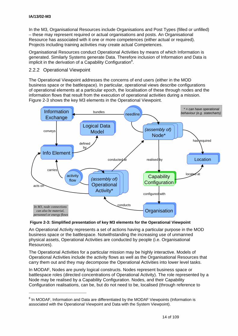
The Operational Viewpoint addresses the concerns of end users (either in the MOD business space or the battlespace). In particular, operational views describe configurations of operational elements at a particular epoch, the localisation of these through nodes and the information flows that result from the execution of operational activities during a mission. Figure 2-3 shows the key M3 elements in the Operational Viewpoint.
Figure 2-3: Simplified presentation of key M3 elements for the Operational Viewpoint
An Operational Activity represents a set of actions having a particular purpose in the MOD business space or the battlespace. Notwithstanding the increasing use of unmanned physical assets, Operational Activities are conducted by people (i.e. Organisational Resources).
The Operational Activities for a particular mission may be highly interactive. Models of Operational Activities include the activity flows as well as the Organisational Resources that carry them out and they may decompose the Operational Activities into lower level tasks.
In MODAF, Nodes are purely logical constructs. Nodes represent business space or battlespace roles (directed concentrations of Operational Activity). The role represented by a Node may be realised by a Capability Configuration. Nodes, and their Capability Configuration realisations, can be, but do not need to be, localised (through reference to
8 In MODAF, Information and Data are differentiated by the MODAF Viewpoints (Information is associated with the Operational Viewpoint and Data with the System Viewpoint).
(assembly of)Node*
(assembly of)Node*
realised by
InformationExchange
InformationExchange
bundles
(assembly of)Operational
Activity*
(assembly of)Operational
Activity*
conducts
carries
* = can have operationalbehaviour (e.g. statecharts) needline
conducted at
conveys
Logical Data Model
Logical Data Model
defined by
LocationLocation
located at
Info ElementInfo Element
has required
CapabilityConfigurationCapability
Configuration
OrganisationOrganisation
configured with
activityflow
acts on
In M3, node connections can also be material,
personnel or energy flows

IA/13/02-M3
15 of 109
either a general or specific Location). Models of Nodes (or the Operational Activities themselves) may address operational behaviour, e.g. through activity sequences. Simple constraints and more complex rules that constrain operational behaviour (i.e. responses to operational events) may also be modelled. Nodes may be composite structures (so that one Node may have several sub-Nodes). Connections between Nodes may refer to information, material or energy flows. An information-based connection (a Needline) between two Nodes is associated with a bundle of Information Exchanges (actual or required) which convey information elements that are carried between the Operational Activities that are conducted at the two Nodes. In this way, localised collaboration requirements can be modelled. Finally, the Information Elements that are conveyed by Information Exchanges may be defined in a Logical Data Model which captures the operational informatic entities and their relationships.
However, the Operational Viewpoint also enables modelling of flows of material, personnel or energy, as well as information (see Section 5.4). This version of the M3 includes a proposed model of Effects (which includes relationships between Nodes such as NodeAffectsNode).
2.2.3 Systems Viewpoint
The Systems Viewpoint addresses the concerns of procurers and developers of equipment capability, including system architects. A System may be an entire stand-alone equipment capability, a Physical Asset, a software application, a system interface, an information capability or a network element. Figure 2-4 shows the key M3 elements in the System Viewpoint.
Figure 2-4: Simplified presentation of key M3 elements for the System Viewpoint
Models of equipment capability often span several levels of abstraction. Systems may be decomposed into sub-Systems and sub-Systems into System components, for instance. Systems are defined by the System Functions that they provide (and these may be modelled through functional decompositions that reflect the System decomposition). System Functions support Operational Activities (i.e. there is a functional trace relationship between System Functions and Operational Activities).
System Port*System Port*
(assembly of)System*
(assembly of)System*
* = can have systembehaviour (e.g. statecharts)
provides
hosted on
part of
DataExchange
DataExchange System
Function*(break down)
System Function*
(break down)
realised by
end for
OperationalActivity
OperationalActivity
supports
systemconnector
Data ElementData Element
conveys
carries
acts on
functionflow
functionflow
PhysicalAsset
PhysicalAsset
IA/13/02-M3
16 of 109
When modelling information rich equipment capabilities, it is sometimes essential to be able to model the fact that a System Function acts on a particular set of Data Elements. Models of Systems may address behaviour, e.g. through models of state transitions or functional sequencing. Simple constraints and more complex rules that constrain system behaviour (i.e. system responses to events) may also be modelled.
Interactions between the Functions of different Systems are the origin of the requirements for System Connectors. The specification and implementation of System Connectors (i.e. connections between Systems) is a primary concern of system architects. Each end of a System Connector may be, but need not be, represented by a System Port (these are themselves System components). Specifications of System Ports and System Connectors refer to interface standards and connection protocols. System Connectors carry Data Exchanges between Systems that realise the Function Flows. Data Exchanges convey Data Elements that may be defined in a Physical Data Model which captures the System-level data entities and their relationships. A System may be hosted on a special form of System known as a Physical Asset. The Physical Assets include traditional platforms and also equipped infrastructure facilities (e.g. electronic learning centres).
2.2.4 Technical Viewpoint
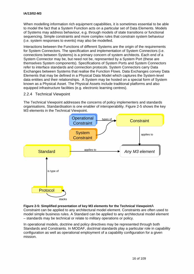
The Technical Viewpoint addresses the concerns of policy implementers and standards organisations. Standardisation is one enabler of interoperability. Figure 2-5 shows the key M3 elements in the Technical Viewpoint.
Figure 2-5: Simplified presentation of key M3 elements for the Technical ViewpointA Constraint can be applied to any architectural model element. Constraints are often used to model simple business rules. A Standard can be applied to any architectural model element – standards may be technical or relate to military operations or policy.
In operational models, doctrine and policy directives may be represented through both Standards and Constraints. In MODAF, doctrinal standards play a particular role in capability configuration as well as operational employment of a capability configuration for a given mission.
StandardStandard Any M3 elementAny M3 elementapplies to
ProtocolProtocol
is type of
applies to
ConstraintConstraint
stacks
SystemConstraintSystem
Constraint
OperationalConstraint
OperationalConstraint
types of
IA/13/02-M3
17 of 109
In system models, technical standards may be associated with System Functions and Physical Data Models. A Protocol is a special type of Standard that relates to System Connectors. Protocols may be nested in Protocol Stacks.
2.2.5 Acquisition Viewpoint
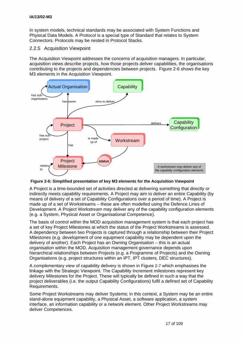
The Acquisition Viewpoint addresses the concerns of acquisition managers. In particular, acquisition views describe projects, how those projects deliver capabilities, the organisations contributing to the projects and dependencies between projects. Figure 2-6 shows the key M3 elements in the Acquisition Viewpoint.
Figure 2-6: Simplified presentation of key M3 elements for the Acquisition Viewpoint
A Project is a time-bounded set of activities directed at delivering something that directly or indirectly meets capability requirements. A Project may aim to deliver an entire Capability (by means of delivery of a set of Capability Configurations over a period of time). A Project is made up of a set of Workstreams – these are often modelled using the Defence Lines of Development. A Project Workstream may deliver any of the capability configuration elements (e.g. a System, Physical Asset or Organisational Competence).
The basis of control within the MOD acquisition management system is that each project has a set of key Project Milestones at which the status of the Project Workstreams is assessed. A dependency between two Projects is captured through a relationship between their Project Milestones (e.g. development of one equipment capability may be dependent upon the delivery of another). Each Project has an Owning Organisation – this is an actual organisation within the MOD. Acquisition management governance depends upon hierarchical relationships between Projects (e.g. a Programme of Projects) and the Owning Organisations (e.g. project structures within an IPT, IPT clusters, DEC structures).
A complementary view of capability delivery is shown in Figure 2-7 which emphasises the linkage with the Strategic Viewpoint. The Capability Increment milestones represent key delivery Milestones for the Project. These will typically be defined in such a way that the project deliverables (i.e. the output Capability Configurations) fulfil a defined set of Capability Requirements.
Some Project Workstreams may deliver Systems; in this context, a System may be an entire stand-alone equipment capability, a Physical Asset, a software application, a system interface, an information capability or a network element. Other Project Workstreams may deliver Competences.
ProjectProject
ProjectMilestoneProject
Milestone
has
is made up of
has owner
statusstatus
WorkstreamWorkstreamhas sub-project
relatesto
CapabilityCapability
aims to deliver
CapabilityConfigurationCapability
Configurationdelivers
A workstream may deliver any of the capability configuration elements
has sub-organisation
Actual OrganisationActual Organisation

IA/13/02-M3
18 of 109
Figure 2-7: Simplified presentation of capability delivery
A Project may deliver the whole System, its associated Physical Asset, a component part of the System or a Capability Configuration of which the System forms a part. When a System forms part of a Capability Configuration in combination with an Organisational Resource, the System Functions that are provided by the System should support those Operational Activities that are conducted by that Organisational Resource.
The M3 is intended to be sufficiently flexible that transformational programmes can be addressed. Such programmes will have some sub-projects that deliver capability in the traditional sense (as discussed in the previous paragraphs) and others that deliver benefit in different ways. In the case of transformational Programmes, it may not be appropriate for the Project Workstreams to be based on the Lines of Development.
has milestoneProjectProject
CapabilityRequirementCapability
Requirement
CapabilityIncrement
CapabilityIncrement
delivers
CapabilityConfigurationCapability
Configuration
has project deliverablesforming
fulfils

IA/13/02-M3
19 of 109
2.3 Viewpoint Linkages
The colour-coding in the figures in Section 2.2 provides an indication of the main linkages between the viewpoints listed in Section 2.1. Figure 2-8 provides a summary view of these linkages.
Figure 2-8: Representation of viewpoint linkages
Figure 2-8 should be interpreted as follows. A bold arrow indicates that some architectural elements from the source Viewpoint are shared with the destination Viewpoint. For example, ActualOrganisation is shared between the Operational and Acquisition Viewpoints. Architectural elements are associated with Viewpoints through the use of packages in the model (see Section 4.1).
Enterprise architects need to pay attention to the linking elements shown in Figure 2-8 because these elements enable correct top-to-bottom linkage to be achieved across the multiple layers of an Enterprise Architecture model.
It is striking that the Strategic Viewpoint (representing the business perspective at the enterprise level) is central in this figure.
Figure 2-8 also shows the level of integration that has been achieved between the DoDAF viewpoints (Operational, System, Technical) with the two viewpoints (Strategic, Acquisition) that are new in MODAF.
System ViewpointSystem Viewpoint
Acquisition ViewpointAcquisition Viewpoint
Operational ViewpointOperational Viewpoint
Technical ViewpointTechnical Viewpoint
systemsystem
projectproject
standardstandard
standardstandard
physicalasset
physicalasset
milestonemilestone
enduringtaskenduring
task
capabilityconfigurationcapability
configuration
actualorganisationactual
organisation
capabilitycapability
capabilitycapability
capabilityconfigurationcapability
configuration
capabilityconfigurationcapability
configuration
Strategic ViewpointStrategic Viewpointinformationexchangeinformation
exchange
nodenode
operationalactivityoperational
activity
organisationorganisationorganisationorganisation
operationalactivityoperational
activity
capabilityincrementcapability
increment

IA/13/02-M3
20 of 109
2.4 High Level Presentation of Key M3 Elements Against Views
The internal coherence of an architecture model depends upon correct re-use of those M3 elements that may appear in several MODAF views. Figure 2-9 provides the next level of detail in identifying those architectural elements that appear in more than one view. OV-1 is omitted because a large number of different M3 elements could potentially be included on a high level operational concept diagram.
Figure 2-9: View linkage through M3 elements
Note that the following MODAF views are explicitly defined in order to provide linkages between views:
SV-5 provides a link between SV-4 and OV-5
SV-2c provides a link between SV-2a, SV-2b and SV-1.
In defence procurement terms, the first two of these provide requirements traceability (from system requirements to user requirements to capability requirements).
OV-6
OV-5
OV-2
StV-3 StV-5
SV-8*
SV-7*
SV-3
SV-6*
OV-4
Post
StV-4
CapabilityDependency
Capability Configuration † (also AcV-2)
OV-3
Node
Needline
Information Exchange
ActivityFlow
OperationalEvent
SV-11OV-7
Entity Entity
Data model
Information Element
SV-4 SV-10
ObjectFlow
SV-5
Function
AcV-1
AcV-2
Project†
Milestone†
Thread
Projectoutput †
Organisation
System*
StV-1
† = time-constrained item
OV-1 may share elements from OV-2 (OV-1 not included explicitly)
Standard† (TV-1, TV-2) may apply to elements in any view
* = includes measurable properties
StV-6StV-2*
CapabilitySpecification
PortSystem Connection* SV-2c
Physical Asset
Operational Activity
Capability Composition
Capability Requirement* † (also AcV-2)
CapabilityVision†
SV-2
SV-1*
Link covered by MODAF viewLink covered by MODAF viewLink covered by MODAF view
FieldedCapability
Enduringtask

IA/13/02-M3
21 of 109
3 M3 Specification
3.1 Introduction to the M3
The M3 model is presented in HTML format [2] and is presented:
• for each of the six MODAF viewpoints: All Views, Strategic, Operational, Systems, Technical and Acquisition
• view by view (a sub-set of the model is presented for each view defined in the MODAF Handbook [1]).
In the view-by-view diagrams, the base UML meta-classes are shown being extended by the MODAF stereotype definitions. Each view-by-view diagram has a short explanatory text, describing how the model is used to support the view. Each stereotype also has a definition text which refers to all significant attributes.
There are some key assumptions and short-cuts that have been made in modelling the M3:
1. Anyone implementing this specification will need the UML 2.0 Superstructure [3] and UML 2.0 Infrastructure [4] specification documents and the XMI 2.1 specification [5].
2. UML stereotypes are defined by extending UML meta-classes. The UML tool used in producing the M3 did not have extension relationships (filled arrows). A thick association arrow (stereotyped to “extends”) has been used as a work-around. UML meta-classes are coloured green.
3. There is no simple mechanism to constrain the relationships that are possible between stereotyped elements, and this is vital to ensure that the MODAF exchange files are sensible and compliant. Rather than embed OCL constraints in the meta-model, a short-hand has been used. Relationships that are defined on the base meta-class are either subsetted or redefined in the stereotype extensions. For example, the NodeAssemblyUsage stereotype extends UML::CompositeStructures::InternalStructures::Property and redefines the type association end so that it can only refer to a Node stereotype and renames it to child. The renaming is purely informative (to provide a better idea of the purpose of the relationship) and has no impact on the XMI which would use the UML meta-class names. Subsetting tends to be used when the original UML name is suitable, but there is a need to restrict what the relationship can refer to. In strict UML terms, these redefinitions are actually new relationships, and relationships between stereotype definitions are illegal. However, it does provide a neat way to describe how the model is constrained.
4. In the same style as the previous short-cut, it has also been necessary to introduce some abstract stereotype definitions. Although this convention has no meaning in UML, it is used in the M3 wherever it is necessary to constrain a relationship to point at a choice of stereotypes. For example, the abstract stereotype OrganisationalResource is referred to by RoleInOrganisation which needs to refer to either an OrganisationType or a PostType. Abstract stereotype definitions cannot be instantiated in an XMI file. The abstract classes present their names in italic and are coloured blue in the model diagrams. Abstract stereotypes do not necessarily have a single UML base class.
5. In some of the view-by-view model diagrams some stereotypes are included which do not appear explicitly in the corresponding view product. These usually have the role of relating those architectural elements that are shown in the product to elements
IA/13/02-M3
22 of 109
in other products. If the stereotype cannot be displayed in the view product, its definition class is coloured grey. Note that future revisions to the MODAF Documentation may result in many of these architectural elements being allowed.
6. DiagramCompositeClass is used as a top-level class for a composite class diagram when it is not possible to use an architectural element as the top-level class. This usually arises when connections are required between two classes which are at the top level - which is not generally possible. In such a case, the two top-level architectural elements would be properties of the DiagramCompositeClass, enabling connections to be made between the properties.
7. Multiplicities of relationships should be assumed to be the same as those for the UML 2.1 base metaclasses they redeclare unless otherwise stated – i.e. if no multiplicity is shown on a relationship, don’t assume ‘1’, assume whatever was defined for the base metaclasses.
8. Wherever there was an unambiguous overlap with SysML, M3 has used the appropriate SysML construct. Imported SysML elements are colour-coded purple.
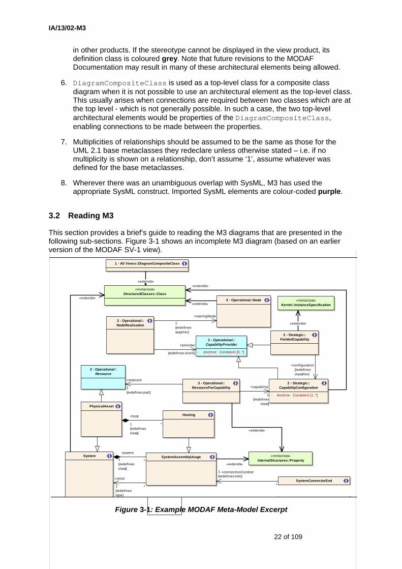
3.2 Reading M3
This section provides a brief’s guide to reading the M3 diagrams that are presented in the following sub-sections. Figure 3-1 shows an incomplete M3 diagram (based on an earlier version of the MODAF SV-1 view).
1 - All Views::DiagramCompositeClass
«metaclass»StructuredClasses::Class
«metaclass»InternalStructures::Property
SystemConnectorEnd
SystemAssemblyUsage
3 - Operational::NodeRealisation
3 - Operational::Node
System
2 - Strategic::FieldedCapability3 - Operational::
CapabilityProvider
- doctrine: Constraint [0..*]
PhysicalAsset
2 - Strategic::CapabilityConfiguration
- doctrine: Constraint [1..*]
3 - Operational::Resource
3 - Operational::ResourceForCapability
Hosting
«metaclass»Kernel::InstanceSpecification
«extends»*
+parent
1{redefinesclass}
+connectionContext1{redefines role}
*
+provider
{redefines client}
«extends»
+owningNode
1{redefinessupplier}
«extends»
+child
1{redefinestype}
*
+capabili ty
1{redefines
class}
+resource
1{redefines part}
«extends»
«extends»
*
+host
1{redefinesclass}
+configuration{redefinesclassifier}
«extends»
«extends»
Figure 3-1: Example MODAF Meta-Model Excerpt
IA/13/02-M3
23 of 109
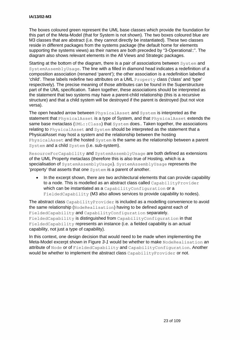
The boxes coloured green represent the UML base classes which provide the foundation for this part of the Meta-Model (that for System is not shown). The two boxes coloured blue are M3 classes that are abstract (i.e. they cannot directly be instantiated). These two classes reside in different packages from the systems package (the default home for elements supporting the systems views) as their names are both preceded by “3-Operational::”. The diagram also shows relevant elements in the All Views and Strategic packages.
Starting at the bottom of the diagram, there is a pair of associations between System and SystemAssemblyUsage. The line with a filled in diamond head indicates a redefinition of a composition association (renamed ‘parent’); the other association is a redefinition labelled ‘child’. These labels redefine two attributes on a UML Property class (‘class’ and ‘type’ respectively). The precise meaning of those attributes can be found in the Superstructure part of the UML specification. Taken together, these associations should be interpreted as the statement that two systems may have a parent-child relationship (this is a recursive structure) and that a child system will be destroyed if the parent is destroyed (but not vice versa).
The open headed arrow between PhysicalAsset and System is interpreted as the statement that PhysicalAsset is a type of System, and that PhysicalAsset extends the same base metaclass (UML::Class) that System does.. Taken together, the associations relating to PhysicalAsset and System should be interpreted as the statement that a PhysicalAsset may host a system and the relationship between the hosting PhysicalAsset and the hosted System is the same as the relationship between a parent System and a child System (i.e. sub-system).
ResourceForCapability and SystemAssemblyUsage are both defined as extensions of the UML Property metaclass (therefore this is also true of Hosting, which is a specialisation of SystemAssemblyUsage). SystemAssemblyUsage represents the ‘property’ that asserts that one System is a parent of another.
• In the excerpt shown, there are two architectural elements that can provide capability to a node. This is modelled as an abstract class called CapabilityProvider which can be instantiated as a CapabilityConfiguration or a FieldedCapability (M3 also allows services to provide capability to nodes).
The abstract class CapabilityProvider is included as a modelling convenience to avoid the same relationship (NodeRealisation) having to be defined against each of FieldedCapability and CapabilityConfiguration separately. FieldedCapability is distinguished from CapabilityConfiguration in that FieldedCapability represents an instance (i.e. a fielded capability is an actual capability, not just a type of capability).
In this context, one design decision that would need to be made when implementing the Meta-Model excerpt shown in Figure 3-1 would be whether to make NodeRealisation an attribute of Node or of FieldedCapability and CapabilityConfiguration. Another would be whether to implement the abstract class CapabilityProvider or not.
IA/13/02-M3
24 of 109
3.3 M3 Presented View-by-View
3.3.1 AV-1 MODAF Meta-Model Support
cd AV-1
«metaclass»Kernel::
InstanceSpecification
«metaclass»Kernel::Class
isAbstract: = false
View
framework: stringframeworkWebsite: stringviewCode: stringviewDescription: stringviewName: string
ArchitecturalProduct
architecturalElements: Element [1..*]description: string
ArchitecturalFramework
MetaData
dublinCoreElement: stringmodMetaDataElement: stringname: string
«metaclass»Kernel::Comment
body: String
«metaclass»Kernel::Package
ArchitecturalDescription
approvalAuthority: stringarchitect: stringassumptionsAndConstraints: stringcreatingOrganisation: stringdateCompleted: stringpurpose: stringrecommendations: stringsummaryOfFindings: stringtoolsUsed: stringviewpoint: string
IEEE1471:"View"
IEEE1471: "Viewpoint"
«metaclass»UseCases::Actor
«metaclass»UseCases::
UseCase
Concern
AV-1 now attempts to replicate the IEEE1471 specification wherever possible. It should be noted that 1471 is directed towards technical architectures, and MODAF is therefore broader in scope.
Note: in IEEE1471, the architectural description "identifies" (i.e. addresses) concerns. In general, we need something more fine grain than this - concerns may be addressed by some architectural products and not by others. Hence MODAF uses a relationship between the product and the concern.
«metaclass»Dependencies::Dependency
Stakeholder
StakeholderHasConcern
Enterprise «metaclass»Dependencies::
Abstraction
ArchitectureIEEE1471:System
«metaclass»BasicActiv ities::
Activ ity
3 - Operational::Mission
Env ironment
ArchitecturalReference
ArchitectureMetaData
addressedBy*{redefines subject}
addresses *{redefines useCase}
«extends»
«extends»
definingFramework
1{redefinesowningPackage}
1..*{subsets
ownedMember}
«extends»
0..1
usedToCover
*{redefinesownedUseCase}
owningArchitecture1{redefines owningPackage}
products1..*{subsets ownedMember}
«extends»
annotatedArchitecture
{redefines annotatedElement}
«extends»
fulfils1..*{redefinesownedBehavior}
referrer{redefines cl ient}
referred
{redefines supplier}
inhabits {redefines useCase}
influences{redefines subject}
«extends»
«extends»
enterprise
{redefines supplier}
definingView
1{redefinesclassifier}
*
«extends»
«extends»
«extends»
{subsets supplier}
{subsets client}
«extends»
«extends»
«extends»
describedBy
{redefines client}
Figure 3-2: MODAF Meta-Model Excerpt for AV-1
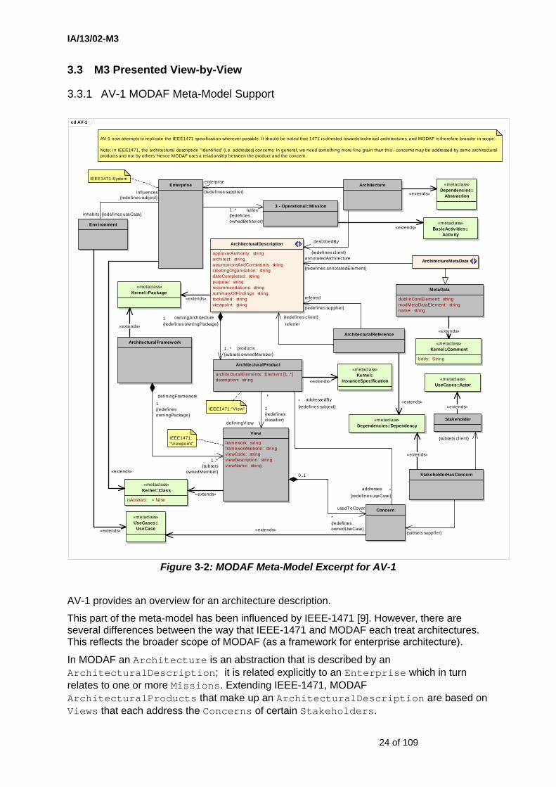
AV-1 provides an overview for an architecture description.
This part of the meta-model has been influenced by IEEE-1471 [9]. However, there are several differences between the way that IEEE-1471 and MODAF each treat architectures. This reflects the broader scope of MODAF (as a framework for enterprise architecture).
In MODAF an Architecture is an abstraction that is described by an ArchitecturalDescription; it is related explicitly to an Enterprise which in turn relates to one or more Missions. Extending IEEE-1471, MODAF ArchitecturalProducts that make up an ArchitecturalDescription are based on Views that each address the Concerns of certain Stakeholders.

IA/13/02-M3
25 of 109
The ArchitecturalDescription package contains all the architectural elements for a given architecture endeavour. There are a number of properties (tagged values) pre-defined for the architecture. However, an architect may wish to append additional information about the architecture using the ArchitectureMetaData stereotype.
Architectures do not stand alone. In MODAF one ArchitecturalDescription may refer to another.
IA/13/02-M3
26 of 109
3.3.2 AV-2 MODAF Meta-Model Support
cd AV-2
ClassifiedElement
classifications: string [0..*]taxonomy: Taxonomy
2 - Strategic::CapabilityRequirement
MeasurableProperty
maxValue: LiteralSpecification [0..1]minValue: LiteralSpecification [0..1]
3 - Operational::LocationType
3 - Operational::OperationalActiv ity
3 - Operational::Node
3 - Operational::InformationExchange
identifier: stringrequirementText: string [0..1]
3 - Operational::Competence
3 - Operational::OperationalConstraint
nodeUsageContext: Property [0..1]
3 - Operational::PostType
3 - Operational::OrganisationType
3 - Operational::RoleInOrganisation
6 - Acquisition::ProjectType
Serv ices::Serv ice
4 - Systems::System
4 - Systems::SystemConnectionSpecification
Standard
identifier: stringpublishedWebsite: stringpublisher: stringratificationDate: TimeExpressionversion: stringwithdrawalDate: TimeExpression
Taxonomy
date: stringurl: stringversion: string
ArchitecturalDescription
approvalAuthority: stringarchitect: stringassumptionsAndConstraints: stringcreatingOrganisation: stringdateCompleted: stringpurpose: stringrecommendations: stringsummaryOfFindings: stringtoolsUsed: stringviewpoint: string
«metaclass»Kernel::
Package
An architectural description must use one or more taxonomies. These taxonomies shall be defined in OWL and referenced by a URL. The MODAF policy on taxonomy is currently in development. The approach shown here is intended to provide just the basic taxonomy referencing capabil ity. A later release of M3 is l ikely to enhance this capabil ity using something similar to RDF triples.
Each element below is subject to classification by one or more elements in the taxonomy.
SysML::Unit
SysML::Dimension
3 - Operational::InformationElement
4 - Systems::DataElement
4 - Systems::SystemFunction
systemUsageContext: Property
3 - Operational::NodeConnectionType
2 - Strategic::Effect
6 - Acquisition::OrganisationProjectRelationship
6 - Acquisition::ProjectThreadType
Env ironment
2 - Strategic::EnduringTask
«extends»«extends»
taxonomy
1..*{subsets ownedMember}
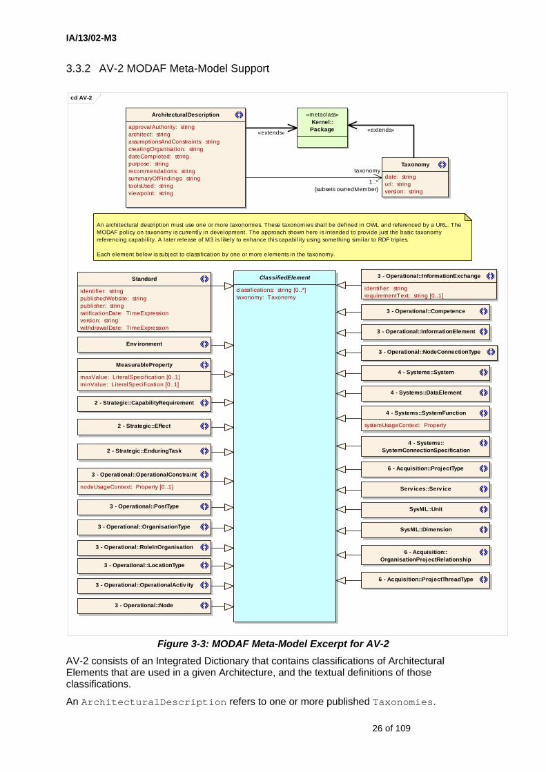
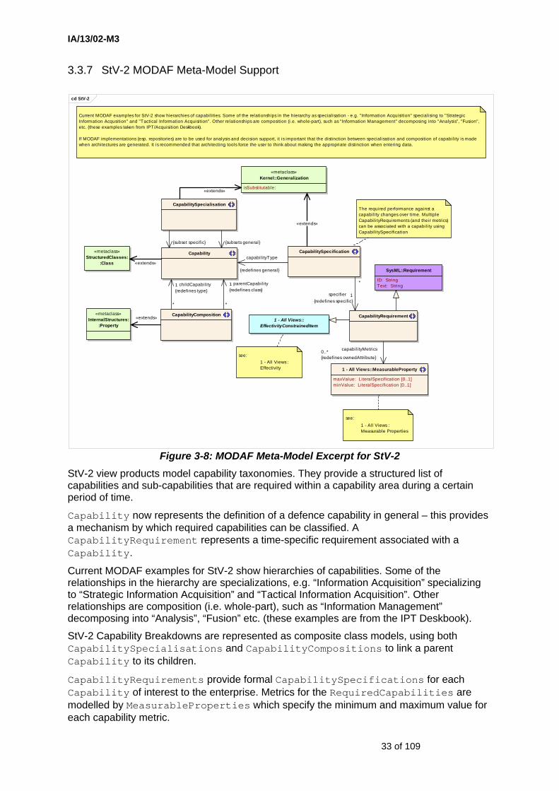
Figure 3-3: MODAF Meta-Model Excerpt for AV-2 AV-2 consists of an Integrated Dictionary that contains classifications of Architectural Elements that are used in a given Architecture, and the textual definitions of those classifications.
An ArchitecturalDescription refers to one or more published Taxonomies.

IA/13/02-M3
27 of 109
The MODAF taxonomy is due to be specified using the OWL-DL language, part of the W3C's semantic web suite of standards. AV-2 taxonomies are also represented as OWL-DL. Projects may extend the taxonomy with their own specific elements.
The suggested classified elements are shown explicitly in the lower part of Figure 3-3.
Users/vendors may also wish to embed RDF tags in M3 XMI exchange files to enable semantic web tools to search file contents.

IA/13/02-M3
28 of 109
3.3.3 MODAF Meta-Model Support For Effectivity Constraints
There are a number of places in the M3 where it is necessary to specify time-based constraints on meta-model elements. Such constraints are referred to as ‘Effectivity Constraints’.
cd Effectiv ity
EffectivityConstrainedItem
Effectiv ityConstraint ISO8601DateTimeTimePeriod
«metaclass»SimpleTime::
Interv al
«metaclass»SimpleTime::
TimeExpression
+ firstTime: = True
«metaclass»Kernel::
Constraint
+effectivityPeriod
1{redefines specification}
*
«extends»
1{subsets max}
*
1{subsets min}
*
«extends»«extends»
*{subset constrainedItem}
1
Figure 3-4: MODAF Meta-Model Excerpt for Effectivity Constraints
An EffectivityConstrainedItem refers to an EffectivityConstraint that is defined in terms of a TimePeriod; the latter is specified using minimum and maximum ISO8601DateTime elements.
IA/13/02-M3
29 of 109
3.3.4 MODAF Meta-Model Support For Measurable Properties
cd Measurable Properties
SysML::Unit
SysML::ValueType
dimension: DataTypeunit: DataType
SysML::Dimension
«metaclass»Kernel::
DataType
MeasurableProperty
maxValue: LiteralSpecification [0..1]minValue: LiteralSpecification [0..1]
«metaclass»Kernel::Property
isDerived: = falseisDerivedUnion: = falseisReadOnly: = false
There was always a wil l to bring the M3 property model in l ine with SysML. The SysML model has not become stable unti l recently (and there is sti l l a remote possibil ity of change). The model presented here is based on best information about the SysML "merged" document, though this was prior to final publication of the SysML specification.
The SysML approach relies on the defaultValue attribute on Property being set, then typed by a <<ValueType>>. The <<ValueType>> then refers to a <<Unit>> and a <<Dimension>>. Refer to the SysML specification for more details.
For M3, the stereotype <<MeasurableProperty>> has also been added. This allows maximum and minimum values to be set.
«metaclass»Kernel::
ValueSpecification
«metaclass»Kernel::
LiteralSpecification
owningProperty0..1{subsets owner}
defaultValue0..1{subsets ownedElement}
«extends»
«extends»
«extends»propertyValue
0..1{redefinesdefaultValue}
valueType
1{redefinesdatatype}
«extends»
Figure 3-5: MODAF Meta-Model Excerpt for Measurable Properties
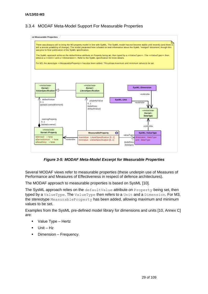
Several MODAF views refer to measurable properties (these underpin use of Measures of Performance and Measures of Effectiveness in respect of defence architectures).
The MODAF approach to measurable properties is based on SysML [10].
The SysML approach relies on the defaultValue attribute on Property being set, then typed by a ValueType. The ValueType then refers to a Unit and a Dimension. For M3, the stereotype MeasurableProperty has been added, allowing maximum and minimum values to be set.
Examples from the SysML pre-defined model library for dimensions and units [10, Annex C] are:
Value Type – Hertz
Unit – Hz
Dimension – Frequency.
IA/13/02-M3
30 of 109
3.3.5 MODAF Meta-Model Support For Requirements
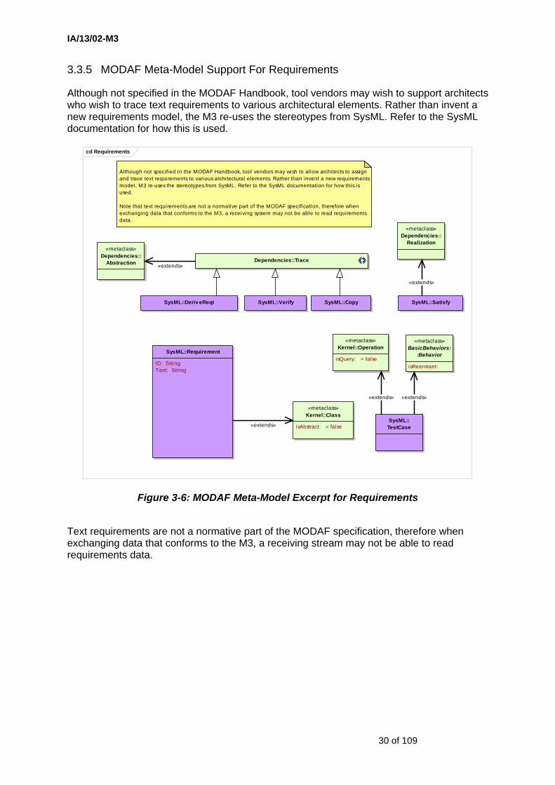
Although not specified in the MODAF Handbook, tool vendors may wish to support architects who wish to trace text requirements to various architectural elements. Rather than invent a new requirements model, the M3 re-uses the stereotypes from SysML. Refer to the SysML documentation for how this is used.
cd Requirements
SysML::Requirement
ID: StringText: String
Dependencies::Trace
«metaclass»Dependencies::
Abstraction
SysML::Deriv eReqt SysML::Verify
«metaclass»Dependencies::
Realization
SysML::Copy SysML::Satisfy
«metaclass»BasicBehaviors:
:Behavior
isReentrant:
«metaclass»Kernel::Operation
isQuery: = false
SysML::TestCase
«metaclass»Kernel::Class
isAbstract: = false
Although not specified in the MODAF Handbook, tool vendors may wish to allow architects to assign and trace text requirements to various architectural elements. Rather than invent a new requirements model, M3 re-uses the stereotypes from SysML. Refer to the SysML documentation for how this is used.
Note that text requirements are not a normative part of the MODAF specification, therefore when exchanging data that conforms to the M3, a receiving system may not be able to read requirements data.
«extends»«extends»
«extends»
«extends»
«extends»
Figure 3-6: MODAF Meta-Model Excerpt for Requirements
Text requirements are not a normative part of the MODAF specification, therefore when exchanging data that conforms to the M3, a receiving stream may not be able to read requirements data.

IA/13/02-M3
31 of 109
3.3.6 StV-1 MODAF Meta-Model Support
cd StV-1
see:
1 - All Views::EffectivityConstrainedItem
«metaclass»Kernel::Comment
+ body: String
CapabilityVision
«metaclass»StructuredClasses:
:Class
EnterpriseGoal
- benefits: string [0..*] {ordered}«metaclass»
InternalStructures::Property
GoalOfVision
VisionStatement
«metaclass»Dependencies::
Dependency
CapabilityContributesToVision
EnduringTask
«metaclass»BasicBehav iors::OpaqueBehav ior
+ body: String [1..*] {ordered}+ language: String [0..*] {ordered}
TaskAchiev esGoal
1 - All Views : Effectivity
Capability
Previous M3 versions treated StV-1 as li ttle more than free text. It became apparent from CoI Deskbook work that these may be structured - indeed all examples shown in the Handbook and Deskbooks have sub-sections describing individual goals of the vision. It is also clear that these goals describe future capabil ities, and it is useful to be able to map the goals to the capabilities. In addition, elements of the essential task list (JETL) were referenced in the visions, and it was clear that it would also be useful to refer to these explicitly.
A MODAF tool may not wish to implement this level of complexity, and simply record the vision as a single <<VisionStatement>>. However, it is strongly recommended that vendors encourage their users to populate the information as a <<Capabil ityVision>> with a <<VisionStatement>> as the introduction, followed by a set of <<EnterpriseGoal>>s complete with benefits if known.
+vision{redefines cl ient} «extends»
+statement
1{redefinesownedComment}
«extends»
«extends»
«extends»
+requiredGoal{redefines part}
«extends»
«extends»
«extends»
+contributingCapability
{redefines supplier}
+task
{redefinessupplier}
+goal {redefines cl ient}
«extends»
+vision
{redefines class}
Figure 3-7: MODAF Meta-Model Excerpt for StV-1 StV-1 addresses the enterprise concerns associated with the overall vision for transformational endeavours and thus defines the strategic context for a group of Enterprise capabilities.
Previous versions of the M3 treated StV-1 as little more than free text. It became apparent from CoI Deskbook work that these may be structured – indeed all the examples shown in the Handbook and Deskbooks have sub-sections describing individual goals of the vision. It is also clear that these goals describe future capabilities and it is useful to be able to map the goals to the capabilities. In addition, elements of the essential task list (JETL) were referenced in the example vision statements and it was clear that it would also be useful to refer to these explicitly.
A MODAF tool may not wish to implement this level of complexity, and simply record the vision as a single VisionStatement. However, it is strongly recommended that vendors encourage their users to populate the information as a CapabilityVision with a VisionStatement as the introduction, followed by a set of EnterpriseGoals.
XHTML might be used for the VisionStatement text if formatted text is required.

IA/13/02-M3
32 of 109
The time-dependent aspect of the CapabilityVision is achieved by applying an EffectivityConstraint. The TimePeriods are typically expressed in the form of time-bounded epochs.
M3 has been extended to encompass the definition of EnterpriseGoals that formalise the goals inherent in the CapabilityVision. Each EnterpriseGoal may encompass specific benefits.
The link with capabilities is that a set of Capabilities may be defined that contribute to the CapabilityVision. These support EnduringTasks (see StV-6) that achieve the EnterpriseGoals. Fulfilling the CapabilityRequirements (see StV-2) realises the associated benefits.
IA/13/02-M3
33 of 109
3.3.7 StV-2 MODAF Meta-Model Support
cd StV-2
see:
CapabilityRequirement
«metaclass»Kernel::Generalization
isSubstitutable:
CapabilitySpecialisation
Capability CapabilitySpecification
1 - All Views::EffectivityConstrainedItem
1 - All Views::MeasurableProperty
maxValue: LiteralSpecification [0..1]minValue: LiteralSpecification [0..1]
see:1 - All Views : Measurable Properties
1 - All Views : Effectivity
SysML::Requirement
ID: StringText: String
«metaclass»StructuredClasses:
:Class
CapabilityComposition«metaclass»InternalStructures:
:Property
Current MODAF examples for StV-2 show hierarchies of capabil ities. Some of the relationships in the hierarchy as specialisation - e.g. "Information Acquisition" specialising to "Strategic Information Acqusition" and "Tactical Information Acquisition". Other relationships are composition (i.e. whole-part), such as "Information Management" decomposing into "Analysis", "Fusion", etc. (these examples taken from IPT/Acquisition Deskbook).
If MODAF implementations (esp. repositories) are to be used for analysis and decision support, it is important that the distinction between specialisation and composition of capabil ity is made when architectures are generated. It is recommended that architecting tools force the user to think about making the appropriate distinction when entering data.
The required performance against a capability changes over time. Multiple Capabil ityRequirements (and their metrics) can be associated with a capabil ity using Capabil itySpecification
capabil ityMetrics0..*{redefines ownedAttribute}
«extends»
{subsets general}{subset specific}
«extends»
*
specifier 1{redefines specific}
«extends»
«extends»
*
parentCapability1{redefines class}
*
childCapabil ity1{redefines type}
capabil ityType
{redefines general}
Figure 3-8: MODAF Meta-Model Excerpt for StV-2 StV-2 view products model capability taxonomies. They provide a structured list of capabilities and sub-capabilities that are required within a capability area during a certain period of time.
Capability now represents the definition of a defence capability in general – this provides a mechanism by which required capabilities can be classified. A CapabilityRequirement represents a time-specific requirement associated with a Capability.
Current MODAF examples for StV-2 show hierarchies of capabilities. Some of the relationships in the hierarchy are specializations, e.g. “Information Acquisition” specializing to “Strategic Information Acquisition” and “Tactical Information Acquisition”. Other relationships are composition (i.e. whole-part), such as “Information Management” decomposing into “Analysis”, “Fusion” etc. (these examples are from the IPT Deskbook).
StV-2 Capability Breakdowns are represented as composite class models, using both CapabilitySpecialisations and CapabilityCompositions to link a parent Capability to its children.
CapabilityRequirements provide formal CapabilitySpecifications for each Capability of interest to the enterprise. Metrics for the RequiredCapabilities are modelled by MeasurableProperties which specify the minimum and maximum value for each capability metric.
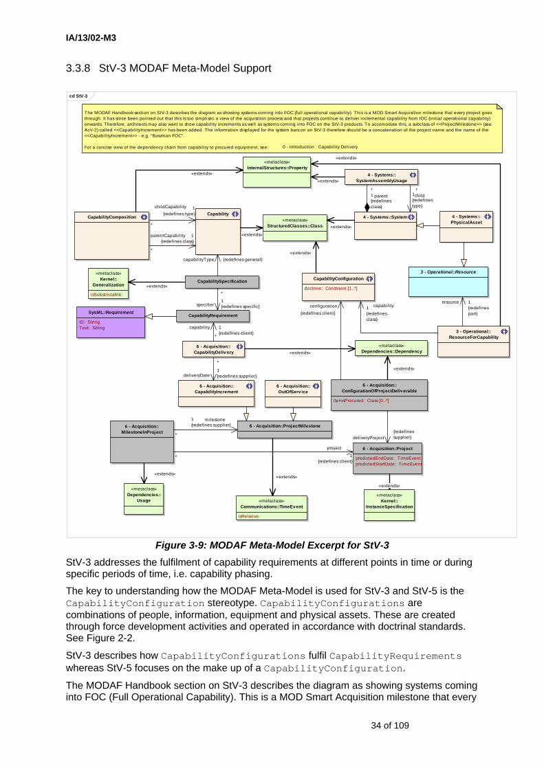
IA/13/02-M3
34 of 109
3.3.8 StV-3 MODAF Meta-Model Support
cd StV-3
«metaclass»InternalStructures::Property
CapabilityConfiguration
doctrine: Constraint [1..*]
«metaclass»StructuredClasses::Class
4 - Systems::SystemCapabilityComposition
CapabilityRequirement
3 - Operational::ResourceForCapability
3 - Operational::Resource
4 - Systems::PhysicalAsset
4 - Systems::SystemAssemblyUsage
6 - Acquisition::Project
predictedEndDate: TimeEventpredictedStartDate: TimeEvent
6 - Acquisition::ConfigurationOfProjectDeliverable
itemsProcured: Class [0..*]
6 - Acquisition::MilestoneInProject
6 - Acquisition::ProjectMilestone
6 - Acquisition::CapabilityIncrement
6 - Acquisition::OutOfServ ice
«metaclass»Dependencies::Dependency
«metaclass»Kernel::
InstanceSpecification
«metaclass»Dependencies::
Usage «metaclass»Communications::TimeEvent
isRelative:
SysML::Requirement
ID: StringText: String
Capability
CapabilitySpecification
«metaclass»Kernel::
Generalization
isSubstitutable:
6 - Acquisition::CapabilityDeliv ery
The MODAF Handbook section on StV-3 describes the diagram as showing systems coming into FOC (ful l operational capabili ty). This is a MOD Smart Acquisition milestone that every project goes through. It has since been pointed out that this is too simplistic a view of the acquisition process and that projects continue to deliver incremental capability from IOC (initial operational capabili ty) onwards. Therefore, architects may also want to show capabil ity increments as well as systems coming into FOC on the StV-3 products. To accomodate this, a subclass of <<ProjectMilestone>> (see AcV-2) called <<Capabil ityIncrement>> has been added. The information displayed for the system bars on an StV-3 therefore should be a concatenation of the project name and the name of the <<CapabilityIncrement>> - e.g. "Bowman FOC".
For a concise view of the dependency chain from capability to procured equipment, see: 0 - Introduction : Capability Delivery
resource 1{redefinespart}
«extends»
«extends»
«extends»
milestone1{redefines supplier}
*
«extends»
«extends»capabil ityType {redefines general}
«extends»
child1{redefinestype}
*
*
childCapability 1{redefines type}
*
parentCapabil ity 1{redefines class}
«extends»
*
deliveryDate1{redefines supplier}
«extends»
deliveryProject{redefinessupplier}
configuration{redefines client}
«extends»
capability1{redefinesclass}
«extends»
«extends»
project
1{redefines client}
*
«extends»
*parent1
{redefinesclass}
*
specifier1{redefines specific}
*
capability 1{redefines client}
Figure 3-9: MODAF Meta-Model Excerpt for StV-3 StV-3 addresses the fulfilment of capability requirements at different points in time or during specific periods of time, i.e. capability phasing.
The key to understanding how the MODAF Meta-Model is used for StV-3 and StV-5 is the CapabilityConfiguration stereotype. CapabilityConfigurations are combinations of people, information, equipment and physical assets. These are created through force development activities and operated in accordance with doctrinal standards. See Figure 2-2.
StV-3 describes how CapabilityConfigurations fulfil CapabilityRequirements whereas StV-5 focuses on the make up of a CapabilityConfiguration.
The MODAF Handbook section on StV-3 describes the diagram as showing systems coming into FOC (Full Operational Capability). This is a MOD Smart Acquisition milestone that every
IA/13/02-M3
35 of 109
equipment delivery project goes through. It has since been pointed out that this is too simplistic a view of the acquisition process and that projects continue to deliver incremental capability from IOC (Initial Operational Capability) onwards. Correspondingly, architects may also want to show capability increments as well as systems coming into FOC on the StV-3 products.
The link from capability to equipment is now via projects, using CapabilityIncrement and CapabilityDelivery. See Figure 2-7. This means that, even if only StV-3 & StV-5 are being produced, a Project must also be created, with the appropriate CapabilityIncrement milestones. This applies even if the equipment is already in service.
To accommodate this, a subclass of ProjectMilestone (see AcV-2) called CapabilityIncrement has been added. The information displayed for system bars on an StV-3 therefore should be a concatenation of the project name and the name of the CapabilityIncrement, e.g. “BOWMAN FOC”.
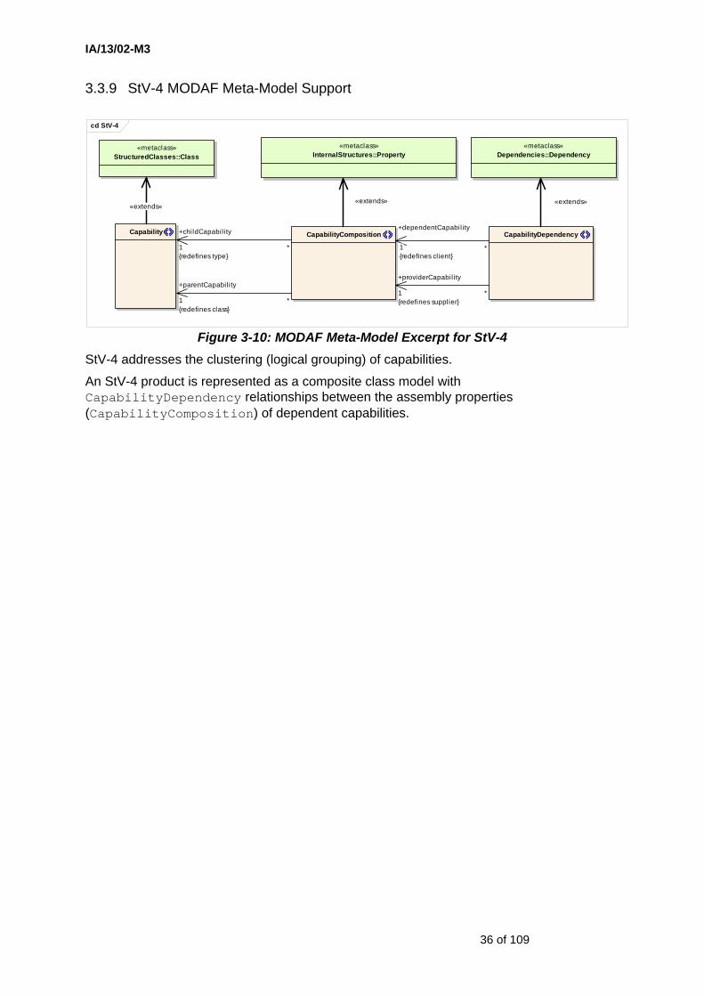
IA/13/02-M3
36 of 109
3.3.9 StV-4 MODAF Meta-Model Support
cd StV-4
«metaclass»InternalStructures::Property
«metaclass»Dependencies::Dependency
CapabilityDependencyCapabilityCompositionCapability
«metaclass»StructuredClasses::Class
«extends»«extends»
*
+childCapabil ity
1{redefines type}
*
+parentCapabil ity
1{redefines class}
«extends»
+dependentCapabil ity
1{redefines client}
*
+providerCapabil ity
1{redefines supplier}
*
Figure 3-10: MODAF Meta-Model Excerpt for StV-4 StV-4 addresses the clustering (logical grouping) of capabilities.
An StV-4 product is represented as a composite class model with CapabilityDependency relationships between the assembly properties (CapabilityComposition) of dependent capabilities.

IA/13/02-M3
37 of 109
3.3.10 StV-5 MODAF Meta-Model Support
cd StV-5
4 - Systems::SystemUsage
capabil i tyConfiguration: Classcontext: Property [0..1]
«metaclass»InternalStructures::Connector
«metaclass»InternalStructures::ConnectorEnd
CapabilityConfiguration
doctrine: Constraint [1..*]
3 - Operational::OrganisationalResource
«metaclass»StructuredClasses::Class
«metaclass»InternalStructures::Property
CapabilityRequirement
3 - Operational::OrganisationType
4 - Systems::System
In StV-5 capabili tyConfiguration attribute shall be a <<Capabil i tyConfiguration>> and userContext & systemContext shall be Properties stereotyped as <<ResourceForCapabil ity>>
4 - Systems::SystemConnectorEnd
4 - Systems::SystemConnector
capabili tyConfiguration: Class
4 - Systems::SystemAssemblyUsage
3 - Operational::ResourceForCapability
3 - Operational::Resource
SysML::NestedConnectorEnd
propertyPath: Property
4 - Systems::PhysicalAsset
The capabili ties shown in StV-5 are related to the systems shown via the project delivery pattern. See:
Each column in an StV-5 diagram is a <<Capabil i ty>>, and a <<Capabil ityConfiguration>> represents one or more cells in the StV-5. <<Capabili tyConfiguration>>requires that an OrganizationalResource or PhysicalAsset be used to host the systems shown in the diagram. The usage of systems by organizations is specified by the <<SystemUsage>> relationship.
6 - Acquisition::Project
predictedEndDate: TimeEventpredictedStartDate: TimeEvent
6 - Acquisition::OutOfServ ice
6 - Acquisition::CapabilityIncrement
6 - Acquisition::ProjectMilestone
6 - Acquisition::MilestoneInProject
«metaclass»Dependencies::
Dependency
«metaclass»Communications::TimeEvent
isRelative:
«metaclass»Dependencies::
Usage
6 - Acquisition::ConfigurationOfProjectDeliv erable
i temsProcured: Class [0..*]
1 - All Views::ISO8601DateTime
«metaclass»SimpleTime::
TimeExpression
firstTime: = True
Capability
CapabilitySpecification
«metaclass»Kernel::
Generalization
isSubstitutable:
SysML::Requirement
ID: StringText: String
6 - Acquisition::CapabilityDelivery
0 - Introduction : Capabil ity Delivery
«extends»
«extends»
2{subsets end}1
user
1{redefines
client}
«extends»
«extends»
project 1{redefines client}
*
«extends»
child
1{redefines type}
*
systemUsed
1{redefinessupplier}
milestone
1{redefines supplier}
*
*
deliveryDate 1{redefines supplier}
«extends»
*specifier1{redefines specific}
capabili tyType {redefines general}
«extends»
«extends»
1{redefines when}
*
«extends»deliveryProject
{redefines supplier}
configuration {redefines client}
«extends»
«extends»
*
capabili ty1{redefines client}
«extends»
connectionContext
1{redefines role}
*
«extends»
«extends»
«extends»
resource
1{redefines part}
capabil ity
1{redefines class}
*
parent
1{redefines class}
Figure 3-11: MODAF Meta-Model Excerpt for StV-5 StV-5 addresses the fulfilment of capability requirements, in particular by network enabled capabilities. It shows deployment of systems in types of organisations (e.g. echelons), and the connections between those systems, to satisfy the military capability for a particular period of time (or Epoch). When appropriate and if necessary an StV-5 view can show how all relevant Defence Lines of Development combine to provide a realised capability.

IA/13/02-M3
38 of 109
The key to understanding how the MODAF Meta-Model is used for StV-3 and StV-5 is the CapabilityConfiguration stereotype. CapabilityConfigurations are combinations of people, information, equipment and physical assets. These are created through force development activities and operated in accordance with doctrinal standards. See Figure 2-2.
StV-3 describes how CapabilityConfigurations fulfil CapabilityRequirements whereas StV-5 focuses on the make up of a CapabilityConfiguration.
Each column in an StV-5 diagram is a Capability and a CapabilityConfiguration represents one or more cells in the StV-5.
CapabilityConfiguration requires that an OrganisationalResource or PhysicalAsset is used to host the systems shown in the diagram. StV-5 extends StV-3 by explicitly bringing in the PhysicalAssets from which a CapabilityConfiguration may be created. Equipment capabilities (i.e. Systems) contribute to a Capability by being hosted on PhysicalAssets.
This means that an instance of a PhysicalAsset may have staff and/or equipment configured for it, then (and only then) it becomes a CapabilityConfiguration able to fulfil CapabilityRequirements. In addition an instance of an OrganisationType may be configured as a capability resource so that it becomes a CapabilityConfiguration.
The deployment of an Organisation to a PhysicalAsset is addressed through the OrganisationDeployedToPhysicalAsset stereotype (see SV-1).
A CapabilityRequirement or group of CapabilityRequirements may only be achievable by a connected configuration of systems (i.e. "network-enabled capability"). This is addressed through SystemsConnector (see SV-1).
The usage of Systems by OrganisationalResources is specified by the SystemUsage relationship.
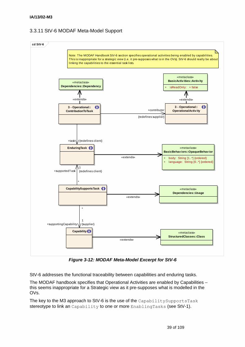
IA/13/02-M3
39 of 109
3.3.11 StV-6 MODAF Meta-Model Support
cd StV-6
«metaclass»Dependencies::Usage
EnduringTask «metaclass»BasicBehav iors::OpaqueBehav ior
+ body: String [1..*] {ordered}+ language: String [0..*] {ordered}
Note: The MODAF Handbook StV-6 section specifies operational activities being enabled by capabili ties. This is inappropriate for a strategic view (i.e. it pre-supposes what is in the OVs). StV-6 should really be about l inking the capabili ties to the essential task l ists.
CapabilitySupportsTask
Capability «metaclass»StructuredClasses::Class
3 - Operational::ContributionToTask
3 - Operational::OperationalActiv ity
«metaclass»Dependencies::Dependency
«metaclass»BasicActiv ities::Activ ity
+ isReadOnly: = false
«extends»
+task {redefines client}
+contributer
{redefines supplier}
«extends»
«extends»
*
+supportedTask1{redefines client}
«extends»
*
+supportingCapabil ity1{supplier}
«extends»
Figure 3-12: MODAF Meta-Model Excerpt for StV-6
StV-6 addresses the functional traceability between capabilities and enduring tasks.
The MODAF handbook specifies that Operational Activities are enabled by Capabilities – this seems inappropriate for a Strategic view as it pre-supposes what is modelled in the OVs.
The key to the M3 approach to StV-6 is the use of the CapabilitySupportsTask stereotype to link an Capability to one or more EnablingTasks (see StV-1).

IA/13/02-M3
40 of 109
Note that the original intent of the MODAF handbook form of StV-6 (as a mapping between capability elements and the operational activities that those capabilities support) is preserved in M3 as a result of the link between OperationalActivities and EnablingTasks (see also OV-5).

IA/13/02-M3
41 of 109
3.3.12 OV-1 MODAF Meta-Model Support
cd OV-1
LocationType
«metaclass»StructuredClasses::Class
«metaclass»InternalStructures::
Property
ConceptItem
ItemInConcept
iconHeight: inticonPositionX: inticonPositionY: inticonURL: stringiconWidth: int
HighLevelOperationalConcept
backgroundImageSizeX: intbackgroundImageSizeY: intbackgroundImageURL: string
ActualLocation
locationDescription: string
ReferredLocation
Mission «metaclass»BasicActiv ities::Activ ity
isReadOnly: = false
2 - Strategic::CapabilityConfiguration
doctrine: Constraint [1..*]
4 - Systems::FieldedCapability
«metaclass»Kernel::
InstanceSpecification
ConceptDescription
«metaclass»Kernel::Comment
body: StringAspectOfHLOC
locationType: Class [0..1]
1 - All Views::EffectivityConstrainedItem
HLOCAspect
1 - All Views::MeasurableProperty
maxValue: LiteralSpecification [0..1]minValue: LiteralSpecification [0..1]
see:
1 - All Views : Measurable Properties
In addition to these elements, any relationship from OV-2 may also be shown.
Node
see:1 - All Views : Effectivity
Although most DoDAF OV-1 products are simple graphical objects, there has been some demand from the vendor community for a more detai led representation in OV-1a in MODAF. To accomodate this, the M3 model has been extended to allow each graphical element to be a representation of elements found elsewhere in the architecture (subclasses of ConceptItem). A very simplistic image referencing, sizing and positioning model is included to enable a certain degree of layout consistency when data is exchanged between tools. Note that layout information is only provided for OV-1a because the meaning of the product is highly dependent on relative positions of the elements.
In cases where the OV-1 product is simply a graphic, a <<HighLevelOperationalConcept>> should be created, with the backgroundImageURL attribute referring to the graphic.
configuration {redefines classifier}
«extends»
«extends»
«extends»
«extends»
itemInScenario
1{redefines type}
*
«extends»
mission
0..*{redefines
ownedBehaviour}
owningScenario
1{redefines class}
*
concept1{redefinesannotatedElement}
*{subsetspart}
whole1{redefinesclass}
«extends»
operationalMetrics
0..*{redefines
ownedAttribute}
«extends»
«extends»«extends»
Figure 3-13: MODAF Meta-Model Excerpt for OV-1 OV-1 addresses the high level operational concepts related to one or more missions. An OV-1 describes a mission, class of mission, or scenario; and highlights the main operational elements and interesting or unique aspects of operations. It provides a description of the interactions between the architecture and its environment, and between the architecture and external systems. The OV-1 should combine graphics (OV-1a) and textual descriptions (OV-1b). The OV-1c view provides detail of the operational performance attributes associated with the mission/scenario represented in the OV-1a.
OV-1b adds a textual description of the high level concept of operations graphic shown in OV-1a by using a stereotype of Comment - ConceptDescription.
OV-1c adds properties to the high level concept of operations from OV-1a by using the MeasurableProperty stereotype.
Although most DoDAF OV-1 products are graphical objects, there has been demand from the vendor community for a more detailed representation in OV-1a of MODAF. To accommodate this, the M3 has been extended to allow each graphical element to be a representation of elements found elsewhere in the architecture (sub-classes of ConceptItem). A simple image referencing, sizing and positioning model is included to enable a certain degree of layout consistency when data is exchanged between tools.

IA/13/02-M3
42 of 109
Layout information is only provided in OV-1 because the meaning of this product is highly dependent upon the relative positions of the elements.
In cases where the OV-1a product is simply a graphic, a HighLevelOperationalConcept should be created, with the backgroundImageURL attribute set to refer to the graphic.
AspectOfHLOC has been added to represent the epochs covered by a HighLevelOperationalConcept in OV-1. It is this architectural element that has metrics associated with it. AspectOfHLOC optionally includes the types of location for which the HighLevelOperationalConcept metrics are valid.

IA/13/02-M3
43 of 109
.
3.3.13 OV-2 MODAF Meta-Model Support
cd OV-2
Activ ityConductedAtNode
nodeUsageContext: Property
«metaclass»Dependencies::Dependency
ReferredLocation
LocationType
1 - All Views::DiagramCompositeClass
NodeConnectionType
«metaclass»AssociationClasses::AssociationClass
«metaclass»StructuredClasses::Class
«metaclass»InternalStructures::Property
InformationExchange
identifier: stringrequirementText: string [0..1]
«metaclass»InternalStructures::
Connector
NodeConnector
NodeConnectionEnd
«metaclass»InternalStructures:
:ConnectorEnd
SysML::NestedConnectorEnd
propertyPath: Property
NodeAssemblyUsage
«metaclass»InformationFlows::InformationFlow
«metaclass»BasicActiv ities::
Activ ity
isReadOnly: = false
OperationalActiv ity
ActualLocation
locationDescription: string
RequiredNodeLocation
Needline
needlineNumber: int
Node
RealisationOfEffect 2 - Strategic::Effect
NodeAffectsNode
effect: Realization
constraints{effect.effector :=: fromNode}
«metaclass»Dependencies::Realization
«metaclass»BasicBehav iors::OpaqueBehav ior
body: String [1..*] {ordered}language: String [0..*] {ordered}
RequiredCapabilityForNode
2 - Strategic::CapabilityRequirement
SysML::Requirement
ID: StringText: String
The baseline documentation for MODAF (esp. the Handbook) attempted to adopt common usage patterns of DoDAF. It was apparent that many DoDAF users preferred to show system nodes and systems ontheir OV-2 products. It has since become apparent that this is bad practice in DoDAF and should never have been considered for MODAF. Hence the M3 specifically disallows any "solutioneering" of this nature in OV-2. Nodes are purely logical collections of activities that produce, consume or manipulate information. It is possible to accomodate some physical aspects into OV-2 without pre-supposing a systems-based solution, and this is achieved through <<NodeConnector>> which enables physical flows to be overlayed for contextual purposes and <<NodeAffectsNode>> which allows directed effects to be overlayed.
This version of M3 also introduces the possibil ity to l ink OV-2 into the Strategic Views by using the <<RequiredCapabilityForNode>> dependency.
For an overview of capability deployment, see:
0 - Introduction : Capability Deployment
connectionContext
1{redefines role}
*«extends»
activityConducted1{redefines supplier}
*
*
node
1{redefines
client}
«extends»
parent1{redefinesclass}
*
1
2{subsets
end}
«extends»
supportingNeedlines*{redefines realizingConnector}
1..*«extends»
conductedAt
1{redefines
client}
*
fromNode1{subsets /endType}
*
toNode1{subsets /endType}
*
child1{redefinestype}
*
«extends»
*
node
1{redefinesclient}
*
requirement1{redefines supplier}
«extends»«extends»
effectAchieved
{redefines supplier}
action
{redefines client}
«extends»
«extends»
locatedAt1{redefines supplier}
«extends»
«extends»
«extends» 1{subsetstype}
*
«extends»
«extends»
2{subsetsend}
1
«extends»
Figure 3-14: MODAF Meta-Model Excerpt for OV-2
The Operational Node Connectivity Specification (OV-2) addresses localisation of operational capability. An OV-2 depicts Operational Nodes with Needlines between those Nodes that indicate a need to exchange information.
The baseline documentation for MOD attempted to adopt common usage patterns of DoDAF. It was apparent that many DoDAF users preferred to show system nodes and systems on their OV-2 products. It has since become apparent that this is bad practice and inappropriate for MODAF. Hence the M3 specifically disallows any “solutioneering” of this
IA/13/02-M3
44 of 109
nature in OV-2 for MODAF. Nodes are purely logical collections of activities that produce, consume and manipulate information.
It is possible to accommodate some physical aspects into OV-2 without pre-supposing a systems-based solution, and this is achieved through the NodeConnector stereotype which enables physical flows to be overlaid for contextual purposes and the NodeAffectsNode stereotype which allows directed effects to be overlaid.
The key stereotype in OV-2 is Node. Nodes may be assembled using a UML composite class diagram (using NodeAssemblyUsage to relate the parent Node to its children). Similarly, Nodes may be positioned at a location using the composite class technique (via RequiredNodeLocation or ActualNodeLocation).
Connections between Nodes are described using the NodeConnector stereotype (for flows of people, material or energy) and the Needline stereotype for flows of information. If connections between two top-level nodes (i.e. the top-most classes in a composite class model) then the DiagramCompositeClass stereotype should be used as the top-level class. In the M3, there is no restriction on the number of Needlines that can be modelled between two Nodes (although there are such restrictions in the MODAF Handbook currently).
Modelling the OperationalActivities which take place at Nodes is achieved using the ActivityConductedAtNode (dependency) stereotype. In most cases, the same classes of Node will conduct the same activities. However, if an activity is peculiar to one usage of a Node, the nodeUsageContext attribute on ActivityConductedAtNode indicates the property which owns the usage of the class.
While this is not depicted directly in the OV-2, it is possible to realise Nodes by either Services, FieldedCapabilities or CapabilityConfigurations (see SV-1). As shown in StV-5, a CapabilityConfiguration is constructed from one or more OrganisationalResources and/or one or more PhysicalAssets (with hosted Systems). A FieldedCapability is an actual instance of a CapabilityConfiguration.
The M3 for OV-2 also introduces the possibility to link OV-2 with Strategic views by using the RequiredCapabilityForNode stereotype.
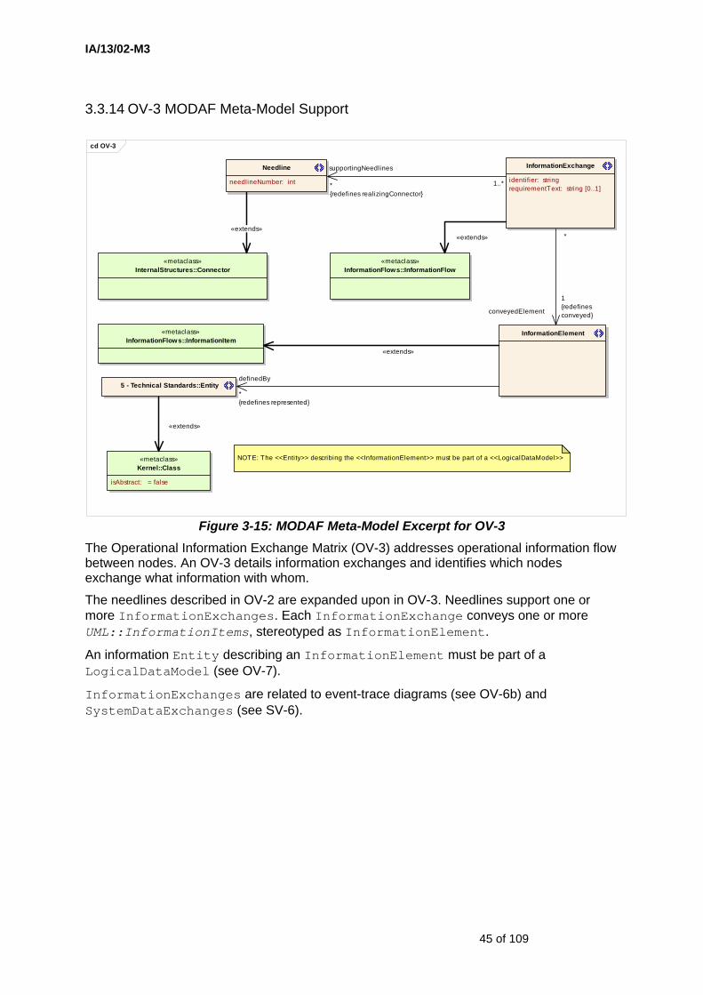
IA/13/02-M3
45 of 109
3.3.14 OV-3 MODAF Meta-Model Support
cd OV-3
«metaclass»Kernel::Class
isAbstract: = false
5 - Technical Standards::Entity
«metaclass»InternalStructures::Connector
«metaclass»InformationFlows::InformationFlow
«metaclass»InformationFlows::InformationItem
InformationElement
InformationExchange
identifier: stringrequirementText: string [0..1]
Needline
needlineNumber: int
NOTE: The <<Entity>> describing the <<InformationElement>> must be part of a <<LogicalDataModel>>
«extends»
conveyedElement
1{redefinesconveyed}
*
definedBy
*{redefines represented}
«extends»
«extends»«extends»
supportingNeedlines
*{redefines realizingConnector}
1..*
Figure 3-15: MODAF Meta-Model Excerpt for OV-3 The Operational Information Exchange Matrix (OV-3) addresses operational information flow between nodes. An OV-3 details information exchanges and identifies which nodes exchange what information with whom.
The needlines described in OV-2 are expanded upon in OV-3. Needlines support one or more InformationExchanges. Each InformationExchange conveys one or more UML::InformationItems, stereotyped as InformationElement.
An information Entity describing an InformationElement must be part of a LogicalDataModel (see OV-7).
InformationExchanges are related to event-trace diagrams (see OV-6b) and SystemDataExchanges (see SV-6).

IA/13/02-M3
46 of 109
3.3.15 OV-4 MODAF Meta-Model Support
cd OV-4
1 - All Views::DiagramCompositeClass
«metaclass»InternalStructures::Property
ActualOrganisationRelationship
typicalRelationship: Usage
ActualOrganisationalResource
ActualRoleInOrganisation
ActualPost
ActualOrganisation
«metaclass»Kernel::Slot
«metaclass»Kernel::InstanceSpecification
«metaclass»StructuredClasses::Class
«metaclass»Dependencies::Usage
OrganisationalResource
PostType
RoleInOrganisation
TypicalOrganisationRelationship
fromOrgRole: PropertytoOrgRole: Property
OrganisationType
«metaclass»Kernel::InstanceValue
OrgResourceReference
CompetenceResourceHasCompetence ActualCompetence
«metaclass»Dependencies::Dependency
OrgResourceConductsActiv ity
nodeAssemblyContext: Property [0..1]
OperationalActiv ity «metaclass»BasicActiv ities::Activ ity
isReadOnly: = false
RequiredCompetence
organisationType
1{redefines classifier}
*
resource
1{redefinessupplier}
1
«extends»
postType
1{redefinesclassifier}
*
«extends»
roleType
1{redefinesdefiningFeature}
*
roleRequiringCompetence
1
*
organisationOwningRole
1{redefines class}
*
fromOrg1{redefines supplier}
*toOrg 1
{redefines client}
*
«extends»
{subsets Part}
{subsetsclass}
«extends»
achievedCompetence
1{redefinessupplier}
1
requiredCompetence1
*
«extends»
fromOrg1{redefinessupplier}
*
«extends»activityConducted 1{redefines client}
1
«extends»
referredResource{redefinesInstance}
«extends»
«extends»
roleProvider1{redefines type}
*
«extends»
toOrg1{redefinesclient}
*
resourceWithCompetence1{redefinesclient}
1
resourceRef0..1{redefines value}
*
1{redefines
owningInstance}
«extends»
«extends»
Figure 3-16: MODAF Meta-Model Excerpt for OV-4 The Organisational Relationships Chart (OV-4) addresses the organisational aspect of an operational architecture. An OV-4 illustrates the command structure or relationships (as opposed to relationships with respect to a business process flow) among human roles, organisations, or organisation types that are the key players in an architecture.
OV-4 products may shown types of organisations and the typical structure of those organisations. This is represented as a composite class model. OV-4 products may also show actual, specific organisations (e.g. "The UK Ministry of Defence") and their structure, represented by instances and slots. In both the typical and specific cases, it is possible to overlay organisational relationships (Usages) which denote relationships between organisational elements that are not structural (e.g. a customer-supplier relationship).
Two types of architectural element may be shown in an OV-4: organisations and posts. Typical organisational structures are denoted using a UML composite structure diagram -

IA/13/02-M3
47 of 109
with parts being typed as either OrganisationType or PostType - the property that represents the parts is stereotyped as RoleInOrganisation.
Note that individual people are not modelled in MODAF, only types of posts.
Relationships between organisations which are not composite (e.g. contract relationships, supplier / consumer relationships, etc.) are modelled using a stereotype of Usage - TypicalOrganisationRelationship. The type of relationship is indicated by a reference to a MODAF Taxonomy element. The TypicalOrganisationRelationship relates two RoleInOrganisation properties - this allows relationships between specific usages of types of organisation to be modelled.
Similar syntax is provided for ActualOrganisations.

IA/13/02-M3
48 of 109
3.3.16 OV-5 MODAF Meta-Model Support
cd OV-5
«metaclass»Dependencies::Dependency
Activ ityConductedAtNode
nodeUsageContext: Property
InformationExchange
identifier: stringrequirementText: string [0..1]
«metaclass»InformationFlows::InformationFlow
«metaclass»StructuredClasses::Class
«metaclass»BasicActiv ities::ObjectFlow
«metaclass»BasicActions::
OutputPin
«metaclass»BasicActions::InputPin
«metaclass»BasicActions::CallBehav iorAction
«metaclass»BasicActiv ities::Activ ity
isReadOnly: = false
«metaclass»Dependencies::Usage
«metaclass»InformationFlows::InformationItem
InfoElementInFlow
InformationElement
OpActiv ityMechanismPin
OpActiv ityControlPin
OpActiv ityOutputPin
OpActiv ityInputPin
Node
OperationalActiv ityFlow
OperationalActiv ityAction
OperationalActiv ity
IDEF0FlowEnd
NodeProv idesControlOrMechanism
ActivitySubject
«metaclass»Kernel::Classifier
isAbstract: = false
«metaclass»Kernel::Association
isDerived: = false
ActsUpon
2 - Strategic::EnduringTask
«metaclass»BasicBehav iors::OpaqueBehav ior
body: String [1..*] {ordered}language: String [0..*] {ordered}
ContributionToTask
«metaclass»InternalStructures:
:Property
Activ ityComposition
cba: CallBehaviorAction
constraints{type :=: cba.behaviour}
This version of M3 introduces two ways to decompose Operational Activities. The first, which has been common to all M3 releases, uses the CallBehaviourAction approach. The new addition is the abil ity to use composite class diagrams to represent functional decomposition of activities. To ensure there is no conflict, the <<ActivityComposition>> refers to the corresponding <<OperationalActivityAction>> and constrains the referred child activities to be the same. SysML took the same approach.
«extends»
«extends»
«extends»
«extends»
conductedAt
1{redefines
client}
*
«extends»
inputPins
0..*{redefines /input}
1
realisingFlows 1..*{redefinesrealizingActivityEdge}*
«extends»equivalentActivity 1{redefines behaviour}
*
activityConducted
1{redefinessupplier}
*
subject 1{subsets
navigableOwnedEnd}activity1{subsetsmemberEnd}
«extends»
flow
1{redefines client}
*
«extends»
controlOrMechanism1{redefines client}
«extends»
task {redefines client}
contributer
{redefinessupplier}
«extends»
*
parent1{redefinesclass}
*
child 1{redefines
type}
«extends»
«extends»
flowTo 1{redefines target}
*
pin{redefinessupplier}
«extends»
element 1{redefines supplier}
*
conveyedElement 1{redefines conveyed}
*
«extends»
outputPins0..*{redefines /output}
*
fromFrom
1{redefines source}
*
«extends»
Figure 3-17: MODAF Meta-Model Excerpt for OV-5 The Operational Activity Model (OV-5) addresses operational functionality. An OV-5 describes the operations that are normally conducted in the course of achieving a mission or a business goal. It describes operational activities (or tasks), Input/Output (I/O) flows between activities, and I/O flows to/from activities that are outside the scope of the architecture.

IA/13/02-M3
49 of 109
The M3 aims to cover the basic process modelling techniques used by military modellers. The most widely used is IDEF0, though there are many other notations in use which have a similar level of functionality. As the M3 defines an abstract syntax for a UML profile, the basis for the model is the UML activity model. However, the UML activity model makes a distinction (which is unnecessary for MODAF purposes) between activity and action. In order to reconcile this with other modelling techniques (such as IDEF0) which allow sub-activities to be defined beneath an activity, it is necessary to constrain how the UML activity model is used for MODAF.
The M3 now supports two ways to decompose OperationalActivities. The first uses the CallBehaviourAction approach. The main constraint is that an Operational Activity (stereotyped on Activity) and an OperationalActivityAction (stereotyped on CallBehaviourAction) must be created for every activity that is modelled. This allows the sub-activities to be modelled in a similar way to IDEF0 without breaking the way UML is used. It is good modelling practice to create an activity and an action anyway because UML only allows properties to be defined against activities, but only allows flows between actions.
The second approach allows the use of composite class diagrams to represent functional decomposition of OperationalActivities. To ensure there is no conflict, the ActivityComposition refers to the corresponding OperationalActivityAction and constrains the referred child activities to be the same. This dual approach follows that taken by SysML.
Modelling the OperationalActivities which take place at Nodes is achieved using the ActivityConductedAtNode stereotype (see OV-2).
An OperationalActivity may act directly upon an InformationElement.

IA/13/02-M3
50 of 109
3.3.17 OV-6a MODAF Meta-Model Support
cd OV-6a
«metaclass»Kernel::Constraint
OperationalConstraint
nodeUsageContext: Property [0..1]
SubjectOfOperationalConstraint
OperationalActiv ityNodeMission
constrainedThing{redefines
constrainedElement}
«extends»
Figure 3-18: MODAF Meta-Model Excerpt for OV-6a The OV-6 products (OV-6a, OV-6b and OV-6c) address dynamic operational behaviour. The dynamic behaviour referred to here concerns the timing and sequencing of events that capture operational behaviour of a business process or mission thread for example.
An Operational Rules Model (OV-6a) specifies operational or business rules that are constraints on an enterprise, a mission, operation, business, or on an Architecture.
An operational constraint may be applied to anything to which a UML 2.0 constraint may be applied - i.e. UML:Element. This means that an operational constraint may be applied to virtually every element defined by the M3. Missions, Nodes and OperationalActivities are singled out in M3 as being typical subjects of OperationalConstraints.

IA/13/02-M3
51 of 109
3.3.18 OV-6b MODAF Meta-Model Support
cd OV-6b
Node
OperationalActiv ity
Behav iorStateMachines
(from StateMachines)
OperationalStateDescription
nodeUsageContext: Property [0..1]«metaclass»
Behav iorStateMachines::StateMachine
The whole UML State Machines meta-model can be used without stereotyping - apart from UML::BehaviourStateMachine which must be stereotyped to <<OperationalStateDescription>>. This is to distinguish the operational state description from the System State Machine in SV-10b
Mission
OperationalStateDescriptionOwner
{redefines context}
«extends»
Figure 3-19: MODAF Meta-Model Excerpt for OV-6b The Operational State Transition Description (OV-6b) is a graphical method of describing how an Operational Node or activity responds to various events by changing its state. The diagram represents the sets of events to which the Architecture will respond (by taking an action to move to a new state) as a function of its current state. Each transition specifies an event and an action.
For OV-6b and SV-10b, the complete use of stereotyping has not been deemed necessary - UML state machines are ideal for representing these products. However, to constrain the use and enable a distinction between OV-6b and SV-10b state models, the UML StateMachine meta-class is stereotyped to OperationalStateDescription for OV-6b and SystemStateMachine for SV-10b.
Missions, Nodes and OperationalActivities, which are the subjects of OperationalConstraints, can also be the subject of State Transition Descriptions.

IA/13/02-M3
52 of 109
3.3.19 OV-6c MODAF Meta-Model Support
cd OV-6c
OperationalNodeLifeline
nodeUsageContext: Property [0..1]
OperationalInteractionSpecification
BasicInteractions
(from Interactions)
«metaclass»BasicInteractions:
:Interaction
«metaclass»BasicInteractions:
:Lifeline
NodeAssemblyUsage
«metaclass»InternalStructures::Property
InformationExchangeMessage«metaclass»BasicInteractions::
Message
InformationExchange
identifier: stringrequirementText: string [0..1]
«metaclass»InformationFlows::
InformationFlow
0..*{redefinesrealizingMessage}
«extends»
«extends»
1{redefinesinteraction}
1{redefines lifel ine}
*{redefinesinteraction}
«extends»
«extends»
«extends»
1{redefines
represents}
*
Figure 3-20: MODAF Meta-Model Excerpt for OV-6c The Operational Event-Trace Description (OV-6c) provides a time-ordered examination of the interactions between participating Operational Nodes as a result of a thread within a mission. Each event-trace diagram will have an accompanying description that defines the mission thread.
For OV-6c and SV-10c, the complete use of stereotyping has not been deemed necessary - UML sequence (interaction) diagrams are ideal for representing these products. However, to constrain the use, and enable a distinction between OV-6c and SV-10c interaction models, the Interaction and Lifeline meta-classes are stereotyped.
In M3, InformationExchanges can be related to Operational Event-Trace descriptions through the use of the InformationExchangeMessage stereotype.
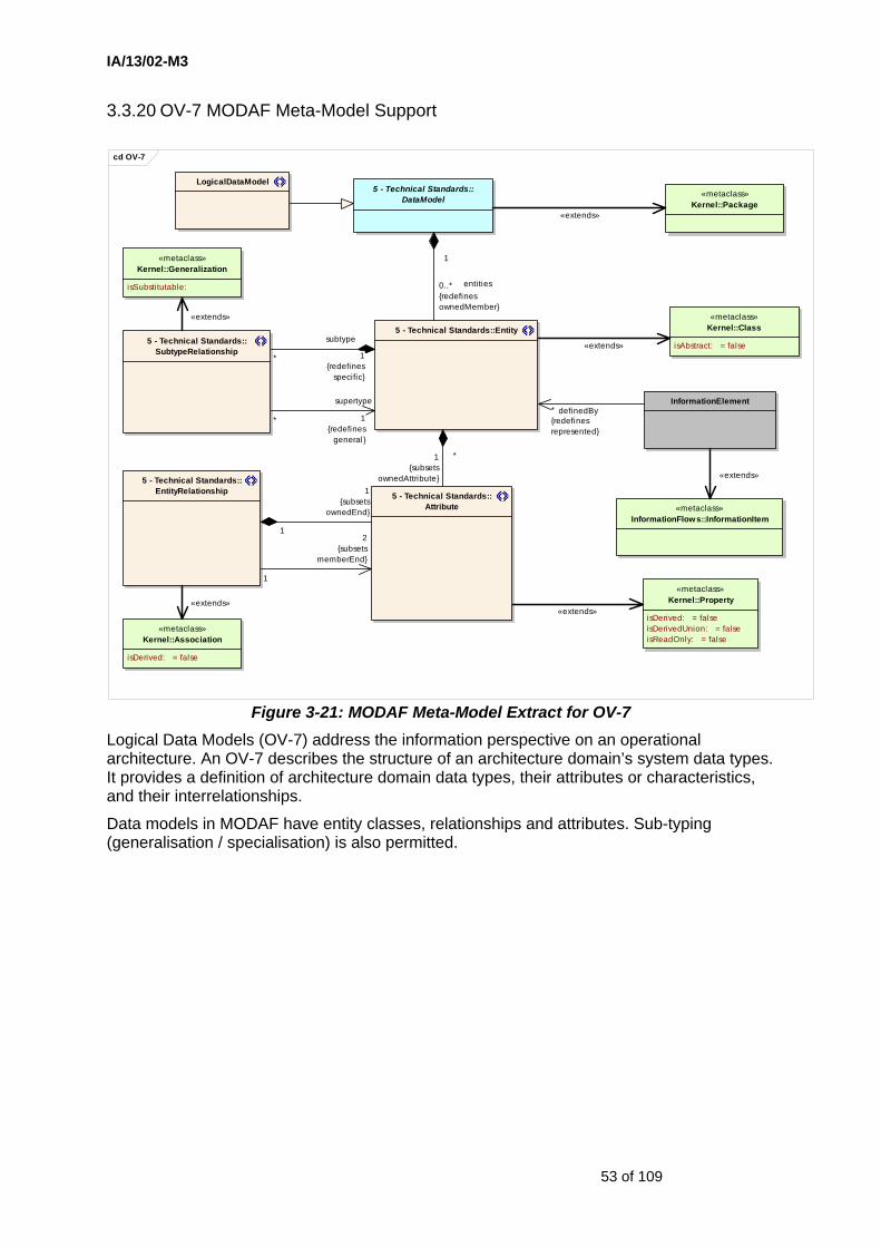
IA/13/02-M3
53 of 109
3.3.20 OV-7 MODAF Meta-Model Support
cd OV-7
LogicalDataModel
«metaclass»Kernel::Generalization
isSubstitutable:
«metaclass»Kernel::Association
isDerived: = false
«metaclass»Kernel::Property
isDerived: = falseisDerivedUnion: = falseisReadOnly: = false
«metaclass»Kernel::Class
isAbstract: = false
«metaclass»Kernel::Package
«metaclass»InformationFlows::InformationItem
InformationElement
5 - Technical Standards::EntityRelationship 5 - Technical Standards::
Attribute
5 - Technical Standards::SubtypeRelationship
5 - Technical Standards::Entity
5 - Technical Standards::DataModel
definedBy*{redefinesrepresented}
entities0..*{redefinesownedMember}
1
supertype
1{redefines
general}
*
«extends»*
subtype
1{redefines
specific}
«extends»
1{subsets
ownedEnd}
12
{subsetsmemberEnd}
1
1{subsets
ownedAttribute}
*
«extends»
«extends»
«extends»
«extends»
Figure 3-21: MODAF Meta-Model Extract for OV-7 Logical Data Models (OV-7) address the information perspective on an operational architecture. An OV-7 describes the structure of an architecture domain’s system data types. It provides a definition of architecture domain data types, their attributes or characteristics, and their interrelationships.
Data models in MODAF have entity classes, relationships and attributes. Sub-typing (generalisation / specialisation) is also permitted.
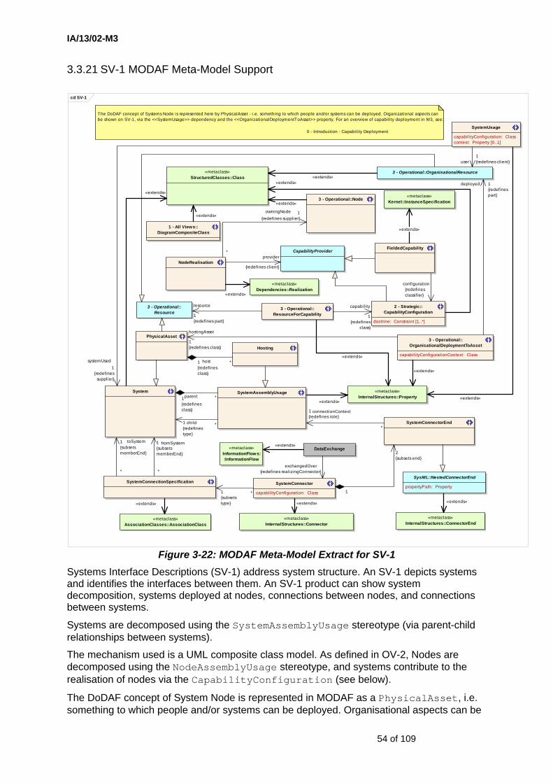
IA/13/02-M3
54 of 109
3.3.21 SV-1 MODAF Meta-Model Support
cd SV-1
1 - All Views::DiagramCompositeClass
«metaclass»StructuredClasses::Class
«metaclass»InternalStructures::Property
SysML::NestedConnectorEnd
propertyPath: Property
«metaclass»InternalStructures::Connector
SystemConnector
capabilityConfiguration: Class
SystemConnectorEnd
SystemAssemblyUsage
«metaclass»AssociationClasses::AssociationClass
SystemConnectionSpecification
NodeRealisation
3 - Operational::Node
System
«metaclass»InternalStructures::ConnectorEnd
FieldedCapabilityCapabilityProvider
PhysicalAsset
2 - Strategic::CapabilityConfiguration
doctrine: Constraint [1..*]
3 - Operational::ResourceForCapability
Hosting
«metaclass»Kernel::InstanceSpecification
DataExchange«metaclass»InformationFlows::InformationFlow
3 - Operational::Resource
3 - Operational::OrganisationalDeploymentToAsset
capabili tyConfigurationContext: Class
3 - Operational::OrganisationalResource
SystemUsage
capabilityConfiguration: Classcontext: Property [0..1]
«metaclass»Dependencies::Realization
The DoDAF concept of Systems Node is represented here by PhysicalAsset - i.e. something to which people and/or systems can be deployed. Organizational aspects can be shown on SV-1, via the <<SystemUsage>> dependency and the <<OrganizationalDeploymentToAsset>> property. For an overview of capability deployment in M3, see:
0 - Introduction : Capabil ity Deployment
«extends»
systemUsed1
{redefinessupplier}
«extends»
2{subsets end}
1
«extends»*parent1
{redefinesclass} connectionContext1
{redefines role}
*
«extends»
1{subsetstype}
*
provider
{redefines client}
«extends»
owningNode 1{redefines supplier}
*
«extends»
child1{redefinestype}
*
toSystem1{subsetsmemberEnd}
*
fromSystem1{subsetsmemberEnd}
*
«extends»
resource
1{redefines part}
«extends»
«extends»
«extends»
deployed 1{redefinespart}
hostingAsset
1{redefines class}
*host1{redefinesclass}
exchangedOver{redefines realizingConnector}
«extends»
capability
1{redefines
class}
user1{redefines client}
«extends»
«extends»
configuration{redefinesclassifier}
«extends»
«extends»
Figure 3-22: MODAF Meta-Model Extract for SV-1 Systems Interface Descriptions (SV-1) address system structure. An SV-1 depicts systems and identifies the interfaces between them. An SV-1 product can show system decomposition, systems deployed at nodes, connections between nodes, and connections between systems.
Systems are decomposed using the SystemAssemblyUsage stereotype (via parent-child relationships between systems).
The mechanism used is a UML composite class model. As defined in OV-2, Nodes are decomposed using the NodeAssemblyUsage stereotype, and systems contribute to the realisation of nodes via the CapabilityConfiguration (see below).
The DoDAF concept of System Node is represented in MODAF as a PhysicalAsset, i.e. something to which people and/or systems can be deployed. Organisational aspects can be
IA/13/02-M3
55 of 109
shown on an SV-1, via the SystemUsage dependency and the OrganisationalDeploymentToAsset property.
A PhysicalAsset may host a System and the relationship between the hosting PhysicalAsset and the hosted System is the same as the relationship between a parent System and a child System (i.e. sub-system).
The SV-1 meta-model excerpt has been extended to allow organisational aspects to be shown - i.e. organisations and posts (collectively OrganisationalResources) use Systems, and may be deployed to PhysicalAssets.
A Node can now only be realised by a CapabilityConfiguration, a FieldedCapability or a Service. The physical resources contributing to a CapabilityConfiguration must either be an OrganisationalResource or a PhysicalAsset. A System cannot contribute alone – it must be hosted on a PhysicalAsset, or used by an OrganisationalResource or both. See Figure 2-2.
Connections between systems are defined using Association Classes stereotyped as SystemConnectionSpecification. The connections are realised as Connectors, stereotyped as SystemConnector. These have SystemConnectorEnds, which are modelled using stereotypes defined by SysML.
As with OV-2, it may be necessary to employ a DiagramCompositeClass to act as the top level class in the composite class model when connections are required between architectural elements that would otherwise have been at the top level of the model.

IA/13/02-M3
56 of 109
3.3.22 SV-2a MODAF Meta-Model Support
cd SV-2a
1 - All Views::Standard
identifier: stringpublishedWebsite: stringpublisher: stringratificationDate: TimeExpressionversion: stringwithdrawalDate: TimeExpression
«metaclass»StructuredClasses:
:Class
PortType
5 - Technical Standards::Protocol
«metaclass»Ports::Port
isBehavior: = falseisService: = true
SystemPortSystem
5 - Technical Standards::ProtocolStack«metaclass»InternalStructures::Property
1 - All Views::ConformsTo
«metaclass»Dependencies::Dependency
5 - Technical Standards::ImplementsProtocol5 - Technical Standards::
ProtocolImplementation
*
system
0..1{redefines class}
«extends»
«extends»
1{subsets type}
*
appliedStandard{redefines supplier}
«extends»
{redefinesappliedStandard}
implementation
{redefines client}
«extends»
upperLayer
{redefines class}lowerLayer
{redefines part}
«extends»
Figure 3-23: MODAF Meta-Model Extract for SV-2a The purpose of an SV-2a is to show the ports of a system. The ports of a system localise the ends of system-to-system connections. The connections mapped to ports are shown in SV-2b.
The ports are defined through use of the SystemPort stereotype and the protocols supported by each of those ports are defined through use of the Protocol stereotype. The protocols are specified by applying a ProtocolStack constraint to the port, or to the PortType that defines it.

IA/13/02-M3
57 of 109
3.3.23 SV-2b MODAF Meta-Model Support
cd SV-2b
1 - All Views::Standard
identifier: stringpublishedWebsite: stringpublisher: stringratificationDate: TimeExpressionversion: stringwithdrawalDate: TimeExpression
«metaclass»StructuredClasses::Class
«metaclass»InternalStructures::Property
SysML::NestedConnectorEnd
propertyPath: Property«metaclass»
InternalStructures::ConnectorEnd
«metaclass»InternalStructures::Connector
SystemAssemblyUsage
SystemPortConnectorEnd
SystemPortConnector
5 - Technical Standards::Protocol
«metaclass»Ports::Port
isBehavior: = falseisService: = true
System
SystemPort
1 - All Views::ConformsTo
«metaclass»Dependencies::Dependency
5 - Technical Standards::ProtocolStack
SystemPortConnectionMap
SystemConnector
capabilityConfiguration: Class
5 - Technical Standards::ProtocolImplementation
5 - Technical Standards::ImplementsProtocol
«extends»
1
2{subsetsend}
realisingConnector
1{redefines client}
*
connectionPort
1{redefines role}
*
«extends»«extends»
child
1{redefines type}
*
part of
«extends»
*
system
0..1{redefines class}
«extends»
{redefinesappliedStandard}
realisedConnector1{redfines supplier}
*
«extends»
1{redefinespartWithPort}
*
upperLayer{redefines class}
*
parent
1{redefines class}
«extends»
«extends»
appliedStandard{redefines supplier}
«extends»
implementation{redefines client}
lowerLayer{redefines part}
Figure 3-24: MODAF Meta-Model Extract for SV-2b System to System Port Connectivity (SV-2b) shows connections between systems via their ports and identifies the connection protocols.
SV-2b shows connections between systems via their ports via SystemPortConnectors. It also shows the protocols used by the connections by applying a ProtocolStack Constraint to the port-to-port connection.
SystemPortConnectors and SystemConnectors are tied together using the SystemPortConnectionMap stereotype. ImplementsProtocol and ProtocolImplementation have been added to constrain which elements may implement a Protocol.
System assemblies may also be shown, and this is modelled as in SV-1.

IA/13/02-M3
58 of 109
3.3.24 SV-2c MODAF Meta-Model Support
cd SV-2c
1 - All Views::DiagramCompositeClass
«metaclass»StructuredClasses::Class
«metaclass»InternalStructures::Property
SysML::NestedConnectorEnd
propertyPath: Property
«metaclass»InternalStructures::Connector
«metaclass»InternalStructures:
:ConnectorEnd
SystemPortConnectorEnd
SystemPortConnector
«metaclass»Ports::Port
isBehavior: = falseisService: = true
SystemPort
System
Hosting
SystemAssemblyUsage
PhysicalAsset
SV-2c shows <<PhysicalAsset>>s hosting <<System>>s, and the connections between those systems.
An SV-2c product should be derivable from SV-1, 2a & 2b. It simply collects together systems on the assets upon which they reside to allow an architect to make judgements about bandwidth and redundancy requirements.
«extends»
connectionPort
1{redefines role}
*
*
system
0..1{redefines class}
«extends»
1
2{subsetsend}
«extends»
child
1{redefines type}
*
«extends»
«extends»
*
host
1{redefines class}
1{redefinespartWithPort}
*
*
parent
1{redefines class}
«extends»
Figure 3-25: MODAF Meta-Model Extract for SV-2c System Connectivity Clusters views (SV-2c) define the bundles of system-to-system and port-to-port connections that combine to make up an inter-nodal connection. SV-2c products are derivable from architectural elements and relationships established in SV1, and SV2a and SV-2b supported by OV-2.
The aspect introduced in SV-2c is the connections between PhysicalAssets.
The SV-2c products are derived by knowing which systems are deployed at given nodes and what connections (SystemPortConnector) exist between the ports of those systems. We have port-to-port connections in SV-2b, ports mapped to systems in SV-2a, systems mapped to nodes in SV-1 and node-to-node connections in OV-2.

IA/13/02-M3
59 of 109
3.3.25 SV-3 MODAF Meta-Model Support
cd SV-3
«metaclass»InternalStructures::Connector
«metaclass»InternalStructures::ConnectorEnd
SysML::NestedConnectorEnd
propertyPath: Property
SystemConnectorEnd
SystemAssemblyUsage
SystemConnector
capabilityConfiguration: Class
«metaclass»StructuredClasses::Class
«metaclass»InternalStructures:
:Property
System
DataExchange DataElement
«metaclass»InformationFlows::
InformationFlow
«metaclass»InformationFlows::
InformationItem
5 - Technical Standards::Entity
«metaclass»Kernel::Class
isAbstract: = false
NOTE: The <<Entity>> describing the <<DataElement>> must be part of a <<PhysicalDataModel>>.
conveyedElement
1..*{redefines conveyed}
exchangedOver {redefinesrealizingConnector} «extends»
definedBy {redefines represented}
child
1{redefines type}
*
«extends»
«extends»
«extends»
connectionContext1{redefines role}
*
*
parent
1{redefines class}
«extends»
2{subsets end}
1
«extends»
«extends»
Figure 3-26: MODAF Meta-Model Extract for SV-3 The Systems-Systems Matrix (SV-3) addresses system interactions. An SV-3 provides detail on the system-to-system connections described in SV-1 for the architecture.
To represent this information, the set of M3 elements used by SV-3 is a subset of those used by SV-1. The key M3 element in SV-3 is SystemConnector.
The SystemConnector stereotype has a number of important relationships that provide a coherent underpinning to SV-1, SV2b, SV-2c, SV-3, SV-4 and SV-6 facilitating rich modelling of system interfaces.
• In SV-1 and SV-3, SystemConnector describes the system-to-system connections that underpin the system architecture.

IA/13/02-M3
60 of 109
• In SV-1, SystemConnector relates to ConnectionSpecification; ConnectorEnds are also defined. ConnectionSpecification also relates to system function flow in SV-4.
• Finally, in SV-2b and SV-2c, SystemPortConnectors are defined, allowing definition of interfaces at the port and physical asset level respectively.
• These are made coherent through use of SystemPortConnectionMap in SV-2b.
• In SV-6, SystemConnectors are related to operational information exchanges (OV-3) via the ConnectionRealisesIER stereotype.
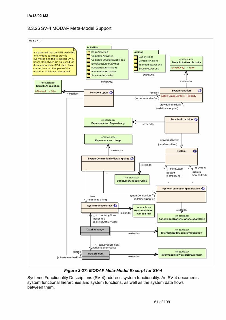
IA/13/02-M3
61 of 109
3.3.26 SV-4 MODAF Meta-Model Support
cd SV-4
System
SystemConnectionSpecification
Actions
BasicActionsCompleteActionsIntermediateActionsStructuredActions
(from UML)
Activ ities
BasicActivitiesCompleteActivitiesCompleteStructuredActivitiesExtraStructuredActivitiesFundamentalActivitiesIntermediateActivitiesStructuredActivities
(from UML)
«metaclass»StructuredClasses::Class
«metaclass»BasicActiv ities:
:ObjectFlow«metaclass»
AssociationClasses::AssociationClass
«metaclass»Dependencies::Usage
«metaclass»BasicActiv ities::Activ ity
isReadOnly: = false
SystemConnectionToFlowMapping
SystemFunction
systemUsageContext: Property
«metaclass»Dependencies::Dependency
FunctionProv ision
SystemFunctionFlow
It is assumed that the UML Activities and Actions packages provide everything needed to support SV-4, hence stereotypes are only used for those elements in SV-4 which have connections to other parts of the model, or which are constrained.
«metaclass»InformationFlows::InformationFlow
«metaclass»InformationFlows::InformationItem
DataExchange
DataElement
FunctionsUpon
«metaclass»Kernel::Association
isDerived: = false
subject
{subsets memberEnd}
function
{subsets memberEnd}
fromSystem1{subsetsmemberEnd}
*
toSystem1{subsetsmemberEnd}
*
«extends»
systemConnection 1{redefines supplier}
*
«extends»
flow{redefines client}
«extends»
«extends»
«extends»
«extends»
providedFunction{redefines supplier}
providingSystem
{redefines client}
«extends»
«extends»
realisingFlows1..*{redefinesrealizingActivityEdge}
conveyedElement1..*{redefines conveyed}
«extends»
Figure 3-27: MODAF Meta-Model Excerpt for SV-4 Systems Functionality Descriptions (SV-4) address system functionality. An SV-4 documents system functional hierarchies and system functions, as well as the system data flows between them.
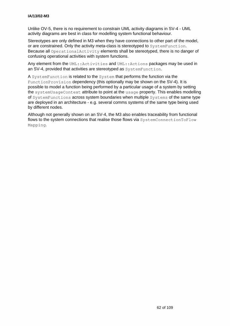
IA/13/02-M3
62 of 109
Unlike OV-5, there is no requirement to constrain UML activity diagrams in SV-4 - UML activity diagrams are best in class for modelling system functional behaviour.
Stereotypes are only defined in M3 when they have connections to other part of the model, or are constrained. Only the activity meta-class is stereotyped to SystemFunction. Because all OperationalActivity elements shall be stereotyped, there is no danger of confusing operational activities with system functions.
Any element from the UML::Activities and UML::Actions packages may be used in an SV-4, provided that activities are stereotyped as SystemFunction.
A SystemFunction is related to the System that performs the function via the FunctionProvision dependency (this optionally may be shown on the SV-4). It is possible to model a function being performed by a particular usage of a system by setting the systemUsageContext attribute to point at the usage property. This enables modelling of SystemFunctions across system boundaries when multiple Systems of the same type are deployed in an architecture - e.g. several comms systems of the same type being used by different nodes.
Although not generally shown on an SV-4, the M3 also enables traceability from functional flows to the system connections that realise those flows via SystemConnectionToFlow Mapping.
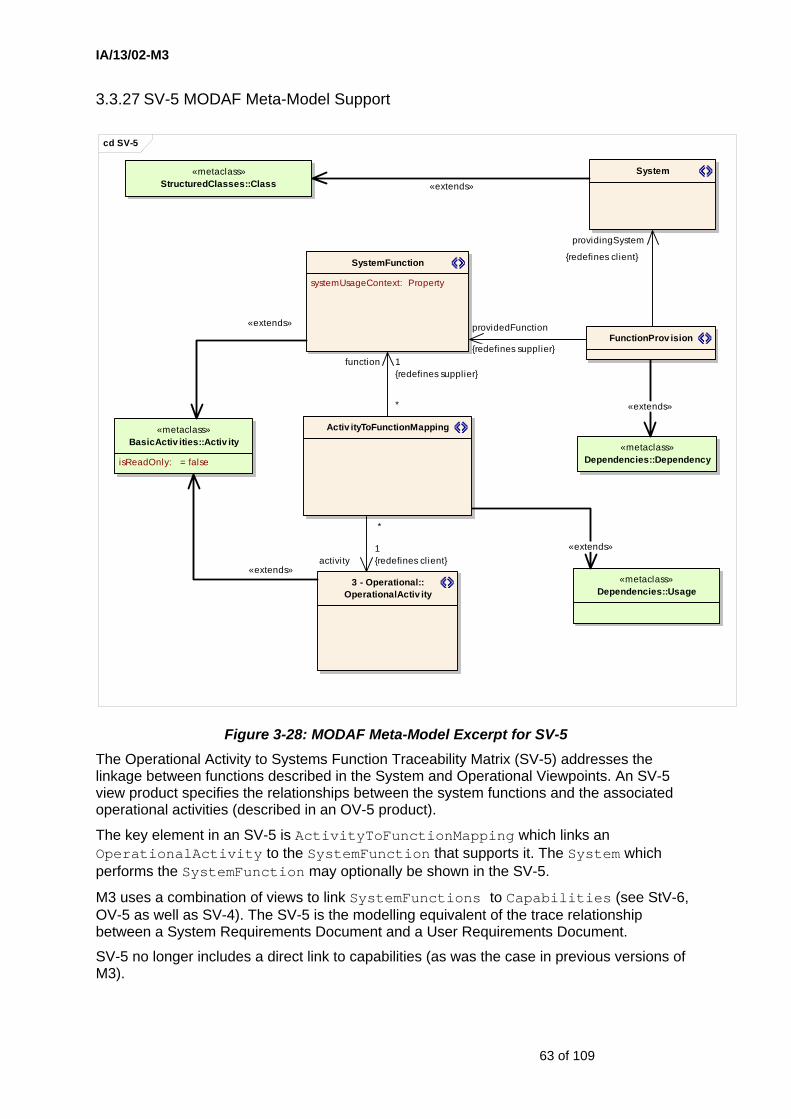
IA/13/02-M3
63 of 109
3.3.27 SV-5 MODAF Meta-Model Support
cd SV-5
«metaclass»BasicActiv ities::Activ ity
isReadOnly: = false
«metaclass»StructuredClasses::Class
3 - Operational::OperationalActiv ity
«metaclass»Dependencies::Usage
Activ ityToFunctionMapping
System
SystemFunction
systemUsageContext: Property
FunctionProv ision
«metaclass»Dependencies::Dependency
«extends»activity
1{redefines client}
*
«extends»
«extends»
function 1{redefines supplier}
*
«extends»
providingSystem
{redefines client}
providedFunction
{redefines supplier}
«extends»
Figure 3-28: MODAF Meta-Model Excerpt for SV-5 The Operational Activity to Systems Function Traceability Matrix (SV-5) addresses the linkage between functions described in the System and Operational Viewpoints. An SV-5 view product specifies the relationships between the system functions and the associated operational activities (described in an OV-5 product).
The key element in an SV-5 is ActivityToFunctionMapping which links an OperationalActivity to the SystemFunction that supports it. The System which performs the SystemFunction may optionally be shown in the SV-5.
M3 uses a combination of views to link SystemFunctions to Capabilities (see StV-6, OV-5 as well as SV-4). The SV-5 is the modelling equivalent of the trace relationship between a System Requirements Document and a User Requirements Document.
SV-5 no longer includes a direct link to capabilities (as was the case in previous versions of M3).
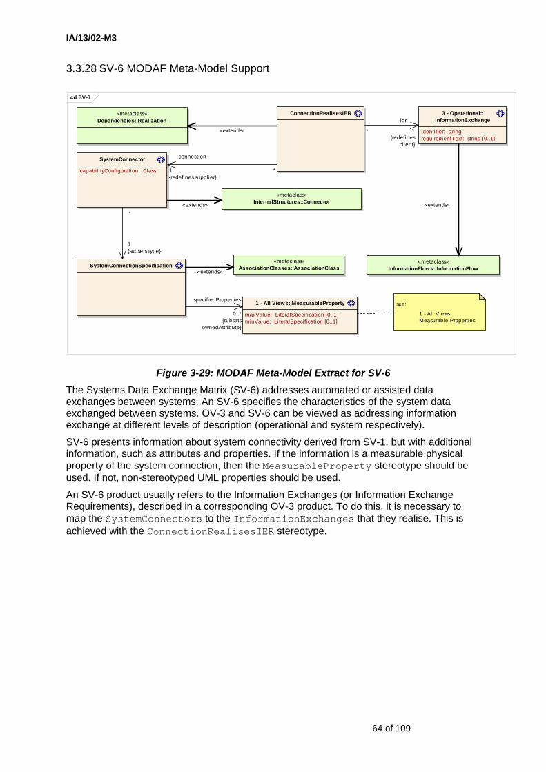
IA/13/02-M3
64 of 109
3.3.28 SV-6 MODAF Meta-Model Support
cd SV-6
«metaclass»InternalStructures::Connector
SystemConnector
capabilityConfiguration: Class
«metaclass»Dependencies::Realization
ConnectionRealisesIER
«metaclass»InformationFlows::InformationFlow
3 - Operational::InformationExchange
identifier: stringrequirementText: string [0..1]
«metaclass»AssociationClasses::AssociationClassSystemConnectionSpecification
1 - All Views::MeasurableProperty
maxValue: LiteralSpecification [0..1]minValue: LiteralSpecification [0..1]
see:
1 - All Views : Measurable Properties
connection
1{redefines supplier}
*
«extends»
«extends»
ier
1{redefines
client}
*
«extends»
specifiedProperties
0..*{subsets
ownedAttribute}
«extends»
1{subsets type}
*
Figure 3-29: MODAF Meta-Model Extract for SV-6 The Systems Data Exchange Matrix (SV-6) addresses automated or assisted data exchanges between systems. An SV-6 specifies the characteristics of the system data exchanged between systems. OV-3 and SV-6 can be viewed as addressing information exchange at different levels of description (operational and system respectively).
SV-6 presents information about system connectivity derived from SV-1, but with additional information, such as attributes and properties. If the information is a measurable physical property of the system connection, then the MeasurableProperty stereotype should be used. If not, non-stereotyped UML properties should be used.
An SV-6 product usually refers to the Information Exchanges (or Information Exchange Requirements), described in a corresponding OV-3 product. To do this, it is necessary to map the SystemConnectors to the InformationExchanges that they realise. This is achieved with the ConnectionRealisesIER stereotype.
IA/13/02-M3
65 of 109
3.3.29 SV-7 MODAF Meta-Model Support
cd SV-7
SystemAssemblyUsage
«metaclass»InternalStructures::Property
«metaclass»StructuredClasses::Class
System1 - All Views::MeasurableProperty
maxValue: LiteralSpecification [0..1]minValue: LiteralSpecification [0..1]
see:
1 - All Views : Measurable Properties
«extends»
*
parent
1{redefines
class}
physicalProperties
0..*{subsets ownedAttribute}
«extends»
child
1{redefines
type}
*
Figure 3-30: MODAF Meta-Model Extract for SV-7
The Systems Performance Parameters Matrix (SV-7) addresses measurable properties of systems. An SV-7 specifies the quantitative characteristics of systems and system hardware/software items, their interfaces (system data carried by the interface as well as communications link details that implement the interface), and their functions. It specifies the current performance parameters of each system, interface, or system function, and the expected or required performance parameters at specified times in the future. Performance parameters include all technical performance characteristics of systems for which requirements can be developed and specification defined.
SV-7 products build on the MODAF views that address structural decompositions (principally SV-1) by presenting more detailed information about systems and their sub-systems (e.g. hardware and software components), such as attributes and properties. If the information is a measurable physical property of the system or sub-system (e.g. response time), then the MeasurableProperty stereotype should be used. Otherwise, non-stereotyped UML properties should be used.
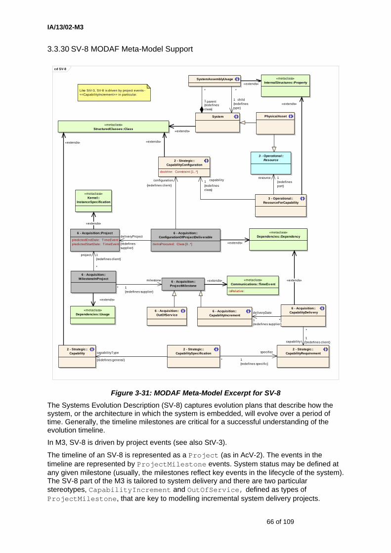
IA/13/02-M3
66 of 109
3.3.30 SV-8 MODAF Meta-Model Support
cd SV-8
«metaclass»InternalStructures::Property
2 - Strategic::CapabilityConfiguration
doctrine: Constraint [1..*]
«metaclass»StructuredClasses::Class
System
3 - Operational::ResourceForCapability
3 - Operational::Resource
PhysicalAsset
SystemAssemblyUsage
6 - Acquisition::Project
predictedEndDate: TimeEventpredictedStartDate: TimeEvent
6 - Acquisition::ConfigurationOfProjectDeliv erable
i temsProcured: Class [0..*]
6 - Acquisition::MilestoneInProject
6 - Acquisition::ProjectMilestone
6 - Acquisition::CapabilityIncrement
6 - Acquisition::OutOfServ ice
«metaclass»Dependencies::Dependency
«metaclass»Kernel::
InstanceSpecification
«metaclass»Dependencies::Usage
«metaclass»Communications::TimeEv ent
isRelative:
2 - Strategic::CapabilitySpecification
2 - Strategic::Capability
2 - Strategic::CapabilityRequirement
6 - Acquisition::CapabilityDeliv ery
Like StV-3, SV-8 is driven by project events - <<CapabilityIncrement>> in particular.
«extends»
capabilityType
{redefines general}
«extends»
resource 1{redefinespart}
*
parent1{redefinesclass}
«extends»
child1{redefinestype}
*
«extends»
*
specifier
1{redefines specific}
capabil ity1{redefinesclass}
configuration{redefines client}
*
deliveryDate
1{redefines supplier}
«extends»«extends»milestone
1{redefines supplier}
*
deliveryProject
{redefinessupplier}
*
capability1{redefines client}
«extends»
«extends»
project 1{redefines client}
*
«extends»
«extends»
Figure 3-31: MODAF Meta-Model Excerpt for SV-8 The Systems Evolution Description (SV-8) captures evolution plans that describe how the system, or the architecture in which the system is embedded, will evolve over a period of time. Generally, the timeline milestones are critical for a successful understanding of the evolution timeline.
In M3, SV-8 is driven by project events (see also StV-3).
The timeline of an SV-8 is represented as a Project (as in AcV-2). The events in the timeline are represented by ProjectMilestone events. System status may be defined at any given milestone (usually, the milestones reflect key events in the lifecycle of the system). The SV-8 part of the M3 is tailored to system delivery and there are two particular stereotypes, CapabilityIncrement and OutOfService, defined as types of ProjectMilestone, that are key to modelling incremental system delivery projects.

IA/13/02-M3
67 of 109
StV-3, SV-8 and SV-9 can be thought of as addressing capability evolution at different levels of description (capability, system and technology respectively). The formal links between these views are based on the links between the System and CapabilityConfiguration stereotypes (see Section 2).
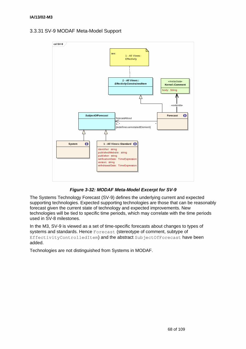
IA/13/02-M3
68 of 109
3.3.31 SV-9 MODAF Meta-Model Support
cd SV-9
System 1 - All Views::Standard
identifier: stringpublishedWebsite: stringpublisher: stringratificationDate: TimeExpressionversion: stringwithdrawalDate: TimeExpression
Forecast
«metaclass»Kernel::Comment
body: String
SubjectOfForecast
1 - All Views::EffectivityConstrainedItem
see:1 - All Views : Effectivity
*
forecastAbout
1..*{redefines annotatedElement}
«extends»
Figure 3-32: MODAF Meta-Model Excerpt for SV-9 The Systems Technology Forecast (SV-9) defines the underlying current and expected supporting technologies. Expected supporting technologies are those that can be reasonably forecast given the current state of technology and expected improvements. New technologies will be tied to specific time periods, which may correlate with the time periods used in SV-8 milestones.
In the M3, SV-9 is viewed as a set of time-specific forecasts about changes to types of systems and standards. Hence Forecast (stereotype of comment, subtype of EffectivityControlledItem) and the abstract SubjectOfForecast have been added.
Technologies are not distinguished from Systems in MODAF.
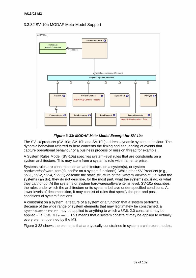
IA/13/02-M3
69 of 109
3.3.32 SV-10a MODAF Meta-Model Support
cd SV-10a
«metaclass»Kernel::Constraint
SystemConstraint
SubjectOfSystemConstraint
SystemPortSystemFunction
systemUsageContext: Property
System
SystemConnector
capabil ityConfiguration: Class
DataElementPhysicalAsset
PortType
DataExchange
{redefines constrainedElement}
«extends»
Figure 3-33: MODAF Meta-Model Excerpt for SV-10a The SV-10 products (SV-10a, SV-10b and SV-10c) address dynamic system behaviour. The dynamic behaviour referred to here concerns the timing and sequencing of events that capture operational behaviour of a business process or mission thread for example.
A System Rules Model (SV-10a) specifies system-level rules that are constraints on a system architecture. This may stem from a system’s role within an enterprise.
Systems rules are constraints on an architecture, on a system(s), or system hardware/software item(s), and/or on a system function(s). While other SV Products (e.g., SV-1, SV-2, SV-4, SV-11) describe the static structure of the System Viewpoint (i.e. what the systems can do), they do not describe, for the most part, what the systems must do, or what they cannot do. At the systems or system hardware/software items level, SV-10a describes the rules under which the architecture or its systems behave under specified conditions. At lower levels of decomposition, it may consist of rules that specify the pre- and post-conditions of system functions.
A constraint on a system, a feature of a system or a function that a system performs. Because of the wide range of system elements that may legitimately be constrained, a SystemConstraint may be applied to anything to which a UML 2.0 constraint may be applied - i.e. UML:Element. This means that a system constraint may be applied to virtually every element defined by the M3.
Figure 3-33 shows the elements that are typically constrained in system architecture models.
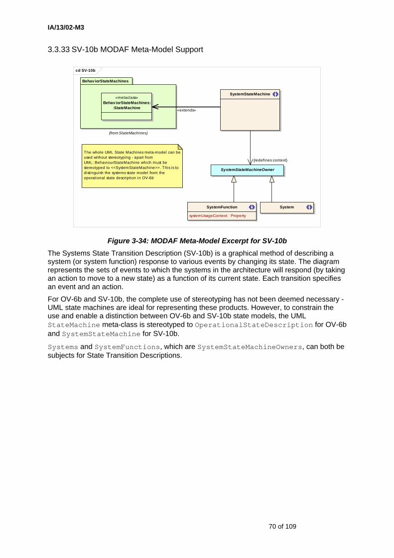
IA/13/02-M3
70 of 109
3.3.33 SV-10b MODAF Meta-Model Support
cd SV-10b
SystemFunction
systemUsageContext: Property
System
SystemStateMachine
Behav iorStateMachines
(from StateMachines)
«metaclass»Behav iorStateMachines:
:StateMachine
The whole UML State Machines meta-model can be used without stereotyping - apart from UML::BehaviourStateMachine which must be stereotyped to <<SystemStateMachine>>. This is to distinguish the systems state model from the operational state description in OV-6b
SystemStateMachineOwner
{redefines context}
«extends»
Figure 3-34: MODAF Meta-Model Excerpt for SV-10b The Systems State Transition Description (SV-10b) is a graphical method of describing a system (or system function) response to various events by changing its state. The diagram represents the sets of events to which the systems in the architecture will respond (by taking an action to move to a new state) as a function of its current state. Each transition specifies an event and an action.
For OV-6b and SV-10b, the complete use of stereotyping has not been deemed necessary - UML state machines are ideal for representing these products. However, to constrain the use and enable a distinction between OV-6b and SV-10b state models, the UML StateMachine meta-class is stereotyped to OperationalStateDescription for OV-6b and SystemStateMachine for SV-10b.
Systems and SystemFunctions, which are SystemStateMachineOwners, can both be subjects for State Transition Descriptions.

IA/13/02-M3
71 of 109
3.3.34 SV-10c MODAF Meta-Model Support
cd SV-10c
SystemPort
«metaclass»InternalStructures::ConnectableElement
SystemAssemblyUsage
SystemLifeLine
SystemInteractionSpecification
BasicInteractions
(from Interactions)
«metaclass»BasicInteractions::
Interaction
«metaclass»BasicInteractions::
Lifeline
SystemLifelineItem
*
1{redefines represents}
1{redefines l ifeline}
*{redefines interaction}
«extends»
«extends»
«extends»
Figure 3-35: MODAF Meta-Model Excerpt for SV-10c The Systems Event-Trace Description (SV-10c) provides a time-ordered examination of the system data elements exchanged between participating systems (external and internal), system functions, or human roles as a result of a thread within a mission. Each event-trace diagram will have an accompanying description that defines the mission thread. SV-10c in the System Viewpoint may reflect system-specific aspects or refinements of critical sequences of events described in the Operational Viewpoint.
For OV-6c and SV-10c, the complete use of stereotyping has not been deemed necessary - UML sequence (interaction) diagrams are ideal for representing these products. However, to constrain the use, and enable a distinction between OV-6c and SV-10c interaction models, the Interaction and Lifeline meta-classes are stereotyped.

IA/13/02-M3
72 of 109
3.3.35 SV-11 MODAF Meta-Model Support
cd SV-11
PhysicalDataModel
«metaclass»Kernel::
Generalization
isSubstitutable:
«metaclass»Kernel::Association
isDerived: = false
«metaclass»Kernel::Property
isDerived: = falseisDerivedUnion: = falseisReadOnly: = false
«metaclass»Kernel::Class
isAbstract: = false
«metaclass»Kernel::Package
5 - Technical Standards::EntityRelationship
5 - Technical Standards::Attribute
5 - Technical Standards::SubtypeRelationship
5 - Technical Standards::Entity
5 - Technical Standards::DataModel
DataElement
«metaclass»InformationFlows::
InformationItem
«extends»
«extends»
definedBy
{redefines represented}
«extends»
entities
0..*{redefines ownedMember}
1
supertype
1{redefines
general}
*
«extends»*
subtype
1{redefines
specific}
«extends»
1{subsets
ownedEnd}
1
1{subsets ownedAttribute}
*
«extends»
2{subsets
memberEnd}
1
Figure 3-36: MODAF Meta-Model Excerpt for SV-11 Physical Schema Products (SV-11) address the information perspective on the system architecture. An SV-11 defines the structure of the various kinds of system data that are utilised by the systems in the architecture.
Data models in MODAF have entity classes, relationships and attributes. Sub-typing (generalisation / specialisation) is also permitted.

IA/13/02-M3
73 of 109
3.3.36 TV-1 & TV-2 MODAF Meta-Model Support
cd TV-1&2
1 - All Views::Standard
identifier: stringpublishedWebsite: stringpublisher: stringratificationDate: TimeExpressionversion: stringwithdrawalDate: TimeExpression
«metaclass»StructuredClasses:
:Class
Protocol
«metaclass»Dependencies::Dependency
1 - All Views::ConformsTo
ProtocolStack «metaclass»InternalStructures:
:Property
lowerLayer{redefines part}
upperLayer{redefines class}
«extends»
appliedStandard
{redefines supplier}
«extends»
«extends»
Figure 3-37: MODAF Meta-Model Excerpt for TV-1 and TV-2 The Technical views address the technical systems-implementation standards upon which engineering specifications are based, common building blocks are established, and product lines are developed. TV-1 addresses standards profiles and TV-2 addresses the future forecast of standards (i.e. expected changes in the technology-related standards and conventions, which are documented in the TV-1). These have been treated together in M3.
The key stereotype required for TV-1 and TV-2 is Standard which can be applied throughout the architecture and listed in a TV-1 product. In general, Standards may be technical or relate to military operations or policy (only the former applies to the Technical views).
A Protocol is a special type of Standard that relates to SystemConnectors. Protocols may be nested (i.e. ProtocolStacks).
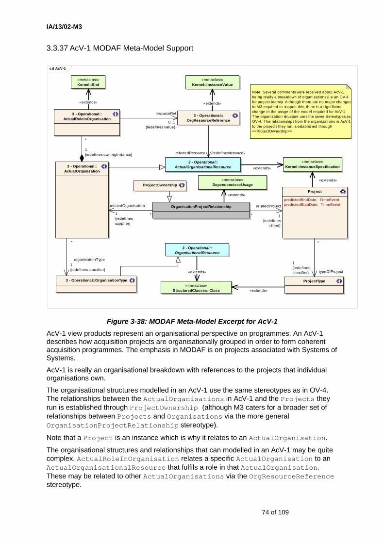
IA/13/02-M3
74 of 109
3.3.37 AcV-1 MODAF Meta-Model Support
cd AcV-1
3 - Operational::OrganisationalResource
3 - Operational::ActualOrganisationalResource3 - Operational::
ActualOrganisation
Project
predictedEndDate: TimeEventpredictedStartDate: TimeEvent
«metaclass»Kernel::InstanceSpecification
«metaclass»StructuredClasses::Class
«metaclass»Dependencies::Usage
OrganisationProjectRelationship
ProjectType3 - Operational::OrganisationType
«metaclass»Kernel::InstanceValue
«metaclass»Kernel::Slot
3 - Operational::ActualRoleInOrganisation
3 - Operational::OrgResourceReference
ProjectOwnership
Note: Several comments were received about AcV-1 being really a breakdown of organizations (i.e an OV-4 for project teams). Although there are no major changesto M3 required to support this, there is a significant change in the usage of the model required for AcV-1. The organization structure uses the same stereotypes as OV-4. The relationships from the organizations in AcV-1to the projects they run is established through <<ProjectOwnership>>
organisationType1{redefines classifier}
*
«extends»
«extends»
relatedProject
1{redefines
client}
*
*
typeOfProject
1{redefinesclassifier}
«extends»
«extends»
«extends»
«extends»
*
1{redefines owningInstance}
resourceRef
0..1{redefines value}
«extends»
referredResource {redefinesInstance}
relatedOrganisation
1{redefinessupplier}
*
Figure 3-38: MODAF Meta-Model Excerpt for AcV-1 AcV-1 view products represent an organisational perspective on programmes. An AcV-1 describes how acquisition projects are organisationally grouped in order to form coherent acquisition programmes. The emphasis in MODAF is on projects associated with Systems of Systems.
AcV-1 is really an organisational breakdown with references to the projects that individual organisations own.
The organisational structures modelled in an AcV-1 use the same stereotypes as in OV-4. The relationships between the ActualOrganisations in AcV-1 and the Projects they run is established through ProjectOwnership (although M3 caters for a broader set of relationships between Projects and Organisations via the more general OrganisationProjectRelationship stereotype).
Note that a Project is an instance which is why it relates to an ActualOrganisation.
The organisational structures and relationships that can modelled in an AcV-1 may be quite complex. ActualRoleInOrganisation relates a specific ActualOrganisation to an ActualOrganisationalResource that fulfils a role in that ActualOrganisation. These may be related to other ActualOrganisations via the OrgResourceReference stereotype.
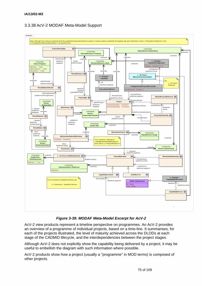
IA/13/02-M3
75 of 109
3.3.38 AcV-2 MODAF Meta-Model Support
cd AcV-2
ThreadInProject
«metaclass»StructuredClasses::Class
«metaclass»Dependencies::Usage
MilestoneInProject
1 - All Views::ISO8601DateTime«metaclass»SimpleTime::
TimeExpression
firstTime: = True
«metaclass»Communications::TimeEvent
isRelative:
«metaclass»Dependencies::Dependency
ProjectThreadType
ProjectRelationship
«metaclass»Kernel::Slot
«metaclass»Kernel::InstanceValue
«metaclass»Kernel::
InstanceSpecification
RelatedProjectReference
Project
predictedEndDate: TimeEventpredictedStartDate: TimeEvent
WorkstreamStatusAtMilestone
milestone: TimeEvent
MilestoneRelationshipProjectMilestone
ProjectType
«metaclass»InternalStructures::Property
ConfigurationOfProjectDeliv erable
i temsProcured: Class [0..*]
2 - Strategic::CapabilityConfiguration
doctrine: Constraint [1..*]
Note: Although AcV-2 does not explicitly show the capabil ities being delivered by a project, it may be useful to embellish the diagram with such information. Hence <<ProjectAimsToDeliver>> and <<ConfigurationOfProjectDeliverable>> are specified here.
1 - All Views::EffectivityConstrainedItem
Workstream
«metaclass»Kernel::Property
isDerived: = falseisDerivedUnion: = falseisReadOnly: = false
ThreadStatusIndicator
«metaclass»Kernel::
Enumeration
«metaclass»Kernel::
EnumerationLiteral
ThreadStatuses
ThreadStatus
ThreadValue
CapabilityIncrement OutOfServ ice
see:1 - All Views : Effectivity
2 - Strategic::CapabilityRequirement
SysML::Requirement
ID: StringText: String
CapabilityDeliv ery
ProjectAimsToDeliv er
2 - Strategic::Capability
The "milestone" attributes of <<WorkstreamStatusAtMilestone>> shall refer to a <<ProjectMilestone>>
For an overview of capabil ity delivery, see:
0 - Introduction : Capability Delivery
statusIndicator 1{subsets /attribute}
relatedProject 1{redefinesvalue}*
«extends»
*
deliveryDate 1{redefines supplier}
thread1{redefines type}
*
«extends»
«extends»
«extends»1{redefines when}
*
«extends»
«extends»
projectWithThread
1{redefinesclassifier}
*
«extends»
«extends»
«extends»
milestone1{redefines supplier}
*
toMileStone1{redefines supplier}
*
fromMilestone1{redefines client}
*
«extends»
«extends»
workstream{redefinesclassifier}
status{redefines value}
definingIndicator{redefines definingFeature}
project 1{redefines client}
*
*typeOfProject1{redefinesclassifier}
referredProject
1{redefines instance}
*
owningProject
1{redefines owninginstance}
*
*
capabil ity 1{redefines client}
«extends»
statuses1{redefinesdatatype} «extends»
statuses{redefinesownedLiteral}
«extends»
«extends»
value{redefinesinstance}
«extends»
«extends»
«extends»
deliveryProject{redefines client}
aim{redefines supplier}
«extends»
configuration{redefines client}«extends»
«extends»
threadType{redefinesclassifier}
deliveryProject{redefines supplier}
Figure 3-39: MODAF Meta-Model Excerpt for AcV-2 AcV-2 view products represent a timeline perspective on programmes. An AcV-2 provides an overview of a programme of individual projects, based on a time-line. It summarises, for each of the projects illustrated, the level of maturity achieved across the DLODs at each stage of the CADMID lifecycle, and the interdependencies between the project stages.
Although AcV-2 does not explicitly show the capability being delivered by a project, it may be useful to embellish the diagram with such information where possible.
AcV-2 products show how a project (usually a "programme" in MOD terms) is composed of other projects.

IA/13/02-M3
76 of 109
The meta-model extract for AcV-2 has been extended to include tighter integration with the Strategic views by means of the ConfigurationOfProjectDeliverable dependency relationship. See Figure 2-7. Projects are now viewed as delivering capability not just systems.
The Project instances in an AcV-2 product must have a predictedStartDate and predictedEndDate which shall refer to ISO8601DateTime TimeEvents. This sets the timeline for each project (displayed as a Gantt line in AcV-2 products).
Each project is typed by a ProjectType (usually "Procurement Project") which has a number of ProjectThreadType classes (usually MOD Lines of Defence, though any other method of defining threads of a project is acceptable).
Each ProjectType has a typical set of ProjectThreadTypes. Actual projects will have Workstreams. These are instantiations of ProjectThreadTypes. A Workstream might deliver a System (or a system component) or a Competence, for example.
Each project may have milestones (ProjectMilestone) related to the project via MilestoneInProject. There may be dependency relationships between milestones (MilestoneRelationship).
CapabilityIncrement and OutOfService have been added as subclasses of ProjectMilestone. The reason for this is that these specific events inform other key areas of MODAF such as StV-3, StV-5, and SV-8.
It is also possible to specify the status of the project workstreams at each milestone (WorkstreamStatusAtMilestone)which is represented on an AcV-2 as the traffic-light pie chart on each milestone. The enumerated set of ThreadStatuses constrains the ThreadValues.
The milestone attribute within an instance of a WorkstreamStatusAtMilestone stereotype must be set to one of the ProjectMilestones.

IA/13/02-M3
77 of 109
3.4 Proposed Extensions to Core M3
3.4.1 Proposed MODAF Meta-Model Support for Effects Based Operations
cd Effects
Behav iorStateMachines
ConnectionPointReferenceFinalStatePseudostatePseudostateKindRegionStateStateMachineTimeEventTransitionTransitionKindVertex
(from StateMachines)
2 - Strategic::Effect
«metaclass»BasicActiv ities::Activ ity
isReadOnly: = false
GeneralisationOfEffect 3 - Operational::RealisationOfEffect
3 - Operational::OperationalActiv ity
«metaclass»Dependencies::Realization
ResultOfEffect
«metaclass»Dependencies::Dependency
«metaclass»PowerTypes::GeneralizationSet
isCovering: isDisjoint:
«metaclass»PowerTypes::Generalization
EffectsTaxonomy
EffectsTaxonomyMember
3 - Operational::Node
3 - Operational::NodeConnectionType
«metaclass»AssociationClasses:
:AssociationClass
«metaclass»StructuredClasses:
:Class
3 - Operational::NodeAffectsNode
effect: Realization
constraints{effect.effector :=: fromNode}
There is a movement towards an "effects based" approach to operational planning and analysis. At the time of publishing this model, there was no agreed MOD approach to Effects-Based Operations (EBO). This model should be considered a "straw-man" for tool vendors wishing to investigate the possibili ties. There are no corresponding MODAF views on v1.0 of MODAF.
RequiredEffect
2 - Strategic::Capability
«metaclass»Behav iorStateMachines::State
«metaclass»BasicBehav iors::OpaqueBehav ior
body: String [1..*] {ordered}language: String [0..*] {ordered}
Subject to Change
{redefines generalization}
{redefines general}
«extends»
{redefines specific}
action{redefines cl ient}
effectAchieved
{redefinessupplier}
«extends»
«extends»
result {redefines supplier}
«extends»
effect
{redefines client}
«extends»
taxonomy {redefines powertype}
toNode1{subsets /endType}
*
fromNode1{subsets/endType}
*
«extends»
«extends»
«extends»
effect
{redefines supplier}
capabil i ty {redefines client}
«extends»
«extends»
Figure 3-40: Proposed MODAF Meta-Model Excerpt for Effects See Section 6.1.7.
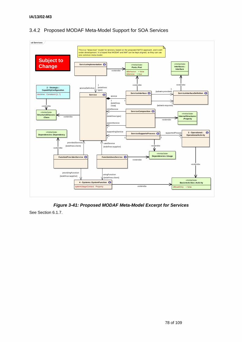
IA/13/02-M3
78 of 109
3.4.2 Proposed MODAF Meta-Model Support for SOA Services
cd Serv ices
«metaclass»InternalStructures:
:Property
Serv iceComposition
Serv iceSupportsProcess
«metaclass»Interfaces::
Interface
Serv iceInterfaceDefinitionServ iceInterface
Serv iceImplementation
Serv ice
«metaclass»Ports::Port
isBehavior: = falseisService: = true
«metaclass»Dependencies::Usage
«metaclass»StructuredClasses:
:Class
«metaclass»BasicActiv ities::Activ ity
isReadOnly: = false
3 - Operational::OperationalActiv ity
2 - Strategic::CapabilityConfiguration
doctrine: Constraint [1..*]
4 - Systems::SystemFunction
systemUsageContext: Property
«metaclass»Dependencies::Dependency
FunctionProv idesServ ice
This is a "straw-man" model for services, based on the proposed NATO approach, and is sti l l under development. It is hoped that MODAF and NAF can be kept aligned, so they can use one common meta-model.
Subject to Change
FunctionUsesServ ice
supportingService
1 1
«extends»
providedService
{redefines client}
providingFunction
{redefines supplier}
supportedProcess
11
«extends»
«extends»
«extends»
parentService
1
usingFunction{redefines client}
service
1{redefinesclass}
1
serviceDefinition1{redefinestype}
«extends»
«extends» «extends»
1{subsets provided}
1{subsets required}
«extends»
«extends»
«extends»
«extends»
usedService
{redefines supplier}
childService
1{redefines type}
Figure 3-41: Proposed MODAF Meta-Model Excerpt for Services See Section 6.1.7.
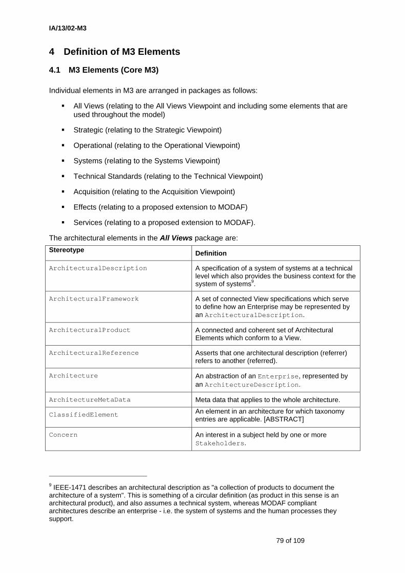
IA/13/02-M3
79 of 109
4 Definition of M3 Elements
4.1 M3 Elements (Core M3)
Individual elements in M3 are arranged in packages as follows:
All Views (relating to the All Views Viewpoint and including some elements that are used throughout the model)
Strategic (relating to the Strategic Viewpoint)
Operational (relating to the Operational Viewpoint)
Systems (relating to the Systems Viewpoint)
Technical Standards (relating to the Technical Viewpoint)
Acquisition (relating to the Acquisition Viewpoint)
Effects (relating to a proposed extension to MODAF)
Services (relating to a proposed extension to MODAF).
The architectural elements in the All Views package are: Stereotype Definition
ArchitecturalDescription A specification of a system of systems at a technical level which also provides the business context for the system of systems9.
ArchitecturalFramework A set of connected View specifications which serve to define how an Enterprise may be represented by an ArchitecturalDescription.
ArchitecturalProduct A connected and coherent set of Architectural Elements which conform to a View.
ArchitecturalReference Asserts that one architectural description (referrer) refers to another (referred).
Architecture An abstraction of an Enterprise, represented by an ArchitectureDescription.
ArchitectureMetaData Meta data that applies to the whole architecture.
ClassifiedElement An element in an architecture for which taxonomy entries are applicable. [ABSTRACT]
Concern An interest in a subject held by one or more Stakeholders.
9 IEEE-1471 describes an architectural description as "a collection of products to document the architecture of a system". This is something of a circular definition (as product in this sense is an architectural product), and also assumes a technical system, whereas MODAF compliant architectures describe an enterprise - i.e. the system of systems and the human processes they support.
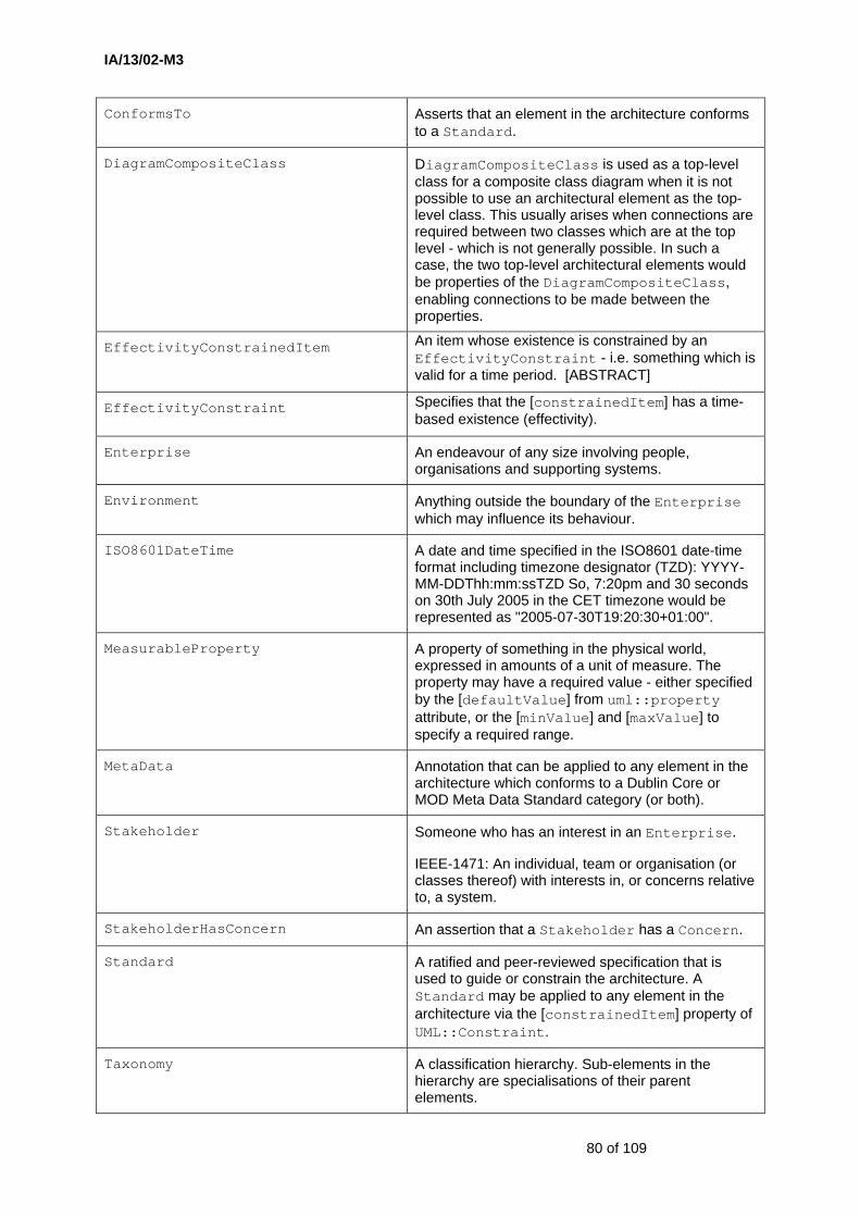
IA/13/02-M3
80 of 109
ConformsTo Asserts that an element in the architecture conforms to a Standard.
DiagramCompositeClass DiagramCompositeClass is used as a top-level class for a composite class diagram when it is not possible to use an architectural element as the top-level class. This usually arises when connections are required between two classes which are at the top level - which is not generally possible. In such a case, the two top-level architectural elements would be properties of the DiagramCompositeClass, enabling connections to be made between the properties.
EffectivityConstrainedItem An item whose existence is constrained by an EffectivityConstraint - i.e. something which is valid for a time period. [ABSTRACT]
EffectivityConstraint Specifies that the [constrainedItem] has a time-based existence (effectivity).
Enterprise An endeavour of any size involving people, organisations and supporting systems.
Environment Anything outside the boundary of the Enterprise which may influence its behaviour.
ISO8601DateTime A date and time specified in the ISO8601 date-time format including timezone designator (TZD): YYYY-MM-DDThh:mm:ssTZD So, 7:20pm and 30 seconds on 30th July 2005 in the CET timezone would be represented as "2005-07-30T19:20:30+01:00".
MeasurableProperty A property of something in the physical world, expressed in amounts of a unit of measure. The property may have a required value - either specified by the [defaultValue] from uml::property attribute, or the [minValue] and [maxValue] to specify a required range.
MetaData Annotation that can be applied to any element in the architecture which conforms to a Dublin Core or MOD Meta Data Standard category (or both).
Stakeholder Someone who has an interest in an Enterprise.
IEEE-1471: An individual, team or organisation (or classes thereof) with interests in, or concerns relative to, a system.
StakeholderHasConcern An assertion that a Stakeholder has a Concern.
Standard A ratified and peer-reviewed specification that is used to guide or constrain the architecture. A Standard may be applied to any element in the architecture via the [constrainedItem] property of UML::Constraint.
Taxonomy A classification hierarchy. Sub-elements in the hierarchy are specialisations of their parent elements.

IA/13/02-M3
81 of 109
TimePeriod A period of time, defined by start and end dates - sometimes termed an "Epoch" in the MOD. Time periods may overlap.
View A specification of a way to present an aspect of the architecture. Views are defined with one or more purposes in mind - e.g. showing the logical topology of the enterprise, describing a process model, defining a data model, etc.
The architectural elements in the Strategic package are:
Stereotype Definition
Capability A high level specification of the enterprise's ability.
CapabilityComposition A parent-child relationship between two capabilities - i.e. the relationship indicates one capability (child) is a sub-capability of the other (parent). Although the MOD tends to work in terms of capabilities and capability functions, it is not always apparent that there is any difference between them other than their relative positions in a capability taxonomy, which is specified by the CapabilityComposition relationship.
CapabilityConfiguration A combination of organisational aspects (with their competencies) and equipment that combine to provide a capability. A CapabilityConfiguration is a physical asset or organisation configured to provide a capability, and must be guided by [doctrine] which may take the form of Standard or OperationalConstraint stereotypes.
CapabilityContributesToVision An assertion that a Capability, when implemented, contributes to the realisation of a CapabilityVision.
CapabilityDependence A relationship which asserts that a capability (toCapability) is dependent on another (fromCapability) capability in the context of an overall capability.
Note: this dependency relates parts (i.e. properties) in a composite class diagram, therefore each dependency is in context of the parent composite class.

IA/13/02-M3
82 of 109
CapabilityRequirement A time-dependent requirement for a Capability.
Note 1: The purpose of this being time-dependent is to provide a class to which required metrics for a Capability may be assigned for a given period of time, represented as MeasurableProperties (via the capabilityMetrics attribute).
Note 2: that some capabilities might be called "capability functions" - MODAF does not distinguish between capability functions and capabilities, other than by virtue of their position in a hierarchy, defined by CapabilityComposition.
CapabilitySpecialisation Asserts that one RequiredCapability is a special
case of the other.
CapabilitySpecification Asserts that a CapabilityRequirement specifies the required performance of a Capability.
CapabilitySupportsTask Asserts that a Capability supports the execution of an EnduringTask.
CapabilityVision The overall aims of an Enterprise over a given period of time.
Effect An action that brings about change in the behaviour or state of something.
Note: an effect may be direct - e.g. an attack with kinetic weapons, or indirect: through psychological, diplomatic, or economic means - i.e. anything that can be used to change the behaviour or state of another node.10
EnduringTask A type of behaviour recognised by an enterprise as being essential to achieving its goals - i.e. a strategic specification of what the enterprise does.
Note: This is equivalent to a task in an essential task list (JETL).
EnterpriseGoal A specific, required objective of the enterprise that the architecture represents.
Note: Benefits of achieving the goal are presented as a list of textual items.
GoalOfVision Asserts that a Goal is part of a CapabilityVision.
TaskAchievesGoal An assertion that an EnduringTask can deliver the outcome of an EnterpriseGoal.
10 Reference: "Effects-Based Operations", Paul Davis, Rand Research, ISBN: 0-8330-3108-2
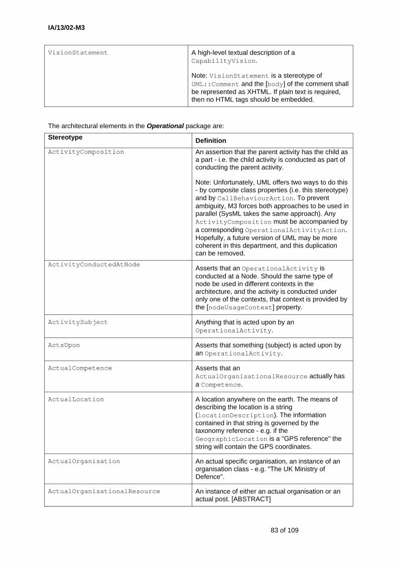
IA/13/02-M3
83 of 109
VisionStatement A high-level textual description of a CapabilityVision.
Note: VisionStatement is a stereotype of UML::Comment and the [body] of the comment shall be represented as XHTML. If plain text is required, then no HTML tags should be embedded.
The architectural elements in the Operational package are:
Stereotype Definition ActivityComposition An assertion that the parent activity has the child as
a part - i.e. the child activity is conducted as part of conducting the parent activity.
Note: Unfortunately, UML offers two ways to do this - by composite class properties (i.e. this stereotype) and by CallBehaviourAction. To prevent ambiguity, M3 forces both approaches to be used in parallel (SysML takes the same approach). Any ActivityComposition must be accompanied by a corresponding OperationalActivityAction. Hopefully, a future version of UML may be more coherent in this department, and this duplication can be removed.
ActivityConductedAtNode Asserts that an OperationalActivity is conducted at a Node. Should the same type of node be used in different contexts in the architecture, and the activity is conducted under only one of the contexts, that context is provided by the [nodeUsageContext] property.
ActivitySubject Anything that is acted upon by an OperationalActivity.
ActsUpon Asserts that something (subject) is acted upon by an OperationalActivity.
ActualCompetence Asserts that an ActualOrganisationalResource actually has a Competence.
ActualLocation A location anywhere on the earth. The means of describing the location is a string (locationDescription). The information contained in that string is governed by the taxonomy reference - e.g. if the GeographicLocation is a "GPS reference" the string will contain the GPS coordinates.
ActualOrganisation An actual specific organisation, an instance of an organisation class - e.g. "The UK Ministry of Defence".
ActualOrganisationalResource An instance of either an actual organisation or an actual post. [ABSTRACT]

IA/13/02-M3
84 of 109
Stereotype Definition
ActualOrganisationalRelationship A relationship between two actual specific parts of an organisation.
Note: the TypicalOrganisationRelationship which is realised by the ActualOrganisationRelationship is referred to via the typicalRelationship attribute.
ActualPost An actual, specific post, an instance of a Post class - e.g. "CSIS IPT Leader".
ActualRoleInOrganisation Relates an actual specific organisation to an actual specific organisational resource that fulfils a role in that organisation.
AspectOfHLOC A temporal part of the high level operational concept, optionally specifying the type of location for which the metrics are valid.
Example: The metrics for desert warfare in Epoch 1 are different to those in Epoch 2. The metrics for jungle warfare in Epoch 2 are different to those for desert warfare in Epoch 2.
Note: The purpose of this element is to provide a spatio-temporal container for the operational performance metrics.
Competence A specific set of abilities defined by knowledge, skills and attitude.
ConceptDescription A textual representation of a HighLevelOperationalConcept.
ConceptItem An item which may feature in a high level operational concept. [ABSTRACT]
ContributionToTask Asserts that an OperationalActivity contributes to the execution of an EnduringTask.
HighLevelOperationalConcept A generalized model for operations.
Note: a background image may be associated with the HLOC, which is referred to by the backgroundImageURL attribute. Scaling information is also provided about the image, so that when an ItemInConcept is shown in the diagram, it can be properly located and scaled. No units are specified, but the same length unit shall be used throughout a single OV-1a product.
HLOCAspect Asserts that an AspectOfHLOC is a spatio-temporal part of a HighLevelOperationalConcept.

IA/13/02-M3
85 of 109
Stereotype Definition
IDEF0FlowEnd A control or mechanism pin on an activity. [ABSTRACT]
Note: DoDAF's OV-5 is strongly oriented through CADM. For compatibillity with DoDAF, MODAF needs to be able to deal with control and mechanism concepts.
InfoElementInFlow Asserts that an information element is passed along the flow between activities.
InformationElement A formalized representation of information subject to an operational process.
InformationExchange A specification of the information that is to be exchanged. An InformationExchange must have a unique identifier.
Note: additional information about the requirements for the InformationExchange may be provided by the requirementText attribute
InformationExchangeMessage A message representing the exchange of information defined by an InformationExchange.
ItemInConcept A relationship which asserts that a ConceptItem forms part of the high level operational concept .
LocationType A general specification of the surroundings / scenario in which an operation may take place.
Examples: "desert", "arctic", "at sea".
LogicalDataModel A LogicalDataModel is a specification of business information requirements as a formal data structure, where relationships and classes (entities) are used to specify the logic which underpins the information.
Mission A purpose to which a person, organisation or autonomous system is tasked.
Needline A relationship specifying the need to exchange information between nodes, uniquely identified in context of the OV-2 product by its needlineNumber.
Note: The Needline does not indicate how the transfer is implemented.
Node A logical entity which creates, consumes or manipulates information.

IA/13/02-M3
86 of 109
Stereotype Definition
NodeAffectsNode An assertion that one Node brings an Effect to bear on another Node.
Note 1: The effect that is brought to bear is a related via the effect attribute which shall refer to a RealisationOfEffect. In other words, the effect is realised by an operational activity taking place at the from Node.
Note 2: This would be displayed on an OV-2 product as a NodeConnector typed as a NodeAffectsNode.
NodeAssemblyUsage Used to link a parent node to its sub-nodes. Only NodeAssemblyUsage may be used to represent a node-subnode relationship.
NodeConnectionEnd The end of a connector between nodes - i.e. for Needline and NodeConnector.
NodeConnectionType A type of connection between nodes. In most cases this is not required - NodeConnectors and Needlines need not be typed.
NodeConnector Asserts that a physical flow exists or is required between nodes (e.g. flows of people, materiel, or energy).
NodeProvidesControlOrMechanism An assertion that a Node provides the mechanism or control for an activity.
OpActivityControlPin A port for things flowing into an activity which constrain or govern how the activity is performed.
OpActivityInputPin A port for flows that feed into an activity.
OpActivityMechanismPin A port for things flowing into an activity which support or perform the activity.
OpActivityOutputPin A port for flows that leave an activity.
OperationalActivity A process carried out by a person or organisation - i.e. not an automated function.
OperationalActivityAction Used to relate an OperationalActivity to its sub-activities.
Note 1: An OperationalActivityAction will be created for every OperationalActivity to provide a way to manage sub-activities, and to allow flows between activities.
Note 2: See also ActivityComposition.
Note 3: Also provides a means for attaching information (properties) to an activity.
OperationalActivityFlow A flow of information, energy or materiel from one activity to another.
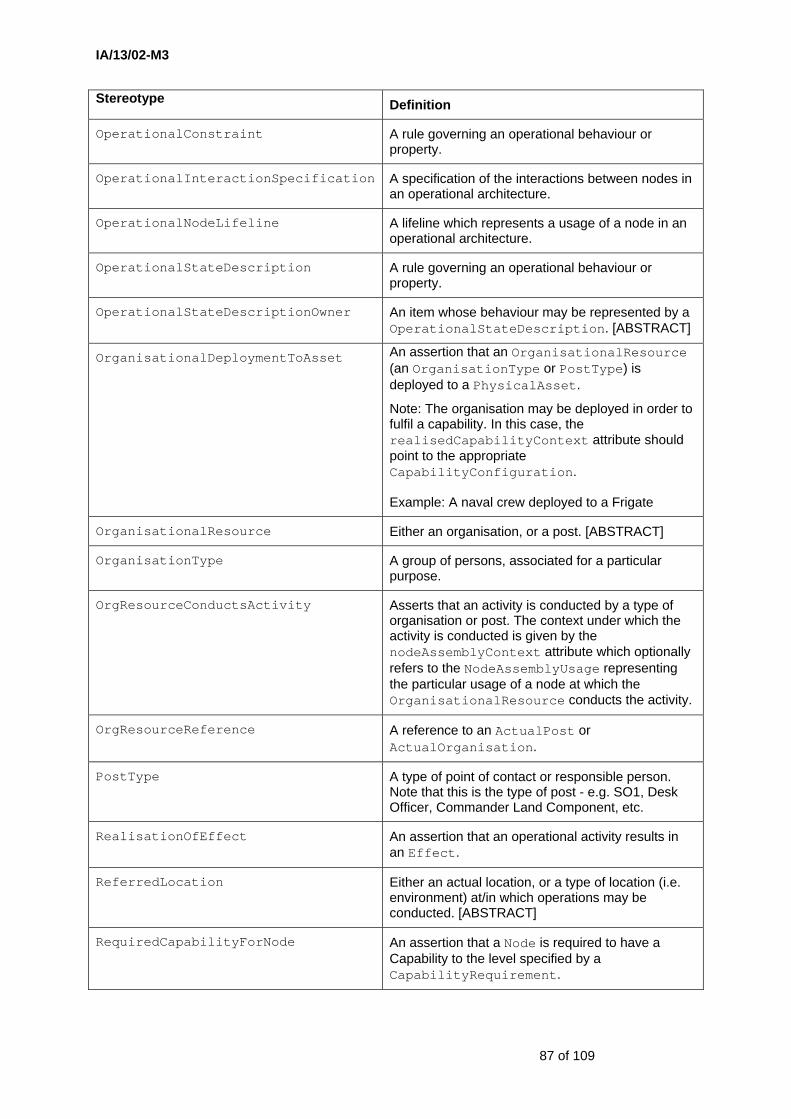
IA/13/02-M3
87 of 109
Stereotype Definition
OperationalConstraint A rule governing an operational behaviour or property.
OperationalInteractionSpecification A specification of the interactions between nodes in an operational architecture.
OperationalNodeLifeline A lifeline which represents a usage of a node in an operational architecture.
OperationalStateDescription A rule governing an operational behaviour or property.
OperationalStateDescriptionOwner An item whose behaviour may be represented by a OperationalStateDescription. [ABSTRACT]
OrganisationalDeploymentToAsset An assertion that an OrganisationalResource (an OrganisationType or PostType) is deployed to a PhysicalAsset.
Note: The organisation may be deployed in order to fulfil a capability. In this case, the realisedCapabilityContext attribute should point to the appropriate CapabilityConfiguration.
Example: A naval crew deployed to a Frigate
OrganisationalResource Either an organisation, or a post. [ABSTRACT]
OrganisationType A group of persons, associated for a particular purpose.
OrgResourceConductsActivity Asserts that an activity is conducted by a type of organisation or post. The context under which the activity is conducted is given by the nodeAssemblyContext attribute which optionally refers to the NodeAssemblyUsage representing the particular usage of a node at which the OrganisationalResource conducts the activity.
OrgResourceReference A reference to an ActualPost or ActualOrganisation.
PostType A type of point of contact or responsible person. Note that this is the type of post - e.g. SO1, Desk Officer, Commander Land Component, etc.
RealisationOfEffect An assertion that an operational activity results in an Effect.
ReferredLocation Either an actual location, or a type of location (i.e. environment) at/in which operations may be conducted. [ABSTRACT]
RequiredCapabilityForNode An assertion that a Node is required to have a Capability to the level specified by a CapabilityRequirement.

IA/13/02-M3
88 of 109
Stereotype Definition
RequiredCompetence Asserts that a RoleInOrganisation requires an OrganisationalResource that has the specified Competence.
RequiredNodeLocation Relates a node to a location to assert that the operational node is required to be situated at that location.
Resource A PhysicalAsset or OrganisationalResource that can contribute towards fulfilling a capability. [ABSTRACT]
ResourceForCapability Asserts that a resource (a PhysicalAsset, OrganisationType or PostType) contributes towards achieving a CapabilityConfiguration.
ResourceHasCompetence Asserts that an OrganisationalResource typically has a Competence.
RoleInOrganisation Defines a role in an organisation which is fulfilled by a post or by a sub-ordinate organisation. The role may or may not be fulfilled (i.e. roleProvider is null) - e.g. it may be a vacant post.
SubjectOfOperationalConstraint An element of the architecture that may be subject to an operational constraint. [ABSTRACT]
TypicalOrganisationRelationship An assertion that two instances of OrganisationType typically are related.
Example: Manufacturers and parts suppliers are typically related.
Note: It is also possible to specify that the relationship only exists in a certain context (i.e. when the organisations play a certain role). For example, a company's design department may second staff to a government department when both those departments are in the same integrated project team. This is achieved by setting the [fromOrgRole] and [toOrgRole] attributes to properties that are stereotyped as RoleInOrganisation.
The architectural elements in the Systems package are:
Stereotype Definition ActivityToFunctionMapping Asserts that a SystemFunction (at least in part)
performs or assists in the conducting of an OperationalActivity.
CapabilityProvider A means of fulfilling a required capability. [ABSTRACT]
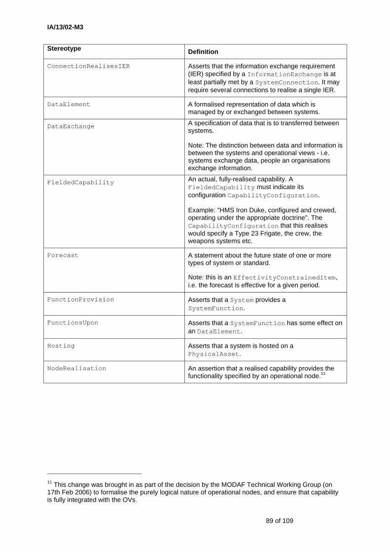
IA/13/02-M3
89 of 109
Stereotype Definition
ConnectionRealisesIER Asserts that the information exchange requirement (IER) specified by a InformationExchange is at least partially met by a SystemConnection. It may require several connections to realise a single IER.
DataElement A formalised representation of data which is managed by or exchanged between systems.
DataExchange A specification of data that is to transferred between systems.
Note: The distinction between data and information is between the systems and operational views - i.e. systems exchange data, people an organisations exchange information.
FieldedCapability An actual, fully-realised capability. A FieldedCapability must indicate its configuration CapabilityConfiguration.
Example: "HMS Iron Duke, configured and crewed, operating under the appropriate doctrine". The CapabilityConfiguration that this realises would specify a Type 23 Frigate, the crew, the weapons systems etc.
Forecast A statement about the future state of one or more types of system or standard.
Note: this is an EffectivityConstrainedItem, i.e. the forecast is effective for a given period.
FunctionProvision Asserts that a System provides a SystemFunction.
FunctionsUpon Asserts that a SystemFunction has some effect on an DataElement.
Hosting Asserts that a system is hosted on a PhysicalAsset.
NodeRealisation An assertion that a realised capability provides the functionality specified by an operational node.11
11 This change was brought in as part of the decision by the MODAF Technical Working Group (on 17th Feb 2006) to formalise the purely logical nature of operational nodes, and ensure that capability is fully integrated with the OVs.
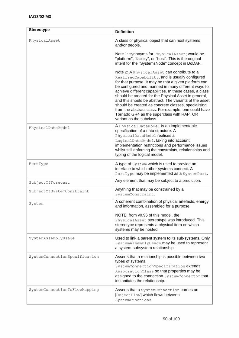
IA/13/02-M3
90 of 109
Stereotype Definition
PhysicalAsset A class of physical object that can host systems and/or people.
Note 1: synonyms for PhysicalAsset; would be "platform", "facility", or "host". This is the original intent for the "SystemsNode" concept in DoDAF.
Note 2: A PhysicalAsset can contribute to a RealisedCapability, and is usually configured for that purpose. It may be that a given platform can be configured and manned in many different ways to achieve different capabilities. In these cases, a class should be created for the Physical Asset in general, and this should be abstract. The variants of the asset should be created as concrete classes, specialising from the abstract class. For example, one could have Tornado GR4 as the superclass with RAPTOR variant as the subclass.
PhysicalDataModel A PhysicalDataModel is an implementable specification of a data structure. A PhysicalDataModel realises a LogicalDataModel, taking into account implementation restrictions and performance issues whilst still enforcing the constraints, relationships and typing of the logical model.
PortType A type of System which is used to provide an interface to which other systems connect. A PortType may be implemented as a SystemPort.
SubjectOfForecast Any element that may be subject to a prediction.
SubjectOfSystemConstraint Anything that may be constrained by a SystemConstraint.
System A coherent combination of physical artefacts, energy and information, assembled for a purpose.
NOTE: from v0.96 of this model, the PhysicalAsset stereotype was introduced. This stereotype represents a physical item on which systems may be hosted.
SystemAssemblyUsage Used to link a parent system to its sub-systems. Only SystemAssemblyUsage may be used to represent a system-subsystem relationship.
SystemConnectionSpecification Asserts that a relationship is possible between two types of systems. SystemConnectionSpecification extends AssociationClass so that properties may be assigned to the connection SystemConnector that instantiates the relationship.
SystemConnectionToFlowMapping Asserts that a SystemConnection carries an [ObjectFlow] which flows between SystemFunctions.
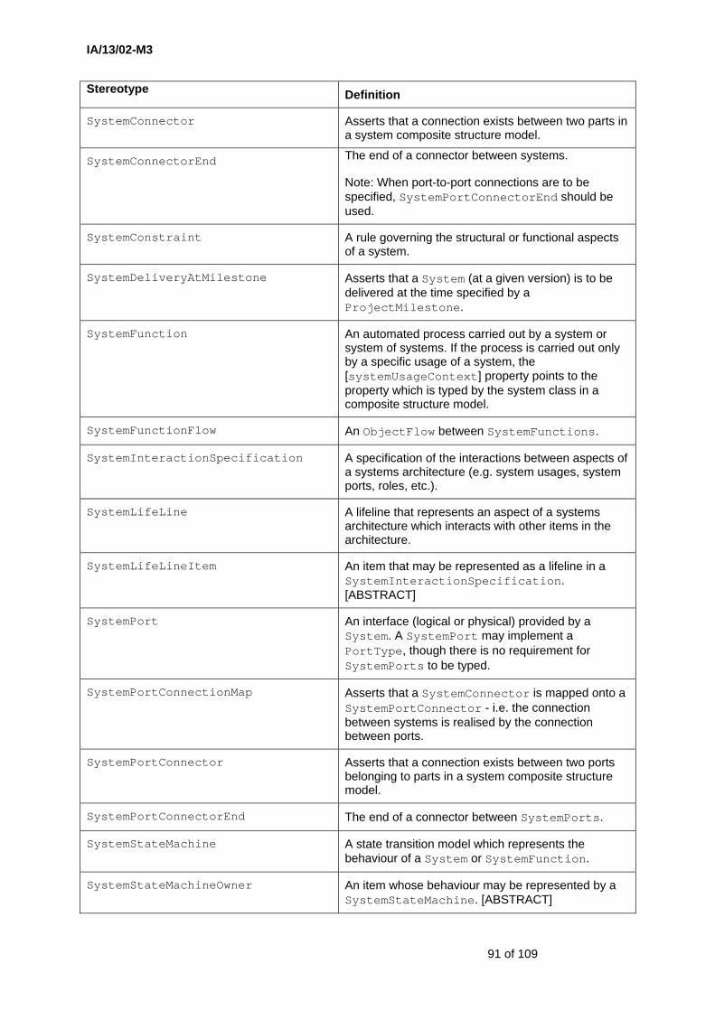
IA/13/02-M3
91 of 109
Stereotype Definition
SystemConnector Asserts that a connection exists between two parts in a system composite structure model.
SystemConnectorEnd The end of a connector between systems.
Note: When port-to-port connections are to be specified, SystemPortConnectorEnd should be used.
SystemConstraint A rule governing the structural or functional aspects of a system.
SystemDeliveryAtMilestone Asserts that a System (at a given version) is to be delivered at the time specified by a ProjectMilestone.
SystemFunction An automated process carried out by a system or system of systems. If the process is carried out only by a specific usage of a system, the [systemUsageContext] property points to the property which is typed by the system class in a composite structure model.
SystemFunctionFlow An ObjectFlow between SystemFunctions.
SystemInteractionSpecification A specification of the interactions between aspects of a systems architecture (e.g. system usages, system ports, roles, etc.).
SystemLifeLine A lifeline that represents an aspect of a systems architecture which interacts with other items in the architecture.
SystemLifeLineItem An item that may be represented as a lifeline in a SystemInteractionSpecification. [ABSTRACT]
SystemPort An interface (logical or physical) provided by a System. A SystemPort may implement a PortType, though there is no requirement for SystemPorts to be typed.
SystemPortConnectionMap Asserts that a SystemConnector is mapped onto a SystemPortConnector - i.e. the connection between systems is realised by the connection between ports.
SystemPortConnector Asserts that a connection exists between two ports belonging to parts in a system composite structure model.
SystemPortConnectorEnd The end of a connector between SystemPorts.
SystemStateMachine A state transition model which represents the behaviour of a System or SystemFunction.
SystemStateMachineOwner An item whose behaviour may be represented by a SystemStateMachine. [ABSTRACT]
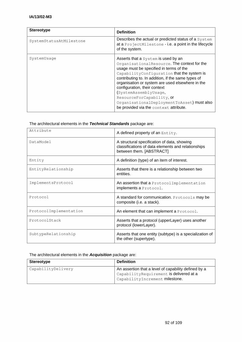
IA/13/02-M3
92 of 109
Stereotype Definition
SystemStatusAtMilestone Describes the actual or predicted status of a System at a ProjectMilestone - i.e. a point in the lifecycle of the system.
SystemUsage Asserts that a System is used by an OrganisationalResource. The context for the usage must be specified in terms of the CapabilityConfiguration that the system is contributing to. In addition, if the same types of organisation or system are used elsewhere in the configuration, their context (SystemAssemblyUsage, ResourceForCapability, or OrganisationalDeploymentToAsset) must also be provided via the context attribute.
The architectural elements in the Technical Standards package are: Attribute A defined property of an Entity.
DataModel A structural specification of data, showing classifications of data elements and relationships between them. [ABSTRACT]
Entity A definition (type) of an item of interest.
EntityRelationship Asserts that there is a relationship between two entities.
ImplementsProtocol An assertion that a ProtocolImplementation implements a Protocol.
Protocol A standard for communication. Protocols may be composite (i.e. a stack).
ProtocolImplementation An element that can implement a Protocol.
ProtocolStack Asserts that a protocol (upperLayer) uses another protocol (lowerLayer).
SubtypeRelationship Asserts that one entity (subtype) is a specialization of the other (supertype).
The architectural elements in the Acquisition package are:
Stereotype Definition
CapabilityDelivery An assertion that a level of capability defined by a CapabilityRequirement is delivered at a CapabilityIncrement milestone.
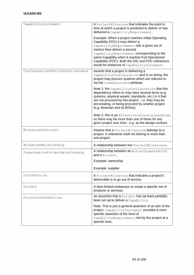
IA/13/02-M3
93 of 109
CapabilityIncrement A ProjectMilestone that indicates the point in time at which a project is predicted to deliver or has delivered a CapabilityRequirement.
Example: When a project reaches Initial Operating Capability (IOC) it may deliver a CapabilityRequirement with a given set of metrics then deliver a second CapabilityRequirement corresponding to the same Capability when it reaches Full Operational Capability (FOC). Both the IOC and FOC milestones would be instances of CapabilityIncrement.
ConfigurationOfProjectDeliverable Asserts that a project is delivering a CapabilityConfiguration and in so doing, the project may procure systems which are referred to via the itemsProcured attribute.
Note 1: the CapabilityConfiguration that this dependency refers to may have several items (e.g. systems, physical assets, standards, etc.) in it that are not procured by this project - i.e. they may be pre-existing, or being procured by another project (e.g. Bowman and its BISAs).
Note 2: this is an EffectivityConstrainedItem, so there may be more than one of these for any given project over time - e.g. as the design evolves.
MilestoneInProject Asserts that a ProjectMilestone belongs to a project. A milestone shall not belong to more than one project.
MilestoneRelationship A relationship between two ProjectMilestones.
OrganisationProjectRelationship A relationship between an ActualOrganisation and a Project.
Example: ownership
Example: supplier
OutOfService A ProjectMilestone that indicates a project's deliverable is to go out of service.
Project A time-limited endeavour to create a specific set of products or services.
ProjectAimsToDeliver An assertion that a Project has (at least partially) been set up to deliver a Capability.
Note: This is just a general assertion of an aim of the project. CapabilityIncrement provides a more specific assertion of the level of CapabilityRequirement met by the project at a specific time.

IA/13/02-M3
94 of 109
ProjectMilestone An event in a Project by which progress is measured.
Note: in the case of an acquisition project, there are two key milestones which shall be represented using subtypes - CapabilityIncrement and OutOfService.
ProjectOwnership A type of OrganisationProjectRelationship where the organisation is the party responsible for the project.
ProjectRelationship Relates a parent project (owningProject) to a sub-project (relatedProject).
ProjectThreadType A type of Workstream or line of development which is applicable to one or more ProjectType.
Note: In MOD terms there may be 6,7, or 8 lines of development, which would be represented using ProjectThreadType.
ProjectType A category of Project.
Example: "Programme"
Example: "Acquisition Project"
Example: "Training Programme"
RelatedProjectReference A reference to a sub-project from a ProjectRelationship.
ThreadInProject Relates a ProjectType to the threads it typically has - e.g. a procurement project having lines of development.
ThreadStatus An allowable value for specifying the status of a type of project thread.
ThreadStatuses An enumeration of the possible statuses for a given type of project thread.
ThreadStatusIndicator A property of a ProjectThreadType that can be used to indicate its status (e.g. progress) using a ThreadStatuses enumeration.
ThreadValue An instance value corresponding to a ThreadStatus.
Workstream A theme within a project against which progress may be measured at pre-determined milestones.
Note 1: A Workstream is an aspect or theme rather than a particular sub-project (for which ProjectRelationship would be used).
Note 2: A Workstream is an instance of a ProjectThreadType.
Example: The infrastructure LoD on the FRES project.
Example: The training LoD on the Apache project.
IA/13/02-M3
95 of 109
WorkstreamStatusAtMilestone A relationship between a Workstream and a ProjectMilestone which asserts the status (i.e. level of progress) of that Workstream for the Project at the time of the ProjectMilestone.
For example, a procurement project may have workstreams corresponding to lines of development. The status of each of workstream is summarised on the milestone in the AcV-2.
4.2 M3 Elements (Proposed Extensions to Core M3)
The architectural elements for the (Proposed) Effects package and the (Proposed) Services package have not yet been defined.
IA/13/02-M3
96 of 109
5 Comparison with DoDAF
One of the MOD aims for MODAF is to preserve an appropriate level of international alignment. This is because there is a degree of multinational co-operation in respect of architectures, implying that it is highly desirable that there is compatibility between architectural frameworks, the tools that support their use and the skills and knowledge employed by architects in different nations. MODAF is based on the DoDAF version 1 baseline [10].
This section summarises the main distinctions between MODAF – as represented by M3 – and the current version of DoDAF. It is recognised that DoDAF is in a state of evolution so the contents of this section should not be taken as indicating significant divergence from the evolving DoDAF12.
In summary, the following factors have led to differences compared with DoDAF version 1:
a. The need to model incremental acquisition programmes as these represent an increasingly common form of defence procurement
b. The need to model transformational programmes and their inter-dependencies
c. The need to model capabilities as the outcome from force development and capability integration programmes
d. The need to model physical attributes and capabilities and, by extension, flows of personnel, energy and materiel not just information
e. The need to integrate programme models into traditional architecture models in order to meet the needs of enterprise architects
f. The need to include services into architecture models in order to meet the needs of Service Oriented Architectures
g. The need to address Effects Based Operations
h. A drive towards a more coherent object oriented underpinning for the Architectural Framework.
None of these factors are believed to be specific to the UK procurement regime or UK defence architecture requirements. It is therefore expected that, over time, existing defence architectural frameworks like DoDAF will evolve to accommodate the changing needs of defence architects.
5.1 Strategic Viewpoint
The Strategic Viewpoint was introduced into MODAF to address the concerns of Capability Managers. In particular, strategic views describe capability taxonomy and capability evolution. The Viewpoint is an essential component of an enterprise architectural framework.
In DoDAF, it could be argued that this Viewpoint was not needed because, at the time of writing version 1 of DoDAF, it was envisaged that architecture models would be written in one of only two states ‘As Is’ (capturing the current capability) and ‘To Be’ (capturing the intended target capability).
MOD increasingly employs incremental acquisition to help to manage the risks of complex procurements and there is consequently a need to provide visualisations of the evolving capabilities so that Capability Managers can synchronise the introduction of capability increments across a Programme of Projects.
12 See Section 6.2.6 for reference to the OMG’s UPDM (UML Profile for MODAF/DODAF) initiative.
IA/13/02-M3
97 of 109
The views included within MODAF’s Strategic Viewpoint are based on the programme and capability visualisation techniques that are used by Capability Managers to capture the increasingly complex relationships between inter-dependent projects and capabilities.
Another justification for the Strategic Viewpoint within MODAF is the increasing importance of transformational programmes within the MOD (e.g. NEC, Logistics Transformation). These types of programme do not conform to the standard form of project and tend to be benefit-driven rather than capability delivery focused. An ability to model these transformational programmes, and their inter-dependencies, provides a potentially powerful tool for defence Enterprise Architects.
5.2 Acquisition Viewpoint
The Acquisition Viewpoint was introduced into MODAF to address the concerns of acquisition managers. In particular, acquisition views describe projects, how those projects deliver capabilities, the organisations contributing to the projects and dependencies between projects.
DoDAF takes a traditional view of architecture in which programme development is considered outside scope; to compensate for this, various DoDAF views represent the evolution of systems, technologies and standards (e.g. SV-8, SV-9 and TV-2).
The integration of acquisition views (organisational and project oriented views) with the more traditional architecture views is a characteristic aspect of MODAF-based enterprise architecture.
This approach provides most benefit when time-based views are accepted as being needed at all levels within an enterprise architecture.
5.3 SOA Services and Effects Based Operations
The proposal to incorporate support to Service Oriented Architectures within DoDAF (and the original MODAF baseline) represents a significant extension. This is a necessary step because of the increasing importance of SOA to both defence and commercial architectures.
The proposed approach for MODAF is based on international activities.
Since services may exist at all levels within an enterprise, it is also necessary to address effects. This will be based on the emerging doctrine associated with Effects Based Operations.
5.4 Model Concepts
The following DoDAF model concepts have been amended during the development of MODAF:
Needline: Node Connections (a new construct) enable modelling of flows of energy, material and personnel flows as well as the information flows that are addressed by Needlines (the M3 has deliberately avoided extending the definition of Needline to retain compatibility with DoDAF)13.
Node: MODAF reasserts the logical nature of an operational Node. What DoDAF calls System Nodes are Physical Assets in M3.
Organisation: MOD requires the preservation of the distinction between organisations and posts; this has been accomplished by introducing the Organisational Resource (in effect Organisational Resource plays the same role in MODAF as Organisation does in DoDAF). MODAF also makes a clear distinction between actual organisations and types of organisation.
13 This extension affects OV-2 only. OV-3 is unaffected.

IA/13/02-M3
98 of 109
System Function: In order to enable more refined modelling of information-rich equipment capabilities, a MODAF System Function may act on a particular set of Data Elements. Similarly, a MODAF Operational Activity may act on a particular set of Information Elements.
5.5 Specific Views
The DoDAF views relate to the Operational, Systems and Technical Viewpoints in MODAF.
In addition to the changes associated with the revised model elements, the following DoDAF views have been amended during the development of MODAF14:
SV-1 (system interface description): introduction of Capability Configuration
SV-2 (system connection specification): refinement of views to address Protocols and Protocol stacks
SV-11 (data model): greater integration with SV-4 and OV-7.
The MODAF form of OV-5 strives to combine support for object-oriented (UML) and structured methods (IDEF0).
Finally several of the DoDAF views have been amended to reflect integration with the Strategic and Acquisition Viewpoints in MODAF. These changes focus on the relationship between Capability Configurations and Capability Increment (milestones) as described in Figure 2-2 and Figure 2-7.
5.6 Role of UML
DoDAF does not have a meta-model as such. Rather it is underpinned by a data model known as CADM which is a large entity relationship data model. CADM provides the information model for DoDAF and also the model information exchange model.
Object oriented techniques have been used for some time in respect of DoDAF but there is a lack of a coherent underpinning representation that can be used by defence architects who prefer to model using UML or SysML.
The Object Management Group (OMG) characterises UML as “a general-purpose modelling language for specifying, visualising, constructing and documenting the artefacts of software systems, as well as for business modelling and other non-software systems”.
MOD has recognised the need for a formal underpinning to MODAF that reflects the fact that many defence architects which to use object oriented methods. Use of UML to define the MODAF Meta-Model has also been influenced by the decision to use the XMI open standard as the basis for the standard for MODAF model interchanges. Based on that decision, it was natural to develop an accompanying meta-model in UML [12].
The M3 is based on the UML meta-model. The UML meta-model is an information model which defines the various constructs used in UML. The purpose of the UML meta-model is to provide a structured underpinning for the language that can be used to define the structure of a repository for UML. The UML meta-model also defines the structure of XMI – the file format for UML tool interoperability.
The M3 is defined as a UML profile which specifies a way of using UML for a specialist purpose. A profile consists of a formal set of rules about how the UML modelling elements can be used, and a set of stereotypes suitable for the purpose of the profile. UML stereotypes are a way of extending existing UML modelling elements for a specific purpose, e.g. a model element called ‘System’ may be defined that extends the based “class” concept 14 Some of these changes have been proposed during the development of the initial baseline of the M3 and are not yet reflected in the MODAF Handbook.

IA/13/02-M3
99 of 109
in UML. UML stereotypes are ‘run time’ in the sense that an out-of-the-box UML tool can support them – this also means that XMI data exchange of models which use defined stereotypes can be achieved without a need to modify the XMI structure.
It should be noted that the MODAF Handbook does not mandate the use of UML in developing MODAF Products. However, architects wishing to use UML to represent MODAF Products shall ensure that the UML they produce is in line with the UML profile described by the M3.
Use of the formal modelling language in MODAF has introduced a discipline that to some extent has constrained the development of the M3. On the other hand, the ready availability of a number of UML-based architecture support tools ensures that there are benefits to MOD from this approach.
IA/13/02-M3
100 of 109
6 Changes to MODAF
This section describes changes to MODAF since v0.95, leading up to the initial baseline. It then describes drivers for future changes.
6.1 Recent Changes to M3
As a result of extensive stakeholder and peer review of the previous (v0.95) version of M3, a number of changes have been made, some of which are relatively significant.
Further integration of the Strategic Viewpoint
Nodes and Configured Capabilities
Incorporation of Physical Assets into the Operational Viewpoint
Incorporation of System Ports into the System Viewpoint
Enrichment of system data linkages
Further integration of the Acquisition Viewpoint
Proposed incorporation of services for SOA.
These changes are summarised below. A full change log is provided in this document as Appendix A.
6.1.1 Further integration of the Strategic Viewpoint
The Strategic views are new in MODAF and there has, to date, been relatively few examples of populated Strategic views. MODAF pilot activities are expected to address this.
In addition to the MODAF pilots, there have been three drivers for maturation of this Viewpoint from the M3 perspective:
1. Integrated treatment of Capability in line with the Defence Lines of Development
2. Representation of transformational activities
3. Incorporation of Enterprise Goals into the Strategic Viewpoint.
These changes are described in Sections 2.2.1 and 6.1.2.
The first change is intended to improve MODAF support for the Defence Lines of Development. Particular aspects of this are:
Capability integration across LODs: Introduction of Capability Configuration to supplement Fielded Capability (see Section 6.1.2).
Training/Personnel LODs: Introduction of Competence as a property of an Organisation or Post (see Section 2.2.1)
Concepts & Doctrine LOD: Use of Standards to tie doctrine into Capability Configurations (see Section 2.2.1)
Infrastructure LOD: Introduction of Physical Asset (see Section 6.1.3)
Organisation LOD: Association of Organisations and Posts through Organisational Resources that have Competences and contribute to Capability Configurations
Information LOD: Attention to the integration of data models into both operational and system models plus introduction of the concept that a function can act on some information, rather than just consume the information (see Section 6.1.4).
The second change reflects the increasing importance of transformational programmes within the MOD (e.g. NEC, Logistics Transformation). These types of programme do not conform to the standard form of project and some flexibility has had to be introduced into

IA/13/02-M3
101 of 109
MODAF in order to make it possible for architects to use the acquisition views to model them. Such programmes are often characterised in terms of goals and benefits rather than output capabilities.
The third change is intended to refine the representation of the Capability Vision in such a way that there are specific goal objects that are the subject of transformational change activities. Benefits (that tend to be the focus for transformational activities) are introduced as properties of Enterprise Goals. This change provides a strategic focus for measurable properties that are defined at lower levels in the architecture thereby facilitating the incorporation of Benefits Maps into architecture models.
6.1.2 Nodes and Capability Configurations
Nodes in MODAF are purely logical – they represent logical business space or battlespace roles, i.e. sets of required activities that collectively have meaning in defence (military) business terms. Nodes may be required at a location but do not have a physical presence.
The requirements implied by the definition of a Node can be met by the integration of component capability known in MODAF as a Capability Configuration. Capability Configurations are combinations of people, information, equipment and physical assets. These are created through force development activities and operated in accordance with doctrinal standards. See Section 2.2.1 for further details.
A Fielded Capability is an actual Capability Configuration.
6.1.3 Incorporation of Physical Assets into the Operational Viewpoint
Since Nodes are purely logical, there is a need to introduce an M3 element corresponding to the DoDAF concept of “Systems Node” - Physical Asset.
Introduction of Physical Assets is intended to:
Enable a distinction to be made between the logical (business or) battlespace roles represented by a Node and the actual Capability Configurations manifested through platforms and other facilities (supplemented with Organisations and Systems)
Allow the physical qualities of platforms and other facilities (including mobility and qualities related to protection from hostile action and the natural environment) to be modelled independently of the equipment that they host
Allow the Infrastructure Line of Development to be more easily addressed (in particular, enabling the modelling of the acquisition of significant Physical Assets such as training facilities).
It has proved most natural to define a Physical Asset to be a special type of System. Then Physical Assets may have System Functions, System Ports etc.
Note that capability is not exclusively realised by configured Physical Assets. Often, a capability can be realised to great effect using just human resources (the four-man SF team is the classic example).
6.1.4 Introduction of System Ports into the System Viewpoint
In order to encourage precise specifications for system interfaces, MODAF introduces ports, that provide a way of distinguishing between system interfaces at a relatively high level. Specifically, the ports of a system localise the ends of system-to-system connections.
6.1.5 Enrichment of system data linkages
On close examination a weakness was identified in DoDAF version 1. Within the System Viewpoint, there appeared to be a lack of integration of the data models represented in DoDAF’s SV-11 view.
IA/13/02-M3
102 of 109
Within the Operational Viewpoint, the logical data model captures the operational informatic entities and their relationships. These informatic entities are exchanged between operational activities (they are manifestations of activity dependence) and are conveyed between nodes by information exchanges. From the information perspective, this entails tight integration between the OV-2, OV-3, OV-5 and OV-7 views that address needlines, information exchanges, activity flows and data models respectively. In particular, an Information Element (OV-3) must be part of a Logical Data Model (OV-7).
A change has been introduced into the MODAF System Viewpoint to achieve an equivalent degree of integration between the relevant system views (SV-4, SV-6 and SV-11 addressing function flows, data exchanges and data models respectively).
6.1.6 Further integration of the Acquisition Viewpoint
Examination of the linkages between MODAF Viewpoints implied by earlier versions of the M3 revealed that the Acquisition Viewpoint was not well bound into the other Viewpoints.
A number of changes have been made to rectify this. See Section 2 and, in particular, Figure 2-8 for further details.
6.1.7 Proposed incorporation of services for SOA
Service Oriented Architectures (SOA) are receiving significant attention at the present time, both in industry and the MOD. It is essential that defence architectures are able to express constructs associated with SOA. Some international work has provided a starting point for a proposed extension to the core M3. This will need to be verified once the service-based views have been defined (this is future work).
Several factors have influenced the SOA proposal for MODAF:
It should be possible to create models of services and service interaction (including service orchestration) independent from systems and system functions; in effect, this is a requirement to be able to directly model service-to-service dependencies (so called service chains)
Services should either contribute to Capability Configurations or fulfil Node requirements
It should also be possible to relate the service models to system implementation models (with system functions realising the SOA services)
SOA services should, wherever possible, be designed to be stateless from the user perspective
However, there is a desire to retain the service-based modelling pattern for system interactions that has been used by the Integration Authority over the last few years in respect of ISSE modelling (specifically, the function-service-function pattern).
During the development of the services proposal, it became apparent that there was a need to introduce effects into MODAF.
6.2 Drivers for Future Change
The following drivers for future change have been identified:
Use of MODAF and M3 v1
Update of MODAF documentation
Development of service views
SysML
BPMN
IA/13/02-M3
103 of 109
International developments – the OMG UPDM and the IDEAS Group in particular.
6.2.1 Use of MODAF and M3 v1
Employment of MODAF continues to be sporadic and MODAF is not currently endorsed for all architecture-related projects and initiatives across the MOD.
As use of MODAF increases, the actual needs of MOD practitioners will be become more apparent and this may lead to evolution of the view definitions (and consequently the M3).
The M3 itself is a complex specification and there is currently only limited experience of its implementation. Continuing dialogue with tool vendors is likely to indicate requirements for change as a result of the identification of M3 implementation challenges.
The approach to taxonomies and structured vocabularies within MODAF is immature. The way in which the M3 links to the MODAF taxonomy may need to be amended once further progress is made in this respect.
6.2.2 Evolution of MODAF documentation
As discussed in Section 1.7, it has not been possible to update the MODAF documentation in line with the initial baseline of the M3. As indicated in Section 6.1 there have been several changes that are significant for MODAF. These will be the subject of future review of the current baseline documentation, i.e. the Technical Handbook and the deskbooks which provide guidance on the employment of MODAF by particular Communities of Interest.
On the other hand, the use of the current documentation may itself lead to changes in the M3.
6.2.3 Development of service views
In particular, the area of the M3 that is most likely to require change is the SOA service proposal. Since the M3 is intended to support the view definitions in the Technical Handbook, this part of the M3 will need to be reviewed once view definitions have been agreed for the SOA services.
6.2.4 SysML
The System Modelling Language (SysML) is intended to become a standardised modelling language for system engineering [10]. It was always intended that MODAF, and the M3 in particular, would benefit from the considerable effort that is being put into the construction of this modelling language.
The evolution of UML into the Systems Modelling Language (SysML) is serving to shed the language of some of its software-emphasis, and also bring in some new features that make it particularly attractive to systems engineers. SysML will have applicability across the whole systems engineering domain, including areas such as business process modelling, requirements specification and system architecting.
The following features of SysML are of particular interest to the M3, considered as a language for enterprise architectures (some have already been incorporated):
Requirement, a construct for modelling requirements and specifications
Measure, a construct for modelling measurable properties
Block, a construct for modelling composite structures which have behaviour15. 15 Block has not been included in M3 v1.0 simply because it was not a stable part of SysML at the time of publication. A future M3 should consider adopting Blocks for most cases where UML composite structure is used.
IA/13/02-M3
104 of 109
In addition, SysML fixes some “limitations” in UML 2.0. Activity decomposition in UML is possible in two (incompatible) ways: composite structure and call behaviour action. SysML forces both approaches to be used (with appropriate tracing between), and M3 has followed this approach. In addition, SysML introduces NestedConnectorEnd, a way of contextualising individual usages of a class in a composite class structure. M3 re-uses this concept.
SysML is the subject of an ongoing OMG process, i.e. it is not currently ratified. During this process two consortia have been preparing SysML proposals, each in the form of a UML profile. Recent developments have led to significant convergence between these proposals. The significance of this is that it has been judged possible to base certain M3 constructs within this initial baseline of the M3 on the emerging SysML specification [10]. These are shown colour-coded purple in the M3 diagrams.
6.2.5 BPMN
The Business Process Modelling Notation (BPMN) is intended to become the standardised modelling language for business process modelling.
In June of 2005, the Business Process Management Initiative (BPMI.org) and the Object Management Group (OMG) announced the merger of their Business Process Management (BPM) activities to provide thought leadership and industry standards for this domain [11]. The combined group has named itself the Business Modeling & Integration (BMI) Domain Task Force (DTF).
The BMI DTF may be expected to align the approach currently used in UML activity models with that in BPMN. This would then become a suitable candidate for OV-5 in the M3.
6.2.6 International developments
There are a number of international developments that may, in future, influence future evolution of the M3:
Further evolution of DoDAF (discussed in Section 5)
Efforts, based on the IDEAS Group, to achieve a level of international alignment in respect of architecture development
The OMG Request For Proposal (RFP) – UML Profile for MODAF/DODAF (UPDM) [13], which is likely in time to become the primary vehicle for harmonisation of DoDAF, MODAF and the emerging NATO Architectural Framework.
As a result of parallel work undertaken by MOD in respect of these international efforts, the MODAF Meta-Model is well placed to play a leading role in facilitating the harmonisation required across these international initiatives.
6.3 Change Cycle
The M3 Release Policy [7] has stated that the next review of the core M3 will take place 12 months from the initial baseline. The next review of the M3 will take into account further development (and hopefully ratification) of the SysML specification.
Since the incorporation of SOA services into the architectural framework is novel, and is not yet supported by any formally defined views, this part of the Meta-Model is subject to change.
IA/13/02-M3
105 of 109
Appendix A: M3 Change Log
This appendix contains the complete change log documenting all changes to the Meta-Model between v0.95 and v1.0.
A.1 Changes between v0.95 and v0.98
• SOA model added
- Based on initial research by Swedish Defence Materiel Administration
- Based on NATO's SOA requirements
- Consensus on common approach between MOD and NATO needed.
• AV-1 brought in line (as much as possible) with IEEE1471
- Architecture renamed "ArchitecturalDescription"
- Product renamed to "ArchitecturalProduct" and added to AV-1 scope
- Architecture added to keep consistency with IEEE1471 (ontologically, one could argue very strongly that there is no such thing as an "architecture", but 1471 has spoken)
- Other 1471 concepts added - Stakeholder, Concern, Environment
- Some 1471 concepts had to be renamed to fit the MODAF terminology 1471:viewpoint = modaf:view, 1471:view = modaf:product, 1471:System = modaf:enterprise.
• Taxonomy referencing system re-worked in AV-2.
• Capabilities
- Capability now represents the definition of a capability in general. It provides a mechanism to classify required capabilities (see next sub-bullet) into a set which is enduring
- RequiredCapability added - this represents the time-dependent requirements for capability
- FieldedCapability's definition refined to clarify that it is an actual instance of capability
- CapabilityConfiguration introduced to represent a typical configuration required to fulfil a capability.
• Moved a number of Stereotypes from the Core package to Operational:
- Resource, ResourceForNode, Node, NodeAssemblyUsage, NodeConnectionType, NodeConnector, NodeConnectorEnd
- InformationElement, DefinitionOfInformationElement.
• Moved a number of Stereotypes from the Core package to the MODAF All-Views package:
- TaxonomyReference.
• Created new package, "Technical Standards" and moved stereotypes to it:
- Standard.
• Created new package, "SysML" and moved stereotypes to it:
- NestedConnectorEnd, Requirement.
IA/13/02-M3
106 of 109
• Created new stereotype "Allocation" from SysML.
• MetaData stereotype added (extends comment) - ArchitectureMetaData now specialises MetaData.
• OperationalActivityAction relationship to its pins was cardinality 1 (an error) now changed to cardinality * (many).
• Needline no longer a subclass of NodeConnector - both are now sibling extensions of UML::Connector.
• AcV-1 is really an organizational breakdown, with references to the projects they own. So, the model for AcV-1 is now the same as OV-4 but with project relationships.
• ProjectOwnership stereotype added (used in AcV-1).
• Post renamed to "PostType".
• Organization renamed to "OrganizationType".
• OrgResourceReference (stereotype of UML::InstanceValue) added to clarify how ActualOrganization is related to the ActualOrganizationalResources which fill its roles.
• OpActivityInputPin and OpActivityOutputPin cardinality error now fixed - an operational activity can have more than one pin.
• All abstract classes are now labelled [ABSTRACT] in their description.
• In previous releases, there was some confusion about what the blue colouring of classes meant. For this version, blue indicates abstract. Grey indicates when a class is used in a view but not displayed - usually because it relates two elements that are in the view.
• IDEF0FlowEnd added (abstract) as superclass of control and mechanism pins in OV-5.
• NodeProvidesControlOrMechanism added to provide compatibility with DoDAF/CADM OV-5 - i.e. nodes themselves can act as the control or mechanism for activities. Not sure this is going to be used much in the UK, though...
• FunctionProvision (stereotype of Dependency) added to replace the direct relationship between System and SystemFunction which would only allow a function to be executed by one system. This approach allows multiple types of system to expose the same functionality.
• CapabilityVision now a composite class. Its text description is provided by the VisionStatement (stereotype of comment) and it has parts which are classed by Goal.
• RequiredCapability is now linked to the CapabilityVision via the CapabilityContributesToVision dependency.
• StV-2 M3 extract originally featured CapabilityComposition (mistake). In fact, this is a taxonomy view and should show specialisations of capabilities. New stereotype of uml::Generalization created: CapabilitySpecialisation. StV-4 still uses CapabilityComposition.
• StV-6 mistakenly relates operational activities to the capabilities that enable them. What it should really be doing is relating the capabilities to the essential task list. Hence new stereotype created called EnduringTask and this is now related to RequiredCapability in StV6, not OperationalActivity.

IA/13/02-M3
107 of 109
• InformationDescriptor and DefinitionOfInfoElement deleted. We now use the in-built UML represented relationship from InformationElement, redefined to "definedBy" to point at the entity which defines the information element.
• ResourceHasCompetence added - stereotype of property (composite class) to assert an organizational resource having a competence.
• Added new stereotype ActsUpon which relates an OperationalActivity to things that it acts upon (new stereotype ActivitySubject).
• Added FunctionsUpon - the systems equivalent of ActsUpon.
• OperationalConstraint restricted so that it can only apply to Node, OperationalActivity, Mission.
• TaskEnablement deleted - SV-5 model no longer shows direct link to capabilities. However, should a tool wish to overlay this info, it is possible to derive through CapabilityConfiguration.
• Capabilities Package renamed to "Strategic".
• All packages now numbered - e.g. "1 - All Views" - this is to enable correct section ordering when publishing the model.
• Standard now a stereotype of Class (from structured classes).
• ProtocolStack renamed to Protocol.
• ProtocolStackRelationship created to allow protocol stacks to be built using composite structure.
• Major changes to the way milestone status is handled in AcV-2
- ProjectThread is now ProjectThreadType
- ProjectThreadTypes are instantiated for each project as Workstream
- The possible statuses of a thread (e.g. red, amber, green) are defined as an enumeration (ThreadStatusIndicator, ThreadStatuses, ThreadStatus)
- WorkstreamStatusAtMilestone is now a slot, which instantiates ThreadStatusAtMilestone and which indicates the ThreadValue which points to the ThreadStatus.
• DataExchange and DataElement added (systems equivalent of InformationElement and InformationExchange).
• PhysicalProperty renamed to MeasurableProperty and brought in line with SysML (ValueType, Unit, Dimension).
• TemporalStateOfHLOC added to represent the epochs covered by the HighLevelOperationalConcept in OV-1. It is this element that has the metrics associated with it. It is related to the HighLevelOperationalConcept via HLOCTemporalPart.
• High-level overview diagrams added for each MODAF viewpoint. These diagrams show the major stereotype definitions from M3, but hide the relationship stereotypes. High-level relationships are represented using dependencies. These dependencies have no formal semantics in M3, and are purely to help understand the model.
IA/13/02-M3
108 of 109
• MODAF TWG Approved Changes on Operational Nodes - see minutes of meeting 17th Feb 2006.
• Removed: ResourceForNode.
• An op node can now only be realised by a CapabilityConfiguration, a FieldedCapability, or a Service, via the NodeRealisation stereotype (of UML::Realization).
• SystemUsage - now in context of CapabilityConfiguration - i.e. a given organization or post uses the system when contributing to the realised capability.
• PhysicalAsset added - subclass of System - to represent platforms and facilities.
• Hosting stereotype added - asserts that systems are hosted on physical assets.
• The physical resources contributing to a capability must either be an organizational resource or a physical asset - i.e. a system cannot contribute alone (it must be hosted on a physical asset, or used by an organization, or both).
• NetworkedCapabilityConnector & NetworkedCapabilityConnectorEnd removed.
• AcV-1/2 altered to provide tighter integration with strategic views. Projects now deliver capability instead of just procuring systems. This is done via the ConfigurationOfProjectDeliverable dependency relationship which also points at the procured systems to provide context.
• Impacts OV-2 - now only shows logical node structure.
• Impacts SV-1 - M3 usage requires that NodeRealisation and subclasses of CapabilityProvider be used to link the systems to the operational nodes (if the tool allows op nodes to be shown in OV-2).
• Impacts SV-1 - system nodes are now represented as physical assets.
• Impacts SV-2c - Op nodes are not shown on SV-2c, physical assets are.
A.2 Changes between v0.98 and v1.0
• SysML requirements stereotypes added as informative model (i.e. not normative) in All Views. This allows text requirements to be traced to any architectural element. Not all tools may wish to implement this though.
• ‘Organization’ renamed as ‘Organisation’ throughout model (affects a number of M3 element titles and definitions) following customary MOD usage and to align with the Defence Lines of Development.
• ActualCompetence had the client/supplier ends the wrong way round, now rectified.
• SystemPortConnectionMap had the client/supplier ends the wrong way round, now rectified.
• InformationExchangeMessage added - provides the missing link between sequence diagrams and IERs.
• ID attribute added to InformationExchange to support need for ID in SV-6.
• TypicalCompetence replaced with ResourceHasCompetence (now a property).

IA/13/02-M3
109 of 109
• ImplementsProtocol and ProtocolImplementation added to constrain which elements may implement a Protocol.
• CapabilityIncrement and OutOfService added as subclasses of ProjectMilestone. The reason for this is that these specific events inform other key areas of MODAF such as StV-3, StV-5, and SV-8.
• SV-9 re-worked after (quite correct) comments that it was actually different to SV-8 - i.e. it is a set of time-specific forecasts about changes to types of systems and standards. Hence Forecast (stereotype of comment, subtype of EffectivityControlledItem) and the abstract SubjectOfForecast have been added.
• Strawman Effects model added. Effect stereotype of OpaqueBehaviour, and RealizationOfEffect and NodeAffectsNode added on OV-2 for future considerations of effects-based operations.
• RequiredCapability first introduced in v0.98 is renamed to CapabilityRequirement.
• CapabilityFulfilment now removed. The link from capability to equipment is now via projects, using CapabilityIncrement and CapabilityDelivery. This means even if only StV-3 & 5 are being produced, a Project must also be created, with the appropriate CapabilityIncrement milestones - even if the equipment is already in service
• SV-1 meta-model excerpt extended to allow organisational aspects to be shown - i.e. organisations and post using systems, and deployed to assets.
• TemporalStateofHLOC renamed to the slightly less exotic AspectOfHLOC and now optionally includes the types of location for which the HighLevelOperationalConcept metrics are valid.
• IdentifiedCompetence removed - this is covered by the competences of the organizational resources specified in a capability configuration.
• Addition of two "cheat sheets" for implementors and advanced users - "Capability Delivery" and "Capability Deployment". These show the chain of dependency from capability to equipment. One chain goes via the acquisition route and the other shows how capability is deployed in a particular model (OV-2).