Mobile Valves 325 bar Proportional - Load Sensing Vickers... · 2014-01-10 · EATON Proportional...
16
Mobile Valves Proportional - Load Sensing Model CML60 325 bar 60 L/min Up to 8 sections Eaton F(x) ® Compliant
Transcript of Mobile Valves 325 bar Proportional - Load Sensing Vickers... · 2014-01-10 · EATON Proportional...

Mobile ValvesProportional - Load Sensing
Model CML60
325 bar 60 L/min
Up to 8 sectionsEaton F(x)® Compliant

2 EATON Proportional Load Sensing Mobile Valves E-VLMB-MC006-E July 2010
Table of Contents
General Information ................................................................................................................................................................................... 3
Model Code
Valve Section ........................................................................................................................................................................................ 4
Valve Assembly .................................................................................................................................................................................... 5
Specifications and Performance ................................................................................................................................................................ 6
Standard Section Electrohydraulic Schematics ........................................................................................................................................ 7
Standard Section Hydraulic Schematics .................................................................................................................................................... 8
Performance Data ..................................................................................................................................................................................... 9
Inlet and End Cover Schematics .............................................................................................................................................................. 10
Valve Bank Installation Dimensions ......................................................................................................................................................... 11
Valve Bank Schematic Examples ............................................................................................................................................................. 12
Section Installation ............................................................................................................................................................................. 13-14

3EATON Proportional Load Sensing Mobile Valves E-VLMB-MC006-E July 2010
The Eaton CML60 mobile valve is a load sensing, sectional proportional valve with a highly versatile design that offers ex-tensive relief options through the use of standard C-10-2 relief cavities. The CML60 valve can be utilized across the breadth of pump types rang-ing from fixed displacement pumps to pressure compen-sated, load sensing variable displacement pumps.
Increased productivity is the key user benefit of the CML60 load sensing proportional valve. This operator efficiency is achieved because each valve function is proportional to the spool position under all load conditions and independent of the number of valve functions in operation providing the total demand flow is less than pump flow. Additional benefits of the CML60 load sensing proportional valve include energy savings due to less fuel consumption and heat dissipo-tion.
Rated Flow:
Inlet: to 100 l/min (26.3 USgpm) Section: to 60 I/min (15.8 USgpm)
Rated Fatigue Pressure per NFPA T2.6.1:
280 bar (4050 psi) Inlet• Qualified at 1 million cycles
at 325 bar [4700 psi] test pressure
300 bar (4350 psi) Work Ports• Qualified for 1 million cycles
at 350 bar [5075 psi] test pressure
Standard Circuit Design Parallel circuit, closed center load sensing, inlet pressure compensated
Actuation Options
Hydraulic •
• Electrohydraulic Proportional
General Information
Features and Benefits
Precise Control
• EH proportional
– With or without manual handle back-up
– Can be used on/off
• Hydraulic pilot
Energy Efficiency
• Load sensing circuit design
Versatile Design
• Sectional design
– 1-8 sections
– Spool type, flow and actuation options
• Work ports accept Eaton’s Vickers® SiCV cartridges
– C-10-2 cavities
– Section pressure limitation available
• Inlet Options
– Unload/relief for fixed dis-placement pump systems
– Load sensing for variable-displacement flow com-pensated pumps
• Integral pressure reducing valve for EH pilot supply
Eaton F(x)® Compliant
• Control F(x)™ Software
• EFX, and SFX Controllers
Product Overview

4 EATON Proportional Load Sensing Mobile Valves E-VLMB-MC006-E July 2010
Model Code – Valve Section
CML60 ** - * - ** *** - ** 105 D 60 - N - R - G D N - 00 - 10
1 62 1593 10 11 12 13 14 16754
1 Load Sensing Proportion-al Valve CML60 –
2 ActuationE0 – Electrohydraulic H0 – HydraulicEM – Electrohydraulic w/
manual overrideHM – Hydraulic w/ manual
override 3 Ports
B – 1/2 BSP D – Direct port STC, -8 M – ISO 6149 metric, M18 S – SAE, -8 T – SAE, -10
4 Port A Relief Valve
00 – No cavities P1 – Plugged C1 – Check Valve
L1 – LS Relief Valve (opposite port coding must be the same)
F1 – Relief Valve, Direct Act-ing, Poppet Type, Fixed Relief (RV1-10-F-0-30/*-00) (standard for 3000 psi and below)
S1 – Relief Valve, Direct Act-ing, Poppet Type, Screw Ad-just Relief (RV1-10-S-0-30/*-00)
A1 – Relief Valve, Direct Act-ing, Poppet Type, Fixed Relief (RV1-10-F-0-30 Internal Adjust Relief (RV1-10-I-0-30/*-00)
F2 – Relief Valve, Pilot Oper-ated, Fixed Relief (RV5-10-F-0-50/*-00) (standard for 3000-4000 psi)
S2 – Relief Valve, Pilot Oper-ated, Screw Adjust Relief (RV5-10-S-0-50/*-00)
A2 – Relief Valve, Pilot Oper-ated, Internal Adjust Relief (RV5-10-I-0-50/*-00)
5 Pressure setting for Port A
Check valve crack pressure in psi (OR) relief valve nominal setting pressure in psi; available in 50 psi increments from 500 to 4350 psi depending on type.
Coded as in the following examples:
005 – 5 psi Anti-Cav Check
050 – Relief pressure, 500 psi (72.4 BAR) MIN etc. increments of 50 psi (3.45 BAR)
435 – Relief pressure, 4350 psi (300 BAR) MAX
6 Port B Relief Valve
00 – No cavities P1 – Plugged C1 – Check Valve
L1 – LS Relief Valve (opposite port coding must be the same)
F1 – Relief Valve, Direct Act-ing, Poppet Type, Fixed Relief (RV1-10-F-0-30/*-00) (standard for 3000 psi and below)
S1 – Relief Valve, Direct Act-ing, Poppet Type, Screw Ad-just Relief (RV1-10-S-0-30/*-00)
A1 – Relief Valve, Direct Act-ing, Poppet Type, Internal Ad-just Relief (RV1-10-I-0-30/*-00)
F2 – Relief Valve, Pilot Oper-ated, Fixed Relief (RV5-10-F-0-50/*-00) (standard for 3000-4000 psi)
S2 – Relief Valve, Pilot Oper-ated, Screw Adjust Relief (RV5-10-S-0-50/*-00)
A2 – Relief Valve, Pilot Oper-ated, Internal Adjust Relief (RV5-10-I-0-50/*-00)
7 Port B Pressure Setting
Check valve crack pressure in psi (OR) relief valve nominal setting pressure in psi; available in 50 psi increments from 500 to 4350 psi depending on type.
Coded as in the following examples:
005 – 5 psi Anti-Cav Check
050 – Relief pressure, 500 psi (72.4 BAR)
435 – Relief pressure, 4350 psi (300 BAR)
8 Spool Type
D – 4 way cylinder H – 4 way motor
9 Spool Flow Rating
05 – 5 lpm 10 – 10 lpm 15 – 15 lpm 30 – 30 lpm 45 – 45 lpm 60 – 60 lpm
10 Compensator
N – Noncompensated
C – Inlet pressure compen-sated
11 Build Type (Determined by viewing the valve stack
from the end cover)
R – RH Build. Port A is on the right. Manual override handle, if present, is on the right.
L – LH Build (non-standard). Port A is on the left. Manual override handle, if present, is on the left.
12 Coil Voltage
G – 12 Vdc H – 24 Vdc 0 – No Coil
13 Coil Connector
D – Deutsch Y – Amp Jr L – Lead Wires 0 – No Coil
14 Wire Lead Length
0 – No Lead Wire
N - Integrated Connector (Deutsch and Amp Jr.
B - Wire Lead length 24 inch (Standard)
15 Special Features
00 – None
16 Design Level
10 – Design Level
8
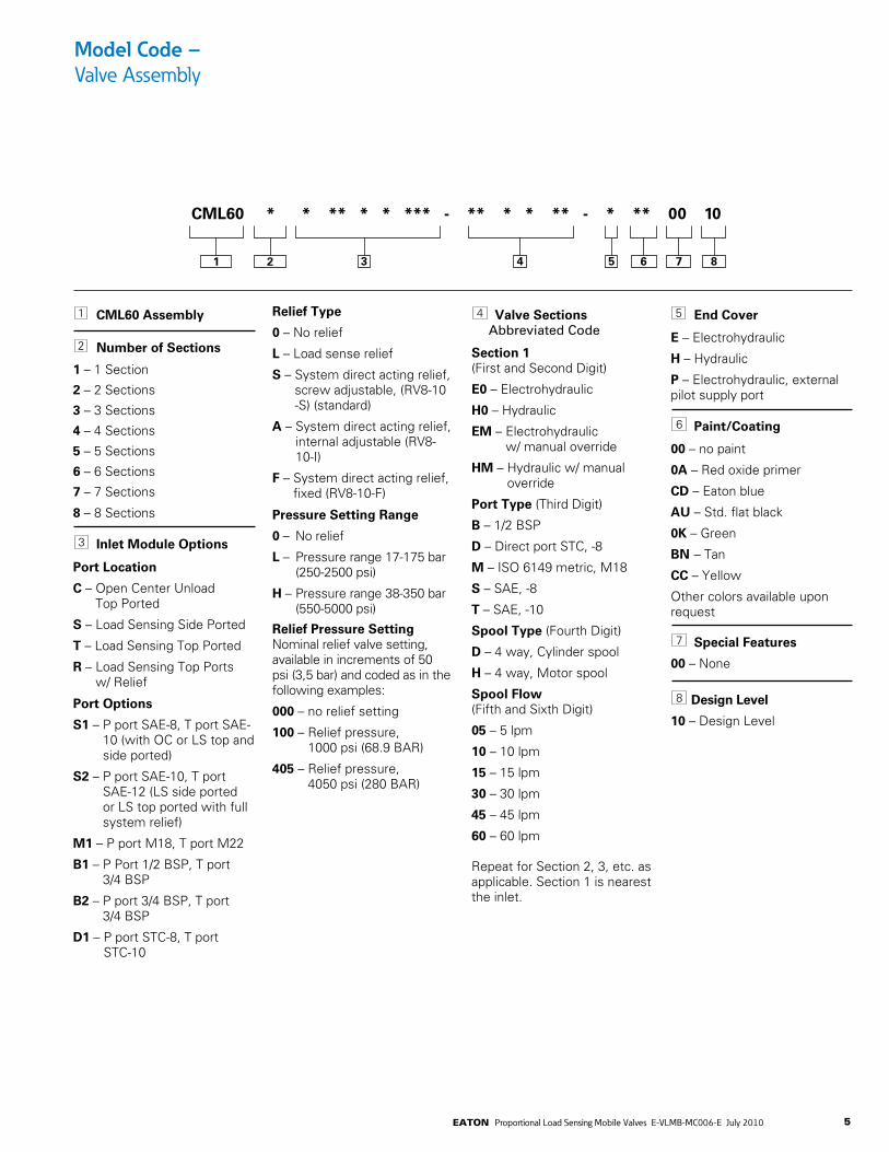
5EATON Proportional Load Sensing Mobile Valves E-VLMB-MC006-E July 2010
1 CML60 Assembly
2 Number of Sections
1 – 1 Section
2 – 2 Sections
3 – 3 Sections
4 – 4 Sections
5 – 5 Sections
6 – 6 Sections
7 – 7 Sections
8 – 8 Sections
3 Inlet Module Options
Port Location
C – Open Center Unload Top Ported
S – Load Sensing Side Ported
T – Load Sensing Top Ported
R – Load Sensing Top Ports w/ Relief
Port Options
S1 – P port SAE-8, T port SAE-10 (with OC or LS top and side ported)
S2 – P port SAE-10, T port SAE-12 (LS side ported or LS top ported with full system relief)
M1 – P port M18, T port M22
B1 – P Port 1/2 BSP, T port 3/4 BSP
B2 – P port 3/4 BSP, T port 3/4 BSP
D1 – P port STC-8, T port STC-10
Relief Type
0 – No relief
L – Load sense relief
S – System direct acting relief, screw adjustable, (RV8-10-S) (standard)
A – System direct acting relief, internal adjustable (RV8-10-I)
F – System direct acting relief, fixed (RV8-10-F)
Pressure Setting Range
0 – No relief
L – Pressure range 17-175 bar (250-2500 psi)
H – Pressure range 38-350 bar (550-5000 psi)
Relief Pressure Setting Nominal relief valve setting, available in increments of 50 psi (3,5 bar) and coded as in the following examples:
000 – no relief setting
100 – Relief pressure, 1000 psi (68.9 BAR)
405 – Relief pressure, 4050 psi (280 BAR)
4 Valve Sections Abbreviated Code
Section 1 (First and Second Digit)
E0 – Electrohydraulic
H0 – Hydraulic
EM – Electrohydraulic w/ manual override
HM – Hydraulic w/ manual override
Port Type (Third Digit)
B – 1/2 BSP
D – Direct port STC, -8
M – ISO 6149 metric, M18
S – SAE, -8
T – SAE, -10
Spool Type (Fourth Digit)
D – 4 way, Cylinder spool
H – 4 way, Motor spool
Spool Flow (Fifth and Sixth Digit)
05 – 5 lpm
10 – 10 lpm
15 – 15 lpm
30 – 30 lpm
45 – 45 lpm
60 – 60 lpm Repeat for Section 2, 3, etc. as applicable. Section 1 is nearest the inlet.
5 End Cover
E – Electrohydraulic
H – Hydraulic
P – Electrohydraulic, external pilot supply port
6 Paint/Coating
00 – no paint
0A – Red oxide primer
CD – Eaton blue
AU – Std. flat black
0K – Green
BN – Tan
CC – Yellow
Other colors available upon request 7 Special Features
00 – None
8 Design Level
10 – Design Level
Model Code – Valve Assembly
CML60 * * ** * * *** - ** * * ** - * ** 00 10
1 2 7 863 4 5

6 EATON Proportional Load Sensing Mobile Valves E-VLMB-MC006-E July 2010
Specifications and Performance
CML60 Proportional Load Sensing Valve
Rated Fatigue Pressure Inlet 280 bar [4050 psi] Work Ports 300 bar [4350 psi]
Maximum Pressure Inlet 325 bar [4700 psi] Work Ports 350 bar [5075 psi]
Rated Inlet Flow 100 lpm [26.3 gpm]
Fluid Cleanliness and Viscosity See Hydraulic Fluid Recommendations bulletin 03-401
Maximum Fluid Temperature 107oC (225oF)
Construction Sectional
Work Sections 1-8
Maximum Leakage, 20 cc/min @ 69 bar [1000 psi] Cylinder Workport to Tank
Port Types SAE o-ring ISO 6149 Metric BSP Direct port STC
Inlet Section Options Unload/relief for fixed displacement pump systems Load sensing inlet
Work Section Options General Accept Eaton SiCV cartridges C-10-2 cavities - work port on port 1, tank on port 2
Spools 4 way cylinder (work ports closed in neutral) 4 way motor (work ports closed in neutral) Maximum flows, 5 to 60 lpm Adjustable Travel Stops
Actuation Electrohydraulic Hydraulic Electrohydraulic w/ manual override Hydraulic w/ manual override
Outlet Section Options EH with external pilot supply port and integral pressure reducing valve Plain (for hydraulic pilot) Integral pressure reducing valve for EH pilot supply
EH Pilot Coil Voltages 12 Volt DC, 1500 mA current max 24 Volt DC, 750 mA current max
EH Pilot Coil Terminations Integral Deutsch DT04-2P Integral Amp Jr. Dual Leadwires
Mounting Options Stamped mounting plate Mounting attitude unrestricted
Electrohydraulic interface Eaton F(x) compliant, EFX, and SFX Controllers

7EATON Proportional Load Sensing Mobile Valves E-VLMB-MC006-E July 2010
Standard Section Electrohydraulic Schematics
w/ work port reliefs
w/o reliefs w/o reliefs
w/ work port reliefsw/ work port reliefsw/ manual override
w/o reliefsw/ manual override
w/o reliefsw/ manual override
w/ work port reliefsw/ manual override
w/ load sense reliefw/ load sense relief
w/ load sense reliefw/ manual override
w/ load sense reliefw/ manual override
A B
SOLB1SOLA1
A B
SOLB1SOLA1
A B
B1A1
A B
B1A1
A B
SOLB1SOLA1
A B
SOLB1SOLA1
A B
B1A1
A B
B1A1
A B
SOLB1SOLA1
A B
SOLB1SOLA1
A B
B1A1
A B
B1A1
The same configurations are also available with motor spools (work ports open to tank in neutral).
Cylinder Spools
8 EATON Proportional Load Sensing Mobile Valves E-VLMB-MC006-E July 2010
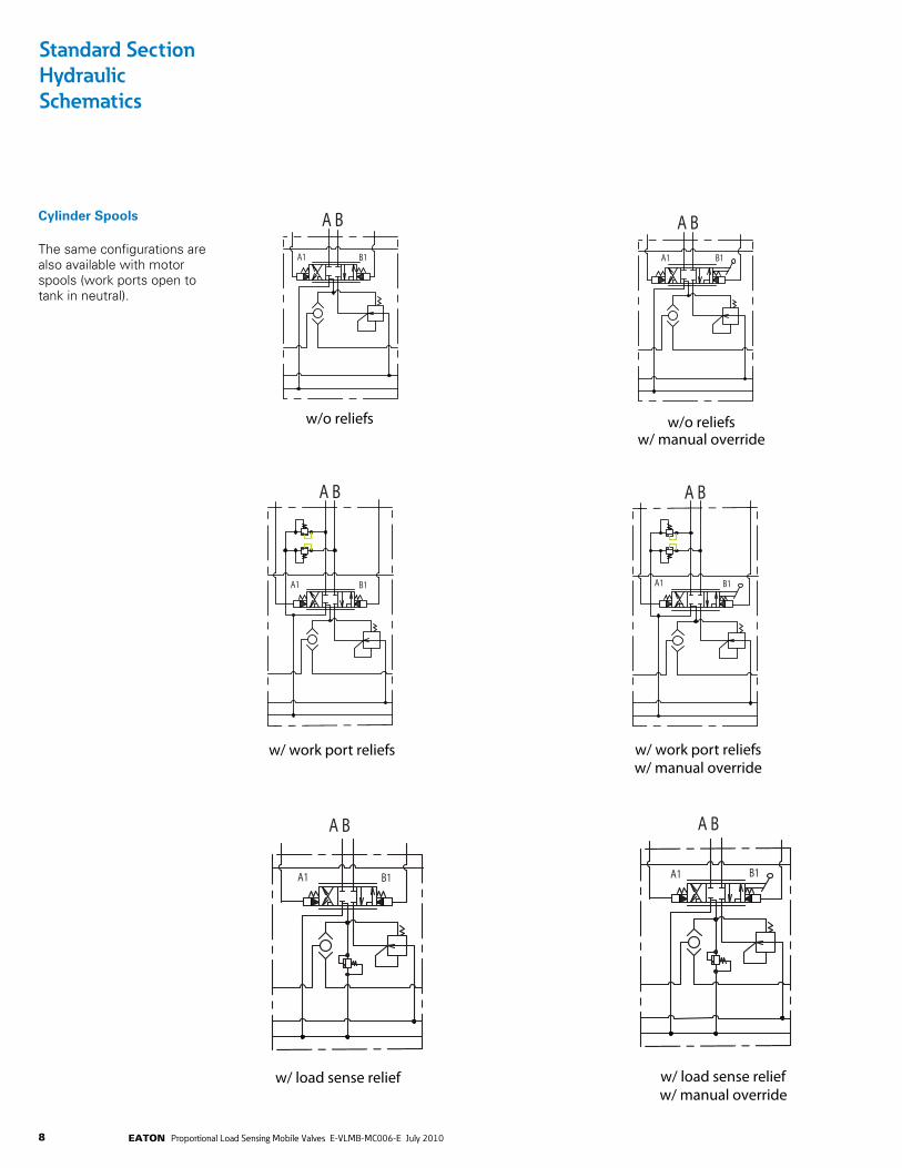
Standard Section Hydraulic Schematics
w/ work port reliefs
w/o reliefs w/o reliefs
w/ work port reliefsw/ work port reliefsw/ manual override
w/o reliefsw/ manual override
w/o reliefsw/ manual override
w/ work port reliefsw/ manual override
w/ load sense reliefw/ load sense relief
w/ load sense reliefw/ manual override
w/ load sense reliefw/ manual override
A B
SOLB1SOLA1
A B
SOLB1SOLA1
A B
B1A1
A B
B1A1
A B
SOLB1SOLA1
A B
SOLB1SOLA1
A B
B1A1
A B
B1A1
A B
SOLB1SOLA1
A B
SOLB1SOLA1
A B
B1A1
A B
B1A1
Cylinder Spools
The same configurations are also available with motor spools (work ports open to tank in neutral).

9EATON Proportional Load Sensing Mobile Valves E-VLMB-MC006-E July 2010
Performance Data
CML60 Flow vs Current
CML60 Flow vs Pressure
0
10
20
30
40
50
60 64
600 700 800 900 1000 1100 1200 1300 1400
Flow
(LPM
)
Current (mA)
Flow (LPM) vs Current (mA)
0
2
4
6
8
10
12
14
16 17
600 700 800 900 1000 1100 1200 1300 1400
Flow
(gpm
)
Current (mA)
Flow (GPM) vs Current (mA)
15 lpm Spool
45 lpm Spool
60 lpm Spool
30 lpm Spool
15 lpm Spool
30 lpm Spool
45 lpm Spool
60 lpm Spool
Maximum flow ± 5% of rated flow. Cracking current ± 0.25 mA. Hysteresis <20%
Maximum flow ±5% of rated flow. Cracking pressure ±0.5 bar (±7 psig) Hysteresis <20%
0
10
20
30
40
50
60 64
5.5 6.5 7.5 8.5 9.5 10.5 11.5 12.5 13.5 14.5 15.5 16.5 17.5 18.5
Flow
(LPM
)
Pressure (BAR)
Flow (LPM) vs Pressure (BAR)
0 1 2 3 4 5 6 7 8 9
10 11 12 13 14 15 16 17
75 95 115 135 155 175 195 215 235 255 275 295
Flow
(gpm
)
Pressure (psig)
Flow (GPM) vs Pressure (PSIG)
15 lpm Spool
30 lpm Spool
45 lpm Spool
60 lpm Spool
15 lpm Spool
30 lpm Spool
45 lpm Spool
60 lpm Spool

10 EATON Proportional Load Sensing Mobile Valves E-VLMB-MC006-E July 2010
Inlet and End Cover SchematicsHydraulic and Electrohydraulic
T
P
LS
T
P
LS
T
P
LS
X
Open Center Inletw/ LS Relief
ElectrohydraulicEndcoverLoad Sensing Inlet
HydraulicEndcover
X
XX
X
Load Sensing Inletw/ Full Relief
) ( ) (
) (
Open Center Inlet & Hydraulic Endcover
Load Sense Inlet w/Full Relief & Hydraulic Endcover
Load Sense Inlet & Hydraulic Endcover
Load Sense Inlet w/Full Relief & Eletrohydraulic Endcover
Load Sense Inlet & Eletrohydraulic Endcover
Open Center Inlet & Eltrohydraulic Endcover

11EATON Proportional Load Sensing Mobile Valves E-VLMB-MC006-E July 2010
Valve Bank Schematic Examples
Electrohydraulic Load Sense Valve Bank Example
Hydraulic Open Center Valve Bank Example

12 EATON Proportional Load Sensing Mobile Valves E-VLMB-MC006-E July 2010
Table 2
For Open Center Inlet Only P-Port Tightening Torque T-Port Tightening TorqueSAE-10 42-46 N-m (30-35 ft-lb) SAE-12 88-100 N-m (65-75 ft-lb)SAE-8 34-41 N-m (25-30 ft-lb) SAE-10 68-75 N-m (50-55 ft-lb)M18 42-46 N-m (30-35 ft-lb) M22 68-75 N-m (50-55 ft-lb)
Table 1
No. of Center Sections 1 2 3 4 5 6 7 8Dimension “A” (mm) 38 76 114 152 190 228 266 304Dimension “A” (in) 1.5 3.0 4.5 6.0 7.5 9.0 10.5 12.0
Valve Bank Installation Dimensions
Hydraulic and ElectrohydraulicEndcover Configuration
Maximum Overall Envelopefor Center Section
Load Sensing with Full System Reliefand Open Center Inlet Port Configuration
Note: Dimensions are in mm
Open Center Inlet Configuration
Note: Dimensions are in mm
Load Sensing Inlet with Full System ReliefConfiguration
Note: Dimensions are in mm
Center Section1-8
13.5
38045.0
45.0
5.0
5.0
97.037.0
2.0 30.0
25.037.0
52.5
36.5
3.242.9
16
138
57.0
50.0
37.0
18.530.0
18.5
37.0
24.083.051.041.0
3.8
8331.0 30.0 13.5
P PortTightening TorqueReferTable 2
P PortTightening TorqueReferTable 2
T PortTightening TorqueRefer Table 2
T PortTightening TorqueRefer Table 2
C-1Ø-2 CavityTightening Torque
68-75N-M (SØ-55FT-lb)
4 Stacking RodsTightening Torque17-23 N-m(13-17 ft-lb)On Both Sides
4 Stacking RodsTightening Torque17-23 N-m(13-17 ft-lb)On Both Sides
Tightening Torque102-115 N-m(75-85 ft-lb)
'LS' Relief, OpenCenter Only
'LS' Port SAE-4Tightening Torque14-16 N-m(10-12 ft-lb)Mounting Bolts
Tightening Torque- 42-58 N-m
42.93.2
36.5
16.0A
(Refer Table-1)
Mounting BoltsTightening Torque - 42-58 N-m
'LS' Port SAE-4Tightening Torque14-16 N-m(10-12 ft-lb)
Mounting BoltsTightening Torque - 42-58 N-m
R0.22 Typ2 Places
Y
Y
102.5
Ø11.1
24
54.543.9

13EATON Proportional Load Sensing Mobile Valves E-VLMB-MC006-E July 2010
Section Installation Dimensions
Hydraulic Section Installa-tion Dimensions Minimum Envelope
Note: Dimensions are in mm
18.5
73.4
73.4
121.2
34
81.5
81.5
97
48.5
78
37
121.2
30
19.2
30
30
303419.2
29.5
51
38
(Upto Spotface)
(Upto Spotface)
(Upto Spotface)
PORT A
PORT B

14 EATON Proportional Load Sensing Mobile Valves E-VLMB-MC006-E July 2010
Electrohydraulic Section Installation Dimensions Maximum Envelope
Section Installation Dimensions
Note: Dimensions are in mm
( )50( -30°)28°
( -30°)28°
233.8
48.5
97.0
130.6
130.6
39.534.029.5
83.0
19.2
19.8
163.8
121.2
MAX146.1
MAX146.1
37.0
18.5
38.0
30.0
30.0
41.5
78.0
14°
Ø31.75
51.0(Upto Spotface)
141.0
PORT A
PORT B

15EATON Proportional Load Sensing Mobile Valves E-VLMB-MC006-E July 2010
Application Notes

Eaton Hydraulics Group USA14615 Lone Oak RoadEden Prairie, MN 55344USATel: 952-937-9800Fax: 952-294-7722www.eaton.com/hydraulics
EatonHydraulics Group EuropeRoute de la Longeraie 71110 MorgesSwitzerlandTel: +41 (0) 21 811 4600Fax: +41 (0) 21 811 4601
EatonHydraulics Group Asia PacificEaton Building4th Floor, No. 3 Lane 280 Linhong Rd.Changning District Shanghai 200335ChinaTel: (+86 21) 5200 0099Fax: (+86 21) 5200 0400
© 2010 Eaton CorporationAll Rights Reserved Printed in USADocument No. E-VLMB-MC006-E2July 2010