Mobile Traffic Engineering with Application Visibility and ... · CHAPTER 24-1 Cisco Bring Your Own...
76
CHAPTER 24-1 Cisco Bring Your Own Device (BYOD) CVD 24 Mobile Traffic Engineering with Application Visibility and Control (AVC) Revised: March 6, 2014 What’s New: The following sections have been added to this chapter: • AVC Protocol Packs (Featuring Cisco Jabber Support) • Converged Access Application Visibility • Converged Access AVC Configuration via CLI • Converged Access AVC Configuration via GUI • Converged Access AVC Monitoring via CLI Executive Summary Mobile wireless traffic is soon about to exceed wired traffic on a global basis and is comprised mainly of mobile video applications. Furthermore, the devices generating wireless traffic are shifting away from traditional laptops towards smartphones and tablets. As such, the volume, composition, and device-shift of mobile application traffic can pose a challenge to network administrators tasked with ensuring their quality. Business use cases for managing mobile applications include: • Improving the quality of wireless voice from cellular-quality to toll-quality • Enhancing the quality of experience for wireless video applications • Expediting the response times for business critical data applications over wireless devices • Managing background application traffic by preventing bulky traffic flows from monopolizing bandwidth away from more transaction-oriented flows, thus further improving user productivity • Controlling non-business applications on wireless networks, including social networking applications, video and media-downloading applications, peer-to-peer sharing applications, gaming applications, etc. This document presents design considerations relating to wireless (and wired) network quality management by overviewing the underlying technologies involved and showing how these interact to create an end-to-end solution.
-
Upload
phamkhuong -
Category
Documents
-
view
214 -
download
0
Transcript of Mobile Traffic Engineering with Application Visibility and ... · CHAPTER 24-1 Cisco Bring Your Own...
C H A P T E R 24
Mobile Traffic Engineering with Application Visibility and Control (AVC)Revised: March 6, 2014
What’s New: The following sections have been added to this chapter:
• AVC Protocol Packs (Featuring Cisco Jabber Support)
• Converged Access Application Visibility
• Converged Access AVC Configuration via CLI
• Converged Access AVC Configuration via GUI
• Converged Access AVC Monitoring via CLI
Executive SummaryMobile wireless traffic is soon about to exceed wired traffic on a global basis and is comprised mainly of mobile video applications. Furthermore, the devices generating wireless traffic are shifting away from traditional laptops towards smartphones and tablets. As such, the volume, composition, and device-shift of mobile application traffic can pose a challenge to network administrators tasked with ensuring their quality.
Business use cases for managing mobile applications include:
• Improving the quality of wireless voice from cellular-quality to toll-quality
• Enhancing the quality of experience for wireless video applications
• Expediting the response times for business critical data applications over wireless devices
• Managing background application traffic by preventing bulky traffic flows from monopolizing bandwidth away from more transaction-oriented flows, thus further improving user productivity
• Controlling non-business applications on wireless networks, including social networking applications, video and media-downloading applications, peer-to-peer sharing applications, gaming applications, etc.
This document presents design considerations relating to wireless (and wired) network quality management by overviewing the underlying technologies involved and showing how these interact to create an end-to-end solution.
24-1Cisco Bring Your Own Device (BYOD) CVD

Chapter 24 Mobile Traffic Engineering with Application Visibility and Control (AVC)Executive Summary
However, the main theme of this document is detailed design guidance on best-practice Quality of Service (QoS) configurations for Cisco Wireless LAN Controllers (highlighting the new Cisco Application Visibility and Control feature) as well as for network switches to achieve the business use cases for mobile application management.
24-2Cisco Bring Your Own Device (BYOD) CVD

Chapter 24 Mobile Traffic Engineering with Application Visibility and Control (AVC)Macro Trends and Business Requirements
Macro Trends and Business RequirementsMobile application traffic is continuing to explode. According to Cisco’s Visual Networking Index Forecast, global mobile data traffic will grow 13-fold from 2012 to 2017.1
Additional key trends relating to mobile devices, applications, and traffic include:
• By 2014, wireless IP traffic will exceed wired (and will exceed 60% by 2016).2
• By 2016, the number of mobile-connected devices will exceed three-times the world’s population.3
• By 2016, non-PC devices (such as smartphones and tablets) will generate 30% of all IP traffic.4
• By 2017, tablets will account for more than 12% of global mobile data traffic.5
• By 2017, mobile video will represent two-thirds of all mobile data traffic.6
• By 2017, 45% of global mobile data traffic will be offloaded to fixed networks via WiFi or femtocell.7
Therefore (non-PC) mobile devices will generate exponentially more traffic in the coming years, with the bulk of this traffic traversing wireless networks and with the traffic itself being primarily composed of video applications.
Since QoS is critical to the overall Quality of Experience (QoE) of video-based applications, network administrators need to concern themselves with ensuring that the applications traversing their networks—especially their wireless LANs (where the majority of traffic will be sourced from)—is being adequately provisioned.
1. Cisco Visual Networking Index: Global Mobile Data Traffic Forecast Update, 2012-2017 http://www.cisco.com/en/US/solutions/collateral/ns341/ns525/ns537/ns705/ns827/white_paper_c11-520862.pdf
2. Cisco Visual Networking Index: Forecast and Methodology, 2011-2016 http://www.cisco.com/en/US/solutions/collateral/ns341/ns525/ns537/ns705/ns827/white_paper_c11-481360.pdf
3. Cisco Visual Networking Index: Forecast and Methodology, 2011-2016 http://www.cisco.com/en/US/solutions/collateral/ns341/ns525/ns537/ns705/ns827/white_paper_c11-481360.pdf
4. Cisco Visual Networking Index: Forecast and Methodology, 2011-2016 http://www.cisco.com/en/US/solutions/collateral/ns341/ns525/ns537/ns705/ns827/white_paper_c11-481360.pdf
5. Cisco Visual Networking Index: Global Mobile Data Traffic Forecast Update, 2012-2017 http://www.cisco.com/en/US/solutions/collateral/ns341/ns525/ns537/ns705/ns827/white_paper_c11-520862.pdf
6. Cisco Visual Networking Index: Global Mobile Data Traffic Forecast Update, 2012-2017 http://www.cisco.com/en/US/solutions/collateral/ns341/ns525/ns537/ns705/ns827/white_paper_c11-520862.pdf
7. Cisco Visual Networking Index: Global Mobile Data Traffic Forecast Update, 2012-2017 http://www.cisco.com/en/US/solutions/collateral/ns341/ns525/ns537/ns705/ns827/white_paper_c11-520862.pdf
24-3Cisco Bring Your Own Device (BYOD) CVD
Chapter 24 Mobile Traffic Engineering with Application Visibility and Control (AVC)Cisco Application Visibility and Control (AVC) for Wireless LAN Controllers
Business use-cases for wireless application quality include:
• Guaranteeing voice quality from wireless applications meets enterprise VoIP requirements. For example, independent third-party testing has shown that wireless VoIP quality over congested wireless networks can be improved from a Mean Opinion Score (MOS) of 3.92 (which is considered cellular quality) to 4.2 (which is considered toll quality) by applying the recommendations detailed later in this document.1
• Ensuring video applications—both interactive and streaming—are delivered to/from wireless devices with a high Quality of Experience, so that users can communicate and collaborate more efficiently and effectively—regardless of their location or device. As another example, the same testing has shown video quality to improve from Good (9 fps) to Excellent (14 fps) after respective policies were deployed.2
• Provisioning preferred services for business-critical applications running on wireless devices, such as Virtual Desktop applications, sales applications, customer relationship management (CRM) applications, and enterprise resource planning (ERP) applications, etc. Yet another example has shown Citrix traffic latency to decrease by a factor or 7 (from 14 ms to 2 ms) when properly provisioned over the wireless network.3
• De-prioritizing “background” application traffic (i.e., applications that send data to/from servers, rather than directly to other users and which do not directly impact user-productivity), such as email, file-transfers, content distribution, backup operations, software updates, etc.
• Identifying, de-prioritizing (or dropping) non-business applications, which can include social networking applications, peer-to-peer file-sharing applications and type of entertainment and/or gaming applications so that network resources are always available for business-oriented applications.
A key facilitating technology for identifying and managing application traffic over wireless networks to meet these business use case requirements is the Cisco Application Visibility and Control (AVC) feature for Cisco Wireless LAN Controllers, which is discussed next.
Cisco Application Visibility and Control (AVC) for Wireless LAN Controllers
Beginning with Cisco WLC software release 7.4, the Application Visibility and Control set of features—already supported on Cisco routing platforms, like ASR 1000s and ISR G2s—became available on WLC platforms, including the Cisco 2500, 5500, 7500, 8500 WLCs, and WiSM2 controllers in central switching mode.
The AVC feature set increases the efficiency, productivity, and manageability of the wireless network. Additionally, the support of AVC embedded within the WLAN infrastructure extends Cisco’s application-based QoS solutions end-to-end.
1. Syracuse University: Network Technology Performance Evaluation Cisco Application Visibility and Control (AVC) (February 1, 2013) http://www.cisco.com/en/US/prod/collateral/wireless/cisco_avc_application_improvement.pdf
2. Syracuse University: Network Technology Performance Evaluation Cisco Application Visibility and Control (AVC) (February 1, 2013) http://www.cisco.com/en/US/prod/collateral/wireless/cisco_avc_application_improvement.pdf
3. Syracuse University: Network Technology Performance Evaluation Cisco Application Visibility and Control (AVC) (February 1, 2013) http://www.cisco.com/en/US/prod/collateral/wireless/cisco_avc_application_improvement.pdf
24-4Cisco Bring Your Own Device (BYOD) CVD
Chapter 24 Mobile Traffic Engineering with Application Visibility and Control (AVC)Cisco Application Visibility and Control (AVC) for Wireless LAN Controllers
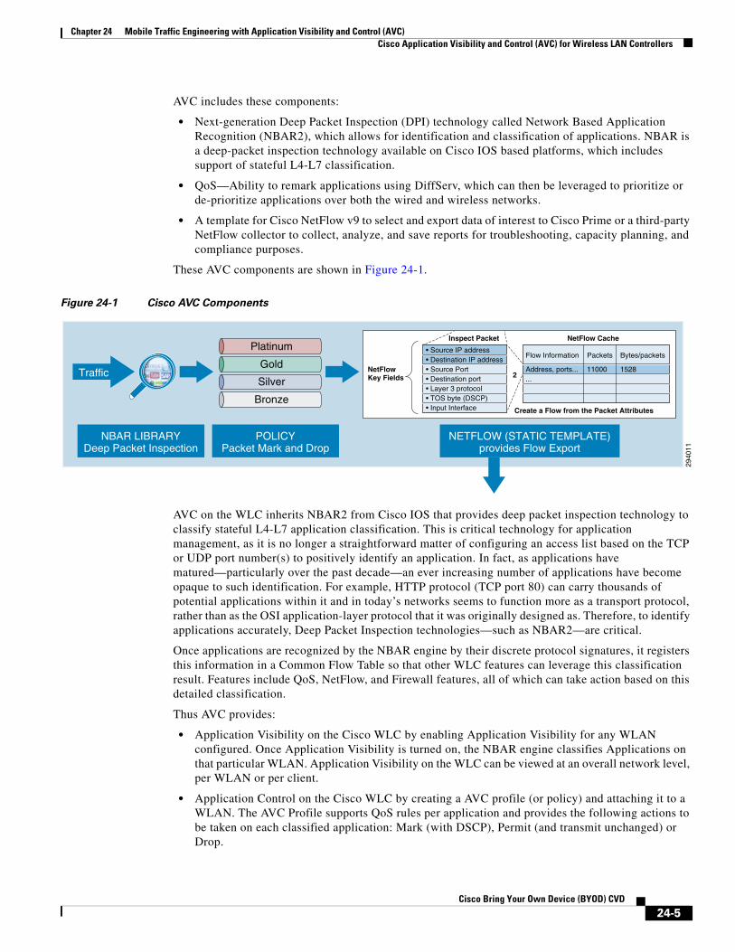
AVC includes these components:
• Next-generation Deep Packet Inspection (DPI) technology called Network Based Application Recognition (NBAR2), which allows for identification and classification of applications. NBAR is a deep-packet inspection technology available on Cisco IOS based platforms, which includes support of stateful L4-L7 classification.
• QoS—Ability to remark applications using DiffServ, which can then be leveraged to prioritize or de-prioritize applications over both the wired and wireless networks.
• A template for Cisco NetFlow v9 to select and export data of interest to Cisco Prime or a third-party NetFlow collector to collect, analyze, and save reports for troubleshooting, capacity planning, and compliance purposes.
These AVC components are shown in Figure 24-1.
Figure 24-1 Cisco AVC Components
AVC on the WLC inherits NBAR2 from Cisco IOS that provides deep packet inspection technology to classify stateful L4-L7 application classification. This is critical technology for application management, as it is no longer a straightforward matter of configuring an access list based on the TCP or UDP port number(s) to positively identify an application. In fact, as applications have matured—particularly over the past decade—an ever increasing number of applications have become opaque to such identification. For example, HTTP protocol (TCP port 80) can carry thousands of potential applications within it and in today’s networks seems to function more as a transport protocol, rather than as the OSI application-layer protocol that it was originally designed as. Therefore, to identify applications accurately, Deep Packet Inspection technologies—such as NBAR2—are critical.
Once applications are recognized by the NBAR engine by their discrete protocol signatures, it registers this information in a Common Flow Table so that other WLC features can leverage this classification result. Features include QoS, NetFlow, and Firewall features, all of which can take action based on this detailed classification.
Thus AVC provides:
• Application Visibility on the Cisco WLC by enabling Application Visibility for any WLAN configured. Once Application Visibility is turned on, the NBAR engine classifies Applications on that particular WLAN. Application Visibility on the WLC can be viewed at an overall network level, per WLAN or per client.
• Application Control on the Cisco WLC by creating a AVC profile (or policy) and attaching it to a WLAN. The AVC Profile supports QoS rules per application and provides the following actions to be taken on each classified application: Mark (with DSCP), Permit (and transmit unchanged) or Drop.
2940
11
Platinum
Gold
Silver
Bronze
• Source IP address• Destination IP address• Source Port• Destination port• Layer 3 protocol• TOS byte (DSCP)• Input Interface
NetFlowKey Fields
NetFlow Cache
Create a Flow from the Packet Attributes
2
Inspect Packet
Traffic
NETFLOW (STATIC TEMPLATE)provides Flow Export
POLICYPacket Mark and Drop
NBAR LIBRARYDeep Packet Inspection
Address, ports......
Flow Information
11000
Packets
1528
Bytes/packets
24-5Cisco Bring Your Own Device (BYOD) CVD

Chapter 24 Mobile Traffic Engineering with Application Visibility and Control (AVC)Challenges and Solutions for Managing Application Quality over Wireless Media
Key business use cases for AVC include:
• Classifying and marking wireless mobile device applications—Identifying and differentiating realtime voice, video, or business-critical applications from less important, but potentially bandwidth-hungry-applications so as to prioritize, de-prioritize, or drop specific application traffic.
• Capacity planning and trending—Baselining the network to gain a clearer understanding of what applications are consuming bandwidth and trending application usage to help network administrators plan for infrastructure upgrades.
To better understand how AVC works in WLAN scenarios, an overview of the challenges and tools for managing quality of service over wireless media may be helpful (and is discussed next, along with a summary of the overall strategic recommendations for deploying quality of service policies across an enterprise). Network administrators already familiar with these concepts may find it more efficient to skip the following sections and to proceed directly to Configuring Downstream QoS Policies for Mobile Applications and Configuring Upstream QoS Policies for Mobile Applications.
Challenges and Solutions for Managing Application Quality over Wireless Media
To better understand design recommendations available for managing application quality over wireless media, it is beneficial to lay some context as to the challenges and solutions available for managing traffic over this media. To begin with, it should be noted that the very nature of wireless as a transmission media makes it less predictable and controllable from a quality perspective, as compared to wired networks.
For example, wired campus networks operate at full-duplex mode, with endpoints being able to transmit data at any time at maximum capacity. For example, a server connected to a switch by a 1 Gbps full-duplex link can theoretically both send and receive at 1 Gbps of data simultaneously, without having to contend with other stations for access to the medium.
Wireless networks, on the other hand, operate in half-duplex mode, with endpoints contending among themselves as well (as with the wireless access point) for the opportunity to transmit data. This is because in WLANs, every station associated to a particular access point (AP) must share the radio frequency (RF) with all the other stations; however, only one station—including the AP itself—may transmit at a given time. The result of this is that each station must contend with all the other stations for airtime. WLANs are-by definition-a multiple-access, broadcast medium, meaning that if more than one station transmits at any one time, no other station is able to understand what has been transmitted. Put another way, if two (or more) stations began transmitting data simultaneously over a WLAN, this would result in a collision. This limitation means that to avoid RF interference, full-duplex is simply not possible in WLANs (if both transmitting and receiving are performed on the same channel, as is the case in most WLAN deployments). Before quality can even be addressed over WLANs, the first requirement is finding a solution to avoiding collisions over wireless media.
IEEE 802.11 Distributed Coordination Function (DCF)A baseline understanding of the Distributed Coordination Function (DCF)—operating at the 802.11 MAC layer (which is responsible for scheduling and transmitting Ethernet frames onto the wireless medium)—is essential to understanding the subsequent enhancements that allow for wireless quality of service.
DCF has the following key components, which are briefly described below:
24-6Cisco Bring Your Own Device (BYOD) CVD

Chapter 24 Mobile Traffic Engineering with Application Visibility and Control (AVC)Challenges and Solutions for Managing Application Quality over Wireless Media
• Collision Sense Multiple Access/Collision Avoidance (CSMA/CA)
• Short Interframe Space (SIFS)
• DCF Interframe Space (DIFS)
• Contention Window (CW)
Collision Sense Multiple Access/Collision Avoidance (CSMA/CA)
Wi-Fi wireless networks are completely egalitarian, meaning that all wireless stations have equal access to the medium. In fact, even the AP has no more priority to access the medium than the client stations do. For example, a wireless IP phone has to abide by exactly the same principles as a wireless laptop, regardless of the fact that one of them might be transmitting real-time VoIP traffic and the other might be transmitting peer-to-peer (P2P) traffic. Since each client, and thus each application, has an equal opportunity to transmit frames at any given time, there must be an orderly system to coordinate the transmission of packets onto the medium. If no control were implemented, there would be a high probability of a collision. Additionally, the more clients associated to the AP, the higher the likelihood of collisions occurring. Furthermore, each time a collision occurs, stations would reattempt their transmissions, likely causing additional collisions in the process.
A similar problem existed in the early days of wired Ethernet, when half-duplex links and hubs were common. In half-duplex wired Ethernet environments collisions were a common outcome of multiple end-stations trying to transmit frames onto the wire at the same time. To address this situation, a system called Carrier Sense Multiple Access/Collision Detection (CSMA/CD) was developed. CSMA/CD is a set of rules that all end stations are required to follow when trying to transmit a frame onto the medium. For example, if a collision occurred, the stations involved in the collision would follow a strict set of backoff rules, involving random timers that help to reduce the probability of a future collision next time round. CSMA/CD thus proved a relatively effective mechanism to reduce collisions on half-duplex Ethernet networks.
Note While CSMA/CD worked well enough, the problem of collisions was to be obviated altogether in wired networks by introducing switching technology, which provided dedicated collision domains to each network segment. In this manner, no endpoint contended for media access with any other endpoint, as each had a dedicated collision domain between itself and the switch and as such could then operate at full-duplex capacity.
However while it may seem that CSMA/CD might likewise be applicable to wireless networks, there is a key difference: wireless stations have no way to detect a collision.
In a wired network, transmissions are sent as bursts of energy on the wire that can be reflected back to the end stations, thus allowing accurate detection of collisions. In a wireless medium, the RF energy is shared over the air, meaning reflections of the energy wave do not come back to the sending station, thus making collision detection impossible; hence CSMA/CD is an impractical approach for WLANs.
Notwithstanding this, the IEEE modified the CSMA/CD mechanism to accommodate wireless networks, as Carrier Sense Multiple Access/Collision Avoidance (CSMA/CA). The techniques differ in that CSMA/CD deals with what to do after a collision occurs, whereas CSMA/CA works to prevent a collision in the first place.
To understand this better, consider a person participating in an audio conference call. If many people are on the call together, there is a good chance that one person may begin talking at the same time as another, making both of them unintelligible to everyone else (effectively, a “collision”). If the parties used a CSMA/CD approach, they would pause for a few seconds and then try talking again in the hopes that they would not again talk at the same time, so that at least one of them could be understood. On the other
24-7Cisco Bring Your Own Device (BYOD) CVD

Chapter 24 Mobile Traffic Engineering with Application Visibility and Control (AVC)Challenges and Solutions for Managing Application Quality over Wireless Media
hand, if the parties were following a more polite CSMA/CA approach, then instead of simply starting to talk on the conference call (while hoping that no one else would at the same time), each party would wait patiently for a quiet period. Then, when they were certain that no one else was talking, they would begin. Additionally, the other parties would recognize and respect that one party was talking and would remain silent until they had completed speaking (without interruption).
Thus CSMA/CA opts to listen to the channel first to see if any transmissions are in progress and only when the channel is free does it attempt to send its frame. If a collision does occur even after listening and waiting, the wireless station deals with it in a similar way to CSMA/CD, by waiting for a random backoff period before it tries to resend the frame.
However it is important to note that CSMA/CA can never fully guarantee that a collision won’t occur; rather, it reduces the probability that a collision will occur by trying to “avoid” a future collision. CSMA/CA is a bit like arriving in your car at a four-way stop at the same time as three other drivers. Although you might try very hard to avoid a collision by looking both ways very carefully before driving into the intersection, you can never fully guarantee what the other driver will do. If you make a decision to proceed, there is always a slight possibility that the other driver might do the same thing at the same time and thus there is always the possibility of a collision. The same goes for WLAN stations that operate using CSMA/CA.
Short Interframe Space (SIFS)
So how does a sending station know that its transmission succeeded? Since, due to the broadcast nature of the wireless medium, collisions cannot be detected (they can only be avoided with a measure of probability), there is an obvious need to confirm whether a transmission was successful. To solve this problem, DCF ensures that each frame is acknowledged once the transmission is successfully received. Specifically, there is a provision in DCF where all clients keep silent after a transmission finishes so the receiving station has a chance to send the acknowledgement. This is period is called the Short Interframe Space (SIFS). This ensures that the transmitting station knows that it does not need to retransmit and it can move on to its next frame.
DCF Interframe Space (DIFS)
To help control and organize the transmission of frames on the wireless medium, DCF uses some clever rules whereby the contending stations wait for different periods of time before they can transmit their frames onto the channel. A central and key concept to how DCF operates is the DCF Interframe Space (DIFS). DIFS is a pre-established, fixed wait timer observed by all stations before they attempt transmission of a frame onto the channel.
Note There are actually several Interframe Space (IFS) types used in 802.11 networks; however, for the purposes of this discussion attention is focused only on SIFS and DIFS.
As mentioned, CSMA/CA provides a framework of “listen before you talk” for wireless stations. When a wireless station wants to transmit a frame, the first thing it does is to wait the appropriate DIFS time. Once this DIFS countdown has finished, if the medium is still clear, it transmits. DIFS is like a level set for all stations that want to transmit. If they all just started transmitting as soon as they had a frame in the queue, collisions would be plentiful. By waiting the DIFS period it gives a chance for the station to confirm that the channel is indeed clear for transmission.
Figure 24-2 shows the operation of Interframe Spaces (SIFS and DIFS) within DCF.
24-8Cisco Bring Your Own Device (BYOD) CVD

Chapter 24 Mobile Traffic Engineering with Application Visibility and Control (AVC)Challenges and Solutions for Managing Application Quality over Wireless Media
Figure 24-2 Interframe Spaces Operation
Contention Window (CW)
However, it may be the case that after waiting for the DIFS period to expire, the DCF process detects the medium is not idle. If this is the case, the station waits (technically speaking the station will “defer”) for a random period of time, called the contention window (CW). The first time a station needs to defer, the CW random backoff period is set from 0 to a maximum value known as CWmin. There is an obvious advantage to waiting a random period of time, for if multiple stations are all trying to transmit at the exact same time because a collision occurred and they all backed off for the same length of time, collisions would continually occur. After the CW timer expires the station again looks to see if the medium is free and if it is, it begins transmission.
However, if after the CW timer expires the sending station detects that the medium is still not clear, then it will:
• Defer again until the wireless medium is finally clear.
• Wait again for the DIFS period.
Then:
• Wait for another (longer) backoff period.
At first, the station doubles the CW value it used previously. However, if the station continually finds that the medium is not clear, then the station will continue to double the backoff window each time it tries to send the frame. It keeps on doing this up to a maximum amount of time, known as the CWmax value. This continues until it either it transmits the frame or the Time to Live (TTL) expires.
The amount of time that the station counts down is not actually measured in seconds, but rather in slot times. The slot time is a time value derived from the RF characteristics of the radio network and so it is unique for each network (but the actual length of these times is in microseconds, with 802.11 specifying about 20 microseconds for a slot time). As an example, in the case of IEEE 802.11n, the CWmin default is 15 slot times (~300 µs or 0.3 ms) and CWmax is 1023 slot times (~20,460 µs or 20.46 ms).
Due to the variable nature of contention windows, it is easy to see how significant amounts of delay variation (jitter) can be introduced into the packet flows. Figure 24-3 illustrates Contention Window Operation.
Defer access
Slot time
Contention window
DIFS
SIFS
Busy medium Next frame
Select slot and decrement backoffas long as the medium is idle
(t)Backoff window
2941
69
24-9Cisco Bring Your Own Device (BYOD) CVD

Chapter 24 Mobile Traffic Engineering with Application Visibility and Control (AVC)Challenges and Solutions for Managing Application Quality over Wireless Media
Figure 24-3 Contention Window Operation
To illustrate how this works, if the random backoff for a station was initially set to 10 slot times, the second backoff would be 20. If the channel is still busy, the CW backoff is increased to 40, then 80, then 160, then 320, and finally 640 (as 640 doubled would exceed the CWmax value of 1023 slot times). At this point, if the frame has not been sent, the process begins again. These retries continue until the packet TTL is reached. This process of doubling the backoff window is referred to as binary exponential backoff.
DCF Operation
Consider an example of the DCF process might apply to a real world contention scenario. As illustrated in Figure 24-4, five stations associated to the same AP and all are trying to send data at approximately the same time.
CWmin
CWmax
3163
127
255
511
1023 1023 1023
retries
2941
70
24-10Cisco Bring Your Own Device (BYOD) CVD

Chapter 24 Mobile Traffic Engineering with Application Visibility and Control (AVC)Challenges and Solutions for Managing Application Quality over Wireless Media
Figure 24-4 DCF Operation
The DCF operation steps illustrated in Figure 24-4 are as follows:
Step 1 Station A successfully sends a frame; three other stations also want to send frames, but must defer to Station A traffic.
Step 2 After Station A completes the transmission, all the stations must still defer to the DIFS. When the DIFS is complete, stations waiting to send a frame can begin to decrement the backoff counter, once every slot time, and can send their frame.
Step 3 The backoff counter of Station B reaches zero before Stations C and D, and therefore Station B begins transmitting its frame.
Step 4 When Station C and D detect that Station B is transmitting, they must stop decrementing the backoff counters and defer until the frame is transmitted and a DIFS has passed.
Step 5 During the time that Station B is transmitting a frame, Station E receives a frame to transmit, but because Station B is sending a frame, it must defer in the same manner as Stations C and D.
Step 6 When Station B completes transmission and the DIFS has passed, stations with frames to send begin to decrement the backoff counters. In this case, the Station D backoff counter reaches zero first and it begins transmission of its frame.
Step 7 The process continues as traffic arrives on different stations.
IEEE 802.11e/WMMAs can be seen from the previous section’s analysis of the DCF model, there is no provision to differentiate service levels by traffic types, thus quality assurance is not possible using legacy DCF. To address this (and other limitations) the IEEE 802.11e task group provided enhancements to the original 802.11 specification that recommended several modifications to the way DCF operates that would facilitate a differentiated services model. These 802.11e modifications to the DCF model have been rolled into the wider 802.11-2007 standard (which is essentially a retrofit of the original 802.11 specification). The IEEE 802.11e model was also certified by the Wi-Fi Alliance as the Wireless Multimedia (WMM) model; as such these terms generally refer to the same mechanisms and are used interchangeably in this paper.
DIFS DIFS DIFS
Station A
Station B
Station C
Station D
Station E
Frame
Frame
Frame
Frame
Defer
Defer Defer Defer
Defer
Defer
Defer
Defer
Backoff time
Backoff time remaining
2941
71
24-11Cisco Bring Your Own Device (BYOD) CVD

Chapter 24 Mobile Traffic Engineering with Application Visibility and Control (AVC)Challenges and Solutions for Managing Application Quality over Wireless Media
The 802.11e task group has provided many enhancements to the overall 802.11 specification, but the key goal was to introduce an intelligent system of application traffic differentiation on wireless radio interfaces. Two of the most significant changes proposed by this task group were:
• To support marking within wireless frames by supporting a 3 bit marking value known as 802.11e User Priority (UP); 802.11e UP is essentially the same as 802.1p CoS marking, but for wireless frames (as opposed to wired Ethernet tagged frames).
• To replace DCF with a new MAC layer protocol known as Enhanced Distributed Channel Access (EDCA), which introduces the concept of relative prioritization by giving different application traffic varied access levels to the wireless media.
However, a critical point to understand about wireless QoS tools is that—unlike wired QoS tools—these can only offer a greater probability of one traffic type being differentiated from another, not an absolute guarantee of it.
IEEE 802.11e/WMM introduced major enhancements over DCF, which in turn enables a QoS toolset over Wi-Fi networks. Each of these enhancements is briefly described:
• 802.11e User Priorities
• Access Categories (AC)
• Enhanced Distributed Coordination Function (EDCF)
• Arbitration Interframe Spacing (AIFS)
• Contention Window Enhancements
• Transmission Opportunity (TXOP)
• Call Admission Control (TSpec)
802.11e User Priorities
IEEE 802.11e/WMM introduced a new frame format, shown in Figure 24-5, which includes support for a 3 bit marking field—compatible with 802.1D priority and 802.1p CoS—that is referred to as 802.11e User Priority (UP).
Figure 24-5 WMM Frame Format and 802.11e UP
2941
72
Framecontrol Dur A1 A2 A3 A4Seq
controlQoS
control Body FCS
2 2 6 6 6 2 0 or 6 0 or 2 n 4
0 ackpolicy EOSP 0 UP
15-7 6-5 4 3 2-0
Acknowledge ------- 00Do not acknowledge ------- 01 End of service
period802.11e UP
24-12Cisco Bring Your Own Device (BYOD) CVD

Chapter 24 Mobile Traffic Engineering with Application Visibility and Control (AVC)Challenges and Solutions for Managing Application Quality over Wireless Media
Access Categories (AC)
IEEE 802.11e/WMM specifies four different access categories, which are:
• Voice (AC_VO)
• Video (AC_VI)
• Best-Effort (AC_BE)
• Background (AC_BK)
IEEE 802.11e also supports a default mapping of User Priority markings to these access categories; these mappings are shown in Table 24-1.
Note An important item to note regarding the 802.11e/WMM AC model shown in Table 24-1 is that several CoS values in this WMM model do not line up with their IETF DSCP counterparts. For example, voice is mapped to a 802.11e UP value of 6. However, in wired networks, voice is typically marked 802.1p CoS value of 5, as this corresponds to the three Most Significant Bits (MSB) of the IETF recommended (six-bit) DSCP marking value for voice traffic of EF/46 (based on RFCs 32461 and 45942). The root cause of this marking incompatibility is that the IETF defines Layer 3 marking standards (i.e., DSCP), while the IEEE defines Layer 2 standards (like 802.1p CoS and 802.11e UP). Unfortunately, this sometimes leads to confusion and inconsistencies with the marking schemes that must be dealt with by the network engineer. These mapping considerations are discussed in greater detail later.
Note There is no relative priority between UP or CoS markings assigned to a single access category over the WLAN; for example, flows marked with either UP or CoS values of 4 and 5 are assigned to the video/gold WMM access category, but there is no difference in treatment between these flows.
Note While the WMM uses specific application designations for these access categories (Voice, Video, Best Effort, and Background), Cisco WLC software uses a more generic designation based on precious metals: platinum, gold, silver and bronze. Nonetheless each set of names refers to the same underlying
Table 24-1 IEEE 802.11e/WMM Access Categories, Mappings and Designations
Relative Priority 802.11e UP 802.11e Access Category (AC) WMM Designation Cisco WLC Designation
Highest 7 AC_VO Voice Platinum
6
5 AC_VI Video Gold
4
3 AC_BE Best Effort Silver
Default 0
2 AC_BK Background Bronze
Lowest 1
1. An Expedited Forwarding PHB (Per-Hop Behavior) http://www.ietf.org/rfc/rfc3246
2. Configuration Guidelines for DiffServ Service Classes http://www.ietf.org/rfc/rfc4594
24-13Cisco Bring Your Own Device (BYOD) CVD

Chapter 24 Mobile Traffic Engineering with Application Visibility and Control (AVC)Challenges and Solutions for Managing Application Quality over Wireless Media
access categories. In this paper, the latter (precious-metal-based) designations are used to simplify mapping examples and reduce confusion when describing RFC 4594-based application classes versus WMM access categories.
Enhanced Distributed Coordination Function (EDCF)
Figure 24-6 shows the queuing performed on a WMM client or AP. There are four separate queues, one for each of the access categories. Each of these queues contends for the wireless channel in a similar manner to the DCF mechanism described previously, but with each of the queues using different interframe spaces and with different CWmin and CWmax values. If frames from different access categories collide internally, the frame with the higher priority is sent and the lower priority frame adjusts its backoff parameters as though it had collided with a frame external to the queuing mechanism. This system is called the Enhanced Distributed Coordination Function (EDCF).
Figure 24-6 WMM Queues
Arbitration Interframe Spacing (AIFS)
One of the key limitations of DCF is that the DIFS value is the same for all traffic types. The rule to remember here is that once the channel is declared available, all stations wanting to transmit must wait the DIFS time period following the end of the current station’s transmission. The problem is that if there are multiple stations waiting to transmit, they all have to wait the exact same DIFS gap, regardless of how latency-sensitive their data is, thus giving no preferential treatment to either high or low priority traffic.
To address this, EDCA introduces a variable interframe spacing (IFS) period for data and management frames, called the Arbitration Interframe Spacing (AIFS) number. The intention of assigning different IFS values to each AC is that the higher-priority ACs are assigned shorter wait times as compared to the lower-priority ACs. This approach thus gives the high-priority traffic a much better probability of being transmitted first.
While AIFS numbers are configurable, the default values defined in EDCF (as measured in slot times) are shown in Table 24-2.
2941
73
Application
Background Best effort Video Voice
24-14Cisco Bring Your Own Device (BYOD) CVD

Chapter 24 Mobile Traffic Engineering with Application Visibility and Control (AVC)Challenges and Solutions for Managing Application Quality over Wireless Media
Contention Window Enhancements
DCF gives no preferential treatment to high-priority traffic during the CW, meaning that all traffic types have the same statistical probability of being the next one to transmit. Therefore an additional enhancement EDCA introduced is to give preferential CW random backoff ranges for higher priority traffic, thus making it much more likely for a voice or video frame to be transmitted before a best-effort or background frame. This is particularly important for latency sensitive traffic, such as voice and video, which suffers greatly if they have to wait up to the CWmax interval. Similar to the different AIFSN values assigned to the different priority queues, different contention window values serve to give higher priority traffic a better probability of having to wait a shorter period of time before having a chance to transmit and also limit the impact of long CW wait times. The default EDCA CW values for 801.11a/g/n are shown in Table 24-3.
Table 24-3 shows that voice only backs off between 3-7 slot times compared to background traffic (which is still the same as the legacy DCF CW backoff period). Of course, since the CW is randomly generated, there is still a small probability that the lower priority queues might backoff for a shorter period than a higher priority queue; however, over time the higher-priority queues are statistically serviced much more often.
Figure 24-7 shows how AIFS and per-AC CW backoff timers work together to improve the overall handling of the four WMM access categories. In this example, the voice queue waits for five slot times before attempting to send its data onto the channel (2 AIFS slots + a randomly generated CW of 3 slots), thus resulting in a significantly improved probability that the voice traffic is sent over the air before anything else.
Table 24-2 EDCA Default AIFS Numbers
Access Category AIFS (Slot Times)
Voice 2
Video 2
Best Effort 3
Background 7
Table 24-3 EDCA/WMM Default Contention Window Values
Access Category CWmin (Slot Times) CWmax (Slot Times)
Legacy DCF (for comparison) 15 1023
Voice 3 7
Video 7 15
Best-Effort 15 1023
Background 15 1023
24-15Cisco Bring Your Own Device (BYOD) CVD

Chapter 24 Mobile Traffic Engineering with Application Visibility and Control (AVC)Challenges and Solutions for Managing Application Quality over Wireless Media
Figure 24-7 AIFS and CW Operation for Access Category Priority
Transmission Opportunity (TXOP)
EDCF provides contention-free period access to the wireless medium, called the Transmission Opportunity (TOXP). The TXOP is a set period of time when a wireless station may send as many frames as possible without having to contend with other stations. In the legacy DCF model once a station has access to the medium, it is able to keep sending frames as long as it wants. When a low data-rate station gains access to the medium, it forces all other stations to wait until it is finished its transmission.
With EDCA’s TXOP enhancement, each station has a set TXOP time limit where it can transmit. Once the TXOP limit expires, it must give up access to the medium.
Call Admission Control (TSpec)
One last major enhancement introduced by 802.11e is a mechanism for Call Admission Control (CAC) called Transmission Specification (TSpec). TSpec allows real-time applications, such as voice calls or video calls in-progress, to be prioritized over requests for new calls. To use this feature of EDCF, TSpec must be configured on the AP and optionally on the client stations.
When running TSPec, a client station signals its traffic requirements (mean data rate, power save mode, frame size, etc.) to the AP. In this way, before a client sends traffic of a certain priority type (AC), it must first request permission via the TSpec mechanism. For example, a WLAN client device wanting to use the voice AC must first make a request for use of that AC to see if there is sufficient space on the network to do so. If the AP decides there is insufficient availability on the network, it denies access for that client station, thus protecting the currently transmitting stations.
EDCF Operation
With all the elements combined, EDCF operation highlighting application-level QoS over wireless media, is presented in Figure 24-8. In this example voice traffic is contending with best effort.
2941
74
7 slots
CWmin[7]
3 slots CWmin[15]
CWmin[3]
2 slots
2 slots
CWmin[15]
AISFs Contention Windows
Background
Best Effort
Video
Voice
SIF
S
24-16Cisco Bring Your Own Device (BYOD) CVD

Chapter 24 Mobile Traffic Engineering with Application Visibility and Control (AVC)Cisco’s Strategic Approach to Application Quality Management
Figure 24-8 EDCF Operation
The EDCF process follows this sequence:
Step 1 While Station X is transmitting its frame, other stations determine that they must also send a frame. Each station defers because a frame was already being transmitted, and each station generates a random backoff.
Step 2 Because the Voice station has a traffic classification of voice, it has an Arbitrated Interframe Space (AIFS) of 2, and uses an initial CWmin of 3, and therefore must defer 5 slot times total before attempting to transmit.
Step 3 Best-effort has an AIFS of 3 and a longer random backoff time, because its CWmin value is 15.
Step 4 Voice has the shortest random backoff time, and therefore starts transmitting first. When Voice starts transmitting, all other stations defer.
Step 5 After the Voice station finishes transmitting, all stations wait their AIFS, then begin to decrement the random backoff counters again.
Step 6 Best-effort then completes decrementing its random backoff counter and begins transmission. All other stations defer. This can happen even though there might be a voice station waiting to transmit. This shows that best-effort traffic is not starved by voice traffic because the random backoff decrementing process eventually brings the best-effort backoff down to similar sizes as high priority traffic, and that the random process might, on occasion, generate a small random backoff number for best-effort traffic.
Step 7 The process continues as other traffic enters the system.
Cisco’s Strategic Approach to Application Quality ManagementHaving reviewed the QoS tools and mechanisms available for managing application quality over WLANs, the administrator is faced with having to make the decisions as to which applications to assign to each of the four WMM access categories available, as well as how to interconnect the QoS policies for the WLAN with the rest of the network so as to create an end-to-end solution.
2941
75
AIFS[0]
Best effort
Voice
Frame
Frame
Defer
Frame
Defer
AIFS[0] AIFS[0] AIFS[0]
AIFS[6] AIFS[6] AIFS[6] AIFS[6]
DeferDefer
Defer
24-17Cisco Bring Your Own Device (BYOD) CVD
Chapter 24 Mobile Traffic Engineering with Application Visibility and Control (AVC)Cisco’s Strategic Approach to Application Quality Management
When making these decisions, it is best to take a step back from the tools and technical elements of the equation and examine the business or organization needs. Focusing on the tools exclusively can be compared to going to a hardware store, coming across a handy tool, and then going home and trying to decide what to build with it. Conversely, a better approach is to understand what needs to be built and then finding the right tool(s) to achieve that objective.
Therefore a network administrator needs to first define the business and organizational objectives to be addressed with QoS policies across their end-to-end network, which includes defining:
• Which applications are viewed as critical for achieving business/organizational objectives?
• What are the respective service-level requirements of these critical applications?
• What applications are present over the network that consume resources away from critical applications and which could be deprioritized?
• How many unique classes of service need to be provisioned in order to meet these per-application service level requirements and thus the business objectives?
Cisco recommends a strategic approach to application quality management in an end-to-end manner that encompasses all Places-in-the-Network (PINs), including the WLAN. This approach is based on IETF RFC 4594.
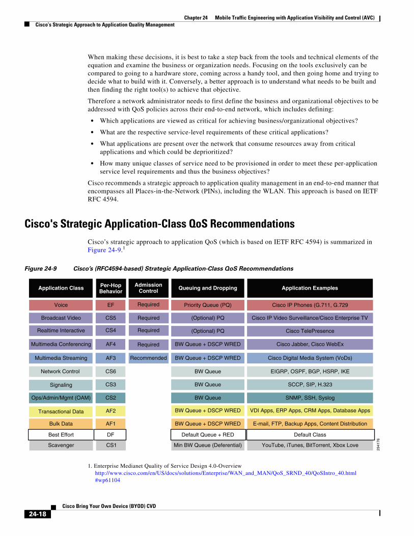
Cisco's Strategic Application-Class QoS RecommendationsCisco’s strategic approach to application QoS (which is based on IETF RFC 4594) is summarized in Figure 24-9.1
Figure 24-9 Cisco’s (RFC4594-based) Strategic Application-Class QoS Recommendations
1. Enterprise Medianet Quality of Service Design 4.0-Overview http://www.cisco.com/en/US/docs/solutions/Enterprise/WAN_and_MAN/QoS_SRND_40/QoSIntro_40.html#wp61104
2941
76
Application Class
Transactional Data AF2
Realtime Interactive CS4
Voice EF
Ops/Admin/Mgmt (OAM) CS2
Bulk Data AF1
Scavenger CS1
Network Control CS6
Multimedia Streaming AF3
Best Effort DF
Multimedia Conferencing AF4
Broadcast Video CS5
Signaling CS3
(Optional) PQ
BW Queue + DSCP WRED
BW Queue
BW Queue
BW Queue
BW Queue + DSCP WRED
(Optional) PQ
Priority Queue (PQ)
Queuing and Dropping
Min BW Queue (Deferential)
Required
Required
Required
Required
Recommended
AdmissionControl
Per-HopBehavior
BW Queue + DSCP WRED
BW Queue + DSCP WRED
Default Queue + RED
Cisco TelePresence
Cisco Digital Media System (VoDs)
EIGRP, OSPF, BGP, HSRP, IKE
SCCP, SIP, H.323
SNMP, SSH, Syslog
Cisco Jabber, Cisco WebEx
Cisco IP Video Surveillance/Cisco Enterprise TV
Cisco IP Phones (G.711, G.729
Application Examples
YouTube, iTunes, BitTorrent, Xbox Love
VDI Apps, ERP Apps, CRM Apps, Database Apps
E-mail, FTP, Backup Apps, Content Distribution
Default Class
24-18Cisco Bring Your Own Device (BYOD) CVD

Chapter 24 Mobile Traffic Engineering with Application Visibility and Control (AVC)Cisco’s Strategic Approach to Application Quality Management
Note Cisco has adopted RFC 4594 as its general DiffServ QoS strategy with the following exception: Cisco has swapped the marking recommendations of the RFC 4594 Broadcast Video class (of CS3) with the Signaling class (of CS5). Therefore Cisco has decided to mark Broadcast Video traffic as CS5 and Signaling traffic as CS3. This is primarily because Cisco has been marking Signaling to CS3 for over a decade (well before RFC 4594 was even drafted) and lacking a compelling business case to change the defaults on all its voice and video-telephony products, has decided to continue doing so. Furthermore, such a marking change would correspondingly force their customer base to change all their network QoS policies relating to the Signaling class as well. Therefore, Cisco has swapped these marking recommendations. It is important to remember that RFC 4594 is an informational RFC and not a standard and, as such, compliance-in full or in part-is not mandatory.
As shown in Figure 24-9, an enterprise may be required to support up to twelve application classes of that have unique service level requirements:
• Voice—This service class is intended for VoIP telephony (audio media only traffic-VoIP signaling traffic is assigned to the “Signaling” class). Traffic assigned to this class should be marked EF. This class is provisioned with an Expedited Forwarding (EF) Per-Hop Behavior (PHB). The EF PHB-defined in RFC 3246-is a strict-priority queuing service and, as such, admission to this class should be controlled (admission control is discussed in the following section). Example traffic includes G.711 and G.729a.
• Broadcast Video—This service class is intended for broadcast TV, live events, video surveillance flows, and similar “inelastic” streaming video flows (“inelastic” refers to flows that are highly drop sensitive and have no retransmission and/or flow control capabilities). Traffic in this class should be marked Class Selector 5 (CS5) and may be provisioned with an EF PHB; as such, admission to this class should be controlled. Example traffic includes live Cisco Digital Media System (DMS) streams to desktops or to Cisco Digital Media Players (DMPs), live Cisco Enterprise TV (ETV) streams, and Cisco IP Video Surveillance.
• Real-Time Interactive—This service class is intended for (inelastic) room-based, high-definition interactive video applications and is intended primarily for voice and video components of these applications. Whenever technically possible and administratively feasible, data sub-components of this class can be separated out and assigned to the “Transactional Data” traffic class. Traffic in this class should be marked CS4 and may be provisioned with an EF PHB; as such, admission to this class should be controlled. An example application is Cisco TelePresence.
• Multimedia Conferencing—This service class is intended for desktop software multimedia collaboration applications and is intended primarily for voice and video components of these applications. Whenever technically possible and administratively feasible, data sub-components of this class can be separated out and assigned to the “Transactional Data” traffic class. Traffic in this class should be marked Assured Forwarding (AF) Class 4 (AF41) and should be provisioned with a guaranteed bandwidth queue with DSCP-based Weighted-Random Early Detect (DSCP-WRED) enabled. Admission to this class should be controlled; additionally, traffic in this class may be subject to policing and re-marking. Example applications include Cisco Jabber and Cisco WebEx.
• Multimedia Streaming—This service class is intended for Video-on-Demand (VoD) streaming video flows which, in general, are more elastic than broadcast/live streaming flows. Traffic in this class should be marked AF Class 3 (AF31) and should be provisioned with a guaranteed bandwidth queue with DSCP-based WRED enabled. Admission control is recommended on this traffic class (though not strictly required) and this class may be subject to policing and re-marking. Example applications include Cisco Digital Media System Video-on-Demand (VoD) streams.
• Network Control—This service class is intended for network control plane traffic, which is required for reliable operation of the enterprise network. Traffic in this class should be marked CS6 and provisioned with a (moderate, but dedicated) guaranteed bandwidth queue. WRED should not be
24-19Cisco Bring Your Own Device (BYOD) CVD

Chapter 24 Mobile Traffic Engineering with Application Visibility and Control (AVC)Cisco’s Strategic Approach to Application Quality Management
enabled on this class, as network control traffic should not be dropped (if this class is experiencing drops, then the bandwidth allocated to it should be re-provisioned). Example traffic includes EIGRP, OSPF, BGP, HSRP, IKE, etc.
• Signaling—This service class is intended for signaling traffic that supports IP voice and video telephony. Traffic in this class should be marked CS3 and provisioned with a (moderate, but dedicated) guaranteed bandwidth queue. WRED should not be enabled on this class, as signaling traffic should not be dropped (if this class is experiencing drops, then the bandwidth allocated to it should be re-provisioned). Example traffic includes SCCP, SIP, H.323, etc.
• Operations/Administration/Management (OAM)—As the name implies, this service class is intended for network operations, administration, and management traffic. This class is critical to the ongoing maintenance and support of the network. Traffic in this class should be marked CS2 and provisioned with a (moderate, but dedicated) guaranteed bandwidth queue. WRED should not be enabled on this class, as OAM traffic should not be dropped (if this class is experiencing drops, then the bandwidth allocated to it should be re-provisioned). Example traffic includes SSH, SNMP, Syslog, etc.
• Transactional Data (or Low-Latency Data)—This service class is intended for interactive, “foreground” data applications (“foreground” refers to applications from which users are expecting a response—via the network—in order to continue with their tasks; excessive latency directly impacts user productivity). Traffic in this class should be marked AF Class 2 (AF21) and should be provisioned with a dedicated bandwidth queue with DSCP-WRED enabled. This traffic class may be subject to policing and re-marking. Example applications include data components of multimedia collaboration applications, Virtual Desktop Infrastructure (VDI) applications, Enterprise Resource Planning (ERP) applications, Customer Relationship Management (CRM) applications, database applications, etc.
• Bulk Data (or High-Throughput Data)—This service class is intended for non-interactive “background” data applications (“background” refers to applications from which users are not awaiting a response—via the network—in order to continue with their tasks; excessive latency in response times of background applications does not directly impact user productivity). Traffic in this class should be marked AF Class 1 (AF11) and should be provisioned with a dedicated bandwidth queue with DSCP-WRED enabled. This traffic class may be subject to policing and re-marking. Example applications include: email, backup operations, FTP/SFTP transfers, video and content distribution, etc.
• Best Effort (the default class)—This service class is the default class. The vast majority of applications will continue to default to this Best-Effort service class; as such, this default class should be adequately provisioned. Traffic in this class is marked Default Forwarding (DF or DSCP 0) and should be provisioned with a dedicated queue. WRED is recommended to be enabled on this class.
• Scavenger (or Low-Priority Data)—This service class is intended for non-business related traffic flows, such as data or video applications that are entertainment and/or gaming-oriented. The approach of a “less-than Best-Effort” service class for non-business applications (as opposed to shutting these down entirely) has proven to be a popular, political compromise. These applications are permitted on enterprise networks, as long as resources are always available for business-critical voice, video, and data applications. However, as soon as the network experiences congestion, this class is the first to be penalized and aggressively dropped. Traffic in this class should be marked CS1 and should be provisioned with a minimal bandwidth queue that is the first to starve should network congestion occur. Example traffic includes YouTube, Facebook, Xbox Live/360 Movies, iTunes, BitTorrent, etc.
24-20Cisco Bring Your Own Device (BYOD) CVD
Chapter 24 Mobile Traffic Engineering with Application Visibility and Control (AVC)Cisco’s Strategic Approach to Application Quality Management
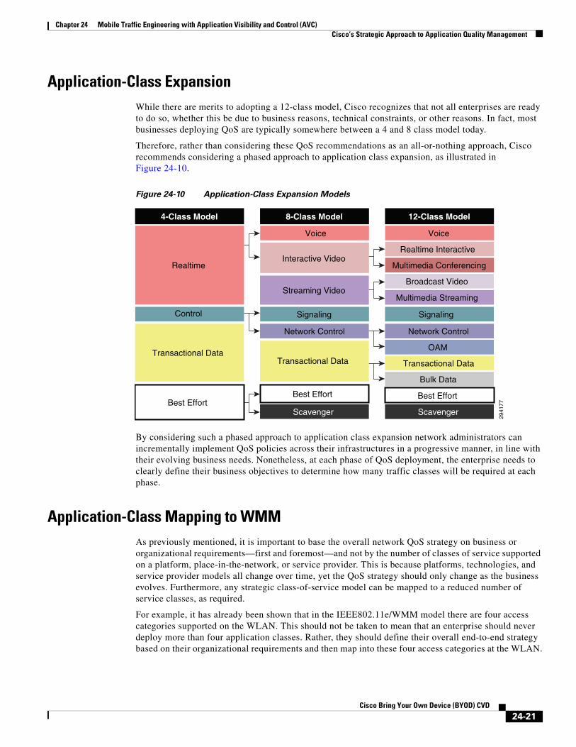
Application-Class ExpansionWhile there are merits to adopting a 12-class model, Cisco recognizes that not all enterprises are ready to do so, whether this be due to business reasons, technical constraints, or other reasons. In fact, most businesses deploying QoS are typically somewhere between a 4 and 8 class model today.
Therefore, rather than considering these QoS recommendations as an all-or-nothing approach, Cisco recommends considering a phased approach to application class expansion, as illustrated in Figure 24-10.
Figure 24-10 Application-Class Expansion Models
By considering such a phased approach to application class expansion network administrators can incrementally implement QoS policies across their infrastructures in a progressive manner, in line with their evolving business needs. Nonetheless, at each phase of QoS deployment, the enterprise needs to clearly define their business objectives to determine how many traffic classes will be required at each phase.
Application-Class Mapping to WMMAs previously mentioned, it is important to base the overall network QoS strategy on business or organizational requirements—first and foremost—and not by the number of classes of service supported on a platform, place-in-the-network, or service provider. This is because platforms, technologies, and service provider models all change over time, yet the QoS strategy should only change as the business evolves. Furthermore, any strategic class-of-service model can be mapped to a reduced number of service classes, as required.
For example, it has already been shown that in the IEEE802.11e/WMM model there are four access categories supported on the WLAN. This should not be taken to mean that an enterprise should never deploy more than four application classes. Rather, they should define their overall end-to-end strategy based on their organizational requirements and then map into these four access categories at the WLAN.
Transactional Data
Realtime
4-Class Model
Best Effort
Control Signaling
Transactional Data
Interactive Video
Voice
8-Class Model
Scavenger
Best Effort
Streaming Video
Network Control
OAM
Realtime Interactive
Transactional Data
Multimedia Conferencing
Voice
12-Class Model
Bulk Data
Scavenger
Best Effort
Multimedia Streaming
Network Control
Broadcast Video
Signaling
2941
77
24-21Cisco Bring Your Own Device (BYOD) CVD

Chapter 24 Mobile Traffic Engineering with Application Visibility and Control (AVC)Cisco 802.11e/802.1p/DSCP Mappings
Even highly complex models—such as an RFC 4594-based 12-class model—can be mapped into the four WMM access categories, as illustrated in Figure 24-11.
Figure 24-11 Example Twelve-Class Application-Class Model Mapped into WMM
Note Figure 24-11 serves only to illustrate the concept of application class mapping into a reduced set of traffic classes; additional details are provided later in this document to show best-practice recommendations in mapping a 4-Class model, an 8-Class model and this same 12-Class enterprise model into WMM.
Cisco 802.11e/802.1p/DSCP MappingsAt this point, it may be helpful to clarify some terms that will be used extensively throughout the rest of this paper:
• Downstream—Used to refer to the flow of packets from the wired network infrastructure to the wireless devices, including:
– Network Downstream—Refers to traffic leaving the WLC traveling to the AP; this traffic is encapsulated within LWAPP. Wired campus QoS policies provision downstream QoS.
– Radio Downstream—Refers to traffic leaving the AP and traveling to the WLAN clients. WMM provides downstream QoS for WLAN clients.
• Upstream—Used to indicate the flow of packets from the mobile wireless device to the wired network infrastructure, including:
– Radio Upstream—Refers to traffic transmitted by the WLAN clients and traveling to the AP. WMM provides upstream QoS for WLAN clients.
– Network upstream—Refers to traffic leaving the AP, traveling to the WLC; this traffic is encapsulated within LWAPP. Wired campus QoS policies provision upstream QoS.
2941
78
OAM
Realtime Interactive
Transactional Data
Multimedia Conferencing
Voice
12-Class StrategicApplication-Class Model
Bulk Data
Scavenger
Best Effort
Multimedia Streaming
Network Control
Broadcast Video
Signaling
Platinum
WMM Model(Cisco WLC Designations)
Silver
Gold
Bronze
24-22Cisco Bring Your Own Device (BYOD) CVD
Chapter 24 Mobile Traffic Engineering with Application Visibility and Control (AVC)Cisco 802.11e/802.1p/DSCP Mappings
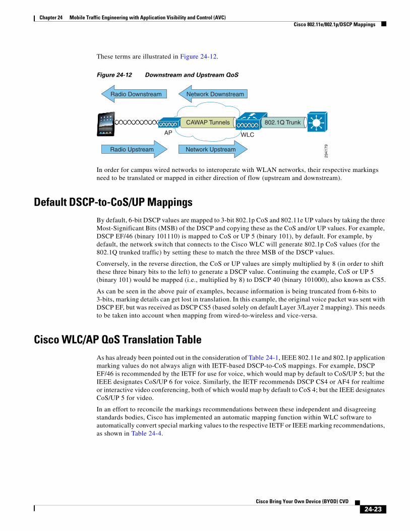
These terms are illustrated in Figure 24-12.
Figure 24-12 Downstream and Upstream QoS
In order for campus wired networks to interoperate with WLAN networks, their respective markings need to be translated or mapped in either direction of flow (upstream and downstream).
Default DSCP-to-CoS/UP MappingsBy default, 6-bit DSCP values are mapped to 3-bit 802.1p CoS and 802.11e UP values by taking the three Most-Significant Bits (MSB) of the DSCP and copying these as the CoS and/or UP values. For example, DSCP EF/46 (binary 101110) is mapped to CoS or UP 5 (binary 101), by default. For example, by default, the network switch that connects to the Cisco WLC will generate 802.1p CoS values (for the 802.1Q trunked traffic) by setting these to match the three MSB of the DSCP values.
Conversely, in the reverse direction, the CoS or UP values are simply multiplied by 8 (in order to shift these three binary bits to the left) to generate a DSCP value. Continuing the example, CoS or UP 5 (binary 101) would be mapped (i.e., multiplied by 8) to DSCP 40 (binary 101000), also known as CS5.
As can be seen in the above pair of examples, because information is being truncated from 6-bits to 3-bits, marking details can get lost in translation. In this example, the original voice packet was sent with DSCP EF, but was received as DSCP CS5 (based solely on default Layer 3/Layer 2 mapping). This needs to be taken into account when mapping from wired-to-wireless and vice-versa.
Cisco WLC/AP QoS Translation TableAs has already been pointed out in the consideration of Table 24-1, IEEE 802.11e and 802.1p application marking values do not always align with IETF-based DSCP-to-CoS mappings. For example, DSCP EF/46 is recommended by the IETF for use for voice, which would map by default to CoS/UP 5; but the IEEE designates CoS/UP 6 for voice. Similarly, the IETF recommends DSCP CS4 or AF4 for realtime or interactive video conferencing, both of which would map by default to CoS 4; but the IEEE designates CoS/UP 5 for video.
In an effort to reconcile the markings recommendations between these independent and disagreeing standards bodies, Cisco has implemented an automatic mapping function within WLC software to automatically convert special marking values to the respective IETF or IEEE marking recommendations, as shown in Table 24-4.
2941
79
Radio Downstream
Radio Upstream
AP WLC
Network Upstream
Network Downstream
CAWAP Tunnels 802.1Q Trunk
24-23Cisco Bring Your Own Device (BYOD) CVD

Chapter 24 Mobile Traffic Engineering with Application Visibility and Control (AVC)Cisco 802.11e/802.1p/DSCP Mappings
Residual DSCP-to-WMM MappingsThe IEEE 802.11e UP value for DSCP values that are not mentioned in the Table 5 are calculated by considering 3 MSB bits of DSCP. Thus with the exceptions noted in Table 5, DSCP values will map to the WMM/WLC Access Categories shown in Table 24-5.
WLC AVC/QoS Profile-to-DSCP MappingsIf QoS or AVC Profiles are created on a Cisco WLC and applied to WLANs, then the packets assigned to the access-categories within these profiles will be marked to the DSCP values shown in Table 24-6. For example, if an application is assigned to the Gold profile, then all application traffic will be marked to DSCP 34.
Table 24-4 Cisco WLC/AP DSCP-to-UP Translation Table1
1. Cisco Wireless LAN Controller WLAN Configuration Guide, Release 7.4 - Working with WLANs - Assigning QoS Profiles http://www.cisco.com/en/US/partner/docs/wireless/controller/7.4/configuration/guides/consolidated/b_cg74_CONSOLIDATED_chapter_01010111.html
Application Class IETF DSCP IEEE 802.11e UP WLC QoS Profile
Network control 56 (CS7) 7 Platinum
Internetwork control 48 (CS6) 7 Platinum
Voice 46 (EF) 6 Platinum
Multimedia Conferencing 34 (AF41) 5 Gold
Multimedia Streaming 26 (AF31) 4 Gold
Transactional Data 18 (AF21) 3 Silver
Bulk Data 10 (AF11) 2 Bronze
Best Effort 0 (BE) 0 Silver
Table 24-5 Default DSCP, UP and WLC Access Category Mappings (Excluding the Exceptions
Listed in Table 24-4)
DSCP Range IEEE 802.11e UP WLC QoS Profile
DSCPs 56-63 7 Platinum
DSCPs 48-55 6
DSCPs 40-47 5 Gold
DSCPs 32-39 4
DSCPs 24-31 3 Silver
DSCPs 0-7 0
DSCPs 16-23 2 Bronze
DSCPs 8-15 1
24-24Cisco Bring Your Own Device (BYOD) CVD

Chapter 24 Mobile Traffic Engineering with Application Visibility and Control (AVC)Cisco 802.11e/802.1p/DSCP Mappings
Cisco Wired-Wireless Mapping PointsWith the translation-mapping table and default mapping methods in place, the questions that remain are: where is mapping done between wired and wireless networks? And how?
Figure 24-13 is a very important diagram that identifies the various places where wired-and-wireless mapping takes place-in both the downstream direction (top of Figure 24-13) and the upstream direction (bottom of Figure 24-13).
Figure 24-13 Downstream and Upstream Layer 2/Layer 3 Mapping
In Figure 24-13, the following mappings occur in the downstream direction:
Step 1 The network switch maps the DSCP value of an incoming packet (destined to a WLAN via the WLC) to an 802.1p CoS value as it transits the 802.1Q trunks connecting to the WLC (by default this mapping is done by taking the three MSBs of the DSCP and copying these to the 802.1p CoS value).
Table 24-6 Default WLC Profile to DSCP Mappings
WLC QoS Profile DSCP
Platinum EF (DSCP 46)
Gold AF41 (DSCP 34)
Silver DF (DSCP 0)
Bronze AF11 (DSCP 10)
AP
AP
AP WLAN Controller
CAWAP Tunnels
UP DSCP Payload 802.1p DSCP Payload
802.1pDSCPPayload
DSCP DSCP Payload
DSCPDSCPPayload
CAPWAP Encapsulated Packet
CAPWAP Encapsulated Packet
Downstream
Upstream
2 13
54
2941
80
802.1Q Trunk
UPDSCPPayload
24-25Cisco Bring Your Own Device (BYOD) CVD

Chapter 24 Mobile Traffic Engineering with Application Visibility and Control (AVC)Configuring Downstream QoS Policies for Mobile Applications
Step 2 An 802.1Q frame/packet with an 802.1p marking and a DSCP marking arrive at the WLC. The DSCP of the packet is copied to the inner and outer DSCP fields of the CAPWAP packet on egress as it transits toward the destination APs and WLANs.
Note An exception will occur if the DSCP exceeds the Maximum Priority (i.e., the maximum DSCP marking value) defined in the QoS Profile associated with the destination WLAN, in which case both the inner and outer DSCP values will be marked down to this Maximum Priority value.
Step 3 The outer DSCP of the CAPWAP packet arriving at the AP will be mapped to an 802.11e UP marking based on the QoS Translation Table (Table 24-4) or a default mapping (if no explicit mapping is found for the specific DSCP value in the QoS Translation Table). The inner DSCP value is copied to the DSCP-field of the 802.11e frame/packet.
Conversely, in Figure 24-13, the following mappings occur in the upstream direction:
Step 1 The 802.11e UP values and DSCP values of a mobile application are marked in the software of the device as it is transmitted. When the frame/packet arrives at the AP, the UP value will be mapped to the outer DSCP value of the CAPWAP packet; this mapping is based on the QoS Translation Table (Table 24-4) or a default mapping (if no explicit mapping is found for the specific DSCP value in the QoS Translation Table). Additionally, the DSCP value set on the mobile device will be copied to the inner DSCP value of the CAPWAP packet.
Note As previously, the DSCP value assigned to the CAPWAP packet is subject to any Maximum Priority value capping that may be configured within the QoS Profile associated with the WLAN.
Step 2 The outer DSCP of the CAPWAP packet will be mapped to an 802.1p CoS value as the frame/packet leaves the WLC towards the wired network (by default this mapping is done by taking the three MSBs of the DSCP and copying these to the 802.1p CoS value). Additionally, the inner DSCP of the CAPWAP packet will be copied to the DSCP value of the 802.1Q trunked IP packet.
Configuring Downstream QoS Policies for Mobile ApplicationsProvisioning end-to-end mobile application QoS requires policy configuration at the following points in the wired and wireless networks for downstream flows:
• WLC AVC Profiles—Are configured and assigned to WLANs to identify applications and mark (with DSCP) or drop these packets. Additionally AVC Profiles assign applications to WMM access categories in the radio-downstream direction. AVC Profiles are applied on WLC ingress and are shown as point A in Figure 24-14.
• WLC QoS Profiles—Are assigned to each WLAN and define the (unicast and multicast) Default Priority (i.e., default/Best Effort DSCP value and access category) and the Maximum Priority value for the WLAN. QoS Profiles are applied on WLC egress and are shown as point B in Figure 24-14.
24-26Cisco Bring Your Own Device (BYOD) CVD

Chapter 24 Mobile Traffic Engineering with Application Visibility and Control (AVC)Configuring Downstream QoS Policies for Mobile Applications
• AP Access Switch QoS Policies—The entire underlying wired-network infrastructure should be configured with QoS policies in line with the strategic application-class model in use for the given enterprise. Additionally, the access-switch to which a given wireless access-point connects to may be used to work-around non-configurable upstream/downstream mapping operations (as is discussed in detail later); these policies are typically applied on access switch egress and are shown as point C in Figure 24-14.
Figure 24-14 Downstream QoS Policy Configuration Points in Wired/Wireless Networks
Wireless Controller QoS Profile GUI ConfigurationQoS Profiles—like AVC Profiles—are applied to both upstream and downstream flows on WLC egress. It is recommended to complete these steps to define an appropriate QoS Profile for a given WLAN. Among many other parameters, the WLAN QoS Profile defines:
• Per-User Bandwidth Contracts—(Optional) per-user limits for average and peak data and realtime traffic rates.
• Per-SSID Bandwidth Contracts—(Optional) per-SSID limits for average and peak data and realtime traffic rates.
• WLAN Maximum Priority—The highest DSCP marking value that may be used on the WLAN; this value can override AVC policies as well DSCP-values received from the wired network. As such, in multiservice WLANs, it is generally recommended to ensure that the Maximum Priority value be set to voice (i.e., platinum).
• Unicast and Multicast Default Priority—The default DSCP marking value to be used on the WLAN for all traffic not explicitly classified by an overriding AVC Profile. Typically these values are set as best effort (i.e., silver), however there may be cases where this default value may be set to background (i.e., bronze), which is discussed later in the Four-Class Model Mapping Configuration.
• Wired QoS Protocol—Can be set to 802.1p and the maximum CoS value can be defined per WLAN.
WLC QoS Profile GUI Configuration
Details of a given QoS Profile can be viewed and modified via the WLC GUI by performing the following steps:
1. Open a web browser to the WLC IP address via HTTPS and login.
2. Click the WIRELESS heading bar and expand the QoS link on the lower left and click Profiles.
3. Click the profile to be viewed/modified (these are listed in alphabetical order: bronze/gold/platinum/silver). Details of the Platinum QoS profile are shown in Figure 24-15.
2941
81
AP WLC WLCSwitch
Downstream
CAWAP Tunnels802.1Q Trunk
AB
C
AP AccessSwitch
24-27Cisco Bring Your Own Device (BYOD) CVD

Chapter 24 Mobile Traffic Engineering with Application Visibility and Control (AVC)Configuring Downstream QoS Policies for Mobile Applications
Figure 24-15 Viewing/Editing the Platinum WLC QoS Profile
To apply a QoS profile to a WLAN, complete the following steps.
1. Click the WLANs heading and select an existing WLAN (or click the CREATE NEW button to create a new one).
2. Click the QoS tab of the selected WLAN and ensure that:
a. Quality of Service (QoS) is set to PLATINUM (VOICE); this allows for the highest DSCP markings values to be used for AVC policies that are to be attached to the WLAN (in the following section).
b. Application Visibility checkbox is ENABLED, as shown in Figure 24-16.
3. Click Apply.
Note Applying a QoS policy to a WLAN will momentarily interrupt service.
24-28Cisco Bring Your Own Device (BYOD) CVD

Chapter 24 Mobile Traffic Engineering with Application Visibility and Control (AVC)Configuring Downstream QoS Policies for Mobile Applications
Figure 24-16 Assigning a QoS Profile to a WLAN and Enabling AVC
WLC QoS Profile CLI Configuration
The following CLI commands will apply the Platinum QoS Profile configuration to WLAN as well as enable AVC Visibility for the WLAN:
Example 24-1 Configuring QoS Profiles for WLANs and Enabling Application Visibility
(Cisco WLC) > config wlan disable 1 ! Disables the WLAN so that the QoS profile may be changed
(Cisco WLC) > config wlan qos 1 platinum ! Applies the Platinum QoS profile to the WLAN
(Cisco WLC) > config wlan avc 1 visibility enable ! Enables AVC Visibility on WLAn 1
(Cisco WLC) > config wlan enable 1 ! Re-enables WLAN 1
(Cisco WLC) >
This configuration can be verified with:
• show wlan (as shown in Example 24-2)
Example 24-2 QoS Profile Verification: show wlan
(Cisco WLC) >show wlan 1
WLAN Identifier.................................. 1Profile Name..................................... BYOD_EmployeeNetwork Name (SSID).............................. BYOD-EmployeeStatus........................................... Enabled
<snip>
24-29Cisco Bring Your Own Device (BYOD) CVD

Chapter 24 Mobile Traffic Engineering with Application Visibility and Control (AVC)Configuring Downstream QoS Policies for Mobile Applications
Quality of Service............................... Platinum
<snip>
AVC Visibilty.................................... Enabled
(Cisco WLC) >
Wireless Controller AVC QoS Profile ConfigurationAVC Profiles are applied to both upstream and downstream flows on WLC ingress. While this may simplify the QoS policy configuration on the WLC, it has design implications in upstream/downstream mapping, as has been previously discussed (and which is expanded on in the following sections).
Additionally, each WLAN can have only one AVC profile attached to it to control applications, however an AVC Profile can be attached to multiple WLANs. Also, an AVC Profile can contain a maximum of 32 application rules and a maximum of 16 AVC profiles can be created on a WLC.
Limitations of AVC on the WLC are as noted below and should be kept in mind while deploying AVC on WLC:
• IPv6 traffic or Multicast traffic cannot be classified.
• AVC is not supported on virtual WLC models.
• AVC is not supported on WLAN configured for Local Switching.
• AVC Profiles cannot be applied on a per controller, VLAN, or client basis (only WLAN).
• The AVC profiles do not support AAA override.
• NBAR based Rate Limiting per Application is not supported, however AVC will work with wireless Bi-Directional Rate Limiting (BDRL) per controller/interface/WLAN/user.
• Any application which is not classified/supported/recognized by the NBAR2 engine is captured as UNCLASSIFIED traffic.
As has been previously discussed, it also is important to note that each WLAN can have both a QoS Profile and an AVC Profile attached to it. The AVC Profile is applied when the packet enters the WLC and the QoS policy is applied when packet exits the WLC. If an AVC profile is mapped to WLAN with an explicit rule for a MARK action, that MARK action will override any default QoS Profile marking configured on the WLAN. However, QoS Profiles may define a Maximum Priority DSCP value for packet marking, which will override any AVC Profile marking policy. Thus care should be taken that QoS and AVC Profiles are correctly configured to complement-and not contradict-one another.
It may be helpful to begin by viewing the list of the over 1000 AVC supported applications by performing the following:
1. Select the Wireless heading and then expand the Application Visibility and Control link on the lower left.
2. Click the AVC Applications link and scroll through the alphabetical application list, as shown in Figure 24-17.
24-30Cisco Bring Your Own Device (BYOD) CVD

Chapter 24 Mobile Traffic Engineering with Application Visibility and Control (AVC)Configuring Downstream QoS Policies for Mobile Applications
Figure 24-17 AVC Application List
The 1039 AVC applications supported in WLC software version 7.4 are grouped into 16 Application Groups:
• Browsing
• Business-and-productivity-tools
• File-sharing
• Gaming
• Industrial-protocols
• Instant-messaging
• Internet-privacy
• Layer3-over-ip
• Location-based-services
• Net-admin
• Newsgroup
• Obsolete
• Other
24-31Cisco Bring Your Own Device (BYOD) CVD

Chapter 24 Mobile Traffic Engineering with Application Visibility and Control (AVC)Configuring Downstream QoS Policies for Mobile Applications
• Trojan
• Voice-and-video
Example 24-3 shows how to display a list of these applications via the WLC CLI.
Example 24-3 WLC CLI—Show AVC Applications
(Cisco WLC) > show avc applications
Application-Name App-ID Engine-ID Selector-ID Application-Group-Name ================ ====== ========= =========== ====================== 3com-amp3 538 3 629 other 3com-tsmux 977 3 106 obsolete 3pc 788 1 34 layer3-over-ip 914c/g 1109 3 211 net-admin 9pfs 479 3 564 net-admin acap 582 3 674 net-admin acas 939 3 62 other accessbuilder 662 3 888 other accessnetwork 607 3 699 other acp 513 3 599 other acr-nema 975 3 104 industrial-protocols …
AVC Protocol Packs (Featuring Cisco Jabber Support)
WLC software release 7.6 includes the ability to add modular AVC Protocol Packs. Protocol Packs are a means to distribute protocol updates outside the controller software release trains and can be loaded on the controller without replacing the controller software.
An AVC Protocol Pack is a single compressed file that contains multiple Protocol Description Language (PDL) files and a manifest file. A set of required protocols can be loaded, which helps AVC to recognize additional protocols for classification on your network. The manifest file gives information about the protocol pack, such as the protocol pack name, version, and some information about the available PDLs in the protocol pack.
The AVC Protocol Packs are released to specific AVC engine versions. You can load a protocol pack if the engine version on the controller platform is the same or higher than the version required by the protocol pack.
The first Protocol Pack to be supported on WLCs is AVC Protocol Pack 6.3 available at: http://software.cisco.com/download/release.html?mdfid=282600534&flowid=7012&softwareid=284509011&release=6.3.0&relind=AVAILABLE&rellifecycle=&reltype=latest
Note The AVC Protocol Pack feature is not supported on the Cisco 2500 Series Wireless LAN Controllers.
An AVC Protocol Pack can be downloaded to the the controller by entering these commands:
1. transfer download datatype avc-protocol-pack
2. transfer download start
Once downloaded, the version of the protocol pack that is used on the controller can be verified by the show avc protocol-pack version verification command (or within the GUI as shown in Figure 24-18).
One of the most notable applications to be supported in Protocol Pack 6.3 is Cisco Jabber. Various media subcomponents of the Cisco Jabber application that can be discretely identified by this AVC Protocol Pack include:
24-32Cisco Bring Your Own Device (BYOD) CVD
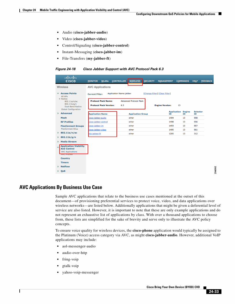
Chapter 24 Mobile Traffic Engineering with Application Visibility and Control (AVC)Configuring Downstream QoS Policies for Mobile Applications
• Audio (cisco-jabber-audio)
• Video (cisco-jabber-video)
• Control/Signaling (cisco-jabber-control)
• Instant-Messaging (cisco-jabber-im)
• File-Transfers (my-jabber-ft)
Figure 24-18 Cisco Jabber Support with AVC Protocol Pack 6.3
AVC Applications By Business Use Case
Sample AVC applications that relate to the business use cases mentioned at the outset of this document—of provisioning preferential services to protect voice, video, and data applications over wireless networks—are listed below. Additionally applications that might be given a deferential level of service are also listed. However, it is important to note that these are only example applications and do not represent an exhaustive list of applications by class. With over a thousand applications to choose from, these lists are simplified for the sake of brevity and serve only to illustrate the AVC policy concepts.
To ensure voice quality for wireless devices, the cisco-phone application would typically be assigned to the Platinum (Voice) access category via AVC, as might cisco-jabber-audio. However, additional VoIP applications may include:
• aol-messenger-audio
• audio-over-http
• fring-voip
• gtalk-voip
• yahoo-voip-messenger
24-33Cisco Bring Your Own Device (BYOD) CVD

Chapter 24 Mobile Traffic Engineering with Application Visibility and Control (AVC)Configuring Downstream QoS Policies for Mobile Applications
• yahoo-voip-over-sip
Similarly, to protect video and multimedia applications, the following applications might be assigned to the Gold (Video) access-category via AVC:
• cisco-ip-camera
• telepresence-media
• cisco-jabber-video
• webex-meeting
• ms-lync-media
• aol-messenger-video
• fring-video
• gtalk-video
• livemeeting
• msn-messenger-video
• rhapsody
• skype
• video-over-http
Note It may be that some of these video conferencing applications may be considered non-business in nature (such as Skype and gtalk-video), in which case these may be provisioned into the Bronze (Background) access category.
To deploy AVC policies to protect the signaling protocols relating to these voice and video applications, the following applications might be marked to the Call-Signaling marking of CS3 (DSCP 24) via AVC:
• sip
• sip-tls
• skinny
• telepresence-control
• cisco-jabber-control
• h323
• rtcp
To deploy policies to protect business-critical applications, the following applications might be marked AF21 (DSCP 18) via AVC:
• cisco-jabber-im
• citrix
• ms-lync
• ms-dynamics-crm-online
• salesforce
• sap
• oraclenames
24-34Cisco Bring Your Own Device (BYOD) CVD

Chapter 24 Mobile Traffic Engineering with Application Visibility and Control (AVC)Configuring Downstream QoS Policies for Mobile Applications
• perforce
• phonebook
• semantix
• synergy
On the other hand, some business applications would be best serviced in the background by assigning these to the Bronze (Background) access category via AVC:
• my-jabber-ft
• ftp/ftp-data/ftps-data
• cifs
• exchange
• notes
• smtp
• imap/secure imap
• pop3/secure pop3
• gmail
• hotmail
• yahoo-mail
And finally, many non-business applications can be controlled by either being assigned to the Bronze (Background) access category or dropped via AVC policies:
• youtube
• netflix
• bittorrent
• hulu
• itunes
• picasa
• call-of-duty
• doom
• directplay8
WLC AVC Profile GUI Configuration
To configure an AVC Profile (a set of AVC policies to be applied on a per-WLAN basis), perform the following steps:
1. Click the AVC Profiles link on the lower right.
2. Click the NEW button on the upper right to create a new AVC profile.
3. Name the new AVC profile and click the APPLY button, as shown in Figure 24-19.
24-35Cisco Bring Your Own Device (BYOD) CVD

Chapter 24 Mobile Traffic Engineering with Application Visibility and Control (AVC)Configuring Downstream QoS Policies for Mobile Applications
Figure 24-19 Creating an AVC Profile—Part 1
4. Click the name of the new AVC profile (which has become a link).
5. Click the ADD NEW RULE button on the upper right.
6. Select an Application Group to which the application to be controlled belongs.
7. Scroll down the Application List to specifically select the application to be controlled, as shown in Figure 24-20.
Figure 24-20 Creating an AVC Profile—Part 2
8. From the Action drop-down box select either DROP or MARK.
9. From the DSCP drop-down box select the WMM access category or a Custom DSCP marking for the application (as shown in Figure 24-21):
– Platinum (Voice)—Marks packets to DSCP EF/46.
– Gold (Video)—Marks packets to DSCP AF41/34.
24-36Cisco Bring Your Own Device (BYOD) CVD

Chapter 24 Mobile Traffic Engineering with Application Visibility and Control (AVC)Configuring Downstream QoS Policies for Mobile Applications
– Silver (Best Effort)—Marks packets to the default DSCP DF/0.
– Bronze (Background)—Marks packets to DSCP AF11/10.
– Custom [DSCP]—Allows for custom DSCP packet marking between 0 and 63.
Figure 24-21 Creating an AVC Profile—Part 3
10. Click the Apply button.
Note Applying a QoS policy to a WLAN will momentarily interrupt service.
Steps 4 through 10 can be repeated to add other applications to the AVC profile; up to 32 rules can be configured within an AVC profile.
Care should be taken to align DSCP marking policies with the enterprise strategic QoS model in use (4/8/12 class models).
Figure 24-22 shows an extended AVC profile that matches a 12-class model’s marking scheme and includes temporary markings for the Signaling class and the Transactional Data class.
24-37Cisco Bring Your Own Device (BYOD) CVD

Chapter 24 Mobile Traffic Engineering with Application Visibility and Control (AVC)Configuring Downstream QoS Policies for Mobile Applications
Figure 24-22 Creating an AVC Profile—Part 4
Once the AVC profile has been completed with all the applications to be classified (or the maximum of 32 applications has been reached), then complete the following steps to apply the profile to the WLAN.
1. Click the WLANS heading again.
2. Select the WLAN the AVC profile is to be applied to by clicking its WLAN ID link.
3. Click the QoS tab.
4. Select the AVC profile to be applied to the WLAN from the AVC Profile drop-down list, as shown in Figure 24-23.
24-38Cisco Bring Your Own Device (BYOD) CVD

Chapter 24 Mobile Traffic Engineering with Application Visibility and Control (AVC)Configuring Downstream QoS Policies for Mobile Applications
Figure 24-23 Attaching an AVC Profile to a WLAN
A WLAN can only have a single AVC profile applied to it, however AVC profiles may be applied to multiple WLANs.
WLC AVC Profile CLI Configuration
AVC profiles can also be created via the WLC CLI, as shown in Example 24-4.
Example 24-4 WLC CLI—AVC Profile Creation and Definition Example
! This section creates the "AVC-APPS" AVC profile(Cisco WLC) > config avc profile AVC-APPS create
! This section configures AVC for Voice ! Marking Cisco Phone + Cisco Jabber Audio as DSCP EF and assign to the Platinum WMM AC(Cisco WLC) > config avc profile AVC-APPS rule add application cisco-phone mark 46(Cisco WLC) > config avc profile AVC-APPS rule add application cisco-jabber-audio mark 46
! This section configures AVC for Multimedia Conferencing applications ! Marking these as DSCP AF41 and assigning them to the Gold WMM AC (Cisco WLC) > config avc profile AVC-APPS rule add application cisco-jabber-video mark 34(Cisco WLC) > config avc profile AVC-APPS rule add application webex-meeting mark 34
! This section configures AVC for Realtime Interactive applications ! Marking these as DSCP CS4 and assigning them to the Gold WMM AC (Cisco WLC) > config avc profile AVC-APPS rule add application telepresence-media mark 32
24-39Cisco Bring Your Own Device (BYOD) CVD

Chapter 24 Mobile Traffic Engineering with Application Visibility and Control (AVC)Configuring Downstream QoS Policies for Mobile Applications
! This section configures AVC for Signaling protocols ! Marking these to DSCP 24 and assigning them to the Gold WMM AC (Cisco WLC) > config avc profile AVC-APPS rule add application sip mark 24(Cisco WLC) > config avc profile AVC-APPS rule add application sip-tls mark 24(Cisco WLC) > config avc profile AVC-APPS rule add application h323 mark 24(Cisco WLC) > config avc profile AVC-APPS rule add application telepresence-control mark 24(Cisco WLC) > config avc profile AVC-APPS rule add application cisco-jabber-control mark 24
! This section configures AVC for Transactional Data applications ! Marking these to DSCP 18 and assigning them to the Gold WMM AC (Cisco WLC) > config avc profile AVC-APPS rule add application cisco-jabber-im mark 18(Cisco WLC) > config avc profile AVC-APPS rule add application citrix mark 18(Cisco WLC) > config avc profile AVC-APPS rule add application salesforce mark 18(Cisco WLC) > config avc profile AVC-APPS rule add application sap mark 18
! This section configures AVC for Bulk Data applications ! Marking these to DSCP AF11 and assigning them to the Bronze WMM AC (Cisco WLC) > config avc profile AVC-APPS rule add application my-jabber-ft mark 10(Cisco WLC) > config avc profile AVC-APPS rule add application ftp mark 10(Cisco WLC) > config avc profile AVC-APPS rule add application ftp-data mark 10(Cisco WLC) > config avc profile AVC-APPS rule add application ftps-data mark 10(Cisco WLC) > config avc profile AVC-APPS rule add application cifs mark 10(Cisco WLC) > config avc profile AVC-APPS rule add application exchange mark 10(Cisco WLC) > config avc profile AVC-APPS rule add application notes mark 10(Cisco WLC) > config avc profile AVC-APPS rule add application imap mark 10(Cisco WLC) > config avc profile AVC-APPS rule add application secure-imap mark 10
! This section configures AVC for Scavenger applications ! Marking these to DSCP CS8 and assigning them to the Bronze WMM AC (Cisco WLC) > config avc profile AVC-APPS rule add application facebook mark 8(Cisco WLC) > config avc profile AVC-APPS rule add application youtube mark 8(Cisco WLC) > config avc profile AVC-APPS rule add application netflix mark 8(Cisco WLC) > config avc profile AVC-APPS rule add application hulu mark 8(Cisco WLC) > config avc profile AVC-APPS rule add application skype mark 8(Cisco WLC) > config avc profile AVC-APPS rule add application msn-messenger-video mark 8(Cisco WLC) > config avc profile AVC-APPS rule add application bittorrent mark 8(Cisco WLC) > config avc profile AVC-APPS rule add application itunes mark 8(Cisco WLC) > config avc profile AVC-APPS rule add application call-of-duty mark 8
This configuration can be verified with:
• show avc profile summary (as shown in Example 24-5)
• show avc profile detailed (as shown in Example 24-6)
Example 24-5 AVC Profile Verification: show avc profile summary
(Cisco WLC) > show avc profile summary Profile-Name Number of Rules ============ ============== AVC-APPS 32(Cisco WLC) >
Example 24-6 AVC Profile Verification: show avc profile detailed
(Cisco WLC) > show avc profile detailed AVC-APPS
Application-Name Application-Group-Name Action DSCP ================ ======================= ====== ====
24-40Cisco Bring Your Own Device (BYOD) CVD
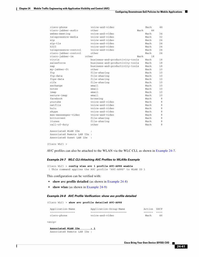
Chapter 24 Mobile Traffic Engineering with Application Visibility and Control (AVC)Configuring Downstream QoS Policies for Mobile Applications
cisco-phone voice-and-video Mark 46 cisco-jabber-audio other Mark 46 webex-meeting voice-and-video Mark 34 telepresence-media voice-and-video Mark 32 sip voice-and-video Mark 24 sip-tls voice-and-video Mark 24 h323 voice-and-video Mark 24 telepresence-control voice-and-video Mark 24 cisco-jabber-control other Mark 24 cisco-jabber-im other Mark 18 citrix business-and-productivity-tools Mark 18 salesforce business-and-productivity-tools Mark 18 sap business-and-productivity-tools Mark 18 my-jabber-ft other Mark 10 ftp file-sharing Mark 10 ftp-data file-sharing Mark 10 ftps-data file-sharing Mark 10 cifs file-sharing Mark 10 exchange email Mark 10 notes email Mark 10 imap email Mark 10 secure-imap email Mark 10 facebook browsing Mark 8 youtube voice-and-video Mark 8 netflix voice-and-video Mark 8 hulu voice-and-video Mark 8 skype voice-and-video Mark 8 msn-messenger-video voice-and-video Mark 8 bittorrent file-sharing Mark 8 itunes file-sharing Mark 8 call-of-duty other Mark 8
Associated WLAN IDs : Associated Remote LAN IDs : Associated Guest LAN IDs :
(Cisco WLC) >
AVC profiles can also be attached to the WLAN via the WLC CLI, as shown in Example 24-7.
Example 24-7 WLC CLI-Attaching AVC Profiles to WLANs Example
(Cisco WLC) > config wlan avc 1 profile AVC-APPS enable ! This command applies the AVC profile "AVC-APPS" to WLAN ID 1
This configuration can be verified with:
• show avc profile detailed (as shown in Example 24-8)
• show wlan (as shown in Example 24-9)
Example 24-8 AVC Profile Verification: show avc profile detailed
(Cisco WLC) > show avc profile detailed AVC-APPS
Application-Name Application-Group-Name Action DSCP ================ ======================= ====== ==== cisco-phone voice-and-video Mark 46
<snip>
Associated WLAN IDs : 1 Associated Remote LAN IDs :
24-41Cisco Bring Your Own Device (BYOD) CVD
Chapter 24 Mobile Traffic Engineering with Application Visibility and Control (AVC)Configuring Downstream QoS Policies for Mobile Applications
Associated Guest LAN IDs :
(Cisco WLC) >
Example 24-9 AVC Profile Verification: show wlan
(Cisco WLC) >show wlan 1
WLAN Identifier.................................. 1Profile Name..................................... BYOD_EmployeeNetwork Name (SSID).............................. BYOD-EmployeeStatus........................................... Enabled
<snip>
Quality of Service............................... Platinum
<snip>
AVC Visibilty.................................... EnabledAVC Profile Name................................. AVC-APPS
(Cisco WLC) >
AP Access Switch Downstream QoS PoliciesThe purpose of network QoS policies is to ensure that enterprise application classes will map into the correct WMM access categories (and vice versa). Since the admission to the WMM access categories is based on 802.11e UP values, which in turn are based on DSCP-to-UP translations (as covered in Step 3 of Figure 24-13), the packets need to enter the AP with the necessary (outer) DSCP values (of the CAPWAP packet) to achieve the desired mappings. This requirement is underscored by the fact that the WLC/AP QoS Translation Table (Table 24-4) is not modifiable and neither is the default DSCP-to-CoS/UP mapping (Table 24-5). Therefore the final point that an administrator could correctly set (or reset) DSCP values in packets before handing these off to the AP to ensure the traffic is placed in the desired WMM access category is at the egress interface of the network access switch to which the AP is connected (shown as point C in Figure 24-14).
Note Granted, it would be possible to perform DSCP remarking within the Cisco WLC via an AVC policy. Such an AVC policy would match on an application type(s) and then set this to a differing DSCP value as used in the enterprise campus network. However AVC policies apply in both directions simultaneously (and there is no option to apply these in the downstream or upstream direction only). Therefore such an AVC policy—intended for downstream remarking—would include the undesired effect of marking these application types incompatibly with the enterprise models for traffic in the upstream direction towards the wired network.
The details of the network downstream DSCP remarking policy will vary according to the enterprise application-class models in use. To illustrate a cross-section of marking-model variations—as well as Catalyst switching platform variations—the following mappings examples will be considered in detail:
• Four-class enterprise model mapped to WMM on a Catalyst 3750-X series switch (Four-Class Enterprise to WMM Mapping Model)
• Eight-class enterprise model mapped to WMM on a Catalyst 4500E series switch with Supervisor 7-E (Eight-Class Enterprise to WMM Mapping Model)
24-42Cisco Bring Your Own Device (BYOD) CVD

Chapter 24 Mobile Traffic Engineering with Application Visibility and Control (AVC)Configuring Downstream QoS Policies for Mobile Applications
• Twelve-class enterprise model mapped to WMM on a Catalyst 6500 series switch with Supervisor 2T (Twelve-Class Enterprise to WMM Mapping Model)
Four-Class Enterprise to WMM Mapping Model
If the enterprise has deployed a four-class strategic model, then this allows for a 1:1 mapping into the four WMM access categories. The default mapping for a four-class enterprise model to WMM is shown in Figure 24-24.
Figure 24-24 Default Downstream Four-Class Enterprise Model Mapping to WMM
As can be seen in Figure 24-24, if the QoS Translation Table (Table 24-4) and default mappings (Table 24-5) were applied on these four enterprise QoS classes, these would map to only two access categories: Platinum (Voice) and Silver (Best Effort). The remaining two access categories would not even be used. While this default mapping will ensure voice quality, no other application will benefit from wireless QoS.
An alternative approach would be to perform remarking at the network access switch (connecting to the wireless AP) at the egress interface in the outbound direction such that the Control/Signaling application class is remarked to a DSCP value that will map to an UP value (on the AP) that will, in turn, be assigned to the Gold WMM AC. Similarly, Best Effort traffic may be mapped to a DSCP value that will map to an UP value that will, in turn, be assigned to the Bronze WMM AC. This re-mapping approach would then leave the Silver WMM AC to exclusively service Transactional Data applications and thereby reflect the same overall relative priority of servicing as the original model. The modified four-class mapping model is shown in Figure 24-26.
Perhaps the question may arise: why not just configure an AVC policy on the WLC to match signaling traffic and remark it to a DSCP value that will map to the Gold WMM AC—like say CS4/DSCP 32—rather than configuring mapping policies on the access switch? To answer this, it should be kept in mind that such an AVC marking policy on the WLC—which operates both in the upstream and downstream direction—will interfere with QoS policies on the rest of the wired network (which includes both the upstream network as well as the transit network between the WLC and the APs). Specifically, while such a policy may achieve the intended result in the downstream direction, it will include the
2941
90
Transactional Data
Realtime
4-Class StrategicEnterprise Model
Best Effort
Control
PlatinumUP 7
UP 6
WMM Model +802.11e User Priority
Silver
Gold
Bronze
AF2
EF
DSCP
CS3UP 5
UP 4
UP 3
UP 0
UP 2
UP 1DF
24-43Cisco Bring Your Own Device (BYOD) CVD

Chapter 24 Mobile Traffic Engineering with Application Visibility and Control (AVC)Configuring Downstream QoS Policies for Mobile Applications
unintended effect of marking signaling to CS4 (rather than CS3) in the upstream direction also, which would be incompatible with the rest of the enterprise strategic policy and would have to be remapped at the WLC upstream switch. Furthermore, Signaling traffic marked on the WLC to CS4 by AVC and transiting in the downstream direction would have no QoS applied over the wired network between the WLC and the APs unless the administrator modified all the policies in the path to accommodate. Therefore, a much simpler approach to achieve the same end result is to include a simple remarking policy on the final access switch connecting to the AP.
However, rather than remapping signaling traffic to a code-point that may be used for another application, it may be better to remark signaling to a non-standard codepoint for this one-time operation, such as DSCP 33. DSCP 33 would map (by default) to the Gold WMM AC and would uniquely identify this remapped signaling traffic.
Similarly the default Best Effort class could be remapped on the network access switch to a non-standard codepoint that would be assigned to the Bronze WMM AC-such as DSCP 9. However, some platforms, such as the Catalyst 3750, do not support egress marking policies and only support marking/remarking/DSCP-mutation policies on ingress. In such a case, remarking Best Effort traffic on access switch ingress will affect BE marking on all interfaces and not just the interface connecting to the access point.
In such a case, a more elegant method would be to modify the QoS Profile for the WLAN so that the Unicast/Multicast Default Priority for the WLAN is set to Background instead of Best Effort, as shown in Figure 24-25.
Figure 24-25 Modifying the Platinum WLC QoS Profile-Best Effort 'Background
It bears noting that assigning the default class to the Background WMM category will marginally delay best effort traffic, however this is the nature of QoS as there is always a tradeoff. In this scenario, this is the necessary cost of providing superior levels of service to the signaling and transactional data application classes, thus providing the four levels of service required to meet their strategic business objectives of QoS.
The modified mapping of a four-class enterprise model to WMM is shown in Figure 24-26.
24-44Cisco Bring Your Own Device (BYOD) CVD

Chapter 24 Mobile Traffic Engineering with Application Visibility and Control (AVC)Configuring Downstream QoS Policies for Mobile Applications
Figure 24-26 Modified Downstream Four-Class Enterprise Model Mapping to WMM
Catalyst 3750 Configuration Example
To highlight platform-specific syntax, features, and limitations, each mapping model is presented on a different Catalyst switching platform. This four-class enterprise mapping to WMM AC is presented on the Catalyst 3750 (which will be identical to configuration for the Catalyst 2960 and 3560 switches also).
As noted, the Catalyst 3750 does not support egress remarking; only ingress marking or ingress DSCP-mutation are supported, as shown in Figure 24-27.
2941
92
Transactional Data
Realtime
4-Class StrategicEnterprise Model
Best Effort
Control
PlatinumUP 7
UP 6
WMM Model +802.11e User Priority
Silver
Gold
Bronze
AF2
EF
DSCP
CS3 DSCP 33UP 5
UP 4
UP 3
UP 0
UP 2
UP 1DF
24-45Cisco Bring Your Own Device (BYOD) CVD

Chapter 24 Mobile Traffic Engineering with Application Visibility and Control (AVC)Configuring Downstream QoS Policies for Mobile Applications
Figure 24-27 Catalyst 3750 Four-Class Enterprise to WMM Marking and Mapping Policies
The Catalyst 3750 employs Multilayer Switch QoS (MLS QoS), and as such DSCP-remarking policies can be configured in one of two ways:
• Class-based marking policy (as shown in Example 24-10)
• DSCP-Mutation (as shown in Example 24-11)
Example 24-10 Catalyst 3750 Downstream Four-Class Enterprise Model Mapping Policy to WMM via
Class-Based Marking
! This section configures the class-mapC3750-X(config-cmap)# class-map match-all SIGNALINGC3750-X(config-cmap)# match ip dscp cs3 ! Signaling traffic is matched on DSCP CS3
! This section configures the Network Downstream Remarking policy-mapC3750-X(config-cmap)# policy-map DOWNSTREAM-WMM-REMARKINGC3750-X(config-pmap-c)# class SIGNALINGC3750-X(config-pmap-c)# set dscp 33 ! Signaling is remarked DSCP 33 to map into WMM Gold downstream
! This section attaches the Downstream policy to the campus-side interfaceC3750-X(config)# interface TenGigabitEthernet2/1/1C3750-X(config-if)# mls qos trust dscp ! Configures the port to statically trust DSCP on ingressC3750-X(config-if)# service-policy input DOWNSTREAM-WMM-REMARKING ! Attaches the Downstream DSCP remarking policy to the interface on ingress
This configuration can be verified with the commands:
• show mls qos interface
• show class-map
• show policy-map
2941
93
AP WLC WLCSwitch
Downstream
CAWAP Tunnels802.1Q Trunk
AB
D
E
C
AVC PolicySignaling Protocols are markedCS3 in both directions
AP DSCP-to-UP/WMM MappingDSCP 33 is mapped to UP 4 and Gold AC
QoS ProfileBest Effort is mapped toBackground WMM AC
Catalyst 3750 Egress QueuingDSCP 33 is mapped to same egress queue as CS3
Catalyst 3750 Remarking/DSCP-MutationCS3 is remarked/mutated toDSCP 33 on ingress
Catalyst 3750Access Switch
24-46Cisco Bring Your Own Device (BYOD) CVD

Chapter 24 Mobile Traffic Engineering with Application Visibility and Control (AVC)Configuring Downstream QoS Policies for Mobile Applications
• show policy-map interface
Example 24-11 Downstream Four-Class Enterprise Model Mapping Policy to WMM via DSCP-Mutation
! This section configures the Downstream DSCP Mutation mapC3750-X(config)# mls qos map dscp-mutation DOWNSTREAM-WMM-MUTATION 24 to 33
! This section attaches the Downstream policy to the campus-side interfaceC3750-X(config)# interface TenGigabitEthernet2/1/1C3750-X(config-if)# mls qos trust dscp ! Configures the port to statically trust DSCP on ingressC3750-X(config-if)# mls qos dscp-mutation DOWNSTREAM-WMM-MUTATION ! Attaches the Downstream DSCP mutation map to the interface on ingress
This configuration can be verified with the commands:
• show mls qos interface
• show mls qos maps dscp-mutation
Additionally, this non-standard DSCP representing signaling traffic should be mapped to the same egress queue as regular signaling traffic (marked CS3), as shown in Example 24-12.
Example 24-12 Catalyst 3750 Egress Queuing Configuration
! This section configures buffers and thresholds on Q1 through Q4C3750(config)# mls qos queue-set output 1 buffers 15 30 35 20 ! Queue buffers are allocatedC3750(config)# mls qos queue-set output 1 threshold 1 100 100 100 100 ! All Q1 (PQ) Thresholds are set to 100%C3750(config)# mls qos queue-set output 1 threshold 2 80 90 100 400 ! Q2T1 is set to 80%; Q2T2 is set to 90%; ! Q2 Reserve Threshold is set to 100%; ! Q2 Maximum (Overflow) Threshold is set to 400%C3750(config)# mls qos queue-set output 1 threshold 3 100 100 100 400 ! Q3T1 is set to 100%, as all packets are marked the same weight in Q3 ! Q3 Reserve Threshold is set to 100%; ! Q3 Maximum (Overflow) Threshold is set to 400%C3750(config)# mls qos queue-set output 1 threshold 4 60 100 100 400 ! Q4T1 is set to 60%; Q4T2 is set to 100% ! Q4 Reserve Threshold is set to 100%; ! Q4 Maximum (Overflow) Threshold is set to 400% ! This section configures egress CoS-to-Queue mappings (if required)C3750(config)# mls qos srr-queue output cos-map queue 1 threshold 3 4 5 ! CoS 4 and 5 are mapped to egress Q1T3 (the tail of the PQ)C3750(config)# mls qos srr-queue output cos-map queue 2 threshold 1 2 ! CoS 2 is mapped to egress Q2T1C3750(config)#mls qos srr-queue output cos-map queue 2 threshold 2 3 ! CoS 3 is mapped to egress Q2T2C3750(config)# mls qos srr-queue output cos-map queue 2 threshold 3 6 7 ! CoS 6 and 7 are mapped to Q2T3C3750(config)# mls qos srr-queue output cos-map queue 3 threshold 3 0 ! CoS 0 is mapped to Q3T3 (the tail of the default queue)C3750(config)# mls qos srr-queue output cos-map queue 4 threshold 3 1 ! CoS 1 is mapped to Q4T3 (tail of the less-than-best-effort queue)
! This section configures egress DSCP-to-Queue mappingsC3750(config)# mls qos srr-queue output dscp-map queue 1 threshold 3 32 40 46 ! DSCP CS4, CS5 and EF are mapped to egress Q1T3 (tail of the PQ)C3750(config)# mls qos srr-queue output dscp-map queue 2 threshold 1 16 18 20 22 ! DSCP CS2 and AF2 are mapped to egress Q2T1
24-47Cisco Bring Your Own Device (BYOD) CVD

Chapter 24 Mobile Traffic Engineering with Application Visibility and Control (AVC)Configuring Downstream QoS Policies for Mobile Applications
C3750(config)# mls qos srr-queue output dscp-map queue 2 threshold 1 26 28 30 34 36 38 ! DSCP AF3 and AF4 are mapped to egress Q2T1C3750(config)# mls qos srr-queue output dscp-map queue 2 threshold 2 24 33 ! DSCP CS3 and DSCP 33 is mapped to egress Q2T2C3750(config)# mls qos srr-queue output dscp-map queue 2 threshold 3 48 56 ! DSCP CS6 and CS7 are mapped to egress Q2T3C3750(config)# mls qos srr-queue output dscp-map queue 3 threshold 3 0 ! DSCP DF is mapped to egress Q3T3 (tail of the best effort queue)C3750(config)# mls qos srr-queue output dscp-map queue 4 threshold 1 8 ! DSCP CS1 is mapped to egress Q4T1C3750(config)# mls qos srr-queue output dscp-map queue 4 threshold 2 10 12 14 ! DSCP AF1 is mapped to Q4T3 (tail of the less-than-best-effort queue)
! This section configures interface egress queuing parametersC3750(config)# interface range GigabitEthernet1/0/1-48C3750(config-if-range)# queue-set 1 ! The interface(s) is assigned to queue-set 1C3750(config-if-range)# srr-queue bandwidth share 1 30 35 5 ! The SRR sharing weights are set to allocate 30% BW to Q2 ! 35% BW to Q3 and 5% BW to Q4 ! Q1 SRR sharing weight is ignored, as it will be configured as a PQC3750(config-if-range)# priority-queue out ! Q1 is enabled as a strict priority queue
This configuration can be verified with the commands:
• show mls qos queue-set
• show mls qos maps cos-output-q
• show mls qos maps dscp-output-q
• show mls qos interface interface x/y queueing
• show mls qos interface interface x/y statistics
Note Additional design recommendations for the Catalyst 3750 can be found in the Medianet Campus QoS Design 4.0 design chapter at: http://www.cisco.com/en/US/docs/solutions/Enterprise/WAN_and_MAN/QoS_SRND_40/QoSCampus_40.html#wp1099462.
Eight-Class Enterprise to WMM Mapping Model
If the enterprise has deployed an eight-class strategic model, then a simple 1:1 mapping is no longer possible and some additional considerations need to be taken into account.
One such consideration is whether all eight traffic classes will have application traffic generated to and/or from wireless mobile devices. For example, no mobile clients or devices should be transmitting or receiving Network Control traffic (as this application class is intended for servicing the control plane requirements of the network infrastructure).
Note It also can be argued that no Streaming Video traffic should be sourced from mobile devices (although these devices might be receivers of such streams). Nonetheless, since traffic for this class may be present—primarily in the downstream direction—and as such will be included in the mapping model (albeit with a dashed line to indicate that this application traffic is typically unidirectional in the downstream direction only).
24-48Cisco Bring Your Own Device (BYOD) CVD

Chapter 24 Mobile Traffic Engineering with Application Visibility and Control (AVC)Configuring Downstream QoS Policies for Mobile Applications
The default mapping for a four-class enterprise model to WMM is shown in Figure 24-28.
Figure 24-28 Default Downstream Eight-Class Enterprise Model Mapping to WMM
While this default Eight-Class mapping may be adequate for some environments, it should be noted that there is no QoS provisioned for Transactional Data traffic (that may include VDI applications like Citrix XenDesktop or VMware View) nor for Signaling traffic (which is control plane traffic for IP telephone and/or IP video telephony applications)—other than merely protecting these application classes from Scavenger traffic.
Therefore, it may be desirable to remap these applications to the Gold access-category, using non-standard codepoints (as in the previous example). In this case, Signaling traffic can again be mapped to DSCP 33 and Transactional Data can be mapped to DSCP 35 at the AP access switch in the egress direction,
Note As both DSCP 33 and 35 map to the same UP value of 4, there is no advantage/disadvantage to marking these applications to a higher/lower DSCP value, provided these maps to the desired WMM AC. The key is keeping these values unique and distinct for traffic management purposes.
The modified eight-class mapping model is shown in Figure 24-29.
2941
94
Transactional Data
Interactive Video
Voice
8-Class StrategicEnterprise Model
Scavenger
Best Effort
Streaming Video
Network Control
Signaling
PlatinumUP 7
UP 6
WMM Model +802.11e User Priority
Silver
Gold
Bronze
CS4
AF2
AF4
EF
DSCP
CS1
BE
CS0
CS3
UP 5
UP 4
UP 3
UP 0
UP 2
UP 1
24-49Cisco Bring Your Own Device (BYOD) CVD
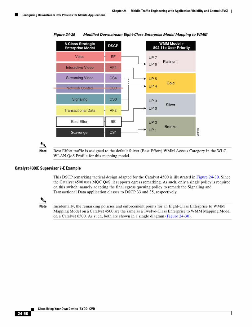
Chapter 24 Mobile Traffic Engineering with Application Visibility and Control (AVC)Configuring Downstream QoS Policies for Mobile Applications
Figure 24-29 Modified Downstream Eight-Class Enterprise Model Mapping to WMM
Note Best Effort traffic is assigned to the default Silver (Best Effort) WMM Access Category in the WLC WLAN QoS Profile for this mapping model.
Catalyst 4500E Supervisor 7-E Example
This DSCP remarking tactical design adapted for the Catalyst 4500 is illustrated in Figure 24-30. Since the Catalyst 4500 uses MQC QoS, it supports egress remarking. As such, only a single policy is required on this switch: namely adapting the final egress queuing policy to remark the Signaling and Transactional Data application classes to DSCP 33 and 35, respectively.
Note Incidentally, the remarking policies and enforcement points for an Eight-Class Enterprise to WMM Mapping Model on a Catalyst 4500 are the same as a Twelve-Class Enterprise to WMM Mapping Model on a Catalyst 6500. As such, both are shown in a single diagram (Figure 24-30).
2941
95
Transactional Data
Interactive Video
Voice
8-Class StrategicEnterprise Model
Scavenger
Best Effort
Streaming Video
Network Control
Signaling
PlatinumUP 7
UP 6
WMM Model +802.11e User Priority
Silver
Gold
Bronze
CS4
AF2
AF4
EF
DSCP
CS1
BE
CS0
CS3
UP 5
UP 4
UP 3
UP 0
UP 2
UP 1
24-50Cisco Bring Your Own Device (BYOD) CVD

Chapter 24 Mobile Traffic Engineering with Application Visibility and Control (AVC)Configuring Downstream QoS Policies for Mobile Applications
Figure 24-30 Catalyst 4500/6500 Eight-Class/Twelve-Class Enterprise to WMM Marking and
Mapping Policies
This modified eight-class mapping configuration example is presented on the Catalyst 4500-E series switch (with Supervisor 7-E), as shown in Example 24-13. Since MQC only supports one service-policy statement attached to a given interface in a single direction, the egress remarking policy must be combined with the (eight-class) egress queuing policy as a single MQC service-policy in the output direction, as shown in Example 24-13.
Example 24-13 Catalyst 4500 Downstream Eight-Class Enterprise Model Queuing and Mapping Policy
to WMM
! This section configures the class-maps for the egress queuing policyC4500(config)# class-map match-any PRIORITY-QUEUEC4500(config-cmap)# match dscp ef ! VoIP (EF) is mapped to the PQC4500(config)# class-map match-all INTERACTIVE-VIDEO-QUEUEC4500(config-cmap)# match dscp af41 af42 af43 ! Interactive-Video (AF4) is assigned a dedicated queueC4500(config)# class-map match-all STREAMING-VIDEO-QUEUEC4500(config-cmap)# match dscp af31 af32 af33 ! Streaming-Video (AF3) is assigned a dedicated queueC4500(config)# class-map match-any CONTROL-QUEUEC4500(config-cmap)# match dscp cs6 ! Network Control (CS6) is mapped to a dedicated queueC4500(config)# class-map match-any SIGNALING-QUEUEC4500(config-cmap)# match dscp cs3 ! Signaling (CS3) is mapped to a dedicated queueC4500(config)# class-map match-all TRANSACTIONAL-DATA-QUEUEC4500(config-cmap)# match dscp af21 af22 af23 ! Transactional Data (AF2) is assigned a dedicated queueC4500(config)# class-map match-all SCAVENGER-QUEUEC4500(config-cmap)# match dscp cs1 ! Scavenger (CS1) is assigned a dedicated queue
! This section configures the 1P7Q1T+DBL egress queuing policy-mapC4500(config)# policy-map 1P7Q1T+DBL+DOWNSTREAM-MAPPINGC4500(config-pmap-c)# class PRIORITY-QUEUEC4500(config-pmap-c)# priority
2941
96
AP WLC WLCSwitch
Downstream
CAWAP Tunnels802.1Q Trunk
ABD
AP DSCP-to-UP/WMM MappingDSCP 33 is mapped to UP 4 and Gold AC
QoS ProfileBest Effort is mapped toSilver WMM AC
Catalyst 4500/6500 Access Switch
C
Catalyst 4500 Egress Queuing and RemarkingCS3 is mapped to egress queue and remarked DSCP 33AF21 is mapped to egress queue and remarked to DSCP 35
AVC PolicySignaling Protocols are markedCS3 in both directions
24-51Cisco Bring Your Own Device (BYOD) CVD

Chapter 24 Mobile Traffic Engineering with Application Visibility and Control (AVC)Configuring Downstream QoS Policies for Mobile Applications
! Defines a priority queueC4500(config-pmap-c)# class INTERACTIVE-VIDEO-QUEUEC4500(config-pmap-c)# bandwidth remaining percent 23C4500(config-pmap-c)# dbl ! Defines a interactive-video queue with 23% BW remaining + DBLC4500(config-pmap-c)# class STREAMING-VIDEO-QUEUEC4500(config-pmap-c)# bandwidth remaining percent 10C4500(config-pmap-c)# dbl ! Defines a streaming-video queue with 10% BW remaining + DBLC4500(config-pmap-c)# class CONTROL-QUEUEC4500(config-pmap-c)# bandwidth remaining percent 5 ! Defines a control/management queue with 5% BW remainingC4500(config-pmap-c)# class SIGNALING-QUEUEC4500(config-pmap-c)# bandwidth remaining percent 2 ! Defines a signaling queue with 2% BW remainingC4500(config-pmap-c)# set dscp 33 ! Remarks signaling traffic to DSCP 33 for WMM Gold downstream mappingC4500(config-pmap-c)# class TRANSACTIONAL-DATA-QUEUEC4500(config-pmap-c)# bandwidth remaining percent 24C4500(config-pmap-c)# dbl ! Defines a transactional data queue with 24% BW remaining + DBLC4500(config-pmap-c)# set dscp 35 ! Remarks transactional data to DSCP 35 for WMM Gold downstream mappingC4500(config-pmap-c)# class SCAVENGER-QUEUEC4500(config-pmap-c)# bandwidth remaining percent 1 ! Defines a (minimal) scavenger queue with 1% BW remaining/limitC4500(config-pmap-c)# class class-defaultC4500(config-pmap-c)# bandwidth remaining percent 25C4500(config-pmap-c)# dbl ! Provisions the default/Best Effort queue with 25% BW remaining + DBL
! This section attaches the egress queuing & mapping policy to AP interfaceC4500(config)# interface GigabitEthernet 3/1C4500(config-if)# service-policy output 1P7Q1T+DBL+DOWNSTREAM-MAPPING ! Attaches the combined egress queuing and egress remarking policy to the int
Note Additional detail on Catalyst 4500 queuing policy recommendations can be found in Medianet Campus QoS Design 4.0 design chapter at: http://www.cisco.com/en/US/docs/solutions/Enterprise/WAN_and_MAN/QoS_SRND_40/QoSCampus_40.html#wp1100873.
Note Class-maps defined for egress-queuing policies require unique names from any ingress-policy class-maps; otherwise classification errors may occur due to overlapping classification-logic. Therefore the class-maps names in this example have “-QUEUE” appended to them.
Note It is recommended to use match dscp and set dscp—as opposed to match ip dscp and set ip dscp—as the former will match on both IPv4 and IPv6 packets, whereas the latter will match only on IPv4 packets. Although AVC does not yet classify IPv6 traffic, these packets can still be properly mapped at this node to the correct downstream WMM access category.
This configuration can be verified with the commands:
• show class-map
• show policy-map
24-52Cisco Bring Your Own Device (BYOD) CVD

Chapter 24 Mobile Traffic Engineering with Application Visibility and Control (AVC)Configuring Downstream QoS Policies for Mobile Applications
• show policy-map interface
Twelve-Class Enterprise to WMM Mapping Model
If the enterprise has deployed a twelve-class strategic model, then further class-pruning and application-class collapsing needs to take place.
To this end, both the Network Control and the Operations/Administration/Management application traffic classes can be pruned out of the mapping model, as wireless endpoint devices should not be generating nor receiving traffic from these classes (as these classes are intended as control plane classes for the network infrastructure).
Note It can be argued that neither Broadcast Video nor Streaming Video traffic should be sourced from mobile devices (although these devices might be receivers of such streams). Nonetheless, since traffic for this class may be present, it is included in the mapping model (albeit with a dashed line to indicate that this application traffic is typically unidirectional in the downstream direction).
The default mapping for a twelve-class enterprise model to WMM is shown in Figure 24-31.
Figure 24-31 Default Downstream Twelve-Class Enterprise Model Mapping to WMM
As with the previous Eight-Class Model, the default Twelve-Class model provisions no QoS for Transactional Data traffic (that may include VDI applications like Citrix XenDesktop or VMware View) nor for Signaling traffic (which is control plane traffic for IP telephone and/or IP video telephony applications)—other than merely protecting these from Scavenger traffic.
Therefore it may be desirable to remap these applications to the Gold WMM access-category, as shown in Figure 24-32.
2941
97OAM
Realtime Interactive
Transactional Data
Multimedia Conferencing
Voice
12-Class StrategicEnterprise Model
Bulk Data
Scavenger
Best Effort
Multimedia Streaming
Network Control
Broadcast Video
Signaling
PlatinumUP 7
UP 6
WMM Model +802.11e User Priority
Silver
Gold
Bronze
CS2
CS4
AF2
AF4
EF
DSCP
AF1
CS1
BE
AF3
CS0
CS5
CS3
UP 5
UP 4
UP 3
UP 0
UP 2
UP 1
24-53Cisco Bring Your Own Device (BYOD) CVD

Chapter 24 Mobile Traffic Engineering with Application Visibility and Control (AVC)Configuring Downstream QoS Policies for Mobile Applications
Figure 24-32 Modified Downstream Twelve-Class Enterprise Model Mapping to WMM
Catalyst 6500 Supervisor 2T Example
This modified twelve-class mapping example is presented on the Catalyst 6500 series switch (with Supervisor 2T). The Catalyst 6500 employs Cisco Common Classification Policy Language (C3PL) QoS and, as such, supports egress class-based marking. Therefore class-based marking policies are only applied on the AP-side network interface, as with the Catalyst 4500, and are shown in Figure 24-31.
Unlike IOS MQC, C3PL does not allow for the combining of class-based marking policies with queuing policies. However both may be simultaneously applied to an interface in a given direction because queuing policies require the additional keywords type lan-queuing in their respective class-maps and policy-maps (and class-based marking policies do not).
The Catalyst 6500 supports ingress queuing, but such a policy would technically not be required on an interface connecting to an AP as this interface would not be oversubscribed (due to the AP’s capacity being less than 1 Gbps).
Furthermore, the egress queuing policy applied to the interface would remain unchanged, as queuing policies on Catalyst 6500 10/100/1000 interfaces are CoS-based and as such remarked Signaling and Transactional-Data traffic cannot be assigned to the same queues as Signaling. This is because remarked Signaling (DSCP 33) and remarked Transactional Data (DSCP 35) would map to CoS 4, whereas Signaling traffic (DSCP CS3/24) maps to CoS 3. These remarked flows will receive a preferential QoS treatment, but it will be the one ordinarily intended for the video application classes that traditionally align to CoS 4, rather than the Data and Signaling classes that map to CoS 3.
Thus two policies will be present on the AP interface on the Catalyst 6500:
• A class-based marking policy to remap and to restore temporary DSCP values for Signaling and Transactional Data traffic (as shown in Example 24-14).
• An egress C3PL queuing policies to map 12-application classes into a 4 hardware queue (1P3Q8T) model and provide intra-queue QoS via DSCP-based WRED.
2941
98
OAM
Realtime Interactive
Transactional Data
Multimedia Conferencing
Voice
12-Class StrategicEnterprise Model
Bulk Data
Scavenger
Best Effort
Multimedia Streaming
Network Control
Broadcast Video
Signaling
PlatinumUP 7
UP 6
WMM Model +802.11e User Priority
Silver
Gold
Bronze
CS2
CS4
AF2
AF4
EF
DSCP
AF1
CS1
BE
AF3
CS0
CS5
CS3
UP 5
UP 4
UP 3
UP 0
UP 2
UP 1
24-54Cisco Bring Your Own Device (BYOD) CVD
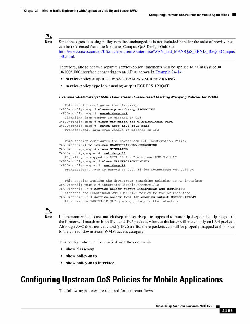
Chapter 24 Mobile Traffic Engineering with Application Visibility and Control (AVC)Configuring Upstream QoS Policies for Mobile Applications
Note Since the egress queuing policy remains unchanged, it is not included here for the sake of brevity, but can be referenced from the Medianet Campus QoS Design Guide at http://www.cisco.com/en/US/docs/solutions/Enterprise/WAN_and_MAN/QoS_SRND_40/QoSCampus_40.html.
Therefore, altogether two separate service-policy statements will be applied to a Catalyst 6500 10/100/1000 interface connecting to an AP, as shown in Example 24-14.
• service-policy output DOWNSTREAM-WMM-REMARKING
• service-policy type lan-queuing output EGRESS-1P3Q8T
Example 24-14 Catalyst 6500 Downstream Class-Based Marking Mapping Policies for WMM
! This section configures the class-mapsC6500(config-cmap)# class-map match-any SIGNALINGC6500(config-cmap)# match dscp cs3 ! Signaling from campus is matched on CS3C6500(config-cmap)# class-map match-all TRANSACTIONAL-DATAC6500(config-cmap)# match dscp af21 af22 af23 ! Transactional Data from campus is matched on AF2
! This section configures the Downstream DSCP-Restoration PolicyC6500(config)# policy-map DOWNSTREAM-WMM-REMARKINGC6500(config-pmap)# class SIGNALINGC6500(config-pmap-c)# set dscp 33 ! Signaling is mapped to DSCP 33 for Downstream WMM Gold ACC6500(config-pmap-c)# class TRANSACTIONAL-DATAC6500(config-pmap-c)# set dscp 35 ! Transactional-Data is mapped to DSCP 35 for Downstream WMM Gold AC
! This section applies the downstream remarking policies to AP interfaceC6500(config-pmap-c)# interface GigabitEthernet1/10C6500(config-if)# service-policy output DOWNSTREAM-WMM-REMARKING ! Attaches the DOWNSTREAM-WMM-REMARKING policy to the AP interfaceC6500(config-if)# service-policy type lan-queuing output EGRESS-1P7Q4T ! Attaches the EGRESS-1P3Q8T queuing policy to the interface
Note It is recommended to use match dscp and set dscp—as opposed to match ip dscp and set ip dscp—as the former will match on both IPv4 and IPv6 packets, whereas the latter will match only on IPv4 packets. Although AVC does not yet classify IPv6 traffic, these packets can still be properly mapped at this node to the correct downstream WMM access category.
This configuration can be verified with the commands:
• show class-map
• show policy-map
• show policy-map interface
Configuring Upstream QoS Policies for Mobile ApplicationsThe following policies are required for upstream flows:
24-55Cisco Bring Your Own Device (BYOD) CVD

Chapter 24 Mobile Traffic Engineering with Application Visibility and Control (AVC)Configuring Upstream QoS Policies for Mobile Applications
• Wireless Device Marking and WMM Policies—QoS policies are embedded within mobile application software and operating systems which can mark UP and DSCP values as well as assign application traffic into the respective WMM access categories in the radio-upstream direction. These policies are shown as point A in Figure 24-33.
• AP Access-Switch QoS Policies—These policies are typically applied on access switch ingress and are shown as point B in Figure 24-33.
• WLC AVC Profiles—Applied on WLC ingress and are shown as point C in Figure 24-15; when configured, these policies apply in both directions-therefore no additional configuration is required to configure AVC QoS in the upstream direction.
• WLC QoS Profiles—Applied on WLC egress and are shown as point D in Figure 24-15; when configured, these policies apply in both directions-therefore no additional configuration is required to configure QoS in the upstream direction.
Figure 24-33 Upstream QoS Policy Configuration Points in Wired/Wireless Networks
Each of these sets of policies will be covered in detail in the respective following sections.
Wireless Device Marking and WMM PoliciesThe initial upstream over-the-air WMM policies are up to the mobile application vendor to include within their application software and the network administrator has no control over these policies. However, they really only have effect in the upstream “first-hop” to the AP (whereas the majority of traffic to wireless devices flows in the downstream direction, which administrators can control via WLC AVC and QoS profiles).
Nonetheless, it is not a matter of every application on every BYOD device behaving in the same manner. Consider Figure 24-34, which shows various Cisco, Apple, and Samsung phones and their corresponding voice and signaling IP and DSCP marking values.
2941
99
AP
AP AccessSwitch
WLC WLCSwitch
Upstream
CAWAP Tunnels802.1Q TrunkA C D
B
24-56Cisco Bring Your Own Device (BYOD) CVD

Chapter 24 Mobile Traffic Engineering with Application Visibility and Control (AVC)Configuring Upstream QoS Policies for Mobile Applications
Figure 24-34 Mobile Wireless IP Phone/Smartphone 802.11 UP and DSCP Marking Values by
Hardware Vendor1
Additionally, 802.11 UP and DSCP markings are virtually non-existent on tablet devices, as shown by Figure 24-35.
Figure 24-35 Mobile Wireless Tablet 802.11 UP and DSCP Marking Values by Hardware Vendor2
And finally UP and DSCP markings for laptop applications are shown in Figure 24-36, which are similarly absent.
Figure 24-36 Mobile Laptop 802.11 UP and DSCP Marking Values by Hardware Vendor3
1. BYOD with QoS http://mrncciew.com/2013/01/08/byod-with-qos/
2. BYOD with QoS http://mrncciew.com/2013/01/08/byod-with-qos/
3. BYOD with QoS http://mrncciew.com/2013/01/08/byod-with-qos/
24-57Cisco Bring Your Own Device (BYOD) CVD

Chapter 24 Mobile Traffic Engineering with Application Visibility and Control (AVC)Configuring Upstream QoS Policies for Mobile Applications
Without WMM markings on these wireless client devices, these multimedia applications have reduced quality on their radio upstream connections.
AP Access Switch Upstream QoS PoliciesAs shown in the above tables, most applications do not yet mark media and signaling flows. However those that do typically mark signaling flows to UP 4 and DSCP CS3. This presents a slight misalignment in QoS policies, as UP 4 will be mapped to (an outer CAPWAP DSCP value of) AF31 (as shown in Figure 24-13) as it is received by the access point (refer to Table 24-4). As such, signaling traffic will not have the proper QoS applied to it in the upstream direction in transit over the wired network between the AP and the WLC. Only when it exits the WLC in the upstream direction is the original inner DSCP value (of CS3) going to be used.
Therefore, to correct this, administrators can configure an ingress marking policy on the access switch interface(s) connecting to wireless access points that receives traffic marked AF31 (which is derived by the AP mapping for UP 4) and remarking these to DSCP CS3. Such remarking policies will now be presented for the same access switches as before, specifically, the:
• Catalyst 3750
• Catalyst 4500
• Catalyst 6500
Catalyst 3750 Configuration Example
The upstream ingress configuration required on a Catalyst 3750 switch to remap Signaling traffic from (the AP UP 4 mapped marking of) AF31 to the enterprise marking of CS3 is shown in Example 24-15.
Example 24-15 Catalyst 3750 Upstream Signaling-Marking Restoration
! This section configures the class-mapC3750-X(config-cmap)# class-map match-all AP-SIGNALINGC3750-X(config-cmap)# match ip dscp af31 ! Signaling traffic from the AP is matched on DSCP AF31
! This section configures the Network Upstream Remarking policy-mapC3750-X(config-cmap)# policy-map UPSTREAM-WMM-REMARKINGC3750-X(config-pmap-c)# class AP-SIGNALINGC3750-X(config-pmap-c)# set dscp cs3 ! Signaling is remarked to DSCP 24 to align to enterprise QoS model
! This section attaches the upstream policy to the AP-connected interfaceC3750-X(config)# interface GigabitEthernet1/0/10C3750-X(config-if)# mls qos trust dscp ! Configures the port to statically trust DSCP on ingressC3750-X(config-if)# service-policy input UPSTREAM-WMM-REMARKING ! Attaches the upstream DSCP remarking policy to the AP interface on ingress
This configuration can be verified with the commands:
• show mls qos interface
• show class-map
• show policy-map
• show policy-map interface
24-58Cisco Bring Your Own Device (BYOD) CVD

Chapter 24 Mobile Traffic Engineering with Application Visibility and Control (AVC)Configuring Upstream QoS Policies for Mobile Applications
Catalyst 4500 Configuration Example
The upstream ingress configuration required on a Catalyst 4500 switch to remap Signaling traffic from (the AP UP 4 mapped marking of) AF31 to the enterprise marking of CS3 is shown in Example 24-16.
Example 24-16 Catalyst 4500 Upstream Signaling-Marking Restoration
! This section configures the class-mapC4500(config-cmap)# class-map match-all AP-SIGNALINGC4500(config-cmap)# match dscp af31 ! Signaling traffic from the AP is matched on DSCP AF31
! This section configures the Network Downstream Remarking policy-mapC4500(config-cmap)# policy-map UPSTREAM-MAPPINGC4500(config-pmap-c)# class AP-SIGNALINGC4500(config-pmap-c)# set dscp cs3 ! Signaling is remarked to DSCP 24 to align to enterprise QoS model
! This section attaches the upstream and downstream policies to AP interfaceC4500(config)# interface GigabitEthernet 3/1C4500(config-if)# service-policy input UPSTREAM-MAPPING ! Attaches the upstream DSCP remarking policy to the AP interface on ingressC4500(config-if)# service-policy output 1P7Q1T+DBL+DOWNSTREAM-MAPPING ! Attaches the combined egress queuing and remarking policy to the AP interface
This configuration can be verified with the commands:
• show class-map
• show policy-map
• show policy-map interface
Catalyst 6500 Configuration Example
The upstream ingress configuration required on a Catalyst 6500 switch to remap Signaling traffic from (the AP UP 4 mapped marking of) AF31 to the enterprise marking of CS3 is shown in Example 24-17.
Example 24-17 Catalyst 6500 Upstream Signaling-Marking Restoration
! This section configures the class-mapC6500(config-cmap)# class-map match-all AP-SIGNALINGC6500(config-cmap)# match dscp af31 ! Signaling traffic from the AP is matched on DSCP AF31
! This section configures the Network Downstream Remarking policy-mapC6500(config-cmap)# policy-map UPSTREAM-WMM-REMARKINGC6500(config-pmap-c)# class AP-SIGNALINGC6500(config-pmap-c)# set dscp cs3 ! Signaling is remarked to DSCP 24 to align to enterprise QoS model
! This section applies the upstream & downstream remarking policies to AP interfaceC6500(config-pmap-c)# interface GigabitEthernet1/10C6500(config-if)# service-policy input UPSTREAM-WMM-REMARKING ! Attaches the UPSTREAM-WMM-REMARKING policy to the AP interface on ingressC6500(config-if)# service-policy output DOWNSTREAM-WMM-REMARKING ! Attaches the DOWNSTREAM-WMM-REMARKING policy to the AP interface on egressC6500(config-if)# service-policy type lan-queuing output EGRESS-1P7Q4T
24-59Cisco Bring Your Own Device (BYOD) CVD

Chapter 24 Mobile Traffic Engineering with Application Visibility and Control (AVC)Application Visibility and Management
! Attaches the EGRESS-1P3Q8T queuing policy to the interface on egress
This configuration can be verified with the commands:
• show class-map
• show policy-map
• show policy-map interface
Application Visibility and ManagementThe Cisco AVC feature can be used for application monitoring and management on:
• Centralized Wireless LAN controllers
• Converged access platforms
Each of these platforms is presented in turn.
Centralized WLC Application Visibility and ManagementCisco AVC for wireless LAN controllers provides application visibility:
• Globally
• On an WLAN basis
• On an individual client basis
Additionally, AVC supports the export of application statistics via Netflow.
Each of these options is presented in turn.
Note It should be noted that in order to see any application visibility statistics on either a global, WLAN, or client level, the Application Visibility feature must be enabled on at least one WLAN, as shown in Figure 24-17.
Global Application VisibilityTo see application traffic at a global level for all traffic traversing the WLC, click the MONITOR heading bar and from the main Summary screen (in the bottom right corner) the Top 10 applications are summarized by name, as well as by Packet and Byte Count, as shown in Figure 24-37.
24-60Cisco Bring Your Own Device (BYOD) CVD

Chapter 24 Mobile Traffic Engineering with Application Visibility and Control (AVC)Application Visibility and Management
Figure 24-37 Global Application Visibility Monitoring
This information can also be collected via CLI by issuing the command:
• show avc statistics top-apps { upstream | downstream}
Per-WLAN Application VisibilityTo see application traffic at a WLAN-level, perform the following steps.
1. Click the Monitor heading bar.
2. Select the Applications link on the lower-left.
3. Select the WLAN ID to be monitored.
Application traffic for the WLAN is summarized in the following tabs:
• Aggregate—Includes both upstream and downstream application traffic.
• Upstream—Upstream-only application traffic.
• Downstream—Downstream-only application traffic.
Per-WLAN application visibility monitoring is shown in Figure 24-38.
24-61Cisco Bring Your Own Device (BYOD) CVD

Chapter 24 Mobile Traffic Engineering with Application Visibility and Control (AVC)Application Visibility and Management
Figure 24-38 Per-WLAN Application Visibility Monitoring
This information can also be collected via CLI by issuing the commands:
• show avc statistics wlan [WLAN_Number] top-apps { upstream | downstream}
• show avc statistics wlan [WLAN_Number] top-app-groups { upstream | downstream}
• show avc statistics wlan [WLAN_Number] application [application_name]
Per-Client Application VisibilityTo see application traffic at a client-level, perform the following steps.
1. Click the Monitor heading bar.
2. Select the Clients link on the left.
3. Select the Client MAC Addr of the client to be monitored.
Per-Client application visibility monitoring is shown in Figure 24-39.
24-62Cisco Bring Your Own Device (BYOD) CVD

Chapter 24 Mobile Traffic Engineering with Application Visibility and Control (AVC)Application Visibility and Management
Figure 24-39 Per-Client Application Visibility Monitoring
This information can also be collected via CLI by issuing the commands:
• show avc statistics client [client_mac]
• show avc statistics client [client_mac] application [application_name]
NetFlow ExportNetFlow is a protocol that provides information about network users and applications, peak usage times, and traffic routing. The NetFlow protocol collects IP traffic information from network devices to monitor traffic. The NetFlow architecture consists of the following components:
• Collector—Entity that collects all the IP traffic information from various network elements.
• Exporter—Network entity that exports the template with the IP traffic information. The WLC can be configured to act as an exporter.
NetFlow Export Configuration-GUI
Netflow Export can be configured on the WLC via the GUI by performing the following steps:
1. Click the Wireless heading bar and expand the Netflow link and click Exporter.
2. Click New.
3. Enter the Exporter name, IP address, and the port number.
4. Click Apply.
5. Click Save Configuration.
24-63Cisco Bring Your Own Device (BYOD) CVD

Chapter 24 Mobile Traffic Engineering with Application Visibility and Control (AVC)Application Visibility and Management
NetFlow Monitoring can be configured by following these steps:
1. Click the Wireless heading bar and expand the Netflow link and click Monitor.
2. Click New and enter the Monitor name.
3. On the Monitor List page, click the Monitor name to open the Netflow Monitor > Edit page.
4. Choose the Exporter name and the Record name from the respective drop-down lists.
5. Click Apply.
6. Click Save Configuration.
A NetFlow Monitor can be associated with a WLAN by following these steps:
1. Click the WLANs heading bar and click the WLAN ID to open the WLANs > Edit page.
2. In the QoS tab, choose the NetFlow Monitor from the Netflow Monitor drop-down list.
3. Click Apply.
4. Click Save Configuration.
NetFlow Export Configuration-CLI
Create an Exporter by entering this command:
config flow create exporter exporter-name ip-addr port-number
Create a NetFlow Monitor by entering this command:
config flow create monitor monitor-name
Associate a NetFlow Monitor with an Exporter by entering this command:
config flow add monitor monitor-name exporter exporter-name
Associate a NetFlow Monitor with a Record by entering this command:
config flow add monitor monitor-name record ipv4_client_app_flow_record
Associate a NetFlow Monitor with a WLAN by entering this command:
config wlan flow wlan-id monitor monitor-name enable
NetFlow configurations can be verified with the following show commands:
• show flow monitor summary
• show flow exporter {summary | statistics}
Converged Access Application VisibilityOn the Converged Access platforms, such as the Cisco WLC5760 and Catalyst 3850, the Application Visibility and Control feature (in its initial release) can only be used for application visibility monitoring and currently cannot be used to set QoS policies to “control” network traffic. Therefore this feature might be more accurately expressed as a truncated acronym “AV” for “Application Visibility”; however for the sake of consistency we will continue to refer to it as AVC.
24-64Cisco Bring Your Own Device (BYOD) CVD

Chapter 24 Mobile Traffic Engineering with Application Visibility and Control (AVC)Application Visibility and Management
Note System testing manifested an incompatibility of the AVC feature in conjunction with the TrustSec feature on the Cisco 5760 wireless LAN controller in Cisco IOS XE Release 3.3SE. However this issue has been resolved and successfully tested and will be included in the next major software release.
Nonetheless, AVC has important use cases in capacity planning and network usage baselining over converged access networks. For example, if network administrators are provided visibility into the top bandwidth-consuming applications and/or are able to trend application-usage, then they can better plan for network infrastructure upgrades. Additionally, armed with such information, they can elect control application traffic over the Cisco wired network in the downstream direction (which typically represents the majority of WLAN traffic anyway).
The AVC feature on converged access platforms performs deep packet inspection via the NBAR2 engine to identify a wide array of applications on either a per-WLAN basis or on a per-client basis. This would include the ability to:
• Identify the Top Applications on each WLAN (in terms of byte counts and packet counts)
• Identify the Top Users on each WLAN (in terms of byte counts and packet counts)
• Identify the Top Details on each WLAN (to cross-reference Top Application and Top User traffic details)
– For example, break down Top Applications within a given WLAN on a per-user basis, complete with byte count and packet count statistics.
Such Top-n reports can be generated on a Per-WLAN basis or a Per-Client basis, as will be shown. Additionally, such information is available via CLI as well as via the web GUI.
Such statistics can answer questions like:
• Which users are contributing to the Top Application usage?
• What applications are the Top Users using?
Converged Access AVC Configuration via CLI
The steps to configure AVC on converged access platforms via CLI are:
To configure AVC, follow these general steps:
1. Create a flow record.
2. (Optional) Create a flow exporter.
3. Create a flow monitor.
4. Apply the flow monitor to a WLAN.
Each of these steps is detailed in turn.
Configure a Flow Record
The first step in configuring AVC for converged access platforms is to configure a flow record. A flow record specifies the details of a given flow that is to be tracked by matching one or more of the following parameters:
• (IPv4) Source Address
• (IPv4) Destination Address
• Transport Protocol Source-Port
24-65Cisco Bring Your Own Device (BYOD) CVD

Chapter 24 Mobile Traffic Engineering with Application Visibility and Control (AVC)Application Visibility and Management
• Transport Protocol Destination Port
• Flow Direction
• Application Name
• WLAN SSID
Note AVC on the converged access platforms only supports IPv4 protocols.
Once the match details are specified so as to identify a discrete flow, then the flow record also specifies the type of statistics and information that is to collected by the flow record, including:
• Bytes
• Packets
• Access Point (BSSID) MAC address
• Client MAC address
The syntax to configure a flow record on a converged access platform is shown in Example 24-18.
Example 24-18 Configuring a Flow Record via CLI
C3850(config)# flow record AVC-FLOW-RECORD ! defines a flow record with name "AVC-FLOW-RECORD"C3850(config-flow-record)# match ipv4 protocol ! Matches IPv4 protocolC3850(config-flow-record)# match ipv4 source address ! Matches flows by IPv4 source addressesC3850(config-flow-record)# match ipv4 destination address ! Matches flows by IPv4 destination addessesC3850(config-flow-record)# match transport source-port ! Matches flows by TCP/UDP source portC3850(config-flow-record)# match transport destination-port ! Matches flows by TCP/UDP destination portC3850(config-flow-record)# match flow direction ! Matches flows by directionC3850(config-flow-record)# match application name ! Matches flows by AVC application namesC3850(config-flow-record)# match wireless ssid ! Matches flows by WLAN SSIDs
! This section details the statistics and information to be collected ! by the flow recordC3850(config-flow-record)# collect counter bytes long ! Enables a 64-bit counter for all bytes belonging to the flowC3850(config-flow-record)# collect counter packets long ! Enables a 64-bit counter for all packets belonging to the flowC3850(config-flow-record)# collect wireless ap mac address ! Captures the MAC of the AP C3850(config-flow-record)# collect client mac address ! Captures the MAC of the client
Configure a Flow Exporter
An optional second step is to configure a flow exporter. The flow exporter defines the destination and transport parameters of the management station that the flow details are to be exported to via Flexible NetFlow (FNF). Application flow information is gathered by the NBAR2 engine on the access point and sent to the management station using NetFlow version 9 format.
24-66Cisco Bring Your Own Device (BYOD) CVD

Chapter 24 Mobile Traffic Engineering with Application Visibility and Control (AVC)Application Visibility and Management
The configuration of a flow exporter is shown in Example 24-19.
Example 24-19 Configuring a Flow Exporter via CLI
C3850(config)# flow exporter AVC-FLOW-EXPORTER ! Defines a flow exporter with name "AVC-FLOW-EXPORTER"C3850(config-flow-exporter)# destination {hostname | ip-address} ! Specifies the hostname or destination IP address of the collectorC3850(config-flow-exporter)# transport udp port-value ! Specifies the UDP port C3850(config-flow-exporter)# option application-table timeout seconds ! Optional: specifies the timeout value of the application tableC3850(config-flow-exporter)# option usermac-table timeout seconds ! Optional: specifies the timeout value of the client mac table
The configuration of a flow exporter can be verified with the show flow exporter verification command, as displayed in Example 24-20.
Example 24-20 Verifying a Flow Exporter—show flow exporter verification command
C3850# show flow exporterFlow Exporter AVC-FLOW-EXPORTER: Description: User defined Export protocol: NetFlow Version 9 Transport Configuration: Destination IP address: 10.0.1.99 Source IP address: 10.225.102.197 Transport Protocol: UDP Destination Port: 100 Source Port: 65353 DSCP: 0x0 TTL: 255 Output Features: Used Options Configuration: usermac-table (timeout 1000 seconds) application-table (timeout 1000 seconds)
C3850#
Configure a Flow Monitor
The next step in configuring AVC on a converged access platform is to configure a flow monitor. A flow monitor associates a flow record with an optional flow exporter and can be applied to a WLAN. The configuration of a flow monitor is shown in Example 24-21.
Example 24-21 Configuring a Flow Monitor via CLI
C3850(config)# flow monitor AVC-FLOW-MONITOR ! Configures a flow monitor with name "AVC-FLOW-MONITOR"C3850(config-flow-monitor)# record AVC-FLOW-RECORD ! Associates the flow monitor with the "AVC-FLOW-RECORD" flow recordC3850(config-flow-monitor)# exporter AVC-FLOW-EXPORTER ! Associates the flow monitor with the "AVC-FLOW-EXPORTER" flow exporterC3850(config-flow-monitor)# cache timeout active seconds ! Optional: specifies the active cache timeout in secondsC3850(config-flow-monitor)# cache timeout inactive seconds ! Optional: specifies the inactive cache timeout in seconds ! Cisco recommends the inactive cache timeout to be greater than 90 seconds
24-67Cisco Bring Your Own Device (BYOD) CVD

Chapter 24 Mobile Traffic Engineering with Application Visibility and Control (AVC)Application Visibility and Management
Apply the Flow Monitor to a WLAN
Once the flow monitor has been defined, then it can be applied to a given WLAN(s) and the direction of application can be specified, as shown in Example 24-22.
Example 24-22 Applying a Flow Monitor to a WLAN via CLI
C3850(config)# wlan BYOD-EMPLOYEEC3850(config-wlan)# ip flow monitor AVC-FLOW-MONITOR input ! Applies the "AVC-FLOW-MONITOR" to the WLAN in the input directionC3850(config-wlan)# ip flow monitor AVC-FLOW-MONITOR output ! Applies the "AVC-FLOW-MONITOR" to the WLAN in the output direction
The application of a flow monitor to a WLAN can be verified with the show wlan verification command, as illustrated in Example 24-23.
Example 24-23 Verifying a WLAN—show wlan id verification command
WLC5760# show wlan id 1WLAN Profile Name : BYOD_Employee================================================Identifier : 1Network Name (SSID) : BYOD_EmployeeStatus : EnabledBroadcast SSID : Enabled
<output truncated>
AVC Visibility : EnabledNetflow Monitor : AVC-FLOW-MONITOR Direction : Input Traffic : IPv4Netflow Monitor : AVC-FLOW-MONITOR Direction : Output Traffic : IPv4
Converged Access AVC Configuration via GUI
Converged access platforms can also be configured via the web GUI. Specifically, the wireless features of these platforms can be configured via GUI by pointing a browser to http://{hostname_or_IP_Address}/wireless.
Additionally, to facilitate operation, a default flow record (named wireless avc basic) and a default flow monitor (named wireless-avc-basic) are preconfigured.
Note If you are using a user-defined flow record and flow monitor, then the record name and monitor name should be same. This is specific only for configuring AVC via the GUI (and does not apply for AVC CLI configuration). You can use the flow monitor you have created either for upstream or downstream, or both, but ensure that you use the same record name while mapping with the flow monitor.
The steps for configuring AVC via the GUI are detailed below:
Step 1 Choose Configuration > Wireless > WLAN.
The WLAN page appears, as shown in Figure 24-40.
24-68Cisco Bring Your Own Device (BYOD) CVD

Chapter 24 Mobile Traffic Engineering with Application Visibility and Control (AVC)Application Visibility and Management
Figure 24-40 WLAN Configuration Page
Step 2 Click on corresponding WLAN ID to open WLAN Edit page and click AVC.
The Application Visibility page appears.
a. Select the Application Visibility Enabled check box to enable AVC on a WLAN.
b. In the Upstream Profile text box, enter the name of the AVC profile.
c. In the Downstream Profile text box, enter the name of the AVC profile.
These options are shown in Figure 24-41, where the default flow monitor name (wireless-avc-basic) is used in both directions.
Figure 24-41 Per-WLAN AVC Configuration Page
To enable AVC, you need to enter the profile names for the upstream and downstream profiles. The profile names are the flow monitor names. By default, the flow monitor names (wireless-avc-basic) appear in the Upstream Profile and Downstream Profile text boxes.
You can change the profile names for the upstream and downstream profiles, but ensure that the same flow records are available for the flow monitors. Additionally, the upstream and downstream profiles can have different profile names.
Step 3 Click Apply to apply AVC on the WLAN.
24-69Cisco Bring Your Own Device (BYOD) CVD

Chapter 24 Mobile Traffic Engineering with Application Visibility and Control (AVC)Application Visibility and Management
Converged Access AVC Monitoring via CLI
Once the flow records, (optional exporters) and monitors have been configured and applied to a WLAN(s), then these can be used to provide application visibility on either a:
• Per-Access-Point basis
• Per-WLAN basis
• Per-client basis
Each of these options is discussed in turn.
CLI-Based Per-Access Point Application Visibility Monitoring
In converged access platform CLI, the command to display application visibility on a per-Access Point basis is the show avc nbar statistics command, as presented in Example 24-24.
Example 24-24 CLI-Based Per-AP AVC Monitoring Examples—show avc nbar statistics Verification
Command
ROD.BB01.e10c# show avc nbar statistics
Dumping NBAR2 Statistics :
ID Protocol Name IN OUT === ============= == === 0 none 14374 0 1 unknown 57905 34933 3 http 42202 72505 6 icmp 113 35 13 dhcp 789 535 16 secure-http 477 1111 31 ntp 244 6 48 tftp 110 21 65 sip 254 257 66 rtcp 31 0 72 dns 5089 4274 82 youtube 1247 1558 83 skype 678 800 120 audio-over-http 30369 83941 122 video-over-http 95751 329352 461 itunes 155529 342414 1073 gmail 3220 4635 1083 yahoo-accounts 33 39 1306 webex-meeting 872 704 1312 ssl 23886 27554 1316 netflix 11 9 1404 ping 665 625 1421 netbios-ns 35 0 1434 ms-live-accounts 24 28 1440 google-accounts 251 209 1444 salesforce 2254 2124 1445 windows-azure 1627 4495 1446 hotmail 489 337 1453 twitter 5 5 1454 facebook 414 414 1456 google-services 18010 20442 1462 yahoo-mail 6840 5655 1469 facetime 60 42 ================================
24-70Cisco Bring Your Own Device (BYOD) CVD

Chapter 24 Mobile Traffic Engineering with Application Visibility and Control (AVC)Application Visibility and Management
CLI-Based Per-WLAN Application Visibility Monitoring
In converged access platform CLI, the command to display application visibility on a per-WLAN basis is the show avc wlan command, which can take the following parameters:
show avc wlan <wlan-id> top <number> application [aggregate | downstream |upstream]
Displays the Top-N Applications by WLAN, where:
• wlan-id represents the name of the WLAN.
• number (1-30) is the number of Top-N Applications to be displayed.
• aggregate displays the upstream and downstream aggregate stats for Top-N applications.
• downstream displays the downstream stats (only) for Top-N applications.
• upstream displays the upstream stats (only) for Top-N applications.
Example 24-25 CLI-Based Per-WLAN AVC Monitoring Examples—show wlan id Verification Command
CT5760# show avc wlan BYOD_Employee top 10 app aggregateCumulative Stats:
No. AppName Packet-Count Byte-Count AvgPkt-Size usage%------------------------------------------------------------------------------------------------------1 itunes 278859 254127765 911 392 video-over-http 218949 252675674 1154 383 http 52734 41694075 790 64 ssl 48555 26677396 549 45 audio-over-http 44896 47851856 1065 76 google-services 25924 21600740 833 37 unknown 14201 1114028 78 08 yahoo-mail 12495 11850149 948 29 gmail 5530 4473175 808 110 salesforce 4248 1826766 430 0
Last Interval(90 seconds) Stats:
No. AppName Packet-Count Byte-Count AvgPkt-Size usage%------------------------------------------------------------------------------------------------------1 yahoo-mail 3394 3247526 956 872 skype 363 295879 815 83 gmail 183 56892 310 24 unknown 173 16114 93 05 http 126 82495 654 26 ssl 106 29181 275 17 dns 38 4717 124 08 salesforce 16 11923 745 09 hotmail 12 4911 409 010 dhcp 6 1968 328 0
CLI-Based Per-Client Application Visibility Monitoring
In converged access platform CLI, the command to display application visibility on a per-client basis is the show avc client command, which can take the following parameters:
show avc client <client_MAC> top <number> application [aggregate | downstream |upstream]
Displays the Top-N Applications by Client, where:
• client_MAC is the client’s MAC address in 0.0.0 format.
• number (1-30) is the number of Top-N Applications to be displayed.
• aggregate displays the upstream and downstream aggregate stats for Top-N applications.
• downstream displays the downstream stats (only) for Top-N applications.
24-71Cisco Bring Your Own Device (BYOD) CVD

Chapter 24 Mobile Traffic Engineering with Application Visibility and Control (AVC)Application Visibility and Management
• upstream displays the upstream stats (only) for Top-N applications.
Example 24-26 CLI-Based Per-Client AVC Monitoring Examples—show avc client Verification Command
CT5760# show avc client b4f0.abd0.28a6 top 10 app aggregateCumulative Stats:
No. AppName Packet-Count Byte-Count AvgPkt-Size usage%------------------------------------------------------------------------------------------------------1 audio-over-http 51527 55441417 1075 912 http 4620 3387144 733 53 ssl 4171 2754485 660 44 unknown 1534 168533 109 05 webex-meeting 311 68094 218 06 dns 303 36848 121 07 google-services 206 66414 322 08 youtube 167 107982 646 09 sip 96 36152 376 010 google-accounts 50 29192 583 0
Last Interval(90 seconds) Stats:
No. AppName Packet-Count Byte-Count AvgPkt-Size usage%------------------------------------------------------------------------------------------------------1 ssl 498 325997 654 442 http 327 278764 852 373 youtube 167 107982 646 144 unknown 108 7571 70 15 google-accounts 50 29192 583 46 dns 22 2656 120 07 audio-over-http 5 260 52 0
Converged Access AVC Monitoring via GUI
You can view AVC information on a WLAN in a single shot via the pie chart on the Home page of the converged access platform, as shown in Figure 24-42. The pie chart displays the AVC data (Aggregate - Application Cumulative usage %) of the first WLAN. Also, the top five WLANs (based on number of clients) are also listed and can be clicked to view their corresponding pie chart information.
Note If AVC is not enabled on the first WLAN, then the Home page does not display the AVC pie chart.
24-72Cisco Bring Your Own Device (BYOD) CVD
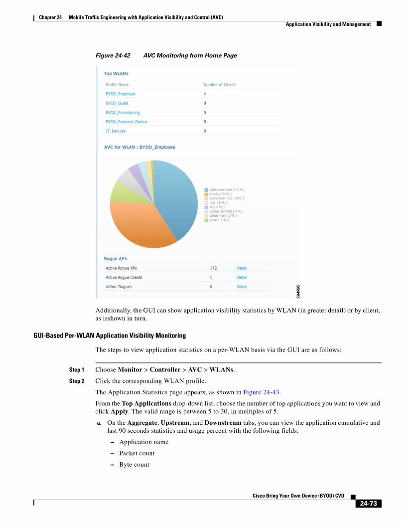
Chapter 24 Mobile Traffic Engineering with Application Visibility and Control (AVC)Application Visibility and Management
Figure 24-42 AVC Monitoring from Home Page
Additionally, the GUI can show application visibility statistics by WLAN (in greater detail) or by client, as isshown in turn.
GUI-Based Per-WLAN Application Visibility Monitoring
The steps to view application statistics on a per-WLAN basis via the GUI are as follows:
Step 1 Choose Monitor > Controller > AVC > WLANs.
Step 2 Click the corresponding WLAN profile.
The Application Statistics page appears, as shown in Figure 24-43.
From the Top Applications drop-down list, choose the number of top applications you want to view and click Apply. The valid range is between 5 to 30, in multiples of 5.
a. On the Aggregate, Upstream, and Downstream tabs, you can view the application cumulative and last 90 seconds statistics and usage percent with the following fields:
– Application name
– Packet count
– Byte count
24-73Cisco Bring Your Own Device (BYOD) CVD

Chapter 24 Mobile Traffic Engineering with Application Visibility and Control (AVC)Application Visibility and Management
– Average packet size
– usage (%)
Figure 24-43 Per-WLAN AVC Monitoring GUI
GUI-Based Per-Client Application Visibility Monitoring
The steps to view application statistics on a per-client basis via the GUI are as follows:
Step 1 Choose Monitor > Clients > Client Details > Clients.
Step 2 Click Client MAC Address and then click the AVC Statistics tab.
The Application Visibility page appears, as shown in Figure 24-44.
a. On the Aggregate, Upstream, and Downstream tabs, you can view the application cumulative and last 90 seconds statistics and usage percent with the following fields:
– Application name
– Packet count
– Byte count
– Average packet size
– usage (%)
24-74Cisco Bring Your Own Device (BYOD) CVD

Chapter 24 Mobile Traffic Engineering with Application Visibility and Control (AVC)Summary
Figure 24-44 Per-Client AVC Monitoring GUI
SummaryThis design document presented the business case for managing applications over wireless networks, highlighting the macro trends in wireless traffic volume growth and application trends. Benefits of applying policies to manage application quality were presented, including increasing voice and video quality, business-critical application responsiveness, as well as controlling background applications and non-business applications over wireless networks.
Next, to set design context, wireless QoS tools were overviewed to show how these evolved and operate, highlighting both their capabilities as well as their limitations. Following this, a discussion of how Layer 2 and Layer 3 mapping works over Cisco wired and wireless networks was presented, including a QoS Translation Table that performs non-default mappings to reconcile IEEE Layer 2 markings with IETF Layer 3 markings in Cisco WLCs and APs.
Subsequently, the various policies required to ensure QoS in both the downstream and upstream directions were summarized, including:
• QoS Profiles
• AVC Profiles
• Network switch DSCP-mapping
• Mobile Device WMM marking
Each of these main policy elements were then discussed in detail to show how these could be configured. WLC policies configuration—namely QoS and AVC Profiles—were presented both in GUI format and in CLI commands.
24-75Cisco Bring Your Own Device (BYOD) CVD

Chapter 24 Mobile Traffic Engineering with Application Visibility and Control (AVC)Additional Reading
Wired network switch policies for the access switches connecting to Cisco wireless access points were presented for a Four-Class, Eight-Class, and Twelve-Class enterprise strategic application-class models mapped to WMM. Additionally, these policies configurations were shown for Catalyst 3750, 4500, and 6500 series switches, highlighting the platform-specific idiosyncrasies in function and CLI relating to the policy configurations.
Also, administrators were shown how to monitor application visibility on a global level, WLAN level, and a client level, as well as how to configure NetFlow Export and Monitoring for network management purposes.
And finally, corresponding CLI-based and GUI-based commands for configuring and monitoring AVC on converged access platforms were presented.
Additional Reading• Cisco Wireless LAN Controller Configuration Guide, Release 7.6
http://www.cisco.com/en/US/docs/wireless/controller/7.6/configuration/guide/b_cg76.html
– Configuring QoShttp://www.cisco.com/en/US/docs/wireless/controller/7.6/configuration/guide/b_cg76_config_qos.html
– Configuring Application Visibility and Controlhttp://www.cisco.com/en/US/docs/wireless/controller/7.6/configuration/guide/b_cg76_chapter_01111.html
– Working With WLANS-Assigning QoS Profileshttp://www.cisco.com/en/US/docs/wireless/controller/7.6/configuration/guide/b_cg76_chapter_01010011.html
• Consolidated Platform Configuration Guide, Cisco IOS XE 3.3SE (Catalyst 3850 Switches)-Configuring Application Visibility and Control http://www.cisco.com/en/US/docs/switches/lan/catalyst3850/software/release/3se/consolidated_guide/configuration_guide/b_consolidated_3850_3se_cg_chapter_01110111.html
• Medianet QoS 4.0 Design:
– Strategic QoS Design Overview 4.0http://www.cisco.com/en/US/docs/solutions/Enterprise/WAN_and_MAN/QoS_SRND_40/QoSIntro_40.html
– Campus QoS Design 4.0http://www.cisco.com/en/US/docs/solutions/Enterprise/WAN_and_MAN/QoS_SRND_40/QoSCampus_40.html#wp1099462
24-76Cisco Bring Your Own Device (BYOD) CVD