
MOBILE OFFSHORE UNITS - Rules and standards 6... · B 300 Blowout preventer control. .~ ... C 300...
30
RULES FOR CLASSIFICATION OF MOBILE OFFSHORE UNITS SPECIAL EQUIPMENT AND SYSTEMS ADDITIONAL CLASS PART 6 CHAPTER 5 DRILLING PLANT (DRILL) JANUARY 1993 SECTIONS PAGE 1 General ........................................................................................................... 1 2 Materials . . . . . . . . . . . . . . . . . . . . . . . . . . . . . . . . . . . . . . . . . . . . . . . . . . . . . . . . . . . . . . . . . . . . . . . . . . . . . . . . . . . . . . . . . . . . . . . . . . . . . . . . . 6 3 Design Principles . . . . . . . . . . . . . . . . . . . . . . . . . . . . . . . . . . . . . . . . . . . . . . . . . . . . . . . . . . . . . . . . . . . . . . . . . . . . . . . . . . . . . . . . . . . . . . . 8 4 Systems . . . . . . . . . . . . . . . . . . . . . . . . . . . . . . . . . . . . . . . . . . . . . . . . . . . . . . . . . . . . . . . . . . . . . . . . . . . . . . . . . . . . . . . . . . . . . . . . . . . . . . . . . . 10 5 Structural and Mechanical Components . . . . . . . . . . . . . . . . . . . . . . . . . . . . . . . . . . . . . . . . . . . . . . . . . . . . . . . . . . . . . . . . . . 13 6 Piping ....................................................................................... , .................... 15 7 Manufacture, Workmanship and Testing ................................................................. 17 APPENDICES A Supplementary Requirements of the Norwegian Petroleum Directorate (NPD) and the Norwegian Maritime Directorate (NMD) ............................................................... 20 B Supplementary Requirements of the U .K. Health and Safety Executive (HSE) . .. . . . . . . . . . . . . . . 26 DET NORSKE VERITAS CLASSIFICATION AS Veritasveien I, N-1322 Hevil<, Norway Tel.: +47 67 57 99 00 Fax: +47 67 57 99 11
Transcript of MOBILE OFFSHORE UNITS - Rules and standards 6... · B 300 Blowout preventer control. .~ ... C 300...

RULES FOR CLASSIFICATION OF
MOBILE OFFSHORE UNITS
SPECIAL EQUIPMENT AND SYSTEMS ADDITIONAL CLASS
PART 6 CHAPTER 5
DRILLING PLANT (DRILL) JANUARY 1993
SECTIONS PAGE
1 General ........................................................................................................... 1 2 Materials . . . . . . . . . . . . . . . . . . . . . . . . . . . . . . . . . . . . . . . . . . . . . . . . . . . . . . . . . . . . . . . . . . . . . . . . . . . . . . . . . . . . . . . . . . . . . . . . . . . . . . . . . 6 3 Design Principles . . . . . . . . . . . . . . . . . . . . . . . . . . . . . . . . . . . . . . . . . . . . . . . . . . . . . . . . . . . . . . . . . . . . . . . . . . . . . . . . . . . . . . . . . . . . . . . 8 4 Systems . . . . . . . . . . . . . . . . . . . . . . . . . . . . . . . . . . . . . . . . . . . . . . . . . . . . . . . . . . . . . . . . . . . . . . . . . . . . . . . . . . . . . . . . . . . . . . . . . . . . . . . . . . 10 5 Structural and Mechanical Components . . . . . . . . . . . . . . . . . . . . . . . . . . . . . . . . . . . . . . . . . . . . . . . . . . . . . . . . . . . . . . . . . . 13 6 Piping ....................................................................................... , .................... 15 7 Manufacture, Workmanship and Testing ................................................................. 17
APPENDICES
A Supplementary Requirements of the Norwegian Petroleum Directorate (NPD) and the Norwegian Maritime Directorate (NMD) ............................................................... 20
B Supplementary Requirements of the U .K. Health and Safety Executive (HSE) . .. . . . . . . . . . . . . . . 26
DET NORSKE VERITAS CLASSIFICATION AS Veritasveien I, N-1322 Hevil<, Norway Tel.: +47 67 57 99 00 Fax: +47 67 57 99 11

CHANGES IN THE RULES
General.
The present edition of the Rules includes additions and amendments decided by the Board as of December 1992, and supersedes the July 1988 edition of the same chapter. ·
The Rule changes come into force on 1st of July 1993.
This chapter is valid until superseded by a revised chapter. Supplements will not be issued except for an updated list of corrections presented in the introduction booklet. The introduction booklet is normally revised in January and July each year.
Revised chapters will be forwarded to all subscribers to the Rules. Buyers of reprints are advised to check the updated list of Rule chapters printed on the front page of the introduction booklet to ensure that the chapter is current.
© Det Norske Veritas
Main changes.
• Appendix A. Supplementary Requirements of the Norwegian Petroleum Directorate (NPD) and the Norwegian Maritime Directorate (NMD).
The whole appendix has been updated in accordance with the February 1992 revision of the NPD regulations.
• Appendix B. Supplementary Requirements of the U.K. Health and Safety Executive (HSE).
The appendix recognises change in U .K. offshore regulation \Vhereby HSE replaces DEn as responsible body and the 4th edition of Guidance Notes is referenced rather than the 3rd edition.
Corrections and Clarifications.
In addition to the above stated rule amendments, some detected errors have been corrected, and some clarifications have been made in the existing rule wording.
Computer Typesetting by Division Ship and Offshore, Det Norske Veritas Classification AS Printed in Norway by Det Norske Veritas January 1993
1.93.2000
It is agreed that save es provided below Det Norske Veritea, its subsidiaries, bodies, officers, directors, employees end agents shell have no liability for any loss, damage or expense allegedly caused directly or indirectly by their mistake or negligence, breech of warranty, or any other act, omission or errOf by them, including gross negligence or wilful misconduct by any such person with the exception of gross negligence or wilful misconduct b~ the governing bodies or senior executive officers of Det Norske Veritas. Thia applies regerdles.s of
~Yh~~~ ~eh~Wi;;f 1>ae~~g:rs°i[ee~~i~:;. h~ ~~~~~:r.a~y~~; ;~~ho~:~~! ~~~~ees ~1t~:r~~r:k~0~~~i~~:ro~ i\~r~ug:i~eri'e'!° o~ar~l~;!e~n°~~~i~~c~~i~~c;!d~s ;'~~fo~~~~f~~mai~i:~ g~v: on behalf of them end in consequence suffers a lose, damage or expense proved to be due to their negligence, omiasion or default, then Det NOfake Veritea will pay by way of compensation to such person a sum representing his proved loss. *In the event Det Norske Verites or its subsidiaries may be held liable in accordance with the sections above, the amount of compensation shell under no circumstances exceed the amount of the fee, if any, charged for that particular service, decision, advice or information. * Under no circumstances whatsoever shall the individual or individuela who have personally caused the loss, dsmag11 or expense be held liable. *In the event that any provision in this section shell be invalid under the law of any jurisdictiOI\ the validity of the remaining provisions shell not in any way bo effected.

)
CONTENTS
SEC. 1 GENERAL .•••..•..••••..•••••...••••...•••••....•••...•• 1
A. Application. . •• •. .. . . • . •• • . . . •• •• .. . . •• •• . . •• •• . . .• •• . . •. .. •• •• . . .. 1 A 100 Scope. . . . . . . . . . . . . . . . . . . . . . . . . . . . . . . . . . . . . . . . . . . . . . . . . . . . . . . . 1 A 200 Classification. . . . . . . . .. . . . ... . . . . . .. . . . . . .. .. .. . . .. . . . . . . .. 1 A 300 Certification. . . .. . . . . . .. .. .. . . . . .. . . . . ... . . . . . .. . . .. . . . .. . . . 1 A 400 National regulations. .. . . . . .. . . . . . . . .. . . . . .. .. . . . . . . . . . . . . 1
B. Defmitions. ••••..••••••....••••..•.•••...••.•...•••..•...••••...••• 2 B 100 Terms. .... .. .. .... .. ...... .. .... .. .... .. .... .. .... .... .. .... 2 B 200 Abbreviations. . ... ... .. ...... ...... .. .... .. .... ...... .... .. 2
C. Recognized Codes. . .. .• . • . . •• .• . . . . •• . . . . •• . . . . •• ••• . .. . . •• •. . . •• 2 C 100 General. .... .. .... .. .. .... .. ...... .. .... .. .... .... .. .... .. .. 2 C 200 Blow-out preventers. . . . . . . .. .. . . . . . .. . . . . . .. .. . . . . . .. . . . . 2 C 300 Marine risers. . . . . . . . . . . . . . . . . . . . . . . . . . . . . . . . . . . . . . . . . . . . . . 2 C 400 Drilling equipment. . . . . . . . . . . . . . . . . . . . . . . . . . . . . . . . . . . . . . . . 2 C 500 Pressure vessels/fired units/heat exchangers. . . .. .. .. 2 C 600 Derrick. . . . . . . . . . . . . . . . . . . . . . . . . . . . . . . . . . . . . . . . . . . . . . . . . . . . . 2 C 700 Lifting appliances for blow-out preventer and burner
boom . ....................................................... 2 C 800 Piping. . . . . . . . . . . . . . . . . . . . . . . .. . . . . . . . . . . . . . . . . .. . . . . . . . . .. . . 2 C 900 Corrosion - hydrogen sulfide. . . . . . . . . . . . . . . .. . . . . . . . . 3
D. System Design Review. ....•••.....•........••••...•••......•••• 3 D 100 Principles. .. .. ... ... .. .... .. ...... ...... .... .. .... .. .... .... 3
E. Equipment Certification. • •• . . .. •• . . •• •. . . . . •• . . . . •• . . .. .• . . •• . . 3 E 100 Principles. . . . . . . . . . . . . . . . . . . . . . . . . . . . . . . . . . . . . . . . . . . . . . . . . . . 3 E 200 Categories. . .... , . . . . . . . . . . . . . . . . . . . . . . . . . . . . . . . . . . . . . . . . . . . 3
F. Documentation. . . . . . .. .. . . .. .. . . . . .. .. . . .. .. . . .. .. . . .. . . .. .. . . .. .. S F 100 Quality assurance. .. . . .. . .. . .. .. . . .. .. .. . . .. . . .. . . . . .. . . .. 5 F 200 Design documentation. .. . .. . .. . .. .. . . .. . .. . .. .. . . .. . . .. .. 5 F 300 Fabrication record. .. .. . .. .. . . .. . . . . .. . . . . .. .. .. .. .. .. .. . . 5
SEC. 2 MATERIALS ••....••••.....•..•.....••••...•••......•••. 6
A. General. •• • . . . . . •• .. . . . . •• . . . . . . •• . . . . .• . . . . .. .. . . •. .. . . •• . . .. .• . . •• 6 A 100 Principles. . . . . . . . . . . . . . . . . . . . . . . . . . . . . . . . . . . . . . . . . . . . . . . . . . . 6
B. Specific Requirements, . ...•••........•.....••••.. ..•. ..•...•••• 6 B JOO General. . . .. .. ... . .. .. .... .. .. .... .... .. ... . .. .... .. .... .... 6 B 200 Rolled steel. . . . . . . . . . . . . . . . . . . . . . . . . . . . . . . . . . . . . . . . . . . . . . . . 6 B 300 Steel piping. . . . . . . . . . . . . . . . . . . . . . . . . . . . . . . . . . . . . . . . . . . . . . . . 6 B 400 Steel forgings. . . . . . . . . . . . . . . . . . . . . . . . . . . . . . . . . . . . . . . . . . . . . . 6 B 500 Casting. . . . . . . . . . . . . . . . . . . . . . . . . . . . . . . . .. . . . . . . . . . . . . . . . . . . . . 7 B 600 Other metallic material. .. . .. .. .. .. . .. . . .. .. . . .. .. . . .. . . .. 7 B 700 Bolting material. . . .. .. .. . . .. .. .. .. .. .. .. .. . . .. .. . . .. .. .. . . 7 B 800 Sealing materials. . . . . . . . . . . . . . . . . . . . . . . . . . . . . . . . . . . . . . . . . . 7
C. Corrosion. . . . . . .. . . . . .. .. . . . . .. .. . . . . .. . . . . .. . . .. .. . . . . .. . . .. . . . . .. 7 C 100 General. . ... .. .. .. .. .. .. . . .. .. .... .. .... .. .... .. .. .. .... .. . . 7
D. Material Certificates. •....••......•...••.....•••...•........•••. 7 D 100 General. . . . . . . . . . . . . . . . . . . . . . . . . . . . . . . . . . . . . . . . . . . . . . . . . . . . . 7 D 200 Type of document. . . . . . . . . . . . . . . . . . . . . . . . . . . . . . . . . . . . . . . . 7
SEC. 3 DESIGN PRINCIPLES .•.....••••...••••.•..•..••.... 8
A. Principal Requirements. ••.. .....•..•.....•••....•••...... .•••.. 8 A 100 General. . . . . .. . . . . . . . . . . . . . . . . . . . . . . . . . . . . . . . . . . . . . . . . . . . . . . 8 A 200 Arrangement. . . . . . . . . . . . . . . . . . . . . . . . . . . . . . . . . . . . . . . . . . . . . . . 8 A 300 Environmental conditions. .. .. .. .. .. .. .. .. . . . .. .. .. .. .. .. 8 A 400 Loads. . . . . . . . . . . . . . . . . . . . . . . . . . . . . . . . . . . . . . . . . . . . . . . . . . . . . . . 8 A 500 Design pressure and temperature. . . . . . . . . . . . . . . . . . . . . . 8 A 600 Well fluid composition. .. .... .. .... .. .... .. .... .. .... .... 8 A 700 Design safety factors. . . . . .. .. .. .. .. .. . .. . . . .. . .. . .. .. .. .. 8 A 800 Spare parts. . . . . . . . . . . . . . . . . . . . . . . . . . . . . . . . . . . . . . . . . . . . . . . . . 8
SEC. 4 SYSTEMS ..•..... ........••....••••.. ..••..•.....••.. ..• IO
A. General. .. .• . . . . .. •• . . . . .. •• . . . . .. .• . . •. .. . . •• •. . . •• •• . . .. .• . . •. . . • IO A 100 Principles. . . . . . . . . . . . . . . . . . . . . . . . . . . . . . . . . . . . . . . . . . . . . . . . . . 10
B. Blowout Prevention System. .. ..•.....•••...••••...... .••.... IO B 100 General .................................................... 10 B 200 Blowout preventer stack. .. .. .. .... .. .... .. ...... ....... 10 B 300 Blowout preventer control. .~ ........................... 10 B 400 Diverter control. .. . .. .. . .. . .. . .. .. . . .. .. . .. .. .. . .. . . .. . .. 10 B 500 Choke manifold. .. .... .. .... .. .. .... .. .... .. .... .... .. ... 10 B 600 Valves in drill string. . . . . . . . . . . . . . . .. . . . . . . . . . . . . . . . . . . . 11
C. Marine Riser System. •• •• . . • . •• . . •• •• •. . . • . .. •• . . •• •• .. •• .. •• . . 11 C 100 Kill and choke lines. . . .. . . . . . . . . . . . . . . . . . . . . . . . . . . .. .. . . 11 C 200 Riser wellhead connector. .. .. .. . .. . .. .. . . . .. .. .. . .. . .. . 11
D. Heave Compensation and Tensioning System. .... ...... 11 D 100 General. ... ...... .. .... .. ...... ...... .. .. .... .. .. .... .. .... 11
E. Hoisting, Rotating and Pipe Handling System. ••..•.••.. 11 E 100 General. . . . . . . . . . . . . . . . . . . . . . . . . . . . . . . . . . . . . . . . . . . . . . . . . . . . 11 E 200 Hoisting. . . . . . . . . . . . . . . . . . . . . . . . . . . . . . . . . . . . . . . . . . . . . . . . . . . 11 E 300 Pipe handling. . . . . .. . . . . . . . . . . . . .. . . . . . . .. . . . . . . .. . . . . . . . . 11
F. Bulk Storage, Drilling Fluid Circulation and Cement-ing System. • .• .. . . . . •• . • . . •• •. . . . . •. . • . . •• .. . • . . •• •• •. . . •• •• . . • . •• 12
F 100 General. . . . . . . . . . . . . . . . . . . . . . . . . . . . . . . . . . . . . . . . . . . . . . . . . . . . 12 F 200 Bulk storage. . . . .. . . . . . . . . . . . . . . . . . . . . . . . . . . . . .. . . . . .. . . . . 12 F 300 Drilling fluid circulation. . . . . . . . .. . . . . . . .. . . . . . . .. . . . . . . 12
G. Well Test and Flare System .••...........•.....•.•.....•.•••. 12 G 100 System requirements. ............... .. .... ........ ...... 12
SEC. 5 STRUCTURAL AND MECHANICAL COM-
PONENTS ···························'··················· 13
A. General. • . . •. . . . . •• •. . . •• •. . . •• •• •. . . •• . • . . .. .• •• . . .. .. . • . . •. . . . . . . 13 A 100 Principles. ... ...... .. ...... .. .... .. ...... .. ...... .. .... .. .. 13
B. Specific Component Requirements. .. ..•....... ..••.. ..•••• 13 B 100 Blowout preventer system. . . .. . .. .. . . . .. .. .. . . . .. .. .. .. 13 B 200 Marine riser system. .. .. .. . .. .. .. . .. .. .. .. . . .. .. . .. . .. .. 13 B 300 Heave compensation system. .. .. .. . .. .. .. .. . . .. .. .. .. . 13 B 400 Hoisting, rotating, and pipe handling system. . . . . . . 13 B 500 Bulk storage, drilling fluid circulation and cement-
ing system. .. .. .. . . .. .. . . . . .. . . . . . . .. .. . . . . .. .. . . . . .. .. . .. . 13 B 600 BOP handling system. .. .. .... .. ... . .... ...... .. .... .. .. 13 B 700 Well test and flare system. .. . . . .. .. .. . . .. .. .. . . .. .. .. .. 13
SEC. 6 PIPING •..•• ....•.••.. ..••••...•••.. ....••..•...••..•••... 15
A. General. .•••. ...... ..•... .. .••... ..••.. ...•••.. ...•••.. ...•••..••.. 15 A 100 Application. . . . . . . . . . .. . . . . . . . . . . . . . . . . . . . . .. . . . . . . . . . . . . . . 15
B. Piping Design. . . ...•. ..•..... ..•.....••••.. ..••••.. .•••••......•. 15 B 100 General. . . . . . . . . . . . . . . . . . . . . . . . . . . . . . . . . . . . . . . . . . . . . . . . . . . . 15 B 200 Hard piping design. . . . . . . . . . . . . . . . . . . . . . . . . . . . . . . . . . . . . . 15 B 300 Flexible piping. . . . . . . . . . . . . . . . . . . . . . . . . . . . . . . . . . . .. . . . . . . 16 B 400 Valves and other piping parts. .. ... . .. .. .. .... .. .... .. 16 B 500 Piping connections. . .. .. .. .. . .. . .. . .. .. .. .. .. .. .. . . .. . .. . 16
C. Supporting Elements. .. .••... ..••.. ....••......••.. ....••..•... 16 C 100 General. . . . . . . . . . . . . . . . . . . . . . . . . . . . . . . . . . . . . . . . . . . . . . . . . . . . 16
SEC. 7 MANUFACTURE, WORKMANSHIP AND TESTING ••....•••........•.••.....••...•..•....•..••••.. 17
A. General. •.•........••....••••......••..•..................•..•••... 17 A 100 Application. . . . . . . . . . . . . . . . . . . . . . . . . . . . . . . . . . . . . . . . . . . . . . . . 17 A 200 Quality assurance and quality control. ............... 17 A 300 Marking. . . . . . . . . . . . . . . . . . . . . . . . . . . .. . . . . . . . . . . . . . . . . . . . . . . 17
B. Manufacture ..•........••••....•.••......•......•••.....•••..••.• 17 B 100 Welder's qualification. .. .... .. .. .. .. .. .. .... .. ...... .... 17 B 200 Welding. . ...... .. .... .. .. . ... .. ...... ... ..... ........ .... .. 17 B 300 Heat treatment. . . . . . . . . . . . . . . . . . . . . . . . . . . . . . . . . . . . . . . . . . . . 17 B 400 Pipe bending. . . . . . . . . . . . . . . . . . . . . . .. . . . . . . . . . . . . . . . . . . . . . . 18
C. Non-destructive Examination (NDE). ..•..•••..........•..• 18 C 100 General. . .. .... .. ...... .. .. .... .. .... .. .. ... ... .. ... ... .... 18 C 200 Derrick, flare booms and B.O.P. handling . .. .... .. 18
D. Testing •..••....••••....••.•....••.•..••••....••••....••.•.••.••..•• 18 D 100 Testing of weld samples. ......... ........ ........ .... .. 18 D 200 Pressure testing . ......................................... 18 D 300 Load testing. . . . . . . . . . . . . . . .. . . . . . . . . . . . . . . . . . . . . . . . . . . . . . . 18 D 400 Functional testing. . . . . . . . . . . . .. . . . . . . . . . . . . . . . . . . . . .. . . . . 19
APP. A SUPPLEMENTARY REQUIREMENTS OF THE NORWEGIAN PETROLEUM DIRECTORATE (NPD) AND THE NORWEGIAN MARITIME DIRECTORATE (NMD) •.•..•••..•..•••..••..•...••••.••........•.......... 20

i\. General ..... ...•••...•... .•..•.. ..••....•... ............ ...•....••. 20 i\ 100 Application ................................................ 20 A 200 Documentation . . . . . . . . . . . . . . . . . . . . . . . . . . . . . . . . . . . . . . . . . . . 20 A 300 Codes and Standards . . . . . . . . . . . . . . . . . . . . . . . . . . . . . . . . . . . . 20
B. Design Principles ................................................ 21 B 100 Arrangement .............................................. 21 B 200 Barriers .................................................... 21 B 300 Instrumentation . .. . . . . . . . .. . . . .. . . . . . . . . . . . . .. . . . .. . . . .. . . 21 B 400 Risk Analysis . . . . . . . . . . . . . . . . . . . . . . . . . . . . . . . . . . . . . . . . . . . . . 21
C. Systems •.. ..••..••.. ..•...••.. ..••.. ............ ................... 22 C 100 Blowout Prevention System ............................ 22 C 200 Hoisting ................................................... 23 C 300 Drilling Fluid Circulation .. .. .. . . . .. .. . .. .. .. .. .. .. .. .. 24 C 400 Kill and Choke Systems . . .. .. .. .. .. . .. .. . . . .. .. .. .. .. .. 25 C 500 Well Test Systems ....................................... 25
APP. B SUPPLEMENTARY REQUIREMENTS OF THE U.K. HEALTH AND SAFETY EXECU-TIVE (llSE) • •. .. •• .. .. . . .• •• . . . . • . •. •• . • . .• . •• .. .• . . • . .. 26
A. General . .• •• . . •• •. . . • . •. . ... .. . • . . .• •• . . . . • . .• •• •. . •• . •. •• •• . . .• •• 26 A 100 Application ................................................ 26
B. Materials. ............. ........................ .................... 26 B 100 Principles. . . . . . . . . . . . . . . . . . . . . . . . . . . . . . . . . . . . . . . . . . . . . . . . . . 26
C. Systems. ................... ........ ........ ........................ 26 C 100 Hoisting. .. .. .. . . .. .. .. .. .. .. . .. .. .. .. . . . . . .. .. .. .. . . .. .. . . 26 C 200 Well test system. . . . .. .. . . .. .. .. .. . . .. .. .. . . . .. . .. .. .. .. .. 26 C 300 Well control system. . . .. .. .. ... .. .. . . . . .. .. .. .. .. .. .. .. . 26
D. Piping. ....... ...... ................................................ 26 D 100 Piping runs. ... .. .. . . . .. .. .. .. .. .. .. . .. .. .. .. . .. . .. .. .. . . . . 26

)
Rules for Mobile Offshore Units , January 1993 Pt.6 Ch.5 Sec.1 - Page 1
SECTION 1 GENERAL
A. Application. A 100 Scope. A 200 Classification. A 300 Certification.
Contents.
A 400 National r~gulations.
B. Definitions. B 100 Terms. B 200 Abbreviations.
C. Recognized Codes. C 100 General. C 200 Blow-out preventers. C 300 Marine risers. C 400 Drilling equipment. C 500 Pressure vessels/fired units/heat exchangers. C 600 Derrick. C 700 Lifting appliances for blow-out preventer and burner
boom. C 800 Piping. C 900 Corrosion - hydrogen sulfide.
D. System Design Review. D 100 Principles.
E. Equipment Certification. E 100 Principles. E 200 Categories.
F. Documentation. F 100 Quality assurance. F 200 Design documentation. F 300 Fabrication record.
A. Application.
A 100 Scope.
101 The Rules in this Chapter apply to drilling plauts, including drilling related systems and equipment as listed in 103. The requirements are to be regarded as supplementary to those given for the assignment of main class and the additional class notation Drilling Vessel. Reference is made to Pt.I to 4 and Pt.5 Ch.3 Sec.2 aud the •Rules for Classification of Ships-, Pt.! to 4 aud Pt.5 Ch. 7 Sec.6.
102 The Rules are made to cover the safety of the drilling unit/installation and those onboard. Reliability aud operational aspects are not covered except where considered to be of significance for safety.
103 The following drilling systems with equipment are covered by the Society's classification of drilling plants:
- Blow-out prevention with control systems - Marine riser - Heave compensation - Hoisting, rotation and pipe handling - Bulk storage, drilling fluid circulation and cementing - Blow-out preventor handling - Well testing.
104 All systems listed in 103, whether permanently or temporarily mounted onboard, are subject to approval by the Spciety.
105 All paragraphs in sections 1 to 7 are to be complied with when class notation DRILL is requested. When class notation DRILL (N) is requested, or the plant is subject to
certification for U.K. controlled waters, the additional requirements in Appendix A and B respectively are to be complied with.
A 200 Classification.
201 Units with a drilling plant designed, built, installed and tested under supervision of the Society in compliance with the requirements of this chapter may be assigned the class notation DRILL or DRILL (N).
202 The minimum design temperature for drilling operation and systems/equipment limitations will be included in the Appendix to Classification Certificate for the units.
A 300 Certification.
301 Upon request from a Client, a Drill Plant Certificate may be issued for a complete Drill Plant which has been designed, built, inspected and tested in compliance with these Rules and applicable codes, standards and regulations, which will be stated in the certificate, see 400.
302 The operational limitations and basis assumptions and conditions for use will be stated in au appendix to this Certificate.
303 The Society's Surveyor is to be requested to inspect the installations of the plant and attend the necessary final tests.
304 When a drill plant certified by the Society has been installed on a unit not covered by the Society's classification, an arrangement similar to classification may be agreed for periodical surveys in order to ensure proper maintenance of the drilling plant, and corresponding certificates may be issued. Such drill plaut will be entered in a special list in the Society's Register.
A 400 National regulations.
401 Drilling plauts, which in addition to the requirements in these Rules, comply with the applicable requirements of the Norwegian Maritime Directorate (NMD) aud Norwegian Petroleum Directorate (NPD) stated in Appendix A of these Rules will, if requested by the client, be assigned the following additional Class Notation: DRILL (N) The requirements in these Rules together with the requirements in Appendix A are considered to be concurrent with the NPD/NMD regulations for drilling plants. There may be cases on interpretation in which the NPD/NMD regulations will take precedence over these Rules.
Guidance note: The additional Class Notation DRILL (NJ may be utilized as a part of the documentation required in the internal control system as stipulated by the Norwegian Petroleum Act. The requirements for the certificates are, however, minimum requirements only, and any additional requirements as found necessary by the owner to satisfy his safety philosophy should be enforced by the owner separately.
--e-n-d---o-f---G-u-i-d-a-n-c-e--n-o-t-e---
402 The requirements in these Rules together with the applicable requirements of the UK Health aud Safety Executive (IISE) stated in the Appendix B of these Rules are in accordance with the Society's interpretation considered to be concurrent with the HSE requirements for the areas covered by these Rules. There may be cases of interpretation in
DET NORSKE VERITAS

Rules for Mobile Offshore Units , January 1993 Page 2 - Pt.6 Ch.5Sec.1
which the HSE regulations will take precedence over these Rules when a unit is evaluated for Certificate of Fitness.
B. Definitions.
B 100 Terms.
101 Drilling plant - equipment and systems necessary for
C 200 Blow-out preventers.
201
- AP! Spec. 6A. Wellhead Equipment. - AP! Spec. 16A. Drill Through Equipment. - AP! RP 53. Blow-out Prevention Equipment Systems. - AP! RP 16E. Design of Control Systems for Drilling Well
Control Equipment.
safe drilling operations, but limited to the systems given in C 300 Marine risers. A!OO.
102 Equipment - all mechanical and structural components which the drilling systems in A!OO consist of.
103 Client - the applicant for the certificate. May be either the yard, the owner or with regard to components, the manufacturer.
104 Minimum Design Temperature, MDT - minimum design operating or ambient start-up temperature. The lowest predictable metal temperature occuring during normal operations including start-up and shut-down situations is to be used. If no thermal insulation is fitted, then ambient temperature is to be used if this is lower than the temperature of the content.
105 Reference thickness - material thickness. For weld regions the reference thickness is defined as the thickness of the plate determining the weld throat thickness.
B 200 Abbreviations.
201 The following abbreviations are used:
ANSI American National Standards Institute. AP! American Petroleum Institute. ASME American Society of Mechanical Engineers. BS British Standard (issned by British Standard Institu-
tion). CSA Canadian Standards Association. DIN Deutsche Institut fiir Normung e.v. ISO International Standards Organisation. NACE National Association of Corrosion Engineers. NS Norwegian Standard (issued by Norwegian Stand
ards Association). NFPA TBK GN
National Fire Protection Association. Norwegian Pressure Vessel Committee. Guidance on Design and Construction.
C. Recognized Codes.
C 100 General.
101 The Rules in this chapter are based on internationally recognized codes and standards as referred to, and are made to emphasize the Society's interpretation of these and give additional requirements where found necessary.
102 Mixing of codes or standards for each system/ equipment is in general to be avoided. Deviations from the code must be specially noted and approved.
103 The following paragraphs give references to some generally recognized codes and standards frequently specified for drilling equipment. These codes and standards may be used for certification. The additional requirements given in these Rules apply, and these Rules will overrule the codes and standards wherever conflicts occur. Other national or international codes or standards may be used after special consideration by the Society.
301
- AP! RP 2R. Design Rating and Testing of Marioe Drilling Riser Couplings.
- AP! RP 2Q. Design and Operation of Marine Drilling Riser Systems.
- AP! Bui 2J. Comparison of Marine Drilling Riser Analysis.
C 400 Drilling equipment.
401
- AP! Spec. 7. Rotary Drilliog Equipment. - AP! RP 7G. Drill Stem Design and Operating Limits. - AP! Spec. SC. Drilling and Production Hoisting Equip-
ment. - AP! RP SB. Hoisting Tool Inspection and Maintenance
Procedures. - AP! Spec. 9A. Wire Rope. - AP! RP 9B. Application, Care and Use of Wire Rope for
Oil Field Service.
C 500 Pressure vessels/fired units/heat exchangers.
501
- Pt. 4 Ch. 3. - TBK-1-2. General Rules for Pressure Vessels. - ASME Section VIII, Div. 1 and 2. Rules for Construction
of Pressure Vessels. - BS 5500. Unfrred Fusion Welded Pressure Vessel. - ASME Section I. Power Boilers. - ASME Section IV. Heating Boilers. - BS 2790. Shell Boiler of Welded Construction. - TEMA. Tubular Exchangers Manufacturers Ass. - AP! RP. 530 Calculation of Heater. Tube Thickness in
Petroleum Refineries.
C 600 Derrick.
601
- AP! 4E. Drilling and Well Servicing Structures.
C 700 Lifting appliances for blow-out preventer and burner boom.
701
- Del Norske Veritas' Rules for Certification of Lifting Appliances.
c 800 Piping.
801
- ANSI/ASME B 31.3. Chemical Plant and Petroleum Refinery Plant.
- BS 3351. Piping Systems for Petroleum Refineries and Petrochemical Plant.
DET NORSKE VERITAS

- )
Rules for Mobile Offshore Units , January 199< Pt.6 Ch.5 Sec. 1 - Page <
- API RP ! 4E. Design and Installation of Offshore Pro- IB duction Platform Piping Systems.
Equipment of primary importance to safety fo1 which the approval of design and witnessing the product quality are considered essential.
C 900 Corrosion - hydrogen sulfide.
901
- NACE Standard MR-01-75. Sulfide Stress Cracking Resistant Metallic Material.
D. System Design Review.
D 100 Principles.
II Equipment related to safety which is normally manufactured according to recognized codes and stand-ards, and has proven industrial record.
The following paragraphs specify the category of different equipment that normally is installed in the various systems of a drilling plant. Equipment considered to be important for safety, which is. not listed in the following,-will be categorized after special consideration. Equipment such as electrical motors, generators, turbines etc. where requirements are specified in the main class are to be certified in accordance with the respective Chapters.
203 Blow-<>ut prevention and control systems equipment. 101 Drilling systems are to be approved according to fol-lowing principles: - Blow-<>ut preventing equipment.
- design approval. - survey of installation and functional test after installation.
E. Equipment Certification.
E 100 Principles.
101 Equipment of category IA is to be certified by the Society according to the following principles:
- Design approval. - Preproduction meeting prior to start of fabrication where
QA/QC Review will be performed in addition to the establishment of a quality surveillance plan.
- Survey during fabrication. - Final inspection with witnessing of functional, pressure
and/ or load testing. - Review of fabrication' documentation with the issuance
of Component Certificate.
102 Equipment of category IB are to be certified by the Society according to the following principles:
- Design approval. - Final inspection with witnessing of functional, pressure
and/or load testing. - Review of fabrication documentation with the issuance
of Component Certificate.
103 Equipment of category II will be accepted on the basis of a works certificate prepared by the manufacturer. The certificate is to contain the following data as a minimum:
- Equipment specification. - Limitation w.r.t. operation of the equipment. - Statement from the manufacturer to confirm that the
equipment has been constructed and manufactured according to recognized methods, codes and standards.
E 200 Categories.
201 Drilling equipment is to be certified for each particular installation and application, consistent with its function and importance for the safety of the personnel, plant and environment.
202 Equipment, including pipes and fittings, is to be categorized as follows:
IA Equipment of primary importance to safety, for which the approval of design and survey during fubrication are considered essential.
IA IA IA IB IB IA IB
Hydraulic connector for wellhead Ram preventers Annular preventers Accumulators for subsea stack Subsea fail-safe valves in choke and kill lines Clamp Test stump.
- Control equipment.
IB Accumulators in control system IB Welded pipes and manifolds IJ II U nwelded hydraulic piping II Flexible control hoses II Hydraulic hose reel II Control pods IB Acoustic BOP control surface equipment II Control panels.
- Choke and kill equipment.
IA Choke manifold n IB All piping to and from choke manifold n IB Piping for choke, kill and booster lines 1>
IB Flexible hoses for choke, kill and booster lines IB Valves in choke, kill and booster lines IB Unions and swivel joints IB Emergency circulation pump - pressure side.
- Diverter unit.
IA Diverter house with armular valve IB Diverter piping IJ
IB Valves in diverter piping II Control panel.
204 Marine riser with control systems.
IA Hydraulic connector IA Ball joint and flexible joint IA Riser sections incl. joints IB Support ring for riser tensioning IA Telescopic joint IB Accumulators II Control panel.
205 Heave compensation.
- Tensioning system for riser and guidelines.
IB IB IB IB IB II
Riser tensioner Guidelines and pod.line tensioners Hydro-pneumatic accumulators Pressure vessels Piping n Air compressors
DET NORSKE VERITAS

Rules for Mobile Offshore Units , January 1993 Page 4 - Pt.6 Ch.5 Sec.1
II II II II IB II
Air dryers Wire ropes for tensioning equipment Sheaves for riser tensionline Sheaves for guidelines and podline T ele:scopic arms for tension lines Control panels.
- Drill string compensator.
IA Compensator IB Hydro-pneumatic accumulators IB Pressure vessels IB Piping incl. flexible hoses 1>
II Air compressor II Air dryer II Wire ropes IB Sheaves II Control panels.
206 Hoisting, rotation and pipe handling.
- Drilling derrick.
IA Derrick.
- Hoisting equipment in derrick.
IB Sheaves for crownblock and travelling block IA Crown block incl. support beams IB Guide track and dolly IA Traveling block IA Drilling hook IA Swivel IB Links IB Elevators II Drillingline and sandline IB Deadline anchor IB Drawworks incl. foundation IB Air winches IB Cranes in derrick IB Casing stabbing arrangement/board.
- Rotary equipment.
IB Rotary table including skid adapter and driving unit II Kelly II Master bushing II Kelly bushing IA Top drive.
- Pipe handling.
IB Racking arms incl. possible lifting head II Finger board.
207 Miscellaneous equipment for drilling.
II Power tongs for pipe handling/Iron rough neck II Kelly spinner II Power slips IB Single joint elevator II Hydraulic power units incl. pumps and manifold.
208 Bulk storage, drilling fluid circulation and cementing.
- Bulk storage.
IB Pressurised storage tanks IB Piping for pressurised bulk transport n.
- Drilling fluid circulation and transportation.
II Piping for mixing of drilling fluid and suction
II IB IB IB IB IB IB IB IB IB IB II II II II II II IB or II
II II
line to the drilling fluid pump n Centrifugal.pumps for mixing drilling fluid Dnllmg flmd pump - pressure side Pulsation dampeners Piping for drilling fluid in the well n Standpipe manifold 1> Rotary hose with end connections Kelly cocks Non~return valve in drill string (Inside BOP) M1xmg pumps Safety valves Circulation head Mud return pipe Il Dump tank Shale shaker Drilling fluid tanks Trip tank Desander, Desilter Degasser including p1pmg to burners or to ventilations n, see Table E2. Chemical mixers Agitators for drilling fluid.
- Cementing.
II II
IB IB IB IB IB
Centrifugal pumps for mixing of semen! Piping for mixing cement and suction line to the cement pump 1l Cement pump - pressure side Cement manifold Pulsation dampener Piping for cement pump discharge Safety valves.
209 Lifting system for blow-out preventer.
IA Blow-out preventer crane/carrier/guideframe etc.
210 Miscellaneous other equipment being part drilling plant.
of the
IB or II
IB or II IB or II IB
II IB IA IB or II
Miscellaneous pipes, flanges, valves, unions etc., see Table El Pressure vessels and separators, see Table E2 Heat exchangers, see Table E2 Pumps for overhauling (work over) of wells - pressure side Other pumps Burners Flare booms Safety valves for above equipment, see Table El
1) The certification is to cover design, manufacture and testing of the total assembly of individual piping components, see Table El and Table E2.
DET NORSKE VERITAS
./

I ,
.\ I
Table El Category for pipes, fittings and valves. Component Conditions
Piping assembly (spools) Thickness of wall > 25.4 mm (1 inch)
Design temperature > 400°C
Rules for Mobile Offshore Units , January 199< Pt.6 Ch.5 Sec.1 - Page E
Category IB II
x x
Longitudinally welded pipes and all spools in category IA and IB x Other than those mentioned above and category II x
Flanges and couplings Standard flanges and pipes couplings x Non-standard flanges and pipe couplings used in category IA and IB x piping systems
Flanges and pipe couplings other than those mentioned above, and x flanges and couplings for category II piping system
Valves Valve body of welded construction with ANSI rating > 600lbs x Valves designed and manufactured in accordance with recognized standards x
Components of high Specified yield strength >345MPa (50,000psi), or tensile strength x strength material >515Mpa (75,000psi)
Table E2 Category for pressure vessels. Component Conditions. Category
IB II
Pressure vessels Poissonous liquids x containing: Liquids with flash point below 100°C x
Liquids with temperature above 220°C x Compressed gases, where pressure x volume (PxV) is above 1,5, where x pressure (P) is in bar and volume (V) is in m3
Pressure vessels which are not included category IB
F. Documentation.
F 100 Quality assurance.
101 A description of the manufacturer's quality system, including statement of on which standard the system is based, is to be submitted for evaluation upon request for equipment category IA.
F 200 Design docwnentation.
201 The following design documentation for the systems stated iu A 103 is to be submitted to the Society in triplicate for approval
- arrangement with description and specification - piping and instrumentation diagram - control and monitoring system - lists with information of different equipment in the sys-
tems and their category
202 The following documents are to be submitted to the Society for information:
- Heat intensity calculations for the flare system.
203 The following de.sign documentation is to be submitted to the Society in triplicate for category IA and IB equipment (see Sec. 3B) for approval:
- design specifications, including specifications of work medium, pressure ratings, minimum/maximum temperatures, corrosion control, environmental and functional loads, etc.
x
- drawings, including sufficient details and di.mensions to evaluate the design
- strength calculations - bill of materials including material specifications as nec-
essary - fabrication specifications including welding, heat treat
ment, type and extent of NDE, testing, fabrication method, etc.
F 300 Fabrication record. 301 Fabrication record is to be maintained by the manufacturer in a traceable manner, so that relevant information regardirig design specifications, materials, fabrication processes, inspection, heat treatment, testing etc. can be checked.
302 Fabrication record for category IA and IB equipment is to be made available for acceptance by the surveyor of the Society. The following particulars are to be included, as applicable:
- Manufacturer's statement of compliance. - Reference to design specifications and drawings. - Location of materials and indication of respective material
certificates . ...,. Welding procedure specifications and qualification test
records. - Location of weldings indicating where the particular
welding procedures have been used. - Heat treatment records. - Location of non-destructive examination (NDE) indicat-
ing where the particular NDE method bas been used aud its record.
- Load, pressure and functional test reports.
DET NORSKE VERITAS

Rules for Mobile Offshore Units , January 1993 Page 6 - Pt.6 Ch.5 Sec.2
SECTION2 MATERIALS
A. General. A 100 Principles.
B. Specific Requirements. B 100 General. B 200 Rolled steel. B 300 Steel piping. B 400 Steel forgings. B 500 Casting.
Contents.
B 600 Other metallic material. B 700 Bolting material. B 800 Sealing materials.
C. Corrosion. C 100 General.
D. Material Certificates. D 100 General. D 200 Type of document.
A. General
A 100 Principles.
101 The materials selected are to be suitable for the purpose and have adequate properties of strength and ductility. Materials incorporated in any portion of the installation designated critical as to the integrity and safety of the installation are to have an appropriate standard of notch toughness. In addition, materials to be welded are to have good weldability properties.
102 For selection of acceptable materials suitable for H2S contaminated products (sour service) reference is made to NACE Standard MR-01-75.
103 The materials are generally to be in accordance with recognized standards. Special written specifications may also be approved. Standards and specifications are to specify material properties and testing procedures including nondestructive examination, NDE, as relevant. Requirements given in this section apply. In the absence of fully covering requirements in material standards and specifications presented for approval the basis for the minimum· requirements are given in Pt. 2.
B. Specific Requirements.
B 100 General.
101 For welded C-Mn steels for major pressure containing and load carrying parts the chemical composition is normally to be limited to the following carbon (C)-and carbon equivalent (CE)-values:
c,,:;0.22
Mn CE(a) = C + -
6- + 0,040,,:; 0,45
When the elements in the following formula are known, this carbon equivalent formula is to be used:
CE =C+ Mn+ Cr+Mo+V + Cu+Ni <0 45 (b) 6 5 15 '
Materials not meeting this limitation may be used subject to suitable welding procedures in each case. The welding of
such materials requires normally more stringent fabrication procedures regarding selection of consumables, preheating, post weld heat treatment and NDE, see Sec. 7.
102 Impact testing is normally required for steel materials with reference thickness above 6 mm if the Minimum Design Temperature, MDT, is below 0°C.
103 Materials for pipiog and pressure containing components are to meet Charpy V-notch energy values of minimum 27 J at MDT. Materials for structural and mechanical components are to meet Charpy V-notch energy values of minimum 34 J at MDT. The requirements are to be met as an average of 3 specimens, and no individual value to be less than 2/3 of the specified minimum average. Where standard specimens cannot be made, subsize specimens may be used with the energy conversion factors as given in Table BI.
TableBl Average Charpy V-notch energy absorption. Specimen section (mm2) Energy factor
10 x 10 1 10 x 7.5 5/6
10 x 5 2/3
Cbarpy V-notch impact toughness testing of austenitic stainless steels is to be performed when the minimum design temperature is below -105 ° C.
104 Impact test specimens is to be sampled from a location 2 mm below the surface for thickness, up to 50 mm, while at t/4 for greater thicknesses.
105 If the equipment is required to be designed suitable for H2S contaminated products, the hardness of any part of material and welds for ferritic steels is not to exceed 260 HV 5 in the final heat treated condition. For other steel materials, reference to NACE Standard MR- 01-75, latest edition concerning allowable hardness, is made.
106 Plates which will transfer significant loads in the thickness direction of the plate are to be guaranteed with through thickness ductility in order to reduce the probability of Iamellar tearing. The minimum reduction of area, Zz, is not to be less than 25 % .
B 200 Rolled steel.
201 The material standard or specification has to define an extent of testiog comparable to that described in Pt. 2 Ch.2.
B 300 Steel piping.
301 Electric resistance welded pipes are not to be used for working pressure above 32 bar or design temperatures above 300°C.
302 The material standard or specification has to define an extent of testing comparable to that described in Pt.2 Ch.2.
B 400 Steel forgings.
401 Test samples for determining mechanical properties are to represent the actual component in every respect. The samples are to be from the same heat as this actual component, and are to have received the same forging ratio and heat treatment preferably at the same time as the actual
DET NORSKE VERITAS
component. The test sample is to be of a dimension reflecting the critical wall thickness in the actual component. For components having a thickness larger than 50 mm, mechanical test specimens are to be cut from the sample at a distance from the surface of 114 the total thickness. Normally, longitudinal test specimens are to be used. Minimum one full set of mechanical tests per lot is to be tested. One lot consists of components from the same heat and the same heat treatment batch. If components of differeent dimensions are in the same lot, it is sufficient to test the largest dimensions only, provided the strength requirement is the same for all dimensions.
402 In cases where the actual components are tested for mechanical properties themselves, i.e. not using test blocks/samples, the position and orientation of test samples have to be agreed upon with the Society.
403 Flanges, valve bodies, etc., are normally to be forged to shape or cast. If these components are machined from forged bar. stock, rolled bar stock, forged plate or rolled plate, the material is to be tested in the transverse direction and is to meet the requirements to longitudinal specimens of forged to shape components. If using plate, testing is also to be carried out in the short-transverse (through thickness) direction.
404 The material standard or specification bas to defme an extent of testing comparable to that described in Pt.2 Ch.2.
B 500 Casting.
501 Iron castings are not to be used for critical parts with minimum design temperature below O'C.
502 For non-welded sheaves the impact testing of the material is not required. Nodular cast iron used for sheaves is to have a minimum elongation of 10% (L, = 5d).
503 The material standard or specification has to define an extent of testing comparable to that described in Pt.2 Ch.2.
B 600 Other metallic material.
601 Aluminium, copper and other non-ferrous alloys are to have a supply condition, chemical composition, mechanical properties, weldability and soundness according to material standard provided the requirements in Pt.2 Ch.2 are fulfilled.
B 700 Bolting material.
701 Bolts and nuts considered as essential for structural and operational safety are to conform to a recognized standard e.g. ISO R 898.
702 Major pressure retaining or structural bolts and nuts with min. yield strength above 490 N/mm2 are to be manufactured of low alloy or alloyed steel i.e. ( % Cr + % Mo + % Ni);;: 0.50 and supplied in quenched and tempered condition.
703 For general service the specified tensile properties are not to exceed ISO R 898 property class 10.9, when the installation is in an atmospheric environment. For submerged
Rules for Mobile Offshore Units , January 1993 Pt.6 Ch.5 Sec.2 - Page 7
installations the tensile properties are not to exceed property class 8.8 or ASTM A320 L7 or equivalent.
704 For bolted joints to be part of equipment designed for sulphide stress cracking service, lower tensile properties than for 8. 8 class may be necessary to comply with NACE MR-01-75.
B 800 Sealing materials.
801 The materials to be used are to be suitable for the intended service and are to be capable of sustaining the specified operating pressure and temperature of the particular unit or fluid.
C. Corrosion.
C 100 General~
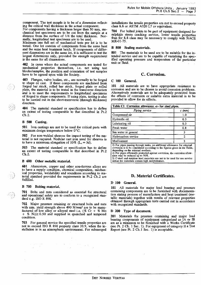
101 All materials are to have appropriate resistance to corrosion and are to be chosen to avoid corrosion problems. Alternatively materials are to be adequately protected from the effects of corrosion or suitable extra material is to be provided to allow for its effects.
Table Cl Corrosion allowance (<C>~ for steel pipes. Piping service c (mm)
Compressed air LO Hydraulic oil 0.3
Lubricating oil 0.3 Fresh water 0.8
Sea water in general 3
Hydrocarbon service 2 Mud/cement 3 1) For pipes passing through tanks, an additional allowance for external corrosion is to be considered according to the figures given in the Table, depending on the external medium. 2) For pipes efficiently protected against corrosion, the corrosion allow-ance may be reduced up to 50%. 3) C-steel and stainless steel materials are not to be used for sea service unless the materials contain high molybdenium.
D. Material Certificates.
D 100 General.
101 All materials for major load bearing and pressure containing components are to be furnished with documentation stating process of manufacture and heat treatment (metallic materials) together with results of relevant properties obtained through appropriate tests carried out in accordance with recognized standards.
D 200 Type of docwnent.
201 Materials for pressure contammg and major load bearing components of equipment categorized as IA or IB are as a minimum to be furnished with a Works Certificate (see Pt. 2 Ch. I Sec. 1). For equipment of category II a Test Report (see Pt. 2 Ch.! Sec. I) is acceptable.
DET NoRSKE VERITAS

Rules for Mobile Offshore Units , January 1993 Page 8 - Pt.6 Ch.5 Sec.3
SECTION 3 DESIGN PRINCIPLES
Contents.
A. Principal Requirements. A 100 General. A 200 Arrangement. A 300 Environmental conditions. A 400 Loads. A 500 Design pressure and temperature. A 600 Well fluid composition. A 700 Design safety factors. A 800 Spare parts.
A. Principal Requirements.
A 100 General.
101 Systems including equipment are to be designed according to this Chapter and applied codes/standards.
102 When it is essential for the safety of the drilling plant that the function of a component is maintained as long as possible in the event of fire, materials with high heat resistance are to be used and the rating is to be verified.
103 System and equipment are to be protected against excessive loads and pressure.
A 200 Arrangement.
201 All equipment and parts which are to be operated or subject to inspection and maintenance on board are to be installed and arranged for easy access.
202 The drillfloor is to be arranged with at least two exits free from obstructions and protruding arrangements.
203 All equipment is to be located to ensure safe operation and, if located in hazardous areas, is to be suitably protected for installation in such areas. Equipment in hazardous areas are to be so protected that maximum surface temperature does not exceed 80 % of the autoignition temperature of the explosive gas/air mixture. Where autoignition temperature is unknown, max. temperature of 200°C is to be applied.
204 The systems are to be so arranged that one single maloperation or malfunction will not lead to a critical situation for personnel or the unit. Safety systems are to provide two independent levels of protection to prevent or minimize the effects of a single malfunction or fault in the process equipment and piping system including their controls. The two levels of protection are to be provided by functionally different types of safety devices to reduce the probability for common cause failures. As an example, a pressure vessel may as a primary protection against overpressure have a high pressure sensor fitted, which once activated cause the source of overpressure to be eliminated. A pressure relief valve may be fitted as the secondary protection.
205 All equipment is to be equipped with indicating instruments considered necessary for safe operation.
A 300 Environmental conditions.
301 The environmental criteria and motion characteristics of the unit, for the design conditions; operation, survival and transit, used for the classification of the unit, are to be used:
- Pt. 3 Ch. I Sec. 4 and Pt. 3 Ch. 2 Sec. 2 for drilling plants on mobile offshore units.
- •Rules for Classification of Steel Ships• Pt. 3 Ch. I Sec. 4 for drilling plants on ships.
302 Test results or other relevant documentation confirming the components' or systems' suitability for their intended purpose may be required.
303 Where applicable, the following aspects are to be taken into consideration when establishing the environmental loads:
- the unit's motions (i.e. heave, roll, pitch, sway, surge and yaw)
- wind forces - air and sea temperatures -waves - current - loads from possible snow and ice accretion - earthquake.
A 400 Loads.
401 Each part of the drilling plant is to be designed for the most unfavourable load condition, for which it is intended to be used. Applicable parts of Pt. 3 Ch. I may be used to calculate loads and loading conditions.
402 For each loading condition, and for each item to be considered, the most unfavourable combination, position and direction of loads which may act simultaneously, are to be used in the analysis. The strength analysis may be performed according to Pt. 3 Ch. !.
403 All external loads which may impair the proper function of the drilling plant and have significant influence or cause a reduction of the safety, strength and reliability, are to be considered.
A 500 Design pressure and temperature.
501 Due to internal or external conditions, the design temperature for which the component may be allowed to operate with the corresponding design pressure is to be specified with adequate margins to cover uncertainties in the prediction.
502 The consideration is to include start-up, shutdown and those abnormal conditions which are considered likely to occur.
503 When deemed necessary, studies, calculations, etc. to establish particular operational limitations not readily available, e.g. low temperature in choke and well test systems, etc. are to be presented.
A 600 Well fluid composition.
601 Due consideration is to be given to well fluid composition with regard to such phenomena as corrosion, stress corrosion cracking, erosion, fouling, etc.
A 700 Design safety factors.
701 The safety factors to be used in determination of an acceptable stress level for the various load conditions are to be established by the designer, and included in the design documentation.
702 Safety factors are to be in accordance with relevant code, standard or recommended practice for each particular component if not specified in this Chapter.
DET NORSKE VERITAS

)
703 The yield strength used in calculations is not to exceed 0,85 of the specified minimum tensile strength.
A 800 Spare parts, 801 Any spare part is to be subject to the equivalent certification as the original parts.
DET NORSKE VERITAS
Rules for Mobile Offshore Units , January 1993 Pt.6 Ch.5 Sec.4 - Page 9

Rules for Mobile Offshore Units , January 1993 Page 1 O - Pt.6 Ch.5 Sec.4
SECTION 4 SYSTEMS
Contents.
A. General. A 100 Principles.
B. Blowout Prevention System. B 100 General. B 200 Blowout preventer stack. B 300 Blowout preventer control. B 400 Diverter control. B 500 Choke manifold. B 600 Valves in drill string.
C. Marine Riser System. C 100 Kill and choke lines. C 200 Riser wellhead connector.
D. Heave Compensation and Tensioning System. D 100 Gerieral.
E. Hoisting, Rotating and Pipe Handling System. E 100 General. E 200 Hoisting. E 300 Pipe handling.
F. Bulk Storage, Drilling Fluid Circulation and Cementing System.
F 100 General. F 200 Bulk storage. F 300 Drilling fluid circulation.
G. Well Test and Flare System. G 100 System requirements.
A. General.
A 100 Principles.
101 The drilling system is to be designed to operate safely under the maximum load conditions anticipated during drilling operations, and limit the risk of any danger.
102 All components in a system, and co-operating systems, are to be satisfactorily matched with regard to function, capacity and strength.
103 Relative motion between different parts of a system is to be allowed for to the extent necessary without inducing detrimental stresses.
B. Blowout Prevention System.
B 100 General.
101 The blowout prevention system is normally to consist of at least the following:
- A diverter with a securing element for closing around the drilling equipment in the hole. Normally, two diverter lines, each sufficient to take the predicted flow are to be provided. The lines are preferably to lead to opposite sides of the unit.
- One bag-type/annular preventer. - One blind/shear ram preventer equipped with mechanical
locking device. - Two pipe ram preventers equipped with mechanical
locking devices. - Necessary control equipment as stated in 300 and 400
below.
B 200 Blowout preventer stack.
201 The blowout preventer stack is to be designed so that fluid and gas can be conducted out of the system, and so that fluid can be pumped in.
202 2 valves are to be installed close to the blowout preventer stack for each of the kill and choke lines. These valves are to allow for remote control. Where blowout preventers are installed on the sea-bed these valves are to be of the fail-safe type. The valves are to be located so that they are protected against damage from falling equipment etc.
B 300 Blowout preventer control.
301 The blowout preventers are to be connected to at least two control panels, one operated at the driller's stand. The control panels are to be connected directly to the main unit of the control system, and are not to be connected in series.
302 The second control panel is to be located at a suitable distance from the driller's stand, and is to be arranged for easy access, also when the control panel at the driller's stand is not functioning or is out of reach.
303 The control panels are to give clear indication whether the blowout preventers are open or closed. Furthermore, the panel are to indicate pressure and volume for the various functions/operations.
304 The control panels are to be fitted with visual and audible alarm signals for low accumulator pressure, for loss of energy supply, as well as for low levels in the control fluid storage tanks.
305 The main unit of the control system, including the pilot valves, is to be situated so that it is shielded from the drillfloor/cellar deck. It is, however, to be easily accessible from the drillfloor. In addition, it is to be possible to reach the unit from the outside without having to go via the drillfloor or the cellar deck.
306 The closing unit accumulators for surface BOP's are to have sufficient volumetric capacity to provide the usable fluid volume (with pumps inoperative) to close one pipe ram and the annular preventer in the stack plus the volume to open the hydraulic choke line valve.
307 The closing unit accumulators for subsea BOP' s are to have sufficient volumetric capacity to provide the usable fluid volume (with pumps inoperable) to close and open the ram preventers and one annular preventer.
308 The control system of the blowout preventers is to be designed in such a way that each of the blowout preventers have response time within acceptable limits according to recognized codes and standards.
309 The BOP stack is to be provided with two independent pods for the BOP control lines from the main control unit.
B 400 Diverter control.
401 The diverter system is to be connected to a control panel which can be operated manually from a place near the driller's stand.
402 The diverter control system is to be equipped with an interlock so that the valve in the diverter pipe which leads out to the leeward side is opened before the diverter closes around the drilling equipment.
DET NORSKE VERITAS
B 500 Choke manifold.
501 The high pressure side of the choke manifold is to have at least the same working pressure as the rated working pressure of the blowout preventer stack.
502 It is to be possible to pump mud through the choke and kill manifold up to the rated pressure of the blowout preventer stack.
503 It shall be possible to lead the returns from the choke manifold through an installed mud/ gas separator.
504 The choke and kill manifold and choke/kill lines are to be arranged so that pumping through one line and simultaneous flow return over the chokes through the opposite line is possible.
505 The choke manifold is to be equipped with the following:
- At least 3 chokes, of which one is to allow for remote control, and one for manual adjustment. It shall be possible to isolate and change each choke, if necessary, while the manifold is in use.
- One valve for each of the outlet/inlet lines, so that lines to and from the manifold can be isolated. Where high pressure/low pressure zones meet in the manifold system, 2 valves arranged in series are to be used. Manifolds for 345 bar or higher pressures are to be equipped with minimum 2 valves before each of the chokes. The working pressure of the valves are to refer to the maximum working pressure of the choke manifold.
506 The following indications are to be easily visible to the operator of the remotely controlled chokes: drill pipe pressure, the choke manifold pressure and drilling fluid pump rate. At the place of operation of the manually adjustable choke(s), only the drill pipe pressure and the choke manifold pressure are to be displayed.
B 600 Valves in drill string.
601 Means are to be provided to prevent back flow in the drill string during all drilling conditions, both disconnected and connected if not provided as specified in 602-605.
602 An upper kelly cock is to be installed below the swivel, and a lower kelly cock at the bottom of the kelly.
603 The kelly cocks are to be maintained in a serviceable condition and are to be tested concurrently with the blowout preventers.
604 The wrench or other tool used to close the kelly cock is to be kept in a readily accessible place, and its purpose and use made known to all employees who may be expected to use it.
605 An open/close drill string safety valve is to be located in open position on the drillfloor for immediate use. The valves are to be of proper size and thread configuration to fit the pipe in use at the time. This valve is to be capable of withstanding the same well surface pressures as the blowout preventers that are used.
C. Marine Riser System.
C 100 Kill and choke lines.
101 Kill and choke lines are to be provided from the blowout preventer stack and are to be connected to a choke manifold.
102 Kill and choke lines with connections, valves, etc., are to have at least the same working pressure as the rated working pressure of the blowout preventer stack.
Rules for Mobile Offshore Units , January 1993 Pt.6 Ch.5 Sec.4 - Page 11
C 200 Riser wellhead connector.
201 Emergency operation of the riser wellhead connector is to be possible from another location than the place of normal operation. The location of the control is to be so chosen so that at least one control point is likely to be accessible in the event of an emergency.
D. Heave Compensation and Tensioning System.
D 100 General.
101 Restricted flow in both directions of compensators are to be arranged to safeguard against loss of pressure fluid.
102 Air control panels and accummulators are to be fitted with safety valves.
103 Air relief lines from safety valves are to be self draining.
104 Compressed air is to be used only with non- combustible fluids.
105 One failure of a component of the riser tensioners is not to lead to overall failure of the system.
E. Hoisting, Rotating and Pipe Handling System.
E 100 General.
101 Equipment installed in the derrick and above the drilling floor is to be properly fastened.
E 200 Hoisting.
201 A safety device is to be arranged to prevent the travelling block from being run into the crown block.
202 In the event of main brake failure, the drawwork is to be equipped with an emergency stop device which is to be readily identified and easily accessible. The emergency stop device is to have the capability to stop and lower the load safely in the event of main brake failure.
203 The maximum permissible working load for a system of interdependent equipment is to refer to the weakest component of the system, e.g. winches, wire, hooks, pulleys, etc.
204 The air supply to air-powered winches is not to exceed the pressure which is sufficient to reach SWL and SWL is not to exceed 115 of the breaking load.
E 300 Pipe handling.
301 There are to be provisions for securing of drill pipe collars, tubing, rods and casing which may be racked in the derrick.
302 Storage racks are to be designed or other means provided to prevent drill collars, pipe and other tubular material from accidentally rolling/skidding off or being released from the rack.
303 All tongs are to be securely attached to the derrick, mast or a back-up post and anchored by a wire rope or stiff arm having a minimum breaking strength greater than the breaking strength of the pulling cable or chain.
304 Tongs are to be arranged with safety lines and the lines working on the side opposite the safety line are to have a minimum breaking strength greater than the force of the make-up torque.
DET NORSKE VERITAS

Rules for Mobile Offshore Units , January 1993 Page 12 - Pt.6 Ch.5 Sec.4
305 All fittings and connections are to have at least the minimnm breaking strength of the cable, wire rope or stiff arm they are attached to, and knots are not to be used to fasten cable or wire rope lines.
306 Power tong pressure systems are to be equipped with a safety relief valve.
F. Bulk Storage, Drilling Fluid Circulation and Cementing System.
F 100 General.
101 The mud mixing facilities are to be sufficient for the intended drilling program.
F 200 Bull< storage.
201 Hydraulic/pneumatic equipment is to be fitted with safety valves.
202 For bulk storage tanks in enclosed areas testable safety valves are to be used, which can be vented out of the area. Such enclosed areas are to be ventilated so that a pressure build-up will not occur in the event of a break or a leak in the air supply system.
F 300 Drilling fluid circulation.
301 Degasser and mud/gas separator are to be vented in a safe manner.
302 High pressure mud pumps are to be fitted with pulsation dampeners and safety relief valves set at the maximum allowable pressure of the systems.
303 Mud relief line from the safety valve is to be self draining.
304 The following parameters are to be indicated at the drilling console:
- Mud pump discharge pressure and rate. - Weight of mud entering and leaving the borehole.
- Pit volume, indicating the increase or decrease in drilling fluid volume.
- Drilling fluid return indicator, showing the difference in volume between the drilling fluid discharged and returned to the platform. The flowmeter is to be capable of compensating for rig movements.
- Gas content in the mud. - Weight of the drill string. - Rate of penetration and drilling depth.
305 An audio-visual alarm is to be installed to indicate abnormal conditions in pit mud volume.
G. Well Test and Flare System.
G 100 System requirements.
101 Two valves in series are to be fitted in possible bypasses of pressure reducing devices (as for example chokes).
102 Heat exchanger is to be equipped with safety valves.
103 The swivel and kelly hose (rotary hose) are not to be a part of the test line.
104 At least two complete flare lines or other devices through which any flow from the well may be directed to different sides of the drilling unit are to be arranged.
105 Any flare line or any other line downstream of the choke manifold is to have an inside diameter not less than the inside diameter of the largest line in the choke manifold.
106 Possibilities for cooling of flare burners are to be available.
107 The flare burners are to be located at a safe distance from the unit. This is normally to be documented by heat intensity calculation.
108 Where compressed air systems are used to supply burner assemblies, means are to be provided to prevent contamination of the compressed air systems by hydrocarbons.
DET NORSKE VERITAS

Rules for Mobile Offshore Units , January 1993 Pt.6 Ch.5 Sec.5 - Page 13
SECTION 5 STRUCTURAL AND MECHANICAL COMPONENTS
.\ '
Contents.
A. General. A 100 Principles.
B. Specific Component Requirements. B 100 Blowout preventer system. B 200 Marine riser system. B 300 Heave compensation system. B 400 Hoisting, rotating, and pipe handling system. B 500 Bulle storage, drilling fluid circulation and cementing
system. B 600 BOP handling system. B 700 Well test and flare system.
A. General.
A 100 Principles.
101 Components are to be designed in accordance with these Rules and recognized codes, standards or guidelines.
102 Components are to be designed with regard to their intended use, their interaction with or near other components and their safe use under all known operating conditions, including overload if anticipated.
103 Where flanges and clamp/hub connections are used consideration is to be given to external loading in addition to internal pressure.
104 Skids and components that need to be lifted for maintenance/installation are to have properly designed lifting lugs.
105 For structures such as derrick, flare boom, BOP frames etc. the charpy V-notch requirements given in Rules for Certification of Lifting Appliances apply. However, the impact energy requirement need not be higher than the value given in Sec. 2.
B. Specific Component Requirements.
B 100 Blowout preventer system.
\ 101 The shear rams are to be capable of shearing the i thickest section of the heaviest drillpipe specified for use
with the blowout preventers.
102 Pipe rams are to be designed for any hang-off loads to which they may be subjected.
103 Surface hydraulic control lines and fittings are to be capable of withstanding a fire for a period of time sufficient for necessary operation of the BOPs.
104 The lower kelly cock is to be of such a design that it can be run through the BOP stack where the BOPs are not installed on the sea bed.
105 Design of diverter system is to take account of possible erosion during operation.
106 Valves in the diverter system are to be capable of operation under worst predictable conditions.
B 200 Marine riser system.
201 Hydraulically operated wellhead, riser, and choke/kill line connectors are to have redundant mechanisms for unlock and disconnect. The secondary unlock mechanism may
be hydraulic or mechanical but is to operate independently of the primary unlocking mechanism.
B 300 Heave compensation system.
301 Hydraulic cylinders and accumulators are to be designed for both internal pressure loads and loads as a result of their function as structural members.
B 400 Hoisting, rotating, and pipe handling system.
401 Wire clamps are to be of approved type with 2 gripping areas. The number of clamps is to be in accordance with AP! RP9B.table 2.1 however, not less than 3.
402 Where plastic covered wire is used special consideration is to be given to the number and type of clamps used.
403 Individual components such as sheaves, hooks, shackles, wire slings, permanent attachments, etc. are to be marked with the maximum permissible working load (SWL).
404 All air winches in the derrick, on drillfloor, cellar deck and catwalk are to be shielded and marked with the maximum permissible working load (SWL).
405 Winches are to have an automatic brake which comes into operation when the power supply fails. The brake is to be able to stop the winch at full speed when lowering the maximum load.
406 Winches are to be fitted with an operating handle which will return automatically to the stop position when not being operated. The stop position is to be clearly marked.
407 Winches used for the hoisting of personnel are to be designed with fixed operation up and down (no free fall with brakes).
408 Racking foundations and storage racks are to be designed to withstand the maximum anticipated load of racked pipe, drill collars and other intended loads.
409 Design of casing stabbing arrangement is to provide for the following safety features:
- automatic stop when raising/lowering handle is released. - an emergency stop device to be activated in the event of
failure of the hoisting mechanism. - where a stabbing board arrangement is fitted an additional
mechanical locking device is to be provided.
B 500 Bulk storage, drilling fluid circulation and cementing system.
501 All bulk storage tanks are to be equipped with safety valves/rupture discs to prevent damage due to overpressure. Rupture discs are only to be used for bulk storage tanks in open areas or if fitted with a relief line to an open area.
502 The design of atmospheric vessels is to take account of the static pressure developed by vent pipes or similar connections where such are fitted.
DET NORSKE VERITAS

Rules for Mobile Offshore Units , January 1993 Page 14 - Pt.6 Ch.5 Sec.6
B 600 BOP handling system. 601 Design of the BOP carrier is to take account of loads resulting from transportation and stowing of the BOP.
B 700 Well test and flare system. 701 The flare boom structure is to be designed for both operating and stowed condition.
702 In designing the flare/bnmer boom structure due consideration is to be given to thermal loads during flaring.
DET NORSKE VERITAS

Rules for Mobile Offshore Units , January 1993 Pt.6 Ch.5 Sec.6 - Page 15
SECTION 6 PIPING
Contents.
A. General. A 100 Application.
B. Piping Design. B 100 General. B 200 Hard piping design. B 300 Flexible piping. B 400 Valves and other piping parts. B 500 Piping connections.
C. Supporting Elements. C 100 General.
A. General.
A 100 Application.
101 Piping includes pipes, flexible piping such as expansion elements and flexible hoses, other parts such as valves and fittings, piping connections such as welded connections, bolted flanges, clamps, couplings, gaskets etc. and hangers and support brackets.
B. Piping Design.
B 100 General.
101 For piping not covered by the applied recognized codes or standards a combined stress calculation may be used.
102 Relevant factors and combination of factors are to be taken into account during design when evaluating possible failure modes such as, but not limited to:
- corrosion/erosion types - vibration, hydraulic hammer - pressure pulsations - abnormal temperature extremes - impact forces - leakages ..
B 200 Hard piping design.
201 Pipe calculations are to ensure that the pipes have the necessary strength (i.e. strength thickness) during their life of operation.
202 If a combined stress calculation according to von Mises theory is applied, the equivalent combined stress is at no point of the piping wall to exceed 60 % of the minimum specified yield strength of the material. The minimum yield strength (" r) of any material is to be taken as the smaller of:
- minimum upper yield strength - yield strength at 0,2 % offset - 0,8 x minimum tensile strength of the material (uh).
The equivalent combined stress as defined by von Mises is:
I 2 2 2 "• = 0,707 -y (u0-u1) + (u1 u,) + (u,-u0)
where
ac = equivalent (von Mises) combined stress cro = circumferential or hoop stress
"' = longitudinal or axial stress err = radial stress.
The calculations for cro, a1 and err may be based on Lame's equations for thick cylinders.
203 The minimum design wall thickness (I) of all piping is to account for:
- bending allowances, see 204 - allowances for threads, see 205 - corrosion allowances, see 206 - erosion allowances, see 208.
The minimum wall thickness of a straight or bent pipe is not to be less than:
t = t0 + allow~ces If pipes are to be bent, the minimum wall thickness before bending is not to be less than:
10 + b
where
lo strength thickness (calculated from design code or 202)
b = bending allowance.
204 When the allowance for bending b is not determined by a more accurate procedure, or when the bending is not carried out by a bending procedure ensuring a control of the wall thickness, the allowance for bending is not to be less than
where
I D b=25 R to
•
D = outer diameter of pipe R = radius of the bend lo = strength thickness.
If the bending ratio DIR is not given this ratio is to be taken equal to 1:3.
205 The calculated minimum strength thickness of piping which is to be threaded is to be increased by an allowance equal to thread depth, dimension h of ANSI B2. l or equivalent is to apply. For machined surfaces or grooves, where the tolerance is not specified, the tolerance is to be O.Smm in addition to the specified depth of cut.
206 For steel materials the corrosion allowance is to be as specified in Table Cl, Sec. 2 C 100. For pipes of copper, brasses, copper-tin alloys and Cu- Ni alloys with Ni-content < 10% the corrosion allowance is to be 0.8mm. For pipes of Cu-Ni alloys with Ni- content ~ 10 % the corrosion allowance is to be O.Smm. For media with small corrosive action in respect of the material employed, the corrosion allowance may be reduced to zero. For pipes where there is a risk of heavy corrosion a greater corrosion allowance may be required.
207 The value of I does not account for any negative manufacturing tolerance, therefore the nominal wall thickness t,., is not to be less than:
I = I • l-a/100
DET NORSKE VERITAS

Rules for Mobile Offshore Units , January 1993 Page 16 - Pt.6 Ch.5 Sec.6
where
a = percentage negative manufacturing tolerance.
208 Where piping is likely to be exposed to erosion e.g. mud/cement system, an erosion allowance is ·ta be specified to take into account likely service conditions.
B 300 Flexible piping.
301 The locations of flexible piping elements are to be clearly shown in the design documentation.
302 Flexible piping parts approved for their intended use may be installed in locations where hard piping is unsuitable.
303 Flexible piping elements are to be accessible for inspection.
304 Means are to be provided to isolate flexible piping if used in systems where uncontrolled outflow of medium is critical.
305 The bursting pressure for flexible hoses is to be at least 4 times the maximum working pressure. Lower bursting pressures may be specially considered for hoses with high pressure rate and large nominal bores.
306 Flexible hoses and non-metallic expansion joints for hydrocarbon systems have to qualify a fire endurance test according to the Society's •Classification Note No. 6.1 (test method B)» or equivalent. The flexible hose has to maintain its integrity and functional properties for the same period as required for the total piping system and components.
307 Piping in which expansion joints or bellows are fitted is to be adequately adjusted, aligned and clamped. Protection against mechanical damage may be reqnired if found necessary.
308 End fittings are to be designed and fabricated according to recognized codes/standards.
B 400 Valves and other piping parts.
401 Screwed-on valve bonnets are not to be used for valves with nominal diameter exceeding SOmm.
402 Screwed-on valve bonnets are to be secured against loosening when the valve is operated.
403 Indicators are to be provided to show open and closed position of the valve.
404 Closing time of valves is to be selected so that no detrimental stresses are introduced to piping due to hydraulic hammering.
405 Piping parts not covered by recognized standards are to be approved for their intended use. Drawings are to be submitted for approval, and supported by stress calculations. Application, type of medium, design pressure, temperature range, materials and other design parameters are to be given. If the parts have a complicated configuration that makes theoretical calculations unreliable, the parts may be
accepted based on certified prototype proof test reports that prove their suitability for the intended use. ·
B 500 Piping connections.
501 The number of detachable pipe connections are to be limited to those which are necessary for mounting and dismantling. The piping connections are to be in accordance with the applied code or standard or are to be approved for their intended use.
502 Joints of pipes with outer diameter of Simm and above are normally to be made by buttwelding, flanged, or screwed union where the threads are not part of the sealing. Joints for smaller sizes may be welded or screwed and seal welded if not intended for corrosive fluids. Tapered threads and double bite or compression joints may be accepted after special consideration.
503 If the piping system is rated for 207 bar (3000 psi) or more, ordinary threaded connections are not to be used.
504 Weld neck flanges are to be forged to a shape as close to the final shape as possible.
505 Tapered threads are to be used on couplings with stud ends where such couplings are permitted.
506 Calculations of the reinforcement are required:
- when weldolets of unrecognized type and shape are used in the branch connection.
- when the strength is not provided inherently in the components in the branch connection.
Guidance note: ANSI/ASME B 31.3, 304.3 may be referred to.
---e-n-d---o-f--G-u-i-d-a-n-c-e-n-o-t-e---
C. Supporting Elements.
C 100 General.
101 Piping is to be supported in such a way that its weight is not taken by connected machinery or that heavy valves and fittings do not cause large additional stresses in adjacent pipes.
102 Axial forces due to internal pressure, change in direction or cross-sectional area are to be taken into consideration when mounting the piping.
103 The support of the piping is to be such that detrimental vibrations will not arise in the system.
104 Attachments welded directly to pipes are not to be used on piping rated 207 bar (3000 psi) or above. Gland type (stuffing box) penetrations are to be applied for pipe penetrations through decks/bulkheads.
105 Attachments welded directly to pipes rated below 207 bar (3000 psi) are to be avoided. Where this cannot be avoided, doubling plates are to be used, or the support is, by other means, to be welded to the pipe in a way that introduces the minimum of stresses to the pipe surface from forces acting on the support.
DET NORSKE VERITAS

Rules for Mobile Offshore Units , January 1993 Pt.6 Ch.5 Sec.7 - Page 17
SECTION7 MANUFACTURE, WORKMANSHIP AND TESTING
Contents.
A. General. A 100 Application. A 200 Quality assurance and quality control. A 300 Marking.
B. Manufacture. B 100 Welder's qualification. B 200 Welding. B 300 Heat treatment. B 400 Pipe bending.
C. Non-destructive Examination (NDE). C 100 General. C 200 Derrick, flare booms and B.O.P. handling
D. Testing. D 100 Testing of weld samples. D 200 Pressure testing. D 300 Load testing. D 400 Functional testing.
A. General.
A 100 Application.
101 This Section covers equipment, structures and systems during fabrication, installation and final testing onboard.
102 Item A 200 covers the equipment, structures and systems supplied by the manufacturer to the main yard. For quality assurance requirements to main yard, see Pt.I Ch.!.
103 Equipment, structures and systems are to be fabricated, examined and tested according to this Section, design documentation and applied code and standard.
A 200 Quality assurance and quality control.
201 The manufacturer is to have the necessary production facilities, qualifications, procedures and personnel to ensure that the product will be manufactured to the specified requirements.
202 For category IA equipment, the manufacturer is to ·) demonstrate that requirements in A 201 are complied with.
A 300 Marking.
301 All equipment is to be clearly marked with identification and serial number, relating the equipment to certificates and fabrication documentation.
Guidance note: Low stress stamping may be required for certain materials. Paint markings may be accepted, but care must be exercised during handling and storage to preserve the identification.
---e-n-d---o-f---G-u-i-d-a-n-c-e---n-o-t-e---
B. Manufacture.
B 100 Welder's qualification.
101 Welding of pressure containing components and piping systems, and welding of load carrying equipment and structures is to be carried out by approved welders only.
102 Approval of welders is to be in accordance with Pt.2 Ch.3 or the applied design code.
103 Welders already approved to another corresponding code than design code may be accepted by the Society if properly documented.
104 The manufacturer is to supply each welder with an identification number or symbol to enable identification of the work carried out by each particular welder.
B 200 Welding.
201 All welding as specified in B 101 is to be performed in accordance with approved welding procedure specification (WPS).
202 A welding procedure qualification test (WPQT) may be required when makers intend to use WPS for which there exists insufficient experience at plant or elsewhere or if new complicated structural details are used. The extent of the procedure test is to be agreed upon with the Society before the work is started. For details of performance of WPQ, limitations etc. see Pt.2 Ch.3 Sec.2.
203 A welding production test (WPT) may be required by the surveyor during fabrication to verify that the produced welds are of acceptable quality.
204 The welding of drilling derrick and flare booms are to be in accordance with relevant section of .:Rules for Certification of Lifting Appliances•.
205 Butt welded joints are to be of the full penetration type. Special provisions are to be taken to ensure a high quality of the root side.
206 If supports and similar non-pressure parts are welded directly to pressure retaining parts, the welding requirements for the pressure retaining parts are to be adhered to.
207 Welding repairs are to be performed according to an approved repair procedure.
208 Repair welding is normally to be carried out with electrodes giving a weld deposit compatible with the parent material.
B 300 Heat treatment.
301 The component is to be heat treated after forming and/or welding if required by the applied code or standard or if found necessary to maintain adequate notch ductility and to avoid hydrogen induced cracking.
302 Rate of heating and cooling, hold time and metal temperature are to be properly recorded.
303 A normalizing heat treatment is required for hotformed parts, unless the process of hot forming has been carried out within the appropriate temperature range, duration and cooling rate.
304 The heat treatment for cold-worked materials is to be selected with respect to the degree of plastic deformation in the material.
305 Preheating and/or post weld heat treatment is to be used when necessitated by the dimensions and material composition.
306 Post weld heat treatment (PWHT) is normally to be performed in a fully enclosed furnace. Local PWHT may be performed on simple joints when following an approved procedure.
DET NORSKE VERITAS
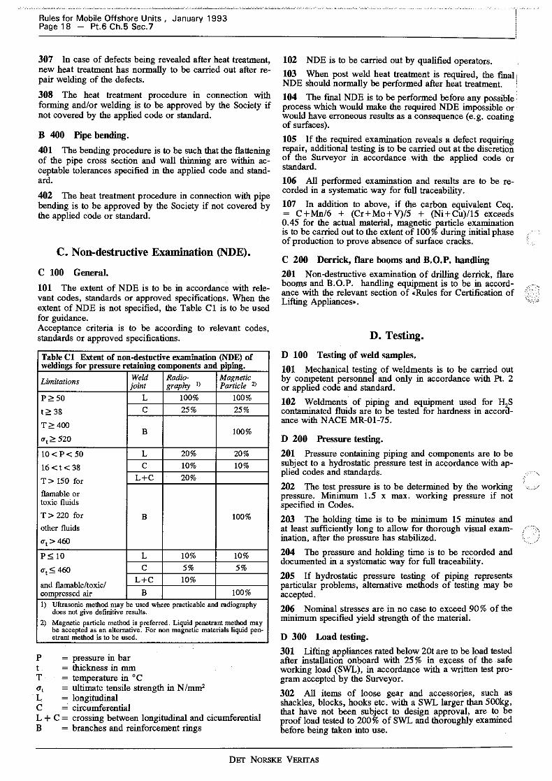
Rules for Mobile Offshore Units , January 1993 Page 18 - Pt.6 Ch.5 Sec. 7
307 In case of defects being revealed after heat treatment, new heat treatment has normally to be carried out after repair welding of the defects.
308 The heat treatment procedure in connection with forming and/or welding is to be approved by the Society if not covered by the applied code or standard.
B 400 Pipe bending.
401 The bending procedure is to be such that the flattening of the pipe cross section and wall thinning are within acceptable tolerances specified in the applied code and standard.
402 The heat treatment procedure in connection with pipe bending is to be approved by the Society if not covered by the applied code or standard.
C. Non-destructive Examination (NDE).
C 100 General.
101 The extent of NDE is to be in accordance with relevant codes, standards or approved specifications. When the extent of NDE is not specified, the Table Cl is to be used for guidance. Acceptance criteria is to be according to relevant codes, standards or approved specifications.
Table Cl Extent of non-destuctive examination (NDE) of weldings for pressure retaining components and piping.
Limitations Weld Radio- Magnetic joint graphy 1) Particle Z)
p"' 50 L 100% 100%
t<;: 38 c 25% 25%
T <! 400 B 100%
ut~ 520
lO<P< 50 L 20% 20%
16<t<38 c 10% 10%
T> 150 for L+C 20%
flamable or toxic fluids
T> 220 for B 100% other fluids
O't > 460
p s; 10 L 10% 10%
uts; 460 c 5% 5%
and flamable/toxic/ L+C 10%
compressed air B 100% 1) Ultrasonic method may be used where practicable and radiography
does not give definitive results.
2) Magnetic particle method is preferred. Liquid penetrant method may be accepted as an alternative. For non magnetic materials liquid pen-etrant method is to be used.
P = pressure in bar t = thickness in mm T = temperature in °C a, = ultimate tensile strength in N /mm2
· L = longitudinal C = circumferential L + C = crossing between longitudinal and cicumferential B = branches and reinforcement rings
102 NDE is to be carried out by qualified operators.
103 When post weld heat treatment is required, the final NDE should normally be performed after heat treatment.
104 The final NDE is to be performed before any possible process which would make the required ND E impossible or would have erroneous results as a consequence (e.g. coating of surfaces).
105 If the required examination reveals a defect requiring repair, additional testing is to be carried out at the discretion of the Surveyor in accordance with the applied code or standard.
106 All performed examination and results are to be recorded in a systematic way for full traceability.
107 In addition to above, if the carbon equivalent Ceq. = C+Mn/6 + (Cr+Mo+V)/5 + (Ni+Cu)/15 exceeds 0.45 for the actual material, magnetic particle examination is to be carried out to the extent of 100% during initial phase of production to prove absence of surface cracks.
C 200 Derrick, flare booms and B.O.P. handling
201 Non-destructive examination of drilling derrick, flare booms and B.O.P. handling equipment is to be in accordance with the relevant section of •Rules for Certification of Lifting Appliances•.
D. Testing.
D 100 Testing of weld samples.
101 Mechanical testing of weldments is to be carried out by competent personnel and only in accordance with Pt. 2 or applied code and standard.
102 Weldments of piping and equipment used for H S contaminated fluids are to be tested for hardness in accoraance with NACE MR-01-75.
D 200 Pressure testing.
201 Pressure containing piping and components are to be subject to a hydrostatic pressure test in accordance with applied codes and standards.
202 The test pressure is to be determined by the working pressure. Minimum 1.5 x max. working pressure if not specified in Codes.
203 The holding time is to be minimum 15 minutes and at least sufficiently long to allow for thorough visual examination, after the pressure has stabilized.
204 The pressure and holding time is to be recorded and documented in a systematic way for full traceability.
205 If hydrostatic pressure testing of piping represents particular problems, alternative methods of testing may be accepted.
206 Nominal stresses are in no case to exceed 90% of the minimum specified yield strength of the material.
D 300 Load testing.
301 Lifting appliances rated below 20t are to be load tested after installation onboard with 25 % in excess of the safe working load (SWL), in accordance with a written test program accepted by the Surveyor.
302 All items of loose gear and accessories, such as shackles, blocks, hooks etc. with a SWL larger than 500kg, that have not been subject to design approval, are to be proof load tested to 200 % of SWL and thoroughly examined before being taken into use.
DET NORSKE VERITAS
This may be documented with test certificate issued by an independent recognized body.
303 The flare boom is to be tested after installation with an overload of 25 % related to the required weight of burner and spreader. This overload test is to demonstrate that the boom is capable of carrying out the motions such as slewing, hoisting etc. (as relevant).
304 B.O.P. handling systems and lifting appliances rated above 20 tons may be tested with an overload of 5t in excess of safe working load.
Guidance note: Drilling hoisting equipment (main hoist) that is designed and
Rules for Mobile Offshore Units , January 1993 Pt.6 Ch.5 Sec.7 - Page 19
fabricated in accordance with the requirements to category IA and IB in the Rules may be accepted without a proof load test.
--e-n-d--o-f--G-u-i-d-a-n-c-e--n-o-t-e---
D 400 Functional testing.
401 A functional test under working conditions is required for systems in accordance with written test programs accepted by the Surveyor.
402 Blowout preventers with control system are to be tested for capacity and performance. Shear rams are to be tested to show that they will be capable of shearing the heaviest and toughest drill pipe to be used.
DEr NORSKE VERITAS
Rules for Mobile Offshore Units , January 1993 Page 20 - Pt.6 Ch.5 App.A
APPENDIX A SUPPLEMENTARY REQUIREMENTS OF THE NORWEGIAN PETROLEUM DIRECTORATE (NPD) AND THE NORWEGIAN MARITIME DIRECTORATE
(NMD)
Contents.
A. General A 100 Application A 200 Documentation A 300 Codes and Standards
B. Design Principles B 100 Arrangement B 200 Barriers B 300 Instrumentation B 400 Risk Analysis
C. Systems C 100 Blowout Prevention System C 200 Hoisting C 300 Drilling Fluid Circulation C 400 Kill and Choke Systems C 500 Well Test Systems
A. General
A 100 Application
101 Drilling plants complying with the requirement of the Rules and the supplemental requirements contained in this Appendix will, after completion of the necessary design reviews and surveys be assigned the following additional class notation:
DRILL (NJ
102 The supplemental requirements contained in this Appendix have been tranferred from the Norwegian Maritime Dictorate (NMD) regulations of 13 May 1987 concerning drilling installations and equipment, etc. on Mobile Offshore Units which are registered or will be registered in a Norwegian Ship Register as per May 1987 and NPDs •Regulations concerning drilling and well activities and geological data collection in the petroleum activities» applicable as of May, 1 1992. For specific entry into force and transitional provisions as per NPD, reference is made to section 5 in the subject regulation.
Guidance note: The authorities have specific requirements to operations, personnel, work environment which are outside the current scope of these rules.
---e-n-d--o-f---G-u-i-d-a-n-c-e---n-o-t-e---
103 Practice in relation to the repealed drilling regulations may lead to a need for older installations and equipment to a certain extent be upgraded in order to meet current requirements.
A 200 Documentation
201 Documentation is required for ensuring and documenting that engineering, construction and installation of drilling equipment and installations are carried out safely and in accordance with the regulations.
202 Equipment considered to be of major siguificance to the safety of personnel, well integrity and installations is to be documented seperately. This equipment, which is listed
as equipment of categories IA and IB, also includes the following:
- running tools - drill string - test string - casing.
203 The documentation system of the operator may make use of documentation and documentation systems already established with contractors, suppliers, and classification society to prepare and keep necessary documentation on file.
In accordance with the current practice the documentation applicable to the above shall as a minimum include:
a) name of equipment
b) production number
c) name of manufacturer and supplier
d) description of design and manufacture, including safety factors used
e) verification of design/strength control
f) material certificates and confirmation as to where materials have been used
g) welding procedure specification
h) statement of manufacture and inspection signed by manufacturer and Society's Surveyor
i) report from testing including testing conditions, and information on how testing has been carried out
j) verification of design assumptions with regard to strength, carried out by the Society
k) suppliers operation and maintenance specifications, with indication of operational criteria/limitations
1) marking of equipment
m) updating of items a) to 1) in case of modification of equipment.
204 Experience has shown that the operator may be faced with the problem that drilling equipment of major significance to safety is lacking documentation. This may cause to a certain extent quite significant deviation procedures in order to verify compliance with the requirements of the regulations.
With regard to verification of such equipment, adequate deviation procedure will normally include, but not be limited to, the following:
a) analysis of elements (chemical composition)
b) hardness measurements
c) NDE(MPI, replica etc.)
d) confirmation from manufacturer that the equipment is produced in accordance with recognized codes and standards
e) equipment history.
DET NORSKE VERITAS

A 300 Codes and Standards
301 The most current editions of standards and calculation rules should always be used as reference basis. Exclusive use of the standards alone will however not guarantee an acceptable safety level. The standards must consequently be seen in conjunction with necessary supplemental requirements.
302 With regard to electrical installations dealt with in standards, the Regulations concerning electrical installation in the petroleum activities will be applicable.
B. Design Principles
B 100 Arrangement
101 The term well control equipment includes all equipment used for drilling, well control, completion and well workover.
102 Work areas in connection with drilling and well activities shall be arranged so as to ensure totally adequate safety for personnel and operations. This will include measures to limit the possibilities for injury or damage caused by falling objects, work load damage due to heavy and difficult work operations and various types of bruise or contusion injury through handling of drilling equipment.
103 All spaces and work areas where people normally go shall be equipped with at least two independent escape routes.
104 Areas for work or other purpose shall be suitably lighted.
105 Equipment and components should to the extent possible have independent securing devices against falling down and thereby causing damage or injury.
106 Floors in all work areas and spaces where people normally go shall have adequate non-slip qualities. Also there shall he no protrusions constituting a hazard to people. Where such protrusions nevertheless exist, they should be conspicuously marked and/or should be equipped with
) safety devices.
107 Decks and work areas shall be equipped so that water, oil spillage, drilling mud etc. is easily drained off. Spillage damaging to the environment shall be capable of being collected into an installed slop tank with effective drainage to a collecting device.
108 Work areas and equipment should be secured and protected against unfavourable effects of the external environment.
109 When safety devices are activated in order to avoid pressure exceedance, pressure relief shall not be capable of causing injury to persons, to the environment or to material.
110 The installation shall be fitted with accessible equipment ensuring that drilling and well control personnel are able to carry out a safe operation/shutdown on the installation in the event of a blowout. Mobile installations shall be capable of being moved from the blowout to a safe area.
111 Measures shall be taken to ensure that the working environment is fully adequate with regard to exposure to noise and health hazardous substances.
112 Mobile work platforms are regarded as lifting equipment and shall otherwise be subjected to safety requirements equivalent to those applicable to other transportation equipment.
Rules for Mobile Offshore Units , January 1993 Pt.6 Ch.5 App.A - Page 21
B 200 Barriers
201 During drilling and well activities at least two independent and tested barriers shall as a rule be available in order to prevent an uuintentional flow from the well.
202 The barriers shall be designed so as to enable rapid reestablishment of a lost barrier.
203 The barriers shall be defined and criteria for failure shall be determined. The position/status of the barriers shall be known at all .times.
204 Installation must be equipped with an independent power source to enable the drilling fluid to be mixed and circulated in order to maintain/re-establish complete well control in a situation where a well barrier is lost and the ordinary power source of the installation has failed.
Recognized equipment needed to comply with the requirement relating to circulation of drilling fluid will be for the mud pumps of the installation to be supplied with power from two independent power sources, e.g. from an independent electric generator. The independent electric generator may be replaced by a diesel driven pump (e.g. a cement pump) with a sufficient working pressure and capacity for circulation of drilling fluid.
205 The diesel driven pump is to be run and can be started independently of the ordinary power supply of the installation.
206 An arrangement with a divided engine room will be able to satisfy the requirement of adequate availability of power supply if power supply damage/failure from one engine room can be compensated by power supply from the other. Both engine rooms will then be regarded as a normal power source.
207 When a feeding pump for the mud pumps is required, it must be run independent of the ordinary power supply of the installation.
208 Functional requirements with regard to barrier philosophy, suitability, operative capability and ability for mobilization of the drilling and well control equipment shall be defined at an early stage of the design phase. All systems and components shall meet these requirements.
B 300 Instrumentation
301 Instruments of significance to safety shall be inspected and calibrated or replaced in accordance with a specified programme. Verification of inspections and callibrations shall be documented.
302 Instruments for monitoring and registration of data significant to safety shall be connected to an emergency source of power.
303 Instruments should be selected so that the reading gives an accuracy of 1 % at pressure conditions 50 % of maximum working pressure. A corresponding accuracy should apply to volume control. The operator should define accuracy requirements in the instrumentation for return flow.
304 Instruments should be arranged with several scales in order to increase the accuracy of readings.
305 The logging instrument and other tools including cables and pipes used for transfer of well parameters shall correspondingly be capable of withstanding the most extreme parameters in the well (e.g. pressure, temperature) to which the equipment may be subject.
DET NORSKE VERITAS

Rules for Mobile Offshore Units , January 1993 Page 22 - Pt.6 Ch.5 App.A
B 400 Risk Analysis
401 Risk analyses shall be carried out to expose the consequences of single failures or sequential failures that may occur during operation in order that risk reducing measures may be taken.
402 When risk reducing measures are implemented, probability reducing measures shall take priority over consequence reducing measures.
C. Systems
C 100 Blowout Prevention System
101 During design, fabrication, installation and operation of control systems, the overall arrangement of the installation with regard to area classification and principal safety philosophy shall be taken into account.
102 Blowout preventers shall be designed and capable of being activated in such a way as to ensnre that their function as a barrier can be maintained. They are to be installed and operative at a sufficient early stage of operation.
103 A blowout preventer is also to be designed to perform the necessary function connected with reestablishing a barrier, in that it is possible to carry out controlled circulation of fluid and gas out of the system, and allow fluid to be pumped in. This further entails that the valves must be arranged so as to allow formation fluid to be conducted to the choke manifold by way of two independent piping systems. The piping systems are to be designed so that circulation for well control can be carried out with the drillstring suspended in the blowout preventer and the shear ram preventer closed.
104 Responsible personnel shall be capable of activating the blowout preventer from control panels at suitable locations on the installation. The control panels shall be connected to the control system by independent activating system.
105 According to current practice the following normally occurs:
a) Prior to drilling out of surface casing, a blow-<Jut preventer system shall be installed consisting of at least one remote control annular preventer, one shear ram preventer and one pipe ram preventer. The blowout preventer system shall furthermore be connected to a choke manifold and a suitable diverter system.
b) Prior to drilling out of intermediate/protective casing and liner, a complete blowout preventer system shall be installed and connected to the kill/choke manifold.
c) During drilling with blowout preventer on the sea bed, a diverter system shall in addition be installed. The diverter system shall be fitted with a shutdown device and a suitable diverter pipe arrangement to counteract undesired spread of hydrocarbons on board the installation.
106 For blowout preventer systems installed on the sea bed, a marine riser shall also be fitted. Kill and choke lines from the blowout preventer stack connected to the kill/choke manifold shall be installed.
107 Measures shall be taken to enable effective securing of the well. In the case of mobile installations, disconnection of the riser from the blowout preventer on the sea bed shall be possible in the event that an uncontrolled operational situation should occur.
108 In the calculation of time for necessary shutdown by means of BOP's and subsequent disconnection, possible drifting of the installation and associated riser angle under
possible operational and environmental conditions must be taken into account.
109 In the case of dynamically positioned installations account must inter alia be taken of situation with a possibl~ uncontrolled disconnection at full engine power. An electrohydraulic sequentially operated quick disconnection system ensuring shutdown by means of a shear ram, as well as opening and jackup of the lower riser anchor for disconnection is to be arranged. At a depth of about 400 metres, it should be possible for the abovementioned sequence to be carried out within 30 seconds when dynamically positioned drilling installations are used.
110 A control panel fitted with a securing device against unintentional operation of essential functions (e.g. shear ram, wellhead connection) is to be installed.
111 The main unit of the control system must be located in a safe area in order to avoid exposure in the event of an uncontrolled well situation. N orrnally this will entail that the main unit cannot be located on the drillfloor.
112 Accumulators with sufficient capacity for three operations (closing, opening, closing) of all installed BOP valves plus 25 % of the volume of one closing operation for each of blowout preventers are required. In calculating accumulator capacity, the minimum permissible operating pressure is 14 bar (200 psi) above normal preloading pressure for propellant gas. There must be a remaining accumulator pressure sufficient to carry out cutting of the drillstring after having used a volume corresponding to:
a) closing and opening of one annular preventer;
b) closing, opening and closing of one pipe ram preventer. In the case of mobile installations, there shall in addition be sufficient pressure to carry out disconnection of the riser package (LMRP) after cutting of the drillstring.
Alternately a dedicated shear ram auxiliary pressure system may be installed for cutting of drillstring. Regulators in the system shall remain unaffected in the event of loss of power supply (e.g. loss of compressed air).
113 When calculating accumulator capacity for subsea blowout preventers, corrections must be made for hydrostatic pressure of a sea water column, as well as for sea temperature.
114 Response time for closing of blowour preventers, when located on the sea bed, will be up to 45 seconds. Response time refers to the time it takes from the closing functions are activated from the panel until BOP is in closed position.
115 Corresponding response time when the blowout preventers are located on the installation is 30 seconds. (In the case of annular preventers exceeding 20 11
, however, the response time may be up to 45 seconds).
116 When drilling with blowout preventer system installed on the sea bed, an accoustic or an alternative control system for operation of pipe ram preventers, shear ram preventer and connection for marine riser shall in addition be installed. The sub-sea accumulators shall have sufficient capacity for closing of two (2) pipe ram preventers and one (1) shear ram preventer, as well as opening of the riser connection, plus 50 %.
117 For a subsea stack, the necessary loading pressure for the operation depth in question shall be used as basis for calculating the capacity. The accoustic accumulators shall have sufficient pressure for cutting the drillstring, after having closed a pipe ram preventer. In addition, the pressure shall be sufficient to carry out disconnection of the riser package (LMRP) after cutting of the drillstring has been completed. A portable unit (which can be handled by one person) shall be available for operation of the abovemen-
DET NORSKE VERITAS
.--_.- \
-. ; _/

tioned functions in the event of evacuation from the platform.
118 Disconnection at wellhead connection will not be an alternative in a crisis situation, and consequently this function is not to be available on the ordinary operations panels from where the blowoUt preventers are operated.
119 The BOP choke & kill valves shall be hydraulically operated and of remote control type. When the blowout preventer stack is installed on the platform and easily accessible, one (1) of the said valves may nevertheless by manually operated and without remote control.
120 If the blowout preventer system is installed on the sea bed, the valves shall be of a <fail-safe closed• make and shall be capable of closing during dynamic flow conditions.
121 The valves are to be covered by the monitoring and control system of the blowout preventer.
122 The kill and choke lines shall be connected to a choke manifold. It must be possible to connect the choke manifold to the drilling fluid manifold and the cementing unit.
123 The kelly cocks/IBOP's and safety valves shall be capable of being connected and operated during possible return flow and pressure from the well.
124 When a top drive rotation system is used, at least one !BOP shall be capable of remote operation.
125 When blowout preventers are installed at the wellhead with remote control connection, disconnection shall only be possible from the main control panel and from hosedrum manifold.
126 Hosedrum manifolds shall be secured against unintentional operation during normal operations.
127 It shall be possible to operate the control systems from independent panels at convenient locations. Reduction of the possibilities for and the consequences of operator failure shall be emphasized in the design of control systems.
128 1n the event of failure in the control system, components with critical functions shall remain or move towards a safe position.
) 129 1n the case of mobile installations the system shall be fitted with an alternative disconnection device which shall be possible to activate in the event of loss of primary function.
·1
130 Control panels shall be logically designed and shall indicate the position of various valves , the necessary parameters for the individual functions/operations and shall be fitted with necessary alarms. Indication of status for the wellhead connection shall be on the driller's control panel as well as on the additional operations panel.
131 No operation entailing the running of any tool, cable, line or pipe through a barrier, shall be initiated until the safety systems are qualified for cutting, sealing and disconnection.
132 During drilling of the top hole section with riser/conductor, a diverter system shall be installed with marine riser and be operative prior to any drilling in a formation where shallow gas may be encountered. In case of a jack-up type drilling installations, conductor casing is regarded as a marine riser.
1~3 Control systems for activating diverter system must be easily accesible and be capable of being activated from a location independent of and at a safe distance from the drillfloor/cellar deck.
Rules for Mobile Offshore Units , January 1993 Pt.6 Ch.5 App.A - Page 23
134 Diverter systems shall be equipped with elements that secure closing with the drillstring in the hole.
135 Diverter must be designed to operate irrespective of wind direction, and will normally have to consist of two pipes leading out to the opposite sides of installation.
136 Diverter piping should be straight and without bends.
137 Well casing shall be designed, planned, and carried out in such a way that full control of the well can be maintained at all times. Casings shall be of such quality that they can withstand particularly corrosive media in the well (H2S,C02 etc), if they can be expected to be exposed in such environment.
138 Casing shall be pressure tested after having been installed and cemented. The test pressure for each casing string shall correspond to the maximum calculated inside pressure to which the casing may be subject, without exceeding 85 % of the maximum working pressure of the casing. The test pressure shall be kept stable for at least 10 minutes.
C 200 Hoisting
201 With regard to recognized standard for derrick andsubstructure, reference is made to the Norwegian Petroleum Directorate's Regulations for loadbearing structures.
202 1n the application of the Norwegian Petroleum Directorate's Regulations for loadbearing structures to derrick and sub_structure, special operational or maintenance aspects shall be taken into account during design, fabrication and operation, e.g.:
a) additional wind loads during storage of drill pipes in the derrick;
b) special operational loads during driving of conductor, jarring or similar.
203 If the regulations for cranes etc. are used as recognized standard, consideration should in addition be given, with reference to operational area, to the need for more frequent inspections, test or examinations.
204 The derrick is to be equipped with a ladder/elevator arrangement ensuring safe access to the different working platforms. Maximum permissible height of a continuous ladder is 9 meters. The ladders are to be equipped with safety cages as well as with rest platforms at least every 6 meters, and further comply with the regulations in force for ladders. The access from ladder/lift to rest/work platforms shall be adequately secured with self-close check port, a railing at least 1000 mm high and a foot list with a height of at least 100 mm.
205 The derrick is to be equipped with an escape arrangement leading away from the derrick to a safe area in addition to main access routes.
206 The following remote control systems are to be installed:
a) stowage, connection/disconnection and suspension of drillstring, collars and casing in the rotary table.
b) transport of drillstrings, collars, casings etc. from storage location to the drillfloor.
207 If a ventline from reconditioning unit is installed in the derrick, the top of the outlet is to be at least 4 meters above the crown block, and provision for burning of gas from ventlines is not to be installed.
DET NORSKE VERITAS

Rules for Mobile Offshore Units , January 1993 Page 24 - Pt.6 Ch.5 App.A
208 The various work platforms in derricks (including platform for installation of casings) shall be adequately equipped with safety devices and lift, stairs or ladders for safe access.
209 Lubrication points with difficult access in the drilling area, such as sheaves, should be included in a central lubrication system.
210 Winches should be equipped with a spooling arangement.
211 Maximum permissible working load for equipment which is assembled together shall refer to the weakest component of the equipment, e.g. wire, hook, sheaves, etc., and shall not exceed 20 % of the breaking load.
212 A safety arrangement that prevents the drill block from being run into the drillfloor is to be installed.
213 When winches are used for access to work locations that are particnlarly inaccessible, procednres for this should be drawn up. Recognized solutions for detail design of winches for transport of personnel may be:
a) the pulling force of the winch is adjusted to about 150 kp with associated sealing of the adjustment devices after testing/certification;
b) a wire with at least 10 mm diameter and with a safety factor against fracture of at least 10;
c) two separate and independent brakes of which one is au-tomatic;
d) slack wire system;
e) derail protection on drum and wire sheaves;
f) adequate winding of wire on drum
- e.g. by installing an automatic winding device connected to the gear/driving unit of the winch;
g) unobstructed view from operating position to the person who is transported:
h) limit switches and at least 3 turns left on the drum at maximum payout of wire;
i) manual locking of shackle;
j) emergency lowering system in the event of power failure;
k) emergency stop device
- if unobstructed view from the operating position to the person being transported cannot be achieved, the person transported should also have access to an emergency stop device. A flagman may if applicable be used;
1) transport speed approximately 1 m/s;
m) securing arrangement against uncontrolled lowering speed;
n) design in accordance with recognized standards;
o) materials documentation for all loadbearing elements with necessary certificates.
C 300 Drilling Fluid Circulation
301 Enough drilling fluid material to be able to replace at least 100 % of the well volume is to be stored (one hole volume).
302 The necessary quanlllles of drilling fluid materials shall at all times be readily accessible on board.
303 The mud system shall have adequate capacity (pumping capacity and pipe dimensions) to ensure rapid weight increase of drilling mud in an active system, and the mixing of new drilling mud in the case of instability in the well.
304 A reconditioning system with necessary equipment for separation of gas from the drilling fluid shall be installed in order to ensure the desired quality of the drilling fluid.
305 Weight and rheology of the drilling fluid shall at all times be adjustable in order that the planned properties of the fluid can be maintained.
306 The installation shall be equipped with shale shakers, desanders and desilters and centrifuges of adequate number and quality to carry out reconditioning of the mud. The mud/gas separator system must be designed to handle the maximum anticipated flow rates likely to occur in the well.
307 Continuous monitoring shall be possible of fluids which constitute a barrier or which form part of a barrier element.
308 Accessibility/availability of equipment and systems for monitoring and control of drilling fluid shall be such as to ensure that important parameters are available.
309 The installation shall be equipped with necessary sensors, indicators and alarms fitted in suitable locations, to ensure that necessary parameters for the maintenance of well control are known at all times.
310 Trip tank is to be designed to register that the well takes/gives off the right volumes. The tank should be designed so that the tank level can be read mechanically as well as electronically to the nearest 0, 1 m3 •
311 When main generator is out of service and drilling fluid is circulated by means of emergency pump, (shear/cement pump), it shall be possible to monitor the gas content of the drilling fluid, the level of the mud tanks and the return flow.
312 As a minimum the following parameters are to be registered and monitored during drilling:
a) pump pressure and rate;
b) weight of drilling fluid entering and emerging from the well;
c) pit volume (active and spare tanks);
d) volume of drilling fluid entering and emerging from the well;
e) drilling fluid temperature;
f) penetration rate and drilled depth;
g) weight of the drillstring;
h) gas content in the drilling fluid.
313 The cementing unit shall be connected to a data registration unit, measuring and recording essential data during mixing and pumping. The registration unit should at least register pressure, specific weight and volumes. Measuring should take place on the high pressure side of the pump.
314 The cementing unit with associated high pressure systems shall have the necessary capacity and working pressure to ensure that well control is maintained at all times.
315 All valves on the cementing head, as well as release mechanisms for cement plugs, shall be operable by remote control.
DET NORSKE VERITAS

316 The cementing unit is to be fitted with measuring equipment which as a minimum is able to measure and store the following parameters on a continuous basis:
a) specific weight (as measured under pressure)
b) pressure
c) rates
d) volume.
C 400 Kill and Choke Systems
401 The choke manifold shall be fitted with: At least 3 chokes, of which one shall allow for remote control, and one for manual operation.
Operation of a remote control choke manifold shall take place from a suitable panel which shall at least indicate the drillstring pressure, the choke manifold pressure, volume pumped, as well as. the drilling fluid pump rate.
Rules for Mobile Offshore Units , January 1993 Pt.6 Ch.5 App.A - Page 25
402 The manifold should also be fitted with a connection facility for an extra pressure gauge with a sufficiently detailed pressure scale (more detailed reading) to be used for circulation of formation fluid/gas.
403 It shall be possible to lead the returns from the choke manifold through an arrangement enabling efficient separation of gas from the drilling fluid.
404 A fixed piping arrangement shall in addition be connected to burner booms/diverter lines from discharge pipes on the choke manifold when the blowout preventer is to fulfill a necessary barrier function. 405 Lines/hoses between the blowout preventer stack and the choke manifold shall, together with their connections and valves on the high pressure side of the choke manifold, have a least the same working pressure as the blowout preventer stack.
C 500 Well Test Systems
501 It shall be·possible to ignite the burner from a remote control facility.
DET NORSKE VERITAS

Rules for Mobile Offshore Units , January 1993 Page 26 - Pt.6 Ch.5 App.B
APPENDIXB SUPPLEMENT ARY REQUIREMENTS OF THE U.K. HEALTH AND SAFETY
EXECUTIVE (HSE)
Contents.
A. General. A 100 Application.
B. Materials. B 100 Principles.
C. Systems. C 100 Hoisting. C 200 Well test system. C 300 Well control system.
D. Piping. D 100 Piping runs.
A. General.
A 100 Application.
101 The requirements of the Rules and the supplemental requirements contained in this Appendix apply for units which are to be assigned:
UK Certificate of Fitness by Det Norske Veritas.
This is based on the assumption, that for the areas covered by these Rules, all requirements for UK Certificate of Fitness are fulfilled provided that both the Rules and Appendix B are fulfilled. Furthermore, this assumption is based on Det Norske Veritas' interpretation of the requirements of UK Health and Safety Executive (HSE). The object is to provide information for the Applicants for Certificate of Fitness and other concerned as to how Del Norske Veritas, in its capacity as Certifying Authority, interprets HSE requirements. The following regulations are used as reference:
- Statutory Instrument 1974 No. 289 The Offshore Installations (Construction and Survey) Regulations 1974.
- Offshore Installations: Guidance on design, construction and certification, (G.N).
- Forth edition of 1990:
B. Materials.
B 100 Principles. 101 Non-<0ombustible materials are to be used except where any reguired property or use of a material precludes non-comliustiDility.
C. Systems.
C 100 Hoisting. 101 The derrick is to be equipped with a ladder/elevator arrangement ensuring safe access to the different working platforms. The ladders are to be equipped with safety cages, as well as with rest platforms at least every 9 metres, and further comply with the regulations in force for ladders. The access from a ladder to a working platform, is to be properly secured by means of a self- closing gate, railings and toeboards, etc. according to pertaining National Authority's Regulations. 102 The derrick is to be equipped with an escape system installed in such a manner as to lead away from the derrick preferably in the opposite side of the derrick to the main access. 103 Casing stabbing boards are to be designed according to G.N. Section 46.4. 104 Winches for personal transport are to be designed according to G .N. Section 46.4. 105 Drawworks auxiliary braking systems are to be designed according to G.N. Section 46.5.
C 200 Well test system. 201 The unit's compressed air system is not to be used to supply burner assemblies. A dedicated separate air supply is to be installed.
C 300 Well control system. 301 The well control system is to be designed according to G.N. Section 43.
D. Piping.
D 100 Piping runs. 101 All piping runs are to be clearly identified by colour codes or other acceptable means.
DET NORSKE VERITAS


![DNV STD 2.7-3 Portable Offshore Units [Jun 2011]](https://static.fdocuments.in/doc/165x107/545d8e42af7959b9098b4dd7/dnv-std-27-3-portable-offshore-units-jun-2011.jpg)