Mobile & Marine Robotics Research Centre University of ... · PDF fileChallenges of ROV System...
47
Challenges of ROV System Integration for Deep Water Habitat Mapping Mapping cold water corals at 800 - 1,200 m on the margins of the continental shelf off west coast Ireland Dan Toal Mobile & Marine Robotics Research Centre University of Limerick
-
Upload
nguyendien -
Category
Documents
-
view
217 -
download
2
Transcript of Mobile & Marine Robotics Research Centre University of ... · PDF fileChallenges of ROV System...

Challenges of ROV System Integration for Deep Water Habitat Mapping
Mapping cold water corals at 800 - 1,200 m on the margins of the continental shelf off west coast Ireland
Dan Toal
Mobile & Marine Robotics Research Centre University
ofLimerick

Overview of TalkMobile & Marine Robotics Research Centre
HEA PRTLI 3 - Deep Ocean Habitat Mapping Project
High Resolution Imaging with ROV Deployed Sensors, Positional Accuracy v Resolution Trade Off and Importance of Nav/positioning
Systems Integration ROV, Ship, Sonar & INS
Simulator Development. VR Command Centre, & Real-time Imaging Sonar Simulator
Research Cruise CE0505 June 2005

Main Thrust of ResearchIntervention Autonomous Underwater Vehicles
Dan Toal, Edin (dinO) Omerdic, James Riordan, Levente MolnarPostgrads: S. Nolan, E. Thurman, J Horgan, H Ahmad
Mobile & Marine Robotics Research Centre
Robot operation close to the seabed and marine structures Navigation & controlArtificial intelligence, neural-networks
Imaging sonars Sidescan & Multibeam.
Simulators, Immersive VR Command CentreVision in vehicle control.Robot arms for intervention.Proximal object detect sensors for operation near seabed

Facilities & Equipment: Robots
• Tethra & Mini-Sub AUVs • Wheeled robots, robot arms• Marine survey equipment
– Reson 7125 Multi-beam Sonar– Sound Velocity Profiler– Tritech SS sonar– Tritech Colour Camera.– Navigation / positioning
Ixsea Fibre Gyro INSRDI Doppler Velocity Log Microbath precision depth &
altimiter sensor• Obstacle avoidance
6 Tritech altimeters
• Thrusted Pontoon
Mobile & Marine Robotics Reseaech Centre

• 4.5m deep test pool
• 50m Olympic pool
Test Pool and 50m Arena Pool

HEA PRTLI 3 Deep Ocean Habitat Mapping
Using a Remotely Operated Vehicle
HEA PRTLI 3 project In collaboration with Department of Earth & Ocean Science, NUIGalway,
Capital for ROV Toolskid(Multibeam + Precision Navigation)Funding delayed by 18 month
Year 1 Tender, design, integrateYear 2 Shakedown cruise + ScienceYear 3 Deep ocean mapping
Year 1 -Year 2 TenderYear 3 Design Integrate, Do or Die Cruise.

Operations Near Seabed
Celtic Explorer ROV Deployment
‘Arc’ Mounds
Belgica Mounds

Sonar Imaging of the Seabed (Sidescan, Multibeam),
Positional Accuracy v Resolution Trade Off
&Importance of Navigation / Positioning

Experimental Sidescan Data Logger
Geoacoustics 100/410 kHz sidescan sonar image acquired with a NI DAC card interfaced to a laptop PC
Custom Labview application as the data acquisition software
Echo data fused with concurrently generated GPS and IMU data in XTF format.
Screen shot of data gathered in Survey of Clewbay, Ireland

Dynamically positioned ship (DGPS)
Time to reception of echo for each beam gives 120 range / angle pairs across the track of the ship.120 range angle pairs per ping as the vessel moves builds up the Bathymetry (shape of seabed).Assumes velocity of propegation, position and attitude of vessel/sonar are known
Sonar Imaging of the Seabed Multibeam

Sonar Imaging of the Seabed Sidescan & Multibeam
Necessary for building up image1. Sonar returns2. Knowledge of position & orientation of sonar / vehicle3. Measure of motion disturbance of platform4. Refraction of beams due to Sound Velocity Profile (SVP)
Errors in measurement and/or approximations all result in degradation of imagery.
‘Fuzzy out of focus images’Sonar processing / filtering result in averaging (smoothing).

Sonar Imaging of the Seabed Effects of Platform Motion
Heave
YawRoll
SurgeSway
Pitch
Roll – beam footprint shifts laterally
Yaw – beam footprint rotate
Heave afects dimension of footprint
Surge & Sway - afect position of footprint
Pitch – beam footprint shifts forward or back
Combination of all six disturbances?Beam refraction and range / delay?Unknown geometry of bed,
Instrument misalignment - patch test.
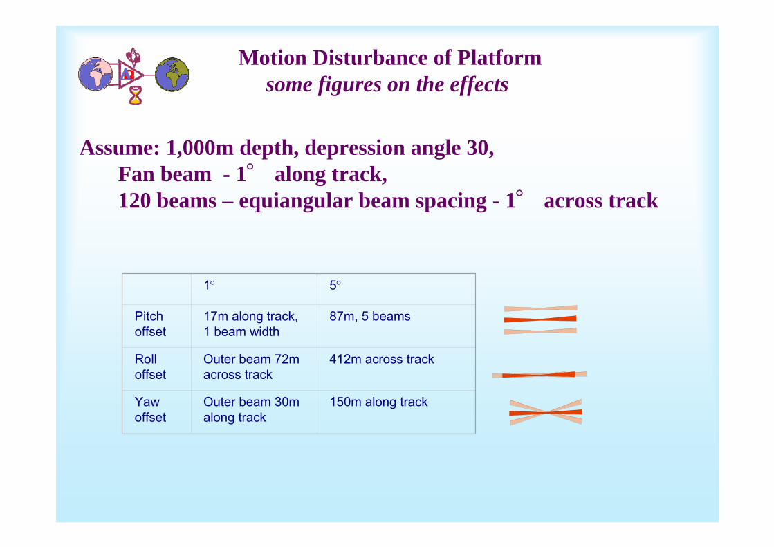
Motion Disturbance of Platformsome figures on the effects
Assume: 1,000m depth, depression angle 30, Fan beam - 1° along track, 120 beams – equiangular beam spacing - 1° across track
1° 5°
Pitch offset
17m along track, 1 beam width
87m, 5 beams
Rolloffset
Outer beam 72m across track
412m across track
Yawoffset
Outer beam 30m along track
150m along track

Variation in Sound Velocity Refraction

Sound Velocity
Error at 500m depth

Marine Survey Ship Mounted Multibeam
Dynamically positioned ship (DGPS)

Marine Survey ROV Mounted Multibeam
Higher resolution imagery – Lower positional accuracy, narrow swath.Wide area surveying and image mosaicking?
SBL/USBLtransponder
Dynamically positioned ship (DGPS)
Tethermanagement
system, depressoor weight
AUV
ROV

Position accuracy on sea surface GPS
Source Uncorrected With DifferentialIonosphere 0-30 meters Mostly RemovedTroposphere 0-30 meters All RemovedSignal Noise 0-10 meters All RemovedEphemeris 1-5 meters All RemovedClock Drift 0-1.5 m All RemovedMultipath 0-1 meters Not RemovedSA 0-70 meters All Removed
DGPS much higher level of accuracy than GPS, RTCM corrections.
Real Time Kinematic (RTK) GPS positional accuracies to ~ 10 – 20 cm. Roving receiver limited to within 10km radius of fixed receiver - in shore applications.
Networked RTK GPS for offshore use e.g. Fugro multiple fixed receivers with satellites can extend the range of rover GPS receiver. Sub meter accuracy possible.

Position error for sub sea:INS < 3m / hour drift bounded by 1% slant range USBL - (10 – 15m error at 1,000m depth)
Image resolution of 0.1m?
Position Accuracy Subsea
GAPS USBL – 1% Slant range
Fibre Gyro INS + Kalman FilterDoppler Velocity LogPrecision Depth
Motion Reference Unit
Nav sub systemsDGPS, Ship MRU, USBL(GAPS), INS, DVL, Precision Depth

Positional Accuracy / Resolution Trade Off.
High resolution multibeambathymetry/backscatter mappingROV mounted sonars.Reson 7125 Multibeam
0.1 - 1m seabed feature size typically distinguishable
Low resolution survey
High resolution surveyNarrow swath/field of view
Video mosaic mapping from ROV
Wide swath/field of view
Regional scale multibeam bathymetry/ backscatter mapping (National Seabed Survey)Hull mounted SonarsKongsberg-Simrad EM120, EM1002
0.01 - 0.1 m seabed feature size typically distinguishable
1 - 10m seabed feature size typically distinguishable
Ship mounted SonarsHigh accuracyLow resolution
ROV mounted SonarsLow accuracyHigh resolution

Systems Integration ROV, Ship, Sonar & INS
Mobile & Marine Robotics Research Centre University
ofLimerick

RV Celtic Explorer•GPS1•GAPS USBL
Navigation Equipment
ROV WetBottle
InterconnectWet Bottle
PHINSWet Bottle
RDIDVL Microbath
Precision Depth &Altimeter
SVP
UmbilicalTether
7LCU
7125 Sonar System
Fibre converter MUX
Rs232split DC
PSU
GPS2
Toolskid
Bathysaurus ROV•PHINS•Mobile GPS2•Depth sensor•DVL•USBL transponder
GPS1
GAPS

Technical challenges
GAPS – PHINS Interface (incompatible protocols)
•Send depth sensor data to GAPS
GAPS Holder
GAPS
Interface
GAPSPHINS
Depth sensor

Technical challenges
Depth sensor – PHINS Interface (incompatible protocols)
Depth(Microbath format)
PHINS
Depth sensor
Onboardmicrocontroller
Depth(PAROSCIENTIFIC format)
Hardware solution
Depth(Microbath format)
PHINS
Depth sensor
Softwareon mothership
Depth(PAROSCIENTIFIC format)
Software solution

Technical challenges
DVL (Real-time monitoring & Real-time change of mode of operation)
•Send corresponding configuration scripts during different stages of mission
Software on mothershipReal-time monitoring
Configuration scripts:Water track onlyBottom track onlyWater & Bottom track (combined)DVL
PHINS (Real-time monitoring & Real-time configuration)
•Electrical interface (communication parameters, protocols etc.)
•Mechanical interface (lever arms of sensors, geometric configuration etc.)
Software on mothershipReal-time monitoring
Real-time configuration
PHINS

Preparation
•Interconnection diagrams (two variants)
•Quick Reference Book (collection of key information from different manuals in compact form)
•MATLAB software to determine lever arms and make easy PHINS configuration
•LabView software for GAPS-PHINS-DEPTH interface
•DVL test trials in UL diving pool in order to test sign of DVL outputs

Interconnection Design

Problems during mobilisation / shakedown
Leak in the interconnection bottle•Cause: faulty connector•Responsibility: OceanTools (manufacturer)•Solution: Running repare of faulty connector
GAPS data were not always accepted by PHINS•Cause: wrong setting in GAPS software•Responsibility: IxSea engineer & confusing GAPS software•Solution: Set parameter D to correct value
BOSLevel
LevelSea
DropKeel
GAPS
Holder
SLz
BOSz
DKz
Hz
CGDistance Value Unit TypezSL 1.363 m VariablezBOS 7.262 m FixedzDK 3.000 m VariablezH 0.920 m FixedD = zSL+zBOS+zDK+zH = 12.545 m
Wrong operation of PHINS (instrument rotated by 180°inside enclosure & bugs in firmware)•Cause: error in technical drawing of enclosure•Responsibility: system integrator (RESON)•Solution: Rotation of PHINS and firmware update
Multibeam (7125) Integration. Day before embarking advised to swap sonar.•Cause: New product, DOA•Responsibility: (Reson)•Solution: Panic & swap to mature 8125

Results
•Successful integration GAPS-PHINS-DEPTH for the first time!
•Accurate determination of lever arms (all sensors were accepted by PHINS).
•High accuracy of navigation data.
•Succesful DVL real-time reconfiguration.
•Systematic approach for system integration.
•Discovery of errors in Bloom report.

Identified weak points
•Lack of leak detectors
•Inability to remotely switch on/off individual components
•Full separation between control and navigation
•Difficult navigation with existing displays in severe conditions

Simulation Solutions
Virtual Laboratory (A talk for another day)Modelling of pools, marine environment, vehicles (ship AUVs and
ROVs), navigation & payload sensors with signal level compatibility. Hardware in the loop testing and progressive porting of developed code
to the realtime target.Shift the load of integration and debugging to offline simulation rather
than during mobilisation with daily ship cost.
VR Command Centre for Offshore Ops(Augmented Reality) Video Clip
Real-Time High Resolution Imaging Sonar Simulator
Dr EdinOmerdic
Dr James Riordan

VR Command Centre for Offshore Ops
(Augmented Reality)
Lunar Module calling Heuston Control, Come in HeustonRoger niner, this is Heuston…
Features• Library of Vehicles (Ships, ROVs, AUVs)• Full dynamic models with signal-level compatibility• vR models integrated with real-time sensor input
- augmented reality during ops.• Configuration support tools for new vehicles.• Fault accommodation capabilities• Background seabed map import facility (INSS)• Models of waves, 3 D current models • and more.

VR Command Centre for Offshore Ops
(Augmented Reality)

Real-Time High Resolution Imaging Sonar Simulator
As discussed Imaging the Deep – Many issues affecting the quality of images, maps, 3D generated geometry model
Without draining the ocean it’s impossible to qualify?

Seafloor Terrain Synthesis ModelMulti-Fractal Surfaces – Hybrid Model
Combination of:Perlin noise
synthesisFourier synthesisWavelets
Permits local control over terrain features.
Multiple geologic features can be incorporated in a single terrain environment.
Fractal Dimension varying with altitude
Peaks and outcrops rough, valleys smooth – erosion and deposition
Low lying regions consist of sediment ripple beds – influence of currents

Acoustic Propagation ModelPath of acoustic pulse determined
by ray theory solution to Helmholtz Eq.
Seafloor Scattering Model
Output of Jacksons backscattering model for a typical seafloor configuration

View Dependant Refinementof Fractal Model of Seabed.
Full resolution terrain mesh viewed with adaptive refinement disabled
Multi-resolution representation of the terrain mesh, adaptive refinement enabled.

View Dependant Refinement
Full high-resolution mesh. The sonar position and fan beam footprint are represented by the superimposed
white sphere and blue wedge respectively.
Multi-resolution abstraction of the seafloor mesh. The geometric detail
within the fan beam footprint is preserved while non-contributing facets
are decimated to the maximum possible.

Incremental View Dependant Refinement
Detail information reserved for recovering Mi+1 from Mi.The structure queriedefficiently online duringsimulation to obtain adaptivemeshes on-the-fly byreconstructing the vertexdependency relations.Multiple sonar footprints can be accommodated.Real-time view dependant Level Of Detail
control of terrain mesh

Results – Multi Fractal SS Imagery

Results - Image Generation Performance
Based on Simulator Experimentation
• 4 -5 Hz ping rate while imaging seafloor terrain ~ 2 million facets.
• 40-fold increase in simulation throughput.
• Achieved principally by use of video rendering techniques within sonar simulation process.
• No degradation on integrity of imagery.
• Improved speed and quick results Simulation a more useful tool Allows user interaction on the fly as simulation progresses.
• Performance capability extended to survey scale maps.

Integration of Simulators
•Virtual Laboratory
•vR Command Centre for Offshore Ops
•Real-time High Resolution Imaging Simulator
•Work Underway

R.V. Celtic Explorer
Research Cruise CE0505 June 2005
First Irish-led deep water ROV habitat survey – technical and scientific partnership NUIG/UL
ROV multibeam and video surveys – high resolution mapping and non-destructive observations of habitat/fauna
Use INSS data to identify survey targets and plan surveys– essential data for cost effective survey
Bathysaurus ROV
HEA PRTLI 3 MSR3.2


Margaret Wilson, February 2006

ROV & INSS multibeam