Mobile Flash Butt Welding Systems - Al Burhan Group · Mobile Flash Butt Rail Welding Systems...
8
Mobile Flash Butt Welding Systems Mobile Flash Butt Welding Systems
Transcript of Mobile Flash Butt Welding Systems - Al Burhan Group · Mobile Flash Butt Rail Welding Systems...

Mobile Flash ButtWelding SystemsMobile Flash ButtWelding Systems

Reliability AndPerformance
Mobile Flash Butt RailWelding Systems
Mobile Flash Butt RailWelding Systems
Chemetron Railway Products, Inc. is a sub-sidiary of Progress Rail Services Corporation (aCaterpillar® company). Chemetron has beendesigning, manufacturing and operating railwelding equipment for over 50 years. Duringthat time, our weld systems have made over 25million welds and we provided welding equip-ment for use around the world. We own andoperate fixed plant and mobile welding equip-ment throughout North America. In addition,Chemetron-built welders are owned and operat-ed by many major railroads. At Chemetron, weare continually expanding our in-track weldingfleet to meet increased customer demand for ourwelders and services. Sixteen new machineswere manufactured in the last two years and allwere immediately put to work on NorthAmerican Class 1 railroads. Additional machinesare scheduled to be completed in 2009.
Chemetron is very excited to announce theaddition of a multi-purpose welding head to ourin-track fleet. Following the development of theworld’s first DC power for in-track welders in ourCHEM 110 machines, we designed a 180-ton in-track welding head that is capable of makingclosure welds up to a 10-inch gap without a sep-arate puller unit. Now both of these weld sys-tems are available to the global market. The DCweld heads allow for greater efficiency of thegenerator thus allowing a smaller generatorwith more welding current than competitive ACmachines.
Reliability AndPerformance
Our mobile welders are designed to equal orexceed the quality and reliability of fixed plantwelds. Our mobile welder combines the indus-try’s most advanced welding technology with thereliability and consistency that Chemetrondesigns into all its welding systems. In additionto improved productivity and quicker setup, ourpatented software automatically detects if therails are properly positioned and applies theproper hold times for a closure weld. If no stretchis detected, our normal electric flash weldparameters are applied. All of Chemetron’swelding systems also contain complete self-diagnostic software to allow for easy mainte-nance and repairs. Chemetron welding systemscan be accessed via cellular modem in the eventtechnical assistance is needed from our U.S.headquarters. All of the systems are designedfor extreme hostile environments with protectionfrom shock, vibration, temperature, and humid-ity built-in. Performance and reliability of thesystems are designed to emulate fixed plantmachines. The maintenance procedures adhereto MTBF schedules. Every unit has complete self-diagnostic systems built-in that operatedthrough user friendly displays. Spare compo-nents are commonly available and easilyaccessed throughout the world.
General Description
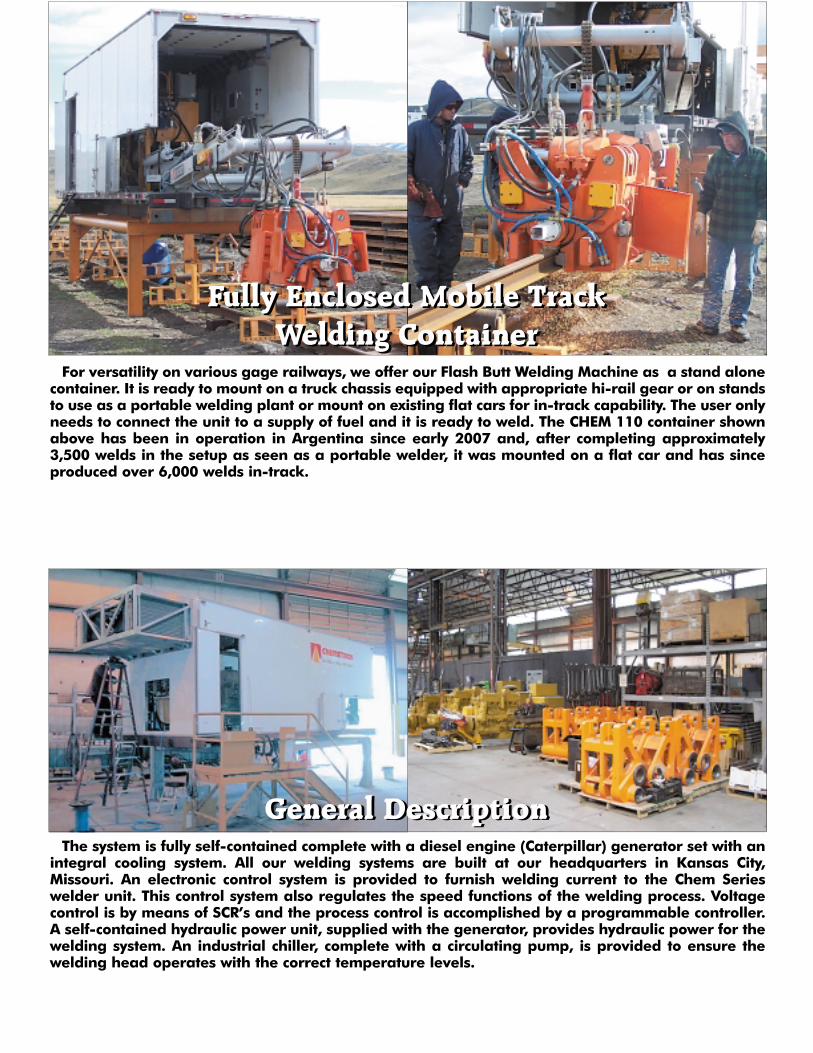
Fully Enclosed Mobile Track Welding Container
For versatility on various gage railways, we offer our Flash Butt Welding Machine as a stand alonecontainer. It is ready to mount on a truck chassis equipped with appropriate hi-rail gear or on standsto use as a portable welding plant or mount on existing flat cars for in-track capability. The user onlyneeds to connect the unit to a supply of fuel and it is ready to weld. The CHEM 110 container shownabove has been in operation in Argentina since early 2007 and, after completing approximately3,500 welds in the setup as seen as a portable welder, it was mounted on a flat car and has sinceproduced over 6,000 welds in-track.
Fully Enclosed Mobile Track Welding Container
The system is fully self-contained complete with a diesel engine (Caterpillar) generator set with anintegral cooling system. All our welding systems are built at our headquarters in Kansas City,Missouri. An electronic control system is provided to furnish welding current to the Chem Serieswelder unit. This control system also regulates the speed functions of the welding process. Voltagecontrol is by means of SCR’s and the process control is accomplished by a programmable controller.A self-contained hydraulic power unit, supplied with the generator, provides hydraulic power for thewelding system. An industrial chiller, complete with a circulating pump, is provided to ensure thewelding head operates with the correct temperature levels.
General Description
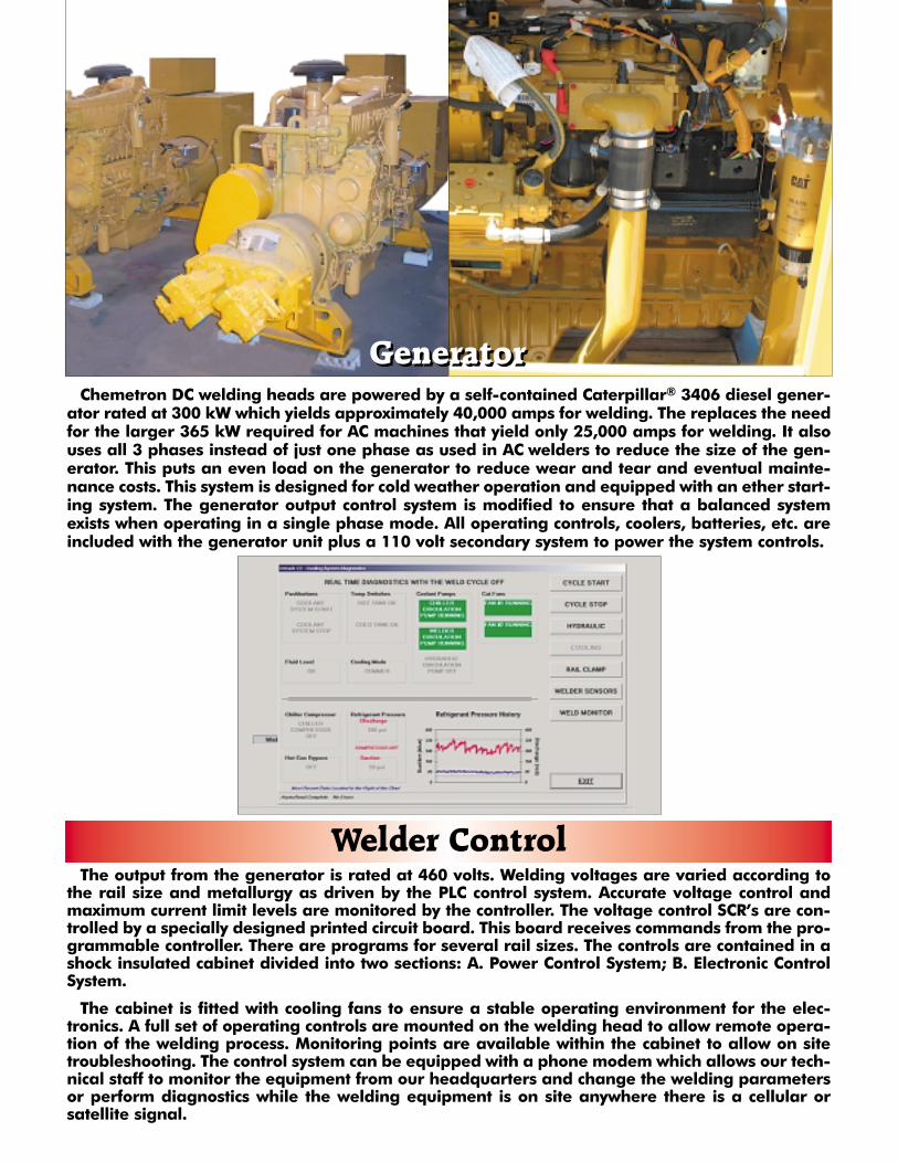
GeneratorChemetron DC welding heads are powered by a self-contained Caterpillar® 3406 diesel gener-
ator rated at 300 kW which yields approximately 40,000 amps for welding. The replaces the needfor the larger 365 kW required for AC machines that yield only 25,000 amps for welding. It alsouses all 3 phases instead of just one phase as used in AC welders to reduce the size of the gen-erator. This puts an even load on the generator to reduce wear and tear and eventual mainte-nance costs. This system is designed for cold weather operation and equipped with an ether start-ing system. The generator output control system is modified to ensure that a balanced systemexists when operating in a single phase mode. All operating controls, coolers, batteries, etc. areincluded with the generator unit plus a 110 volt secondary system to power the system controls.
Generator
The output from the generator is rated at 460 volts. Welding voltages are varied according tothe rail size and metallurgy as driven by the PLC control system. Accurate voltage control andmaximum current limit levels are monitored by the controller. The voltage control SCR’s are con-trolled by a specially designed printed circuit board. This board receives commands from the pro-grammable controller. There are programs for several rail sizes. The controls are contained in ashock insulated cabinet divided into two sections: A. Power Control System; B. Electronic ControlSystem.
The cabinet is fitted with cooling fans to ensure a stable operating environment for the elec-tronics. A full set of operating controls are mounted on the welding head to allow remote opera-tion of the welding process. Monitoring points are available within the cabinet to allow on sitetroubleshooting. The control system can be equipped with a phone modem which allows our tech-nical staff to monitor the equipment from our headquarters and change the welding parametersor perform diagnostics while the welding equipment is on site anywhere there is a cellular orsatellite signal.
Welder Control

System ControlThe integrated control system of using a linear transducer in conjunction with a flow control sys-
tem and programmable controller ensures that a minimum of operating components arerequired to perform a weld sequence. All field changes for various rail sizes are accomplished byprogram selection - there are NO weld cycle overrides available to the operator. All welds meetor exceed the AREMA specifications for flash butt welding of rails.
Rail Hardness Test Sample Bend Block Modulus Of DeflectionMinimum Length Spacing Rupture (min.) Minimum248 BHN 6’0”/1.829m 48”/1.219m 100,000 psi 1.5”/38.1mm300 BHN 6’0”/1.829m 48”/1.219m 120,000 psi 1.0”/25.4mm341 BHN 6’0”/1.829m 48”/1.219m 125,000 psi .75”/19.05mm
Weld DataThe PLC continually monitors the weld process. A printout of all weld parameters is provided at
the end of each weld cycle and is correlated to the exact weld by custom annotation. Any param-eter which exceeds either a customer determined quality guideline or AREMA guidelines is auto-matically highlighted on the weld print out.
HydraulicsPressure-compensated engine-driven double pumps provide power for the welder and crane.
All control functions are by means of solenoid actuated valves. The pumps and valves used ensureprompt response to program commands. Welding speed is controlled by high precision propor-tional flow controls which ensure very accurate welding speeds. A linear transducer ensuresrepeatability of the flow settings within the program changes.The hydraulic system is self-con-tained and features an external cooling system for stable operating temperatures. High and lowpressure return filters are used in the system for reliable operation.
ChillerAn electrically driven chiller unit is provided to control the welding head operating temperatures
within preset limits. Chiller operation is automatic and has adjustable temperature settings.
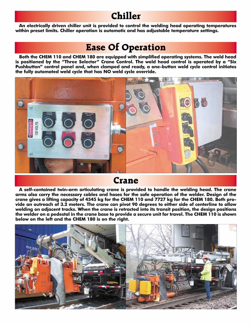
Ease Of OperationBoth the CHEM 110 and CHEM 180 are equipped with simplified operating systems. The weld head
is positioned by the “Three Selector” Crane Control. The weld head control is operated by a “SixPushbutton” control panel and, when clamped and ready, a one-button weld cycle control initiatesthe fully automated weld cycle that has NO weld cycle override.
CraneA self-contained twin-arm articulating crane is provided to handle the welding head. The crane
arms also carry the necessary cables and hoses for the safe operation of the welder. Design of thecrane gives a lifting capacity of 4545 kg for the CHEM 110 and 7727 kg for the CHEM 180. Both pro-vide an outreach of 3.2 meters. The crane can pivot 90 degrees to either side of centerline to allowwelding on adjacent tracks. When the crane is retracted into its transit position, the design positionsthe welder on a pedestal in the crane base to provide a secure unit for travel. The CHEM 110 is shownbelow on the left and the CHEM 180 is on the right.

Welding Heads
CHEM 180CHEM 110
Welding HeadsBoth the CHEM 110 and the CHEM 180 series machines are designed to weld rails up to 10,000
square millimeters in cross section by the continuous flash butt process. Typical weld cycles of 180 sec-onds allow in-track welding productivity of 8 to 10 welds per hour. Integral with the welding head isa device to automatically remove the welder flash material. Construction of the welding head is suchthat the two halves of the machine pivot and traverse along a central shaft. The pivot action is pow-ered by upper lateral hydraulic cylinders to clamp the rails. Traversing is accomplished by means oftwo hydraulically inter-connected cylinders. One half of the head contains the specially wound trans-formers. Transfer of welding current and voltage from the transformer side to the other side is viaspecially designed shafts in the hydraulic cylinders. Four copper alloy electrode inserts and four mildsteel clamp pad inserts provide contact with the rail web. Adjustments are available within the sys-tem to ensure proper alignment. A linear transducer is mounted within the welder central shaft andis used to monitor the weld process as well as control the weld speed and position. Output from thedevice is fed to a programmable logic controller. A system of internal passages ensures that the cool-ing medium flows continuously through the transformers, welding electrodes, and cylinder shafts.Design of the hydraulic system includes a circulating system to allow rapid warm up of the systemduring cold weather or for a quick start situation. The head is suspended from its carrier by an insu-lated adjustable connector.
CHEM 110 CHEM 180
Contact InformationFor additional information, visit our web site at www.progressrail.com. To learn more about how
Progress Rail Services can provide your company with the best flash butt welding solutions available,contact Richard Frostman at [email protected] or by phone at 859-291-5466 or MarkMcLean at [email protected] or by phone at 719-577-9184.
5600 StillwellKansas City, MO 64120
Telephone (816) 241-1683Fax (816) 241-0677
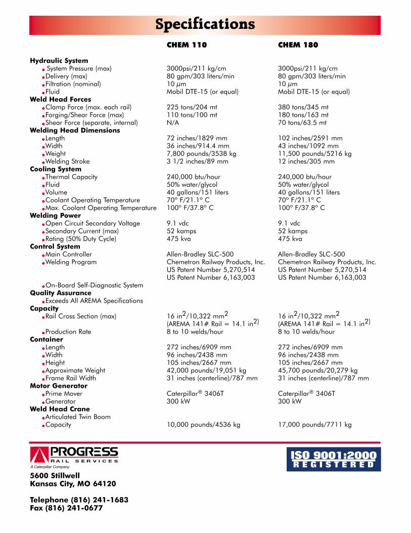
SpecificationsCHEM 110 CHEM 180
Hydraulic System� System Pressure (max) 3000psi/211 kg/cm 3000psi/211 kg/cm� Delivery (max) 80 gpm/303 liters/min 80 gpm/303 liters/min� Filtration (nominal) 10 µm 10 µm� Fluid Mobil DTE-15 (or equal) Mobil DTE-15 (or equal)
Weld Head Forces� Clamp Force (max. each rail) 225 tons/204 mt 380 tons/345 mt� Forging/Shear Force (max) 110 tons/100 mt 180 tons/163 mt� Shear Force (separate, internal) N/A 70 tons/63.5 mt
Welding Head Dimensions� Length 72 inches/1829 mm 102 inches/2591 mm� Width 36 inches/914.4 mm 43 inches/1092 mm� Weight 7,800 pounds/3538 kg 11,500 pounds/5216 kg� Welding Stroke 3 1/2 inches/89 mm 12 inches/305 mm
Cooling System� Thermal Capacity 240,000 btu/hour 240,000 btu/hour� Fluid 50% water/glycol 50% water/glycol� Volume 40 gallons/151 liters 40 gallons/151 liters� Coolant Operating Temperature 70º F/21.1º C 70º F/21.1º C� Max. Coolant Operating Temperature 100º F/37.8º C 100º F/37.8º C
Welding Power� Open Circuit Secondary Voltage 9.1 vdc 9.1 vdc� Secondary Current (max) 52 kamps 52 kamps� Rating (50% Duty Cycle) 475 kva 475 kva
Control System� Main Controller Allen-Bradley SLC-500 Allen-Bradley SLC-500� Welding Program Chemetron Railway Products, Inc. Chemetron Railway Products, Inc.
US Patent Number 5,270,514 US Patent Number 5,270,514US Patent Number 6,163,003 US Patent Number 6,163,003
� On-Board Self-Diagnostic SystemQuality Assurance
� Exceeds All AREMA SpecificationsCapacity
� Rail Cross Section (max) 16 in2/10,322 mm2 16 in2/10,322 mm2
(AREMA 141# Rail = 14.1 in2) (AREMA 141# Rail = 14.1 in2)
� Production Rate 8 to 10 welds/hour 8 to 10 welds/hourContainer
� Length 272 inches/6909 mm 272 inches/6909 mm� Width 96 inches/2438 mm 96 inches/2438 mm� Height 105 inches/2667 mm 105 inches/2667 mm� Approximate Weight 42,000 pounds/19,051 kg 45,700 pounds/20,279 kg� Frame Rail Width 31 inches (centerline)/787 mm 31 inches (centerline)/787 mm
Motor Generator� Prime Mover Caterpillar® 3406T Caterpillar® 3406T� Generator 300 kW 300 kW
Weld Head Crane� Articulated Twin Boom� Capacity 10,000 pounds/4536 kg 17,000 pounds/7711 kg