Mobile Environmental Monitoring Platform Manual.pdf · Maintenance procedures and calibration...
21
Government of Newfoundland & Labrador Department of Environment and Conservation Water Resources Management Division St. John’s, NL, A1B 4J6 Canada Mobile Environmental Monitoring Platform Principles of Operation
Transcript of Mobile Environmental Monitoring Platform Manual.pdf · Maintenance procedures and calibration...

Government of Newfoundland & Labrador Department of Environment and Conservation
Water Resources Management Division St. John’s, NL, A1B 4J6 Canada
Mobile Environmental Monitoring Platform
Principles of Operation


Table of ContentsTable of ContentsTable of ContentsTable of Contents
Foreword -------------------------------------------------------------------------------------------------------------------------------------------------------------------- 1
Introduction ---------------------------------------------------------------------------------------------------------------------------------------------------------------- 1
MEMP Components ------------------------------------------------------------------------------------------------------------------------------------------------------ 1
Trailer Details and Running Gear ---------------------------------------------------------------------------------------------------------------------------------- 1
Climate Monitoring Sensors ---------------------------------------------------------------------------------------------------------------------------------------- 1
Water Quality Monitoring Equipment --------------------------------------------------------------------------------------------------------------------------- 3
Water Quantity Monitoring Equipment ------------------------------------------------------------------------------------------------------------------------- 4
Additional Electronics ------------------------------------------------------------------------------------------------------------------------------------------------ 4
Power Supply ----------------------------------------------------------------------------------------------------------------------------------------------------------- 5
General Usage Instructions -------------------------------------------------------------------------------------------------------------------------------------------- 5
Site Selection ------------------------------------------------------------------------------------------------------------------------------------------------------------ 5
Deployment ------------------------------------------------------------------------------------------------------------------------------------------------------------- 6
Mast Setup -------------------------------------------------------------------------------------------------------------------------------------------------------------- 6
Datalogger Operation --------------------------------------------------------------------------------------------------------------------------------------------------- 7
Main Scan Sequence -------------------------------------------------------------------------------------------------------------------------------------------------- 7
Slow Scan Sequence--------------------------------------------------------------------------------------------------------------------------------------------------- 8
Program Flags ---------------------------------------------------------------------------------------------------------------------------------------------------------- 8
Parameter Alarm Values and Autosampling ------------------------------------------------------------------------------------------------------------------- 9
Summary ------------------------------------------------------------------------------------------------------------------------------------------------------------------ 10
Appendix I. Documents and Manuals ------------------------------------------------------------------------------------------------------------------------- 11
Electric Braking Unit ------------------------------------------------------------------------------------------------------------------------------------------------ 11
Electronic Documents ---------------------------------------------------------------------------------------------------------------------------------------------- 12
Spill Contingency Plan ---------------------------------------------------------------------------------------------------------------------------------------------- 13
Appendix II. CRBasic Program -------------------------------------------------------------------------------------------------------------------------------- 14
Appendix III. Important Login Information ---------------------------------------------------------------------------------------------------------------- 16
Login Information --------------------------------------------------------------------------------------------------------------------------------------------------- 16
MEMP LAN Information ------------------------------------------------------------------------------------------------------------------------------------------- 16
Appendix IV. Wiring Diagrams--------------------------------------------------------------------------------------------------------------------------------- 17
CR1000 wiring panel as of October, 2014. -------------------------------------------------------------------------------------------------------------------- 17
Thermo King MD-100 Reefer Unit Relay Wiring ------------------------------------------------------------------------------------------------------------- 18

Mobile Environmental Monitoring Platform – Principles of Operation
1111
ForewordForewordForewordForeword
The Mobile Environmental Monitoring Platform (MEMP) is intended for rapid-response observation of water quality, water quantity, and climate events. The MEMP is outfitted with a series of instruments capable of monitoring numerous parameters and automatically withdrawing a grab sample based on user-set thresholds.
This manual aims to outline the major features of the MEMP and required maintenance.
IntroductionIntroductionIntroductionIntroduction
In total five MEMPs were designed and built by Grantec Engineering in Nova Scotia using concept sketches from Environment Canada. Four MEMPs are located in the Maritimes while one unit is dedicated to Newfoundland and Labrador for emergency monitoring of spills and shorter term seasonal monitoring.
To ensure that the MEMP is always available in case of urgent need, every endeavor should be made to maintain the trailer in good condition; including water quality/quantity and climate monitoring equipment, datalogger, telemetry, power supply, and running gear.
MEMP ComponentsMEMP ComponentsMEMP ComponentsMEMP Components
Trailer Details and Running GearTrailer Details and Running GearTrailer Details and Running GearTrailer Details and Running Gear
The MEMP is housed in a custom-built 17’ x 6’ twin axle trailer, intended to be towed by a pickup truck with at least 5000 lbs. in towing capacity and outfitted with a Class III hitch.
Those responsible for towing the MEMP must be competent in maneuvering trailers and be cognizant of the height and side clearances necessary while under way. Training opportunities should be sought if the operator is not confident in their abilities – especially since maneuvering the MEMP into confined areas while on rough roads is the norm.
Due to the MEMP’s weight and size, it is outfitted with a Tekonsha Voyager 9030 inertia–activated proportional braking system. When hitching the pickup to the MEMP, drivers should ensure that the braking unit connection is made and the device is calibrated to the current weight of the trailer and road conditions. Complete instructions can be found in Appendix I.
Prior to hitching the trailer and truck, it is important to inspect the critical components of the trailer. Ensure tire pressures are sufficient (see tire sidewall specifications), the hitch receiver is firmly mounted to the trailer, the emergency brake battery is fully charged and in good condition, and loose materials inside the trailer are secured. After hitching the trailer and making all connections (ball firmly socketed into receiver, emergency brake cable attached to the truck, and electrical connection), ensure all running lights are operational. Also, ensure that a spare tire is available in the MEMP in case of a flat tire or blowout while on the road.
Climate Monitoring SensorsClimate Monitoring SensorsClimate Monitoring SensorsClimate Monitoring Sensors
Climate sensors are affixed to the aluminum mast at about 20’ above the ground. When positioning the MEMP, thought should be made regarding the orientation of the mast, as it is a square pole which will limit orientation of mast-mounted equipment once affixed with bolts. Ideally, sensors should be located in as open a space as
Figure 1: MEMP running gear

Mobile Environmental Monitoring Platform – Principles of Operation
2222
practical to reduce undue influence of obstructions, such as buildings and trees. Since the mast is affixed to the MEMP itself, level and open space should be chosen for deployment.
Maintenance procedures and calibration intervals should be followed according to Protocol Manual for the
Operation and Maintenance of Campbell Scientific Canada Corp. Quick Deploy Weather Systems (Campbell Scientific Canada, 2012. See Appendix I).
Table 1: Mast-mounted sensors and equipment
Temperature/Relative Humidity (HC-S3)
The HygroClip by Rotronic Instrument Corporation temperature and relative humidity probe has a humidity accuracy of +/- 1.5% at 23oC and a temperature accuracy of +/- 0.2oC from -30oC to 60oC. The sensor is protected by a radiation shield to reduce the impact of direct sunlight on readings. Performance should be evaluated on an annual basis.
Figure 2: Temp/RH outfitted with
Model 41003-X radiation shield
Tipping-bucket rain gauge (TE525M)
This metric tipping bucket rain gauge manufactured by Texas Electronics measures precipitation to an accuracy of 0.1 mm with each tip. The bucket is outfitted with a magnetic reed switch which closes a circuit each time the bucket falls – each closure represents accumulation of 0.1 mm. For optimum performance, the bucket should be as close to level as possible. A level bubble can be found inside the gauge; however, its location at the top of the mast during deployment will preclude its use. To level the sensor, it is best to ensure the MEMP itself is as level as possible. Accuracy of the gauge should be checked annually and calibrated if required.
Figure 3: TE525M Tipping Bucket
Rain Gauge
Anemometer (05103-10)
The wind speed and direction monitor is manufactured by R. M. Young. Wind speed is considered accurate to 1% (0.3 m/s) from 0 to 100 m/s. Wind direction is accurate to +/- 3o. Proper wind direction measurement relies on proper orientation of the sensor - when deploying the anemometer, ensure that the small black plastic junction box points due south. Nose cone and vertical bearings should be checked annually and replaced if necessary.
Figure 4: 05103-10 R. M. Young
Anemometer
Other Equipment
In addition to the climate sensors, the mast head is fitted with a webcam (CC5MPX) and a Yagi (directional) cell antenna for the Raven X Cell Modem/Gateway. The webcam has adjustments for pan, zoom, tilt, zoom and focus that must be adjusted upon fixing the mast in place. The cell phone antenna, if cellular telemetry is to be used, should be aimed directly at a cell tower with optimum line-of-sight.

Mobile Environmental Monitoring Platform – Principles of Operation
3333
CC5MPX Web Camera The CC5MPX web camera from Campbell Scientific allows for the timed or triggered acquisition of high definition imagery or video. The camera leaves standby mode upon receipt of a trigger from the datalogger, acquires an image, and transfers the file to the datalogger or remote FTP server.
Figure 5: CC5MPX web cam
Raven X Modem/Gateway
The gateway provides an interface between the Internet and the MEMP’s Local Area Network (LAN) allowing high-speed access to data, imagery, and programming. Since cellular signals may be weak in remote locations, a directional Yagi antenna boosts the signal within a narrow line-of-sight of a 3G enabled cellular tower.
Figure 6: Wilson 10 dBi Yagi
Cellular Antenna
Water Quality Monitoring EquipmentWater Quality Monitoring EquipmentWater Quality Monitoring EquipmentWater Quality Monitoring Equipment
Datasonde 5X
The MEMP is outfitted with a Hydrolab Datasonde (DS5) multi-parameter probe that measures temperature, pH, specific conductivity, Total Dissolved Solids (TDS), dissolved oxygen (DO), and turbidity. The Hydrolab is deployed in the nearby water body using a 50 m cable to provide flexibility in deployment methods and MEMP placement. Care should be taken to avoid damaging the cable while deployed – protective conduit is recommended. Additionally, the Hydrolab should be deployed in a protective casing to prevent damage to the instrument from vigorous flow and streambed movement. For extra security, a wire rope should be connected from the instrument casing to a fixed shoreline structure such as a stout tree or rebar driven into the ground.
Maintenance of the DS5 is performed according to Hydrolab DS5, DS5, and MS5 Water Quality Multiprobes (Hach Company, 2006. See Appendix I) and calibration should be performed according to Protocols Manual
for RTWQ Monitoring in NL (Environment and Conservation, 2013. See Appendix I).
Table 2: Hydrolab DS5 sensors
Water Temperature (Not pictured)
Range: -5oC to 50 oC Accuracy: +/- 0.10 oC
Figure 7: Hydrolab Datasonde
pH
Range: 0 to 14 Accuracy: +/- 0.2
Conductivity Range: 0 mS/cm to 100 mS/cm Accuracy: +/- 0.001 mS/cm
Luminescent Dissolved Oxygen (LDO)
Range: 0 mg/l to 30 mg/l Accuracy: +/- 0.01 mg/l for 0 to 8 mg/l; +/- 0.02 mg/l for > 8 mg/l
Turbidity
Range: 0 NTU to 3000 NTU Accuracy: +/- 1% from 0 NTU to 100 NTU, +/- 3% from 100 NTU to 400 NTU, +/- 5% from 400 NTU to 3000 NTU.
pH Reference pH Glass bulb
LDO Sensor
Conductivity Sensor
Turbidity Sensor
Mobile Environmental Monitoring Platform – Principles of Operation
4444
Water Quantity Monitoring EquipmentWater Quantity Monitoring EquipmentWater Quantity Monitoring EquipmentWater Quantity Monitoring Equipment
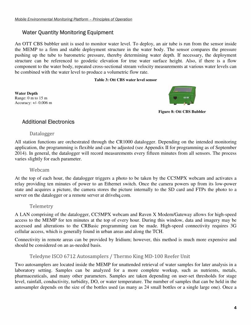
An OTT CBS bubbler unit is used to monitor water level. To deploy, an air tube is run from the sensor inside the MEMP to a firm and stable deployment structure in the water body. The sensor compares the pressure pushing up the tube to barometric pressure, thereby determining water depth. If necessary, the deployment structure can be referenced to geodetic elevation for true water surface height. Also, if there is a flow component to the water body, repeated cross-sectional stream velocity measurements at various water levels can be combined with the water level to produce a volumetric flow rate.
Table 3: Ott CBS water level sensor
Water Depth
Range: 0 m to 15 m Accuracy: +/- 0.006 m
Figure 8: Ott CBS Bubbler
Additional ElectronicsAdditional ElectronicsAdditional ElectronicsAdditional Electronics
Datalogger
All station functions are orchestrated through the CR1000 datalogger. Depending on the intended monitoring application, the programming is flexible and can be adjusted (see Appendix II for programming as of September 2014). In general, the datalogger will record measurements every fifteen minutes from all sensors. The process varies slightly for each parameter.
Webcam
At the top of each hour, the datalogger triggers a photo to be taken by the CC5MPX webcam and activates a relay providing ten minutes of power to an Ethernet switch. Once the camera powers up from its low-power state and acquires a picture, the camera stores the picture internally to the SD card and FTPs the photo to a server on the datalogger or a remote server at drivehq.com.
Telemetry
A LAN comprising of the datalogger, CC5MPX webcam and Raven X Modem/Gateway allows for high-speed access to the MEMP for ten minutes at the top of every hour. During this window, data and imagery may be accessed and alterations to the CRBasic programming can be made. High-speed connectivity requires 3G cellular access, which is generally found in urban areas and along the TCH.
Connectivity in remote areas can be provided by Iridium; however, this method is much more expensive and should be considered on an as-needed basis.
Teledyne ISCO 6712 Autosamplers / Thermo King MD-100 Reefer Unit
Two autosamplers are located inside the MEMP for unattended retrieval of water samples for later analysis in a laboratory setting. Samples can be analyzed for a more complete workup, such as nutrients, metals, pharmaceuticals, and many other parameters. Samples are taken depending on user-set thresholds for stage level, rainfall, conductivity, turbidity, DO, or water temperature. The number of samples that can be held in the autosampler depends on the size of the bottles used (as many as 24 small bottles or a single large one). Once a

Mobile Environmental Monitoring Platform – Principles of Operation
5555
sample has been taken by the autosampler, an email is sent to Environment and Conservation staff requesting a sample pick up.
As the autosamplers are triggered, the Thermoking MD-100 reefer unit is activated to maintain the air temperature inside the MEMP between 3 – 5oC to avoid degradation of water chemistry. The reefer unit is a diesel-powered and capable of heating or cooling, depending on ambient conditions.
Figure 9: Teledyne ISCO 6712
Figure 10: MEMP side profile, showing MD-100
Power SupplyPower SupplyPower SupplyPower Supply
The power supply in the MEMP is divided into two main circuits: the Equipment Circuit and the Reefer Circuit. The Equipment Circuit is intended to power the datalogger, telemetry, sensors, and sampling pumps. The second circuit is the Reefer Circuit which is responsible for starting the reefer unit.
Equipment Circuit
The Equipment Circuit consists of a pair of 12V, 100 Ah, deep cycle batteries wired together in parallel to maintain voltage but double capacity. These batteries provide power to the CR1000 datalogger, water samplers, sensors, and telemetry equipment and are charged by a 30W solar panel via a SunSaver 6 charge/regulator.
A sub-circuit, powering a cellular modem and Ethernet switch is controlled by the CR1000 datalogger via a relay for ten minutes at the top of each hour.
Reefer Circuit
The reefer unit consists of two 12V heavy-duty truck starter batteries wired in series to boost the starting voltage. The batteries are maintained by the alternator in the engine of the reefer unit.
General Usage InstructionsGeneral Usage InstructionsGeneral Usage InstructionsGeneral Usage Instructions
Site SelectionSite SelectionSite SelectionSite Selection
In general, the deployment location of the MEMP should follow the Site Selection principles outlined in Protocols Manual for RTWQ Monitoring in NL (Environment and Conservation, 2013. See Appendix I).
The choice of a deployment location often balances the MEMP’s ability to monitor optimum water quality, quantity, and climate data. It is likely that no particular location will allow ideal monitoring of all three data types. Consideration of the deployment objective is critical.

Mobile Environmental Monitoring Platform – Principles of Operation
6666
DeploymentDeploymentDeploymentDeployment
The MEMP should be deployed in as level an area as possible to ensure the mast is vertical, since the mast is fixed in relation to the trailer orientation. In some circumstances, the land may need to be altered to provide a suitable level spot or to allow access in difficult terrain.
When maneuvering the trailer to its deployment location, it is often wise to place wooden boards beneath the tires to avoid them sinking into soft soil over the course of the deployment. In cases where terrain is uneven, additional boards on one side or the other may be useful in levelling the MEMP. To un-hitch the trailer, place wheel chocks to steady the trailer, release the tongue clasp and lower the trailer stand such that it raises the tongue off the ball (consider using another board to avoid the stand sinking into soft ground). The truck can then be moved to a more convenient location.
To prevent dangerous “see-sawing” of the MEMP during use, axel stands must be placed under the door sill. Raise the trailer stand to pivot the rear of the trailer upwards. Adjust the height of the axel stands and place them evenly under the rear sill of the MEMP. Lower the trailer stand to seat the trailer on the axel stands.
Mast SetupMast SetupMast SetupMast Setup
During setup, the mast head fitted with sensors and equipment is socketed into the square aluminum mast and affixed with three bolts passing perpendicularly through both the mast head and mast. This step is best done while the mast is at ground level, taking care not to bump sensitive equipment on the ground. Once the mast head is mounted, with two or more people, place the mast vertical, next to the receptacle/bracket on the front right of the trailer. With one person standing or sitting on the lower front ledge of the MEMP, hoist the mast vertically and guide into the top of the receptacle/bracket. Align the three holes on the mast with the corresponding holes on the receptacle/bracket and secure with bolts.
A 30 watt solar panel is affixed to the mast below the mast head fixture. Two pins are used to secure the solar panel to the mast.
Figure 11: MEMP showing full mast setup
Figure 12: Mast socket

Mobile Environmental Monitoring Platform – Principles of Operation
7777
Datalogger OperationDatalogger OperationDatalogger OperationDatalogger Operation
All MEMP functions are routed and controlled via the datalogger using CRBasic code (see manual referenced in Appendix I). The programming can be conceptualized as a loop (or series of loops) called a scan that occurs on a defined interval. Within the scan is a sequence of events such as reading a sensor, setting a control port to high/low voltage, or recording data to a table. Table 1 outlines critical Main Scan events that take place within the CRBasic programming.
Main Scan SequenceMain Scan SequenceMain Scan SequenceMain Scan Sequence
In the current configuration, the datalogger makes a scan of the meteorological sensors every fifteen seconds and holds the data in a buffer. Every fifteen minutes, buffered meteorological data is averaged and summed, water quality and quantity data is sampled, and all results saved to the data table (see Table 1 for details).
Table 4: Outline of Main Scan Sequence
Interval (hh:mm:ss) Activity
00:00:05 Store in buffer
• Air Temperature (oC) • Relative Humidity (%) • Wind Speed (km/h) • Wind Direction (o) • Precipitation (mm)
00:15:00 Store in buffer • Water Temperature (oC) • pH (units) • Specific Conductivity (uS/cm) • TDS (g/l) • DO (% saturation) • DO (mg/l) • Turbidity (NTU) • Stage (m)
00:15:00 Write to DataTable
• Average Air Temperature (oC) • Average Relative Humidity (%) • Average Wind Speed (km/h) • Average Wind Direction (o) • Gust Speed (km/h) • Gust Direction (o) • Total Precipitation (mm) • Average Water Temperature (oC) • Average pH (units) • Average Specific Conductivity (uS/cm) • Average TDS (g/l) • Average DO (% saturation) • Average DO (mg/l) • Average Turbidity (NTU) • Average Stage (m)
01:00:00 Trigger Webcam Picture
01:00:00 – 01:10:00 Close Relay • Power Cell Modem • Power Ethernet Switch
Upon Exceeding Trigger Value Activate reefer unit
Activate grab sampler

Mobile Environmental Monitoring Platform – Principles of Operation
8888
Slow Scan SequenceSlow Scan SequenceSlow Scan SequenceSlow Scan Sequence
Outside of the Main Sequence, an additional loop is run where an email alert is sent notifying of a sample available for pickup. The email is sent via the Google Gmail SMTP server (see Appendix III for SMTP credentials).
Figure 13: Example email from MEMP
Program FlagsProgram FlagsProgram FlagsProgram Flags
A series of flags or switches are available to the user to control the operation of the datalogger without altering the CRBasic program. The flags can be manipulated when connected to the MEMP via LoggerNet. The flags are described below.
CC5MPX_Trigger_Flag: Setting this flag to true will cause the webcam to take a picture at the top of each hour.
Sample_Trigger: With auto-samplers in standby mode, setting this flag to true will cause the auto-samplers to begin withdrawing a sample of water from the water body, regardless of Alarm Values (see next section for setting Alarm Values).
Reefer_on_Flag: When the reefer unit is in standby mode, activating this flag will cause the unit to run and begin controlling the interior temperature of the MEMP.
Mobile Environmental Monitoring Platform – Principles of Operation
9999
Reefer_off_Flag: When the reefer unit is running, activating this flag will cause the unit to turn off and remain in standby mode.
Email_Send_Flag: With this value set to true, an email will be sent alerting the user that samples are available for pickup from the MEMP. Emails addresses must be changed via CRBasic.
Parameter Alarm Values and Parameter Alarm Values and Parameter Alarm Values and Parameter Alarm Values and AutosamplingAutosamplingAutosamplingAutosampling
Several of the parameters monitored by the MEMP (temperature, pH, conductivity, dissolved oxygen, turbidity, stage level, precipitation) can have thresholds assigned to them whereby the datalogger counts the number of threshold transgressions.
To set alarm values, open Notepad in Windows and input the desired values in the following order, separated by commas (with no spaces): temperature, pH, conductivity, DO, turbidity, stage, and hourly rainfall rain.
Save with the filename config.txt. When connected to the datalogger via Loggernet, upload the file to the Usr drive and activate the flag Text_read_flag. This will set the alarm values into the program.
With alarm values set, ensure that the desired parameter Check_Flag is activated. With alarm values and any relevant parameter Check_Flag activated, the datalogger will cause a grab sample to be taken and the reefer unit activated to keep the trailer interior cool for sample-holding purposes.
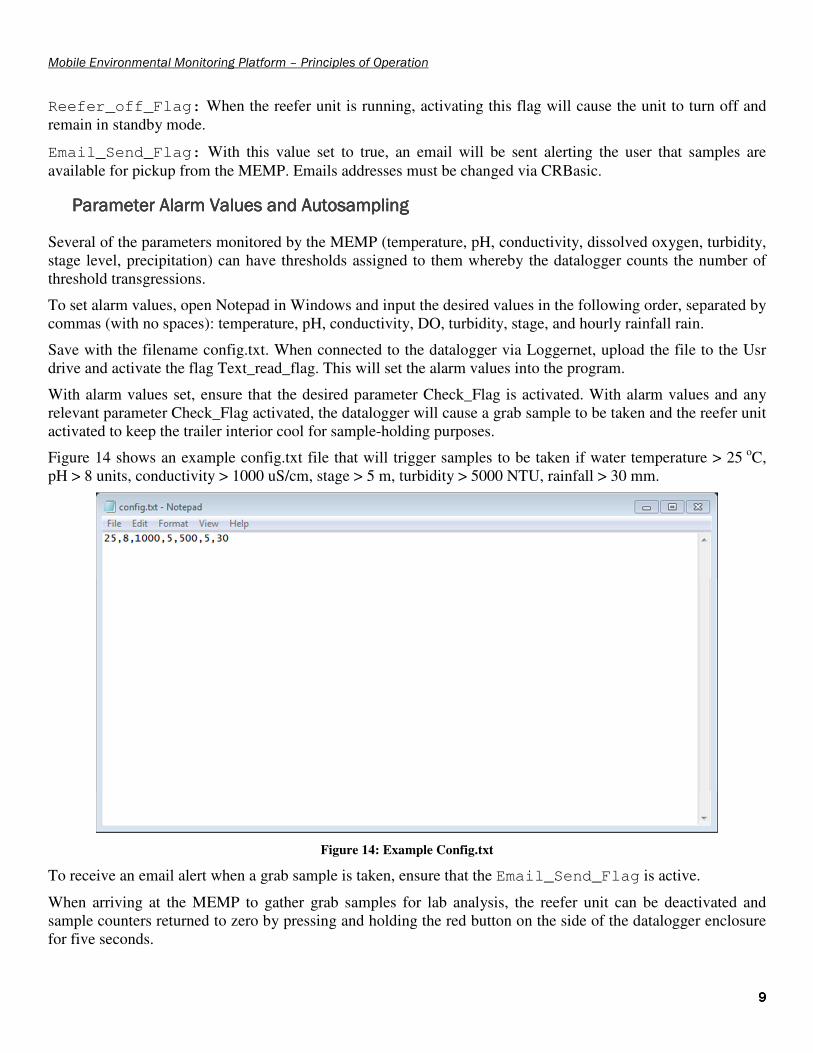
Figure 14 shows an example config.txt file that will trigger samples to be taken if water temperature > 25 oC, pH > 8 units, conductivity > 1000 uS/cm, stage > 5 m, turbidity > 5000 NTU, rainfall > 30 mm.
Figure 14: Example Config.txt
To receive an email alert when a grab sample is taken, ensure that the Email_Send_Flag is active.
When arriving at the MEMP to gather grab samples for lab analysis, the reefer unit can be deactivated and sample counters returned to zero by pressing and holding the red button on the side of the datalogger enclosure for five seconds.

Mobile Environmental Monitoring Platform – Principles of Operation
10101010
SummarySummarySummarySummary
Effective operation of the MEMP requires a diverse range of background knowledge in safe trailering techniques, weather and water monitoring station setup, and equipment programming. This manual can only provide a brief overview of the principles of use and any user should be familiar with the attached documents in Appendix I – including an understanding of LAN administration and off-grid power budgeting.

Mobile Environmental Monitoring Platform – Principles of Operation
11111111
Appendix I.Appendix I.Appendix I.Appendix I. Documents and ManualsDocuments and ManualsDocuments and ManualsDocuments and Manuals
Electric Braking UnitElectric Braking UnitElectric Braking UnitElectric Braking Unit
Double-click for contents.

Mobile Environmental Monitoring Platform – Principles of Operation
12121212
Electronic DocumentsElectronic DocumentsElectronic DocumentsElectronic Documents
Protocol Manual for the Operation and Maintenance of Campbell Scientific Canada Corp. Quick Deploy
Weather Systems. (2012). Campbell Scientific Canada Corp.
• Not yet published
Hydrolab DS5, DS5, and MS5 Water Quality Multiprobes. (2006). Hach Company.
• http://s.campbellsci.com/documents/ca/manuals/series_5_man.pdf
Protocols Manual for Real-Time Water Quality Monitoring in NL. (2013). Environment and Conservation.
• http://www.env.gov.nl.ca/env/waterres/rti/rtwq/NL_RTWQ_Manual.pdf
Temperature / Relative Humidity Sensor (HC-S3)
• http://www.campbellsci.ca/hc-s3
Tipping Bucket Rain Gauge (TE525M-L)
• http://s.campbellsci.com/documents/ca/manuals/te525_man.pdf
Anemometer (05103-10)
• http://s.campbellsci.com/documents/ca/manuals/rmy_man.pdf
CC5MPX Digital Network Camera
• http://s.campbellsci.com/documents/ca/manuals/cc5mpx_man.pdf
Raven X Sierra Wireless Cellular Modem
• http://s.campbellsci.com/documents/ca/manuals/ravenx_hspa_man.pdf
Ott Compact Bubble Sensor (CBS)
• http://s.campbellsci.com/documents/ca/manuals/cbs_man.pdf
CR1000 Measurement and Control System
• http://s.campbellsci.com/documents/ca/manuals/cr1000_man.pdf
Teledyne ISCO 6712 Autosampler
• http://www.isco.com/pcfiles/PartPDF/SL000005/UP001BM3.pdf

Mobile Environmental Monitoring Platform – Principles of Operation
13131313
Spill Contingency PlanSpill Contingency PlanSpill Contingency PlanSpill Contingency Plan
Double-click for contents.

Mobile Environmental Monitoring Platform – Principles of Operation
14141414
Appendix II.Appendix II.Appendix II.Appendix II. CRBasicCRBasicCRBasicCRBasic ProgramProgramProgramProgram
'Program for MEMP trailer
'Author DJ Snodgrass - Campbell Scientific Canada
and Ryan Pugh - Gov NFLD
'Date: June 2, 2011
'Current Revision: August 2, 2014
'Program Notes
'
'Checks for Autosamples are taken no more
frequently than every 2 hours.
'Note that when program is first compiled, the
first autosample cannot be taken
'for 2 hours after commencement of program
operation.
'
'Relay powering cell modem provides ten minutes of
connectivity at the top of each hour.
'Declare Public Variables
Public PTemp
Public batt_volt
Public AirTemp
Public RH
Public WS_kph
Public WindDir
Public Rain
Public DS5(7)
Public CBS(7)
'Sample Trigger Counters
Public STC
Public CTC
Public PTC
Public TTC
Public RTC
Public LTC
Public WTTC
'Variables used for email send out of sample
counts
Public EmailServerResponse As String
Public EmailResult
Public EmailBody As String * 300
Public EmailSTR1 As String * 120
Public EmailSTR2 As String * 120
Public EmailSTR3 As String * 30
'Variables used for File Handling
Public FileHandle
Public File_Text As String * 50
Public File_Parse(7)
Public Text_Write_Flag As Boolean
Public Text_Read_Flag As Boolean
Public Timer_Count
Public Daily_Rainfall
'*************************************************
*****************************
'Program Functionality Flags. Set flags as
necessary to enable communications.
'*************************************************
*****************************
'Threshold Triggers
Public Stage_Check_Flag As Boolean
Public Cond_Check_Flag As Boolean
Public Turb_Check_Flag As Boolean
Public PH_Check_Flag As Boolean
Public LDO_Check_Flag As Boolean
Public WaterTmp_Check_Flag As Boolean
Public Rain_Check_Flag As Boolean
'Email Triggers
Public Email_Send_Flag As Boolean
Public Email_Test_Flag As Boolean
'CC5MPX Camera Trigger
Public CC5MPX_Trigger_Flag As Boolean
'Autosampler and Reefer Triggers
Public Sample_Trigger As Boolean
Public Reefer_on_Flag As Boolean
Public Reefer_off_Flag As Boolean
'Reset Sample counts and Call Reefer_Off
Public Port5Status As Boolean
Dim CBS_Purge
Alias DS5(1) = Water_Temperature
Alias DS5(2) = PH
Alias DS5(3) = Conductivity
Alias DS5(4) = TDS
Alias DS5(5) = LDO_sat
Alias DS5(6) = LDO_mg_L
Alias DS5(7) = Turbidity
Alias CBS(1) = Stage_m
Alias CBS(2) = Stage_cm
Alias CBS(3) = Stage_ft
Alias CBS(4) = CBS_Pressure_mbar
Alias CBS(5) = CBS_Pressure_psi
Alias CBS(6) = CBS_Temperature
Alias CBS(7) = CBS_Status
'Met Units
Units PTemp = DegC
Units batt_volt = VoltsDC
Units AirTemp = DegC
Units RH = %
Units WS_kph = Km/Hr
Units WindDir = Degrees
Units Rain = mm
'DS5 Units
Units Water_Temperature = DegC
Units PH = Unit.s
Units Conductivity = uS/cm
Units TDS = g/L
Units LDO_sat = %
Units LDO_mg_L = mg/L
Units Turbidity = NTU
'CBS Units
Units Stage_m = m
Units Stage_cm = cm
Units Stage_ft = ft
Units CBS_Pressure_mbar = mbar
Units CBS_Pressure_psi = PSI
'*************************************************
****************************
'Enter Threshold Values here!
'*************************************************
****************************
Public Stage_Trig_Value
Public Rain_Trig_Value
Public Cond_Trig_Value
Public Turb_Trig_Value
Public PH_trig_Value
Public LDO_Trig_Value
Public Water_Tmp_Trig_Value
Const CRLF = CHR(13) + CHR(10)
'*************************************************
***************************
'Enter Email Address(es) here for notification of
Samples
'*************************************************
***************************
Const EmailAddress = "[email protected]"
Const Sample_Trig_Time = 120 'Enter Time in
minutes for autosample interval
'Add Daily Troubleshotting table.
DataTable (TrbleSht,1,-1)
DataInterval (0,1440,Min,10)
Maximum (1,batt_volt,FP2,False,False)
Minimum (1,batt_volt,FP2,False,True)
Maximum (1,PTemp,FP2,False,False)
Minimum (1,PTemp,FP2,False,False)
Sample (1,CBS_Status,FP2)
EndTable
'Add Main Data table
DataTable (FifteenMin,1,-1)
DataInterval (0,15,Min,10)
Average (1,AirTemp,FP2,False)
FieldNames ("AirTemp:TA")
Average (1,RH,FP2,False)
FieldNames ("RH:XR")
Average (1,WS_kph,FP2,False)
FieldNames ("WS_kph_avg:US")
Maximum (1,WS_kph,FP2,False,True)
FieldNames ("WS_kph_Gust:UP")
SampleMaxMin (1,WindDir,FP2,False)
FieldNames ("WindDir_Gust:UR")
Average(1,WindDir,FP2,False)
FieldNames ("WindDir:UD")
Totalize (1,Rain,FP2,False)
FieldNames ("Rain:PU")
Sample (1,Water_Temperature,FP2)
FieldNames ("Water_Temperature:TW")
Sample (1,PH,FP2)
FieldNames ("PH:WP")
Sample (1,Conductivity,FP2)
FieldNames ("Conductivity:WC")
Sample (1,TDS,IEEE4)
FieldNames ("TDS:WZ")
Sample (1,LDO_sat,FP2)
FieldNames ("LDO_Sat:WX")
Sample (1,LDO_mg_L,FP2)
FieldNames ("LDO_mg:WO")
Sample (1,Turbidity,FP2)
FieldNames ("Turbidity:WT")
Sample (1,Stage_m,IEEE4)
FieldNames ("Stage_m:HG")
EndTable
DataTable (Daily_Rainfall,True,5)
TableHide
DataInterval (0,1,Day,10)
Totalize (1,Rain,FP2,False)
EndTable
Sub Text_Write
File_Text = Water_Tmp_Trig_Value + "," +
PH_trig_Value + "," + Cond_Trig_Value + "," +
LDO_Trig_Value + "," + Turb_Trig_Value + "," +
Stage_Trig_Value + "," + Rain_Trig_Value + CRLF
FileHandle = FileOpen ("USR:Config.txt","w",-1)
FileWrite (FileHandle,File_Text,0)
FileClose (FileHandle)
EndSub
Sub Text_Read
FileHandle = FileOpen ("USR:Config.txt","r",0)
FileReadLine (FileHandle,File_Text,50)
SplitStr (File_Parse(1),File_Text,"",7,0)
Water_Tmp_Trig_Value = File_Parse(1)
PH_trig_Value = File_Parse(2)
Cond_Trig_Value = File_Parse(3)
LDO_Trig_Value = File_Parse(4)
Turb_Trig_Value = File_Parse(5)
Stage_Trig_Value = File_Parse(6)
Rain_Trig_Value = File_Parse(7)
FileClose (FileHandle)
EndSub
Sub Reefer_on
'Pulse Port 2 to turn on reefer unit
PortSet(2,1)
'Delay 2 seconds to ensure pulse recieved
Delay(1,2,2)
'Turn off port after pulse completion
PortSet(2,0)
EndSub
Sub Reefer_off
'Pulse Port 8 to turn off reefer unit
PortSet(8,1)
'Delay 2 seconds to ensure pulse recieved
Delay(1,2,2)
'Turn off port after pulse completion
PortSet(8,0)
EndSub
Sub Timer_Sub
Timer(1,Min,2)
EndSub
Sub Check_for_Sample_Triggers
Timer_Count = Timer(1,Min,4)
If Timer_Count >= Sample_Trig_Time Then
If Stage_Check_Flag = True Then
If Stage_m >=Stage_Trig_Value Then
''Send a pulse to port 6
PortSet(6,1)
'Delay for 5 seconds (hold pulse)
Delay(1,5,2)
'Turn off pulse at ports 6
PortSet(6,0)
Call Reefer_on
EndIf
EndIf
If Cond_Check_Flag = True Then
If Conductivity >=Cond_Trig_Value Then
''Send a pulse to port 6
PortSet(6,1)
'Delay for 5 seconds (hold pulse)
Delay(1,5,2)
'Turn off pulse at ports 6
PortSet(6,0)
Call Reefer_on
Call Timer_Sub
EndIf
EndIf
If Turb_Check_Flag = True Then
If Turbidity >= Turb_Trig_Value Then
''Send a pulse to port 6
PortSet(6,1)
'Delay for 5 seconds (hold pulse)
Delay(1,5,2)
'Turn off pulse at ports 6
PortSet(6,0)
Call Reefer_on
EndIf
EndIf
If PH_Check_Flag = True Then
If PH >= PH_trig_Value Then
''Send a pulse to port 6
PortSet(6,1)
'Delay for 5 seconds (hold pulse)
Delay(1,5,2)
'Turn off pulse at ports 6
PortSet(6,0)
Call Reefer_on
EndIf
EndIf
If LDO_Check_Flag = True Then
If LDO_mg_L <=LDO_Trig_Value Then
''Send a pulse to port 6
PortSet(6,1)

Mobile Environmental Monitoring Platform – Principles of Operation
15151515
'Delay for 5 seconds (hold pulse)
Delay(1,5,2)
'Turn off pulse at ports 6
PortSet(6,0)
Call Reefer_on
EndIf
EndIf
If WaterTmp_Check_Flag = True Then
If Water_Temperature >= Water_Tmp_Trig_Value
Then
''Send a pulse to port 6
PortSet(6,1)
'Delay for 5 seconds (hold pulse)
Delay(1,5,2)
'Turn off pulse at ports 6
PortSet(6,0)
Call Reefer_on
EndIf
Call Timer_Sub
EndIf
EndIf
If TimeIntoInterval(0,15,min) Then
If Stage_Check_Flag = TRUE AND Stage_m >=
Stage_Trig_Value Then STC = STC + 1
If Cond_Check_Flag = TRUE AND Conductivity >=
Cond_Trig_Value Then CTC = CTC + 1
If Turb_Check_Flag = TRUE AND Turbidity >=
Turb_Trig_Value Then TTC = TTC + 1
If PH_Check_Flag = TRUE AND PH >=
PH_trig_Value Then PTC = PTC + 1
If LDO_Check_Flag = TRUE AND LDO_mg_L <=
LDO_Trig_Value OR LDO_mg_L <> 0 Then LTC = LTC + 1
If WaterTmp_Check_Flag = TRUE AND
Water_Temperature >= Water_Tmp_Trig_Value Then
WTTC = WTTC + 1
EndIf
EndSub
Sub Daily_Rainfall_Check
GetRecord (Daily_Rainfall,Daily_Rainfall,1)
If Daily_Rainfall >= Rain_Trig_Value Then
RTC = RTC + 1
''Send a pulse to port 6
PortSet(6,1)
'Delay for 5 seconds (hold pulse)
Delay(1,5,2)
'Turn off pulse at ports 6
PortSet(6,0)
Call Reefer_on
EndIf
EndSub
'Main Program
BeginProg
SetStatus ("UsrDriveSize","3146512")
FileHandle = FileOpen ("USR:config.txt","r",-1)
If FileHandle > 0 Then
Call Text_Read
EndIf
'configure Port 5 as input
PortsConfig (&B10110010,&B10100010)
Scan (5,Sec,0,0)
If Reefer_on_Flag = True Then
Call Reefer_on
Reefer_on_Flag = False
EndIf
If Reefer_off_Flag = True Then
Call Reefer_off
Reefer_off_Flag = False
EndIf
If Sample_Trigger = True Then
PortSet(6,1)
Delay (1,2,Sec)
PortSet(6,0)
EndIf
If Text_Write_Flag = True Then
Call Text_Write
Text_Write_Flag = False
EndIf
If Text_Read_Flag = True Then
Call Text_Read
Text_Read_Flag = False
EndIf
'Pulse Port 7 to trigger CC5MPX camera
If TimeIntoInterval(0,60,Min) AND
CC5MPX_Trigger_Flag = TRUE Then
PortSet(7,1)
ElseIf TimeIntoInterval(1,60,Min) Then
PortSet(7,0)
EndIf
'Turn on Relay Power (Switch and Modem) at the
top of the hour for 10 minutes
If TimeIntoInterval(0,60,Min) Then
SW12(1)
ElseIf TimeIntoInterval(10,60,Min) Then
SW12(0)
EndIf
Timer(1,Min,0)
'Check for button press on Port 5 and reset
Reefer to Off position and clear counter Values
PortGet (Port5Status,5)
If Port5Status = True Then
Call Reefer_off
STC = 0
CTC = 0
TTC = 0
PTC = 0
LTC = 0
WTTC = 0
RTC = 0
EndIf
PanelTemp (PTemp,_60Hz)
Battery (batt_volt)
'Measure TTH-1315 Temperature and RH Sensor.
'For other trailers (port 3/4)
'consider adjusting settling time (make it
greater than 0)
VoltSe (AirTemp,1,mV2500,3,True,0,_60Hz,0.1,-
40)
VoltSe (RH,1,mV2500,4,True,0,_60Hz,0.1,0)
'Measure Wind Speed / Direction: 05103-10-L
Anemometer
PulseCount (WS_kph,1,1,1,1,0.3528,0)
BrHalf (WindDir,1,mV2500,1,1,1,2500,True
,0,_60Hz,355,0)
'Correct Wind direction over ranges:
If WindDir>=360 Then WindDir=0
If WindDir < 0 Then WindDir = 0
'Measure one TE525M rain gauge.
PulseCount (Rain,1,2,2,0,0.1,0)
'Mesure Hydrolab, OTT CBS bubbler and
Spectro::lyser every 15 Minutes (on the hour -
system clock)
If TimeIntoInterval (0,15,Min) Then
'Measure the Hydrolab sonde
SDI12Recorder (DS5(),1,0,"C!",1.0,0)
'Measure CBS bubbler
SDI12Recorder(CBS(),1,1,"C!",1,0)
EndIf
'Perform a purge of the CBS during the first
minute of every day.
If TimeIntoInterval (0,1440,Min) Then
SDI12Recorder (CBS_Purge,1,0,"OXP1!",1.0,0)
EndIf
If TimeIntoInterval(1,1440,Min) Then
SDI12Recorder (CBS_Purge,1,0,"OXP0!",1.0,0)
EndIf
If Rain_Check_Flag = True Then
CallTable Daily_Rainfall
If TimeIntoInterval(1,1440,min) Then
Call Daily_Rainfall_Check
EndIf
EndIf
Call Check_for_Sample_Triggers
CallTable TrbleSht
CallTable FifteenMin
NextScan
SlowSequence
'Every six hours, check for water samples. If
samples are present, build the email string and
send to addresses specified.
Scan (1,Min,0,0)
If Email_Send_Flag = True OR Email_Test_Flag =
TRUE Then
If TimeIntoInterval(0,6,hr) OR
Email_Test_Flag = TRUE Then
'check for Samples
If STC >0 OR CTC >0 OR TTC >0 OR PTC >0 OR
LTC >0 OR WTTC >0 OR Email_Test_Flag = TRUE Then
EmailSTR1 = "Samples Ready for Pickup."
+ CRLF + "Stage Counts: " + STC + CRLF +
"Conductivity Counts: " + CTC + CRLF + "Turbitiy
Counts: "
EmailSTR2 = TTC + CRLF + "RainFall
Counts: " + RTC + CRLF + "PH Counts: " + PTC +
CRLF + "LDO Counts: " + LTC + CRLF
EmailSTR3 = "Water Temperature Counts: "
+ WTTC + CRLF
EmailBody = EmailSTR1 + EmailSTR2 +
EmailSTR3
EmailResult = EmailSend
("smtp.gmail.com",EmailAddress,"[email protected]
m","MEMP: Samples Ready for
Pickup",EmailBody,"","[email protected]","envcwr
md",EmailServerResponse)
EndIf
EndIf
EndIf
Email_Test_Flag = FALSE
NextScan
EndSequence
EndProg

Mobile Environmental Monitoring Platform – Principles of Operation
16161616
Appendix III.Appendix III.Appendix III.Appendix III. Important Login InformationImportant Login InformationImportant Login InformationImportant Login Information
Login InformationLogin InformationLogin InformationLogin Information
Telus APN Username: [email protected] Password: 09608987183
Gmail SMTP Server Login Server: smtp.gmail.com Username: [email protected] Password: envcwrmd.
CR1000 FTP Server User: wrmd Password: AX59*$
DriveHQ.com FTP Server Login Username: wrmdgovnl Password: wrmd3597
Raven X Modem/Gateway Login Username: user Password: AX59*$
CC5MPX Login Username: wrmd Password: AX59*$
MEMP LAN InformationMEMP LAN InformationMEMP LAN InformationMEMP LAN Information
CR1000 IP Address External IP: 74.49.37.14:6785 LAN IP: 192.168.1.91
Raven X IP Address External IP: 74.49.37.14 Gateway IP: 192.168.1.1 DHCP Range: 192.168.1.95 – 192.168.1.100
CC5MPX LAN IP: 192.168.1.90:80
Mobile Environmental Monitoring Platform – Principles of Operation
17171717
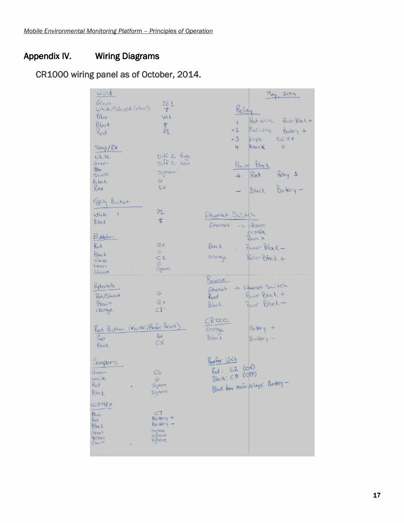
Appendix IV.Appendix IV.Appendix IV.Appendix IV. Wiring DiagramsWiring DiagramsWiring DiagramsWiring Diagrams
CR1000 wiring panelCR1000 wiring panelCR1000 wiring panelCR1000 wiring panel as of October, 2014.as of October, 2014.as of October, 2014.as of October, 2014.

Mobile Environmental Monitoring Platform – Principles of Operation
18181818
Thermo KingThermo KingThermo KingThermo King MDMDMDMD----100100100100 Reefer Unit Relay WiringReefer Unit Relay WiringReefer Unit Relay WiringReefer Unit Relay Wiring