Minnesota Department of Transportation (Mn/DOT) Historic ...

MMnn//DDOOTT IInntteelllliiggeenntt TTrraannssppoorrttaattiioonn
SSyysstteemm ((IITTSS)) DDeessiiggnn MMaannuuaall
Draft Printed: February 27, 2010
22001100
Office of Traffic,
Safety, & Technology
(OTST)

Mn/DOT ITS Design Manual
2010 i
TABLE OF CONTENTS
1. INTRODUCTION ............................................................................................................................... 1‐1 1.1 What is ITS? ........................................................................................................................................... 1‐1 1.2 Purpose of Manual ............................................................................................................................... 1‐1 1.3 Scope of Manual ................................................................................................................................... 1‐1 1.4 Manual References ............................................................................................................................... 1‐2
2. DEFINITIONS .................................................................................................................................... 2‐1
3. ITS WARRANTS DISCUSSION ............................................................................................................ 3‐1 3.1 DMS Warrant ........................................................................................................................................ 3‐1 3.1.1 DMS Warrant ‐ 1: To Inform Travelers of Weather Conditions ..................................................... 3‐2 3.1.2 DMS Warrant ‐ 2: To Inform Travelers of Traffic Conditions ......................................................... 3‐3 3.1.3 DMS Warrant ‐ 3: Changing Traffic Conditions .............................................................................. 3‐4 3.1.4 DMS Warrant ‐ 4: Special Events .................................................................................................... 3‐5 3.1.5 DMS Warrant ‐ 5: Parking Availability ............................................................................................ 3‐6 3.1.6 DMS Warrant ‐ 6: Transit Park and Ride Lot Availability ............................................................... 3‐7 3.1.7 DMS Warrant ‐ 7: Evacuation Routes ............................................................................................. 3‐8 3.1.8 DMS Warrant ‐ 8: Jurisdictional Information ................................................................................. 3‐9
3.2 CCTV Warrant ..................................................................................................................................... 3‐10 3.2.1 CCTV Warrant ‐ 1: Traffic Observation ......................................................................................... 3‐10 3.2.2 CCTV Warrant ‐ 2: Traffic Incident or Event Verification ............................................................. 3‐11 3.2.3 CCTV Warrant ‐ 3: Weather Verification ...................................................................................... 3‐12 3.2.4 CCTV Warrant ‐ 4: Traveler Information ...................................................................................... 3‐13 3.2.5 CCTV Warrant ‐ 5: Field Device Verification ................................................................................. 3‐14
3.3 HAR Warrant ....................................................................................................................................... 3‐15 3.3.1 HAR Warrant ‐ 1: Weather and Driving Conditions ..................................................................... 3‐15 3.3.2 HAR Warrant ‐ 2: Venue Parking .................................................................................................. 3‐16 3.3.3 HAR Warrant ‐ 3: Changing Traffic Conditions ............................................................................. 3‐17 3.3.4 HAR Warrant ‐ 4: Special Events ................................................................................................... 3‐18
3.4 RWIS Warrant ..................................................................................................................................... 3‐19 3.4.1 RWIS Warrant ‐ 1: Support Maintenance Activities at Key Locations ......................................... 3‐19 3.4.2 RWIS Warrant ‐ 2: Support Regional or Statewide Weather Monitoring or Modeling .............. 3‐20 3.4.3 RWIS Warrant ‐ 3: Support Traveler Information Systems Through RWIS at Key Locations ..... 3‐21
4. SYSTEM ENGINEERING PROCESS ..................................................................................................... 4‐1 4.1 Regional ITS Architecture ..................................................................................................................... 4‐1 4.1.1 ITS Architecture and System Engineering Checklist ....................................................................... 4‐1
4.2 Concept of Operations ......................................................................................................................... 4‐2 4.3 Requirements ....................................................................................................................................... 4‐2 4.4 Test and Acceptance Plans ................................................................................................................... 4‐2 4.5 Operations and Maintenance Plan ...................................................................................................... 4‐3
5. ITS COMPONENTS DISCUSSION ....................................................................................................... 5‐1 5.1 IRIS Software ......................................................................................................................................... 5‐1 5.2 Detection ............................................................................................................................................... 5‐2 5.2.1 Types of Detection .......................................................................................................................... 5‐3 5.2.2 Inductive Loop Detectors ................................................................................................................ 5‐4 5.2.3 Video Detectors ............................................................................................................................... 5‐4

Mn/DOT ITS Design Manual
2010 ii
5.2.4 Radar/Microwave Detectors........................................................................................................... 5‐5 5.2.5 Detector Technology Strengths and Weaknesses ......................................................................... 5‐1 5.2.6 Vehicle Classification ....................................................................................................................... 5‐1 5.2.7 Speed Monitoring ............................................................................................................................ 5‐3 5.2.8 Wrong‐Way Detection .................................................................................................................... 5‐3 5.2.9 Detection Area Discussion .............................................................................................................. 5‐4 5.2.10 Setup vs. Design Parameters .......................................................................................................... 5‐4
5.3 Closed Circuit Television (CCTV) ........................................................................................................... 5‐4 5.3.1 The Camera System ......................................................................................................................... 5‐4 5.3.2 CCTV Mounting ................................................................................................................................ 5‐7 5.3.3 Performance and Bandwidth .......................................................................................................... 5‐7 5.3.4 Camera Control ............................................................................................................................... 5‐7 5.3.5 Temporary Cameras ........................................................................................................................ 5‐7 5.3.6 Camera Housing .............................................................................................................................. 5‐8
5.4 Dynamic Message Signs (DMS) ............................................................................................................ 5‐8 5.4.1 DMS Location and Design ............................................................................................................... 5‐9 5.4.2 Sign Types ...................................................................................................................................... 5‐10 5.4.3 Sign Control ................................................................................................................................... 5‐11
5.5 Ramp Meters ...................................................................................................................................... 5‐11 5.5.1 Signal Heads and Mounting .......................................................................................................... 5‐11 5.5.2 Control Cables ............................................................................................................................... 5‐12
5.6 RWIS .................................................................................................................................................... 5‐13 5.7 Dynamic Warning Flashers ................................................................................................................. 5‐14 5.7.1 Flashing Beacons ........................................................................................................................... 5‐14 5.7.2 Flasher Cabinet .............................................................................................................................. 5‐14 5.7.3 Activation ....................................................................................................................................... 5‐14
5.8 Highway Advisory Radio (HAR) .......................................................................................................... 5‐14 5.8.1 Field System ................................................................................................................................... 5‐14
5.9 Electrically Operated Gates? .............................................................................................................. 5‐16 5.10 Intelligent Work Zones? ..................................................................................................................... 5‐16 5.10.1 [Incorporate IWZ Toolbox stuff here] ........................................................................................... 5‐16
5.11 Control Cabinets ................................................................................................................................. 5‐17 5.12 Power .................................................................................................................................................. 5‐17 5.12.1 Service Cabinets for Utility Power ................................................................................................ 5‐17 5.12.2 Grounding and Surge Suppression ............................................................................................... 5‐17 5.12.3 Battery Backup .............................................................................................................................. 5‐17 5.12.4 Solar/Wind Power ......................................................................................................................... 5‐18
5.13 Electronic Communications ............................................................................................................... 5‐18 5.13.1 Communications Standards .......................................................................................................... 5‐18 5.13.2 Grounding and Surge Suppression ............................................................................................... 5‐18 5.13.3 Ethernet ......................................................................................................................................... 5‐18 5.13.4 Fiber Optic ..................................................................................................................................... 5‐18 5.13.5 Wireless ......................................................................................................................................... 5‐18 5.13.6 Leased Lines ................................................................................................................................... 5‐18
5.14 Emerging Technologies ...................................................................................................................... 5‐18
6. SYSTEM DESIGN ............................................................................................................................... 6‐1 6.1 Metro Design Checklist (update for this book) .................................................................................... 6‐1

Mn/DOT ITS Design Manual
2010 iii
6.2 Component Placement and Design ..................................................................................................... 6‐3 6.2.1 Detectors ......................................................................................................................................... 6‐3 6.2.2 CCTV ................................................................................................................................................. 6‐5 6.2.3 DMS .................................................................................................................................................. 6‐5 6.2.4 Control Cabinets .............................................................................................................................. 6‐6 6.2.5 Power ............................................................................................................................................... 6‐6 6.2.6 Communications ............................................................................................................................. 6‐7
6.3 Cables .................................................................................................................................................... 6‐8 6.4 Sizing Power Cables .............................................................................................................................. 6‐8 6.5 Ground Conductors .............................................................................................................................. 6‐8 6.6 Sizing Communications Cables ............................................................................................................. 6‐8 6.7 Metro TMC Lessons Learned ............................................................................................................... 6‐8
7. PLAN DEVELOPMENT ..................................................................................................................... 7‐11 7.1 Required Sheets .................................................................................................................................. 7‐11 7.2 Title Sheet ........................................................................................................................................... 7‐12 7.2.1 Plan Description and Location ...................................................................................................... 7‐12 7.2.2 Governing Specifications and Index of Sheets ............................................................................. 7‐12 7.2.3 Plan Preparation Certification Note ............................................................................................. 7‐13 7.2.4 Project Numbers and Sheet Numbers .......................................................................................... 7‐14 7.2.5 Signature Block .............................................................................................................................. 7‐14 7.2.6 Index Map ...................................................................................................................................... 7‐14 7.2.7 Project Location ............................................................................................................................. 7‐15 7.2.8 Plan Revisions Block ...................................................................................................................... 7‐16
7.3 General Layout Sheets ........................................................................................................................ 7‐16 7.4 TMS Components Sheet ..................................................................................................................... 7‐17 7.4.1 Legend of Symbols ........................................................................................................................ 7‐18 7.4.2 Utility Notes ................................................................................................................................... 7‐18 7.4.3 List of Utility Ownership ................................................................................................................ 7‐20 7.4.4 Standard Plates Summary ............................................................................................................. 7‐20
7.5 Quantities Sheet ................................................................................................................................. 7‐21 7.6 Construction Plans .............................................................................................................................. 7‐21 7.7 Detail Tabulation ................................................................................................................................ 7‐23 7.8 Detail Sheets ....................................................................................................................................... 7‐23 7.8.1 Handhole Detail ............................................................................................................................. 7‐24 7.8.2 Fiber Optic Pulling Vault ................................................................................................................ 7‐24 7.8.3 Fiber Optic Splice Vault ................................................................................................................. 7‐25 7.8.4 Typical Foundation Details ............................................................................................................ 7‐26 7.8.5 Fiber Distribution Patching Shelter ............................................................................................... 7‐26 7.8.6 Typical Cabinet Installation ........................................................................................................... 7‐27 7.8.7 TMS Service Cabinet ...................................................................................................................... 7‐27 7.8.8 Typical DMS 334 Cabinet Installation ........................................................................................... 7‐28 7.8.9 One‐way Ramp Control Signal Detail............................................................................................ 7‐28 7.8.10 Ramp Control Signal Control Cable Termination Guide .............................................................. 7‐29 7.8.11 Signing Layout Detail (Without HOV) ........................................................................................... 7‐29
7.9 Wiring Diagrams ................................................................................................................................. 7‐37 7.10 Fiber Connection Charts ..................................................................................................................... 7‐37
8. STANDARD AND SPECIAL PROVISIONS ............................................................................................ 8‐1

Mn/DOT ITS Design Manual
2010 iv
8.1 Mn/DOT Standard Specifications for Construction ............................................................................. 8‐1 8.1.1 Format of the “Spec Book” ............................................................................................................. 8‐1 8.1.2 Format of Mn/DOT 2565 (Traffic Signals) ...................................................................................... 8‐1 8.1.3 Supplemental Specifications ........................................................................................................... 8‐2
8.2 Special Provisions ................................................................................................................................. 8‐3 8.3 Approved Products List ........................................................................................................................ 8‐4
9. APPENDIX ........................................................................................................................................ 9‐1
Mn/DOT ITS Design Manual
2010 v
LIST OF FIGURES
Figure 1 – IRIS DMS Display .................................................................................................................................. 5‐2
Figure 2 – Classes available from inductive‐loop classifying sensor .................................................................. 5‐1
Figure 3 – Loop Based Wrong Way Detection .................................................................................................... 5‐4
Figure 4 – CCTV Pole Installation Detail ............................................................................................................... 5‐6
Figure 4 – Bridge Mounted Dynamic Message Sign ........................................................................................... 5‐9
Figure 6 – Ramp Meter (One‐Way) Detail ......................................................................................................... 5‐12
LIST OF TABLES
Table 1 – Manual References ............................................................................................................................... 1‐2
Table 2 – Glossary of ITS Terms ........................................................................................................................... 2‐1
Table 3 – Detector Technology Strengths and Weaknesses .............................................................................. 5‐1

Mn/DOT ITS Design Manual
2010 1-1
1. INTRODUCTION
1.1 What is ITS?
Intelligent Transportation Systems or ITS is the application of advanced technology to solve transportation problems. ITS supports the movement of people, goods, and services.
ITS improves transportation safety and mobility and enhances productivity through the use of advanced information and communications technologies.
Intelligent transportation systems (ITS) encompass a broad range of wireless and wire line communications‐based information and electronics technologies. When integrated into the transportation system's infrastructure, and in vehicles themselves, these technologies relieve congestion, improve safety and enhance American productivity.
1.2 Purpose of Manual
The purpose of Mn/DOT ITS Design Manual is to give individuals familiar with ITS elements the process and information necessary to design intelligent transportation system (ITS) elements for Mn/DOT. ITS elements have many similarities to traffic signal and roadway lighting elements, but also have many unique characteristics and considerations.
This manual is intended for agency and consultant personnel engaged in ITS component design.
1.3 Scope of Manual
This manual is structured as follows:
Chapter 1 is this introduction to ITS.
Chapter 2 is a glossary of common terms that are used in ITS.
Chapter 3 discusses some warrants for ITS elements.
Chapter 4 describes the systems engineering process.
Chapter 5 is a discussion on ITS components.
Chapter 6 details the ITS design considerations.
Chapter 7 includes plan development.
Chapter 8 discusses the standard and special provisions.
Chapter 9 is the sample plan set.
This Mn/DOT ITS Design manual is not intended to cover all Intelligent Transportation System (ITS) elements. The focus of this manual is on traffic related topics.

Mn/DOT ITS Design Manual
2010 1-2
1.4 Manual References
The pages contained within the manual are current at the time of publishing. Please keep in mind that the reference material is periodically updated, so the user is cautioned against using the reference materials included in the manual indefinitely, without checking the original sources for updates.
The following table lists the reference material used for this manual.
Table 1 – Manual References
USDOT A Guide for HOT Lane Development, Glossary
www.its.dot.gov/JPODOCS/REPTS_TE/13668_files/glossary.htm
FHWA Systems Engineering Guidebook for ITS
www.fhwa.dot.gov/cadiv/segb/index.htm
Guidestar ITS Planning and Regional Architecture
www.dot.state.mn.us/guidestar/2006_2010/its_planning_and_regional_architecture.html
Traffic Engineering Manual (TEM) ‐ August 2007 and March 2008
www.dot.state.mn.us/trafficeng/otepubl/tem/index.html
Mn/DOT Standard Plates – Dates Vary
www.dot.state.mn.us/tecsup/splate/index.html
Standard Signs Summary – 2007
www.dot.state.mn.us/trafficeng/otepubl/2007signsummary.pdf
Enterprise ‐ Warrants for the Installation and Use of Technology Devices for Transportation Operations and Maintenance
www.acconsultants.org/itswarrants/forms/background.html
FHWA Traffic Detector Handbook: Third Edition—Volume I
www.tfhrc.gov/its/pubs/06108/index.htm
*** ABOVE LIST TO BE UPDATED AT END ***

Mn/DOT ITS Design Manual
2010 2-1
2. DEFINITIONS
The chapter defines some of the common terms used in ITS.
Table 2 – Glossary of ITS Terms
Term Definition
Architecture The organizational structure of a system, identifying its components, their interfaces, and a concept of execution among them.
ATIS Advanced Transportation Information System
ATMS Advanced Transportation Management System
Automatic Vehicle Identification (AVI)
A technology system using transponders on vehicles and outside sensors to determine if vehicles on toll lanes are carrying a valid transponder and what the vehicle’s classification is (truck vs. passenger car, SOV vs. HOV). This system also processes the appropriate toll transaction based on the information.
Blank‐Out Sign (BOS) A type of DMS that has the capability to show a blank message or one fixed message.
Changeable Message Sign
A sign that is capable of displaying one of two or more predefined messages, or a blank message. Personnel in the maintenance and construction field usually use the term CMS regardless of whether new messages can be downloaded or whether only pre‐defined messages can be used (i.e., whether the sign is a VMS or CMS). A trailer mounted CMS is called a Portable CMS (PCMS). This manual uses the term DMS whether the sign is a VMS or a CMS or a PCMS.
Closed Circuit Television (CCTV)
A video monitoring and security system used to provide continuous traffic monitoring by the facility operator along the length of the facility and particularly at points of entry and tolling locations.
CMS Changeable Message Sign
Components Components are the named "pieces" of design and/or actual entities [sub‐systems, hardware units, software units] of the system/sub‐system. In system/sub‐system architectures, components consist of sub‐systems [or other variations], hardware units, software units, and manual operations.
Design Those characteristics of a system or components that are selected by the developer in response to the requirements.
Detector Loops (Loop Detector Amplifiers)
An AVC system component imbedded in the pavement and used to detect and classify the type of vehicles passing over them. The loops are linked to the lane controller and can be used individually to count traffic or to trigger the violation enforcement cameras or in tandem to measure vehicle speeds.
DMS (Dynamic Message Sign)
Any sign system that can change the message presented to the viewer such as Variable Message Sign (VMS), Changeable Message Sign (CMS) and Blank‐Out Sign (BOS).

Mn/DOT ITS Design Manual
2010 2-2
Term Definition
DOT Department of Transportation
Dynamic Pricing Tolls that vary in real time in response to changing congestion levels, as opposed to variable pricing that follows a fixed schedule.
Express Lanes A lane or set of lanes physically separated or barriered from the general‐purpose capacity provided within major roadway corridors. Express lane access is managed by limiting the number of entranced and exit points to the facility. Express lanes may be operated as reversible flow facilities or bi‐directional facilities.
FHWA Federal Highway Administration
Firmware The combination of a hardware device and computer instructions and/or computer data that resides as read‐only software on the hardware device.
Gap analysis A technique to assess how far current [legacy] capabilities are from meeting the identified needs, to be used to prioritize development activities. This is based both on how far the current capabilities are from meeting the needs [because of insufficient functionality, capabilities, performance or capacity] and whether the need is met in some places and not others.
Hardware Articles made of material, such as aircraft, ships, tools, computers, vehicles, fittings, and their components [mechanical, electrical, electronic, hydraulic, and pneumatic]. Computer software and technical documentation are excluded.
High‐Occupancy Toll Lanes (HOT lanes)
Managed, limited‐access, and normally barrier‐separated highway lanes that provide free or reduced cost access to HOVs, and also make excess capacity available to other vehicles not meeting occupancy requirements at a market price.
High‐Occupancy Vehicle (HOV)
A passenger vehicle carrying more than a specified minimum number of passengers, such as an automobile carrying more than one or more than two people. HOVs include carpools and vanpools, as well as buses.
HOV lane an exclusive traffic lane or facility limited to carrying HOVs and certain other qualified vehicles.
IEEE Institute of Electrical and Electronics Engineers
Incident Management Managing forms of non‐recurring congestion, such as spills, collisions, immobile vehicles, or any other impediment to smooth, continuous flow of traffic on freeways.
Intelligent Transportation Systems
A broad range of diverse technologies which, when applied to our current transportation system, can help improve safety, reduce congestion, enhance mobility, minimize environmental impacts, save energy, and promote economic productivity. ITS technologies are varied and include information processing, communications, control, and electronics.
Interface The functional and physical characteristics required to exist at a common boundary ‐ in development, a relationship among two or more entities [such as software‐software, hardware‐hardware, hardware‐software, hardware‐user, or

Mn/DOT ITS Design Manual
2010 2-3
Term Definition
software‐user].
ITS Intelligent Transportation System[s]
Lane Controller A micro processor ETC component that coordinates the activities of all equipment in a single lane and generates the transactions assigned to individual customers using that lane.
Lane Management Tools Access – Limiting or metering vehicle ingress to the lane or spacing access so that demand cannot overwhelm HOT lane capacity. See also Limited Access.
Eligibility – Limiting lane use to specific types of users, such as HOVs, motorcycles, low emission vehicles, or trucks. For most typical HOT lane settings, eligibility requirements would be used during selected hours or at specific access ramps.
Pricing – Imposing a user fee on a lane that helps regulate demand by time of day or day of week. The fee increases during periods of highest demand.
Legacy system The existing system to which the upgrade or change will be applied.
Level‐of‐Service (LOS) Also knows as “Traffic Service,” LOS is a qualitative measure describing operational conditions within a traffic stream. LOS assesses conditions in terms of speed and travel time, freedom to maneuver, traffic interruptions, comfort and convenience, and safety. Six levels of service are defined by letter designations from A to F, with LOS A representing the best operating conditions, and LOS F the worst.
Market packages Potential products or sub‐systems that address specific services [as used in an ITS architecture].
Metropolitan Planning Organization (MPO)
Federally mandated regional organizations responsible for comprehensive transportation planning and programming for in urbanized areas. Work products include the Transportation Plan, the Transportation Improvement Program, and the Unified Planning Work Program.
MOE Measure of Effectiveness
National ITS Architecture A general framework for planning, defining, and integrating ITS. It was developed to support ITS implementations over a 20‐year time period in urban, interurban, and rural environments across the country. The National ITS Architecture is available as a resource for any region and is maintained by the USDOT independently of any specific system design or region in the nation.
NEMA National Electrical Manufacturers Association
NTCIP National Transportation Communications for ITS Protocol
Quality assurance A planned and systematic pattern of all actions necessary to provide adequate confidence that management, technical planning, and controls are adequate to establish correct technical requirements for design and manufacturing. And to manage design activity standards, drawings, specifications, or other documents referenced on drawings, lists or technical documents.
Queue Jump Elevated ramps or at‐grade lanes that can be used by motorists stopped in traffic
Mn/DOT ITS Design Manual
2010 2-4
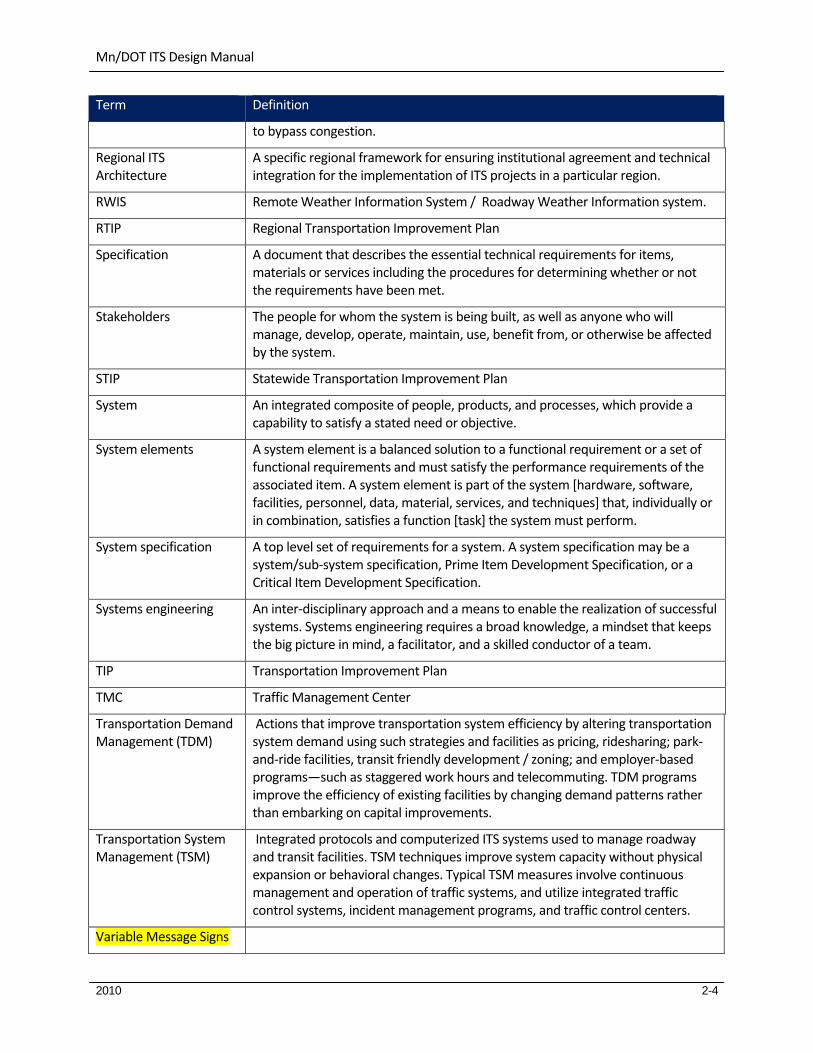
Term Definition
to bypass congestion.
Regional ITS Architecture
A specific regional framework for ensuring institutional agreement and technical integration for the implementation of ITS projects in a particular region.
RWIS Remote Weather Information System / Roadway Weather Information system.
RTIP Regional Transportation Improvement Plan
Specification A document that describes the essential technical requirements for items, materials or services including the procedures for determining whether or not the requirements have been met.
Stakeholders The people for whom the system is being built, as well as anyone who will manage, develop, operate, maintain, use, benefit from, or otherwise be affected by the system.
STIP Statewide Transportation Improvement Plan
System An integrated composite of people, products, and processes, which provide a capability to satisfy a stated need or objective.
System elements A system element is a balanced solution to a functional requirement or a set of functional requirements and must satisfy the performance requirements of the associated item. A system element is part of the system [hardware, software, facilities, personnel, data, material, services, and techniques] that, individually or in combination, satisfies a function [task] the system must perform.
System specification A top level set of requirements for a system. A system specification may be a system/sub‐system specification, Prime Item Development Specification, or a Critical Item Development Specification.
Systems engineering An inter‐disciplinary approach and a means to enable the realization of successful systems. Systems engineering requires a broad knowledge, a mindset that keeps the big picture in mind, a facilitator, and a skilled conductor of a team.
TIP Transportation Improvement Plan
TMC Traffic Management Center
Transportation Demand Management (TDM)
Actions that improve transportation system efficiency by altering transportation system demand using such strategies and facilities as pricing, ridesharing; park‐and‐ride facilities, transit friendly development / zoning; and employer‐based programs—such as staggered work hours and telecommuting. TDM programs improve the efficiency of existing facilities by changing demand patterns rather than embarking on capital improvements.
Transportation System Management (TSM)
Integrated protocols and computerized ITS systems used to manage roadway and transit facilities. TSM techniques improve system capacity without physical expansion or behavioral changes. Typical TSM measures involve continuous management and operation of traffic systems, and utilize integrated traffic control systems, incident management programs, and traffic control centers.
Variable Message Signs

Mn/DOT ITS Design Manual
2010 2-5
Term Definition
(VMS) – clarify A type of DMS, which allows a user to create and download the message to be displayed into the temporary memory area of the sign controller. This manual uses the term DMS whether the sign is a VMS or a CMS.
Video Surveillance The use of pan‐tilt‐zoom, steerable moving picture cameras to survey a toll plaza, ETC collection area, or a segment of roadway to monitor for incidents.
WAN Wide Area Network

Mn/DOT ITS Design Manual
2010 3-1
3. ITS WARRANTS DISCUSSION
The warrants presented in this section are from the ENTERPRISE pooled fund project. Details can be found at the following link:
www.acconsultants.org/itswarrants/forms/background.html
This link is subject to change. The current website is the consultant website working on the ENTERPRISE pooled fund project.
The purpose of this section is to assist in the decision making process of determining if a device is warranted or validate existing device deployments. As part of ENTERPRISE research project, warrants were developed for Dynamic Message Signs (DMS), Closed Circuit Television (CCTV), Highway Advisory Radios (HAR), and Roadway Weather Information Systems (RWIS). These are not official warrants but can be used as guidance toward the determination of ITS components.
3.1 DMS Warrant
For DMS (Dynamic Message Sign) devices, eight (8) warrants have been identified to capture the most common uses of this device. While there are other purposes and uses for DMS, the warrants developed to date have focused on the following eight.
DMS Warrant ‐ 1: To Inform Travelers of Weather Conditions
DMS Warrant ‐ 2: To Inform Travelers of Traffic Conditions
DMS Warrant ‐ 3: Changing Traffic Conditions
DMS Warrant ‐ 4: Special Events
DMS Warrant ‐ 5: Parking Availability
DMS Warrant ‐ 6: Transit Park and Ride Lot Availability
DMS Warrant ‐ 7: Evacuation Routes
DMS Warrant ‐ 8: Jurisdictional Information

Mn/DOT ITS Design Manual
2010 3-2
3.1.1 DMS Warrant ‐ 1: To Inform Travelers of Weather Conditions
The information on the following pages is a handout from the ENTERPRISE research project. The information can be found by going to:
http://www.acconsultants.org/itswarrants/forms/dms1.php
Purpose: To provide road weather information to drivers so that the drivers can choose whether to continue
travel on the route or whether to adjust their speed, route of travel, or divert from the trip in anticipation of
an upcoming weather hazard.
Device is warranted if:
1. If the location is prone to weather situations that travelers would not otherwise be forewarned about
(e.g. spots where fog regularly forms, bridges that ice early, mountain passes with weather that differs
from approaches). And,
2. If there is available road weather information for the area downstream of the candidate DMS location.
And,
3. If there is the capability (either manually by staff members or automated through a condition reporting
system) to create event specific descriptions of weather conditions to be displayed on the DMS. And,
(either 4a, 4b, 4c)
4a. If there is a need to disseminate event specific descriptions (rather than a lower technology approach
such as activating a flashing warning sign that says "Weather Alert When Flashing"). Or
4b. If there are options for either alternate routes or services, that might be described on the DMS, where
travelers may wait out conditions. Or
4c. If flashing beacon signs have been tried and not proven to generate responses from travelers. And
5. If weather events contribute to a significant number of crashes or road closures such that there are
major impacts to travelers (this may include 1 or more annual closures or crashes on a freeway or 10 or
more crashes or closures on arterials).
Warrant Advice:
If the only warrant being met for a DMS is the weather information warrant, then it is recommended that the
lesser technologies are considered before deploying full DMS capabilities.
Partial Warrant Criteria:
If either #1 or #5 above are met, the warrant is considered ‘Partially Met’. If one or more additional purposes
are partially met at this location for this device, the device shall be considered ‘Warranted’.

Mn/DOT ITS Design Manual
2010 3-3
3.1.2 DMS Warrant ‐ 2: To Inform Travelers of Traffic Conditions
The information on the following pages is a handout from the ENTERPRISE research project. The information can be found by going to:
http://www.acconsultants.org/itswarrants/forms/dms2.php
Purpose: To provide current traffic status information (incidents, congestion, travel time, road work) to
drivers so that drivers can choose to divert to avoid the situation, to reduce driver anxiety, and to reduce
crashes involving drivers encountering unexpected stopped traffic.
Device is warranted if:
1. If there is a reliable, real‐time source for status information for the target area; And
2. If the area encounters events that unexpectedly stop traffic an average of at least two times per month;
And
3a. If there are acceptable alternate routes with adequate capacity to accept vehicles that may deviate
based upon the information; Or
3b. If the location is a stretch of road where no alternate route are possible and travelers would benefit from
information describing the cause and/or extent of delays in order to relieve driver anxiety or confusion;
Or
3c. If there are horizontal or vertical curves that create safety issues when traffic is stopped unexpectedly;
And
4. The route being considered for the DMS has on average at least 2 hours of peak period travel where
traffic flow exceeds 1,100 veh/hour/lane or experiences conditions considered Level of Service C.
Partial Warrant Criteria:
If #2 above is met, the warrant is considered ‘Partially Met’. If one or more additional purposes are partially
met at this location for this device, the device shall be considered ‘Warranted’.

Mn/DOT ITS Design Manual
2010 3-4
3.1.3 DMS Warrant ‐ 3: Changing Traffic Conditions
The information on the following pages is a handout from the ENTERPRISE research project. The information can be found by going to:
http://www.acconsultants.org/itswarrants/forms/dms3.php
Purpose: To notify drivers in advance of special changing traffic conditions and roadway configuration
changes associated with road construction or maintenance in order to reduce driver confusion that could
result in a crash.
Device is warranted if:
1. The candidate location is upstream of an area with construction or maintenance activities that are
expected to cause at least 15 minutes of delay to the mainline traffic; And
2. If the candidate location is upstream of traffic control or construction/maintenance activities that are
expected to change more frequently than once every 60 days; And
3. If the speed limit is greater than 45 MPH.
Notes:
A. If question #2 is not met (activities do not change frequently), lower cost static signage is recommended.
B. Portable DMS vs. permanent DMS should be considered based on the expected duration of events
impacting the area.
Partial Warrant Criteria:
If #2 above is met, the warrant is considered ‘Partially Met’. If one or more additional purposes are partially
met at this location for this device, the device shall be considered ‘Warranted’.
Mn/DOT ITS Design Manual
2010 3-5
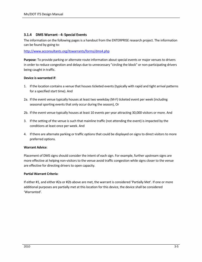
3.1.4 DMS Warrant ‐ 4: Special Events
The information on the following pages is a handout from the ENTERPRISE research project. The information can be found by going to:
http://www.acconsultants.org/itswarrants/forms/dms4.php
Purpose: To provide parking or alternate route information about special events or major venues to drivers
in order to reduce congestion and delays due to unnecessary "circling the block" or non‐participating drivers
being caught in traffic.
Device is warranted if:
1. If the location contains a venue that houses ticketed events (typically with rapid and tight arrival patterns
for a specified start time). And
2a. If the event venue typically houses at least two weekday (M‐F) ticketed event per week (including
seasonal sporting events that only occur during the season), Or
2b. If the event venue typically houses at least 10 events per year attracting 30,000 visitors or more. And
3. If the setting of the venue is such that mainline traffic (not attending the event) is impacted by the
conditions at least once per week. And
4. If there are alternate parking or traffic options that could be displayed on signs to direct visitors to more
preferred options.
Warrant Advice:
Placement of DMS signs should consider the intent of each sign. For example, further upstream signs are
more effective at helping non‐visitors to the venue avoid traffic congestion while signs closer to the venue
are effective for directing drivers to open capacity.
Partial Warrant Criteria:
If either #1, and either #2a or #2b above are met, the warrant is considered ‘Partially Met’. If one or more
additional purposes are partially met at this location for this device, the device shall be considered
‘Warranted’.

Mn/DOT ITS Design Manual
2010 3-6
3.1.5 DMS Warrant ‐ 5: Parking Availability
The information on the following pages is a handout from the ENTERPRISE research project. The information can be found by going to:
http://www.acconsultants.org/itswarrants/forms/dms5.php
Purpose: To provide real time parking availability information to drivers to avoid unnecessary "circling the
block" looking for parking spots.
Device is warranted if:
1. If the area contains ample parking to handle the regular visitors, either during commuter periods or
special events. And
2. If the area contains a set of similar parking garages (similar parking costs) each with generally
comparable ingress and egress and access to events (i.e. parking facilities are all generally equal options
to select from). And
3. If visitors regularly are unable to find parking, and ‘circling the block’ occurs for more than 15 minutes
during the AM commuter period or prior to special events, as visitors seek out parking spaces.
Partial Warrant Criteria:
No partial warrants are identified for this purpose.

Mn/DOT ITS Design Manual
2010 3-7
3.1.6 DMS Warrant ‐ 6: Transit Park and Ride Lot Availability
The information on the following pages is a handout from the ENTERPRISE research project. The information can be found by going to:
http://www.acconsultants.org/itswarrants/forms/dms6.php
Purpose: To provide real time parking availability information to drivers regarding transit park and ride lots.
Device is warranted if:
1. If the area contains park‐and‐ride lots that fill to capacity on either a regular basis or during regularly
occurring events (e.g. inclement weather, sporting events). And
2. If alternate park‐and‐ride lots are available (either upstream or downstream) that do not typically fill to
capacity. And
3. If there is the capability (or willingness) to monitor park‐and‐ride facilities for available spaces.
Partial Warrant Criteria:
No partial warrants are identified for this purpose.

Mn/DOT ITS Design Manual
2010 3-8
3.1.7 DMS Warrant ‐ 7: Evacuation Routes
The information on the following pages is a handout from the ENTERPRISE research project. The information can be found by going to:
http://www.acconsultants.org/itswarrants/forms/dms7.php
Purpose: To provide evacuation route information to drivers during disaster or homeland security events.
Device is warranted if:
1. If the area is a major metropolitan area or has nearby icons that increase the likelihood of requiring an
evacuation (e.g. nuclear reactor, major attraction). And
2. If the area evacuation procedures allow for traffic movements and/or the use of roads that otherwise
are not available to the public (e.g. contra‐flow lanes).
Partial Warrant Criteria:
If #2 above is met, the warrant is considered ‘Partially Met’. If one or more additional purposes are partially
met at this location for this device, the device shall be considered ‘Warranted’.

Mn/DOT ITS Design Manual
2010 3-9
3.1.8 DMS Warrant ‐ 8: Jurisdictional Information
The information on the following pages is a handout from the ENTERPRISE research project. The information can be found by going to:
http://www.acconsultants.org/itswarrants/forms/dms8.php
Purpose: To provide jurisdictional specific information to drivers at or near borders between two
jurisdictions.
Device is warranted if:
1. If there are differing rules or regulations between adjacent jurisdictions. And
2a. If display of differing rules or regulations on static signs would either not attract enough attention, Or
2b. If the rules or regulations change frequently (e.g. load restrictions)
Partial Warrant Criteria:
If #1 above is met, the warrant is considered ‘Partially Met’. If one or more additional purposes are partially
met at this location for this device, the device shall be considered ‘Warranted’.

Mn/DOT ITS Design Manual
2010 3-10
3.2 CCTV Warrant
For CCTV (Closed Circuit Television) devices, five (5) warrants have been identified to capture the most common uses of this device. While there are other purposes and uses for CCTV, the warrants developed to date have focused on the following five.
3.2.1 CCTV Warrant ‐ 1: Traffic Observation
The information on the following pages is a handout from the ENTERPRISE research project. The information can be found by going to:
http://www.acconsultants.org/itswarrants/forms/cctv1.php
Purpose: To visually observe traffic conditions in order to determine if alternate signal timings are
appropriate before implementing alternate traffic signal timing plans remotely.
Device is warranted if:
1. There are typically periods of time at least twice per week of ‘loaded’ cycles (i.e. where the vehicles in
the queue do not all dissipate in one green cycle) that last 15 minutes or longer. And
2. The signalized intersection has sufficient cross street traffic such that visual observation is needed
determining if alternate signal timings are appropriate to benefit the primary direction of flow (i.e. in
order to verify that the secondary street is not backing up). And
3. If pre‐timed flush plans exist and if local policy would only allow implementation of flush timing plans
with visual observation verifying the need.
Partial Warrant Criteria:
If either #1 or #3 above are met, the warrant is considered ‘Partially Met’. If one or more additional purposes
are partially met at this location for this device, the device shall be considered ‘Warranted’.

Mn/DOT ITS Design Manual
2010 3-11
3.2.2 CCTV Warrant ‐ 2: Traffic Incident or Event Verification
The information on the following pages is a handout from the ENTERPRISE research project. The information can be found by going to:
http://www.acconsultants.org/itswarrants/forms/cctv2.php
Purpose: To allow traffic operations personnel or emergency response teams to visually verify traffic flow
and/or incidents (e.g. crashes, debris in roadway) in order to activate or dispatch appropriate response and
post message to traveler information systems.
Device is warranted if:
1. The candidate location would allow visual verification of incidents, queues or other events within an area
that encounters incidents as frequently as twice per month for arterial streets or once per month for
freeways. And
(Either 2a. or 2b.)
2a. The incidents and events that occur on freeways typically cause delay to travelers of at least 15 minutes
while the incident is active and has not been cleared. Or
2b. The incidents and events that occur on arterials typically cause impact travel such that the signal
progression is no longer occurring and vehicles are not clearing green cycles. And
3. The location encounters at least 2 hours per day of peak period travel where traffic flow exceeds 1,100
veh/hr/lane; or Conditions considered Level of Service C; or Average annual daily traffic (AADT) of 16,800
for a 2 lane road; 33,600 for a 4 lane road; 50,400 for a 6 lane road; 67,200 for an 8 lane road.

Mn/DOT ITS Design Manual
2010 3-12
3.2.3 CCTV Warrant ‐ 3: Weather Verification
The information on the following pages is a handout from the ENTERPRISE research project. The information can be found by going to:
http://www.acconsultants.org/itswarrants/forms/cctv3.php
Purpose: To allow maintenance dispatchers and traffic control personnel to verify weather conditions on the
roadway, either to guide traveler information dissemination or to dispatch snow removal and treatment
operations.
Device is warranted if:
1. The location typically encounters at least 10 winter weather events each season. And
2. Winter weather events have a significant impact to travelers at this location (due to such circumstances
as either: local terrain, lack of alternate routes, winding or steep routes), and it is a location that travelers
are frequently concerned about. And
3. If there are no nearby weather sensors reporting accurate and real‐time conditions such as visibility,
precipitation, or pavement temperatures, and if nearby weather sensors would be enhanced through
the capability of visual observation.
Partial Warrant Criteria:
If #1 And #3 above are met, the warrant is considered ‘Partially Met’. If one or more additional purposes are
partially met at this location for this device, the device shall be considered ‘Warranted’.

Mn/DOT ITS Design Manual
2010 3-13
3.2.4 CCTV Warrant ‐ 4: Traveler Information
The information on the following pages is a handout from the ENTERPRISE research project. The information can be found by going to:
http://www.acconsultants.org/itswarrants/forms/cctv4.php
Purpose: To allow travelers to understand traffic delay and road weather conditions by viewing images of
the roadway from the Internet prior to departing.
Device is warranted if:
1a. The location visible by the camera image has a history of congestion on a regular basis (i.e. each
commuter day is a candidate for congestion). Or
1b. The location visible by the camera is prone to weather situations that travelers would not otherwise be
forwarned about (e.g. spots where fog regularly forms, bridges that ice early, mountain passes with
weather that differs from approaches). Or
1c. The location visible by the camera image is a remote area that receives considerable traffic volume due
to commercial vehicle traffic or recreational traffic. And
2. The majority of travelers to the area have Internet access in proximity to the area where camera images
are of value to travelers prior to departure.
Partial Warrant Criteria:
If either #1a, #1b, or #1c above are met, the warrant is considered ‘Partially Met’. If one or more additional
purposes are partially met at this location for this device, the device shall be considered ‘Warranted’.

Mn/DOT ITS Design Manual
2010 3-14
3.2.5 CCTV Warrant ‐ 5: Field Device Verification
The information on the following pages is a handout from the ENTERPRISE research project. The information can be found by going to:
http://www.acconsultants.org/itswarrants/forms/cctv5.php
Purpose: To allow traffic or maintenance operations personnel to verify operational functionality of in‐field
devices (such as Dynamic Message Signs, road/lane closure gates, and other devices).
Device is warranted if:
1. The field device visible by the candidate camera location displays critical messages or is critical to where
visual verification is needed And
2. The field device visible by the candidate camera location has history of not responding to remote access.
Or
3. The camera operation would avoid unnecessary trips to verify functionality of the field device.
Warrant Criteria:
If #1 And #2 above are met, Or if #3 above is met, the warrant is considered ‘Warranted’. If one or more
additional purposes are partially met at this location for this device, the device shall be considered
‘Warranted’.

Mn/DOT ITS Design Manual
2010 3-15
3.3 HAR Warrant
For HAR (Highway Advisory Radio) devices, four (4) warrants have been identified to capture the most common uses of this device. While there are other purposes and uses for HAR, the warrants developed to date have focused on the following four.
3.3.1 HAR Warrant ‐ 1: Weather and Driving Conditions
The information on the following pages is a handout from the ENTERPRISE research project. The information can be found by going to:
http://www.acconsultants.org/itswarrants/forms/har1.php
Purpose: To provide road weather information and/or regulatory restriction information (e.g. chain requirements) to drivers in rural areas to alert them to impending conditions.
Device is warranted if:
1. If the location is upstream and within 4 hours driving proximity to locations that are prone to weather
situations that travelers would not otherwise be forewarned about (e.g. spots where fog regularly forms,
bridges that ice early, mountain passes with weather that differs from approaches). And
2. If there is available road weather monitoring devices or manual observations for the area downstream of
the candidate HAR location. And
3. If there is a need to disseminate a detailed report (such as those possible using HAR recordings) as
opposed to flashing beacons or DMS. or
4. If weather events contribute to a significant number of crashes or road closures such that there are
major impacts to travelers (this may include 1 or more annual closures or crashes on an Interstate
highway or 10 or more crashes or closures annually on arterials).
Partial Warrant Criteria:
If #1 And #3 above are met, the warrant is considered ‘Partially Met’. If one or more additional purposes are partially met at this location for this device, the device shall be considered ‘Warranted’.

Mn/DOT ITS Design Manual
2010 3-16
3.3.2 HAR Warrant ‐ 2: Venue Parking
The information on the following pages is a handout from the ENTERPRISE research project. The information can be found by going to:
http://www.acconsultants.org/itswarrants/forms/har2.php
Purpose: To provide parking or route guidance information around major venues where unfamiliar travelers can benefit from verbal explanations (e.g. airports, National Parks, tourist attractions)
Device is warranted if:
1. The venue is visited by at least 10,000 visitors per day (either year‐round or seasonally); And
(Either 2a, 2b, or 2c)
2a. If there are parking and drop‐off/pick‐up options that are not inherently simple enough to disseminate
using static or DMS sign displays; Or
2b. If there are parking options and real‐time parking availability information available for dissemination; Or
2c. If there are more than one primary access routes to the venue covered by the range of the HAR device
(i.e. one HAR device would support all approaches vs. multiple signs being needed) And
Partial Warrant Criteria:
If #2a, #2b, or #2c above are met, the warrant is considered ‘Partially Met’. If one or more additional purposes are partially met at this location for this device, the device shall be considered ‘Warranted’.
Mn/DOT ITS Design Manual
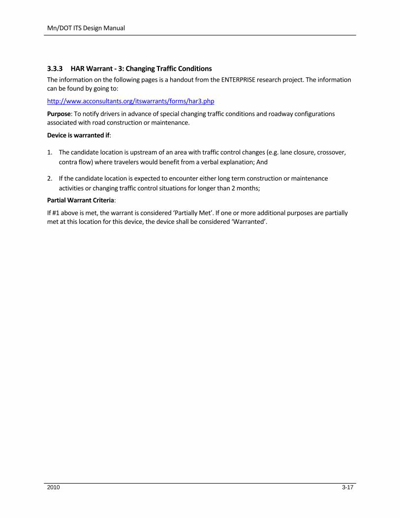
2010 3-17
3.3.3 HAR Warrant ‐ 3: Changing Traffic Conditions
The information on the following pages is a handout from the ENTERPRISE research project. The information can be found by going to:
http://www.acconsultants.org/itswarrants/forms/har3.php
Purpose: To notify drivers in advance of special changing traffic conditions and roadway configurations associated with road construction or maintenance.
Device is warranted if:
1. The candidate location is upstream of an area with traffic control changes (e.g. lane closure, crossover,
contra flow) where travelers would benefit from a verbal explanation; And
2. If the candidate location is expected to encounter either long term construction or maintenance
activities or changing traffic control situations for longer than 2 months;
Partial Warrant Criteria:
If #1 above is met, the warrant is considered ‘Partially Met’. If one or more additional purposes are partially met at this location for this device, the device shall be considered ‘Warranted’.

Mn/DOT ITS Design Manual
2010 3-18
3.3.4 HAR Warrant ‐ 4: Special Events
The information on the following pages is a handout from the ENTERPRISE research project. The information can be found by going to:
http://www.acconsultants.org/itswarrants/forms/har4.php
Purpose: To notify travelers about special events (either prior to the event start date or during the event), alerting travelers to either the impacts of these events on traffic, and to guide event attendees to the event.
Device is warranted if:
1. The temporary event is expected to attract more than 600 vehicles in any one hour period. And
Either 2a. or 2b.
2a. There is a route of travel for event attendees that creates considerably less impact on traffic than other
approaches (i.e. if event attendees can be directed to this route it will minimize impacts). Or
2b. There is an optional route for non‐event traffic to avoid the impacts of this event.
And
3. The message(s) that need to be relayed to the travelers are too complex to convey in a portable sign
(better relayed through spoken reports).

Mn/DOT ITS Design Manual
2010 3-19
3.4 RWIS Warrant
For RWIS (Road Weather Information System) devices, three (3) warrants have been identified to capture the most common uses of this device. While there are other purposes and uses for RWIS, the warrants developed to date have focused on the following two.
3.4.1 RWIS Warrant ‐ 1: Support Maintenance Activities at Key Locations
The information on the following pages is a handout from the ENTERPRISE research project. The information can be found by going to:
http://www.acconsultants.org/itswarrants/forms/rwis1.php
Purpose: To provide site specific atmospheric and road surface condition reports to the agencies responsible for responding to weather events in order to promote safe travel and maintain travelers’ mobility.
Device is warranted if:
Either 1a, 1b, or 1c
1a. The location surrounding the candidate site typically experiences 3 or more crashes related to weather
events each year; Or
1b. The location surrounding the candidate site has experienced 1 or more fatalities per year in crashes
related to weather events; Or
1c. The location surrounding the candidate site is prone to weather events frequently causing difficult
driving conditions (e.g. treacherous roads in winter storms, seasonal or storm related flooding, pockets
of fog); And
Either 2a or 2b
2a. The number of weather events that would be measured and reported at the location is typically more
than 10 per year; Or
2b. The are surrounding the site experiences rare weather events that cause serious operational problems
that often last multiple days (e.g. one major ice storm); And
3. There is not another weather and road surface monitoring station that provides access to the data
within 10 miles of the candidate site.
Note: In using the warrants, it is recommended that the agency research whether any other agencies (National Park System, Department of Natural Resources, Department of Aviation) has weather and/or road condition monitoring stations and make the data publicly available.
Mn/DOT ITS Design Manual
2010 3-20
3.4.2 RWIS Warrant ‐ 2: Support Regional or Statewide Weather Monitoring or Modeling
The information on the following pages is a handout from the ENTERPRISE research project. The information can be found by going to:
http://www.acconsultants.org/itswarrants/forms/rwis2.php
Purpose: To monitor weather and road surface conditions on a regional or statewide grid in order to support wide area weather monitoring and/or modeling and weather prediction.
Device is warranted if:
1. The candidate region or state typically encounters 10 or more inclement weather events each year; And
2a. The transportation agency responsible for maintenance in the region or state has (or is planning) the
ability to utilize grid weather reports (either manually or with the help of a decision support system) to
influence their treatment of conditions; Or
2b. The transportation agency responsible for traveler information in the region or state operates (or is
planning to operate) a region‐wide traveler information system including weather reports throughout
the area; And
3. The transportation agency responsible for maintenance and the agency responsible for traveler
information in the region has examined and/or tested current perpetual data sources (e.g. NWS) and
determined that these sources do not fully meet the needs for the region.

Mn/DOT ITS Design Manual
2010 3-21
3.4.3 RWIS Warrant ‐ 3: Support Traveler Information Systems Through RWIS at Key Locations
X`
The information on the following pages is a handout from the ENTERPRISE research project. The information can be found by going to:
http://www.acconsultants.org/itswarrants/forms/rwis3.php
Purpose: To gather real‐time data describing atmospheric weather and road surface conditions in order inform travelers of the conditions, either through pre‐trip traveler information systems or through en‐route information dissemination systems.
Device is warranted if:
1. The number of crashes related to weather events in the area surrounding the RWIS site (roughly 20 mile
radius) is more than 5 per year; And
2. If there are unique geography conditions at the site that prohibit the prediction of accurate weather
from such systems as NWS forecasts, And
Either 3a, 3b, or 3c
3a. The area in consideration is prone to fog or other local (non regional) visibility restrictions (defined as 10
or more events per year where fog presents dangerous driving conditions); Or
3b. The area in consideration is near an attraction or other draw (winter recreation area, college, resort
area) that attracts visitors traveling at least 1 hour to reach the destination; Or
3c. The area is along a regular commuter path.

Mn/DOT ITS Design Manual
2010 4-1
4. SYSTEM ENGINEERING PROCESS
Include section on favorite links.
System engineering checklist.
From Rashmi Brewer:
FHWA Final Rule ITS Arch and Standards.pdf
Short Architecture and System Engineering Outreach –v5.ppt
http://www.fhwa.dot.gov/cadiv/segb/views/process/index.htm
http://www.dot.state.mn.us/guidestar/2006_2010/its_planning_and_regional_architecture.html
The International Council of Systems Engineers uses the following definition for “systems engineering”: Systems Engineering is an interdisciplinary approach and means to enable the realization of successful systems. It focuses on defining customer needs and required functionality early in the development cycle, documenting requirements, and then proceeding with design synthesis and system validation while considering the complete problem:
Operations
Cost & Schedule
Performance
Training & Support
Test
Manufacturing
Disposal
Systems Engineering integrates all the disciplines and specialty groups into a team effort forming a structured development process that proceeds from concept to production to operation. Systems Engineering considers both the business and the technical needs of all customers with the goal of providing a quality product that meets the user needs.
4.1 Regional ITS Architecture
ITS Architecture is the organizational structure of a system, identifying its components, their interfaces, and a concept of execution among them.
4.1.1 ITS Architecture and System Engineering Checklist
The following handout is “Minnesota Statewide Regional ITS Architecture and Systems Engineering Checklist for ITS Projects ‐ FHWA Final Rule 940 and FTA National ITS Architecture Policy”.

Mn/DOT ITS Design Manual
2010 4-2
4.2 Concept of Operations
The Concept of Operations
documents the total environment and use of the system to be developed in a non‐technical and easy‐to‐understand manner
presents this information from multiple viewpoints
provides a bridge from the problem space and stakeholder needs to the system level requirements
DESCRIPTION:
The Concept of Operations document results from a stakeholder view of the operations of the system being developed. This document will present each of the multiple views of the system corresponding to the various stakeholders. These stakeholders include operators, users, owners, developers, maintenance, and management. This document can be easily reviewed by the stakeholders to get their agreement on the system description. It also provides the basis for user requirements.
4.3 Requirements
OBJECTIVE:
Requirements are the foundation for building Intelligent Transportation Systems [ITS]. They determine WHAT the system must do and drive the system development. Requirements are used to determine [verify] if the project team built the system correctly. The requirements development process identifies the activities needed to produce a set of complete and verifiable requirements.
DESCRIPTION:
Requirements development is a set of activities that will produce requirements for the system and sub‐systems. The systems engineering standard [EIA 632] defines “requirement” as “something that governs what, how well, and under what conditions a product will achieve a given purpose.” Requirements define the functions, performance, and environment of the system under development to a level that can be built:
Does the system do WHAT it is supposed to do? ‐ These are Functional requirements.
How well does the system do its functions? ‐ These are Performance requirements.
Under what conditions [e.g. environmental, reliability, and availability.], does the system have to work and meet its performance goals? – These are Environmental and Non‐Functional requirements.
There are other types of enabling requirements that are also needed but often overlooked. They define other aspects of systems development that are needed [but do not show up] as part of the system. Some examples are: development, testing, support, deployment, production, training, and in some cases disposal. Primarily the Functional, Performance, Environmental, and Non‐Functional Requirements are contained in the System and Sub‐system requirements documents. The enabling requirements may also be in these documents but they mainly show up in the various plans [SEMP and project plan], statements of work for contracted work, and memorandums of understandings among participating stakeholders.
4.4 Test and Acceptance Plans

Mn/DOT ITS Design Manual
2010 4-3
4.5 Operations and Maintenance Plan

Mn/DOT ITS Design Manual
2010 5-1
5. ITS COMPONENTS DISCUSSION
The purpose of this section is to discuss the various components of ITS.
5.1 IRIS Software
IRIS (Intelligent Roadway Information System) is Mn/DOT’s Freeway Management System control software. IRIS development began in the late 1990s:
In preparation for moving to the new TMC
To move to NTCIP standards
To support the increased number of field devices
To take advantage of the open source operating systems and programs to eliminate significant ongoing licensing costs
To lower the cost of computer hardware resources
The main features of IRIS are:
Control of DMS (messages and travel times)
Central control of ramp meters (input from about 5400 detectors)
Control of cameras
Control of lane control signals
Delivery of data to MnPass HOT lanes
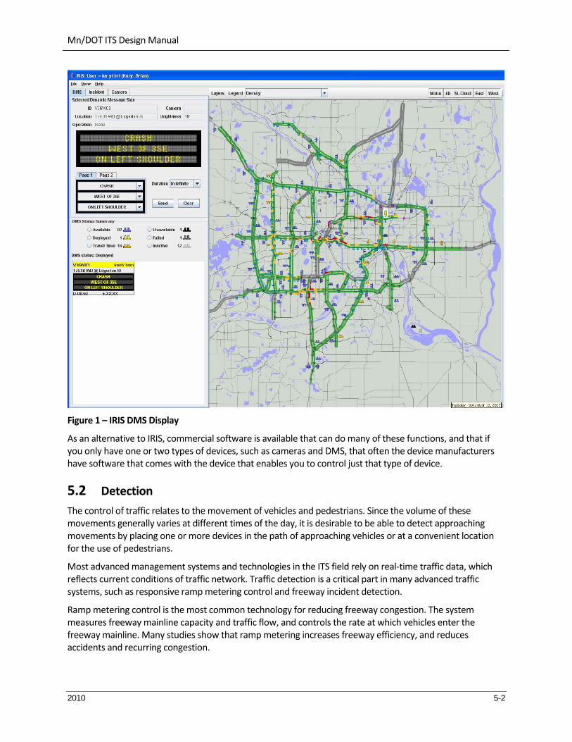
Figure 1 illustrates a screen from IRIS (DMS Control).
Mn/DOT ITS Design Manual
2010 5-2
Figure 1 – IRIS DMS Display
As an alternative to IRIS, commercial software is available that can do many of these functions, and that if you only have one or two types of devices, such as cameras and DMS, that often the device manufacturers have software that comes with the device that enables you to control just that type of device.
5.2 Detection
The control of traffic relates to the movement of vehicles and pedestrians. Since the volume of these movements generally varies at different times of the day, it is desirable to be able to detect approaching movements by placing one or more devices in the path of approaching vehicles or at a convenient location for the use of pedestrians.
Most advanced management systems and technologies in the ITS field rely on real‐time traffic data, which reflects current conditions of traffic network. Traffic detection is a critical part in many advanced traffic systems, such as responsive ramp metering control and freeway incident detection.
Ramp metering control is the most common technology for reducing freeway congestion. The system measures freeway mainline capacity and traffic flow, and controls the rate at which vehicles enter the freeway mainline. Many studies show that ramp metering increases freeway efficiency, and reduces accidents and recurring congestion.

Mn/DOT ITS Design Manual
2010 5-3
In freeway incident management systems, detectors generally are used to detect two types of congestion: recurring and nonrecurring. Recurring congestion is predictable at specific locations and times. Nonrecurring congestion is caused by random, temporary incidents, such as accidents and other unpredictable events.
Traffic detector technologies are continuously incorporated into new ITS application fields. For example, a portable intelligent transportation system provides traveler information in specific sites to improve safety and operation in work zones. A computerized control system integrates detector (speed sensor) and traveler information dissemination technologies. The control system automatically determines appropriate responses according to current traffic conditions.
Traffic detection systems play important roles not only in traditional transportation management but also in advanced transportation management systems. Traffic detection systems provide data to meet different needs in transportation fields.
5.2.1 Types of Detection
The different types of vehicle detectors available include but are not limited to the following types.
Intrusive Detection (in‐roadway)
o Inductive loop detects a change in resonant frequency by the introduction of a metal in the magnetic field of the detection zone.
o Magnetic/Magnetometer detects moving ferrous metal objects – pulse.
o Microloop detects a change by moving metal in the earth’s magnetic field – pulse. Small inductive loop placed on top of a magnetometer.
Non‐Intrusive Detection (above roadway or sidefire)
o Photo electric/Infrared detects a break in a beam of light – presence or pulse.
o Radar/Microwave detects moving objects by sending and receiving electronic pulses – pulse.
o Ultrasonic detects sound with a microphone – presence or pulse.
o Video detects a change in a video pixel range – presence or pulse.
Non‐intrusive detector technologies include active and passive infrared, microwave radar, ultrasonic, passive acoustic, and video image processing. Active infrared, microwave radar, and ultrasonic are active detectors that transmit wave energy toward a target and measure the reflected wave. Passive infrared, passive acoustic, and video image processing are passive detectors that measure the energy emitted by a target or the image of the detection zone.
Some detectors record vehicles whether stopped or in motion. Others require that the vehicle be moving at a speed of at least 2 or 3 mph.
Normal loop or magnetic detectors will operate in either the pulse mode or presence mode. The magnetic detector produces a short output pulse when detection occurs, no matter how long the vehicle remains in the detection area. The normal loop is intended to produce a detector output for as long as a vehicle is in the field of detection.
Examples of controller functionality are; locking memory, non‐lock, delay call, extend (stretch) call, and stop bar.

Mn/DOT ITS Design Manual
2010 5-4
Another type of detection is the “speed analysis system”. This system is a hardware assembly composed of two loop detectors and auxiliary logic. The two loops are installed in the same lane a precise distance apart. A vehicle passing over the loops produces two actuations. The time interval between the first and the second actuation is measured to determine vehicle speed.
5.2.2 Inductive Loop Detectors
The most common type of vehicle detection device in use today is the inductive loop. This is a loop of wire imbedded in the pavement (saw cut in existing concrete or NMC loop in new concrete) carrying a small electrical current. When a large mass of metal passes over the loop, the magnetic field is disturbed and generates, or induces, a change in resonant frequency in the wire. This change in frequency is then recognized by the detector amplifier and signals the controller that a vehicle is present.
5.2.3 Video Detectors
Vehicle detection by video cameras is one of the most promising new technologies for non‐intrusive large‐scale data collection and implementation of advanced traffic control and management schemes. This concept provides real‐time vehicle detection and traffic parameter extraction from images generated by video cameras. Major worldwide efforts have been directed at development of a practical device for image processing.
A video image processing system typically consists of the following components:
Image hardware ‐ The imaging sensor is an electronic camera (conventional TV camera or an infrared camera) that overlooks a section of the roadway and provides the desired image information.
Processor ‐ A processor determines vehicle presence or passage from images received by the camera. It also provides other traffic parameters preferably in real‐time.
Software ‐ Advanced tracking system software performs operations, detector programming, viewing of vehicle detections, and roadway surveillance.
Image processing detection systems can detect traffic in many locations (i.e., multiple spots) within the camera's field of view. These locations can be specified by the user in minutes using interactive graphics, and can be changed as often as desired. This flexible detection is achieved by placing detection lines along or across roadway lanes on a TV monitor displaying the traffic scene (not physically placed in the pavement). Each time a vehicle image crosses these lines, a detection signal (presence or passage) is generated. The result is similar to that produced by loop detectors.
VIDS are advantageous in traffic detection since:
They are mounted above the road rather than in the road, providing multi‐lane coverage along with installation and servicing advantages of traffic flow maintenance and personnel safety during detector repair.
Placement of vehicle detection zones on the road is not limited to a particular detection configuration. The configuration can be controlled and adjusted manually (by an operator with a computer terminal) or dynamically (by software) at any time, as a function of traffic flow.
The shape of the detection zone can be programmed for specific applications, such as freeway incident detection, detection of queue lengths (that cannot easily or economically be derived by conventional devices) and detection of turning patterns.

Mn/DOT ITS Design Manual
2010 5-5
5.2.4 Radar/Microwave Detectors
Development of microwave radar during World War II enabled this technology to be applied to detection of vehicular traffic. The principles of operation involve microwave energy being beamed on an area of roadway from an overhead antenna, and the vehicle's effect on the energy detected. The antennas capture a portion of the transmitted energy reflected toward them by objects in the field of view. By direct comparison of transmitted energy with reflected energy from a moving vehicle, a Doppler beat note can be detected which in turn can be used to operate an output device. Use of continuous wave (CW) transmission and reliance on the use of a Doppler signal from the return wave eliminates the need for any gating or distance measurement, and, thereby, provides a simple detector responsive to vehicles moving through the field. By appropriate processing of information in the received energy, direct measurements of vehicle presence, occupancy, and speed can be obtained.
Mention the difference between Doppler and other kinds of radar. Doppler only detects motion. I don’t know what you call the other types of radar, but they can measure stationary objects.

Mn/DOT ITS Design Manual
2010 5-1
5.2.5 Detector Technology Strengths and Weaknesses
Table 3 – Detector Technology Strengths and Weaknesses
[Source: FHWA Traffic Detector Handbook]
Technology Strengths Weaknesses Volume Presence Speed Classification
Inductive loop
Flexible design to satisfy large variety of applications.
Mature, well understood technology.
Large experience base.
Provides basic traffic parameters (e.g., volume, presence, occupancy, speed, headway, and gap).
Insensitive to inclement weather such as rain, fog, and snow.
Provides best accuracy for count data as compared with other commonly used techniques.
Common standard for obtaining accurate occupancy measurements.
High frequency excitation models provide classification data.
Installation requires pavement cut.
Improper installation decreases pavement life.
Installation and maintenance require lane closure.
Wire loops subject to stresses of traffic and temperature.
Multiple loops usually required to monitor a location.
Detection accuracy may decrease when design requires detection of a large variety of vehicle classes.
Yes Yes Yes Yes
Indicate if by length or axles

Mn/DOT ITS Design Manual
2010 5-2
Technology Strengths Weaknesses Volume Presence Speed Classification
Magnetometer (two‐axis fluxgate magnetometer)
Less susceptible than loops to stresses of traffic.
Insensitive to inclement weather such as snow, rain, and fog.
Some models transmit data over wireless radio frequency (RF) link.
Installation requires pavement cut.
Improper installation decreases pavement life.
Installation and maintenance require lane closure.
Models with small detection zones require multiple units for full lane detection.
Magnetic (induction or search coil magnetometer)
Can be used where loops are not feasible (e.g., bridge decks).
Some models are installed under roadway without need for pavement cuts. However, boring under roadway is required.
Insensitive to inclement weather such as snow, rain, and fog.
Less susceptible than loops to stresses of traffic.
Installation requires pavement cut or boring under roadway.
Cannot detect stopped vehicles unless special sensor layouts and signal processing software are used.
Microwave radar
Typically insensitive to inclement weather at the relatively short ranges encountered in traffic management applications.
Direct measurement of speed.
Multiple lane operation available.
Continuous wave (CW) Doppler sensors cannot detect stopped vehicles

Mn/DOT ITS Design Manual
2010 5-3
Technology Strengths Weaknesses Volume Presence Speed Classification
Active infrared (laser radar)
Transmits multiple beams for accurate measurement of vehicle position, speed, and class.
Multiple lane operation available.
Operation may be affected by fog when visibility is less than 20 feet (ft) (6 m) or blowing snow is present.
Installation and maintenance, including periodic lens cleaning, require lane closure
Passive infrared Multizone passive sensors measure speed.
Passive sensor may have reduced vehicle sensitivity in heavy rain, snow and dense fog.
Some models not recommended for presence detection.
Ultrasonic
Multiple lane operation available
Capable of overheight vehicle detection.
Large Japanese experience base.
Environmental conditions such as temperature change and extreme air turbulence can affect performance. Temperature compensation is built into some models.
Large pulse repetition periods may degrade occupancy measurement on freeways with vehicles traveling at moderate to high speeds.
Acoustic
Passive detection.
Insensitive to precipitation.
Multiple lane operation available in
Cold temperatures may affect vehicle count accuracy.
Specific models are not recommended with slow‐moving

Mn/DOT ITS Design Manual
2010 5-4
Technology Strengths Weaknesses Volume Presence Speed Classification
some models. vehicles in stop‐and‐go traffic.
Video image processor
Monitors multiple lanes and multiple detection zones/lane.
Easy to add and modify detection zones.
Rich array of data available.
Provides wide‐area detection when information gathered at one camera location can be linked to another.
Installation and maintenance, including periodic lens cleaning, require lane closure when camera is mounted over roadway (lane closure may not be required when camera is mounted at side of roadway).
Performance affected by inclement weather such as fog, rain, and snow; vehicle shadows; vehicle projection into adjacent lanes; occlusion; day‐to‐night transition; vehicle/road contrast; and water, salt grime, icicles, and cobwebs on camera lens.
Reliable nighttime signal actuation requires street lighting.
Requires 30‐ to 50‐ft (9‐ to 15‐m) camera mounting height (in a side‐mounting configuration) for optimum presence detection and speed measurement.
Some models susceptible to camera motion caused by strong winds or vibration of camera mounting structure.
Generally cost effective when

Mn/DOT ITS Design Manual
2010 5-5
Technology Strengths Weaknesses Volume Presence Speed Classification
many detection zones within the camera field of view or specialized data are required.

Mn/DOT ITS Design Manual
2010 5-1
5.2.6 Vehicle Classification
Newer inductive‐loop detector electronics units and loop configurations are capable of vehicle classification. The electronics module uses artificial neural network software to classify the traffic stream into the 23 categories depicted in Figure 2. The first 13 are the standard FHWA classes, while the remaining ones represent vehicles with unique characteristics.
Figure 2 – Classes available from inductive‐loop classifying sensor

Mn/DOT ITS Design Manual
2010 5-2
Classification by axles:
Axle‐based classification can include both the number of axles per‐vehicle as well as axle spacing for each vehicle. The FHWA has defined 13 vehicle classes based on axle configurations, see Table 3. This vehicle classification scheme is generally followed and will be used for analysis in this evaluation.
Data from the piezoelectric sensors and loop detectors will be sent to an automatic data recorder (ADR) to combine and collect per‐vehicle axle‐based classification. The final result will be an accurate baseline measure of distance between each set of axles for each vehicle.
FHWA Vehicle Classification
Class
Bin
No. of
Axles Vehicle Description Notes
1 2 Motorcycles
2 2 Passenger Vehicles Sedans, coupes and station wagons
3 2 Other 2‐axle, four tire single unit vehicles Includes pickups, vans, campers, etc.
4 2 or more Buses Includes only traditional buses
5 2 2‐Axle, 6‐Tire, Single Unit Trucks
6 3 3‐Axle Single Unit Trucks
7 4 or more 4‐Axle Single Unit Trucks
8 3,4 4 or fewer Axle Single‐Trailer Trucks Semi with trailer
9 5 5‐Axle Single‐Trailer Trucks
10 6 or more 6 or more Axle Single‐Trailer Trucks
11 4,5 5 or fewer Axle Multi‐Trailer Trucks
12 6 6‐Axle Multi‐Trailer Trucks
13 7 or more 7 or more Axle Twin Trailer Semi Trucks
Classification by Length:
Although the axle‐based classification system is used by many agencies, the FHWA does not require each state agency to use this system. Each state agency is allowed to develop its own classification system to suit its own needs. Some states are moving towards length‐based detection. Because there is not yet a standard method to classify vehicles by length, a number of different agencies have recommended schemes. It is common to aggregate data into three to five length‐based bins. The proposed length‐based classification scheme is in Table 4. The table also maps the length bins to FHWA classes. These bins were determined based on a survey of multiple states and a 2005 Mn/DOT study that recommended the use of these bins. A per‐vehicle analysis of length will be done for each sensor which can then be aggregated into any set of length‐based bins.

Mn/DOT ITS Design Manual
2010 5-3
Proposed Vehicle Length-based Classifications
Vehicle Class Vehicle Length Vehicle Class Axle to length adjustment
Motorcycle 0 to 7ft 1 0 ft
Passenger Vehicles (PV) 7 to 22 ft 2, 3 2.6 ft
Single Unit Truck (SU) 22 to 37 ft 4,5,6 12.8 ft
Combination Trucks (MU) Over 37 ft 7‐13 3.4 ft
One possible method for a length‐based detection baseline is to use loop detectors. A study conducted for the Florida DOT compared loop‐measured length with manually‐measured length. The study found an average length difference for each FHWA vehicle class measured by these two methods. This information can be applied to determine appropriate adjustments for each length‐based bin. For the upcoming evaluation period, a modification can be made to loop system determined vehicle length to appropriately apply an adjustment to determine vehicle length. A preliminary estimate is shown in the right column of Table 4. These numbers will be refined when the mix of traffic at the NIT Test Site is known and more information about the Florida study is known.
A second possible baseline for length‐based classification is to use piezoelectric sensors to determine the length between each axle of a given vehicle. A modification will be made to apply an adjustment to the length between the front and rear axle to determine vehicle length. The estimator value will be different for each FHWA classification. Project team members will determine these estimator values for each classification by measuring difference in axle length and total length of 10‐20 vehicles in each class and then determining the average difference, which will be the estimator value for that class.
5.2.7 Speed Monitoring
5.2.8 Wrong‐Way Detection
An important area of concern relative to highway safety is the occurrence or drivers going the wrong way on one‐way streets, highway mainline lanes, or highway entry or exit ramps. Along with significant signing, various monitoring approaches have been tried and implemented to provide immediate detection of vehicles going the "Wrong Way". To date, systems using magnetic induction loops represent the most common solution for "Wrong Way" detection. Two or more loops are placed in the roadway as shown in Figure 3. Relative to the correct direction of travel, loop #1 is the upstream vehicle detection sensor and loop # 2 is the downstream vehicle detection sensor. In the presence of traffic, vehicle detection at loop # 1 followed by detection at loop #2 indicates the correct direction of travel by the detected vehicle. Vehicle detection at loop #2 followed by detection at loop #1 indicates the incorrect direction of travel by the detected vehicle. When properly installed and maintained, the loop‐based system performance should be reasonable.

Mn/DOT ITS Design Manual
2010 5-4
Figure 3 – Loop Based Wrong Way Detection
5.2.9 Detection Area Discussion
5.2.10 Setup vs. Design Parameters
5.3 Closed Circuit Television (CCTV)
CCTV shall mean a video or still picture camera system used to collect images and relay images to a central monitoring location, and project images onto a video monitor, television screen, Internet display, or other monitoring equipment.
Closed circuit television (CCTV) cameras are a key part of traffic management systems. The primary benefit of CCTV is the ability to provide visual information required to make informed decisions. CCTV cameras are used for roadway surveillance, verification of incidents detected by other means (e.g., cellular calls, speed detectors, etc.), and for assistance in determining appropriate responses to an unplanned event or incident. Beyond these tasks, cameras can be utilized for:
Monitoring traffic movements on the mainline and ramps.
Variable Message Sign verification.
Verification of stranded motorists and incidents.
Observing localized weather and other hazardous conditions.
5.3.1 The Camera System
The camera system is a suite of components which work together to create a seamless video unit. The camera system is capable of acquiring traffic video, digitizing and transmitting the resulting data into a network infrastructure, and receiving and reacting to commands with feedback to the controlling system. Each camera site contains a full camera system and is strategically located adjacent to a route to best acquire traffic video. The video system consist of a camera, pan‐tilt‐zoom (PTZ) assembly and camera control receiver (CCR.
Both analog and digital cameras are marketed for freeway management application, as summarized below:
Analog. The main component for analog cameras is the Charge Coupled Device (CCD) sensor. The CCD sensor is a solid‐state imaging technology available in a compact, inexpensive format. CCD

Mn/DOT ITS Design Manual
2010 5-5
cameras are typically available in a variety of imager size formats, including 2/3", 1/2", 1/3" and ¼". The two most common, proven CCTV camera sensors are the interline transfer and frame transfer CCDs. Both CCD devices provide good quality video and good sensitivity.
Interline CCD is the most commonly used system type for security and surveillance applications in traffic management, mass transit, airports, and military applications. Interline CCD sensors are smaller than frame transfer imagers, have longer service life, require less periodic maintenance, produce no geometric distortion, are immune to vibration, magnetic fields and direct exposure to sunlight or headlight, and consume minimal power. The interline transfer CCD image device eliminates overload streaking because it is not sensitive to infra‐red, improves dynamic range, and also provides high resolution.
The frame transfer CCD imaging device provides extraordinary resolution, and is very well suited to full‐motion video monitoring under consistent illumination levels. However, the frame transfer device uses larger individual photocells and is thus more sensitive. The frame transfer device requires a larger chip area, so it costs more and has a higher level of "smear" than interline transfer devices. Smear occurs when an illumination source overloads the imager, resulting in the appearance of bright vertical lines on the image. Both types of CCD devices have some smear, but it is more pronounced in the frame transfer device.
Digital.
Replace above with discussion on digital video encoding, compression, digital transmission, etc.

Mn/DOT ITS Design Manual
2010 5-6
Figure 4 – CCTV Pole Installation Detail
Night time consideration – Infra Red IR filters, etc.

Mn/DOT ITS Design Manual
2010 5-7
MnDOT TMC does not use domes anymore – icing, other.
5.3.2 CCTV Mounting
For fixed location CCTV systems, video cameras are permanently mounted either on existing structures along the freeway or on specially installed camera poles (see Figure 15‐10).
5.3.2.1 Mounting Heights
5.3.2.2 Field of View
5.3.2.3 Crankdown Pole
5.3.2.4 Required Windloads
5.3.2.5 Existing Structures
5.3.3 Performance and Bandwidth
Integration – addressing, transmition, etc.
This is an issue if you do not have a high bandwidth connection to the camera. For example, in some remote rural areas the camera may be using a wireless link with much less bandwidth than a fiber optic connection. In cases of limited bandwidth, you have to trade off things like camera resolution, refresh rate, and compression losses. You have to design the communication system to effectively allow access to the video minimizing bottleneck links. Performance also affects camera control. In a low bandwidth situation, there is a delay between issuing the camera movement command and when you actually see the camera moving, which makes it difficult to point the camera where desired. In these situation you may want to make sure that the camera control includes the ability to use presets so that the operator can easily point the camera in the desired direction.
5.3.4 Camera Control
Using a pan/tilt (P/T) platform, CCTV system operators can change camera position about the 360‐degree "azimuth" axis, and adjust camera elevation up or down (within a 90 degree range). Together with a zoom lens, the P/T allows operators to view a scene within any direction about the camera, and within the lens field‐of‐view and distance ranges.
discussion about considerations of degrees of rotation, pan/tilt rates, etc., without actually giving the numbers
5.3.5 Temporary Cameras
Portable CCTV systems can serve several purposes including the following:
Short‐term traffic monitoring in areas with non‐recurring congestion (e.g., work zone, critical incident, detours etc.).

Mn/DOT ITS Design Manual
2010 5-8
Traffic monitoring at special traffic generators (e.g., stadiums, parades, etc.).
Traffic monitoring along evacuation routes
Determination of optimum camera location for fixed location CCTV systems.
Portable CCTV systems are typically mounted in a light truck or van or on a trailer (see Figure 15‐11). Components of a portable system include the following:
Camera with pan‐tilt‐zoom capability.
Telescopic boom.
Television monitor and video recorder
Camera control unit for controlling pan, tilt, and zoom functions.
Generator for powering equipment; or battery power with solar charging
Air compressor for operating telescopic boom.
Wireless communications
5.3.6 Camera Housing
Domes, heaters, windshield washers, etc.
5.4 Dynamic Message Signs (DMS)
A dynamic‐ message sign, often abbreviated DMS, is an electronic traffic sign often used on roadways to give travelers information about special events. Such signs warn of traffic congestion, accidents, incidents, roadwork zones, or speed limits on a specific highway segment. In urban areas, DMS are used within parking guidance and information systems to guide drivers to available car parking spaces. They may also ask vehicles to take alternative routes, limit travel speed, warn of duration and location of the incidents or just inform of the traffic conditions.
A complete message on a panel generally includes a problem statement indicating incident, roadwork, stalled vehicle etc; a location statement indicating where the incident is located; an effect statement indicating lane closure, delay, etc and an action statement giving suggestion what to do traffic conditions ahead. These signs are also used for AMBER Alert messages.

Mn/DOT ITS Design Manual
2010 5-9
Figure 5 – Bridge Mounted Dynamic Message Sign
5.4.1 DMS Location and Design
The most critical locations for installing permanent DMSs are in advance of interchanges or highways where drivers have the opportunity to take some action in response to messages displayed on the sign. A DMS should not compete with existing roadway signs. At times, relocation of some static signs may be required in order to install a DMS at a critical location. In general, a DMS should be permanently installed at the following locations:
Upstream from major decision points (e.g., exit ramps, freeway‐to‐freeway interchanges, or intersection of major routes that will allow drivers to take an alternate route).
Upstream of bottlenecks, high‐accident areas, and/or major special event facilities (e.g., stadiums, convention centers).
Where regional information concerning weather conditions such as snow, ice, fog, wind, or dust is essential.
The ease with which a sign can be detected in the environment (conspicuity) and the ease with which the message can be read (legibility) will enhance the effectiveness of motorists' visibility of the CMS and its message. In addition, the manner in which the message is displayed must be considered (e.g., if the message is too luminous, it can be easily detected but difficult to read because of glare.) Factors that affect the legibility of light‐emitting CMSs include the character height; font style; character width (spacing and size of pixels); spacing of characters, words and lines; size of sign borders; and contrast ratio.

Mn/DOT ITS Design Manual
2010 5-10
The DMS designer and operator need to know about the actual site characteristics in the vicinity of the DMS. These characteristics dictate the amount of information that can be displayed. Among the items of interest are the following:
The operating speed of traffic on the roadway;
The presence and design characteristics of any vertical curves affecting sight distance;
The presence of horizontal curves and obstructions such as trees, bridge abutments, or construction vehicles that constrain sight distance to the CMS around the curve;
The location of the CMS relative to the position of the sun (for daytime conditions);
The presence, number, and information on static guide signs in the vicinity; and
Whether or not rain or fog is present to degrade visibility to the sign.
Other design considerations include: sign size (which affects message length as well as support structure requirements), maintenance access (e.g., walk‐in housings, front access), technology, viewing angle and distance, character size, and sign position relative to sun during various times of day and days of the year.
As discussed later, the maximum length of a message that should be displayed is primarily dictated by the amount of information drivers can read and comprehend during the period when they are within the legibility distance of the DMS. The maximum length of a DMS message is also controlled by the characteristics of the sign. These include the type of sign (LED, fiberoptic, etc.), the number of lines available, and the number of characters on each line. Each of these characteristics can have an effect on how far away the DMS can be read and, consequently, how much information can be presented to motorists. It should be the responsibility of the TMC manager/supervisor to assess the DMS characteristics and determine the maximum length of message to display.
5.4.2 Sign Types
Most signs are based on Light Emitting Diode (LED) technology. LEDs are low power and last for a long time. Some signs can be supplemented with flashing beacons. Many signs have photocells to sense the ambient lighting conditions and adjust the brightness of the display automatically. Some signs have environmental controls in their housing, such as ventilation fans and potentially heaters. Some signs can incorporate locally generated data into the centrally controlled message, such as including the time, temperature, or speed of closest vehicle into the message on the sign. Many signs have built‐in diagnostics that can notify an operations center upon failure of pixels, modules, communications, environmental controls, etc.
5.4.2.1 Overhead Mount vs. Roadside Mount
If you have more than 2 lanes per direction of traffic, or heavy traffic with 2 lanes per direction, the overhead mount is beneficial so that other traffic does not block the driver’s view of the sign. For 2 lane roads (one lane per direction), or for 4 lane roads with light traffic, a roadside mounted sign may be acceptable and will probably be less expensive.
5.4.2.2 Sign Characteristics
DMS can be character based, line matrix, or full matrix. A character based sign has a defined set of characters and can display one character per position on the sign. These signs cannot do graphics. A line matrix sign considers each line of the sign as a grid of pixels, and can display any combination of pixels on the line. This allows different fonts for text and allows for graphics. A full matrix sign considers the whole sign as

Mn/DOT ITS Design Manual
2010 5-11
one big matrix of pixels which can be controlled in any combination. This allows for even more advanced fonts, such as fonts taller than a single line of the sign, and allows for graphics.
5.4.2.3 Pixel Colors
Many signs have amber pixels on a black background. The MN MUTCD recommends that the color be suitable for the type of message, such as white on black for regulatory, yellow on black for warning, etc., but allows using amber for everything. High definition full color matrix signs are full matrix signs with closely spaced pixels that can be any color. This allows close replication of standard sign elements, such as an Interstate freeway route shield. Although they are capable of displaying photos and moving images, these should not be used in the highway environment.
5.4.3 Sign Control
Sign control allows an operator to select a message for display on a sign and to monitor and adjust other sign parameters. Sign control may be provided locally at the sign location itself or remotely from a center. Portable Changeable Message Signs mounted on a trailer for temporary use are a common application for local sign control, such as in a work zone. A permanently mounted DMS will normal provide for remote control of the sign. The operator will want to be able to remotely determine what message is currently displayed on the sign, to put new messages on the sign, to blank out the sign, and to obtain diagnostic information on the condition of the sign. Sign control may allow an operator to adjust parameters such as brightness, temperature for cooling fans to turn on, etc.
5.5 Ramp Meters
In twin cities, everything is centrally controlled. Does have TOD, DOW. Define traffic responsive.
Signal head and mountings – materials are important. Away from painted poles, etc.
Dynamic warning flashers – for ramp meters. Warning go to have to stop.
Ramp Meters are traffic signals on highway entrance ramps, and they are designed to:
Reduce crashes
Reduce congestion
Provide more reliable travel times
Mn/DOT Goals for Ramp Meters:
Ramp meter waits will be no more than four minutes per vehicle on local ramps and two minutes per vehicle on freeway‐to‐freeway ramps.
Vehicles waiting at meters will not back up onto adjacent roadways
Meter operation will respond to congestion and operate only when needed.
5.5.1 Signal Heads and Mounting
Figure 6 illustrates a one‐way ramp control detail.

Mn/DOT ITS Design Manual
2010 5-12
Figure 6 – Ramp Meter (One‐Way) Detail
5.5.2 Control Cables

Mn/DOT ITS Design Manual
2010 5-13
5.6 RWIS
A road weather information system (RWIS) is a combination of technologies that collects, transmits and disseminates weather and road condition information. The component of an RWIS that collects weather data is the environmental sensor station (ESS). An ESS is a fixed roadway location with one or more sensors measuring atmospheric, surface (i.e., pavement and soil), and/or hydrologic (i.e., water level) conditions including:
Atmospheric sensors – air temperature, barometric pressure, relative humidity, wind speed and direction, precipitation type and rate, visibility distance
Surface sensors – pavement temperature and condition (dry, wet, ice, freeze point, chemical concentration), subsurface temperature, subsurface freeze/thaw cycles)
Hydrologic sensors (stream, river and tide levels)
Data collected from environmental sensors in the field are stored onsite in a Remote Processing Unit (RPU) located in a cabinet. In addition to the RPU, cabinets typically house power supply and battery back‐up devices. The RPU transmits environmental data to a central location via a communication system. Central RWIS hardware and software collect field data from numerous ESS, process data to support various operational applications, and display or disseminate road weather data in a format that can be easily interpreted by a user. Environmental data may be integrated into automated motorist warning systems, and transmitted to TMCs, emergency operations centers and maintenance facilities for decision support. This information may also be used to enhance forecasts and supplement mesoscale environmental monitoring networks (i.e., mesonets)
Weather service providers (who are often RWIS/ESS vendors) also use the data to develop tailored weather services and products, including pavement temperature / bridge icing forecasts, ice and snow prediction, optimization of treatment routes and resource allocation, and thermal mapping. The latter is a process to quantify the variation in nighttime road surface temperatures across the roadway network. This variation can be 10°F or greater (depending on exposure, altitude, traffic, and road materials), which can impact which areas may become icy before others.
Transportation managers utilize environmental data to implement three types of road weather management strategies – advisory, control and treatment. Advisory strategies provide information on prevailing and predicted conditions to both transportation managers and motorists. Control strategies alter the state of roadway devices to permit or restrict traffic flow and regulate roadway capacity. Treatment strategies supply resources to roadways to minimize or eliminate weather impacts. Many treatment strategies involve coordination of traffic, maintenance, and emergency management agencies. Winter maintenance managers utilize road weather information to assess the nature and magnitude of threats, make staffing decisions, plan treatment strategies, minimize costs (i.e., labor, equipment, materials), and assess the effectiveness of treatment activities (by agency staff or subcontractors). Traffic managers may alter ramp metering rates, modify incident detection algorithms, vary speed limits, restrict access to designated routes, lanes or vehicle types (e.g., tractor‐trailers) and disseminate road weather information to motorists in order to influence their travel decisions. Some Traffic Management Centers integrate weather data with traffic monitoring and control software. Emergency managers may employ decision support systems that integrate weather observations and forecasts with population data, topographic data, as well as road network and traffic data. When faced with flooding, tornadoes, hurricanes, or wild fires; emergency managers may use this data to evacuate vulnerable residents, close threatened roadways and bridges, and disseminate information to the public.

Mn/DOT ITS Design Manual
2010 5-14
5.7 Dynamic Warning Flashers
Don’t have flasher cabinets.
Examples could include a “crossing traffic ahead” sign activated by a detector at a stop line on a stop controlled approach, a curve warning flasher that activates if a vehicle is approaching a curve above a certain speed threshold, an overheight detector with a warning flasher, a fog warning with flasher, an activated animal warning system (deer crossing), etc. In all the cases, there is some means of detection that then activates a flasher on a warning sign. These would normally have the sign mounted to a traffic signal pedestal with breakaway base and a flasher on top or wig‐wag flashers on either side of the diamond shaped warning sign.
Configuration should not mount a heavy cabinet on the side of the pedestal pole where it could be a problem if the pole gets hit.
5.7.1 Flashing Beacons
The flashers for a dynamic warning flasher should be standard LED signal sections, red or yellow as appropriate, 8 inch or 12 inch as appropriate. Yellow beacons are required for use with warning signs. A red beacon is used with a STOP sign. Single beacons on a high speed road should be 12 inch. Beacons on a low speed road or used as a pair in a wig‐wag configuration should be 8 inch. All beacons should have background shields. As per the MN MUTCD, the beacon should be mounted at least 12 inches from the edge of the sign.
5.7.2 Flasher Cabinet
When the flasher pedestal is located on a high speed road using breakaway mounting, the flasher cabinet should not normally be mounted to the pedestal, as it could come off on impact and become a projectile. A separate cabinet mounted outside the clear zone can house the flasher, circuit breaker, any sensor electronics used to activate the flasher, and any control or communications equipment.
5.7.3 Activation
Depending upon the application, the flasher may be activated by a sensor and/or a controller. Sensors may include speed sensors, vehicle presence sensors, or height sensors, for example.
5.8 Highway Advisory Radio (HAR)
Highway Advisory Radio (HAR) refers to low power AM or FM radio transmissions where localized information is broadcast and travelers are alerted to the presence of the broadcast using static or dynamic signs. The localized transmissions may cover areas that range from 5 miles to 30 miles depending upon the terrain and technologies used. The radio transmissions may be either at fixed permanent locations or mobile devices that may be temporarily located and moved as needed.
5.8.1 Field System
The transmitters and other broadcast components are located in the field. There are multiple technologies available for HAR application.

Mn/DOT ITS Design Manual
2010 5-15
5.8.1.1 10‐Watt AM Transmission (FCC Licensed)
This is the most common HAR application. When properly maintained and installed, 10‐watt transmitters have a broadcast radius of approximately 3–5 miles depending on topography, atmospheric conditions, and the time of day. Frequencies used are generally located at the extreme ends of the AM band using specific frequencies based upon the availability of "holes" in the spectrum left by government and commercial stations. New FCC rules permit HAR to be broadcast on any frequency between 530 kHz and 1710 kHz provided an FCC license is obtained. The FCC rulings have also opened up the former dedicated HAR frequencies, 530 kHz and 1610 kHz, to commercial broadcasting, thereby increasing the potential for interference or possibly the loss of a license.
The characteristics of the broadcast are also affected by the frequency used. The lower ranges of the band (e.g., 530 kHz) are adversely affected by power lines (because of its long wavelength). It also has problems with signal fade, which causes distorted transmission for a reasonable distance along the outer (fringe) areas of the coverage area. Because of this, it is uncommon to find any commercial broadcasters on this end, which is an advantage. On the other end of the spectrum, power lines have less impact on the signal, and a crisper fringe transmission.
5.8.1.2 Digital Highway Advisory Radio
Digital HAR eliminates many limitations of traditional dial‐up systems, and improve quality of messages being broadcast to the traveling public. While dial‐up systems typically operate over analog phone lines, advanced computer‐controlled systems use digital signal processing to optimize performance.
Compared to traditional dial‐up systems, "digital HAR" offers increased speed of message updating, centralized management of multiple stations, enhanced reliability, superior audio quality, ease of operation, and automated event logging. The time required for an operator to update audio at a remote site from the central control unit can be as little as two seconds. This can be accomplished through a simple "drag & drop" operation using a specialized Windows program. A Windows environment also easily allows for control of multiple HAR stations from a single central location.
Digital control provides closed loop operation assuring that messages and commands are received exactly as downloaded. There is no guessing about what is occurring at the remote sites. Analog phone lines typically limit audio bandwidth to about 2.5 kHz reducing the quality of the audio motorists receive on their vehicle radios. If desired, digital messages can be downloaded to remote HAR sites at CD quality provided that FCC imposed bandwidth limitations are satisfied.
5.8.1.3 Low‐Power AM Transmission (No FCC License Required)
Low‐power HAR has been developed as a means of tightly controlling the broadcast zone and thereby limiting interference from adjacent zones. Low power HAR differs from the previously discussed 10‐watt HAR in that its broadcast radius (per transmitter) is generally limited to 500 feet to 1500 feet. By FCC regulation, each transmitter is limited to a maximum 0.1 watt power input to the final frequency stage, and the total length of the transmission line, antenna, and ground lead can not exceed 3 meters. Whereas this limits its broadcast range, it also provides for a reasonably well‐defined area of influence, which, through an inter‐connection and synchronizing process, permits upwards of 100 transmitters to be coordinated into larger and well‐defined saturation zones. Once a car leaves this broadcast area, the signal quality becomes too weak to be heard. This permits a second zonal configuration to be established nearby, transmitting a different message on the same frequency.
Mn/DOT ITS Design Manual
2010 5-16
By using this concept, a series of zones all operating on the same frequency, may be established whereby unique site‐specific messages may be transmitted to provide condition updates in advance of decision points. Aside from the flexibility provided in establishing multiple message zones, low‐power HAR may also broadcast over any available AM radio frequency without the need to obtain additional FCC licensing approval. Though the ability to install a system without FCC approval provides the user with great flexibility in installing a system wherever desired, there is no guarantee that once installed, it will not be interfered with by some future more powerful transmission.
The relatively low signal strength must compete with a variety of obstacles, including overpowering commercial broadcasts, signal skip (particularly at night), and poor signal propagation. These difficulties can be overcome by saturating an area (zone) with multiple transmitters and synchronizing their broadcasts. However, this concept is relatively new and, very expensive as the number of transmitters required is large.
5.8.1.4 Low‐Power FM Transmission (FCC License Required)
LPFM service is available to noncommercial educational entities and Travelers' Information Station entities, but not commercial operations or individuals. Maximum effective radiated power for these stations is 100 watts, and the LPFM stations will not be protected from interference caused by full service stations that make changes to their operations. A construction permit or license is required before construction or operation of a LPFM station can be initiated.
Low‐power 100‐watt FM transmitters, when installed properly, have a broadcast radius of approximately 3‐5 miles depending on topography and atmospheric conditions. 10‐watt transmitters have an effective range of 1‐2 miles in radius. At present, LPFM licenses are not being issued for HAR. The FCC only opened the application process for frequencies for a short time period. The FCC is non‐committal about if and when this technology will again be available for HAR.
5.9 Electrically Operated Gates?
Interstate and non‐interstate – snow and ice closures
394 gate for reversible HOV
At transit stations
Discuss battery backups.
5.10 Intelligent Work Zones?
5.10.1 [Incorporate IWZ Toolbox stuff here]
The following handout is from:
http://www.dot.state.mn.us/trafficeng/workzone/iwz/MN‐IWZToolbox.pdf

Mn/DOT ITS Design Manual
2010 5-17
5.11 Control Cabinets Mn/DOT has several types of cabinet in common use. Traffic signals use a large “R” size or smaller “P” size cabinet. The RTMC uses Type 332 cabinets based on a CalTrans design. The RTMC also has a standard CCTV control cabinet. DMS controllers and ramp meter controllers are housed in the Type 332 cabinets. The Type 332 cabinet provides 19 inch rack mounting, which works well with a lot of equipment that is used in ITS.
5.12 Power Most ITS systems currently operate on 120 Volts AC with a power drop from the local utility company. Some systems operate using a low voltage DC power source, facilitating battery and solar power options.
Discussion on picking the right power. Is solar applicable, or can you pull a wire?
Each power company has different requirements. Some will go into cabinet, others won’t.
Power company agreements?
For power and communications, hardwired is best if it is feasible.
5.12.1 Service Cabinets for Utility Power The traffic signal service cabinet is an option for ITS systems. It has the option of adding battery backup. Large DMSs may require a higher capacity cabinet. The RTMC uses a smaller service cabinet that would cost less, without the battery backup option. For simple systems with modest power requirements, a simple meter and load center can be mounted on a pole.
5.12.2 Grounding and Surge Suppression ITS systems usually include sensitive electronics located in an outdoor environment and mounted on metal poles. A lightning storm can cause the equipment to fail if it is not properly protected. Every control cabinet should have a quality properly rated solid state surge suppression device located where the power conductors terminate in the cabinet. In addition to the grounding required by the National Electrical Code at the service cabinet, the control cabinet should also have a grounding conductor going from its ground bus to a ground rod. The ground rod may be the one used by the service cabinet or a different one if the cabinets are not co‐located. If the system includes tall mounting poles and is not connected by metal conduit, the pole installation should also include a ground rod. As per the National Electrical Code, it is essential that all metal cabinets, poles, housings, conduits, etc. all be connected together into a properly bonded and grounded system. All communications and video field cables should have surge suppression at both ends where they enter an enclosure or cabinet. Much unfortunate experience has shown that systems that are not properly grounded or protected from surges will not last long in the outdoor roadside environment.
5.12.3 Battery Backup Part of the design for an ITS system should be consideration of failure modes. Any source of power is subject to failure. Some ITS systems are not safety critical and can tolerate the occasional power outage. For safety critical systems, battery backup is an option. Battery backup can keep the system operational for a certain period of time when utility power is out. The size of the battery backup system can be calculated based on the load drawn by the system and the length of time it must run on battery power. One consideration of battery backup is that the batteries will need to be replaced periodically, maybe every 5 or 7 years, to ensure that they can still hold a charge.

Mn/DOT ITS Design Manual
2010 5-18
5.12.4 Solar/Wind Power
In remote rural areas, obtaining a utility power drop can be very expensive if there are no electrical utilities in the area. For some low‐power ITS applications, solar and/or wind power is an option. These options are also environmentally friendly. Resources are available [provide web links] to aid in designing the solar power. Factors include the amount of power the system needs, the percent of the time the system is operating (such as flashers that only flash upon certain infrequent events), the amount of time the system must operate in the absence of any sunlight, and the geographic location which affects the amount of sunlight received. It is a good idea to overdesign the solar power system with large safety margins. Experience has seen several solar powered systems whose operation was disrupted due to inadequate solar power configurations. In Minnesota in mid‐winter, hours of sunlight are limited and the cold causes the batteries to be inefficient, which makes it a challenge for solar powered systems. Wind power provides a nice complement to solar power. Cloudy times having less sunlight are often accompanied by higher winds. Wind turbines work better the higher they are mounted, and so mounting height could become a cost issue. Similar to solar power, resources are available [provide web links] to aid in designing wind powered systems. Off the shelf systems for solar and wind, including controllers, are available from multiple sources.
Underground battery boxes for solar powered systems may fill with water and be ruined.
5.13 Electronic Communications
5.13.1 Communications Standards
5.13.2 Grounding and Surge Suppression
5.13.3 Ethernet
5.13.4 Fiber Optic The RTMC had some issues with ice crush causing problems with fiber cables. Get input from them for the best installation method for fiber cable.
5.13.5 Wireless
With wireless communications you have to do a site survey to examine line of site. If the site survey is done in the winter, it may change in the spring when foliage returns to trees. Watch out for things that are likely to change in the future, like growth of trees or places where new buildings may be build in the line of site.
For power and communications, hardwired is best if it is feasible.
5.13.6 Leased Lines
5.14 New Technologies
5.14.1 Intersection Conflict Warning

Mn/DOT ITS Design Manual
2010 5-19
Cross street warning (Hennepin county ‐ DONE). $25 35k
169 and Mille Lac, mainline system. Sign on mainline warns of side street traffic entering. (DONE)
CICAS – gap rejection. Giving drivers gap information (around $130k)
(eventually need to work on warrants for the above)
Stop sign warning system. Flash stop sign when approaching sign
5.14.2 Curve Warning System
Curve speed warning is similar technology. Two projects under contract.
5.14.3 Automated Vehicle Location (AVL)
Used for more than just vehicle location.
5.14.4 Tolling – MnPass
Discussion of cost/benefit ratios
5.14.5 Wildlife crossing warning system
detection of wildlife near road. Infrared beams. Only larger animals will trigger the device. Amber beacon on deer crossing sign. Plan set exists for this. Bob W. retiring (March 2) has information on this.
5.14.6 Bridge warning height system
Bob from Mankato worked on this (get information from him)
5.14.7 Water on road system
Also in Mankato. Electronic detector senses water on road.
5.14.8 Fog warning system
5.14.9 Warning of Stopped or Slow Traffic Ahead
Jerry designed for D3. IWZ toolbox has the stopped traffic ahead information.
5.15 Experimental Technologies
Section for Permitting – crossing RRs, DNR, etc.
ROW issues.
In Pavement lights for lane lines.
5.15.1 Intelli‐Drive National proof of concept.
5.15.2 Arterial Travel Times

Mn/DOT ITS Design Manual
2010 5-20
Bluetooth, Misgen has one with Signal Systems, GPS probe data. Paul Czech – metro planning (more details on this project). Rashmi will get a summary of projects. Ultimately, work with signal opts.
http://www.dot.state.mn.us/guidestar/2006_2010/matt/MATT_Final_Report_v
7.pdf
5.15.3 Tolling Based on amount of vehicle miles traveled.
5.15.4 5.9 GHZ radio DSRC (dedicated short range communication). Might be under intelli‐drive. Cross‐cut across many technologies. High bandwidth wireless communication system.
o
o Other Notes:
Rural power issues – how to make a selection on best SOP. Solar, wind,
transformer. Inside of this analysis is the type of priority.
Some sort of discussion on central office contacts. – involve the parties
interested in the project.
http://www.dot.state.mn.us/guidestar/projects.html
Add the above discussed items to the Glossary of Terms

Mn/DOT ITS Design Manual
2010 6-1
6. SYSTEM DESIGN
6.1 Metro Design Checklist (update for this book)

Mn/DOT ITS Design Manual
2010 6-2

Mn/DOT ITS Design Manual
2010 6-3
6.2 Component Placement and Design
The purpose of this section is to present the fundamental procedures and standard practices related to the design of ITS components. This is presented in a series of design steps and the design considerations for each. First, the steps that are common to all components will be discussed. Then, the design steps that are applicable to individual components are addressed.
DESIGN STEP DESIGN CONSIDERATION
Create or Get an Accurate Drawing of the Location
Review preliminary design checklist
Retain coordinates within CADD file – NAD83 coordinate system, county specific.
Review scope of project & project kick‐off meeting info if appropriate
Request any additional survey or other information needed – obtain the field in place (FIP) files. FIP is a CADD file with physical installations and features (check on the technical definition of this)
Check sight distances
o Check cameras for blind spots. Normally 1 mile, may need to be more dense.
o Ramp control flasher considerations
o DMS based on readability – longitudianal and horizontal concerns.
Check CADD file(s) for corrupt elements
Review field review notes
Obtain field measurements as appropriate to confirm CADD file
Show inplace elements in dashed (or gray scaled) and new construction solid.
The plans and/or specs should call for GPS locating of as‐built installed equipment and underground cables to support future one‐call locating requirements, as well as containing provisions for how the contractor should mark their dig locations and what level of locating they must agree to when digging.
Keep track of budgeting – preliminary budget estimate
6.2.1 Detectors

Mn/DOT ITS Design Manual
2010 6-4
DESIGN STEP DESIGN CONSIDERATION
Locate Mainline Detectors Speed loops, distance between is very important if using 2 loops
Can get speed off of single loops
Occupancy loops
Naming of loops is very important (in class, go through an exercise on this)
Passage loop set beyond ramp meter (at least 25’)
o Information used to check how many pass meter and get to passage loop
Loop 3’ from edge of road (vary size)
Queue detector upstream of meter. Look at ADT of ramp. If backing up over this loop, then approaching the limit
Page 107, get image of of loops
Consider location for future elements. Place loops
For mainline, every half‐mile in every lane (metro), also push for loops in shoulders for bus lanes
For mainline detector, avoid in weaving areas. Get arronous counts.
For mainline detector, also avoid in areas where vehicles are slowing for merging traffic.
Including some double loops to help in calibration of single loops.
Labeling, notes on page 107 of plan set.
Numbering system comes from a database, Jessie Larson from RTMC Operation group. Number from left to right. N1, N2, etc. is for direction.
Locate Ramp Detection One per ramp with no meter, two per ramp if a meter.
Can perform continuity checks
Check pavement conditions for placement of loops
Typical project is a saw cut into concrete or level course, then overlay.
For new construction, use a Never Fail preformed loop. Stabilized loop that cannot get water in them. You can specify the size.
Do not place under a basket
Do not place above a culvert (near reinforcements).
Consider conduit runs
For passage loop on ramps, place detector beyond HOV merge back location.

Mn/DOT ITS Design Manual
2010 6-5
If one on ramp, maybe further upstream?
Check on distance of Home Runs……????
Might need to consider location of Queue detector…. If a porkchop, may have two movements feeding this.
Radar Detection In places with high merge areas, where need to count the cars
Also consider where the roadway is temporary.
Other detection technologies May or may not include info here…..
6.2.2 CCTV
DESIGN STEP DESIGN CONSIDERATION
Place CCTV Be careful where you locate field items like signs or cameras to ensure that there is a place for a service vehicle to park by the roadside and a way to use a ladder or bucket truck to get at the installed equipment.
Consider safety of maint vehicle during placement
Placed at every mile (Metro)
If on a straight stretch of road, place on every other side of the road
If curved, place on outside of curve
Check for blind spots caused by bridges/tunnels
Have on a hinged pole, ensure that camera will drop down to a workable area.
Cameras are labeled in order, start at 1, label sequential, west to east and south to north
Get number from operations center.
Place CCTV (Rural) Place on a higher location
6.2.3 DMS
DESIGN STEP DESIGN CONSIDERATION
Place DMS Be careful where you locate field items like signs or cameras to ensure that there is a place for a service vehicle to park by the roadside and a way to use a ladder or bucket truck to get at the installed equipment.
Location of DMS
Overhead for Metro
Side of road for rural

Mn/DOT ITS Design Manual
2010 6-6
Consider ROW issues
Require a platform for maintenance
DMS placed on their own structure
DMS is state furnished material
Starting to put maint. Vehicle pull‐off pad. Level, cleared of snow.
Source of Power Issues?
Cabinet next to every DMS on the side of the road.
What equipment type in the cabinet for DMS?
Unique label (V494N01, V494N02, etc). V = ?, 494 = highway, N = North (S if south, etc), 01 = unique number…. Then order sequential.
ILCS (intelligent lane control signal) above every lane
Every ½ mile
Lane control signals (LCS)
Combination static/dynamic signs
6.2.4 Control Cabinets
DESIGN STEP DESIGN CONSIDERATION
Place Ramp Meter Cabinets One per side of road?
Have unique ID per system
Place DMS Cabinets Placed on side of road behind guardrail
Place CCTV Cabinets Cabinet is place on the pole
Numbering Use the Highway ‐ Number
6.2.5 Power
6.2.5.1 Electrical Service Cabinet
DESIGN STEP DESIGN CONSIDERATION
Label with address
Separate cabinet for service?
Determine where SOP is
Perform a voltage drop calc?

Mn/DOT ITS Design Manual
2010 6-7
6.2.5.2 Power Cables
DESIGN STEP DESIGN CONSIDERATION
For power and communications, hardwired is best if it is feasible.
6.2.6 Communications
6.2.6.1 Communications Cabinet
DESIGN STEP DESIGN CONSIDERATION
Place Comunications Cabinet ??
6.2.6.2 Communications Cables
DESIGN STEP DESIGN CONSIDERATION
Fiber Optic For power and communications, hardwired is best if it is feasible.
The RTMC had some issues with ice crush causing problems with fiber cables. Get input from them for the best installation method for fiber cable.
Do not use steel conduit,
Use double jacketed, armored cable. Help to locate and
Don’t have dips so water doesn’t pond
Spacing between pull vault?
Trunk fiber vs. pigtails
Metro tries to place own fiber
Some may share with private shares
Shares with other government agencies
Maybe sharing with vaults
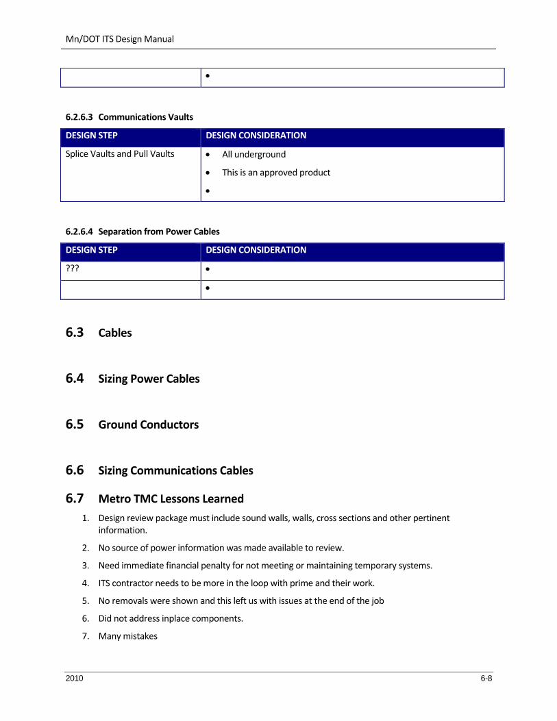
Mn/DOT ITS Design Manual
2010 6-8
6.2.6.3 Communications Vaults
DESIGN STEP DESIGN CONSIDERATION
Splice Vaults and Pull Vaults All underground
This is an approved product
6.2.6.4 Separation from Power Cables
DESIGN STEP DESIGN CONSIDERATION
???
6.3 Cables
6.4 Sizing Power Cables
6.5 Ground Conductors
6.6 Sizing Communications Cables
6.7 Metro TMC Lessons Learned
1. Design review package must include sound walls, walls, cross sections and other pertinent information.
2. No source of power information was made available to review.
3. Need immediate financial penalty for not meeting or maintaining temporary systems.
4. ITS contractor needs to be more in the loop with prime and their work.
5. No removals were shown and this left us with issues at the end of the job
6. Did not address inplace components.
7. Many mistakes

Mn/DOT ITS Design Manual
2010 6-9
8. When changes were made or proposed, they always said they will show it on the as‐builts, and would never update the active plan. This is a bad process, and prohibits good inspection.
9. Poor quality initial plans force us to do large share of design through redlining of the plan.
10. ITS designer did not take into account the staging of the project and changes had to be made because of this.
11. Notes not being on the same pages created huge issues and confusion.
12. Designers did not understand the fiber schematics they had to create.
13. Fiber schematics contained errors due to lack of understanding.
14. Schematics and the plan indicated different F&I features.
15. Beginning and ends of job did not represent clear impacts and responsibilities.
16. CMS design on bridge was not done to any Mn/DOT standard, contractor needed to get approval from RTMC as well as bridge on design.
17. Repair and warranty process does not work well for ITS, most if not all should be repaired within a week or two of reporting, not the current 48 hour emergency repair, and not the current end of warranty repair.
18. Contractor needs to raise issues they see as conflicting early on, instead of at the end where it is used only in their favor.
19. ASBUILTS need to be complete, full GPS and include updated notes.
20. Contractor did not give us good information on when MnlDOT provided materials were needed.
21. Survey staking of design off of plans there were created without considerations of cross section is a bad idea. And the process to change is too cumbersome.
22. Detection placement issues.
23. Pole cabinet fiber conduit was not done properly due to staging.
24. Depth of conduit, this needs a verify method.
25. The inspector provided on the job (Cory) had no knowledge of any ITS components; we should not have to train the personnel.
26. The electrical did not want two punch list, one from Cory and then one from us. This needs to be clarified in the specs on how this should work.
27. Contractor needs to label professionally without us having to call out a label make and labeler model.
28. Poor compaction is causing cabinets to tilt and sidewalks to not be level.
29. Conduits were not plugged right away which cased rodents to find routes and create nest in our equipment. Several fiber cables were damaged due to rodents that got in due to no conduit plugging.
30. Fiber repairs were made without our knowledge or approval.
31. Conduits for blowing fiber were very ovaled and we had no spec to hold them to. No more SDR conduit will be used, only Schedule 40 and 80 which does have a spec will be used in the future.

Mn/DOT ITS Design Manual
2010 6-10
32. Review, inspection and approval was being performed the same time as everyone was pushing for acceptance of the job, early documentation turn in would have help out this process.
33. Contractor needs to use wire connectors per color coded designed use.
34. Voltages need to be shown on the plan to indicate conductor use. '
35. To many hand holes in some areas
36. Not enough hand holes by CCTV and cabinets.
37. Conduit placement was shown in areas of conflict. . .ie guard rails, bridge abutments, walls.
38. DMS placement and structure size.
39. Overhead power lines need to be factored into design.
40. Our involvement, when, where and how much was not laid out well.
41. Fiber blowing has damaged cable, are installers knowledgeable on how to run machines.
42. Require warranties and operating manuals. As part of the project development include an operations and maintenance plan so everyone knows who is responsible for what if there is a problem.
43. Consider purchasing a long term warranty for ongoing maintenance work.
44. Design the system to support maintenance, such as including status logging and diagnostic capabilities in the system.
45. Consider the best procurement approach. Sometimes it is better for the agency to separately purchase the technology and provide it to the contractor to install. If the project is using federal funds, it may be necessary to do a public interest finding and get it approved by the feds if you are going to purchase items separately and provide them to the contractor.

Mn/DOT ITS Design Manual
2010 7-11
7. PLAN DEVELOPMENT
7.1 Required Sheets
Standard ITS design plans shall contain at least the following sheets:
Title Sheet
General Layout Sheets (showing location of plan sheets)
Symbols and Standard Plate Sheet(s)
Estimated Quantities
Component Layout Sheet(s), Construction Plans
Detail Sheet Tabulation
Details Sheets (may include one or more of the following)
o Handhole Detail
o Fiber Optic Pulling Vault, Splice Vault and Splice Vault Installation
o Typical Foundation Details
o Install FO Patching Shelter
o Cabinet Details
o Signing Layout Details
o Sign Structural Details
o Loop Detector Details
o DMS Grounding Typical
o CCTV Pole Detail and Pole Installation Detail
o Pole Mounted Fiber termination Cabinet
o Buried Cable Sign Placement Detail
o Guiderail Installations
o End Treatment Details
o Fiber Distribution Equipment Details and Cable Labeling Details
o Other(s)
Communications Schematics/Testing
Signing Plans
Other(s)
Final signal plans should be prepared on 11” x 17” plan sheets. The original title sheet shall be of mylar or vellum composition. The scale for the "Intersection Layout" should be 40 scale (1:500 metric), interconnect layouts can be 100 scale (1:1000 metric). Each sheet of the plan must be properly identified in the lower right corner (State Project or State Aid Project Number and Sheet XX of XX).
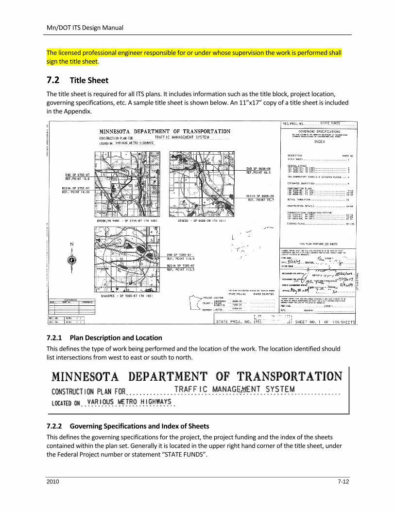
Mn/DOT ITS Design Manual
2010 7-12
The licensed professional engineer responsible for or under whose supervision the work is performed shall sign the title sheet.
7.2 Title Sheet
The title sheet is required for all ITS plans. It includes information such as the title block, project location, governing specifications, etc. A sample title sheet is shown below. An 11”x17” copy of a title sheet is included in the Appendix.
7.2.1 Plan Description and Location
This defines the type of work being performed and the location of the work. The location identified should list intersections from west to east or south to north.
7.2.2 Governing Specifications and Index of Sheets
This defines the governing specifications for the project, the project funding and the index of the sheets contained within the plan set. Generally it is located in the upper right hand corner of the title sheet, under the Federal Project number or statement “STATE FUNDS”.

Mn/DOT ITS Design Manual
2010 7-13
If designed in metric units, there must also be a statement to the left of this box: “Attention, this is a metric plan”.
7.2.3 Plan Preparation Certification Note
This identifies:
Who the plan set was developed by (or under the direct supervision of)
That individual’s state registration information.

Mn/DOT ITS Design Manual
2010 7-14
7.2.4 Project Numbers and Sheet Numbers
The project numbers and sheet numbers are shown in the lower right hand corner of the title sheet and on all other sheets. For revisions to the plan made after project advertisement, an “R” shall be used after the sheet number.
A SP in the project number stands for State Project. A SP is necessary for any project on a trunk highway signal. A SAP is a State Aid Project number indicating that the local agency is using State Aid funds to finance their share of the project. If the project has federal funding the SAP becomes a SP. All state aid numbers should be listed on all sheets to which they apply.
The general format for a SP is “CCNN‐A”. CC is the county number in alphabetical order (i.e., Anoka County is 02). NN is the control section number within the county unique to the roadway in the County. A is the number of the project on that control section (i.e., ‐269 means that there have been 268 other projects on this section of roadway prior to this project).
The general format for an SAP is CCC‐NNN‐A. CCC is a 3‐digit city number, a two digit number is a county number. NNN is a number related to the roadway and project type. A is the number of the project in that city or county of that type.
7.2.5 Signature Block
7.2.6 Index Map
The index map is used to identify the location of the project(s). Provide leader lines from the beginning and end of the project limits to the appropriate points on the map. This is generally located near the center of the title sheet.
If appropriate, identify all State Aid project numbers applicable to the project. Also, label all traffic signal systems.

Mn/DOT ITS Design Manual
2010 7-15
7.2.7 Project Location
The information included in this block is the generalized location (county and city). This is generally located in the lower right part of the title sheet, left of the signature block and above the project number block.

Mn/DOT ITS Design Manual
2010 7-16
7.2.8 Plan Revisions Block
The block is included so that future plan revisions can be documented. This is generally located in lower center portion of the title sheet. Pencil in the charge identifier number. Mn/DOT plan processing will edit this as necessary.
7.3 General Layout Sheets
The general layout sheets show the layout of the sheets within the project area.

Mn/DOT ITS Design Manual
2010 7-17
7.4 TMS Components Sheet

Mn/DOT ITS Design Manual
2010 7-18
7.4.1 Legend of Symbols
These are the standard symbols and abbreviations pertaining to the design.
7.4.2 Utility Notes
These are the general Utility Notes.
Utility Quality Level is a professional opinion about the quality and reliability of utility information. There are four levels of utility quality information, ranging from the most precise and reliable, level A, to the least precise and reliable, level D. The utility quality level must be determined in accordance with guidelines established by the Construction Institute of the American Society of Civil Engineers in document CI/ASCE 38‐02 entitled “Standard Guidelines for the Collection and Depiction of Existing Subsurface Utility Data.”
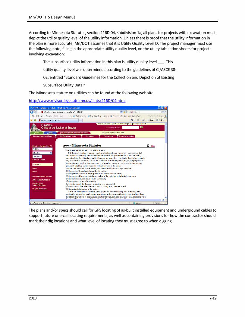
Mn/DOT ITS Design Manual
2010 7-19
According to Minnesota Statutes, section 216D.04, subdivision 1a, all plans for projects with excavation must depict the utility quality level of the utility information. Unless there is proof that the utility information in the plan is more accurate, Mn/DOT assumes that it is Utility Quality Level D. The project manager must use the following note, filling in the appropriate utility quality level, on the utility tabulation sheets for projects involving excavation:
The subsurface utility information in this plan is utility quality level ___. This
utility quality level was determined according to the guidelines of CI/ASCE 38‐
02, entitled “Standard Guidelines for the Collection and Depiction of Existing
Subsurface Utility Data.”
The Minnesota statute on utilities can be found at the following web site:
http://www.revisor.leg.state.mn.us/stats/216D/04.html
The plans and/or specs should call for GPS locating of as‐built installed equipment and underground cables to support future one‐call locating requirements, as well as containing provisions for how the contractor should mark their dig locations and what level of locating they must agree to when digging.

Mn/DOT ITS Design Manual
2010 7-20
7.4.3 List of Utility Ownership
This is list of the utility ownership in the project area. The table includes a note of how the utilities should be impacted (ie, LEAVE AS IS).
7.4.4 Standard Plates Summary
This identifies the list of Standard Plates that are applicable to this project.

Mn/DOT ITS Design Manual
2010 7-21
7.5 Quantities Sheet
This sheet shows the estimated quantities for the project. The Total Quantity and the quantity by project number shall be shown.
The appropriate specification item numbers, item descriptions, and units using the state’s computerized pay item list shall be included.
Refer to the TRNS*PORT Web Site (www.dot.state.mn.us/stateaid/res_trnsport_list.html) for a listing of the following:
Item Number & Extension,
Short Description,
Long Description,
Four Character Computer Code for the Unit Name, and
Desired Plan Sheet Unit Name
State Aid participation should be clearly identified for each item.
Don’t forget to include software maintenance fees in your cost estimates.
7.6 Construction Plans
The Construction Layout sheet(s) includes the following (at a minimum):
Roadway geometrics (to scale)

Mn/DOT ITS Design Manual
2010 7-22
All graphics depicting signal system components
Component Installation notes
Equipment pad notes (when applicable)
Source of power notes (when applicable)
Plan sheet title and revision block (on all sheets)
A bar scale
A north arrow
Highway and/or Street names
Metric logo (as necessary)
DO NOT show utilities on the layout sheet, include additional sheet(s) for utilities.

Mn/DOT ITS Design Manual
2010 7-23
7.7 Detail Tabulation
7.8 Detail Sheets
The detail sheets show the standard details that are applicable to the project. They may include the following details.

Mn/DOT ITS Design Manual
2010 7-24
7.8.1 Handhole Detail
7.8.2 Fiber Optic Pulling Vault

Mn/DOT ITS Design Manual
2010 7-25
7.8.3 Fiber Optic Splice Vault
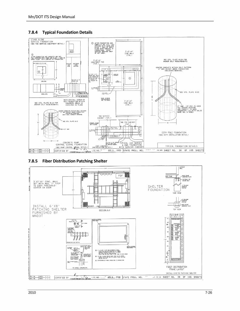
Mn/DOT ITS Design Manual
2010 7-26
7.8.4 Typical Foundation Details
7.8.5 Fiber Distribution Patching Shelter

Mn/DOT ITS Design Manual
2010 7-27
7.8.6 Typical Cabinet Installation
7.8.7 TMS Service Cabinet

Mn/DOT ITS Design Manual
2010 7-28
7.8.8 Typical DMS 334 Cabinet Installation
7.8.9 One‐way Ramp Control Signal Detail

Mn/DOT ITS Design Manual
2010 7-29
7.8.10 Ramp Control Signal Control Cable Termination Guide
7.8.11 Signing Layout Detail (Without HOV)

Mn/DOT ITS Design Manual
2010 7-30

Mn/DOT ITS Design Manual
2010 7-31

Mn/DOT ITS Design Manual
2010 7-32

Mn/DOT ITS Design Manual
2010 7-33

Mn/DOT ITS Design Manual
2010 7-34

Mn/DOT ITS Design Manual
2010 7-35

Mn/DOT ITS Design Manual
2010 7-36

Mn/DOT ITS Design Manual
2010 7-37
7.9 Wiring Diagrams
The field wiring diagram is used to describe how the actual field wiring shall be placed. Some of the issues associated with this sheet include:
7.10 Fiber Connection Charts

Mn/DOT ITS Design Manual
2010 7-38

Mn/DOT ITS Design Manual
2010 7-39

Mn/DOT ITS Design Manual
2010 7-40

Mn/DOT ITS Design Manual
2010 8-1
8. STANDARD AND SPECIAL PROVISIONS
In this chapter,
8.1 Mn/DOT Standard Specifications for Construction
http://www.dot.state.mn.us/pre‐letting/spec/index.html
The “Spec Book” contains standard specifications to be used and referred to in the design of traffic signal plans and in the preparing of traffic signal Special Provisions Plan designers need to be aware of the specifications contained in the Spec Book that may apply to their individual project.
The 2005 Spec Book includes both metric and non‐metric units of measure conversions. The 2005 Spec book also includes numerous modifications to the 2000 Spec Book Mn/DOT produces a new Spec Book on a 5 year cycle.
8.1.1 Format of the “Spec Book”
The Spec Book is made of three divisions:
Division I ‐ General Requirements and Covenants
Division II ‐ Construction Details
Division III ‐ Materials
A section of Division I that all designers need to be particularly aware of is as follows:
Mn/DOT 1504 ‐ “Coordination of Plans and Specifications”
“These Standard Specifications, the Plans, Special Provisions, supplemental Specifications, and all supplementary documents are essential parts of the Contract, and a requirement occurring in one is as binding as though occurring in all. They are intended to be complementary and to describe and provide for a complete work.
In case of discrepancy, calculated dimensions will govern over scaled dimensions; Special Provisions will govern over Standard and supplemental Specifications and Plans; Plans will govern over Standard and supplemental Specifications; supplemental Specifications will govern over Standard Specifications.
The Engineer will decide all issues concerning errors and omissions that are not otherwise resolved by logical conclusion or Contract modification. Both parties to the Contract shall inform each other as to any discrepancies they uncover, and neither the Contractor nor the Engineer shall take advantage of any error or omission.
In the interest of avoiding repetitious wording in the Specifications, certain words and phrases have been omitted where reference is clearly related by expressions of authority or intention. Where certain words and terms appear, they are to be construed with reference to the definitions, abbreviations, heading, titles, item names, and other pertinent provisions of the Contract documents, as may be implied.”
8.1.2 Format of Mn/DOT 2565 (Traffic Signals)
Division II contains Mn/DOT 2565 (Traffic Control Signals).
Mn/DOT ITS Design Manual
2010 8-2
The format of Mn/DOT 2565 is as follows:
Description:
Has a General information section.
Has a Definitions section. Materials:
Has a General information section.
Specifies various materials, including references to Division III of the Spec Book. Construction Requirements:
Has a General information section.
Specifies the requirements for actually constructing either a traffic control signal system or an electric lighting system. Mn/DOT 2545 (Electric lighting systems) does cross reference a number of specifications within Mn/DOT 2565.
Method of Measurement:
Traffic control signal systems are measured as an integral unit complete in place and operating with the complete installation at one intersection being considered one unit.
Basis of Payment:
There is a payment schedule listed in this section that shows the Item No., Item, and Unit. There is only one item used for traffic control signal systems in the Spec Book, however, signal system projects do use other “individual” pay items. These pay items are written as part of the Special Provisions. See the Special Provisions section of this Chapter for some examples of the pay items used for signal system projects.
Division III includes a section entitled “Electrical Materials” which contains various material specifications for signal systems. Many of these material specifications are referred to by Mn/DOT 2565. The format of these material specifications are divided into: Scope, Requirements, and Inspection and Testing.
Other National and Local Standards
There are other national and local standards which are applicable to signal plans and specifications. The following are some of the standards specified in the Spec Book:
AASHTO American Association of State Highway and Transportation Officials
ASTM American Society of Testing and Materials
ITE Institute of Transportation Engineers
ICEA Insulated Cable Engineers Association
NEC National Electrical Code
NEMA National Electrical Manufacturers Association
RUS Rural Utilities Service
UL Underwriter Laboratories, Inc.
8.1.3 Supplemental Specifications
Supplemental specifications are additions and revisions to the standard specifications that are approved after the standard specifications book has been printed and distributed. They are published separately

Mn/DOT ITS Design Manual
2010 8-3
(usually in paperback booklet form) until the next updated Spec Book is published and released. The Plan and Proposal for each specific project needs to state if there are supplemental specifications that apply.
8.2 Special Provisions
Special Provisions are defined as:
“Additions and revisions to the Standard and Supplemental Specifications covering conditions peculiar to an individual project”
Special Provisions are just that: “SPECIAL” provisions. If an item(s) is adequately addressed or specified in the Spec Book, Standard Plates, Plan, or other Contract documents, then that item(s) should not be duplicated within the Special Provisions.
Division SS covers signal systems. Special Provisions may be formatted into more than one SS section. For example:
Traffic Signal System (Division SS)
SS‐1 Qualifications of Workers
SS‐2 Traffic Control Signals
SS‐3 Emergency Vehicle Preemption (EVP) System
SS‐4 Traffic Control Interconnection
A typical set of Special Provisions for a signal system are formatted similar to the Spec Book; however, the actual format of the Special Provisions may vary somewhat when compared to the Spec Book format. The following is how the Special Provisions for signal systems are formatted:
Opening Descriptive Paragraph
General Section
Materials
Construction Requirements
Measurement and Payment Special Provisions may also include detail drawings that are pertinent to the specific project.
All signal system Special Provisions that are part of the Mn/DOT projects or have State Aid money involved will have a SS‐1 “Qualification of Workers” specification.
The following is a closer look at a typical set of Special Provisions for a signal system:
Qualification of Workers
This section requires Signal and Lighting Certification for all Contractors’ Supervisors and Foreman involved in the field installation of traffic signal and lighting system projects. This language is required in the Special Provisions for any project that involves Mn/DOT and State Aid projects.
Traffic Control Signals
Signal provisions will have a description paragraph of the work: what work is involved, location of project; and what documents the project shall be in accordance with.
General Section:
This section will usually include a list of Department furnished materials being supplied to the Contractor and language specifying where the Contractor is to pick‐up the Department furnished materials. This section may

Mn/DOT ITS Design Manual
2010 8-4
also include any Plan changes, notes to bidders, specifying whether or not an agreement will apply to the project, etc.
Materials Section:
This section will cover any material items that are not covered in other Contract documents, or language in other documents that needs to be modified for this specific project.
Construction Requirements:
This section contains language dealing with the actual construction of the signal system. Like the materials section, it will include language that modifies items in the Spec Book, Plan, or other Contract documents.
Measurement and Payment:
This section will specify exactly how the signal system will be measured and paid for. The pay item(s) in this section need to match the pay item(s) listed on the estimated quantity sheet in the Plan.
The following is a “sample” pay item for a signal system set of Special Provisions:
Removing and salvaging the existing traffic control signal system; furnishing and installing materials and electrical equipment; and installing Department furnished materials as specified herein, all to provide a complete operating new full‐traffic‐actuated traffic control signal system at the intersection of _____________ and _____________ in _________, ________ County as contained in these Special Provisions and in the Plans will be measured as an integral unit and paid for as specified in Mn/DOT 2565.4 and Mn/DOT 2565.5 respectively for Item No. 2565.511 (TRAFFIC CONTROL SIGNAL SYSTEM).
See the Appendix for a sample of a typical set of Mn/DOT Special Provisions and the typical specifications that are included in the various sections
8.3 Approved Products List
http://www.dot.state.mn.us/products/

Mn/DOT ITS Design Manual
2010 9-1
9. APPENDIX