MN750 Ver. 7/98 - Baldor.com
84
Baldor SmartMotor Installation & Operating Manual 7/98 MN750 ADJUSTABLE SPEED DRIVE
Transcript of MN750 Ver. 7/98 - Baldor.com

Baldor SmartMotor
Installation & Operating Manual
7/98 MN750
ADJUSTABLE SPEED DRIVE

Table of Contents
Table of Contents iMN750
Section 1Quick Start Guide 1-1. . . . . . . . . . . . . . . . . . . . . . . . . . . . . . . . . . . . . . . . . . . . . . . . . . . . . . . . . . . . . . . . . . . . . . . . . . . . . . . .
Overview 1-1. . . . . . . . . . . . . . . . . . . . . . . . . . . . . . . . . . . . . . . . . . . . . . . . . . . . . . . . . . . . . . . . . . . . . . . . . . . . . . . . . . . .
Section 2General Information 2-1. . . . . . . . . . . . . . . . . . . . . . . . . . . . . . . . . . . . . . . . . . . . . . . . . . . . . . . . . . . . . . . . . . . . . . . . . . . . . .
Overview 2-1. . . . . . . . . . . . . . . . . . . . . . . . . . . . . . . . . . . . . . . . . . . . . . . . . . . . . . . . . . . . . . . . . . . . . . . . . . . . . . . . . . . .
Safety Notice: 2-3. . . . . . . . . . . . . . . . . . . . . . . . . . . . . . . . . . . . . . . . . . . . . . . . . . . . . . . . . . . . . . . . . . . . . . . . . . . . . . . .
Precautions: 2-3. . . . . . . . . . . . . . . . . . . . . . . . . . . . . . . . . . . . . . . . . . . . . . . . . . . . . . . . . . . . . . . . . . . . . . . . . . . . .
Section 3Receiving & Installation 3-1. . . . . . . . . . . . . . . . . . . . . . . . . . . . . . . . . . . . . . . . . . . . . . . . . . . . . . . . . . . . . . . . . . . . . . . . . . .
Receiving & Inspection 3-1. . . . . . . . . . . . . . . . . . . . . . . . . . . . . . . . . . . . . . . . . . . . . . . . . . . . . . . . . . . . . . . . . . . . . . . . .
Overview 3-1. . . . . . . . . . . . . . . . . . . . . . . . . . . . . . . . . . . . . . . . . . . . . . . . . . . . . . . . . . . . . . . . . . . . . . . . . . . . . . . . . . . .
Location and Mounting 3-1. . . . . . . . . . . . . . . . . . . . . . . . . . . . . . . . . . . . . . . . . . . . . . . . . . . . . . . . . . . . . . . . . . . . .
AC Power Considerations 3-2. . . . . . . . . . . . . . . . . . . . . . . . . . . . . . . . . . . . . . . . . . . . . . . . . . . . . . . . . . . . . . . . . . . . . .
AC Line Impedance 3-2. . . . . . . . . . . . . . . . . . . . . . . . . . . . . . . . . . . . . . . . . . . . . . . . . . . . . . . . . . . . . . . . . . . . . . .
Protective Devices 3-3. . . . . . . . . . . . . . . . . . . . . . . . . . . . . . . . . . . . . . . . . . . . . . . . . . . . . . . . . . . . . . . . . . . . . . . .
Power Disconnect 3-3. . . . . . . . . . . . . . . . . . . . . . . . . . . . . . . . . . . . . . . . . . . . . . . . . . . . . . . . . . . . . . . . . . . . . . . . .
AC Power Connections 3-4. . . . . . . . . . . . . . . . . . . . . . . . . . . . . . . . . . . . . . . . . . . . . . . . . . . . . . . . . . . . . . . . . . . .
DC Power Connections 3-4. . . . . . . . . . . . . . . . . . . . . . . . . . . . . . . . . . . . . . . . . . . . . . . . . . . . . . . . . . . . . . . . . . . .
Installing Optional Items 3-6. . . . . . . . . . . . . . . . . . . . . . . . . . . . . . . . . . . . . . . . . . . . . . . . . . . . . . . . . . . . . . . . . . . . . . . .
Dynamic Braking (DB) Hardware 3-6. . . . . . . . . . . . . . . . . . . . . . . . . . . . . . . . . . . . . . . . . . . . . . . . . . . . . . . . . . . .
Optional Remote Keypad Mounting 3-6. . . . . . . . . . . . . . . . . . . . . . . . . . . . . . . . . . . . . . . . . . . . . . . . . . . . . . . . .
Analog Input and Output 3-7. . . . . . . . . . . . . . . . . . . . . . . . . . . . . . . . . . . . . . . . . . . . . . . . . . . . . . . . . . . . . . . . . . . . . . .
Analog Input 3-7. . . . . . . . . . . . . . . . . . . . . . . . . . . . . . . . . . . . . . . . . . . . . . . . . . . . . . . . . . . . . . . . . . . . . . . . . . . . .
Analog Output 3-8. . . . . . . . . . . . . . . . . . . . . . . . . . . . . . . . . . . . . . . . . . . . . . . . . . . . . . . . . . . . . . . . . . . . . . . . . . . .
External Trip Input 3-8. . . . . . . . . . . . . . . . . . . . . . . . . . . . . . . . . . . . . . . . . . . . . . . . . . . . . . . . . . . . . . . . . . . . . . . . . . . . .
Opto Isolated Inputs and Output 3-9. . . . . . . . . . . . . . . . . . . . . . . . . . . . . . . . . . . . . . . . . . . . . . . . . . . . . . . . . . . . . . . . .
Opto-isolated Inputs 3-9. . . . . . . . . . . . . . . . . . . . . . . . . . . . . . . . . . . . . . . . . . . . . . . . . . . . . . . . . . . . . . . . . . . . . . .
Opto-Isolated Output 3-10. . . . . . . . . . . . . . . . . . . . . . . . . . . . . . . . . . . . . . . . . . . . . . . . . . . . . . . . . . . . . . . . . . . . . .
Operating Mode & Connection Diagram Examples 3-11. . . . . . . . . . . . . . . . . . . . . . . . . . . . . . . . . . . . . . . . . . . . . . . . .
Keypad Operating Mode 3-11. . . . . . . . . . . . . . . . . . . . . . . . . . . . . . . . . . . . . . . . . . . . . . . . . . . . . . . . . . . . . . . . . . .
#1, 2 Wire 7 Speed Operating Mode 3-12. . . . . . . . . . . . . . . . . . . . . . . . . . . . . . . . . . . . . . . . . . . . . . . . . . . . . . . . .
#2, 2 Wire External Trip Operating Mode 3-13. . . . . . . . . . . . . . . . . . . . . . . . . . . . . . . . . . . . . . . . . . . . . . . . . . . . .
#3, 2 Wire 3 Speed Operating Mode 3-14. . . . . . . . . . . . . . . . . . . . . . . . . . . . . . . . . . . . . . . . . . . . . . . . . . . . . . . . .
#4, 3 Wire 3 Speed Operating Mode 3-15. . . . . . . . . . . . . . . . . . . . . . . . . . . . . . . . . . . . . . . . . . . . . . . . . . . . . . . . .
#5, 3 Wire External Trip Operating Mode 3-16. . . . . . . . . . . . . . . . . . . . . . . . . . . . . . . . . . . . . . . . . . . . . . . . . . . . .
#6, 2 Wire Electronic Pot Operating Mode 3-17. . . . . . . . . . . . . . . . . . . . . . . . . . . . . . . . . . . . . . . . . . . . . . . . . . . .
#7, 3 Wire, Electronic Pot Operating Mode 3-18. . . . . . . . . . . . . . . . . . . . . . . . . . . . . . . . . . . . . . . . . . . . . . . . . . . .
Profile Run Remote Operating Mode 3-19. . . . . . . . . . . . . . . . . . . . . . . . . . . . . . . . . . . . . . . . . . . . . . . . . . . . . . . . .
Profile Run Local Operating Mode 3-20. . . . . . . . . . . . . . . . . . . . . . . . . . . . . . . . . . . . . . . . . . . . . . . . . . . . . . . . . . .
Pre-Operation Checklist 3-21. . . . . . . . . . . . . . . . . . . . . . . . . . . . . . . . . . . . . . . . . . . . . . . . . . . . . . . . . . . . . . . . . . . . . . . .

ii Table of Contents MN750
Section 4Programming & Operation 4-1. . . . . . . . . . . . . . . . . . . . . . . . . . . . . . . . . . . . . . . . . . . . . . . . . . . . . . . . . . . . . . . . . . . . . . . .
Overview 4-1. . . . . . . . . . . . . . . . . . . . . . . . . . . . . . . . . . . . . . . . . . . . . . . . . . . . . . . . . . . . . . . . . . . . . . . . . . . . . . . . . . . .
Display Mode 4-2. . . . . . . . . . . . . . . . . . . . . . . . . . . . . . . . . . . . . . . . . . . . . . . . . . . . . . . . . . . . . . . . . . . . . . . . . . . . . . . . .
Adjusting Display Contrast 4-2. . . . . . . . . . . . . . . . . . . . . . . . . . . . . . . . . . . . . . . . . . . . . . . . . . . . . . . . . . . . . . . . .
Display Screens 4-3. . . . . . . . . . . . . . . . . . . . . . . . . . . . . . . . . . . . . . . . . . . . . . . . . . . . . . . . . . . . . . . . . . . . . . . . . .
Diagnostic Screens 4-4. . . . . . . . . . . . . . . . . . . . . . . . . . . . . . . . . . . . . . . . . . . . . . . . . . . . . . . . . . . . . . . . . . . . . . .
Fault Log Access 4-5. . . . . . . . . . . . . . . . . . . . . . . . . . . . . . . . . . . . . . . . . . . . . . . . . . . . . . . . . . . . . . . . . . . . . . . . .
Program Mode 4-5. . . . . . . . . . . . . . . . . . . . . . . . . . . . . . . . . . . . . . . . . . . . . . . . . . . . . . . . . . . . . . . . . . . . . . . . . . . . . . . .
Parameter Blocks Access for Programming 4-6. . . . . . . . . . . . . . . . . . . . . . . . . . . . . . . . . . . . . . . . . . . . . . . . . . .
Changing Parameter Values when Security Code Not Used 4-7. . . . . . . . . . . . . . . . . . . . . . . . . . . . . . . . . . . . .
Reset Parameters to Factory Settings 4-8. . . . . . . . . . . . . . . . . . . . . . . . . . . . . . . . . . . . . . . . . . . . . . . . . . . . . . .
Operating the SmartMotor from the Keypad 4-9. . . . . . . . . . . . . . . . . . . . . . . . . . . . . . . . . . . . . . . . . . . . . . . . . . .
Using the Keypad JOG Command 4-9. . . . . . . . . . . . . . . . . . . . . . . . . . . . . . . . . . . . . . . . . . . . . . . . . . . . . . . . . . .
Speed Adjustment from the Keypad 4-10. . . . . . . . . . . . . . . . . . . . . . . . . . . . . . . . . . . . . . . . . . . . . . . . . . . . . . . . .
Speed Adjustment Using Arrow Keys 4-10. . . . . . . . . . . . . . . . . . . . . . . . . . . . . . . . . . . . . . . . . . . . . . . . . . . . . . . .
Profile Run Changes 4-11. . . . . . . . . . . . . . . . . . . . . . . . . . . . . . . . . . . . . . . . . . . . . . . . . . . . . . . . . . . . . . . . . . . . . .
Security System Changes 4-12. . . . . . . . . . . . . . . . . . . . . . . . . . . . . . . . . . . . . . . . . . . . . . . . . . . . . . . . . . . . . . . . . .
Changing Parameter Values with a Security Code in Use 4-13. . . . . . . . . . . . . . . . . . . . . . . . . . . . . . . . . . . . . . .
Security System Access Timeout Parameter Change 4-14. . . . . . . . . . . . . . . . . . . . . . . . . . . . . . . . . . . . . . . . . .
SmartMotor Parameters 4-15. . . . . . . . . . . . . . . . . . . . . . . . . . . . . . . . . . . . . . . . . . . . . . . . . . . . . . . . . . . . . . . . . . . . . . . .
Parameter Description 4-16. . . . . . . . . . . . . . . . . . . . . . . . . . . . . . . . . . . . . . . . . . . . . . . . . . . . . . . . . . . . . . . . . . . . . . . . .
Section 5Troubleshooting 5-1. . . . . . . . . . . . . . . . . . . . . . . . . . . . . . . . . . . . . . . . . . . . . . . . . . . . . . . . . . . . . . . . . . . . . . . . . . . . . . . . .
Overview 5-1. . . . . . . . . . . . . . . . . . . . . . . . . . . . . . . . . . . . . . . . . . . . . . . . . . . . . . . . . . . . . . . . . . . . . . . . . . . . . . . . . . . .
Troubleshooting 5-1. . . . . . . . . . . . . . . . . . . . . . . . . . . . . . . . . . . . . . . . . . . . . . . . . . . . . . . . . . . . . . . . . . . . . . . . . . . . . . .
How to Access Display Screens and Diagnostic Information 5-2. . . . . . . . . . . . . . . . . . . . . . . . . . . . . . . . . . . . . . . . .
No Keypad Display 5-7. . . . . . . . . . . . . . . . . . . . . . . . . . . . . . . . . . . . . . . . . . . . . . . . . . . . . . . . . . . . . . . . . . . . . . . .
Diagnostic Information Screens 5-3. . . . . . . . . . . . . . . . . . . . . . . . . . . . . . . . . . . . . . . . . . . . . . . . . . . . . . . . . . . . .
How to Set Date and Time 5-4. . . . . . . . . . . . . . . . . . . . . . . . . . . . . . . . . . . . . . . . . . . . . . . . . . . . . . . . . . . . . . . . .
How to Access the Fault Log 5-5. . . . . . . . . . . . . . . . . . . . . . . . . . . . . . . . . . . . . . . . . . . . . . . . . . . . . . . . . . . . . . .
How to Clear the Fault Log 5-5. . . . . . . . . . . . . . . . . . . . . . . . . . . . . . . . . . . . . . . . . . . . . . . . . . . . . . . . . . . . . . . . .
Restore Factory Parameter Values 5-8. . . . . . . . . . . . . . . . . . . . . . . . . . . . . . . . . . . . . . . . . . . . . . . . . . . . . . . . . .

Table of Contents iiiMN750
Section 6Specifications & Product Data 6-1. . . . . . . . . . . . . . . . . . . . . . . . . . . . . . . . . . . . . . . . . . . . . . . . . . . . . . . . . . . . . . . . . . . . .
Specifications: 6-1. . . . . . . . . . . . . . . . . . . . . . . . . . . . . . . . . . . . . . . . . . . . . . . . . . . . . . . . . . . . . . . . . . . . . . . . . . . . . . . .
Ratings 6-5. . . . . . . . . . . . . . . . . . . . . . . . . . . . . . . . . . . . . . . . . . . . . . . . . . . . . . . . . . . . . . . . . . . . . . . . . . . . . . . . . . . . . .
Terminal Tightening Torque Specifications 6-6. . . . . . . . . . . . . . . . . . . . . . . . . . . . . . . . . . . . . . . . . . . . . . . . . . . . . . . .
Baldor SmartMotor 35 Frame 6-7. . . . . . . . . . . . . . . . . . . . . . . . . . . . . . . . . . . . . . . . . . . . . . . . . . . . . . . . . . . . . . . . .
Baldor SmartMotor 36 Frame 6-8. . . . . . . . . . . . . . . . . . . . . . . . . . . . . . . . . . . . . . . . . . . . . . . . . . . . . . . . . . . . . . . . .
Baldor SmartMotor 37 Frame 6-9. . . . . . . . . . . . . . . . . . . . . . . . . . . . . . . . . . . . . . . . . . . . . . . . . . . . . . . . . . . . . . . . .
Appendix A A-1. . . . . . . . . . . . . . . . . . . . . . . . . . . . . . . . . . . . . . . . . . . . . . . . . . . . . . . . . . . . . . . . . . . . . . . . . . . . . . . . . . . . . .
Parameter Values A-1. . . . . . . . . . . . . . . . . . . . . . . . . . . . . . . . . . . . . . . . . . . . . . . . . . . . . . . . . . . . . . . . . . . . . . . . . . . . .
Appendix B B-1. . . . . . . . . . . . . . . . . . . . . . . . . . . . . . . . . . . . . . . . . . . . . . . . . . . . . . . . . . . . . . . . . . . . . . . . . . . . . . . . . . . . . .
Remote Keypad Mounting Template B-2. . . . . . . . . . . . . . . . . . . . . . . . . . . . . . . . . . . . . . . . . . . . . . . . . . . . . . . . . . . . .

iv Table of Contents MN750

Section 1Quick Start Guide
Quick Start Guide 1-1MN750
Overview If you are an experienced user of Baldor controls, you are probably already familiar withthe keypad programming and keypad operation methods. If so, this quick start guide hasbeen prepared for you. This procedure will help get your system up and running in thekeypad mode quickly and will allow motor and control operation to be verified. Thisprocedure assumes that the Control, Motor and Dynamic Brake hardware are correctlyinstalled (see Section 3 for procedures) and that you have an understanding of thekeypad programming & operation procedures. It is not necessary to wire the terminalstrip to operate in the Keypad mode (Section 3 describes terminal strip wiringprocedures). The quick start procedure is as follows:
1. Read the Safety Notice and Precautions in section 2 of this manual.
2. Mount the drive.
3. Connect AC power. Refer to Section 3 “AC Power Connections”.
4. Plug in the keypad. Refer to Section 3, “Optional Remote Keypad Mounting”procedure.
Check of Electrical Items
CAUTION: After completing the installation but before you apply power , besure to check the following items.
1. Verify AC line voltage at source matches the SmartMotor rating.
2. Inspect all power connections for accuracy, workmanship, tightness andcompliance to codes.
3. Verify SmartMotor is grounded to earth ground.
4. Check all signal wiring for accuracy.
5. Be certain all brake coils, contactors and relay coils have noise suppression.This should be an R-C filter for AC coils and reverse polarity diodes for DCcoils. MOV type transient suppression is not adequate.
WARNING: Make sure that unexpected operation of the motor shaft during startup will not cause injury to personnel or damage to equipment.
Check of Motor and Coupling
1. Verify freedom of motion of the motor shaft.
2. Verify that motor couplings are tight without backlash.
3. Verify the holding brakes, if any, are properly adjusted to fully release and set tothe desired torque value.
Temporary Application of Power
1. Check all electrical and mechanical connections before applying power to theSmartMotor.
2. Verify that control logic inputs at the J1 connector are proper.
3. Temporarily apply power and observe that the bus power indicator is on or thatthe optional keypad display is on (if Keypad is connected). If this indicationdoes not occur, check all connections and verify input voltage. If fault indicationoccurs, refer to the troubleshooting section of this manual.
4. Disconnect all power from the SmartMotor.

1-2 Quick Start Guide MN750
Minimum Required Parameter Settings and Control Set-up Checklist
If you are familiar with programming Baldor controls continue with the following steps. Ifnot, proceed to the programming section of this manual before applying power to thedrive.
Note: This list is the minimum program parameters required for operation of thecontrol for initial start-up.
1. Be sure drive operation is terminated and secured.
2. Remove all power sources from the motor. Wait at least 5 minutes beforeproceeding to step 3.
3. Remove cover. Remove the four (4) screws that secure the control cover andremove cover.
4. Connect the optional Keypad to the Keypad Connector (Figure 3-1). Run thekeypad wires through the conduit to motor case.
5. Install the control cover. Place the cover on the control and install & tighten thefour (4) screws that secure the control cover.
6. Apply power to the SmartMotor.
7. Set the operating mode at the Level 1 Input block Operating Mode parameter.
8. Set the desired minimum output frequency by setting the Min Output Freqparameter in the Level 2 Output Limits block.
9. Set the desired maximum output frequency by setting the Max Output Freqparameter in the Level 2 Output Limits block.
10. If the desired peak current limit is different than presently set the PK CurrentLimit parameter in the Level 2 Output Limits block.
11. If using an external analog command, check ANA CMD Select parameter toverify the SmartMotor is ready to accept your analog command signal.
12. Set the desired Volts/Hertz ratio by setting the V/HZ Profile Parameter in theLevel 2 V/HZ and Boost Block.
13. If the load is a high initial starting torque type, the Torque Boost parameter inthe Level 1 V/HZ and Boost Block may need to be increased. Also, the ACCELTIME #1 parameter in the Level 1 ACCEL/DECEL Rate block may need to beincreased.
14. Set the date and time parameter in the Diagnostic Info screens.
15. Select and program additional parameters to suit your application.

Section 2General Information
General Information 2-1MN750
Overview The Baldor SmartMotor is an integrated industrial motor and inverter control that issimple and fast to install. Using Baldor SmartMotor will give you:
Designed Motor and Control Compatibility - By integrating the control electronics andthe motor during the design and manufacturing process, we achieve better performanceand compatibility. Just size the drive to the load characteristics. We even make sizing tothe load characteristics easy by providing a Matched Performance curve.
Fewer Wiring Mistakes - Let Baldor pre-wire the motor to the control and eliminate onemajor wiring mistake potential. Just connect power and control wiring (if necessary) andyou’re ready to run. In addition, you save the cost of the wire and conduit between themotor and control. That is just another way Baldor adds value to our products. Baldorsaves you money and eliminates expensive errors.
Fewer Programming Errors - How many hours have been spent trying to program themotor control to the motor characteristics? The Baldor SmartMotor is a factoryassembled motor drive. Baldor pre-programs all the required motor setup adjustments.If you prefer, you can still access all the normal inverter adjustments through the optionalkeypad or standard RS-485 port to custom tailor your particular application.
Eliminate Reflected W ave Voltage - You may know this phenomenon by other namessuch as standing wave or voltage ring-up. If the distance between the motor and controlis long and the switching frequency is just right, a standing wave can form between themotor and control. These standing waves can increase the voltage at the motor terminalscausing the motor to fail prematurely. Locating the control near the motor can keep thisproblem from occurring. Until now it was not always possible to prevent long motor tocontrol distances. The distance between the Baldor SmartMotor control and motor ismeasured in inches not feet.
Eliminate Panel Space - Trying to retrofit an existing fixed speed application toincorporate variable speed control and don’t have the panel space to mount a motorcontrol? Not a problem with the Baldor SmartMotor . Since the control electronics areintegrated into the motor design you only need to supply a power disconnect. In manycases you can probably use the existing wiring and conduit running to the motor location.
Power Module - The Baldor SmartMotor uses a definite purpose integrated powermodule specifically designed for Baldor SmartMotor use. Environmental heating is themost damaging element for motor and control design. By using a definite purpose powermodule Baldor reduces the potential for damaging heat generated from the motor orcontrol. Simply taking a micro inverter and mounting it to a motor will not allow for costeffective integration. Premature failure has not been eliminated because the motorcontrol electronics were not designed for high ambient temperature operations.
Patented TEFC Control Electronics Cooling - By using the motor shaft mountedcooling fan we can offer smaller package sizes and cost effective cooling for the motorand control. This patented design has been refined over several generations of productsand the result can be seen on the Baldor SmartMotor .
High Efficiency Inverter Duty Motor Designs - Building on Baldor’s many years ofexperience in designing and manufacturing inverter duty motors, the BaldorSmartMotor incorporates the same design features as offered in our industry standardinverter duty motor product line. Some of the many features include Class H insulationsystem, 200oC Inverter Spike Resistant (ISR) magnet wire, low loss motor lamination,and precision rotor balance.
DC Bus Powered Logic Supply - The control circuitry is powered from the control’sinternal DC Bus for greater noise immunity and increased reliability. Additionally thepower-loss-ride-through capability is increased when compared to designs using ACpowered logic. The Baldor SmartMotor can be operated directly from a DC sourcesuch as found in automotive air conditioners and other battery powered devices.

2-2 General Information MN750
Limited Warranty
For a period of two (2) years from the date of original purchase, BALDOR willrepair or replace without charge controls which our examination proves tobe defective in material or workmanship. This warranty is valid if the unit hasnot been tampered with by unauthorized persons, misused, abused, orimproperly installed and has been used in accordance with the instructionsand/or ratings supplied. This warranty is in lieu of any other warranty orguarantee expressed or implied. BALDOR shall not be held responsible forany expense (including installation and removal), inconvenience, orconsequential damage, including injury to any person or property caused byitems of our manufacture or sale. (Some states do not allow exclusion orlimitation of incidental or consequential damages, so the above exclusionmay not apply.) In any event, BALDOR’s total liability, under allcircumstances, shall not exceed the full purchase price of the control.Claims for purchase price refunds, repairs, or replacements must bereferred to BALDOR with all pertinent data as to the defect, the datepurchased, the task performed by the control, and the problemencountered. No liability is assumed for expendable items such as fuses.
Goods may be returned only with written notification including a BALDORReturn Authorization Number and any return shipments must be prepaid.
General Information 2-3MN750
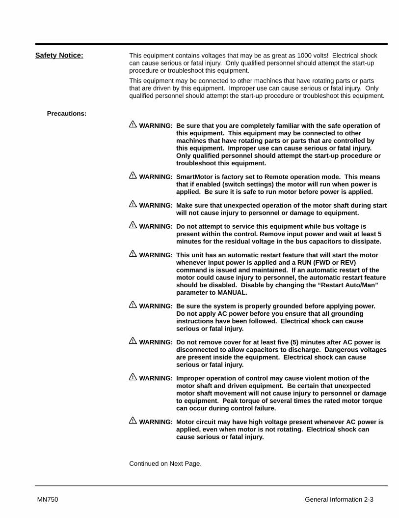
Safety Notice: This equipment contains voltages that may be as great as 1000 volts! Electrical shockcan cause serious or fatal injury. Only qualified personnel should attempt the start-upprocedure or troubleshoot this equipment.
This equipment may be connected to other machines that have rotating parts or partsthat are driven by this equipment. Improper use can cause serious or fatal injury. Onlyqualified personnel should attempt the start-up procedure or troubleshoot this equipment.
Precautions:
WARNING: Be sure that you are completely familiar with the safe operation ofthis equipment. This equipment may be connected to othermachines that have rotating parts or parts that are controlled bythis equipment. Improper use can cause serious or fatal injury .Only qualified personnel should attempt the start-up procedure ortroubleshoot this equipment.
WARNING: SmartMotor is factory set to Remote operation mode. This meansthat if enabled (switch settings) the motor will run when power isapplied. Be sure it is safe to run motor before power is applied.
WARNING: Make sure that unexpected operation of the motor shaft during startwill not cause injury to personnel or damage to equipment.
WARNING: Do not attempt to service this equipment while bus voltage ispresent within the control. Remove input power and wait at least 5minutes for the residual voltage in the bus capacitors to dissipate.
WARNING: This unit has an automatic restart feature that will start the motorwhenever input power is applied and a RUN (FWD or REV)command is issued and maintained. If an automatic restart of themotor could cause injury to personnel, the automatic restart featureshould be disabled. Disable by changing the “Restart Auto/Man”parameter to MANUAL.
WARNING: Be sure the system is properly grounded before applying power .Do not apply AC power before you ensure that all groundinginstructions have been followed. Electrical shock can causeserious or fatal injury .
WARNING: Do not remove cover for at least five (5) minutes after AC power isdisconnected to allow capacitors to discharge. Dangerous voltagesare present inside the equipment. Electrical shock can causeserious or fatal injury .
WARNING: Improper operation of control may cause violent motion of themotor shaft and driven equipment. Be certain that unexpectedmotor shaft movement will not cause injury to personnel or damageto equipment. Peak torque of several times the rated motor torquecan occur during control failure.
WARNING: Motor circuit may have high voltage present whenever AC power isapplied, even when motor is not rotating. Electrical shock cancause serious or fatal injury .
Continued on Next Page.

2-4 General Information MN750
Caution: T o prevent equipment damage, be certain that the electrical serviceis not capable of delivering more than 5000 RMS symmetricalamperes at rated voltage.
Caution: Do not mount the SmartMotor with the control cover in the downposition. The cover must face up or to one side to keep liquids andcontaminants away from the heatsink.
Caution: A void locating the SmartMotor immediately above or beside heatgenerating equipment, or directly below water or steam pipes.
Caution: Do not use power factor correction capacitors on the input powerlines to the SmartMotor. Damage to the control may result if theyare used.
Caution: Increasing the T orque Boost value may cause the motor to overheatat low speed.

Section 4Programming & Operation
Programming & Operation 4-1MN750
Overview The Baldor SmartMotor programming and operation is done with simple keystrokes onthe keypad. The keypad is used to program the control parameters and to operate themotor when programmed for the Keypad operating mode. The Keypad Display is used tomonitor the status and outputs of the control.
Figure 4-1 Keypad
JOG
JOG LOCAL PROG
FWD DISP
REV SHIFT ENTER
STOP RESET
Keypad Display - Displays statusinformation during Local or Remoteoperation. It also displays informationduring parameter setup and examinationof the Fault Log.JOG - Press JOG to select the
preprogrammed jog speed. After the jogkey has been pressed, use the FWD orREV keys to run the motor in thedirection that is needed. The JOG key isonly active in the local mode.
FWD - Press FWD to initiate forwardrotation of the motor. This key is onlyactive in the local mode.
REV - Press REV to initiate reverserotation of the motor. This key is activeonly in the local mode.
STOP - Press STOP to initiate a stopsequence. Depending on the setup of thecontrol, the motor will either ramp orcoast to a stop. This key is operationalin all modes of operation unless it hasbeen disabled by the Keypad Stopparameter in the Keypad (programming)Setup Block.
Note: If the control is operating in aremote mode and the stop keyis pressed the control willchange to the local mode whenthe stop command is initiated.to resume operation in theremote mode, press the LOCALkey.
LOCAL - Press LOCAL to change fromremote to local (keypad) or local toremote operation. When the control is inthe local mode all other externalcommands to the J1 terminal strip will beignored with the exception of theexternal trip input.
DISP - Press DISP to return to displaymode from programming mode. Providesoperational status and advances to thenext menu item. When in the programmode the DISP key is used to return tothe display mode.
SHIFT - Press SHIFT in the programmode to control cursor movement.Pressing the SHIFT key once moves theblinking cursor one character position tothe right. While in program mode, aparameter value may be rest to thefactory preset value by pressing theSHIFT key until the arrow symbols at thefar left of the keypad display are flashing,then press an arrow key. In the displaymode the SHIFT key is used to adjustthe keypad contrast.
RESET - Press RESET to clear all faultmessages (in local or remote modes).Can also be used to return to the top ofthe block programming menu withoutsaving any parameter value changes.
PROG - Press PROG to enter theprogram mode. While in the programmode the ENTER key is used to edit aparameter setting.
� - (UP Arrow). Press � to change the value of theparameter being displayed. Pressing �increments the value to the next greatervalue. Also, when the fault log orparameter list is displayed, the � key willscroll upward through the list. In thelocal mode pressing the � key willincrease motor speed to the next greatervalue.
� - (Down Arrow)Press � to change the value of theparameter being displayed. Pressing �decrements the value to the next lesservalue. Also, when the fault log orparameter list is displayed, the � key willscroll downward through the list. In thelocal mode pressing the � key willdecrease motor speed to the next lesservalue.
ENTER - Press ENTER to saveparameter value changes and moveback to the previous level in theprogramming menu. In the display modethe ENTER key is used to directly set thelocal speed reference. It is also used toselect other operations when promptedby the keypad display.
JOG - (Green) lights when Jog is active.FWD - (Green) lights when FWD direction is commanded.REV - (Green) lights when REV direction is commanded.STOP - (Red) lights when motor STOP is commanded.Indicator Lights
�

4-2 Programming & Operation MN750
Display Mode During normal operation the controller is in the DISPLAY MODE and the keypad displaysthe status of the control. When AC power is applied to the control, the keypad shoulddisplay the status of the control. There are several output status values that can bemonitored. When the control is in the DISPLAY MODE the information appears asfollows:
Motor Status* Control Operation
Output ConditionValue and Units
* If the Level 1 Input block, Operating Mode parameter is set to “Profile Run” , the display will change as follows:
Local Mode = LOCA or LCARemote Mode = REMA or RMA
In this example, the Control Operation would display “LOCA”.
In addition, the DISPLAY MODE offers a combined display that gives the value of alloutput conditions simultaneously. The DISPLAY MODE also gives the user the ability toview diagnostic information and the FAULT LOG.
If there is no display visible, check to make sure that the brightness and contrast settingsfor the keypad display are correctly set. Use the following procedure to adjust thebrightness and contrast of the display:
Adjusting Display Contrast (Contrast may be adjusted in display mode when motor is stopped or is running)
Action Description Display Comments
Apply Power No visible display
Press DISP Key Places control in display mode
Press SHIFT Allows display contrastadjustment
Press � or � Key Adjusts display intensity
Press ENTER Saves level of contrast and exitsto display mode
Typical display

Programming & Operation 4-3MN750
Display Screens
Action Description Display Comments
Apply Power Logo display for 5 seconds.
Display mode showing outputfrequency (Local Mode) �
No faults present. Local keypadmode. If in remote/serial mode,press local for this display.
Press DISP key Display mode showing motorspeed (based on outputfrequency).
Press DISP key Display mode showing outputcurrent.
Press DISP key Display mode showing outputvoltage.
Press DISP key Display mode showing outputvoltage, current, frequency andmotor RPM.
Press DISP key Fault Log entry point. To skip anddisplay next screen, press DISP.
Press ENTER to access the faultlog.
Press DISP key Diagnostic information entry point.Press DISP to continue to nextdisplay screen.
Press ENTER to accessdiagnostic information.
Press DISP key Modified parameter list entrypoint. To skip and display nextscreen, press DISP.
Press ENTER to access the list ofparameters modified from thefactory set values.
Press DISP key Speed command entry point. Toskip and display next screen,press DISP.
Press ENTER to access thespeed command entry point.
���In Auto mode, the display would be as follows:
Action Description Display Comments
Display mode showing outputfrequency (Profile Run) Level 1 Input block, OperatingMode set to “PROF RUN-LOC”
No faults present. Local keypadmode. If in remote/serial mode,press local for this display.
Stop mode (FWD or REV)LOCA (Local-Auto), REMA (Remote-Auto), means the
operating mode is set to PROFRUN-LOC or PROF RUN-REM.
Profile cycles remaining.Present running output frequency.
Seconds remaining in the present speed of the profile
Number of the preset speed that is presently running(Level 2 Profile Run block, SPD#Curve/DIR)

4-4 Programming & Operation MN750
Diagnostic Screens
Action Description Display Comments
Apply Power Logo display for 5 seconds.
Display mode showing outputfrequency (Local Mode) �
No faults present. Local keypadmode. If in remote/serial mode,press local for this display.
Press DISP key 6 times Scroll to diagnostic info block. Press ENTER to view diagnosticinformation if desired.
Press ENTER key Access diagnostic information.
Press DISP key Display mode showing controltemperature. 25.0
Displays operating temperature indegrees C.
Press DISP key Display mode showing busvoltage.
Press DISP key Display mode showing PWMFrequency. 2497
Press DISP key Display mode showing %overload current remaining.
Press DISP key Display mode showing real timeopto inputs & outputs states.(0=Open, 1=Closed)
Opto Inputs states (Left); Opto Outputs states (Right).
Press DISP key Display mode showing presentdate and time.
HR.MIN.SEC format.
Press DISP key Display operating zone with ratedHP and input voltage (for theoperating zone) and control type.
Press DISP key Display mode showing expansionboard installed.
Press DISP key Display mode showing softwareversion and revision installed inthe control.
Press DISP key Examine memory contents.Intended for service use only.
Press DISP key Displays exit choice. Press ENTER to exit.
Press ENTER to exit diagnosticinformation.

Programming & Operation 4-5MN750
Fault Log Access
When a fault condition occurs, motor operation stops and a fault code is displayed on theKeypad display. The control keeps a log of up to the last 31 faults. If more than 31 faultshave occurred the oldest fault will be deleted from the fault log to make room for thenewest fault. To access the fault log perform the following procedure:
Action Description Display Comments
Apply Power Logo display for 5 seconds.
Display mode showing outputfrequency
Display mode.
Press DISP key Press DISP to scroll to the FaultLog entry point.
Press ENTER key Diagnostic information entry point.To skip and display next screen,press DISP.
Typical display of fault, date andtime of fault.
Press � or � key Scroll through fault messages. If no messages, the fault log exitchoice is displayed.
Press ENTER key Return to display mode. Display mode stop key LED is on.
Program Mode Use the Program Mode to customize the control for a variety of applications byprogramming the operating parameters. From the Display Mode press the PROG key toaccess the Program Mode. To return to the Display Mode, press the DISP key. Note thatonce a parameter is selected alternately pressing the Disp and Prog keys will changebetween the Display Mode and the selected parameter. When a parameter is selectedfor programming, the keypad display provides the following information:
ParameterStatus
Parameter DescriptionValue and Units
Parameter StatusP: All programmable parameters are displayed with a P: in the lower left hand corner of
the keypad display.V: If a parameter is displayed with a V:, the setting may be viewed but not changed while
the motor is operating (or may only be changed by the factory, e.g. Motor Data).L: If the parameter is displayed with an L:, the setting is locked and the security access
code must be entered before any changes can be made.

4-6 Programming & Operation MN750
Parameter Blocks Access for Programming Use the following procedure to access parameter blocks to programthe SmartMotor.
Action Description Display Comments
Apply Power Keypad Display shows thisopening message.
Logo display for 5 seconds.
If no faults and programmed forLOCAL operation.
Display mode.
If no faults and programmed forREMOTE operation.
Display mode.
If fault is displayed, refer to theTroubleshooting section of thismanual.
Press PROG key Press ENTER to access presetspeed parameters.
Press � or � key Scroll to the ACCEL/DECELblock.
Press ENTER to access Acceland Decel rate parameters.
Press � or � key Scroll to the Level 2 Block. Press ENTER to access Level 2Blocks.
Press ENTER key Level 2 block entry point. Scroll to desired parameter value.Make changes as desired.
Press � or � key Scroll to Programming Exit menu.
Press ENTER key Return to display mode.
Programming & Operation 4-7MN750
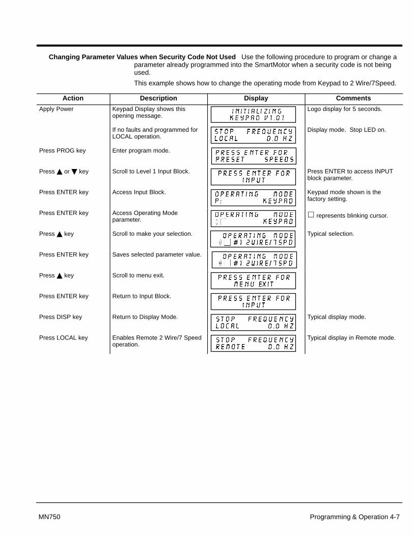
Changing Parameter V alues when Security Code Not Used Use the following procedure to program or change aparameter already programmed into the SmartMotor when a security code is not beingused.
This example shows how to change the operating mode from Keypad to 2 Wire/7Speed.
Action Description Display Comments
Apply Power Keypad Display shows thisopening message.
Logo display for 5 seconds.
If no faults and programmed forLOCAL operation.
Display mode. Stop LED on.
Press PROG key Enter program mode.
Press � or � key Scroll to Level 1 Input Block. Press ENTER to access INPUTblock parameter.
Press ENTER key Access Input Block. Keypad mode shown is thefactory setting.
Press ENTER key Access Operating Modeparameter.
� represents blinking cursor.
Press � key Scroll to make your selection. Typical selection.
Press ENTER key Saves selected parameter value.
Press � key Scroll to menu exit.
Press ENTER key Return to Input Block.
Press DISP key Return to Display Mode. Typical display mode.
Press LOCAL key Enables Remote 2 Wire/7 Speedoperation.
Typical display in Remote mode.

4-8 Programming & Operation MN750
Reset Parameters to Factory Settings Sometimes it is necessary to restore the parameter values to the factorysettings. Follow this procedure to do so. Note that any of your specific applicationparameters will be lost when resetting the control to factory settings.
Action Description Display Comments
Apply Power Keypad Display shows thisopening message.
Logo display for 5 seconds.
If no faults and programmed forLOCAL operation.
Display mode. Stop LED on.
Press PROG key Enter program mode.
Press � or � key Scroll to Level 2 Blocks.
Press ENTER key Select Level 2 Blocks.
Press � key Scroll to the Miscellaneous block.
Press ENTER key Select Miscellaneous block.
Press � key Scroll to Factory Settingsparameter.
Press ENTER key Access Factory Settingsparameter.
� represents blinking cursor.
Press � key Scroll to YES, to choose originalfactory settings.
Press ENTER key Restores factory settings.
*
“*Loading Presets” is firstmessage“Operation Done” is next.
Press � key Scroll to menu exit.
Press DISP key Return to display mode. Display mode. Stop LED on.

Programming & Operation 4-9MN750
Operating the SmartMotor from the Keypad If the control is configured for remote or serial control, the LOCALMode must be activated before the controller may be operated from the keypad. Toactivate the LOCAL Mode the motor must, first be stopped using the keypad STOP key (ifenabled), or by remote commands or serial commands.
Note: Pressing the keypad STOP key (if enabled) will automatically issue a motorstop command and change to LOCAL mode.
The LOCAL Mode overrides any remote or serial control inputs except for the ExternalTrip input.
The control can operate the motor in three (3) different ways from the keypad.
1. JOG Command.
2. Speed adjustment with Keypad entered values.
3. Speed adjustment using the Keypad arrow keys.
Note: If the control has been configured for Keypad in the operating modeparameter (level 1, input block), then no other means of operation is permittedother than from the keypad.
Using the Keypad JOG Command
Action Description Display Comments
Apply Power Keypad Display shows thisopening message.
Logo display for 5 seconds.
If no faults and programmed forLOCAL operation.
Display mode. Stop LED on.
Press JOG key Enter programmed JOG speed. JOG key LED on.
Press and hold FWD orREV key
Move SmartMotor forward orreverse at JOG speed.
SmartMotor runs while FWD orREV key is pressed. JOG & FWD(or REV) LED’s on.
Release the FWD orREV key.Press JOG key
Disables JOG mode. JOG LED off.Stop key LED on.

4-10 Programming & Operation MN750
Speed Adjustment from the Keypad
Action Description Display Comments
Apply Power Keypad Display shows thisopening message.
Logo display for 5 seconds.
If no faults and programmed forLOCAL operation.
Display mode. Stop LED on.
Press ENTER key Select the speed parameter.
Press SHIFT key Move blinking cursor right onedigit.
� represents blinking cursor.
Press � key Increase tens value by one digit.
Press ENTER key Save new value and return todisplay mode.
Press FWD or REV key SmartMotor runs FWD or REV atcommanded speed.
FWD (REV) LED on.
Press STOP key SmartMotor decelerates. Display mode. Stop LED on.
Speed Adjustment Using Arrow Keys
Action Description Display Comments
Apply Power Keypad Display shows thisopening message.
Logo display for 5 seconds.
If no faults and programmed forLOCAL operation.
Display mode. Stop LED on.
Press FWD or REV key SmartMotor runs FWD or REV atselected speed.
FWD key LED on.
Press � key Increase motor speed. Display mode.
Press � key Decrease motor speed. Display mode.
Press STOP key SmartMotor decelerates. Display mode. Stop LED on.
Press FWD or REV key SmartMotor runs FWD or REV atcommanded speed.
Motor runs at previously setspeed.

Programming & Operation 4-11MN750
Profile Run Changes
Action Description Display Comments
Apply Power Keypad Display shows thisopening message.
Logo display for 5 seconds.
Display mode showing outputfrequency (Local Mode)
No faults present. Local keypadmode. If in remote/serial mode,press local for this display.
Press PROG key Enter program mode.
Press � or � key Scroll to Level 2 block.
Press ENTER key Access Level 2 Blocks.
Press � key Scroll to Profile Run.
Press ENTER key Access first screen of Profile Run. Press ENTER to change value.Press � or � key to increase orDecrease value then ENTER.
Press � or � key Access RP Restart Mode screen. Press ENTER to change value.Press � or � key to increase orDecrease value then ENTER.
Press � or � key Access Speed #1 Accel/DecelCurve and Direction screen.
Press ENTER to change value.Press � or � key to increase orDecrease value then ENTER.
Press � or � key Access speed and directionProfile Time #1 screen.
# Press ENTER to change value.Press � or � key to increase orDecrease value then ENTER.
Continue with SPD#2–7 CURVE/DIR and Profile Time #2-7.Press DISP when finished to return to display mode.

4-12 Programming & Operation MN750
Security System Changes
Action Description Display Comments
Apply Power Keypad Display shows thisopening message.
Logo display for 5 seconds.
If no faults and programmed forLOCAL operation.
Display mode. Stop LED on.
Press PROG key Enter program mode.
Press � or � key Scroll to Level 2 Blocks.
Press ENTER key Access Level 2 Blocks.
Press � key Scroll to the Security Controlblock.
Press ENTER key Access the Security Controlblock.
Press � key Scroll to the Access Codeparameter.
Press ENTER key The Access Code parameter canbe changed.
� represents blinking cursor.
Press � key Use � key to change value.Example: 8999.
� represents blinking cursor.
Press ENTER key Save Access Code parameter Keypad Display will not show useraccess code. Record its’ valuefor future reference.
Press � key Scroll to Security State.
Press ENTER key Access Security State parameter. � represents blinking cursor.
Press � key Select Local Security.
Press ENTER key Save selection. P: will change to L: after returningto display mode for longer thanthe time value set in the AccessTimeout parameter.
Press DISP key Return to Display mode. Typical display mode.

Programming & Operation 4-13MN750
Changing Parameter V alues with a Security Code in Use This example shows how to change operating modesfrom Keypad to #1, 2 Wire7 Speed. (Similar to previous example that did not use securitycode).
Action Description Display Comments
Apply Power Keypad Display shows thisopening message.
Logo display for 5 seconds.
If no faults and programmed forLOCAL operation.
Display mode. Stop LED on.
Press PROG key Enter program mode.
Press � or � key Scroll to Input block.
Press ENTER key Access Input block for OperatingMode changes.
Press ENTER key When security on, parametervalues cannot be changed.
Press � key Enter the Access Code .Example: 8999.
� represents blinking cursor.
Press ENTER key
Press � or � key Scroll to make your selection.
Press ENTER key Save selected parameter
Press � or � key Scroll to Menu Exit block..
Press ENTER key Returns to Input block.
Press DISP key Return to Display mode. Typical display mode.
Note: Please record your access code and store it in a safe place. If you cannotgain entry into parameter values to change a protected parameter, pleasecontact Baldor. Be prepared to give the 5 digit code located on the lower rightside of the Keypad Display at the Security Control Access Code parameterprompt.
4-14 Programming & Operation MN750
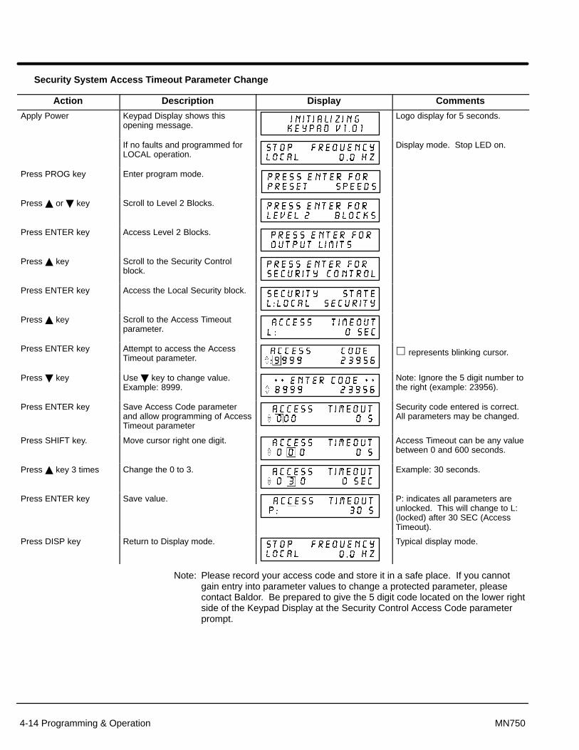
Security System Access T imeout Parameter Change
Action Description Display Comments
Apply Power Keypad Display shows thisopening message.
Logo display for 5 seconds.
If no faults and programmed forLOCAL operation.
Display mode. Stop LED on.
Press PROG key Enter program mode.
Press � or � key Scroll to Level 2 Blocks.
Press ENTER key Access Level 2 Blocks.
Press � key Scroll to the Security Controlblock.
Press ENTER key Access the Local Security block.
Press � key Scroll to the Access Timeoutparameter.
Press ENTER key Attempt to access the AccessTimeout parameter.
� represents blinking cursor.
Press � key Use � key to change value.Example: 8999.
Note: Ignore the 5 digit number tothe right (example: 23956).
Press ENTER key Save Access Code parameterand allow programming of AccessTimeout parameter
Security code entered is correct.All parameters may be changed.
Press SHIFT key. Move cursor right one digit. Access Timeout can be any valuebetween 0 and 600 seconds.
Press � key 3 times Change the 0 to 3. Example: 30 seconds.
Press ENTER key Save value. P: indicates all parameters areunlocked. This will change to L:(locked) after 30 SEC (AccessTimeout).
Press DISP key Return to Display mode. Typical display mode.
Note: Please record your access code and store it in a safe place. If you cannotgain entry into parameter values to change a protected parameter, pleasecontact Baldor. Be prepared to give the 5 digit code located on the lower rightside of the Keypad Display at the Security Control Access Code parameterprompt.

Programming & Operation 4-15MN750
SmartMotor Parameters
LEVEL 1 BLOCKS LEVEL 2 BLOCKSPreset Speeds Input Output Limits Process Control
Preset Speed #1 Operating Mode Min Output Freq Follow IN/OUT
Preset Speed #2 ANA CMD Select Max Output Freq Encoder Lines
Preset Speed #3 ANA CMD Inverse PK Current Limit
Preset Speed #4 ANA CMD Offset PWM Frequency Skip Frequency
Preset Speed #5 ANA CMD Gain Skip Freq #1
Preset Speed #6 ANA CMD Filter Custom Units Skip Band #1
Preset Speed #7 Decimal Places Skip Freq #2
Value At Speed Skip Band #2
Accel / Decel Rate Output Units of Measure Skip Freq #3
Accel Time #1 Opto Output #1 Skip Band #3
Decel Time #1 Zero Spd Set Pt Protection
S-Curve #1 At Speed Band External Trip Synchro Starts
Accel Time #2 Set Speed Point PWM vs TEMP Synchro–Starts
Decel Time #2 Overload Set PT Foldback Protect Sync Start Freq
S-Curve #2 Underload Set Pt Sync Scan V/F
ANA Volt Range Miscellaneous Sync Setup Time
Jog Settings Analog Out #1 Restart Auto/Man Sync Scan Time
Jog Speed Analog Scale #1 Restart Fault/Hr Sync V/F Recover
Jog Accel Time Restart Delay Sync Direction
Jog Decel Time Stability Comp
Jog S-Curve Time V/HZ and Boost Factory Settings Profile Run
Ctrl Base Freq Number of Cycles
Keypad Setup Torque Boost Security Control RP Restart Mode
Keypad Stop Key Dynamic Boost Security State SPD#1 Curve/Dir
Keypad Stop Mode Slip Comp Adj Access Timeout Profile Time #1
Keypad Run Fwd V/HZ Profile Access Code SPD#2 Curve/Dir
Keypad Run Rev Max Output Volts Profile Time #2
Keypad Jog Fwd Motor Data SPD#3 Curve/Dir
Keypad Jog Rev Motor Voltage Profile Time #3
Motor Rated Amp SPD#4 Curve/Dir
Motor Rated Spd Profile Time #4
Motor Rated Freq SPD#5 Curve/Dir
Motor Mag Amps Profile Time #5
SPD#6 Curve/Dir
Brake Adjust Profile Time #6
Resistor Ohms SPD#7 Curve/Dir
Resistor Watts Profile Time #7
DC Brake Voltage
DC Brake Freq
Brake On Stop
Brake On Rev
Stop Brake Time
Brake On Start
Start Brake Time

4-16 Programming & Operation MN750
Parameter Description The following control adjustments are available within the SmartMotor to allow customtailoring of the drive for particular applications. Table 4-1 and 4-2 provides a descriptionof each parameter block.
The tables in Appendix A list the location and possible values of the control adjustments.
Table 4-1 Parameter Block Definitions Level 1
Block Title Description
PRESETSPEEDS
7 preset speeds allow selection of 7 predefined motor operating frequencies. Each speed may be selected using external switches connected to J1-7, J1-8 and J1-9. For motor operation, a motor direction command must be given along with a preset speed command.
ACCEL/DECELRATE
Accel time is the number of seconds required for the motor to increase at a linear rate from 0Hz to thefrequency specified in the “Maximum Output Frequency” parameter in the Output Limits Level 2 blocks.
Decel time is the number of seconds required for the motor to decrease at a linear rate from the frequencyDecel time is the number of seconds required for the motor to decrease at a linear rate from the frequencyspecified in the “Maximum Output Frequency” parameter to 0Hz.
S-Curve is a percentage of the total Accel or Decel time and provides smooth starts and stops. Figure 4-2 illustrates how motor acceleration is changed using a 40% S-Curve.
S f SFigure 4 2 illustrates how motor acceleration is changed using a 40% S Curve. 0% represents no “S” and 100% represents full “S” with no linear segment.
Example: Maximum Output Frequency=100 Hz; Preset Speed = 50Hz, Accel Time=10 Sec. In this example, motor will be at speed 5 seconds after commanded because preset is half the max speed.
Note: Accel Time #1, Decel Time #1 and S-Curve #1 are related. Likewise, Accel Time #2, Decel Time#2 and S-Curve #2 are related. These relations can be used to control any Preset Speed orExternal Speed Command (Pot).External S eed Command (Pot).
Note: Since the motor uses rotor slip to produce motor torque, the motor speed may not change in alinear manner with the applied frequency. Accel, Decel and S-Curve values may be adjusted foryour applicationyour application.
Note: If faults (motor trips) occur during rapid Accel or Decel, selecting an S-curve may eliminate thefaults without affecting the overall ramp time.
JOG SETTINGS Jog Speed changes motor speed to the preset value for jog mode. To cause motor to operate at Jog Speedthe FWD or REV key must be pressed or external command Forward (J1-5) or Reverse (J1-6). The motorthe FWD or REV key must be ressed or external command Forward (J1-5) or Reverse (J1-6). The motorwill run at jog speed until FWD or REV key is released or external command signal is removed.
J A l Ti h th A l Ti t t l f j dJog Accel Time changes the Accel Time to a new preset value for jog mode.
Jog Decel Time changes the Decel Time to a new preset value for jog mode.Jog Decel Time changes the Decel Time to a new reset value for jog mode.
Jog S-Curve changes the S-Curve to a new preset value for jog mode.
Figure 4-2 S-Curve Example
Out
put
Fre
quen
cy
Accel Time0 MaxAccel S-Curves
20%
20%
0%Curve
40%Curve
Out
put
Fre
quen
cy
Decel Time0 MaxDecel S-Curves
20%
20%
0%Curve
40%Curve
Programming & Operation 4-17MN750
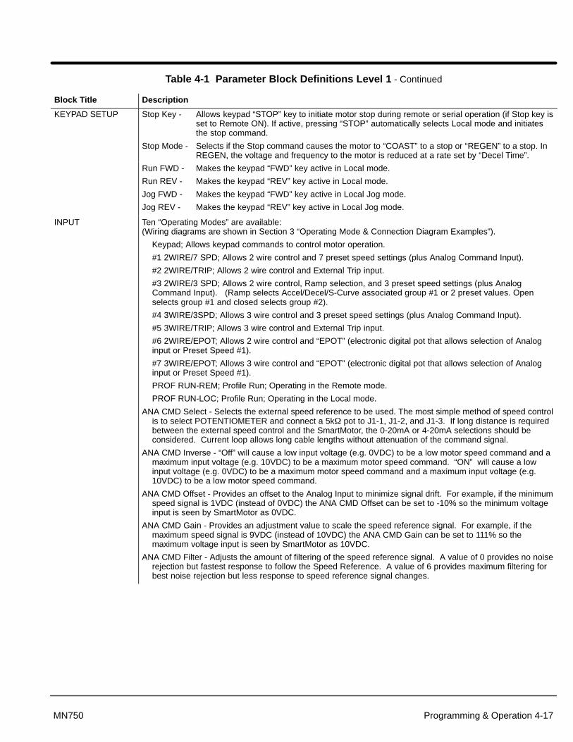
Table 4-1 Parameter Block Definitions Level 1 - Continued
Block Title Description
KEYPAD SETUP Stop Key - Allows keypad “STOP” key to initiate motor stop during remote or serial operation (if Stop key isset to Remote ON). If active, pressing “STOP” automatically selects Local mode and initiatesthe stop command.
Stop Mode - Selects if the Stop command causes the motor to “COAST” to a stop or “REGEN” to a stop. InREGEN, the voltage and frequency to the motor is reduced at a rate set by “Decel Time”., g q y y
Run FWD - Makes the keypad “FWD” key active in Local mode.
Run REV - Makes the keypad “REV” key active in Local mode.
Jog FWD - Makes the keypad “FWD” key active in Local Jog mode.
Jog REV - Makes the keypad “REV” key active in Local Jog mode.
INPUT Ten “Operating Modes” are available: (Wiring diagrams are shown in Section 3 “Operating Mode & Connection Diagram Examples”).
Keypad; Allows keypad commands to control motor operation.
#1 2WIRE/7 SPD; Allows 2 wire control and 7 preset speed settings (plus Analog Command Input).
#2 2WIRE/TRIP; Allows 2 wire control and External Trip input.
#3 2WIRE/3 SPD; Allows 2 wire control, Ramp selection, and 3 preset speed settings (plus AnalogCommand Input). (Ramp selects Accel/Decel/S-Curve associated group #1 or 2 preset values. Openselects group #1 and closed selects group #2).
#4 3WIRE/3SPD; Allows 3 wire control and 3 preset speed settings (plus Analog Command Input).
#5 3WIRE/TRIP; Allows 3 wire control and External Trip input.
#6 2WIRE/EPOT; Allows 2 wire control and “EPOT” (electronic digital pot that allows selection of Analoginput or Preset Speed #1).
#7 3WIRE/EPOT; Allows 3 wire control and “EPOT” (electronic digital pot that allows selection of Analoginput or Preset Speed #1).
PROF RUN-REM; Profile Run; Operating in the Remote mode.
PROF RUN-LOC; Profile Run; Operating in the Local mode.
ANA CMD Select - Selects the external speed reference to be used. The most simple method of speed controlis to select POTENTIOMETER and connect a 5k� pot to J1-1, J1-2, and J1-3. If long distance is requiredbetween the external speed control and the SmartMotor, the 0-20mA or 4-20mA selections should beconsidered. Current loop allows long cable lengths without attenuation of the command signal.
ANA CMD Inverse - “Off” will cause a low input voltage (e.g. 0VDC) to be a low motor speed command and amaximum input voltage (e.g. 10VDC) to be a maximum motor speed command. “ON” will cause a lowinput voltage (e.g. 0VDC) to be a maximum motor speed command and a maximum input voltage (e.g.10VDC) to be a low motor speed command.
ANA CMD Offset - Provides an offset to the Analog Input to minimize signal drift. For example, if the minimumspeed signal is 1VDC (instead of 0VDC) the ANA CMD Offset can be set to -10% so the minimum voltageinput is seen by SmartMotor as 0VDC.
ANA CMD Gain - Provides an adjustment value to scale the speed reference signal. For example, if themaximum speed signal is 9VDC (instead of 10VDC) the ANA CMD Gain can be set to 111% so themaximum voltage input is seen by SmartMotor as 10VDC.
ANA CMD Filter - Adjusts the amount of filtering of the speed reference signal. A value of 0 provides no noiserejection but fastest response to follow the Speed Reference. A value of 6 provides maximum filtering forbest noise rejection but less response to speed reference signal changes.

4-18 Programming & Operation MN750
Table 4-1 Parameter Block Definitions Level 1 - Continued
Block Title Description
OUTPUT OPTO OUTPUT #1 - One optically isolated digital output that has two operating states, ON or OFF. Thisoutput may be configured to any of 9 conditions as follows:
Condition Description
Ready - Active when power is applied and no faults are present.
Zero Speed - Active when output frequency to motor is below the value of the “Zero Spd Set Pt” Level 1Output parameter.
At Speed - Active when output frequency is within the speed range defined by the “At Speed Band”Level 1 Output parameter.
At Set Speed - Active when output frequency is at or above the “Set Speed Point” Level 1 Outputparameter.
Overload - Active if motor current increases above the Overload Set Pt value.
Underload - Active if motor current decreases below the Underload Set Pt value.
Keypad Control - Active when SmartMotor is in Local keypad control.
Fault - Active when a fault condition is present.
Drive On - Active when SmartMotor is “Ready” and commanded to operate the motor.
Reverse - Active when SmartMotor is running in reverse direction.
ZERO SPD SET PT - Sets the frequency at which the Zero Speed opto output becomes active (turns on).When the frequency (internal) is less than the ZERO SPD SET PT, the Opto Outputbecomes active. This is useful for when a motor brake is to interlock operation with amotor.
AT SPEED BAND - Sets the frequency band at which the At Speed opto output becomes active (turns on).When the frequency (internal) is within the band, the Opto Output becomes active. This isuseful when another machine must not start until the SmartMotor reaches operatingspeed.
SET SPEED POINT - Sets the frequency at which the Set Speed opto output becomes active (turns on).When the frequency (internal) is greater than the SET SPEED POINT, the Opto Outputbecomes active. This is useful when another machine must not start until the SmartMotorexceeds a predetermined speed.
OVERLOAD SET PT –
UNDERLOAD SET PT -
ANA VOLT RANGE - Sets the full scale output voltage range of the Analog Output to either 0-5 or 0-10 voltsto match the scale factor of an analog device.
ANALOG OUT#1 - One Analog output set by ANA VOLT RANGE parameter may be configured to representany of 7 conditions as follows:
Condition Description
Frequency - Represents the output frequency actually applied to the motor. 0VDC = 0Hz and 10VDC = Max Hz (slip frequency compensation not included). This is a representation ofthe actual output to the motor.
Freq Command - Represents the commanded output frequency. 0VDC = 0Hz and 10VDC = Max Hz. Thisis a representation of the commanded frequency, not actual motor frequency.
AC Current - Represents the RMS value of the output current actually applied to the motor. 0VDC = 0ARMS and 10VDC = Full load current (ARMS).
AC Voltage - Represents the RMS value of the output voltage actually applied to the motor.0VDC = 0VRMS and 10VDC = Full voltage output (VRMS).
Bus Voltage - Represents the bus voltage (5 or 10VDC full scale). For a 230VAC drive, full scale =400VAC input. For a 460VAC drive, full scale = 800VAC input.
ZEROCAL - Sets output voltage to 0VDC. Can be used to set zero on external meter.
100% CAL - Sets output voltage to 10VDC. Can be used to set full scale on external meter.
ANALOG SCALE #1 - Scale factor for the Analog Output voltage. Useful to set the zero value or full scalerange for external meters.

Programming & Operation 4-19MN750
Caution: Increasing the T orque Boost value may cause the motor to overheatat low speed.
Table 4-1 Parameter Block Definitions Level 1 - Continued
Block Title Description
V/HZ AND BOOST CTRL BASE FREQ - Sets the point on the V/Hz profile where the output voltage becomes constant regardlessof further increases in output frequency. This is the output frequency that the motorchanges from constant torque (or variable torque) to constant horsepower operation.
TORQUE BOOST - This value can be changed to increase or decrease the motor starting torque, This boostadjustment changes the output voltage from the normal value (defined by the V/Hz profile)by increasing or decreasing the starting output voltage by fixed values. Increasing theboost value may cause the motor to overheat. If adjustment is required, apply maximumload to the motor shaft. Increase the Torque Boost value until the shaft just starts torotate.
DYNAMIC BOOST - This value can be changed to increase or decrease the motor running torque, Thisboost adjustment changes the output voltage from the normal value (defined by the V/Hzprofile) by increasing or decreasing the output voltage per output frequency ratio.
SLIP COMP ADJ - This parameter allows adjustment for varying load conditions during normal operation.The Slip Comp Adjustment sets the maximum variation of output frequency under varyingload conditions. As the motor current increases toward 100% of Motor Rated Amps, thecontrol will increase the output frequency to compensate for motor slip.
V/HZ Profile - This parameter defines how much voltage will be applied to the motor in various segmentsof the output frequency range. The V/Hz values can adjust the amount of available torquefrom the motor at various speed points. 5 options are available: (See Figure 4-3)
Option Description
Linear - Used for constant torque applications such as conveyor systems.
9 Points - Factory set for optimum motor performance.
33% Square Law- Variable torque application preset profile.
67% Square Law- Variable torque application preset profile.
100% Square Law- Variable torque application preset profile.
MAX Output Volts - Sets the maximum output voltage available to the motor. In some cases, this value alongwith the CTRL Base Frequency can be adjusted to provide a wider constant torque rangeor wider constant horsepower speed range than is normally available from the motor.
LEVEL 2 BLOCK Enters level 2 block menu
Figure 4-3 Volts/Hz Profile
Max Output
Torque Boost
BaseFreq.
Output Frequency
Linear V/Hz Curve
Max Output
Torque Boost
BaseFreq.
Output Frequency
Square Law V/Hz Curve
Max Output
Torque Boost
BaseFreq.
Output Frequency
9 Point V/Hz Curve
Out
put V
olts
Out
put V
olts
Out
put V
olts
33% Square Law
100% Square Law
67% Square Law

4-20 Programming & Operation MN750
Table 4-2 Parameter Block Definitions Level 2
Block Title Description
OUTPUT LIMITS MIN Output Frequency - Minimum value in Hz of the frequency to be applied to the motor.
MAX Output Frequency - The maximum output frequency to the motor. This value may be exceeded slightly ifSlip Compensation is active.
PK Current Limit - The maximum output current to the motor. Values less than 100% are useful to limit motortorque that may damage driven equipment. Values of 101 to 150% can be sustained for 60 seconds andvalues between 151% and 200% can be sustained for 3 seconds.
PWM Frequency - The frequency that the output transistors are switched. PWM should be as low as possibleto minimize stress on the output transistors and motor windings. PWM frequency is also referred to as“Carrier” frequency.
CUSTOM UNITS Decimal Places - The number of decimal places of the Output Rate display on the Keypad display. This valuewill be automatically reduced for large values.
Value at Speed - The desired Output Rate value per motor RPM. The Output Rate is the number to the left ofthe “/” and the motor RPM is the number to the right of the “/”. See also, Units of Measure.
Units of Measure - The customized units of measure that are displayed with the Output Rate. To set the unitstext, first select the character by using the SHIFT key and use the � and � keys to scroll through theavailable character choices. If the desired character is not shown on the first line of the display, use theSHIFT key to move the cursor to the � and � arrow on the far left of the display. Once the cursor is on theUp/Down arrow special character, the arrow keys are used to select the character on the top line of thedisplay. Then select the next character. See also, Value at Speed.
PROTECTION External Trip - OFF - External Trip is Disabled.ON - If Operating Mode (Level 1 INPUT block parameter) is set to 2 Wire/Trip or 3 Wire/Trip and a normallyclosed contact at J1-9 is opened, an External Trip fault is generated and the SmartMotor will shut down.
PWM vs TEMP -OFF - PWM vs TEMP disabled.ON - If temperature of the control is too great, PWM frequency will automatically be reduced.
FOLDBACK PREVENT -OFF - FOLDBACK PREVENTION disabled.ON - Accel/Decel rate will automatically be extended to prevent overcurrent trips during rapid accelerationor overvoltage trips during rapid deceleration.
MISCELLANEOUS Restart Auto/Man - Manual - If a fault occurs, the SmartMotor must be manually reset to resume operation.Automatic - If a fault occurs, the SmartMotor will automatically reset to resume operation.
Restart Fault/Hr - The maximum number of automatic restart attempts before requiring a manual restart. Afterone hour without reaching the maximum number of faults or if power is turned off and on again, the faultcount is reset to zero.
Restart Delay - The amount of time allowed after a fault condition for an automatic restart to occur. Useful toallow sufficient time to clear a fault before restart is attempted.
Factory Settings - Restores factory settings for all parameter values. Select YES and press “ENTER” key torestore factory parameter values. The keypad Display will show “Operation Done” then return to “NO”when completed.

Programming & Operation 4-21MN750
Table 4-2 Parameter Block Definitions Level 2 Continued
Block Title Description
SECURITYCONTROL
Security State - Off - No security Access Code required to change parameter values.Local - Requires security Access Code to be entered before changes can be entered using the Keypad.Serial - Requires security Access Code to be entered before changes can be entered using the RS 485link.
Access Timeout - The time in seconds the security access remains enabled after leaving the programmingmode. If you exit and go back into the program Mode within this time limit, the security Access Code doesnot have to be re-entered. This timer starts when leaving the Program Mode (by pressing Display etc.).
Access Code - This code allows only those knowing the code to change secured parameter data.
Note: Please record your access code and store it in a safe place. If you cannot gain entry into parametervalues to change a protected parameter, please contact Baldor. Be prepared to give the 5 digit codelocated on the lower right side of the Keypad Display at the Security Control Access Code parameterprompt.
MOTOR DATA Motor Voltage - The rated voltage of the motor (listed on the rating plate). This is a view only parameter andcannot be changed.
Motor Rated Amps - The rated current of the motor (listed on the rating plate). If the motor current exceedsthis value for a period of time, an Overcurrent fault will occur. This value can only be decreased from theRated Amps value.
Motor Rated SPD - The rated speed of the motor (listed on the rating plate). If Motor Rated SPD = 1750 RPMand Motor Rated Freq = 60 Hz, the Keypad Display will show 1750 RPM at 60 Hz but 850 RPM at 30Hz.This is a view only parameter and cannot be changed.
Motor Rated Freq - The rated frequency of the motor (listed on the rating plate). This is a view only parameterand cannot be changed.
Motor Mag Amps - The motor magnetizing current value (listed on the rating plate). Also called no loadcurrent. This is a view only parameter and cannot be changed.
BRAKE ADJUST Resistor Ohms - The resistance value of the external dynamic braking resistor in ohms. Preset to 0 (nobraking). Refer to dynamic braking manual or call Baldor for additional information.
Resistor Watts - The power rating of the external dynamic braking resistor in watts. Preset to 0 (no braking).Refer to dynamic braking manual or call Baldor for additional information.
DC Brake Voltage - The voltage level that will be applied to the motor windings during DC injection braking.Higher percentage braking levels will cause the motor to have more braking torque available for stopping.For applications that require frequent Stops and Starts DC injection braking will cause additional motorheating. The maximum DC voltage available =1.414(Max Output Volts*).* Max Output Volts is a Level 1 V/Hz Block parameter.
DC Brake Freq - The output frequency at which DC injection braking begins. If this is less than the motoroperating frequency, after a stop or reverse command the motor speed will decrease by the Decel Timeparameter. When motor speed is reduced to a frequency equal to the DC Brake Freq DC voltage will besupplied to the motor for the amount of time specified by Stop Brake Time. If immediate DC injectionbraking is desired, this parameter should be set to a value greater than the motor operating frequency.
Brake on Stop - Turns on DC injection braking after a stop command.
Brake on Reverse - Turns on DC injection braking after a command to change motor rotation direction.
Stop Brake Time - The amount of time the DC injection braking is applied after a stop command if Brake onStop parameter = ON. If braking starts at a frequency less than set by the DC Brake Freq parameter,braking time is determined by the following formula:
Brake Time � Stop Brake Time � Output Freq at BrakingDC Brake Freq
�Brake on Start - Allows DC Injection Braking at the beginning of a run command to ensure the motor shaft is
not rotating. DC Injection Braking will automatically turn off and the motor will be commanded to accelerateto speed after the time specified by the Start Brake Time parameter.
Start Brake Time - The amount of time the DC injection braking is applied if Brake on Start parameter = ON.Start Brake Time should be just long enough to ensure the motor is not rotating at start up. Additionalmotor heating will occur in applications that require frequent starts and stops.
4-22 Programming & Operation MN750
Table 4-2 Parameter Block Definitions Level 2 Continued
Block Title Description
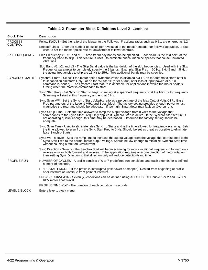
PROCESSCONTROL
Follow IN/OUT - Set the ratio of the Master to the Follower. Fractional ratios such as 0.5:1 are entered as 1:2.CONTROL
Encoder Lines - Enter the number of pulses per revolution of the master encoder for follower operation. Is alsoused to set the master pulse rate for downstream follower controls.
SKIP FREQUENCY Skip Frequency #1, #2, and #3 - Three frequency bands can be specified. Each value is the mid point of thefrequency band to skip. This feature is useful to eliminate critical machine speeds that cause unwantedvibrations.
Skip Band #1, #2, and #3 - The Skip Band value is the bandwidth of the skip frequencies. Used with the SkipFrequency parameter to completely specify the 3 bands. Example, Skip Freq = 20 Hz, Skip Band = 5 Hz.;the actual frequencies to skip are 15 Hz to 25Hz. Two additional bands may be specified.
SYNCHRO STARTS Synchro–Starts - Select if the motor speed synchronization is disabled “OFF”, on for automatic starts after afault condition “Restarts Only”; or on for “All Starts” (after a fault, after loss of input power, or a runcommand is issued). The Synchro Start feature is desirable for applications in which the motor shaft isturning when the motor is commanded to start.
Sync Start Freq - Set Synchro Start to begin scanning at a specified frequency or at the Max motor frequency.Scanning will start at this frequency and end at 0 Hz.
Sync Scan V/F - Set the Synchro Start Volts/Hz ratio as a percentage of the Max Output Volts/CTRL BaseFreq parameters of the Level 1 V/Hz and Boost block. The factory setting provides enough power to justmagnetize the rotor and should be adequate. If too high, SmartMotor may fault on Overcurrent.
Sync Setup Time - Sets the time allowed to ramp the output voltage from 0 volts to the voltage thatcorresponds to the Sync Start Freq. Only applies if Synchro Start is active. If the Synchro Start feature isnot operating quickly enough, this time may be decreased. Otherwise the factory setting should beadequate.
Sync Scan Time - Used to eliminate false Synchro Starts and is the time allowed for frequency scanning. Setsthe time allowed to scan from the Sync Start Freq to 0 Hz. Should be set as great as possible to eliminatefalse Synchro Starts.
Sync V/F Recover - Sets the ramp time to increase the output voltage from the voltage that corresponds to theSync Start Freq to the normal motor output voltage. Should be low enough to minimize Synchro Start timewithout causing a fault on Overcurrent.
Sync Direction - Selects if the Synchro Start will begin scanning for motor rotational frequency in forward only,reverse only, or both forward and reverse. If the application requires only one direction of motor rotation,then setting Sync Direction to that direction only will reduce detection/sync time.
PROFILE RUN NUMBER OF CYCLES - A profile consists of 0 to 7 predefined run conditions and each extends for a definednumber of seconds.
RP RESTART MODE - If the profile is interrupted (lost power or stopped), Restart from beginning of profileafter interrupt or Continue from point of interrupt.
SPD#1-7 CURVE/DIR - Seven (7) conditions can be defined using ACCEL/DECEL curve 1 or 2 and FWD orREV motor shaft travel.
PROFILE TIME #1-7 - The duration of each condition in seconds.
LEVEL 1 BLOCK Enters level 1 block menu

Section 3Receiving & Installation
Receiving & Installation 3-1MN750
Receiving & Inspection The SmartMotor is thoroughly tested at the factory and carefully packaged forshipment. When you receive your drive, there are several things you should doimmediately.
1. Observe the condition of the shipping container and report any damageimmediately to the commercial carrier that delivered your control.
2. Verify that the part number of the control you received is the same as the partnumber listed on your purchase order.
3. If the control is to be stored for several weeks before use, be sure that it isstored in a location that conforms to published storage specifications. (Refer toSection 6 of this manual).
Overview This section describes the proper mounting and wiring procedure of the BaldorSmartMotor . If problems arise after installation, please refer to the Diagnostics andTroubleshooting section of this manual.
Location and Mounting Select a mounting surface for the SmartMotor that allows installation using the mountingholes provided. The area selected should allow for free air circulation around the control.Provide at least two inches of clearance on all sides for maximum cooling efficiency.
Caution: Do not mount the SmartMotor with the control cover in the downposition. The cover must face up or to one side to keep liquids andcontaminants away from the heatsink.
Caution: A void locating the SmartMotor immediately above or beside heatgenerating equipment, or directly below water or steam pipes.
Vibration Considerations
Excessive vibration can cause failure of the control. If control is subjected to vibrationlevels greater than 1G at 10 to 60 Hz, the control must be shock mounted.
Altitude Derating
Ratings apply to 3300 feet (1000 meters) altitude with no derating required. Forinstallations at higher altitudes derate the continuous and peak output currents of thecontrol by 2% for each 1000 feet above 3300 feet.
Temperature Derating
Control ratings apply to 40°C. Derate output by 2% per °C above 40°C. Maximumambient is 55°C.
Wiring Consideration
All logic and control connections are made at the 15 pin J1 connector shown in Figure3-1. All external wires for the SmartMotor should be run in a conduit that is separate fromall other wiring. Be sure to use Class 1 wiring. The use of shielded wire is recommendedfor all control wiring.

3-2 Receiving & Installation MN750
AC Power Considerations Interconnection wiring is required between components such as the AC power source,SmartMotor, optional operator control stations, etc. Wire connectors that are used mustbe the correct size and installed using the crimp tool specified by the connectormanufacturer.
Caution: Do not use power factor correction capacitors on the input powerlines to the SmartMotor. Damage to the control may result if theyare used.
AC Line Impedance The Baldor SmartMotor requires a minimum line impedance of 1% (voltage drop at theinput is 1% minimum at rated input current). If the incoming power line does not have aminimum of 1% impedance, a line reactor can be used to provide the needed impedancein most cases. Use the following formula to calculate the size of the line reactor you mustprovide. Line reactors are available from Baldor.
Note: Continuous input current requirement is provided in Table 3-1.
(VL�L x 0.01)(l x 1.732 x 377)
L=
Where: L = minimum line inductance in HenriesVL-L = input voltage measured from line to line 0.01= desired percentage of impedance
I = the continuous input current rating of the control
1.732 = square root of three377 = constant used if the input frequency
is 60 Hz. Use 314 if the Input frequencyis 50 Hz.
Line reactors serve several purposes which include:
1. Minimize voltage spikes from the power line that may otherwise cause thecontrol to trip on over voltage spikes.
2. Minimize voltage harmonics from the control to the power line.
3. Provide additional short circuit capability at the control.

Receiving & Installation 3-3MN750
Table 3-1 - SmartMotor Wire Size and Protection Devices
Catalog Max Constant Input Wire Input Breaker (240V=TEB 460V=TED)
Input Fuses Fast Acting (230V=KTN 460V=KTS)
Input Fuses Time Delay (230V=FRN 460V=FRS)Catalog
NumberMax Constant
Torque HP AWG mm 2(240V=TEB, 460V=TED)
Amps(230V=KTN, 460V=KTS)
Amps(230V=FRN, 460V=FRS)
AmpsNEMA 1 – 230 Volt Input
CSM3546T - 2 1 14 2.08 7 6 5
CSM3558T - 2 2 14 2.08 15 12 9
CSM3611T - 2 3 14 2.08 15 15 12
CSM3615T - 2 5 12 3.31 20 25 20
CSM3710T - 2 7.5 10 5.26 30 35 30
CSM3714T - 2 10 10 5.26 40 45 35
NEMA 1 – 460 Volt Input
CSM3546T - 4 1 14 2.08 3 3 2.5
CSM3558T - 4 2 14 2.08 7 5 4.5
CSM3611T - 4 3 14 2.08 7 8 6.3
CSM3615T - 4 5 14 2.08 15 12 10
CSM3710T - 4 7.5 14 2.08 15 17.5 15
CSM3714T - 4 10 14 2.08 20 20 17.5
NEMA 4 – 230 Volt Input
CWDSM3546T - 2 1 14 2.08 7 6 5
CWDSM3558T - 2 2 14 2.08 15 12 9
CWDSM3611T - 2 3 14 2.08 15 15 12
CWDSM3615T - 2 5 12 3.31 20 25 20
CWDSM3710T - 2 7.5 10 5.26 30 35 30
CWDSM3714T - 2 10 10 5.26 40 45 35
NEMA 4 – 460 Volt Input
CWDSM3546T - 4 1 14 2.08 3 3 2.5
CWDSM3558T - 4 2 14 2.08 7 5 4.5
CWDSM3611T - 4 3 14 2.08 7 8 6.3
CWDSM3615T - 4 5 14 2.08 15 12 10
CWDSM3710T - 4 7.5 14 2.08 15 17.5 15
CWDSM3714T - 4 10 14 2.08 20 20 17.5
Note: All wire sizes are based on 75° C copper wire. Smaller gauge wire that has agreater temperature rating may be used per NEC and local codes.Recommended breakers/fuses are based on 25° C ambient, MAX continuousoutput current and no harmonic current.
Protective Devices Be sure a suitable input power protection device is installed. Use the recommendedcircuit breaker or fuses listed in Table 3-1. Input and output wire size is based on the useof copper conductor wire rated at 75 °C. The table is specified for SmartMotors that use aNEMA B motor design.
Circuit Breaker: 3 phase, thermal magnetic. Equal to GE type THQ or TEB for 230 VAC or GE type TED for 460 VAC.
Fast Action Fuses: Buss KTN on 230 VAC or Buss KTS on 460 VAC.
Very Fast Action: Buss JJN on 230 VAC, orBuss JJS on 460 VAC.
Time Delay Fuses: Buss FRN on 230 VAC or Buss FRS on 460 VAC.
Power Disconnect A power disconnect should be installed between the input power service and theSmartMotor for a fail safe method to disconnect power. The SmartMotor will remain in apowered-up condition until all input power is removed from the control and the internalbus voltage is depleted.

3-4 Receiving & Installation MN750
AC Power Connections Figures 3-1 and 3-2 show the SmartMotor connections.
WARNING: Do not attempt to service this equipment while bus voltage ispresent within the control. Remove input power and wait at least 5minutes for the residual voltage in the bus capacitors to dissipate.
1. Be sure drive operation is terminated and secured.
2. Remove all power sources from the motor.
3. Remove cover. Remove the four (4) screws that secure the control cover andremove cover.
4. Connect the incoming AC power wires from the protection devices to L1, L2and L3 at the Main Circuit Terminals (torque to 11 lb-in). The phase rotation isnot important as the control is not phase sensitive.
5. Connect earth ground to the “Power Ground”. Be sure to comply with localcodes (torque to 50 lb-in).
6. Install the control cover. Place the cover on the control and install & tighten thefour (4) screws that secure the control cover.
DC Power Connections Operation of the SmartMotor using a DC power source is possible. The DC power leadsshould be connected to L1 and L2 using disconnect and protection devices. The DCvoltage level must be equivalent to the full wave rectified value of the nominal rated ACinput voltage. For example, 280 to 340 VDC (for a 230 VAC rating) and 535 to 680 VDC(for a 460 VAC rating). Protective devices should be sized using the equivalent ACratings.

Receiving & Installation 3-5MN750
Figure 3-1 Baldor SmartMotor 35 Frame Connections
12
3456789
101112
131415
Analog GroundAnalog Input
Pot Reference (10VDC)Analog OutputOpto Input #1Opto Input #2Opto Input #3Opto Input #4Opto Input #5Opto Input CommonDigital CommonDigital Output
RS485 (A)RS485 (GND)RS485 (B)
L1L2
L3T
1T
2T
3
KeypadConnector
Terminal tightening torque is11 lb-in (1.2 Nm) maximum.
POWER GROUNDTerminal tightening torque is50 lb-in (5.6 Nm) maximum.
GTerminal tighteningtorque is 2.2 lb–in(0.25 Nm)maximum.
J1
Red LEDSteady ON= FaultFlashing=Operating Mode
Green LEDBlinking=Microprocessor
is running
Red LEDON= Bus Voltage Present
J2
J3
Figure 3-2 Baldor SmartMotor 36/37 Frame Connections
POWER GROUNDTerminal tightening torque is50 lb-in (5.6 Nm) maximum.
GRed LEDON=Bus Voltage Present
B–
B+
L3L2
L1
J5
T3 T2 T1
123456789
101112
131415
Analog GroundAnalog InputPot Reference Analog OutputOpto Input #1Opto Input #2Opto Input #3Opto Input #4Opto Input #5Opto Input CommonDigital CommonDigital Output
RS485 (A)RS485 (GND)RS485 (B)
Terminal tighteningtorque is 2.2 lb–in(0.25 Nm) maximum.
J1
J2Red LEDSteady ON= FaultFlashing=Operating Mode
Green LEDBlinking= Microprocessor
is running
KeypadConnector

3-6 Receiving & Installation MN750
Installing Optional ItemsDynamic Braking (DB) Hardware If the application requires dynamic braking capability, an optional external
braking assembly or kit may be required. Please contact Baldor for availability andselection of DB assemblies.
Optional Remote Keypad Mounting The optional keypad may be remotely mounted using the optional Baldorkeypad extension cable. The keypad assembly comes complete with the screws andgasket required to mount it to an enclosure. When the keypad is properly mounted to aNEMA Type 4 enclosure, it retains the Type 4 indoor rating.
Tools Required:
• Drill motor, center punch, tap handle, screwdrivers (Phillips and straight) andcrescent wrench.
• 8-32 tap and #29 drill bit.
• 1-1/4″ standard knockout punch (1-11/16″ nominal diameter).
• RTV sealant.
• (4) 8-32 nuts and lock washers.
• Extended 8-32 screws (socket fillister) are required if the mounting surface isthicker than 12 gauge and is not tapped (clearance mounting holes).
• Remote keypad mounting template. (See Appendix B for template. Tear outcopy is included at the end of this manual).
Mounting Instructions: (See Appendix B)For tapped mounting holes
1. Locate a flat mounting surface that is a minimum of 4″ wide x 5.5″ high.Material should be sufficient thickness (14 gauge minimum).
2. Place the template on the mounting surface or mark the holes as shown on thetemplate.
3. Accurately center punch the 4 mounting holes (marked A) and the largeknockout (marked B).
4. Drill four #29 mounting holes (A). Thread each hole using an 8-32 tap.
5. Locate the 1-1/4″ knockout center (B) and punch using the manufacturersinstructions.
6. Debur knockout and mounting holes making sure the panel stays clean and flat.
7. Apply RTV to the 4 holes marked (A).
8. Assemble the keypad to the panel. Use 8–32 screws, nuts and lock washers.
9. From the inside of the panel, apply RTV over each of the four mounting screwsand nuts. Cover a 3/4″ area around each screw while making sure to completelyencapsulate the nut and washer.

Receiving & Installation 3-7MN750
Analog Input and OutputAnalog Input An analog input is available at J1-1, J1-2 and J1-3. This input is used with a 5k� pot as
a speed command. See Figure 3-3.
1. Be sure drive operation is terminated and secured.
2. Remove all power sources from the motor. Wait at least 5 minutes beforeproceeding to step 3.
3. Remove cover. Remove the four (4) screws that secure the control cover andremove cover.
4. Connect the wires from the 5k� pot as shown in Figure 3-3. One end of the potis connected to J1-1 (analog ground) and the other end is connected to J1-3(reference voltage).
5. Connect the wiper of the pot to J1-2. The voltage across terminals J1-1 andJ1-2 is the speed command input.
6. Install the control cover. Place the cover on the control and install & tighten thefour (4) screws that secure the control cover.
When using a potentiometer as the speed command, process feedback or setpointsource, the ANA CMD SELECT parameter of the Level 1 Input block must be set to“POTENTIOMETER”.
Note: An absolute 0-5VDC or 0-10VDC speed command signal may be connectedacross J1-1 and J1-2 instead of a 5k� pot. The ANA CMD SELECTparameter of the Level 1 block must be set to “0-5 Volts” or “0-10 Volts”.
Figure 3-3 Analog Input and Output
Analog Ground
Analog Input 1
Pot Reference
Analog Output
Command Pot or
0-5/0-10VDC (Across J1-1 and J1-2)
5k�
Figure 3-4 Analog 0-20 mA or 4-20 mA Input
Analog Ground
Analog Input 1
Pot Reference
Analog Output
0 -20 mA or4 -20 mA Input
(Across J1-1 and J1-2)
When using the 0-20 mA or 4-20 mA Input as the speed command, process feedback orsetpoint source, the ANA CMD SELECT parameter of the Level 1 block must be set to “0to 20 mA or 4 to 20 mA”. See Figure 3-4.

3-8 Receiving & Installation MN750
Analog Output One programmable analog output is provided at J1-4. See Figure 3-3 and 3-5. Thereturn for this output is J1-1 analog ground. This output is scaled 0-5/0-10 VDC (1mAmaximum output current) and can be used to provide real-time status of various controlconditions.
1. Be sure drive operation is terminated and secured.
2. Remove all power sources from the motor. Wait at least 5 min. beforeproceeding to step 3.
3. Remove cover. Remove the four (4) screws that secure the control cover andremove cover.
4. Connect the Output #1 wires to J1-4 and J1-1. This output is programmed inthe Level 1 Output block.
5. Install the control cover. Place the cover on the control and install & tighten thefour (4) screws that secure the control cover.
The Analog Output condition is programmed in the Level 1 Output block.
Figure 3-5 Analog Output Connection
Analog Ground
Analog Output
External Trip Input Terminal J1-9 is available for connection to a normally closed thermostat or overloadrelay in two operating modes (2 Wire/Trip or 3 Wire/Trip). The thermostat or overloadrelay should be a dry contact type with no power available from the contact. If the motorthermostat or overload relay activates (opens) the control will automatically shut downand give an External Trip fault. See Figure 3-6.
1. Be sure drive operation is terminated and secured.
2. Remove all power sources from the motor. Wait at least 5 minutes beforeproceeding to step 3.
3. Remove cover. Remove the four (4) screws that secure the control cover andremove cover.
4. Connect the External Trip Input wires to J1-9 and J1-10 (input common).
5. Install the control cover. Place the cover on the control and install & tighten thefour (4) screws that secure the control cover.
To activate the External Trip input, the External Trip parameter in the Level 2 ProtectionBlock must be set to “ON”.
Figure 3-6 External Trip Input
9
10
J1
External Trip
Input Common

Receiving & Installation 3-9MN750
Opto Isolated Inputs and OutputOpto-isolated Inputs Five Opto Isolated inputs are provided. Contact closure to the Input Common at J1-10
activates the input. See Figure 3-7.
1. Be sure drive operation is terminated and secured.
2. Remove all power sources from the motor. Wait at least 5 minutes beforeproceeding to step 3.
3. Remove cover. Remove the four (4) screws that secure the control cover andremove cover.
4. Connect the OPTO INPUT wires as follows:(See Figure 3-7.)
J1-5 Input #1 (Forward)J1-6 Input #2 (Reverse)J1-7 Input #3J1-8 Input #4J1-9 Input #5J1-10 Input Common
5. Install the control cover. Place the cover on the control and install & tighten thefour (4) screws that secure the control cover.
The Opto Input mode is programmed in the Level 1 Input block.
Figure 3-7 Opto Input Configurations
6
7
8
9
10
Opto Input 2
Opto Input 3
Opto Input 4
Opto Input 5
J1
5Opto Input 1

3-10 Receiving & Installation MN750
Opto-Isolated Output One programmable Opto-isolated output is available at terminals J1-12 (J1-11 Common).See Figure 3-8. It may be configured for sinking or sourcing 60 mA. The maximumvoltage from opto output to common when active is 1.0 VDC (TTL compatible).
If the opto output is used to directly drive a relay, a flyback diode rated at 1A, 100 Vminimum (1N4002) should be connected across the relay coil.
1. Be sure drive operation is terminated and secured.
2. Remove all power sources from the motor. Wait at least 5 minutes beforeproceeding to step 3.
3. Remove cover. Remove the four (4) screws that secure the control cover andremove cover.
4. Connect the external relay to the Opto output at J1-12 and J1-11 as shown inFigure 3-8.
5. Install the control cover. Place the cover on the control and install & tighten thefour (4) screws that secure the control cover.
The Opto Output condition is programmed in the Level 1 Output block.
Figure 3-8 Opto-isolated Output Configurations
11
12
Using External Supply(Sinking the Relay Current)
OptionalCustomerSupplied
Relay
Customer Supplied 10VDC to 30VDC Source
+
–

Receiving & Installation 3-11MN750
Operating Mode & Connection Diagram Examples Ten operating modes are available in the SmartMotor Series. These operating modesdefine the basic drive setup and the operation of the input and output terminals. Theseoperating modes are selected by programming the Operating Mode parameter in theLevel 1 Input Block. Available operating modes include:
Note: Contact Baldor factory to change operating modes from the terminal strip.
• Keypad (Figure 3-9)
• 2 Wire, 7 Speed (Figure 3-10)
• 2 Wire, Trip (Figure 3-11)
• 2 Wire, 3 Speed (Figure 3-12)
• 3 Wire, 3 Speed (Figure 3-13)
• 3 Wire, Trip (Figure 3-14)
• 2 Wire, Electronic Pot (Figure 3-15)
• 3 Wire, Electronic Pot (Figure 3-16)
• Profile Run Remote (Figure 3-17)
• Profile Run Local (Figure 3-18)
Keypad Operating Mode
Figure 3-9 Keypad Operating Mode
1
2
3
4
5
6
7
8
9
10
11
12
13
14
15
J1
Analog Ground
Analog Output
External Trip
Digital Output Common
Digital Output
RS485B
RS485 GND
RS485A
Input Common
J1-9 OPEN causes an external trip to be received by control. The SmartMotor is thendisabled and the optional Keypad Display will indicate an EXTERNAL TRIP occurred. (Iflevel 2 Protection block is programmed “ON”).

3-12 Receiving & Installation MN750
#1, 2 Wire 7 Speed Operating Mode
Figure 3-10 2 Wire 7 Speed Operating Mode
1
2
3
4
5
6
7
8
9
10
11
12
13
14
15
J1
Analog Ground
Analog Input
Pot Reference (10VDC)
Analog Output
Forward
Reverse
Speed Select #1
Speed Select #2
Speed Select #3
Input Common
Digital Output Common
Digital Output
RS485B
RS485 GND
RS485A
CommandPot 5k�
+
–User
5-30VDC
J1-5 CLOSED operates the motor in the forward direction.
J1-6 CLOSED operates the motor in the reverse direction.
J1-7 Speed Select (See Table 3-2).
J1-8 Speed Select (See Table 3-2).
J1-9 Speed Select (See Table 3-2).
Note: For modes without a Fault Reset input, a fault can be cleared if Forward andReverse switches are simultaneously closed and held for 2 seconds.
Note: The Analog Input (J1-2 & J1-1) is selected if all switches are open.
Table 3-2 Switch Truth Table for 2 Wire 7 Speed Mode
Function J1-7 J1-8 J1-9Analog Input Open Open Open
Preset Speed #1 Closed Open OpenPreset Speed #2 Closed Closed OpenPreset Speed #3 Closed Closed ClosedPreset Speed #4 Closed Open ClosedPreset Speed #5 Open Open ClosedPreset Speed #6 Open Closed ClosedPreset Speed #7 Open Closed Open

Receiving & Installation 3-13MN750
#2, 2 Wire External Trip Operating Mode
Figure 3-11 2 Wire External Trip Operating Mode
1
2
3
4
5
6
7
8
9
10
11
12
13
14
15
J1
Analog Ground
Analog Input
Pot Reference (10VDC)
Analog Output
Coast
Fault Reset
External Trip
Digital Output Common
Digital Output
RS485B
RS485 GND
RS485A
CommandPot 5k�
+
–User
5-30VDC
Forward
Reverse
Input Common
J1-5 CLOSED operates the motor in the forward direction.
J1-6 CLOSED operates the motor in the reverse direction.
J1-7 CLOSED allows motor to coast (no braking).
J1-8 CLOSED to reset fault condition.
J1-9 OPEN causes an external trip to be received by control. The SmartMotor is thendisabled and the optional Keypad Display will indicate an EXTERNAL TRIP occurred. (Iflevel 2 Protection block is programmed “ON”).

3-14 Receiving & Installation MN750
#3, 2 Wire 3 Speed Operating Mode
Figure 3-12 2 Wire 3 Speed Operating Mode
Speed Select #1
Speed Select #2
1
2
3
4
5
6
7
8
9
10
11
12
13
14
15
J1
Analog Ground
Analog Input
Pot Reference (10VDC)
Analog Output
Accel/Decel Group Select
Digital Output Common
Digital Output
RS485B
RS485 GND
RS485A
CommandPot 5k�
+
–User
5-30VDC
Forward
Reverse
Input Common
J1-5 CLOSED operates the motor in the forward direction.
J1-6 CLOSED operates the motor in the reverse direction.
J1-7 CLOSED selects Accel/Decel group #2.OPENED selects Accel/Decel group #1.
J1-8 Speed Select (See Table 3-3).
J1-9 Speed Select (See Table 3-3).
Note: For modes without a Fault Reset input, a fault can be cleared if Forward andReverse switches are simultaneously closed and held for 2 seconds.
Note: The Analog Input (J1-2 & J1-1) is selected if all switches are open.
Table 3-3 Switch Truth Table for 2 Wire 3 Speed Mode
Function J1-8 J1-9Analog Input Open Open
Preset Speed #1 Closed OpenPreset Speed #2 Closed ClosedPreset Speed #3 Open Closed

Receiving & Installation 3-15MN750
#4, 3 Wire 3 Speed Operating Mode
Figure 3-13 3 Wire 3 Speed Operating Mode
Speed Select #1
Speed Select #2
1
2
3
4
5
6
7
8
9
10
11
12
13
14
15
J1
Analog Ground
Analog Input
Pot Reference (10VDC)
Analog Output
Stop
Digital Output Common
Digital Output
RS485B
RS485 GND
RS485A
CommandPot 5k�
+
–User
5-30VDC
Forward (Momentary)
Reverse (Momentary)
Input Common
J1-5 Momentary CLOSED operates the motor in the forward direction.
J1-6 Momentary CLOSED operates the motor in the reverse direction.
J1-7 When OPEN commands motor to stop.
J1-8 Speed Select (See Table 3-4)
J1-9 Speed Select (See Table 3-4)
Note: For modes without a Fault Reset input, a fault can be cleared if Forward andReverse switches are simultaneously closed and held for 2 seconds.
Note: The Analog Input (J1-2 & J1-1) is selected if all switches are open.
Table 3-4 Switch Truth Table for 3 Wire 3 Speed Mode
Function J1-8 J1-9Analog Input Open Open
Preset Speed #1 Closed OpenPreset Speed #2 Closed ClosedPreset Speed #3 Open Closed

3-16 Receiving & Installation MN750
#5, 3 Wire External Trip Operating Mode
Figure 3-14 3 Wire External Trip Operating Mode
Fault Reset
External Trip
1
2
3
4
5
6
7
8
9
10
11
12
13
14
15
J1
Analog Ground
Analog Input
Pot Reference (10VDC)
Analog Output
Stop
Digital Output Common
Digital Output
RS485B
RS485 GND
RS485A
CommandPot 5k�
+
–User
5-30VDC
Forward (Momentary)
Reverse (Momentary)
Input Common
J1-5 Momentary CLOSED operates the motor in the forward direction.
J1-6 Momentary CLOSED operates the motor in the reverse direction.
J1-7 When OPEN commands motor to stop.
J1-8 CLOSED to reset fault condition.
J1-9 OPEN causes an external trip to be received by control. The SmartMotor is thendisabled and the optional Keypad Display will indicate an EXTERNAL TRIP occurred. (Iflevel 2 Protection block is programmed “ON”).

Receiving & Installation 3-17MN750
#6, 2 Wire Electronic Pot Operating Mode
Figure 3-15 2 Wire Electronic Pot Operating Mode
Speed Select #1
1
2
3
4
5
6
7
8
9
10
11
12
13
14
15
J1
Analog Ground
Analog Input
Pot Reference (10VDC)
Analog Output
Increase
Decrease
Digital Output Common
Digital Output
RS485B
RS485 GND
RS485A
+
–User
5-30VDC
Forward
Reverse
Input Common
J1-5 CLOSED operates the motor in the forward direction.
J1-6 CLOSED operates the motor in the reverse direction.
J1-7 OPENED selects Electronic PotentiometerCLOSED selects Preset Speed #1 (See Table 3-5)
J1-8 Momentary CLOSED increase motor speed while contact is closed.
J1-9 Momentary CLOSED decrease motor speed while contact is closed.
Note: For modes without a fault reset input, a fault can be cleared if forward andreverse switches are simultaneously closed and held for 2 seconds.
Table 3-5 Switch Truth Table for 2 Wire Electronic Pot Mode
Function J1-7Electronic Potentiometer (EPOT) Open
Preset Speed #1 Closed

3-18 Receiving & Installation MN750
#7, 3 Wire, Electronic Pot Operating Mode
Figure 3-16 3 Wire, Electronic Pot Operating Mode
Increase
Decrease
1
2
3
4
5
6
7
8
9
10
11
12
13
14
15
J1
Analog Ground
Analog Input
Pot Reference (10VDC)
Analog Output
Stop
Digital Output Common
Digital Output
RS485B
RS485 GND
RS485A
+
–User
5-30VDC
Forward (Momentary)
Reverse (Momentary)
Input Common
J1-5 Momentary CLOSED operates the motor in the forward direction.
J1-6 Momentary CLOSED operates the motor in the reverse direction.
J1-7 When OPEN commands motor to stop.
J1-8 Momentary CLOSED increase motor speed while contact is closed.
J1-9 Momentary CLOSED decrease motor speed while contact is closed.
Note: For modes without a Fault Reset input, a fault can be cleared if Forward andReverse switches are simultaneously closed and held for 2 seconds.

Receiving & Installation 3-19MN750
Profile Run Remote Operating Mode
Figure 3-17 Profile Run Remote Operating Mode
Increase
Decrease
1
2
3
4
5
6
7
8
9
10
11
12
13
14
15
J1
Analog Ground
Analog Input
Pot Reference (10VDC)
Analog Output
Stop
Digital Output Common
Digital Output
RS485B
RS485 GND
RS485A
+
–User
5-30VDC
Forward
Reverse
Input Common
J1-5 CLOSED allows the motor to continue the profile. When closed, the profile will resumein the direction and speed of the profile (may be forward or reverse).
J1-6 CLOSED allows the motor to continue the profile. When closed, the profile will resumein the direction and speed of the profile (may be forward or reverse).
Note: For modes without a Fault Reset input, a fault can be cleared if Forward and Reverseswitches are simultaneously closed and held for 2 seconds.

3-20 Receiving & Installation MN750
Profile Run Local Operating Mode
Figure 3-18 Profile Run Local Operating Mode
Increase
Decrease
1
2
3
4
5
6
7
8
9
10
11
12
13
14
15
J1
Analog Ground
Analog Input
Pot Reference (10VDC)
Analog Output
Stop
Digital Output Common
Digital Output
RS485B
RS485 GND
RS485A
+
–User
5-30VDC
Forward (Momentary)
Reverse (Momentary)
Input Common
Analog and Digital outputs are active but operation is controlled by the keypad in thismode. No input switches are recognized.

Receiving & Installation 3-21MN750
Pre-Operation ChecklistCheck of Electrical Items
CAUTION: After completing the installation but before you apply power , besure to check the following items.
1. Verify AC line voltage at source matches the SmartMotor rating.
2. Inspect all power connections for accuracy, workmanship, tightness andcompliance to codes.
3. Verify SmartMotor is grounded to earth ground.
4. Check all signal wiring for accuracy.
5. Be certain all brake coils, contactors and relay coils have noise suppression.This should be an R-C filter for AC coils and reverse polarity diodes for DCcoils. MOV type transient suppression is not adequate.
Check of Motor and Coupling
1. Verify freedom of motion of the motor shaft.
2. Verify that motor couplings are tight without backlash.
3. Verify the holding brakes, if any, are properly adjusted to fully release and set tothe desired torque value.
Temporary Application of Power
1. Check all electrical and mechanical connections before applying power to theSmartMotor.
2. Verify that control logic inputs at the J1 connector are proper.
3. Temporarily apply power and observe that the bus power indicator is on or thatthe optional keypad display is on (if Keypad is connected). If this indicationdoes not occur, check all connections and verify input voltage. If fault indicationoccurs, refer to the troubleshooting section of this manual.
4. Disconnect all power from the SmartMotor.

3-22 Receiving & Installation MN750
Minimum Required Parameter Settings and Control Set-up Checklist
If you are familiar with programming Baldor controls continue with the following steps. If not, proceed to the programming section of this manual before applying power to thedrive.
WARNING: Make sure that unexpected operation of the motor shaft during startup will not cause injury to personnel or damage to equipment.
Note: This list is the minimum program parameters required for operation of thecontrol for initial start-up.
1. Be sure drive operation is terminated and secured.
2. Remove all power sources from the motor. Wait at least 5 minutes beforeproceeding to step 3.
3. Remove cover. Remove the four (4) screws that secure the control cover andremove cover.
4. Connect the optional Keypad to the Keypad Connector (Figure 3-1). Run thekeypad wires through the conduit to motor case.
5. Install the control cover. Place the cover on the control and install & tighten thefour (4) screws that secure the control cover.
6. Apply power to the SmartMotor.
7. Set the operating mode at the Level 1 Input block Operating Mode parameter.
8. Set the desired minimum output frequency by setting the Min Output Freqparameter in the Level 2 Output Limits block.
9. Set the desired maximum output frequency by setting the Max Output Freqparameter in the Level 2 Output Limits block.
10. If the desired peak current limit is different than presently set the PK CurrentLimit parameter in the Level 2 Output Limits block.
11. If using an external analog command, check ANA CMD Select parameter toverify the SmartMotor is ready to accept your analog command signal.
12. Set the desired Volts/Hertz ratio by setting the V/HZ Profile Parameter in theLevel 2 V/HZ and Boost Block.
13. If the load is a high initial starting torque type, the Torque Boost parameter inthe Level 1 V/HZ and Boost Block may need to be increased. Also, the ACCELTIME #1 parameter in the Level 1 ACCEL/DECEL Rate block may need to beincreased.
14. Set the date and time parameter in the Diagnostic Info area.
15. Select and program additional parameters to suit your application.

Section 5Troubleshooting
Troubleshooting 5-1MN750
Overview The Baldor SmartMotor requires very little maintenance, if any, and should provideyears of trouble free operation when installed and applied correctly. Occasional visualinspection should be considered to insure tight wiring connections and to avoidaccumulation of any dust, dirt, or foreign debris. The SmartMotor should be physicallylocated in such a manner as to protect the internal circuits and associated external wiringfrom any accumulation of moisture or other types of liquid contaminants.
Troubleshooting Before attempting to service this equipment, all input power should be removed from theSmartMotor to avoid the possibility of electrical shock. The servicing of this equipmentshould be handled by a qualified electrical service technician experienced in high powerelectronics.
Most troubleshooting can be performed using only a digital voltmeter having an inputimpedance exceeding 1 megohm. In some cases, an oscilloscope with 5 MHZ minimumbandwidth may be useful. Before consulting the factory, check that all power and controlwiring is correct and installed per the recommendations given in this manual.
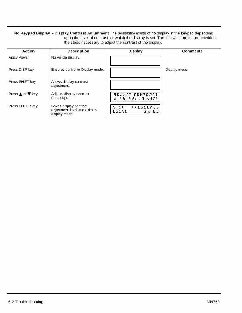
5-2 Troubleshooting MN750
No Keypad Display - Display Contrast Adjustment The possibility exists of no display in the keypad dependingupon the level of contrast for which the display is set. The following procedure providesthe steps necessary to adjust the contrast of the display.
Action Description Display Comments
Apply Power No visible display.
Press DISP key Ensures control in Display mode. Display mode.
Press SHIFT key Allows display contrastadjustment.
Press � or � key Adjusts display contrast(intensity).
Press ENTER key Saves display contrastadjustment level and exits todisplay mode.

Troubleshooting 5-3MN750
How to Access Display Screens and Diagnostic Information
Action Description Display Comments
Apply Power Logo display for 5 seconds.
Display mode showing outputfrequency.
Display mode. If in REMOTE,press DISP for this display.
Press DISP key Display mode showing arepresentation of motor speedbased on output frequency.
Press DISP key Display mode showing outputcurrent.
Press DISP key Display mode showing outputvoltage.
Press DISP key Display mode showingcombination of output current,voltage, frequency and motorRPM.
Press DISP key Fault log entry point. Press DISPto continue to next display screen.
Press ENTER to access fault logrecord.
Press DISP key Diagnostic information entry point.Press DISP to continue to nextdisplay screen.
Press ENTER to accessdiagnostic information.
Press DISP key Display modified parametersentry point. Press DISP tocontinue to next display screen.
Press ENTER to displayparameters that have beenchanged from factory settings.
Press DISP key Local keypad enter for speedentry point. Press DISP tocontinue to next display screen.
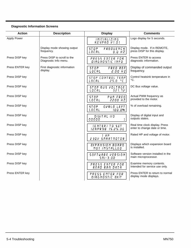
5-4 Troubleshooting MN750
Diagnostic Information Screens
Action Description Display Comments
Apply Power Logo display for 5 seconds.
Display mode showing outputfrequency.
Display mode. If in REMOTE,press DISP for this display.
Press DISP key Press DISP to scroll to theDIagnostic Info menu.
Press ENTER to accessdiagnostic information.
Press ENTER key First diagnostic informationdisplay.
Display of commanded outputfrequency.
Press DISP key Control heatsink temperature in°C.
Press DISP key DC Bus voltage value.
Press DISP key Actual PWM frequency asprovided to the motor.
Press DISP key % of overload remaining.
Press DISP key Display of digital input andoutputs states.
Press DISP key Real time clock display. Pressenter to change date or time.
Press DISP key Rated HP and voltage of motor.
Press DISP key Displays which expansion boardis installed.
Press DISP key Software version installed in themain microprocessor.
Press DISP key Examine memory contents.Intended for service use only.
Press ENTER key Press ENTER to return to normaldisplay mode displays.

Troubleshooting 5-5MN750
How to Set Date and Time
To change date and time, access the DIagnostic Info display as previously described in“Diagnostic Information Screens”.
Action Description Display Comments
Diagnostic information entry point. Press ENTER to accessdiagnostic information.
Press ENTER key First diagnostic info display.Scroll to date and time display.
Press ENTER to displayparameters that have beenchanged from factory settings.
Press DISP key Scroll to date and timeinformation.
Press ENTER key Access date and time information.
Press � or � key Change date. Press SHIFT whenfinished to change month.
Press � or � key Change month. Press SHIFTwhen finished to change year.
Press � or � key Change year. Press SHIFT whenfinished to change hours.
Press � or � key Change hours. Press SHIFTwhen finished to change minutes.
Press � or � key Change minutes. Press SHIFTwhen finished to change seconds.
Press � or � key Change seconds. Press ENTERwhen finished.
Press ENTER when finished tosave date and time and exit thislevel.
Press ENTER key Press ENTER to save the clocksettings and exit clock settingmode.
Press DISP key Scroll to Diagnostic Exit.
Press ENTER key Display mode showing outputfrequency.
DIsplay mode.

5-6 Troubleshooting MN750
How to Access the Fault Log
When a fault condition occurs, motor operation stops and a fault code is displayed on theKeypad display. The control keeps a log of the last 31 faults. To access the fault logperform the following procedure:
Action Description Display Comments
Apply Power Logo display for 5 seconds.
Display mode showing outputfrequency.
Display mode.
Press DISP key Press DISP to scroll to the FaultLog entry point.
Press ENTER key Displays most recent message.
Press � or � key Scroll through fault messages. If no messages, the exit messageis displayed.
Press ENTER key Return to display mode.
How to Clear the Fault Log Use the following procedure to clear the fault log.
Action Description Display Comments
Apply Power Logo display for 5 seconds.
Display mode showing outputfrequency.
Display mode.
Press DISP key Press DISP to scroll to the FaultLog entry point.
Press ENTER key Displays most recent message.
Press SHIFT key
Press RESET key
Press SHIFT key
Press ENTER key Fault log is cleared. No faults in fault log.
Press � or � key Scroll to Fault Log Exit.
Press ENTER key Return to display mode.
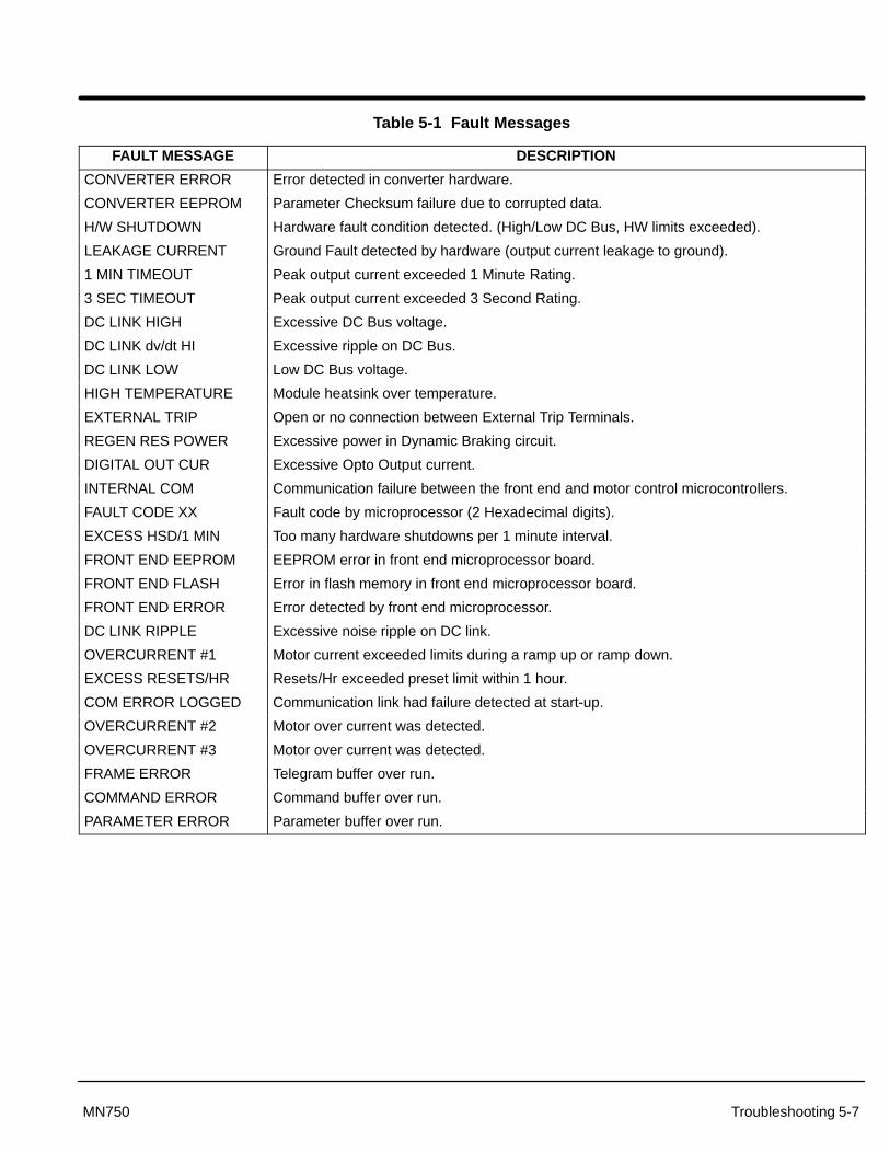
Troubleshooting 5-7MN750
Table 5-1 Fault Messages
FAULT MESSAGE DESCRIPTION
CONVERTER ERROR Error detected in converter hardware.
CONVERTER EEPROM Parameter Checksum failure due to corrupted data.
H/W SHUTDOWN Hardware fault condition detected. (High/Low DC Bus, HW limits exceeded).
LEAKAGE CURRENT Ground Fault detected by hardware (output current leakage to ground).
1 MIN TIMEOUT Peak output current exceeded 1 Minute Rating.
3 SEC TIMEOUT Peak output current exceeded 3 Second Rating.
DC LINK HIGH Excessive DC Bus voltage.
DC LINK dv/dt HI Excessive ripple on DC Bus.
DC LINK LOW Low DC Bus voltage.
HIGH TEMPERATURE Module heatsink over temperature.
EXTERNAL TRIP Open or no connection between External Trip Terminals.
REGEN RES POWER Excessive power in Dynamic Braking circuit.
DIGITAL OUT CUR Excessive Opto Output current.
INTERNAL COM Communication failure between the front end and motor control microcontrollers.
FAULT CODE XX Fault code by microprocessor (2 Hexadecimal digits).
EXCESS HSD/1 MIN Too many hardware shutdowns per 1 minute interval.
FRONT END EEPROM EEPROM error in front end microprocessor board.
FRONT END FLASH Error in flash memory in front end microprocessor board.
FRONT END ERROR Error detected by front end microprocessor.
DC LINK RIPPLE Excessive noise ripple on DC link.
OVERCURRENT #1 Motor current exceeded limits during a ramp up or ramp down.
EXCESS RESETS/HR Resets/Hr exceeded preset limit within 1 hour.
COM ERROR LOGGED Communication link had failure detected at start-up.
OVERCURRENT #2 Motor over current was detected.
OVERCURRENT #3 Motor over current was detected.
FRAME ERROR Telegram buffer over run.
COMMAND ERROR Command buffer over run.
PARAMETER ERROR Parameter buffer over run.
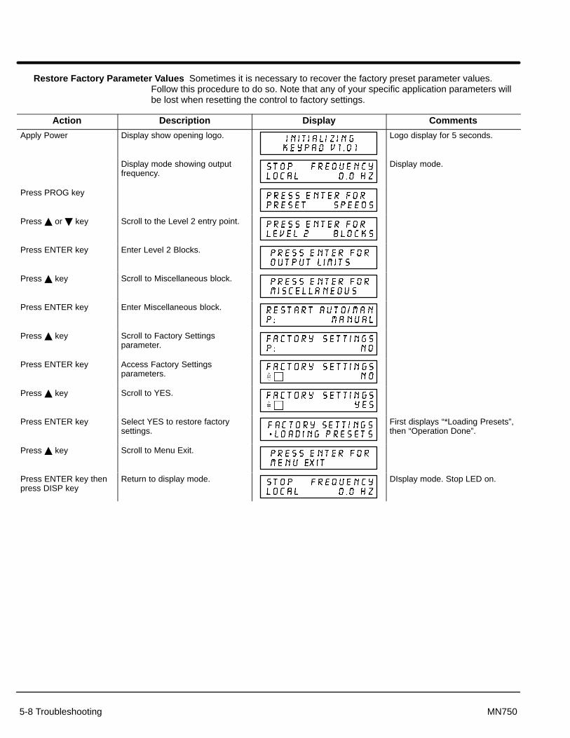
5-8 Troubleshooting MN750
Restore Factory Parameter V alues Sometimes it is necessary to recover the factory preset parameter values.Follow this procedure to do so. Note that any of your specific application parameters willbe lost when resetting the control to factory settings.
Action Description Display Comments
Apply Power Display show opening logo. Logo display for 5 seconds.
Display mode showing outputfrequency.
Display mode.
Press PROG key
Press � or � key Scroll to the Level 2 entry point.
Press ENTER key Enter Level 2 Blocks.
Press � key Scroll to Miscellaneous block.
Press ENTER key Enter Miscellaneous block.
Press � key Scroll to Factory Settingsparameter.
Press ENTER key Access Factory Settingsparameters.
Press � key Scroll to YES.
Press ENTER key Select YES to restore factorysettings.
First displays “*Loading Presets”,then “Operation Done”.
Press � key Scroll to Menu Exit.
Press ENTER key thenpress DISP key
Return to display mode. DIsplay mode. Stop LED on.

Troubleshooting 5-9MN750
Table 5-2 Troubleshooting
INDICATION POSSIBLE CAUSE CORRECTIVE ACTION
Wrong Date & Time Improper setting. Set Date and time in Diagnostic Info area.
Low internal battery. Contact service.
No Display Lack of input voltage. Check input power for proper voltage.
Loose connections. Check input power termination.Verify connection of operator keypad.
Incorrect contrast setting. Adjust display contrast. See Adjust Display Contrast in Sec. 4.
Motor Will Not Start Not enough starting torque. Increase first the torque boost setting, then dynamic boost if necessary.
Motor overloaded. Check for proper motor loading.Check couplings for binding.Order correct size SmartMotor.
Control not in local mode (Keypad)or remote mode (for terminal strip).
Place control in local mode for Keypad operation.Place control in remote mode for terminal strip operation.
Motor may be commanded to runbelow minimum frequency setting.
Increase speed command or lower minimum frequency setting.
Motor Will NotReach MaximumSpeed
Maximum frequency limit set toolow.
Adjust maximum output frequency setting.
SpeedMotor overloaded. Check for mechanical overload. If unloaded motor shaft does not rotate
freely, check motor bearings.
Improper speed command. Verify control is receiving proper command signal at input terminals.Verify control is set to receive your speed command.
Speed potentiometer. Replace potentiometer.
Motor Will Not StopRotation
Minimum frequency limit set toohigh
Adjust minimum output frequency.
Improper speed command. Verify control is receiving proper command signal at input terminals.Verify control is set to receive your speed command.
Speed potentiometer failure. Replace potentiometer.
Unstable Speed(Motor Unloaded)
Unloaded motors can oscillate attheir natural frequency.
Change the V/Hz Profile to 100% square law while motor shaft isunloaded. When a load is connected, use the Linear V/Hz profile.
Unstable Speed(Motor Loaded)
Oscillating load connected to motor. Correct motor loading.(Motor Loaded)
Unstable input power. Correct input power.
Slip compensation set too high. Adjust slip compensation.
Motor Runs RoughAt Low Speeds(Motor Unloaded)
Unloaded motors can oscillate attheir natural frequency.
Change the V/Hz Profile to 100% square law while motor shaft isunloaded. When a load is connected, use the Linear V/Hz profile.
Motor Runs RoughAt Low Speeds
Torque boost set too high. Adjust torque boost setting.At Low Speeds(Motor Loaded) Misalignment of motor/load
coupling.Check coupling alignment.
Faulty motor. Check motor winding connections.

5-10 Troubleshooting MN750
Table 5-2 Troubleshooting Continued
INDICATION POSSIBLE CAUSE CORRECTIVE ACTION
HW Shutdown (during Ramp upor down)
Decel times are too short. Inertia istoo big for the decel time. Foldbackprotection is off.
Increase the decel time. If this is not possible, install dynamic brake kit. Setting Level 2 Protection block, Foldback to ON will extend the decel timeto help prevent the HW shutdown fault. Depending on the inertia, thedecel time may still have to increased.
HW Shutdown Fault condition detected. Reset SmartMotor.
Noise entering control logic circuits. Check for proper grounding of power wiring.Verify proper shielding of signal wiring.
Motor overloaded. Verify sizing of SmartMotor.Correct motor loading.
Incorrect DC bus voltage. Reset control. If error still exists, go to diagnostic screens and check thatthe bus voltage is within ± 5VDC of rating (230VAC=325VDC bus,460VAC=650VDC bus).
Input voltage too high. Check input voltage.Use transformer to step down voltage.Use line reactor to minimize voltage spikes.
Decel rate set too quickly. Increase decel time.Add external dynamic braking module.
Overhauling motor load. Correct motor load.Add external dynamic braking module.
HW Shutdown or DC Link Low
Insufficient input voltage. Verify proper input voltage.Use a transformer to step up voltage.Check power line disturbances due to starting other equipment.Monitor power line for correlation of time/date and power fluctuations.Contact power company.
DC Link High Incorrect DC bus voltage. In diagnostic screens check that the bus voltage is within ± 5VDC of rating(230VAC=325VDC bus, 460VAC=650VDC bus). Contact Baldor service.
DC Link Low Low input voltage or excessiveripple on input power lines.
Reset control. If error still exists, go to diagnostic screens and check thatthe bus voltage is within ± 5VDC of rating (230VAC=325VDC bus,460VAC=650VDC bus). Contact Baldor service.
DC Link dv/dtHigh
Excessive ripple on input powerlines. Single phase input powermay be insufficient for application.
Reset control. If error still exists, go to diagnostic screens and check thatthe bus voltage is within ± 5VDC of rating (230VAC=325VDC bus,460VAC=650VDC bus). Contact Baldor service.
High Temperature Motor overloaded. Correct motor loading.Order correct size SmartMotor.
Ambient temperature too high. Reduce ambient temperature.Add cooling fans or air conditioning.
PWM vs TEMP is set to off. Set Level 2 Protection block, PWM vs TEMP to ON. When thetemperature exceeds a predetermined limit, the PWM frequency will bedecreased automatically.
Motor fan is ineffective. Clean debris from fan and heatsink fins.Replace fan blade if necessary.
Front EndEEPROM
Failure to read or write to memory. Reset control.Reset control parameters to factory settings.Control unit failure, contact service.
ConverterEEPROM
Parameter checksum failure due tocorrupt data.
Reset control.Reset control parameters to factory settings.Control unit failure, contact service.
Fault Code XX Fault detected by mainmicroprocessor. 2 digit Hex value isalso displayed.
Reset control.Reset control parameters to factory settings.Control unit failure, contact service.
Leakage Current Output current leakage to ground. Check motor leads and connections for grounds.Verify motor is not internally grounded.

Troubleshooting 5-11MN750
Table 5-2 Troubleshooting Continued
1 Min Timeout Peak output current exceeded 1minute rating.
Increase PK current limit parameter setting.Check motor for overloading.Check that the Torque Boost parameter value is not set too high.Order correct size SmartMotor.
3 Sec Timeout Peak output current exceeded 3second rating.
Increase PK current limit parameter setting.Check motor for overloading.Check the ACCEL time and increase if necessary.Check that the Torque Boost parameter value is not set too high.Order correct size SmartMotor.
Regen ResPower
Excessive power in dynamic brakecircuit.
Verify proper Ohm and Watt parameters.Increase decel time.Add/increase external dynamic braking capability.
Digital OUT CUR Digital output is overloaded. Be sure OPTO output current is less than 60 mA. Check relay protection diode for correct position.
Internal Com Communication failure between thefront end and motor controlmicrocontrollers.
The green LED should blink consistently. An erratic blinking pattern mightindicate noise in the communication hardware. Check input power and allwires connected to the smart motor.
Excess HSD/1min
Too many H/W Shutdowns within 1 minute.
Check if attempting to autorestart into a load. Increase delay time ofautorestart. Check load. See other H/W shutdown corrective actions.
Front End Flash Error in flash memory on front endboard.
Reset control.Reset control parameters to factory settings.Control unit failure, contact service.
Front End Error Memory access error in front endprocessor.
Reset control.Reset control parameters to factory settings.Control unit failure, contact service.
DC link Ripple Excessive ripple on DC bus. Inputpower has noise on the lines.
Reset control. If error still exists, go to diagnostic screens and check thatthe bus voltage is within ± 5VDC of rating (230VAC=325VDC bus,460VAC=650VDC bus). Contact Baldor service.
Overcurrent #1 Over current was detected. If occurred during ramping motor at start up, check load. Check boost setting, V/HZ profile.
Overcurrent #2 Over current was detected.Check boost setting, V/HZ rofile. Increase accel time. Increase or decrease torque boost.
Overcurrent #3 Over current was detected.Increase or decrease torque boost. Change V/HZ profile to a square law setting, or try 9 points. Motor may be shorted. Contact Baldor service.
Converter Error Hardware detected by powermodule.
Reset fault. Reset power. Contact Baldor service.
ExcessResets/HR
Too many attempted auto restarts in1 hour.
Clear fault log. Be sure no more than maximum number of restarts occurper hour as set by RESTART FAULT/HR parameter. This should onlyoccur if you are doing auto restarts. Set RESTART AUTO/MAN toMANUAL if not needed.
Com Error logged Communication failure between thefront end and motor controlmicrocontrollers.
This error occurs after a communication error has occurred and may stopthe motor. Check the fault log for more errors, possibly Internal com. The green LED should blink consistently. An erratic blinking pattern mightindicate noise in the communication hardware. Check input power and allwires connected to the smart motor.
Frame error Internal buffer overrun error. Reset control.Reset control parameters to factory settings.Control unit failure, contact service.
Command error Command buffer overrun error. Commands received from a remote serial terminal are spaced too closely.Commands must be spaced at least 75ms apart.
Parameter error Parameter buffer overrun error. If this occurred while being commanded by the remote terminal, check thatthe input reference is not corrupted by noise. Check if frequency referencein diagnostic menu is changing according to your input signal.
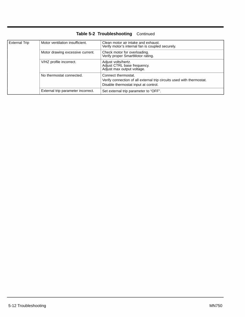
5-12 Troubleshooting MN750
Table 5-2 Troubleshooting Continued
External Trip Motor ventilation insufficient. Clean motor air intake and exhaust.Verify motor’s internal fan is coupled securely.
Motor drawing excessive current. Check motor for overloading.Verify proper SmartMotor rating.
V/HZ profile incorrect. Adjust volts/hertz.Adjust CTRL base frequency.Adjust max output voltage.
No thermostat connected. Connect thermostat.Verify connection of all external trip circuits used with thermostat.Disable thermostat input at control.
External trip parameter incorrect. Set external trip parameter to “OFF”.

Section 6Specifications & Product Data
Specifications & Product Data 6-1MN750
Specifications:
Horsepower 1 to 10 HP @ 230VAC1 to 10 HP @ 460VAC
Input Frequency 50/60 HZ ± 5%
Service Factor 1.0
Duty Continuous
Overload Capacity Constant Torque Rating: 200% for 3 secs150% for 60 secs
Variable Torque Rating: 115% for 60 secs
Storage Temperature -30 °C to +65 °C
Control Method Sinewave Carrier Input, PWM Output
Frequency Accuracy 0.125 Hz @ 60Hz
Frequency Resolution 0.1 Hz Digital (0.05 % Analog)
Carrier Frequency 2.2kHz to 18kHz Adjustable
Transistor Type Fast Switching Transistor
Transistor Rise Time 2500V/�sec. (dv/dt)
Torque Boost Automatic adjustment to load (Standard)0 to 15% of Input Voltage (Manual)
Volts/Hertz Pattern Linear, Squared Reduced, Nine Point
Accel/Decel Time 0 to 3600 sec. for 2 Assignable Plus JOG
S-Curves 0 to 100%
Base Frequency 10 to 120Hz
Regenerative Braking Torque 20% minimum
JOG Frequency 0 to 120Hz
Skip Frequency 0 to 120Hz
Minimum Output Frequency 0 to 120Hz
Maximum Output Frequency 0 to maximum Frequency
Auto Restart Manual or Automatic
Slip Compensation 0 to 6 Hz
Opto Isolated Input Impedance 6.8 k� (Closed Contacts Standard)
Opto Isolated Input Leakage Current 10�A maximum
Operating Modes KEYPAD, #1, 2 Wire/7Speed, #2, 2 Wire/Trip, #3, 2 Wire/3 Speed, #4, 3 Wire/3 Speed, #5, 3 Wire/Trip, #6, 2 Wire/Electronic Potentiometer, #7, 3 Wire/Electronic PotentiometerPROF RUN-REMPROF RUN-LOC
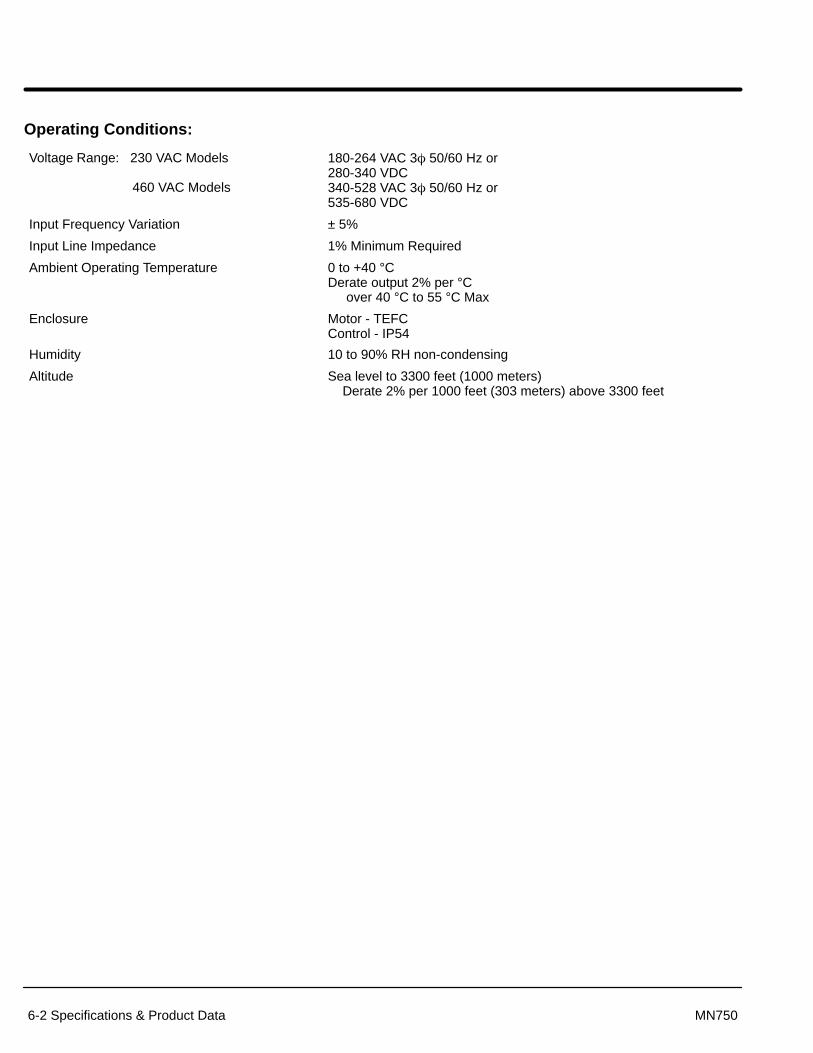
6-2 Specifications & Product Data MN750
Operating Conditions:
Voltage Range: 230 VAC Models
460 VAC Models
180-264 VAC 3� 50/60 Hz or280-340 VDC340-528 VAC 3� 50/60 Hz or535-680 VDC
Input Frequency Variation ± 5%
Input Line Impedance 1% Minimum Required
Ambient Operating Temperature 0 to +40 °CDerate output 2% per °C over 40 °C to 55 °C Max
Enclosure Motor - TEFCControl - IP54
Humidity 10 to 90% RH non-condensing
Altitude Sea level to 3300 feet (1000 meters) Derate 2% per 1000 feet (303 meters) above 3300 feet

Specifications & Product Data 6-3MN750
Optional Keypad Display:
Display Backlit LCD alphanumeric 2 Lines x 16 characters
Keys 12 key Membrane with tactile response
Functions Output status monitoringDigital speed controlParameter setting and displayFault log displayMotor run and jogLocal/Remote toggle
LED Indicators Forward run commandReverse run commandStop commandJog active
Connector Type RJ-12 Series (6 conductor phone jack)
Remote Mount 100 feet max from control
Analog Input:
Full Scale Range 0 - 5 VDC, 0 - 10 VDC, 0 - 20 mA, 4 - 20 mA
Resolution 8 bits
Input Impedance 20k�
Analog Output:
Full Scale Range 0-10 VDC, 0-5 VDC
Source Current 1 mA maximum
Resolution 8 bits
Conditions Frequency, Freq Command, AC Current, AC Voltage, Bus Voltage, Zero Calibration and 100% Calibration
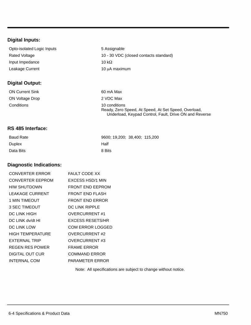
6-4 Specifications & Product Data MN750
Digital Inputs:
Opto-isolated Logic Inputs 5 Assignable
Rated Voltage 10 - 30 VDC (closed contacts standard)
Input Impedance 10 k�
Leakage Current 10 �A maximum
Digital Output:
ON Current Sink 60 mA Max
ON Voltage Drop 2 VDC Max
Conditions 10 conditionsReady, Zero Speed, At Speed, At Set Speed, Overload, Underload, Keypad Control, Fault, Drive ON and Reverse
RS 485 Interface:
Baud Rate 9600; 19,200; 38,400; 115,200
Duplex Half
Data Bits 8 Bits
Diagnostic Indications:
CONVERTER ERROR FAULT CODE XX
CONVERTER EEPROM EXCESS HSD/1 MIN
H/W SHUTDOWN FRONT END EEPROM
LEAKAGE CURRENT FRONT END FLASH
1 MIN TIMEOUT FRONT END ERROR
3 SEC TIMEOUT DC LINK RIPPLE
DC LINK HIGH OVERCURRENT #1
DC LINK dv/dt HI EXCESS RESETS/HR
DC LINK LOW COM ERROR LOGGED
HIGH TEMPERATURE OVERCURRENT #2
EXTERNAL TRIP OVERCURRENT #3
REGEN RES POWER FRAME ERROR
DIGITAL OUT CUR COMMAND ERROR
INTERNAL COM PARAMETER ERROR
Note: All specifications are subject to change without notice.

Specifications & Product Data 6-5MN750
Ratings – SmartMotor Constant T orque – NEMA 1 Control Enclosure
CatalogNumber
HP @Base
Speed
BaseSpeed
@ 60Hz
NEMAFrame
Constant TorqueSpeed Range
MaxOutputSpeed
InputCurrent(Amps)
RatedPWMFreq
BaldorType
Approx.ShippingWeightSpeed @ 60Hz
Min RPM Max RPMSpeed (Amps ) Freq.
(kHz)Weight
230 Volt Input
CSM3546T - 2 1 1750 143TC 180 1800 3500 3.1 18.0 DV3524M 48
CSM3558T - 2 2 1750 145TC 180 1800 3500 5.7 18.0 DV3540M 59
CSM3611T - 2 3 1760 182TC 180 1800 3520 10.5 18.0 DV3628M 76
CSM3615T - 2 5 1760 184TC 180 1800 3520 15.9 9.0 DV3646M 93
CSM3710T - 2 7.5 1725 213TC 180 1800 3450 22.8 9.0 DV3734M 130
CSM3714T - 2 10 1725 215TC 180 1800 3450 29.3 9.0 DV3746M 158
460 Volt Input
CSM3546T - 4 1 1750 143TC 180 1800 3500 1.6 18.0 DV3524M 48
CSM3558T - 4 2 1750 145TC 180 1800 3500 2.9 18.0 DV3540M 59
CSM3611T - 4 3 1760 182TC 180 1800 3520 5.4 18.0 DV3628M 74
CSM3615T - 4 5 1760 184TC 180 1800 3520 7.8 9.0 DV3646M 91
CSM3710T - 4 7.5 1725 213TC 180 1800 3450 11.4 9.0 DV3734M 127
CSM3714T - 4 10 1725 215TC 180 1800 3450 14.7 9.0 DV3746M 155
Ratings – SmartMotor Constant T orque – NEMA 4 Control Enclosure
CatalogNumber
HP @Base
Speed
BaseSpeed
@ 60Hz
NEMAFrame
Constant TorqueSpeed Range
MaxOutputSpeed
InputCurrent(Amps)
RatedPWMFreq
BaldorType
Approx.ShippingWeightSpeed @ 60Hz
Min RPM Max RPMSpeed (Amps ) Freq.
(kHz)Weight
230 Volt Input
CWDSM3546T - 2 1 1750 143TC 180 1800 3500 3.1 18.0 DV3524M 48
CWDSM3558T - 2 2 1750 145TC 180 1800 3500 5.7 18.0 DV3540M 59
CWDSM3611T - 2 3 1760 182TC 180 1800 3520 10.5 18.0 DV3628M 76
CWDSM3615T - 2 5 1760 184TC 180 1800 3520 15.9 9.0 DV3646M 93
CWDSM3710T - 2 7.5 1725 213TC 180 1800 3450 22.8 9.0 DV3734M 130
CWDSM3714T - 2 10 1725 215TC 180 1800 3450 29.3 9.0 DV3746M 158
460 Volt Input
CWDSM3546T - 4 1 1750 143TC 180 1800 3500 1.6 18.0 DV3524M 48
CWDSM3558T - 4 2 1750 145TC 180 1800 3500 2.9 18.0 DV3540M 59
CWDSM3611T - 4 3 1760 182TC 180 1800 3520 5.4 18.0 DV3628M 74
CWDSM3615T - 4 5 1760 184TC 180 1800 3520 7.8 9.0 DV3646M 91
CWDSM3710T - 4 7.5 1725 213TC 180 1800 3450 11.4 9.0 DV3734M 127
CWDSM3714T - 4 10 1725 215TC 180 1800 3450 14.7 9.0 DV3746M 155

6-6 Specifications & Product Data MN750
Terminal Tightening Torque Specifications – NEMA 1 Control Enclosure
CatalogNumber
HP@ Base
Base Speed@ 60Hz
NEMA Frame Power Terminal TB1 Casting GroundNumber @ Base
Speed@ 60Hz
Lb-In Nm Lb-In Nm
230 Volt Input
CSM3546T- 2 1 1750 143TC 11-13 1.2-1.5 50-60 5.6-6.8
CSM3558T - 2 2 1750 145TC 11-13 1.2-1.5 50-60 5.6-6.8
CSM3611T - 2 3 1760 182TC 11-13 1.2-1.5 50-60 5.6-6.8
CSM3615T - 2 5 1760 184TC 11-13 1.2-1.5 50-60 5.6-6.8
CSM3710T - 2 7.5 1725 213TC 11-13 1.2-1.5 50-60 5.6-6.8
CSM3714T - 2 10 1725 215TC 11-13 1.2-1.5 50-60 5.6-6.8
460 Volt Input
CSM3546T- 4 1 1750 143TC 11-13 1.2-1.5 50-60 5.6-6.8
CSM3558T - 4 2 1750 145TC 11-13 1.2-1.5 50-60 5.6-6.8
CSM3611T - 4 3 1760 182TC 11-13 1.2-1.5 50-60 5.6-6.8
CSM3615T - 4 5 1760 184TC 11-13 1.2-1.5 50-60 5.6-6.8
CSM3710T - 4 7.5 1725 213TC 11-13 1.2-1.5 50-60 5.6-6.8
CSM3714T - 4 10 1725 215TC 11-13 1.2-1.5 50-60 5.6-6.8
Terminal Tightening Torque Specifications – NEMA 4 Control Enclosure
CatalogNumber
HP@ Base
Base Speed@ 60Hz
NEMA Frame Power Terminal TB1 Casting GroundNumber @ Base
Speed@ 60Hz
Lb-In Nm Lb-In Nm
230 Volt Input
CWDSM3546T- 2 1 1750 143TC 11-13 1.2-1.5 50-60 5.6-6.8
CWDSM3558T - 2 2 1750 145TC 11-13 1.2-1.5 50-60 5.6-6.8
CWDSM3611T - 2 3 1760 182TC 11-13 1.2-1.5 50-60 5.6-6.8
CWDSM3615T - 2 5 1760 184TC 11-13 1.2-1.5 50-60 5.6-6.8
CWDSM3710T - 2 7.5 1725 213TC 11-13 1.2-1.5 50-60 5.6-6.8
CWDSM3714T - 2 10 1725 215TC 11-13 1.2-1.5 50-60 5.6-6.8
460 Volt Input
CWDSM3546T- 4 1 1750 143TC 11-13 1.2-1.5 50-60 5.6-6.8
CWDSM3558T - 4 2 1750 145TC 11-13 1.2-1.5 50-60 5.6-6.8
CWDSM3611T - 4 3 1760 182TC 11-13 1.2-1.5 50-60 5.6-6.8
CWDSM3615T - 4 5 1760 184TC 11-13 1.2-1.5 50-60 5.6-6.8
CWDSM3710T - 4 7.5 1725 213TC 11-13 1.2-1.5 50-60 5.6-6.8
CWDSM3714T - 4 10 1725 215TC 11-13 1.2-1.5 50-60 5.6-6.8

Specifications & Product Data 6-7MN750
Baldor SmartMotor 35 Frame
13.308 to 15.56 *
6 HOLES.34 DIA.
5.94
4.00
5.00
8.73
.8750
.8745
2.75
.50
6.50
4.5004.497
2.12
.13
.13 .19 KEY1.38 LONG
10.27
45°
2.75 2.75
.38–16 TAPON 5.88 DIA
4 HOLES45°
6.03
7.20
3.50
3.25
6.50
+.00–.06
Air Flow
* Call your local Baldor District Office for dimension information.

6-8 Specifications & Product Data MN750
Baldor SmartMotor 36 Frame
Air Flow
* Call your local Baldor District Office for dimension information.
15.18 to 18.05 *

Specifications & Product Data 6-9MN750
Baldor SmartMotor 37 Frame
Air Flow
* Call your local Baldor District Office for dimension information.
18.647

6-10 Specifications & Product Data MN750
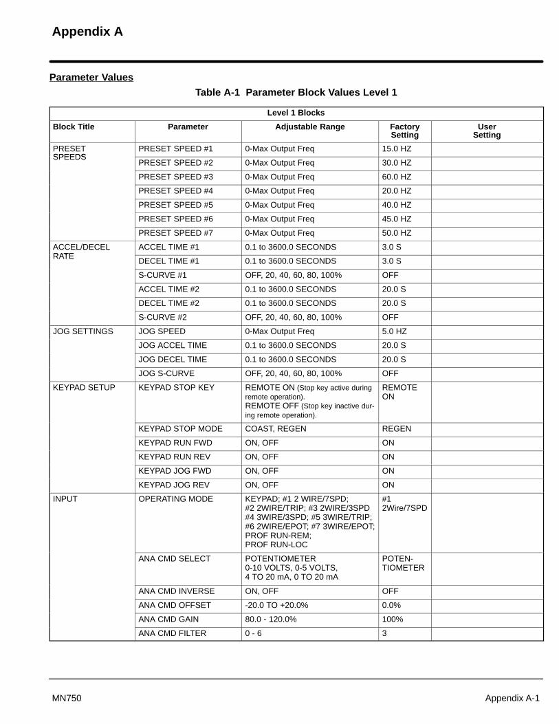
Appendix A
Appendix A-1MN750
Parameter Values
Table A-1 Parameter Block Values Level 1
Level 1 Blocks
Block Title Parameter Adjustable Range FactorySetting
UserSetting
PRESETSPEEDS
PRESET SPEED #1 0-Max Output Freq 15.0 HZSPEEDS
PRESET SPEED #2 0-Max Output Freq 30.0 HZ
PRESET SPEED #3 0-Max Output Freq 60.0 HZ
PRESET SPEED #4 0-Max Output Freq 20.0 HZ
PRESET SPEED #5 0-Max Output Freq 40.0 HZ
PRESET SPEED #6 0-Max Output Freq 45.0 HZ
PRESET SPEED #7 0-Max Output Freq 50.0 HZ
ACCEL/DECELRATE
ACCEL TIME #1 0.1 to 3600.0 SECONDS 3.0 SRATE
DECEL TIME #1 0.1 to 3600.0 SECONDS 3.0 S
S-CURVE #1 OFF, 20, 40, 60, 80, 100% OFF
ACCEL TIME #2 0.1 to 3600.0 SECONDS 20.0 S
DECEL TIME #2 0.1 to 3600.0 SECONDS 20.0 S
S-CURVE #2 OFF, 20, 40, 60, 80, 100% OFF
JOG SETTINGS JOG SPEED 0-Max Output Freq 5.0 HZ
JOG ACCEL TIME 0.1 to 3600.0 SECONDS 20.0 S
JOG DECEL TIME 0.1 to 3600.0 SECONDS 20.0 S
JOG S-CURVE OFF, 20, 40, 60, 80, 100% OFF
KEYPAD SETUP KEYPAD STOP KEY REMOTE ON (Stop key active duringremote operation).REMOTE OFF (Stop key inactive dur-ing remote operation).
REMOTEON
KEYPAD STOP MODE COAST, REGEN REGEN
KEYPAD RUN FWD ON, OFF ON
KEYPAD RUN REV ON, OFF ON
KEYPAD JOG FWD ON, OFF ON
KEYPAD JOG REV ON, OFF ON
INPUT OPERATING MODE KEYPAD; #1 2 WIRE/7SPD;#2 2WIRE/TRIP; #3 2WIRE/3SPD #4 3WIRE/3SPD; #5 3WIRE/TRIP; #6 2WIRE/EPOT; #7 3WIRE/EPOT;PROF RUN-REM; PROF RUN-LOC
#12Wire/7SPD
ANA CMD SELECT POTENTIOMETER 0-10 VOLTS, 0-5 VOLTS, 4 TO 20 mA, 0 TO 20 mA
POTEN-TIOMETER
ANA CMD INVERSE ON, OFF OFF
ANA CMD OFFSET -20.0 TO +20.0% 0.0%
ANA CMD GAIN 80.0 - 120.0% 100%
ANA CMD FILTER 0 - 6 3

A-2 Appendix MN750
Table A-1 Parameter Block Values Level 1 Continued
Level 1 Blocks - Continued
Block Title Parameter Adjustable Range FactorySetting
UserSetting
OUTPUT OPTO OUTPUT #1 READY, ZERO SPEED, AT SPEED, AT SET SPEED,OVERLOAD, UNDERLOAD,KEYPAD CONTROL, FAULT,DRIVE ON, REVERSE
READY
ZERO SPD SET PT 0-Max Output Freq 6.0 HZ
AT SPEED BAND 0-20.0 HZ 13.6 HZ
SET SPEED POINT 0-Max Output Freq 60.0 HZ
OVERLOAD SET PT 0.2 to Peak Rated Current Peak RatedCurrent
UNDERLOAD SET PT 0.2 to Peak Rated Current 0.2A
ANA VOLT RANGE 0-10, 0-5 VOLTS 0-10 VOLTS
ANALOG OUT #1 FREQUENCY, FREQ COMMAND,AC CURRENT, AC VOLTAGE, BUS VOLTAGE, ZERO CAL, 100% CAL.
FREQUENCY
ANALOG SCALE #1 10 - 160% 100%
V/HZ AND BOOST CTRL BASE FREQ 10 - 120 HZ 60 HZ
TORQUE BOOST 0 - 15% Factory Set
DYNAMIC BOOST 0.0 - 100.0% 0%
SLIP COMP ADJ 0.00 - 6.00 HZ 0.0 HZ
V/HZ PROFILE LINEAR, 33% SQUARE LAW, 67% SQUARE LAW, 100% SQUARE LAW9 POINTS
LINEAR
MAX OUTPUT VOLTS 0 - 100% 100%
LEVEL 2 BLOCK ENTERS LEVEL 2 MENU - See Table A-2.
�����������
���������� ��
Exit programming mode and return to display mode.
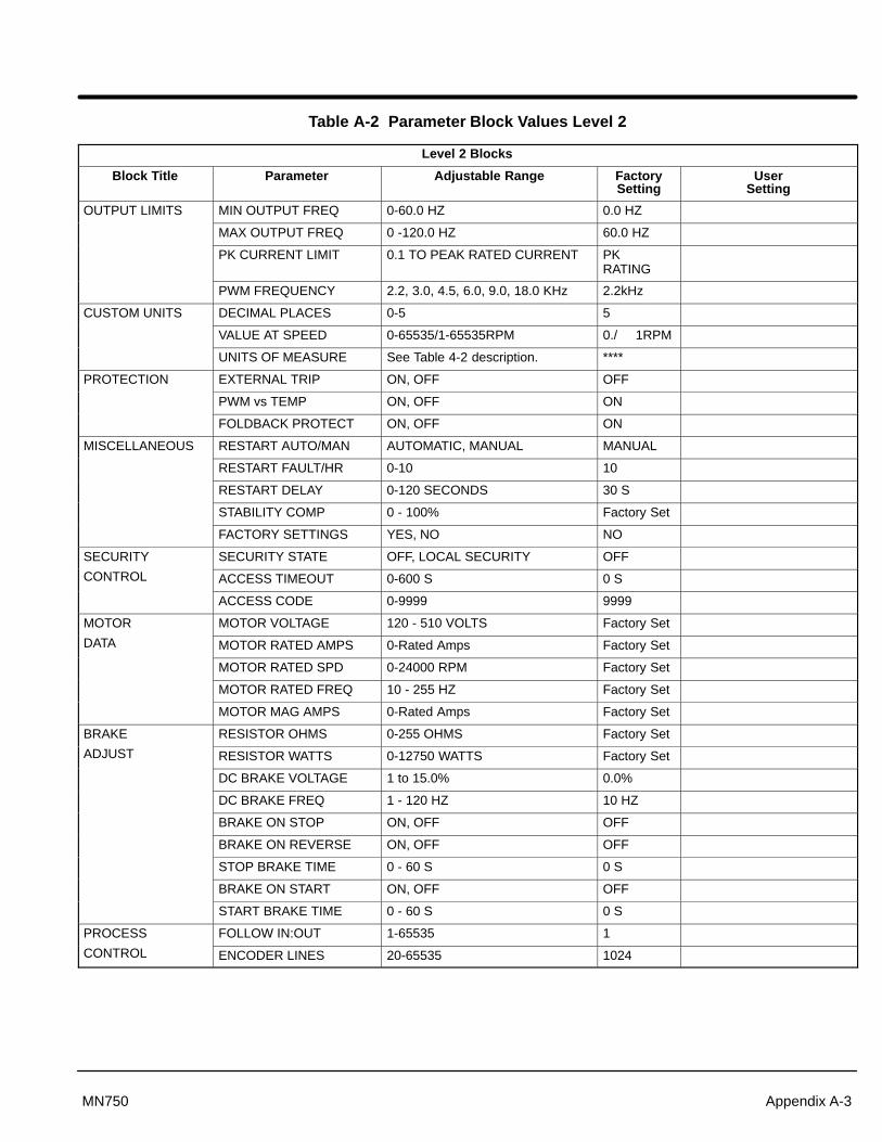
Appendix A-3MN750
Table A-2 Parameter Block Values Level 2
Level 2 Blocks
Block Title Parameter Adjustable Range FactorySetting
UserSetting
OUTPUT LIMITS MIN OUTPUT FREQ 0-60.0 HZ 0.0 HZ
MAX OUTPUT FREQ 0 -120.0 HZ 60.0 HZ
PK CURRENT LIMIT 0.1 TO PEAK RATED CURRENT PK RATING
PWM FREQUENCY 2.2, 3.0, 4.5, 6.0, 9.0, 18.0 KHz 2.2kHz
CUSTOM UNITS DECIMAL PLACES 0-5 5
VALUE AT SPEED 0-65535/1-65535RPM 0./ 1RPM
UNITS OF MEASURE See Table 4-2 description. ****
PROTECTION EXTERNAL TRIP ON, OFF OFF
PWM vs TEMP ON, OFF ON
FOLDBACK PROTECT ON, OFF ON
MISCELLANEOUS RESTART AUTO/MAN AUTOMATIC, MANUAL MANUAL
RESTART FAULT/HR 0-10 10
RESTART DELAY 0-120 SECONDS 30 S
STABILITY COMP 0 - 100% Factory Set
FACTORY SETTINGS YES, NO NO
SECURITY SECURITY STATE OFF, LOCAL SECURITY OFF
CONTROL ACCESS TIMEOUT 0-600 S 0 S
ACCESS CODE 0-9999 9999
MOTOR MOTOR VOLTAGE 120 - 510 VOLTS Factory Set
DATA MOTOR RATED AMPS 0-Rated Amps Factory Set
MOTOR RATED SPD 0-24000 RPM Factory Set
MOTOR RATED FREQ 10 - 255 HZ Factory Set
MOTOR MAG AMPS 0-Rated Amps Factory Set
BRAKE RESISTOR OHMS 0-255 OHMS Factory Set
ADJUST RESISTOR WATTS 0-12750 WATTS Factory Set
DC BRAKE VOLTAGE 1 to 15.0% 0.0%
DC BRAKE FREQ 1 - 120 HZ 10 HZ
BRAKE ON STOP ON, OFF OFF
BRAKE ON REVERSE ON, OFF OFF
STOP BRAKE TIME 0 - 60 S 0 S
BRAKE ON START ON, OFF OFF
START BRAKE TIME 0 - 60 S 0 S
PROCESS FOLLOW IN:OUT 1-65535 1
CONTROL ENCODER LINES 20-65535 1024

A-4 Appendix MN750
Table A-2 Parameter Block Values Level 2 Continued
Level 2 Blocks - Continued
Block Title Parameter Adjustable Range FactorySetting
UserSetting
SKIP FREQUENCY SKIP FREQ #1 0-120 HZ 0 HZ
SKIP BAND #1 0-50 HZ 0 HZ
SKIP FREQ #2 0-120 HZ 0 HZ
SKIP BAND #2 0-50 HZ 0 HZ
SKIP FREQ #3 0-120 HZ 0 HZ
SKIP BAND #3 0-50 HZ 0 HZ
SYNCHRO STARTS SYNCHRO–STARTS RESTARTS ONLY, ALL STARTS, OFF
OFF
SYNC START FREQ MAX FREQUENCY, SET FREQ MAX FRE-QUENCY
SYNC SCAN V/F 5 - 100% 15%
SYNC SETUP TIME 0.2 - 2.0 S 1.0 S
SYNC SCAN TIME 1.0 - 10.0 S 10.0 S
SYNC V/F RECOVER 0.2 - 2.0 S 1.0 S
SYNC DIRECTION SYNC FORWARD, SYNC REVERSE,SYNC FWD & REV
SYNC FWD& REV
PROFILE RUN NUMBER OF CYCLES 0 - 255 0
RP RESTART MODE PROF RE-START, PROF CONTINUE
PROF RE-START
SPD #1 CURVE/DIR ACC/DEC#1,FWD; ACC/DEC#1,REVACC/DEC#2,FWD; ACC/DEC#2,REV
ACC/DEC#1,FWD
PROFILE TIME #1 0 - 65535 S 0 S
SPD #2 CURVE/DIR ACC/DEC#1,FWD; ACC/DEC#1,REVACC/DEC#2,FWD; ACC/DEC#2,REV
ACC/DEC#1,FWD
PROFILE TIME #2 0 - 65535 S 0 S
SPD #3 CURVE/DIR ACC/DEC#1,FWD; ACC/DEC#1,REVACC/DEC#2,FWD; ACC/DEC#2,REV
ACC/DEC#1,FWD
PROFILE TIME #3 0 - 65535 S 0 S
SPD #4 CURVE/DIR ACC/DEC#1,FWD; ACC/DEC#1,REVACC/DEC#2,FWD; ACC/DEC#2,REV
ACC/DEC#1,FWD
PROFILE TIME #4 0 - 65535 S 0 S
SPD #5 CURVE/DIR ACC/DEC#1,FWD; ACC/DEC#1,REVACC/DEC#2,FWD; ACC/DEC#2,REV
ACC/DEC#1,FWD
PROFILE TIME #5 0 - 65535 S 0 S
SPD #6 CURVE/DIR ACC/DEC#1,FWD; ACC/DEC#1,REVACC/DEC#2,FWD; ACC/DEC#2,REV
ACC/DEC#1,FWD
PROFILE TIME #6 0 - 65535 S 0 S
SPD #7 CURVE/DIR ACC/DEC#1,FWD; ACC/DEC#1,REVACC/DEC#2,FWD; ACC/DEC#2,REV
ACC/DEC#1,FWD
PROFILE TIME #7 0 - 65535 S 0 S
LEVEL 1 BLOCK Enters Level 1 Menu - See Table A-1.
�����������
���������� ��
Exit programming mode and return to display mode.

Appendix B
Appendix B-1MN750
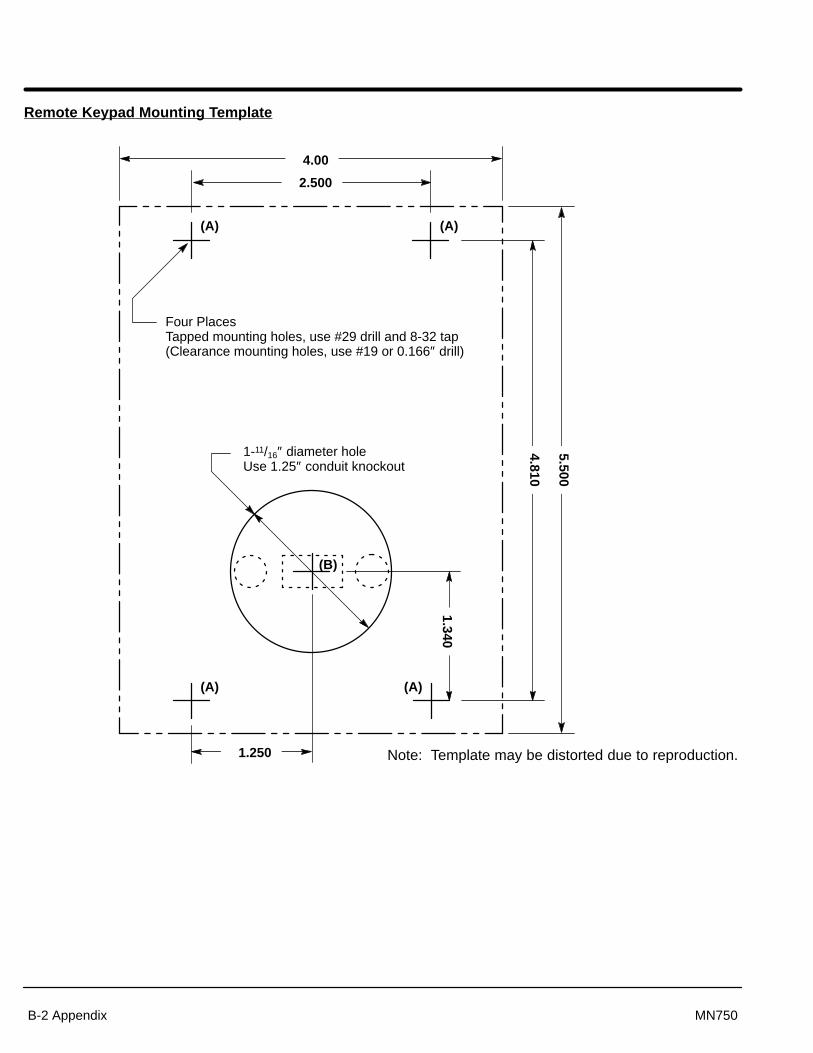
Section 1General Information
B-2 Appendix MN750
Remote Keypad Mounting Template
Four PlacesTapped mounting holes, use #29 drill and 8-32 tap(Clearance mounting holes, use #19 or 0.166″ drill)
4.00
2.500
1.250
1.340
4.810
5.500
1-11/16″ diameter holeUse 1.25″ conduit knockout
(B)
(A) (A)
(A) (A)
Note: Template may be distorted due to reproduction.

BALDOR ELECTRIC COMPANYP.O. Box 2400
Ft. Smith, AR 72902–2400(501) 646–4711
Fax (501) 648–5792
Baldor Electric CompanyMN750
Printed in USA7/98 C&J2500


![[XLS] Web view1 99 2 99 3 99 4 99 5 99 6 98 7 98 8 98 9 98 10 98 11 98 12 98 13 98 14 98 15 98 16 98 17 98 18 98 19 98 20 98 21 98 22 98 23 97 24 97 25 97 26 97 27 97 28 97 29 97 30](https://static.fdocuments.in/doc/165x107/5b1e84727f8b9a116d8ba522/xls-web-view1-99-2-99-3-99-4-99-5-99-6-98-7-98-8-98-9-98-10-98-11-98-12-98-13.jpg)