MMP English Short Form cover - Keison Products - World's ... ·...
19
Modular Mains Protectors MMP Surge Protection Range
Transcript of MMP English Short Form cover - Keison Products - World's ... ·...
UK OFFICE
Thomas & Betts Limited
Furse
Wilford Road
Nottingham
NG2 1EB
United Kingdom
Switchboard +44 (0)115 964 3700
Fax +44 (0)115 986 0538
Sales tel +44 (0)115 964 3800
Sales fax +44 (0)115 986 0071
Email: [email protected]
www.furse.com
EUROPEAN HEADQUARTERS
Thomas & Betts
200 Chaussée de Waterloo
B-1640 Rhode-St-Genèse
Belgium
Tel +32 (0)2 359 8200
Fax +32 (0)2 359 8201
www.tnb-europe.com
MIDDLE EAST OFFICE
Thomas & Betts Ltd. Br.
Office 107 5EA East Wing
Dubai Airport Free Zone
PO Box 54567
Dubai
United Arab Emirates
Tel +971 (0)4 609 1635
Fax +971 (0)4 609 1636
Email: [email protected]
SOUTH EAST ASIA OFFICE
Thomas & Betts Asia (Singapore) Pte Ltd
10 Ang Mo Kio Street 65
#06-07 Techpoint
Singapore 569059
Tel +65 6720 8828
Fax +65 6720 8780
Email: [email protected]
The content of this Thomas & Betts catalogue has been carefully checked for accuracy at the time of print. However, Thomas & Bettsdoesn’t give any warranty of any kind, express or implied, in this respect and shall not be liable for any loss or damage that may resultfrom any use or as a consequence of any inaccuracies in or any omissions from the information which it may contain. E&OE.
Copyright Thomas & Betts 2009. Copyright in these pages is owned by Thomas & Betts except where otherwise indicated. No part ofthis publication may be reproduced, copied or transmitted in any form or by any means, without our prior written permission. Images,trade marks, brands, designs and technology are also protected by other intellectual property rights and may not be reproduced orappropriated in any manner without written permission of their respective owners. Thomas & Betts reserves the right to change andimprove any product specifications or other mentions in the catalogue at its own discretion and at any time. These conditions of use aregoverned by the laws of the Netherlands and the courts of Amsterdam shall have exclusive jurisdiction in any dispute.
MMP-UK-CAT-0709
Modular Mains ProtectorsMMP Surge Protection Range

Furse is a world leader in the design,
manufacture and supply of earthing and
lightning protection systems. Combining over
100 years’ technical expertise with an enviable
reputation for innovation, quality and service,
Furse is uniquely placed to provide a ‘Total
Solution’ to all your earthing, lightning and
transient overvoltage protection needs.
Since 1998, the Furse brand has been included in the
product portfolio of the Thomas & Betts Corporation.
Thomas & Betts was founded in New York in 1898.
The corporate headquarters now reside in Memphis,
Tennessee with the company being listed on the New
York stock exchange. Thomas & Betts has now over
100 years’ experience of successfully supplying
quality products to the market by using innovative
design and manufacturing techniques. A truly global
player having a presence in Europe, North & Central
America, Australia and the Far & Middle East.
Worldwide 13,000 employees are dedicated to
ensuring that Thomas & Betts is fast, flexible and
customer focused.
Whilst one of our core markets remains in electrical
products, Thomas & Betts also has leading brands
along with significant market share in emergency
lighting and fire detection systems, steel structures,
communications, electronic systems protection,
earthing and lightning protection. In recent years,
Thomas & Betts has developed a formidable
European safety products division. This division serves
as a key knowledge platform, focusing on continued
product innovation and delivery of competitive
solutions to our customers. Furse, being one of the
leading brands within this division, benefits from
economies of scale in product development and
production, facilitating the further efficient
development of earthing, lightning protection and
electronic surge protection systems.
Home to many well known brands and with over 100 years experience, Thomas & Betts provides a truly world-classlevel of quality, service and support. The electrical division in Europe provides the following key products:
Electrical products
An impressive range of high quality products
to fasten, install, insulate, protect and connect
electrical cables, with the confidence to achieve
a highly professional result.
Premium cable ties for the most demanding
applications, including the Ty-Rap® cable ties with a
steel locking barb and the Ty-Met™ self-locking
stainless steel ties.
A wide variety of multi-purpose heat shrink tubing
for use in insulation, protection, identification and
strain relief.
A broad range of solderless termination systems
for a variety of applications, including power
cables, shielded cables and magnet wire.
A range of liquidtight flexible conduits & fittings
for the protection of electrical cables in industrial
applications, in metallic and non-metallic versions
(including Nylon conduits & fittings).
A new range of cast resin joints for splicing and
branching low voltage cables, in applications like
street, leisure and airfield lighting, utility & home
connections.
A range of spring steel fasteners for quick, easy
and reliable fixing of services to steelwork.
Earthing & Lightningprotection solutions
With Furse, T&B is leading in the design,
manufacture and supply of earthing and
lightning protection systems.
Through its range of products, Furse can provide
complete and innovative solutions for lightning
protection, surge protection and earthing
applications.
Safety equipment forhazardous areas
DTS specializes in the provision of advanced safety
lighting solutions for hazardous and hostile areas to
a wide variety of industrial markets, including
drilling, marine, oil & gas and pharmaceutical.
Street and amenity lightingcontrol equipment
Royce Thompson is a leading manufacturer of
high quality, reliable and energy efficient photo-
electronic lighting control equipment for street and
amenity lighting.
Emergency lighting &fire detection systems
Throughout Europe T&B is well represented on
the emergency lighting and fire detection
markets with various leading brands providing
dedicated solutions for safe evacuation of
buildings and sites.
Emergi-Lite Safety Systems is the provider of
advanced emergency lighting and fire detection
systems, with field project support at the design
stage through to commissioning and maintenance.
The emergency lighting engineers, providing
innovation and the latest technology to the OEM
lighting industry.
Kaufel, formerly known as NIFE, is a strong brand
in emergency lighting products and safety power
supply systems, among whose product brands are
Sentara, Venter and Twister.
Kaufel supplies a complete range of dedicated
emergency lighting luminaries and central battery
and testing systems with product brands like Brio,
Elitt and Sesam.
VanLien provides a wide range of emergency
lighting solutions, ranging from luminaries to
central battery systems with product brands like
Optilux, Aqualux and Serenga.

Nominal Maximum Continuous Phase Installation MMP BB MMP C DescriptionVoltage (Un) Operating Voltage (Uc) Imax = 150kA Imax = 40kA
Iimp = 25kA
220 - 240VRMS 275VRMS 1 TN-C, IT MMP B275B/1 MMP C275/1 Single Phase (L-E)
1 TN-S, TN-C-S MMP B275B/2 MMP C275/2 Single Phase (L-E) + N
1 TT MMP B275B/1+1T MMP C275/1+1T Single Phase (L-N)(Gas discharge tube N-E)
3 TN-C, IT MMP B275B/3 MMP C275/3 Three Phase (L-E)
3 TN-S, TN-C-S MMP B275B/4 MMP C275/4 Three Phase (L-E) + N
3 TT MMP B275B/3+1T MMP C275/3+1T Three Phase (L-N)(Gas discharge tube N-E)
1
Contents
Contents
Introduction 2 - 3What are transient overvoltages and why you need protection
Classification of Surge Protection Devices 4Comparison between VDE and IEC location categories and which MMP protector is relevant
Wiring system overview 5An overview of the wiring system diagrams showing how to connect MMP protectors
Protectors 6 - 16Full product details of the entire range of Furse MMP modular transient overvoltage protectors
Selecting the right protector for your 230V system*
Product range overview
The Furse MMP Series protectors are suitable for use on single or three phase mains supplies and powerdistribution systems. The varistor based design eliminates the high follow current (If) associated withspark gap based surge protection. The series consists of the following products:
MMP BB Series Type 1 (Class I/Class B) protectors
For protecting against partial direct or indirect lightning strikes, Imax = 150kA 8/20µs, Iimp = 25kA 10/350µs
Redundancy, indicates if unit is partially or fully damaged
MMP C Series Type 2 (Class II/Class C) protectors
For protecting against indirect lightning strikes, Imax = 40kA 8/20µs
MMP D Series Type 3 (Class III/Class D) protectors
For protecting against indirect lightning strikes, Imax = 10kA 8/20µs
3 mode protection; L-N, L-PE and N-PE
A range of compact MMP protectors (2BA, 1B, and 2C Series) is also available.* Protectors are available for all system voltages.

Introduction | What are transient overvoltages and why do you need protection?
2
What are transient overvoltagesand why do you need protection?
CausesTransient overvoltages can be caused by:
the secondary effects of lightning strikes (eitherbetween clouds or to ground) from a kilometreor more away
the electrical switching of large inductive loads(such as motors, transformers and electricaldrives), or capacitative loads (such as powerfactor correction)
Transientovervoltagedamage to thecircuit board, left,is clear to see, butmost damage isbarely visible,as below.
Transient overvoltages are large, very brief and potentially destructive increases in voltage.
Devastating effectsAlthough they last only thousandths ormillionths of a second, transient overvoltagescan devastate modern electronic systems:
disrupting system operations, through dataloss, data and software corruption andunexplained crashes
degrading equipment components andcircuitry, shortening equipment lifetimeand increasing failures
destroying components, circuit boards andI/O cards
causing costly and unnecessary system downtime

3
What are transient overvoltages and why do you need protection? | Introduction
What are transient overvoltagesand why do you need protection?
Growing threatThe miniaturisation of electronic components and circuits makes systems ever more susceptible to damage, and thegrowing use of electronic systems further increases our vulnerability to the effects of transients.
The new BS EN/IEC 62305 “Protection against lightning”standards therefore emphasize the need to protectelectronic equipment and systems to ensure safety andbusiness continuity.
Most modern electronic systems are at risk:
computers
data communication networks
building management systems
PABX telephone exchanges
CCTV equipment
fire and burglar alarms
telecom base stations
uninterruptible power supplies (UPSs)
programmable logic controllers (PLCs)
plant sensors
telemetry and data acquisition equipment
Loss of these systems would cripple industrial,commercial and government organisations alike.
Risk assessmentAlthough most of us work in buildings with lightning conductors, these aren’t designed to, and won’t, stop transientovervoltages from damaging electronic equipment. As recognised by the latest “BS EN/IEC 62305 standards”, to preventlightning damage to electronic systems, this structural lightning protection needs to be complemented with transientovervoltage protection.
The single risk assessment of BS EN/IEC 62305 encompasses protection for both the structure and its contents -human life and electronic equipment. Interestingly, the risk of transient overvoltage damage to electronic systemsinside a building is greater than the risk of damage to the building itself.
Therefore, if, like most people, you work in a building where structural lightning protection has already been thoughtnecessary, then there is a ready made argument for transient overvoltage protection.
Protection benefitsEffective transient overvoltage protection can prevent:
fire risks and electric shock hazards
health and safety hazards caused by plant instability, after loss of control
loss of essential services – fire alarm, security systems, building management systems
lost/destroyed data or equipment damage
repair work – especially costly for remote or unmanned installations
the high cost of extended stoppages – sales lost to competitors, lost production, deterioration or spoilage ofwork in progress
Example: collection area comparison
This site consists of a main building A, auxiliary buildings B and someground level sensors C, which are linked by various underground cables.The collection area for this site for a direct lightning strike is a distanceequivalent to the height of the structures laid out in plan (shown as theshaded area). The effective collection area for transient overvoltages ismuch larger. It includes a collection area associated with the surroundingground (unshaded), plus additional areas (not shown) for incomingpower and phone lines D.

Classification of Surge Protection Devices
4
Classification of Surge Protection Devices
International and European Standards IEC 61643 and EN 61643 (replacing standards such as DIN VDE0675) determine the co-ordination of surge protectors according to their location and requirements.
Type 1 (Class I/Class B) protectorsLocated at an area where high lightning currents are expected. Typically fitted to provide equipotential bondingat the service entrance (main distribution board).
Type 2 (Class II/Class C) protectorsLocated at sub-distribution boards to control overvoltages, often residual voltages, from the upsteam Class Ilightning current arrestors.
Type 3 (Class III/Class D) protectorsLocated close to the equipment, typically at the socket outlet, they provide local protection by limiting overvoltagescaused by switching operations to safe levels.
Surge protection devices must provide a level of protection below the withstand voltage of equipment to preventequipment damage. The withstand voltage depends on the type of equipment and its sensitivity.
These withstand levels are defined in 4 overvoltage categories by IEC 60664 as shown below.
Using a co-ordinated set of protectors, as offered by the Furse MMP Series, optimum protection from damage toequipment is achieved.
For protection of highly critical and sensitive equipment, where continual operation is necessary
Type 1 Type 2 Type 3
MMP Product MMP B275B Series MMP C275 Series MMP D275 SeriesMMP CN275 Series
Classification- EN 1 2 3- IEC I II III- VDE B C D
Protection category(defined in IEC 60664)
(6kV) (4kV) (2.5kV) (1.5kV)
230/400V MDB Meter Socket Local protection
A range of compact MMP protectors (2BA, 1B, and 2C Series) is also available.
IV III II I
kWh Equipment

5
Wiring system overview
Wiring system overview
The following wiring diagrams detail how to connect the Furse MMP BB, C, CN and D Series protectors for thecommon types of mains wiring installations. For more details and to see the direct comparisons across the range,please refer to the MMP Product Selector Chart on page 1.
L
L
L
PEN
1
2
3
L
L
L
PEN
1
2
3
L
L
L
N
PE
1
2
3
L
L
L
N
PE
1
2
3
L
L
L
N
PEN
1
2
3
L
L
L
N
PE
1
2
3
L
L
L
N
1
2
3
L
L
L
N
1
2
3
TN-C NetworksFor systems with a combined Neutral/Earth supplyconductor (PEN).
TN-S NetworksFor systems with separate Neutral/Earth supplyconductors (PE & N).
TN-C-S NetworksFor systems with a combined Neutral/Earth supplyconductor that is split locally to provide a separatedNeutral conductor (PEN, PE & N).
TT NetworksFor systems where only Live and Neutral conductorsare provided from the mains supply. An Earth forthe equipment is provided locally. Surge protectionbetween Neutral/Earth can be offered by a spark gap(GDT) device to provide galvanic isolation betweenthe Neutral supply and local Earth conductors.

6
MMP BB Series – 1 phase | Type 1 (Class I/Class B) protectors
MMP BB Series – 1 phase
Wiring diagramsThe diagrams below illustratehow to wire the MMP protectoraccording to your chosenelectrical system.
Specification Type 1 (Class I/Class B) protector
Imax = 150kA 8/20µs
Iimp = 25kA 10/350µs
ApplicationUse on single or three phase mains supplies and power distribution systemsfor protection against partial direct or indirect lightning strikes.
InstallationShould be installed in a main distribution panel. The protector is suitablefor attachment to a 35mm top hat DIN rail.
Features and benefits The varistor based design eliminates the high follow current (If)
associated with spark gap based surge protection
Two red indicators show when the protector requires replacement
If only one indicator is displayed then there is still limited protectionoffered by the unit
This indication can also trigger a remote signal contact to interfacewith a building management system. Please use ‘/S’ after the part no.to order the remote indication (normally-open) contact version
L
PEN
L
250 AgLfusing
Mai
ndi
strib
utio
nbo
ard
L
N
PE
L NMai
ndi
strib
utio
nbo
ard
250 AgLfusing
L
PEN
L N
L
N
PE
Mai
ndi
strib
utio
nbo
ard
250 AgLfusing
L
N
PE
N N
L NMai
ndi
strib
utio
nbo
ard
250 AgLfusing
TN-C
TN-S
TN-C-S
TT
Compact Type 1(Class I/Class B) protectorsA range of compact Type 1 (Class I/Class B) protectorsis available from Furse.See page 16 for a brief summary of each protectortype

7
MMP BB Series – 1 phase
Type 1 (Class I/Class B) protectors | MMP BB Series – 1 phase
MMP B275B/1 MMP B275B/2 MMP B275B/1+1T
Electrical specificationInstallation TNC TNS/TNCS TT
Nominal voltage* 220 - 240VRMS 220 - 240VRMS 220 - 240VRMS
Maximum continuous operating voltage (Uc) 275Vac / 350Vdc 275Vac / 350Vdc 275Vac / 350Vdc
Back up fuse(If mains supply >100A)
250AgL 250AgL 250AgL
Short circuit capability 25kA / 50Hz 25kA / 50Hz 25kA / 50Hz
Signal contact ratingsSignal contact part no.
250VRMS / 0.5AMMP B275B/1/S
250VRMS / 0.5AMMP B275B/2/S
250VRMS / 0.5AMMP B275B/1+1T/S
Transient specificationArrestor classification1
ENIECE DIN VDE 0675
1 (1 + 2)I (I + II)
B (B + C)
1 (1 + 2)I (I + II)
B (B + C)
1 (1 + 2)I (I + II)
B (B + C)
Let-through voltage (Up)2
at In (8/20µs)at Iimp (10/350µs)at 1.2/50µs
<1.6kV<1.0kV
–
<1.6kV<1.0kV
–
<1.6kV<1.0kV<1.2kV
Nominal discharge currentIn (8/20µs) 70kA 70kA 70kA
Maximum discharge currentImax (8/20µs)Iimp (10/350µs)
150kA25kA
150kA25kA
150kA25kA / 100kA (N-E)
1 Tested to BS EN/IEC-616432 Values stated are per pole
Mechanical specificationTemperature range -40 to +80ºC
Connectionfor powerfor signal
35mm2 solid conductor, 25mm2 stranded conductor1.5mm2 conductor (/S Option)
Mounting Indoor, 35mm top hat DIN rail
Degree of protection IP20
Case material Thermoplastic, UL 94 V-0
Dimensionsto DIN 43880 90mm x 68mm x 36mm (2TE) 90mm x 68mm x 72mm (4TE) 90mm x 68mm x 72mm (4TE)
Height with remote signal contact =100mm
90 mm
36 mm
2TE
Standarddepth 68 mm
90 mm
72 mm
4TE
Enclosure dimensionsfor up to 4TE wide 170mm x 98mm x 105mm (MMP ENC4)
8
MMP BB Series – 3 phase | Type 1 (Class I/Class B) protectors
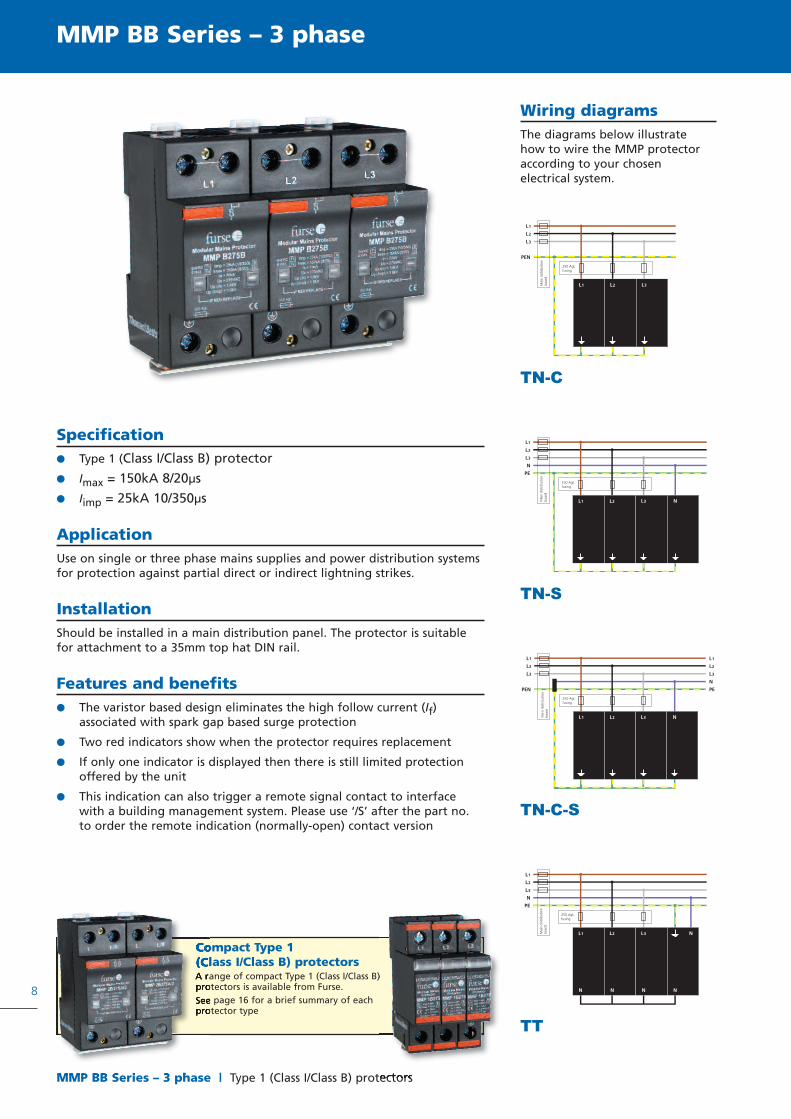
MMP BB Series – 3 phase
Wiring diagramsThe diagrams below illustratehow to wire the MMP protectoraccording to your chosenelectrical system.
Specification Type 1 (Class I/Class B) protector
Imax = 150kA 8/20µs
Iimp = 25kA 10/350µs
ApplicationUse on single or three phase mains supplies and power distribution systemsfor protection against partial direct or indirect lightning strikes.
InstallationShould be installed in a main distribution panel. The protector is suitablefor attachment to a 35mm top hat DIN rail.
Features and benefits The varistor based design eliminates the high follow current (If)
associated with spark gap based surge protection
Two red indicators show when the protector requires replacement
If only one indicator is displayed then there is still limited protectionoffered by the unit
This indication can also trigger a remote signal contact to interfacewith a building management system. Please use ‘/S’ after the part no.to order the remote indication (normally-open) contact version
L
L
L
PEN
1
2
3
L1 L2 L3
250 AgLfusing
Mai
ndi
strib
utio
nbo
ard
L
L
L
N
PE
1
2
3
L1 L2 L3 NMai
ndi
strib
utio
nbo
ard
250 AgLfusing
L
L
L
PEN
1
2
3
L1 L2 L3 N
L
L
L
N
PE
1
2
3
Mai
ndi
strib
utio
nbo
ard
250 AgLfusing
L
L
L
N
PE
1
2
3
N N N N
L1 NL3L2
250 AgLfusing
Mai
ndi
strib
utio
nbo
ard
TN-C
TN-S
TN-C-S
TT
Compact Type 1(Class I/Class B) protectorsA range of compact Type 1 (Class I/Class B)protectors is available from Furse.See page 16 for a brief summary of eachprotector type

9
MMP BB Series – 3 phase
Type 1 (Class I/Class B) protectors | MMP BB Series – 3 phase
MMP B275B/3 MMP B275B/4 MMP B275B/3+1T
Electrical specificationInstallation TNC TNS/TNCS TT
Nominal voltage* 220 - 240VRMS 220 - 240VRMS 220 - 240VRMS
Maximum continuous operating voltage (Uc) 275Vac / 350Vdc 275Vac / 350Vdc 275Vac / 350Vdc
Back up fuse(If mains supply >100A)
250AgL 250AgL 250AgL
Short circuit capability 25kA / 50Hz 25kA / 50Hz 25kA / 50Hz
Signal contact ratingsSignal contact part no.
250VRMS / 0.5AMMP B275B/3/S
250VRMS / 0.5AMMP B275B/4/S
250VRMS / 0.5AMMP B275B/3+1T/S
Transient specificationArrestor classification1
ENIECE DIN VDE 0675
1 (1 + 2)I (I + II)
B (B + C)
1 (1 + 2)I (I + II)
B (B + C)
1 (1 + 2)I (I + II)
B (B + C)
Let-through voltage (Up)2
at In (8/20µs)at Iimp (10/350µs)at 1.2/50µs
<1.6kV<1.0kV
–
<1.6kV<1.0kV
–
<1.6kV<1.0kV<1.2kV
Nominal discharge currentIn (8/20µs) 70kA 70kA 70kA
Maximum discharge currentImax (8/20µs)Iimp (10/350µs)
150kA25kA
150kA25kA
150kA25kA / 100kA (N-E)
1 Tested to BS EN/IEC-616432 Values stated are per pole
Mechanical specificationTemperature range -40 to +80ºC
Connectionfor powerfor signal
35mm2 solid conductor, 25mm2 stranded conductor1.5mm2 conductor (/S Option)
Mounting Indoor, 35mm top hat DIN rail
Degree of protection IP20
Case material Thermoplastic, UL 94 V-0
Dimensionsto DIN 43880 90mm x 68mm x 108mm (6TE) 90mm x 68mm x 144mm (8TE) 90mm x 68mm x 144mm (8TE)
Height with remote signal contact =100mm
90 mm
108 mm
6TE
Standarddepth
68 mm
90 mm
144 mm
8TE
Enclosure dimensionsfor up to 8TE wide 180mm x 98mm x 180mm (MMP ENC8)
10
MMP C + CN Series – 1 phase | Type 2 (Class II/Class C) protectors
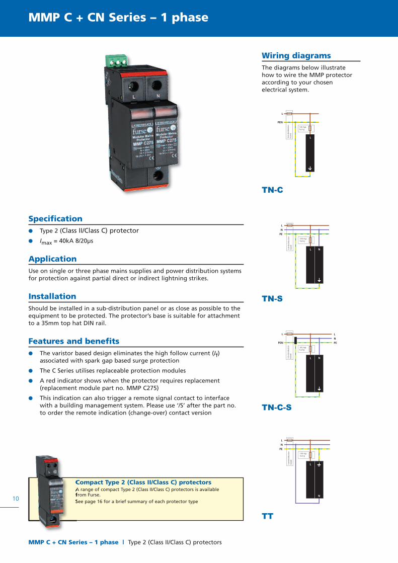
MMP C + CN Series – 1 phase
Wiring diagramsThe diagrams below illustratehow to wire the MMP protectoraccording to your chosenelectrical system.
Specification Type 2 (Class II/Class C) protector
Imax = 40kA 8/20µs
ApplicationUse on single or three phase mains supplies and power distribution systemsfor protection against partial direct or indirect lightning strikes.
InstallationShould be installed in a sub-distribution panel or as close as possible to theequipment to be protected. The protector’s base is suitable for attachmentto a 35mm top hat DIN rail.
Features and benefits The varistor based design eliminates the high follow current (If)
associated with spark gap based surge protection
The C Series utilises replaceable protection modules
A red indicator shows when the protector requires replacement(replacement module part no. MMP C275)
This indication can also trigger a remote signal contact to interfacewith a building management system. Please use ‘/S’ after the part no.to order the remote indication (change-over) contact version
PEN
L
L
100 AgLfusing
Sub-
dist
ribut
ion
boar
d
L
N
PE
L N
100 AgLfusing
Sub-
dist
ribut
ion
boar
d
L N
L
PEN
L
N
PE
100 AgLfusing
Sub-
dist
ribut
ion
boar
d
L
N
PE
N
L
100 AgLfusing
Sub-
dist
ribut
ion
boar
d
TN-C
TN-S
TN-C-S
TT
Compact Type 2 (Class II/Class C) protectorsA range of compact Type 2 (Class II/Class C) protectors is availablefrom Furse.See page 16 for a brief summary of each protector type

11
MMP C + CN Series – 1 phase
Type 2 (Class II/ Class C) protectors | MMP C + CN Series – 1 phase
MMP C275/1 MMP C275/2 MMP C275/1+1T
Electrical specificationInstallation TNC TNS/TNCS TT
Nominal voltage* 220 - 240VRMS 220 - 240VRMS 220 - 240VRMS
Maximum continuous operating voltage (Uc) 275Vac / 350Vdc 275Vac / 350Vdc 275Vac / 350Vdc
Back up fuse(If mains supply >100A)
100AgL 100AgL 100AgL
Short circuit capability 25kA / 50Hz 25kA / 50Hz 25kA / 50Hz
Signal contact ratingsSignal contact part no.Non-replaceable SPD part no.Non-replaceable SPD signal contact part no.
250VRMS / 0.5AMMP C275/1/SMMP CN275/1MMP CN275/1/S
250VRMS / 0.5AMMP C275/2/SMMP CN275/2MMP CN275/2/S
250VRMS / 0.5AMMP C275/1+1T/SMMP CN275/1+1TMMP CN275/1+1T/S
Transient specificationArrestor classification1
ENIECE DIN VDE 0675
2IIC
2IIC
2IIC
Let-through voltage (Up)2
at In (8/20µs)at Iimp (10/350µs), N-Eat 1.2/50µs
<0.9kV––
<0.9kV––
<0.9kV<1.3kV<1.2kV
Nominal discharge currentIn (8/20µs) 20kA 20kA 20kA
Maximum discharge currentImax (8/20µs)Iimp (10/350µs)
40kA–
40kA–
40kA12.5kA (N-E)
1 Tested to BS EN/IEC-616432 Values stated are per pole
Mechanical specificationTemperature range -40 to +80ºC
Connectionfor powerfor signal
35mm2 solid conductor, 25mm2 stranded conductor1.5mm2 conductor (/S Option)
Mounting Indoor, 35mm top hat DIN rail
Degree of protection IP20
Case material Thermoplastic, UL 94 V-0
Dimensionsto DIN 43880 90mm x 68mm x 17mm (1TE) 90mm x 68mm x 36mm (2TE) 90mm x 68mm x 36mm (2TE)
Height with remote signal contact =100mm
90 mm
17 mm
90 mm
36 mm
1TE 2TE
Standarddepth 68 mm
Enclosure dimensionsfor up to 4TE wide 170mm x 98mm x 105mm (MMP ENC4)
12
MMP C + CN Series – 3 phase | Type 2 (Class II/Class C) protectors
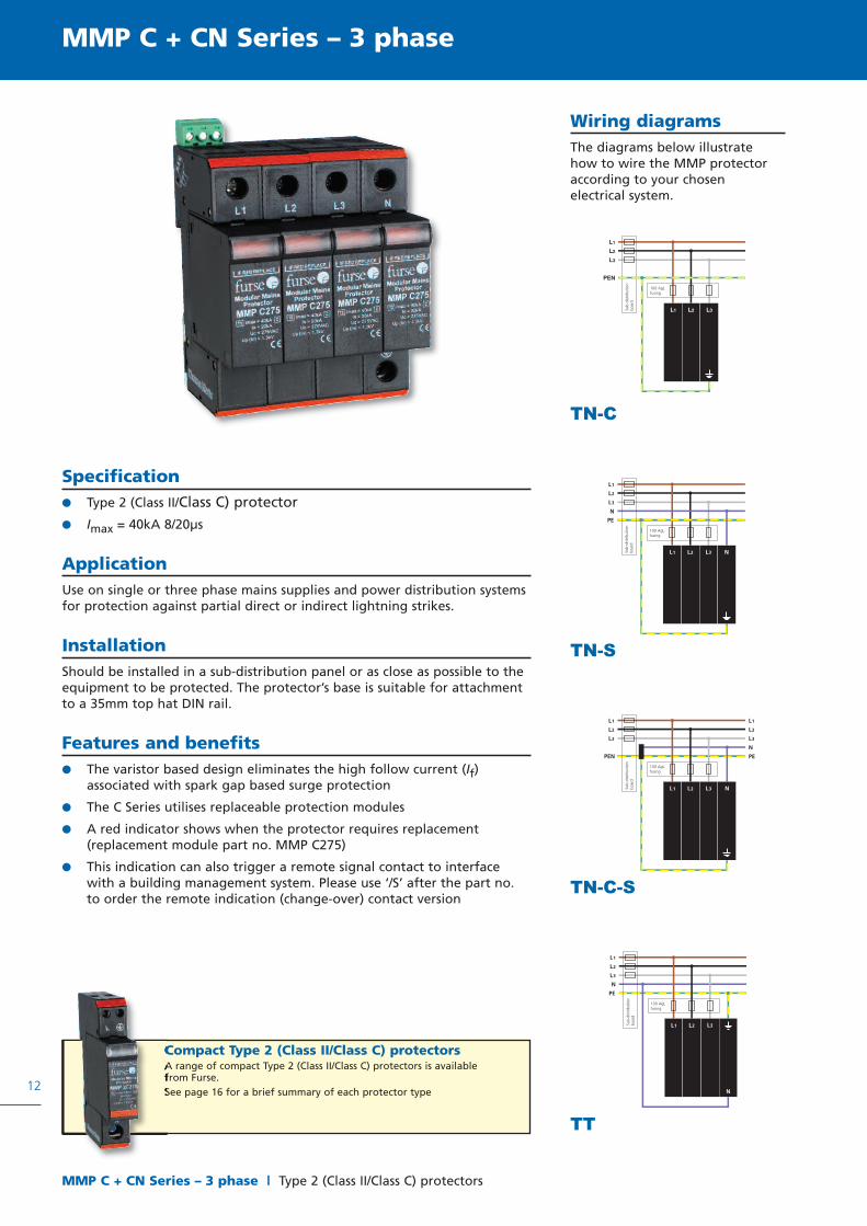
MMP C + CN Series – 3 phase
Wiring diagramsThe diagrams below illustratehow to wire the MMP protectoraccording to your chosenelectrical system.
Specification Type 2 (Class II/Class C) protector
Imax = 40kA 8/20µs
ApplicationUse on single or three phase mains supplies and power distribution systemsfor protection against partial direct or indirect lightning strikes.
InstallationShould be installed in a sub-distribution panel or as close as possible to theequipment to be protected. The protector’s base is suitable for attachmentto a 35mm top hat DIN rail.
Features and benefits The varistor based design eliminates the high follow current (If)
associated with spark gap based surge protection
The C Series utilises replaceable protection modules
A red indicator shows when the protector requires replacement(replacement module part no. MMP C275)
This indication can also trigger a remote signal contact to interfacewith a building management system. Please use ‘/S’ after the part no.to order the remote indication (change-over) contact version
100 AgLfusing
Sub-
dist
ribut
ion
boar
d
L
L
L
N
PE
1
2
3
L1 L2 L3 N
100 AgLfusing
Sub-
dist
ribut
ion
boar
d
L1 L2 L3 N
L
L
L
PEN
1
2
3
L
L
L
N
PE
1
2
3
100 AgLfusing
Sub-
dist
ribut
ion
boar
d
L
L
L
N
PE
1
2
3
N
L1 L2 L3
100 AgLfusing
Sub-
dist
ribut
ion
boar
d
TN-C
TN-S
TN-C-S
TT
Compact Type 2 (Class II/Class C) protectorsA range of compact Type 2 (Class II/Class C) protectors is availablefrom Furse.See page 16 for a brief summary of each protector type

13
MMP C + CN Series – 3 phase
Type 2 (Class II/Class C) protectors | MMP C + CN Series – 3 phase
MMP C275/3 MMP C275/4 MMP C275/3+1T
Electrical specificationInstallation TNC TNS/TNCS TT
Nominal voltage* 220 - 240VRMS 220 - 240VRMS 220 - 240VRMS
Maximum continuous operating voltage (Uc) 275Vac / 350Vdc 275Vac / 350Vdc 275Vac / 350Vdc
Back up fuse(If mains supply >100A)
100AgL 100AgL 100AgL
Short circuit capability 25kA / 50Hz 25kA / 50Hz 25kA / 50Hz
Signal contact ratingsSignal contact part no.Non-replaceable SPD part no.Non-replaceable SPD signal contact part no.
250VRMS / 0.5AMMP C275/3/SMMP CN275/3
MMP CN275/3/S
250VRMS / 0.5AMMP C275/4/SMMP CN275/4
MMP CN275/4/S
250VRMS / 0.5AMMP C275/3+1T/SMMP CN275/3+1T
MMP CN275/3+1T/S
Transient specificationArrestor classification1
ENIECE DIN VDE 0675
2IIC
2IIC
2IIC
Let-through voltage (Up)2
at In (8/20µs)at Iimp (10/350µs), N-Eat 1.2/50µs
<0.9kV––
<0.9kV––
<0.9kV<1.3kV<1.2kV
Nominal discharge currentIn (8/20µs) 20kA 20kA 20kA
Maximum discharge currentImax (8/20µs)Iimp (10/350µs)
40kA–
40kA–
40kA12.5kA (N-E)
1 Tested to BS EN/IEC-616432 Values stated are per pole
Mechanical specificationTemperature range -40 to +80ºC
Connectionfor powerfor signal
35mm2 solid conductor, 25mm2 stranded conductor1.5mm2 conductor (/S Option)
Mounting Indoor, 35mm top hat DIN rail
Degree of protection IP20
Case material Thermoplastic, UL 94 V-0
Dimensionsto DIN 43880 90mm x 68mm x 54mm (3TE) 90mm x 68mm x 72mm (4TE) 90mm x 68mm x 72mm (4TE)
Height with remote signal contact =100mm
* Protectors are availablefor all system voltages -contact Furse.
90 mm
54 mm
90 mm
72 mm
3TE 4TE
Standarddepth 68 mm
Enclosure dimensionsfor up to 4TE wide 170mm x 98mm x 105mm (MMP ENC4)

UK, US andJapan plug versionsalso available -contact Furse
UK, US andJapan plug versionsalso available -contact Furse
14
MMP D Series | Type 3 (Class III/Class D) protectors
MMP D Series
ApplicationUse on single phase mainssupplies. Use in conjunction withType 1 and Type 2 protectors forthe best possible level of surgeprotection.
InstallationPlug the protector directly intoa mains socket outlet then plugthe equipment to be protectedinto the integral socket in theprotector.
Features and benefits Varistor based design
A green indicator shows thepresence of mains voltage
A red indicator shows whenthe protection modulerequires replacement
Internal varistor componentsfeature thermal protectionelements
Operation of the protectedequipment is not interrupteddue to a damaged protectioncomponent
Specification Type 3 (Class III/Class D) protector
Imax = 10kA 8/20µs
Full mode protection; L-N, L-PE and N-PE
Electrical specification MMP D275/DE
Nominal voltage 220 - 240VRMS
Maximum continuous operating voltage (Uc) 275Vac / 350Vdc
Back up fuse 16AgL
Transient specificationArrester classification1
ENIECE DIN VDE 0675
3IIID
Let-through voltage (Up)L - N Isc (8/20µs)L/N - PE at Isc (8/20µs)
<1kV<1.5kV
Nominal discharge currentIn (8/20µs) 3kA
Maximum discharge currentImax (8/20µs) 10kA
1 Tested to BS EN/IEC-61643
Mechanical specificationTemperature range -25 to +40ºC
Connection type - Standards
Geographic Location
Schuko, DIN 49 440-CE(7)IIIDIN 49 441-CEE(7)IVEurope, see footnote 1
for exclusions
Mounting Mains outlet to above specification
Degree of protection IP20
Case material Thermoplastic, UL 94 V-0
Dimensions 72mm x 140mm x 47mm
1 Europe excluding Great Britain, France, Belgium, Poland, Slovakia, and the Czech Republic
140 mm
72 mm
Modular Mains Protector
Depth 47 mm

15
MMP D Series
Type 3 (Class III/Class D) protectors | MMP D Series
Electrical specification */ADSL */ISDN */LAN */TN */TV
Nominal voltage 135V 130V 5Vdc 130V 20V
Maximum continuous operating voltage (Uc) 175V 160V 6Vdc 180V 20V
In-line resistance (± 10%) 0.3Ω 3 - 6Ω 0.1Ω 9 - 11Ω 0.1Ω
Bandwidth >10MHz >2MHz 100MHz >1MHz >1GHz
* Prefix MMP D275/DE to create the complete part no. e.g. MMP D275/DE/ADSL
Transient specification */ADSL */ISDN */LAN */TN */TV
Let-through voltage (Up)L - N In (8/20µs)L/N - PE at In (8/20µs)
<600V<300V
<600V<300V
35V350V
<600V<600V
<600V<600V
Nominal discharge currentL - N Isn (8/20µs)L/N - PE at Isn (8/20µs)
2.5kA5kA
2.5kA5kA
300A300A
2.5kA5kA
5kA5kA
* Prefix MMP D275/DE to create the complete part no. e.g. MMP D275/DE/ADSL
Mechanical specification */ADSL */ISDN */LAN */TN */TV
Connection type RJ45 RJ45 RJ45 (UTP) RJ11 Euro-TV
* Prefix MMP D275/DE to create the complete part no. e.g. MMP D275/DE/ADSL
Combined D Series protectorsIn addition to the standard D Series protector, Furse also offers the following combined protectors:
MMP D275/DE/ADSL
Mains protector with integral ADSL protection via RJ45 socket
MMP D275/DE/ISDN
Mains protector with integral ISDN protection via RJ45 socket
MMP D275/DE/LAN
Mains protector with integral LAN protection via RJ45 socket
MMP D275/DE/TN
Mains protector with integral telephone protection via RJ11 socket
MMP D275/DE/TV
Mains protector with integal EURO-TV protection via antenna signal socket
Combined protector technical specification:

16
Compact MMP protectors
Compact MMP protectors
MMP 2BA Type 1 (Class I/B) protector Imax = 80kA 8/20µs
Iimp = 12.5kA 10/350µs
Install in main distribution panel
Red indicator shows when the protection module requires replacement
Can also trigger a remote signal contact to interface with a buildingmanagement system (‘/S’ part no.)
MMP 1B Series Type 1 (Class I/B) protector Imax = 60kA 8/20µs
Iimp = 10kA 10/350µs
Install in main distribution panel
Red indicators show when the protector requires replacement(replacement module part no. MMP 1BXXX where XXX is the systemvoltage - 150, 275 or 385)
Can also trigger a remote signal contact to interface with a buildingmanagement system (‘/S’ part no.)
MMP 2C Series Type 2 (Class II/C) protector Imax = 40kA 8/20µs
Install in sub-distribution panel or as close as possible to the equipmentto be protected
Red indicator shows when the protector requires replacement(replacement module part no. MMP 2CXXX where XXX is the systemvoltage - 150, 275 or 385)
Can also trigger a remote signal contact to interface with a buildingmanagement system (‘/S’ part no.)
In addition to our standard MMP protectors, Furse offers a range of compact protectors for use onsingle or three phase mains supplies & power distribution systems to protect against partial direct orindirect lightning strikes.
These slimline, varistor based protectors are all designed to eliminate the high follow current (If) associated withspark gap based surge protection, and are suitable for attachment to a 35mm top hat DIN rail. Each protector hasfailure warning incorporated as standard, with easy relacement of modules as required.

Thank you for reading this data sheet.
For pricing or for further information, please contact us at our UK Office, using the details below.
UK OfficeKeison Products,
P.O. Box 2124, Chelmsford, Essex, CM1 3UP, England.Tel: +44 (0)330 088 0560Fax: +44 (0)1245 808399
Email: [email protected]
Please note - Product designs and specifications are subject to change without notice. The user is responsible for determining the suitability of this product.