MMJ 1113 FINITE ELEMENT METHOD FEM in Elasticityfkm.utm.my/~taminmn/pdf-files/FEM...
37
MMJ 1113 FINITE ELEMENT METHOD FEM in Elasticity Task: To derive the element stiffness matrix for a 3-node triangular element under plane stress / plane strain condition in elasticity. Requirements: Constitutive equations (Generalized stress-strain relations) For variational approach - Examine the functional (based on potential energy) Minimize the functional - yield finite element equations: [k]{δ} = {f} Finite Element in Elasticity
Transcript of MMJ 1113 FINITE ELEMENT METHOD FEM in Elasticityfkm.utm.my/~taminmn/pdf-files/FEM...

MMJ 1113 FINITE ELEMENT METHODFEM in Elasticity
Task:To derive the element stiffness matrix for a 3-node triangular element under plane stress / plane strain condition in elasticity.
Requirements:Constitutive equations (Generalized stress-strain relations)
For variational approach- Examine the functional (based on potential energy)
Minimize the functional - yield finite element equations: [k]δ = f
Finite Element in Elasticity

MMJ 1113 FINITE ELEMENT METHODFEM in Elasticity
General state of stress, strain and displacement at a point in a continuous body
x
τxy
τxz
τyzσx
σyy
z
=
yz
xz
xy
z
y
x
γγγεεε
ε componentsstrain
=
yz
xz
xy
z
y
x
τττσσσ
σ components stress
yw
zv
xw
zu
xu
xz ∂∂
+∂∂
=∂∂
+∂∂
=∂∂
+∂∂
=
∂∂
=∂∂
=∂∂
=
yzxy
zyx
, , xv
yu
zw ,
yv , :ndeformatio smallFor
γγγ
εεε
( )( )( )
=
zyxwzyxvzyxu
,,,,,,
componentsnt Displaceme δ

MMJ 1113 FINITE ELEMENT METHODFEM in Elasticity
Elasticity Stress tensor
Hook's law for an isotropic material undergoing infinitesimal deformation.
Strain tensor
zxxz
zyyz
yxxy
zzzyzy
yzyyyx
xzxyxx
ij
ττττττ
στττστττσ
σ===
= where
zxxz
zyyz
yxxy
zzzyzx
yzyy
yx
xzxyxx
ij
γγγγγγ
εγγ
γε
γ
γγε
ε===
= where
22
22
22
==
=
Ε−
Ε+
=
ji if 0ji if 1
:deltakronecker
1
ijδ
σδνσνε kkijijij
⁄

MMJ 1113 FINITE ELEMENT METHODFEM in Elasticity
Under Plane stress condition
Under Plane strain condition.
Non-zero strain components
Inverted for stress (Plane stress)
( ) ( ) 0 , 0 , 0 zxxzyz ===== ττττσ zyzz
( ) ( ) 0 , 0 , 0 zxxzyz ===== γγγγε zyzz
( )( )
( )( )
( )( )
xyxy
yyxxzzzz
xxzzyyyy
zzyyxxxx
τνγ
σσνσε
σσνσε
σσνσε
Ε+
=
+−Ε
=
+−Ε
=
+−Ε
=
12
1
1
1
( )
( )
( ) xyxy
zz
yyxxyy
yyxxxx
E γν
τ
σ
ενεν
σ
νεεν
σ
+=
=
+−Ε
=
+−Ε
=
12
01
1
2
2

MMJ 1113 FINITE ELEMENT METHODFEM in Elasticity
Constitutive equations - Generalized Hook's Law
For a homogenous, isotropic material:
( )( )
−
−
−−
−−
−+Ε
=
yz
xz
xy
z
y
x
yz
xz
xy
z
y
x
γγγεεε
ν
ν
νννν
νννννν
νν
τττσσσ
22100000
02210000
00221000
000100010001
211
[ ] [ ] matrix elasticityor material a is C whereεσ C=

MMJ 1113 FINITE ELEMENT METHODFEM in Elasticity
Finite Element in Elasticity
Scope of lecture:Derivation of element equations based on the minimum potential energy principle.Displacement method.
Combination of boundary disp. and tractions
Equilibrium boundary tractions
Displacement compatibility
Along inter element boundary
Continuous stress and displacement
Continuous and equilibrating stress
Continuous displacement
Inside each element
Reissner’s principleMin. Complementary energy
Min. Potential energyVariable Principle
MixedForce or equilibriumDisplacement or compatibility
Model Method
MMJ 1113 FINITE ELEMENT METHODFEM in Elasticity
LET US REVIEW THE DERIVATION OF ELEMENT EQUATIONS FOR CONSTANT STRAIN TRIANGULAR (CST) ELEMENT
Keywords:
Variational approach
Minimum potential energy principle

MMJ 1113 FINITE ELEMENT METHODFEM in Elasticity
FE formulation for two-dimensional problems
=
=
3
2
1
3
2
1
6
5
4
3
2
1
vvvuuu
δδδδδδ
δ
12
3
u1u2
u3
v2
v3
v1
y
x
Displacement modelTriangular 3-node element
( ) ( )( )
=yxvyxue
,,
δ
MMJ 1113 FINITE ELEMENT METHODFEM in Elasticity
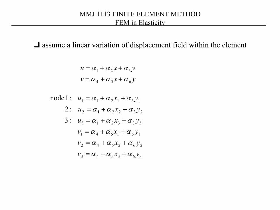
yxvyxu
654
321
αααααα
++=++=
assume a linear variation of displacement field within the element
363543
262542
161541
333213
232212
131211
:3 :2 :1 node
yxvyxvyxvyxuyxuyxu
αααααααααααααααααα
++=++=++=++=++=++=

MMJ 1113 FINITE ELEMENT METHODFEM in Elasticity
( ) ( ) ( )yucucucxubububuauauau 332211332211332211 21
21
21
++∆
+++∆
+++∆
=
where
123312231
213132321
122133113223321
c , c , b , b ,
, ,
xxxxxxcyyyyyyb
yxyxayxyxayxyxa
−=−=−=−=−=−=−=−=−=
( ) ( ) ( )yvcvcvcxvbvbvbvavavav 332211332211332211 21
21
21
++∆
+++∆
+++∆
=
area of ∆ element33
22
11
111
21
yxyxyx
=
( ) 1,2,3i , 21
332211
332211
=++∆
=
++=++=
ycxbaN
vNvNvNvuNuNuNu
iiiiNi’s are interpolation functions.

MMJ 1113 FINITE ELEMENT METHODFEM in Elasticity
[ ] δδ Ν=
ΝΝΝ
ΝΝΝ=
Ν+Ν+Ν=Ν+Ν+Ν=
~
000000
3
3
2
2
1
1
321
321
332211
332211
vuvuvu
vu
vvvvuuuu
Displacement field
The linear interpolation model satisfies both compatibility andcompleteness requirements

MMJ 1113 FINITE ELEMENT METHODFEM in Elasticity
Strain–displacement relationships
∂Ν∂
∂Ν∂
∂Ν∂
∂Ν∂
∂Ν∂
∂Ν∂
∂Ν∂
∂Ν∂
∂Ν∂
∂Ν∂
∂Ν∂
∂Ν∂
=
∂∂
+∂∂∂∂∂∂
=
=
3
3
2
2
1
1
332211
321
321
vuvuvu
xyxyxy
yyy
xxx
yu
xvyvxu
xy
y
x
γεε
ε
[ ] δε Β=
0 0
0
0
00

MMJ 1113 FINITE ELEMENT METHODFEM in Elasticity
Derive the element equations using the minimum potential energy principle.General element equations2-dimensional (plane) elasticity problemsApply these equations for case of plane stress, plane strain and
axisymmetric solids.
The functional in the variational principle is the potential energy of a 2-D elastic body acted by surface and body forces.
The area, A, is divided into M discrete elements.
( ) ( ) ( )∑=
=M
e
e vuvu1
,, ππ
T*
F*
C1
x, u
y, v
t(x,y)= thickness
MMJ 1113 FINITE ELEMENT METHODFEM in Elasticity
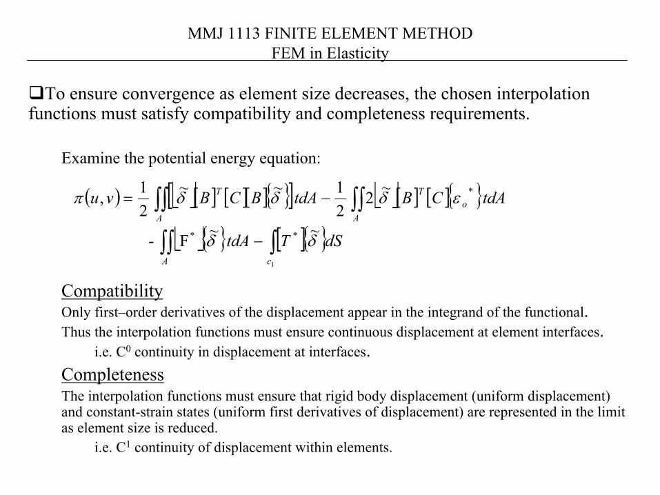
To ensure convergence as element size decreases, the chosen interpolation functions must satisfy compatibility and completeness requirements.
Examine the potential energy equation:
CompatibilityOnly first–order derivatives of the displacement appear in the integrand of the functional.Thus the interpolation functions must ensure continuous displacement at element interfaces.
i.e. C0 continuity in displacement at interfaces.CompletenessThe interpolation functions must ensure that rigid body displacement (uniform displacement) and constant-strain states (uniform first derivatives of displacement) are represented in the limit as element size is reduced.
i.e. C1 continuity of displacement within elements.
( ) [ ] [ ][ ] [ ] [ ] [ ]
[ ] dSTtdA
tdACBtdABCBvu
cA
oT
AA
T
δδ
εδδδπ
~ ~F-
~221 ~~
21,
1
**
*
∫∫∫
∫∫∫∫−
−=
MMJ 1113 FINITE ELEMENT METHODFEM in Elasticity
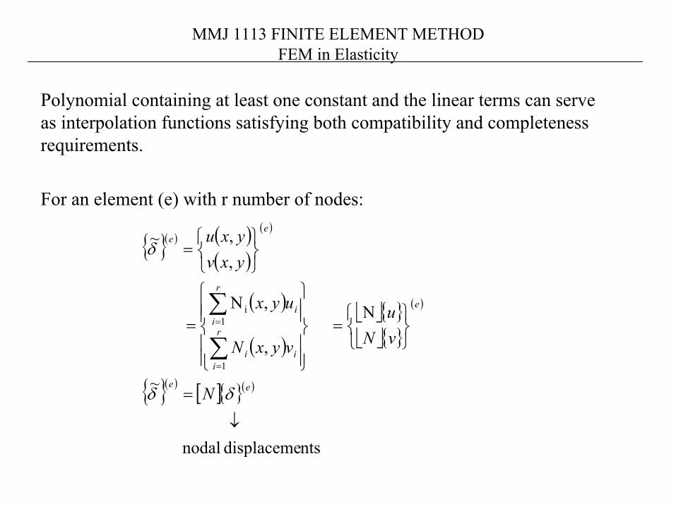
Polynomial containing at least one constant and the linear terms can serve as interpolation functions satisfying both compatibility and completeness requirements.
For an element (e) with r number of nodes:
( ) ( )( )
( )
( )
( )
( )
( ) [ ] ( )
ntsdisplaceme nodal
~
N
,
,N
,,~
1
1i
↓
=
=
=
=
∑
∑
=
=
ee
e
r
iii
r
ii
ee
N
vNu
vyxN
uyx
yxvyxu
δδ
δ

MMJ 1113 FINITE ELEMENT METHODFEM in Elasticity
Minimum Potential Energy Principle
A variational principle that hold throughout the system.Potential Energy = strain energy – work by external force
Strain energy of linear elastic body
Initial strain terms
( ) ( ) ( )wvuWwvuUwvu ,,,,,, −=Π
[ ]
[ ] [ ][ ] dv~ BC~21
dv 21
dv 21
T δδ
εε
σε
B∫∫∫
∫∫∫
∫∫∫
Ω
Ω
Ω
=
=
=
C
U
[ ]
[ ] [ ] dv C~221
dv 221U
0T
0o
εδ
εε
B∫∫∫
∫∫∫
Ω
Ω
=
= C

MMJ 1113 FINITE ELEMENT METHODFEM in Elasticity
Work done by external force
∫∫+∫∫∫= Ω 1
~~21
S dSTdVFW δδ
Body Force Traction
ZYXF = zyx TTTT =
MMJ 1113 FINITE ELEMENT METHODFEM in Elasticity
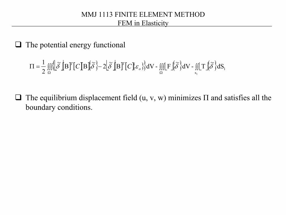
The potential energy functional
The equilibrium displacement field (u, v, w) minimizes П and satisfies all the boundary conditions.
[ ] [ ][ ] [ ] [ ] 1s
dS ~T-dV ~F-dV ~2~~21
1
δδεδδδ ∫∫∫∫∫∫∫∫ Β−ΒΒ=ΠΩΩ
oTT CC

MMJ 1113 FINITE ELEMENT METHODFEM in Elasticity
Theory of Minimum Potential Energy
The displacement field (u , v) which satisfies the equilibrium, and the conditions at the boundary surface is the one that minimizes the potential energy.
( ) ( )( )
( )( )( ) ( )
0,
0,,
11
1
=∑∂Π∂
+∑∂Π∂
=Π
=∑ Π=Π
==
Μ
=
i
r
i i
e
i
r
i i
ee
e
e
vv
uu
vu
vuvu
δδδ
δδvariation
( ) ( )r1,2,.....,i ; 0 ==
∂∂
=∂∂
i
e
i
e
vuππ
Since δui , δvi are independent variations and not necessarily zero, thus

MMJ 1113 FINITE ELEMENT METHODFEM in Elasticity
Look at typical node q of the element, we have
The form of this force-displacement relation for node q is
Additional load vector, if preset, can be added to the resultant external load vector Fq.Example: initial force vector due to initial strains from non-uniform temperature.
( )
( )
[ ] ( )
( )
[ ]( )[ ] ( ) ( ) ( )
( )
( ) ( ) ( ) ( )
( )
0**
0
1
=Ν−Ν−ΒΒ
=
∂∂∂∂
∫∫∫∫∫eee
e
s
eq
eqq
eeq
Aq
eeqep
e
A
Tq
q
eq
e
dSTdApdAtC
v
u
δ
π
π
[ ] elementboundary for -loading surface todue vector force nodal F
vectorforcebody nodal
T
q
=
=
=+=
qB
qqT
qB
qqp
F
FFFk δ
[ ] ( )
( )
[ ]( ) [ ] ( ) ( ) ( )eeepo
e
A
Tq dAtC
e
e *ε∫∫ Β

MMJ 1113 FINITE ELEMENT METHODFEM in Elasticity
Plane stress versus plane strain

MMJ 1113 FINITE ELEMENT METHODFEM in Elasticity
Plane stress condition - small displacement
( )
( )
( )332211332211
332211
332211
21
21
21
ucucucvbvbvbyu
xv
vcvcvcyv
ubububxu
xy
y
x
+++++∆
=∂∂
+∂∂
=
++∆
=∂∂
=
++∆
=∂∂
=
λ
ε
ε
∆=
=
3
3
2
2
1
1
332211
321
321
21
vuvuvu
bcbcbcccc
bbb
xy
y
x
γεε
ε
[ ] δε Β=
000
000
12
3
u1u2
u3
v2
v3
v1
y
x

MMJ 1113 FINITE ELEMENT METHODFEM in Elasticity
[ ] εσ
γεε
νν
ν
ντσσ
C
xy
y
x
xy
y
x
=
−−Ε
=
2100
0101
1 2
Plane stress conditionHomogeneous and isotropic solids
Stress-strain relations
( ) xyxy
yxy
yxx
γν
τ
εν
εν
νσ
εν
νεν
σ
+Ε
=
−Ε
+−Ε
=
−Ε
+−Ε
=
12
11
11
22
22
[ ] ( )( )
lyrespective ratio, sPoisson' and modulus sYoung' are and E where22100
0101
211
conditionstrain PlaneFor
ν
γεε
ννν
νν
νν
−−
−
−+Ε
=
xy
y
x
C

MMJ 1113 FINITE ELEMENT METHODFEM in Elasticity
Example:For a plane stress case, and a typical node, i
If the thickness of the element is uniform (t(e) constant)
If the thickness of the element varies, estimate
Using table 5.2 (text book)
[ ] [ ]( )( )[ ]( )[ ]( ) ( ) ( ) 1,2,3ji,
eA== ∫∫ eeeeeT
i
ij dAtBCBk
( ) ( ) ( ) ( )332211 NtNtNtt eeee ++≈
( )( )
( ) ( ) ∆=∫∫ .ee
A
e tdAte
( )( )
( ) ( ) ( ) ( )( )eeee
A
e tttdAte 3213
++∆
=∫∫
( )( )
( )eA
e
ii
i
i
ii
ii dAtbcc
b
bccbE
e∫∫
−
−∆
= 00
2100
0101
014
122 ν
νν
ν 0
MMJ 1113 FINITE ELEMENT METHODFEM in Elasticity
( )
( ) ( )
( )
∆
=
= ∫∫
*
*e
ee*
*
A
3t
dA te
i
i
i
ii
iB
YX
YXNF
dS *
*
1
= ∫yi
xi
ci
iT T
TNF
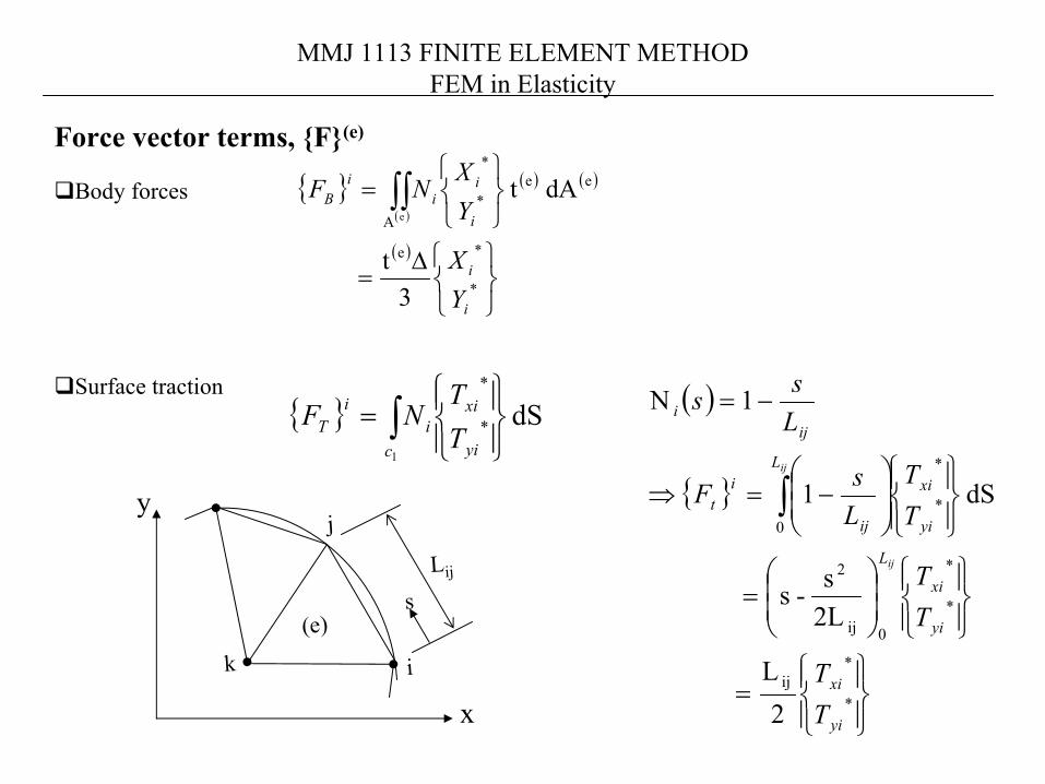
Force vector terms, F(e)
Body forces
Surface traction
k(e)
j
i
Lij
s
y
x
( )
=
=
−=⇒
−=Ν
∫
*
*ij
*
*
0ij
2
*
*
0
2L
2Ls-s
dS 1
1
yi
xi
yi
xi
L
yi
xiL
ij
it
iji
TT
TT
TT
LsF
Lss
ij
ij

MMJ 1113 FINITE ELEMENT METHODFEM in Elasticity
Arrangement of termsdof at each node : 2No. of nodes for each element: rElement matrix : Force-displacement equations: [ ]( ) ( ) ( )eee Fk =δ
[ ]( )
[ ] [ ] [ ][ ] [ ] [ ]
[ ] [ ] [ ]
[ ] [ ] [ ]
=
rrrr
qrqq
r
r
e
kkk
kkk
kkkkkk
k
....................
....................
....
....
21
21
22221
11211
( )
( )
=
=
=
r
qe
r
r
r
e
F
F
FF
vu
vuvu
.....
....F , ........
2
1
2
2
1
1
2
1
δ
δδ
δdiscrete nodal disp.
[k](e)

MMJ 1113 FINITE ELEMENT METHODFEM in Elasticity
Equivalent Nodal Force Vector
STEPS:
Calculate the total load acting on each element surface due to applied distributed loading.Split the total load proportionally to each of the node along the element edge.Sum the load vector at each nodeResolve the resultant nodal force into the desired (x-,y-) component.
MMJ 1113 FINITE ELEMENT METHODFEM in Elasticity
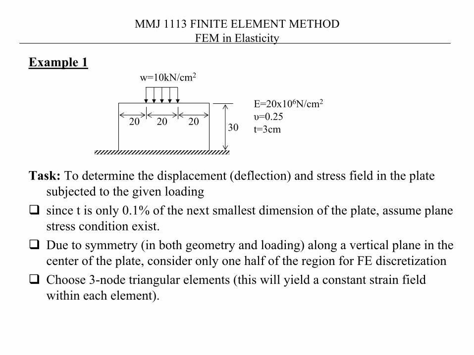
Example 1
Task: To determine the displacement (deflection) and stress field in the plate subjected to the given loadingsince t is only 0.1% of the next smallest dimension of the plate, assume plane stress condition exist.Due to symmetry (in both geometry and loading) along a vertical plane in the center of the plate, consider only one half of the region for FE discretizationChoose 3-node triangular elements (this will yield a constant strain field within each element).
3020 20 20
w=10kN/cm2
E=20x106N/cm2
υ=0.25t=3cm

MMJ 1113 FINITE ELEMENT METHODFEM in Elasticity
Boundary Conditions

MMJ 1113 FINITE ELEMENT METHODFEM in Elasticity
Continuum discretization
3-node triangular elementsTotal of 18 elements and
16 nodes.

MMJ 1113 FINITE ELEMENT METHODFEM in Elasticity
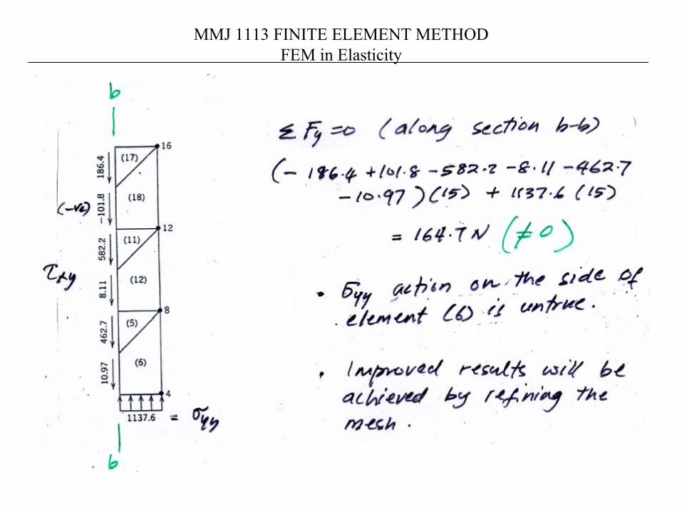
Result
Both tensile and compressive stresses occurs because plate in bending
Stresses are compressive in y-direction

MMJ 1113 FINITE ELEMENT METHODFEM in Elasticity

MMJ 1113 FINITE ELEMENT METHODFEM in Elasticity
MMJ 1113 FINITE ELEMENT METHODFEM in Elasticity

MMJ 1113 FINITE ELEMENT METHODFEM in Elasticity
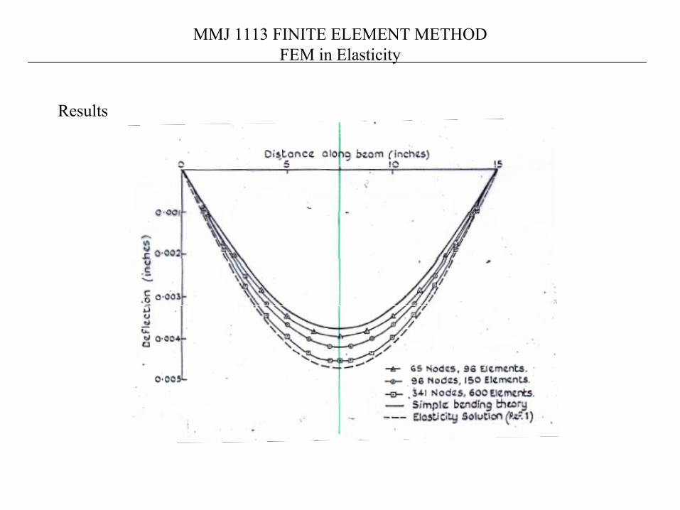
Example 2
Simply-supported beam
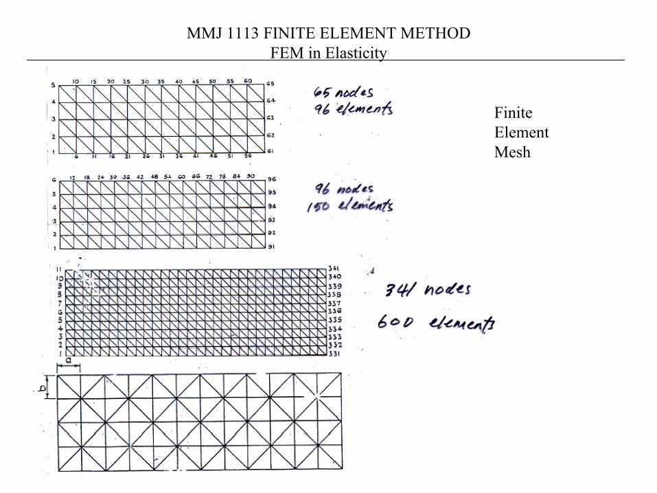
MMJ 1113 FINITE ELEMENT METHODFEM in Elasticity
Finite Element Mesh
MMJ 1113 FINITE ELEMENT METHODFEM in Elasticity
Results