~MMISSION OF THE EUROPEAN COMMUNITIES:·aei.pitt.edu/48017/1/A9756.pdfproposal for a spe~l directive...
37
., '\ •' ' OF THE EUROPEAN COMMUNITIES:· OOM(74) 966 final ? Brussels,· 4:;JU};J 1974 on the approxima.tiqn of the laws of the Member States relating to seamless aluminium alloy gas oylinders (submitted to the Oounoil by the Commission) OOM(74) 966 final
Transcript of ~MMISSION OF THE EUROPEAN COMMUNITIES:·aei.pitt.edu/48017/1/A9756.pdfproposal for a spe~l directive...

.,
'\ •' '
~MMISSION OF THE EUROPEAN COMMUNITIES:·
OOM(74) 966 final ? Brussels,· 4:;JU};J 1974
on the approxima.tiqn of the laws of the Member States relating to seamless aluminium alloy gas oylinders
(submitted to the Oounoil by the Commission)
OOM(74) 966 final
collsvs
Text Box
collsvs
Text Box
collsvs
Text Box
collsvs
Text Box

• ••
collsvs
Text Box

•• ,.
·'
11
..
PROPOSAL FOTI A COUIWIL DIREari"'J:!: 01-T TEE
.APPROXIIVLATION OF THE LA¥iS OF THE ~.IJDi..BER
STATES RELA.TI:!'TG TO SEAiVlLESS ALUIHNIUi'1
AIJLOY GAS CYLINDERS
collsvs
Text Box
collsvs
Text Box

- 1-
I. Introduction
On -the 5·th January 1973, the Commission forwarded to the Council the proposal.
for a eeneral directive concerning appro.J::ination of the laws of the r[amber
Sta;i;es relating to oonmon provisions for pressure vessels and the methods for in~
.:_-1specting them together with the first special directlve on unweldecl steel gas cy-
linders.
tiithin the framework of ha.monisation of ·&he various classes of me,ss-produced
pressure. vessels and wi·th a. viet-r to eliminating the many barriers that there
are to f';reedom of movement owing to the diversity of the legisJ.ative require
ments, administrative and atatu·torj governin[$ design and inspect ·~.on~ in force
in ·~he I:Iember States of the Community, the Commission has, a.ocori:I:;.;:dy1 pre
pared the proposal for a : ... eli recti ve relating to welded unalloyed' stoel gas
cylinders.
This is the third proposal for a special direct and concerns lig'h.t t'J.loy
cylinders. It is similar to the _lines of the proposal of the cirsctive rela}Jteel
til1g to unwoldedfga.s cylinders but is bei:ng expanded to take into col'lsideration
teclmioal aspects and safety factors peculiar to this type of gas c:;rlinder.
As against the use of steel, the use of a.luminitun alloys for the· production of
cylinders is of comparatively recent origin. Given the increasing c;.rowth in
the demand for light alloy cylinders, principally because· of their li~1tness
characteristics and smooth appearance, it is absolutely essential to extend this
proposal for a spe~l directive Which will allow the free circulation of cylin
ders produced from light alloys1 between all l.~ember States.
Ind.eecl1 the different leg'lisltt··.ve provisions a.t the present time in e~istenoe
within the rJiecber States are as result, particularly in the light of experience
acquired that the production of the various alloys are not the same; is a very
sorious restriction of trade.
.;.
collsvs
Text Box

•
--2--
It is therefore necessa.rr.r to dJ."aw up a list of al'Uhlinium alloys admissi l:>le
fol" the mo.nufacture of cylinders as ~Tell as to specify the inspectio11 and
tests to be carried out to meet safety requirements; the co~osive __ behaviour
of cer-~ain alloys particularly to be subjected -~o a special examination.
The employraent of alloys, o-therwise of a lesser commercial importance, having
a tensile strength greater tha.n 500 N/mm2 is not a.lloued to avoid the risk of
cracl: propagation on the stress-resistant cylinder casing.
In orclor not to hamper _teclmical progress, tho Direc·t;ive also maltes Pl"Ovision
for the use of alloys other ·bha.n those pl'escl"i l:>ed, provided that they pass an
intercrystalline corrosion-resis"taJ.lCe test simulating the likely effects of
weather ~let3J." the sea •
.li.s 't-Tith steel gas cylinders, this proposal for a Directive provides for
ncptional" harmonization and applies only to empty cylinders.
2.-:~ Remarks on the :proposal fo.r a. Directi~
., . I;n viet.Y of the analogy t-;hich exists, this proposal for a directive follows the
plan adopted for the Directives on steel gas cylinders. The articles define in
particular:
- tlle sc.ope of application of the Directive;
- the cylinder which may be placed in free circulation and the means of
enmtring such circulation;
- the capacity and pre~SUJ;'e· values of the oylinder determining the illspection ,.
procedures to which it will be subjected.
After defining the alloys approved for oyl~n~er production and giving the broad
lines of the construction rules and processes, Annex I specifies the methods of
carrying .sut the tests a.nd the criteria of acceptance for the cylinders tested.
Thepro_cec.:ures for EEC approval and verification and the requirements for marking
cylinders are then laid down.
Annex II defines the intercrystalline corrosion resistance test to be tnldergone
by other than approved alloys in order to be used in the production of cylinders.
•/o

- 3-
Anno:::es III and TV give forms of certificates of EEC approval and verification.
3. Consultation with circles concerned
With a view to the preparation of the present proposal for a L.irective, a very
detaile~ examination of the different national regulations will first be
carrieJ out. Conclusions drawn from the work of the principal standardisation
and controlling bodies will be utilised to a great extent. Already, at the pre
parat O!'"'J stage of the \-t0!-1: 1 on the spot contacts are made: frequently with consumer
associations, controlling bodies, as well as professional circles. This proce
dure enables the Commission's services to prepare a homogenious draft clirective
which fonns the subject matter for detailed discussions at the principal mee
tings of the Commission's working group of experts, to which consumer associa
tions, controlling and stan1a~is~tion bodies and the European association of
Manufacturers are invited.
4• Consultation of the European Parliament and the Economic and Social Co;nmi ttee.
Pursuant to Article 100(2) of the Treaty, the opinions of thesetwo bodies are
required. Implementation of the proposal provisions would, in the cnso of cer
tain Member States, necessitate amendments to their legislation.
•
•

•
LIST OF 1fl-IE PRINt;IPAL LEGISLATIO!B IN FOHC::: nr IJ.'HE MENIJ3ER STATES
RELATING TO SE.AliLESS ALUMINIUM ALLOY Gli.S CYLINDERS
]}ELGIUH
FRANCE :
General Regulation for work protection (R.G.P T.) :
Kingdom Orders of 11th Februar,y 1946 and 27th September 1947
(Articles 349 to 363).
Regulation for mobile containers and for compressGd cas filling
eq~ipment (Druckgasverordnung) of 20th June 1968.
a) 0rclcr for nobile containers designed for holding C0Llf-:''3Ssed
gas, liquified or dissolved, n° 338 of 11th Dece~~er 1935
and the following amendments
n° 75 of the 19th r~arch, 1959,
n° 73 of the 21st ~'larch 1961,
n° 345 of the 27th SGptember 1963;
b) Instruction n° 17/1972 relating to labelling and periodical
tests.
a) Amended legislation of 28th 0ctober 19,B;
b) Amendment Order of 18th Januai"J 1943;
c) Amendnent Order of 23rd July 1943;
d) Order of 12th November 1962
...

ITALY -~-
IPLELAND
/
- 2-
a) R,D.L. (Royal Order-·in...Council) n° 1331 of 9th July 1926;
(Establishment of the National Association for the Control
of combustion);
b) R.D. (Royal Decree) n° 824 of 12th !.~ay 1927 (Approval of
legislation for the enforcem+mt of Hoyal Order-in-council
n° 1331 of 9th July 1926);
c) D.M, (Ministerial Order) of 20th Augt1st 1933;
d) R.D. n° 2421 of 11th December 1933; .,
e) D.M. of 1st August 1935;
f) D.M. of 27th Oetooer 1969.
Common Law and particularly the "Rylands v Fletcher"
Statute.
LtDCilll.ffiOURQ :
Grand Duchy Order of 24th October 1938.
UNITED KINGDO~~ :
Gas Cylinder Conveyance Legislation 1931, as amended in 1947 and
1939, and certain Exemption Orders.
Home Office Specifications HOAL 1, 2, 3 and 4·
•
collsvs
Text Box

PilOPOS.AIJ R'"t A C.'OUNCIL UIRE~r:'V'E ON Tiffi APPRC'''1111 .. TIC3 J? TI.LE LlF.'i OF 1l'rlE
j_,)EJ:J3}!.;R ~TA11'ES RELATTI G TO 5ti.:JJ.l\1LESS .ALmt:IliTm. ... 1\.LI OY CAJ CYLHf..JER:;;
THE COUliCIL OF 'l'HE EfJROPE.AN COl~VltJl.TITIES,
having regc.rd to the Tren.ty establishing the European Economic Community,
nnd in particulur Article 100 thereof;.
having regGrd to the propos~l from the Commission;
having regard to the Opinion of the b.,urope;an Pnr.liament;
having regard to the Opinion of the Economic nnd Socinl Comn:i ttee;
1iherec.s in the r.1embcr States the coridruction <:Jlld method::: of control of gas
cylinders o..re subject to mnnclo:t ory provisions ,,rhich differ from one Member
St:::.te to another cmd consequently hindnr trade in such cyJ inders? where<1s
it is therefore necesso~y to epproximcte these provisions;
IJherens the Council Directive of •· ••••••••••••••••••• on the approximntion
of the laws of the Member states relating.to common provisions on pressure
vessels ~d to the methods of control of these vessels lays dolin in parti
culo..r the procedures of EEC approval nnd verification for these vessels;
whereo..s, in accordance with that virep~ive, the technical requirements to
be satisfied by EEC type seamless aluminium alloy gas cylinders of 0.2 to
150 litres capacity should be 1:-:.id down, so that these cylinders can be
freely put into circuln.tion, ruarketed nnd used, after they·havc undergone
the proposed controls and have been given the proposed marks ~ symbols;

1 ... ,., .. ,.,.,...., ...
-2-
It~ ADOPTED THIS DIRECTIVE:
Afticle 1
1., 'lhis Directive applies to the ~tress-resistant shells of refillable
seamless al~nium allot ga.s cylinders • (iII eo f formed from' a. $ingle
piece), of a. capacity of o:2 to 150 iitres incluaive and:··~a.:Jigned to ~ cor.;~ain compressed, liquefied or dissolved gases, the effective pressure
of which is grea.ter than 1 bar gauge at a temperature .of 15°Co These
seamless gas cylinders are hereinafter termed "oylinderL9".,
2o The provision of this Directive shall not apply to:
- cylinders manufactured from an aluminium alloy with a tensi~! e. stl'ength
greater tha.n 500 N/mm2; ..
- cylinders l-lhich have been ma.nufaotUl"ed by a method involving the
addition of metal during the process of sealing the bottom end.
Article 2
Cylinders which conform to the requirements laid down in the Annex to
this Directive shall be EEC-type oylinderso
Article 3
No Me~~er State may, for reasons connected with constructions or controls,
refuse, prohibit or restrict the placing on the market and entry into
appropriat-e service •011. LTIX--·~yp_o ·cy.li:nt~:e\r-01 bolftl"'~"'lg~.~llC BEt ··!l.pP·!'OVa.l synbol
n.."'lcl.. "'f:rc~ ·Elie ~ . .ti1sp~ar..illn .un.r~::, 'proV1±ti:sd. t~:1fl;~ the p:oovisione. of· Article 4 ro .. e complied with. ·
· h-tiole 4
EKe-type cylinders shall be subje~t toJ
(a) EEC·apprmval when their ~draulio test pressure is not greater ~han
225 bars and if their oapaoity is not less than Oo2 litresand not
more than 1 litre;
(b) EEC aproval a.nd ElllC inspection
(1) when their hydraulic test preasure is not greatel· than 225 bars
a.nd if their oapa.c i ty is more than 1 litre and not more than
150 litres;
•
collsvs
Text Box

•
--3
(2) lihen their hydraulic ·test ·pressm·e· is greater than 225 bars,
irrespective of their capacity.
1. Member Statear..shall put into force the laws, regulations and
administrative provisions needed in order· to comply with this Directive
within eighteen months' of its notification and shall fortwith inform the
Commission thereof.
2. Member States shall ensure that the te~·::'~ of the mai"'l provisions
of national law which they adopt in the field covered by this JJirective
are communicated to the Commission.
Article 6 ___ ...._ ...
This Directive is addressed to the Member States.

q
ANNEX I
1. TEHMS .f..ND SYMBOLS USED IN THIS ANNEX
Yield stress
The tern "yield stress" I:Jeans the conventional yield stress (RpO• 2) i.o. the VQlue of the stress ( ar ) which gives rise to a non-proportional elongation to 0.2 % of the gauge length of the test-piece.
1.2. The synbols used in this annex have the following meanings:
Ph= relative lzydr~ulic test pressure (design pressure), in' bars;
Pr =relative cylinderburstingpressure mensured in the bursting test, in bars;
Re = minimum value of the yield stress (Rp 0.2) guaranteed by the cylinder manufacturer, in Njmm2;
a
= Dinimun tensile stre~gth mGnufacturer in N/mL~;
= ninimum thickness of the part of the cylinder, in
guaranteed by the cylinder
wall of the cylindrical mm;
D = maximun outsine diameter of the cylinder, in no; Rt = actual tensile strength, in N/nn2 ;
d = diru.:eter of the former for the bend test.
2, TECHNIC.t',L HEQUIREIV!ZNTS
2.1. Materials
2.1.1. The materials used for the nenufacture of the cylinders shall be alUI:Jiniun alloys which, after the proposed he~t treatnent, are sufficiently resistant to atmospheric corrosion.
•
collsvs
Text Box
collsvs
Text Box
I
!
" - 2-·.
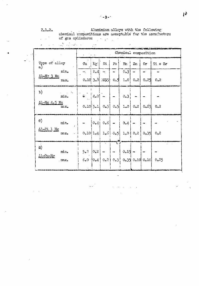
2..1.2. " . Aluminium alloys with the following chemical ·compositions are acceptu.ble· for tlle mrufactn.ro of gro;s cylinders.-:
' ' . ........... 11 ., =
Type of alloy a)
min.
mx.
b) min.·
Ak:,Mg 4. 5 Mn :rrax.
6) r.ri.n.
nnx.
~) min.
Al-Cu -1.1.g-. max.
I 1
;
• ., .. 1 a
Ch~~oal composition
Cu .\ ~ig l:i ' Fef1 . I1n i Zn Cr
'2 -i ·-- . • ·~. 1 .4·. -. - o.3 - -
o.1d 3.8 ::0~5 · o. _1
1.o o.2l 0.2~ { 1 I ! I 1
- I o.fr-_--:-_-·------..... -1
I
Ti + Zr
0.2
I I
i . ~ !' I .... i 4.o -i : 0,1015·11 o.s J ! I
0.25 0.2 0.2 0.5 I
1.0
li l ! I :1
i I o.4 o.6 - 1 0.4 - -
~ I I 0.10! 1.-4 l.u I .o.5j1.0 0.21 0.35
1, -~ ! J I I t :
...,. ' V I I ,. i .. --------+-------1 I I 1 i \J j i 1
1
5.2 1 o~2 1
- - o.1d- ~-i I ., I 6.o
1o.4
1 o.2 0.3~ o.3~ o.1 o.1o
~ . . ! ! t . .1 •• l I J
i I'
I I
0.2
0.25
collsvs
Text Box
collsvs
Text Box

.....
- :l -
For the interpretation of ·~he· results of the chenical . .. analysis of these alloys, referenc_e shall be made to page 4 of the IS·O ·recommendation R209-1971, page 4.
. . ' 2.1.3. Any other aluminiun alloy may be used for the nanufac~ure
· of gas cylinders provided that it ·first passes the at'rlospheric corrosion resistance tests described in annex II
' . to this Directive or, tailing this, complies with a speci-fication laid down by the Comnittee·for Adaption to Technical· Progress refe:r:red tp in.AJ;"ticle .. 19. .. of the .. O.ouno.il Directive of •••••••.••••••••••••••••• on the approxinatio~ of the laws of the Menber States relating to coumon provisions on pressure vessels and to the methods o£ control of these vessels.
........... ...... ·.
2.1.4. The cylinder m:mufacturer shall obtain and provide. cast analysis certificates for the aluminiUD alloys supplied for the nanufacture of thei.cylinders.
2.1.5. The inspection authority· shall···have the· opportunity of making indepen~ent analyses. These analyses shall be carried out either on specinens of the alloy taken ·.~t the time of casting such as those supplied by the alloy manufactures to the cylinder manufacturer or on the
~ - ... ~ ' . finished cylinders.
2.2. Heat and Mechanical Treatnent~
The manufacturer shall state the type of oanufacturc: cold working, type of heat treatnent (temperature nnd duration) and type of cooling.
2.3. Calculation of the Parts under Pressure
2.3.1. The thickness of the cylinder walls shall not at any point be less than that calculated for the cylindrical part by
the fornula :
a =
. The value of R
8 shown in the forLJ.ula shall in_no ·case -be-:: _
greater than 0,85 Rr:t whatever the type of alloy·used.:
•
collsvs
Text Box
collsvs
Text Box
collsvs
Text Box
collsvs
Text Box
collsvs
Text Box
collsvs
Text Box

2.3.2. The ninimun wall thicknesG shall not in any cqse be
less than 1.5, 2 and 3 D.."l respectively for cylinder
dianetcrs of 50 m1 or less, greater than 50 and less than
• 150 I!l.I!l, and 150 nn or nore.
2.3.3. The thickness end the shape of tho botton and the top
end shall be such as to sA.tisfy the r0quirements of the
tests :provided for in iteu 3.2 (bursting test) and 3.3 (pressure cycling test) of this 1~ex.
2. 3 .4. In orG.er to obtain a sc;tisfactory stress fl.istribution,
the thickness of the cylinci.er walls she.ll increase
:progressively in the tr::msition :po.rt situated between
the cylindrical :part and the end; the wall shall be free
tron defects.
2.4.1. Each cylinder shall be exar:.incd for thic~mess and for
extern&l and internal suTfece defects·:
- the wall thickness shall not at eny :point be loss
th::m the.t specified on the dr3.wing;
- the interno.l and e:rterno.l surface of the cylinder
shall be free frvm defects ·which would adversely
affect the safe use of the cylinder.
2.4.2. The out·-of-roundness of the cylinclrice.l shell sh:1.ll be
lic.ited to euch a value that the difference bet~veen the
naxirxuu ::mcl mininun outside dian3ters in the sar:e cross
section is not nore than 2 % of the average of these
dia:.:1eters.
2.4.3. \7hen a footring is :provided, it shall be sufficiently
strong and TJ.ade of a naterial co:::1:patible vd th thnt of
the cylincer. The shape should preferably be cylindrical
D.Ild shall give the cylinG.er sufficient ste.bili ty. The
footring shall not allow we.ter to accunulate or :perni t
ingrees of w::tter between the footring e.nd. the cylinder.

3. TESTS
3.1. Mechanical Tests
3.1 o) 1. Gene raJ regu:l..rene~
.b.ll the I:lechanical tests for checking the properties ·of the alloy of gas cylinders shG.ll be c'll'rieG. out on test pieces taken froD the finished cylinders.
3.1.2. ~es of tests and evaluation of test resul~
Every test cylinder shall undergo one tensile test·in a longitudinal direction and four band tests in a circunferential direction.
3.1.2.1. Tensile test
3.1.2~1.1. The tensile test shall be carried out on a_test specimen of the type shown in Fig• 1 of this Annex with a gauge length L
0 = 5,65 V~ F being the right
cross-section of the test piece. The two faces of the test piece representing the inside and outside surfaces of the cylinder shall not be nachined.
3.1.2clo2. The·el~ngation in percent shall not be less than:
- 12% !ur the ~lays referfed to in (n), (b) and . (c) v! the table in ito~ 261.2 und for the allo7s .. · . . ,subject to the requireJ...ents in 2.1.3;
\ l
- 10 % for the alleys referred to in (d) of the table in itew 2.1.2.
3.1.2.2. Bend test
3.1.2.2.1. The bend test shall be carried out on speci~ens obtained by cutting into two equal parts a ring of width 3a; in no case may the width of the test piece be ~ess than 25 nn.
•
collsvs
Text Box

•
- 6 -
Each strip may be mac~ined only on the enges.
3cl.2.2~2· The bend test shall be carried out by moans of a for~1er of diameter d and two cylinders separated by a distance of d + 3a. During the test, the inside face of the ring shall be placed against the former.
3.1.2 .. 2e3• The test piece shall remqin uncr3.cked wi1en bunt ir.~.wqrds
around the forrc'er until the interior edges are separated by a distar:.ce not greater than t:1e diameter of the former~
3.1.2.2.4. The ratio (n) betvveen the dio.meter of t:w fOI'rler ru1d the thickness of the test piece shall conforl"1. to the values given in the following table
. . • .
Actual tensile strength Rt in N/B..m2
. . . • . . •
Value of n • • . . ~-----·----------------------~·-------------~
: . . up to 330 inclusive:
above 330 to 400 inclusive: above 400 to 500 inclusive:
Test conditions - -·-------
6 7 8
• . • . . .
The bursting test under hydraulic pressure shall be carried out in two successive stQges by neans of an apparatus such that the pressure in the cylinder increases regularly until the cylinder bursts and that the curve of the pressure v~iation with tine is recorded.
During the first stage, the rate of pressure increase ur~il the point of which plastic defor~ation begins shall be Rbout 1 bar/s.
From that point, (second st.'3.ge) the pumping rate shall be increased to four ti~es that of the first stage and kopt constant until the cylinder bursts.

/ \~
- 7..-
Performance of test ----·- IIU; - .............. _ ........ ..-......
The bursting test under hydraulic pressure shall afford:
- an examination of the pressure/tine curve, in order to deternine the pressure at which plastic deformation of the cylinder comaences, the bursting pressu.re and the deformation of the cylinder during the test;
- an examination of the fracture and the shape of its edges.
Test accept~nce conditions
The pressure corresponding to the initiation of pl~stic deforJ~ation shull not be less th.s.n four-thirds of the hydraulic test pressure.
The neasured bursting pressure (Pr) shall not be less than five-thirds of the test pressure (Ph).
The bursting test shall not cause any fragoentation of the cylinder.
The main fracture shall not sho~ any signs of brittleness i.e., the edges of the fracture sh~ll not be radial but shall be sloped in relation to a diauetrical plane and shall show signs of strict~on throughvut their thiclmess.
The fracture shall not reveal a ch~racterized defect in the netal.
The fracture shall begin and develop in the cylindrical part and shall not extend into either end of the cylinder.
Data wh:\ch me_y helun the inter:pretati~p. of the test
The neasure~ent of t~e voluwe of water used from the start of the pressure build-up to the monent of bursting, this gives an indication as to the voluoetric expansion of the cylinder.
•

- 8-
The oeasurement of. t4e increas.e in the ¥irc\u_,.fr~rence
of the cylinder in the A..rea of the fracture.
Pr.essure Cyc_1ing Tes~
The pressure cycling test shell be (HJ.r:ried out on two cylinders, which are guaranteed by the nanufecturer to be reasonably rerresentative of the minir~un thickness valuas e·nvisaged in the design, using a non-corresive fluid.
The test shall be carried out by subjecting the cylinder to successive reversals of hydra-;1:-'_ic :pressure between the initial or residual. :;~~essure end the pressure known as the test pressu1 ... B ..
The test parameters shall satisfy either one or the other of the following conditions, the choice being left to tho Member State~
1) - total number cycles • 80tj000 • test pressure • 2/3 Ph + residual pressure •
- frequency • 15 cycles/minute •
2) -.total number cycles • 15.000 4l
- test pressure • Ph + residual pressure • - frequency e 5 cycles/oinute •
The residual pressure (the pressure at the end of the cylinder decompression phase) she.ll not exceed 5 ~6 of the value of the test pressure"
The temperature neasured on the outside wall of the cylinder shall not exceed 5000 during the testo
No fracture shall occur during the test.
H;ydraulic test
The value of the hydraulic pressure test shall be equal to the design pressure (Ph).

\-1
3.4.4.
- 9 -
The w~ter pressure in the cylinder shall increase reG~larly until t~e test pressure is reached.
The cylinder shall reuain under the test pressure for a tine sufficiently long to denonstrate that the pressure shows no tendency to fall and thnt leaktightness has been achieved.
~ cylinder which does not satisfy these test requirenents· shall be rejected.
4. EEC .. ..I'FR OV .i-~L
4 .. 1. The applicant for approvrtl shall suboit the docunentation necess~ry for the verification prescribed below, together with a nmJber not exceeding eight prototype cylinders, fully representative of future production, which nay be necessary for carrying out the tests prescribed bolow, an1l any additional information required by the lJienber State.
4.2. In the course of the EEC n.pprov::ll process, the Member State shall :
- verify that the calculRtions provided for in iten 2.3 are correct;
- verify that the conditions laid do1...m in i ter.s 2~1 and 2.2 ~re satisfied;
- perforn on the cylinders subnitted as prototypes: -the tests provided for in item 3.1.2. except
in respect of the n~~ber of tensile tests, three of these tests beinc required; tbe test provided for in item 3.2, on two cylinders; the test provided for in iten 3.3, on two cylinders, except whore only the length paranoter of tl~e cylinde:r differs and is situated in the range of lengths of the types of cylincers which have already been approved;
- issue the EEC approval certificate conforning to the ooo.el in Annex III to this Directive.
5. EEC INSP:SCTI ON
5.1. For the ~urp~se of EEC inspection the cylinder

.. 10-
manufacturer shall ~ ----·-··......_ ........... _....__........,.
make available to the in.spection authority:
the EEC approval certificate; - the. analysis certificates of the aluminium allo.ys
supplied for the manufacture of the cylinders and when the cylinder is manufactured with the alloy referred to in (d) of the table in item 2e1.2 the results of intercrys·talline corrosion tests carried ou.t according to one of the n:.ethods desgribed in section 1 in Annex II to this Directive, on 'test pieces taken fro.o one cylinder of eash tempering charge;
- the means of identifying the a1 ur:rl.nium alloy Q3.st from. which each cylin·ier is nanufactured; the docUnents necessary to certify that the cylinders submitted for EEC inspeetion h&':re undergone the saLle heat treatnent as those sni.-;'2-:i.tted for the approval procedure;
- the list of cylinders stating the nnnbers and the narks provided for in item 6~
In ~e EEC inepectiqg
The control QUthority shall :
- ascertain that approval has been obtained and that the cylinders conforn to this approval;
- check the docuoents which give the data concerning the naterials; ascertain whether the technical requirements set out in Section 2 have been net, and verify in particular, by an external nnd internal visual examination of a sanple nunber of between 5 a..."'ld 10 % of the cylinders in each batch whether the construction and the exanination carried out by the Danu.facturer in accordance with item 2.4.1. are sati~factor,y;
- be present e.t the tests pres_cribed in i·tems 3~'~1 and 3.2 and check the way··they are carried out; ascertain whether the information sup~lied by the manufacturer in tho list in iten 5.1&1 (fifth indent) is correct. Between 5 ru1 1 0 ~6 of tho cylinders in each batch shall be subjected to this check;
- issue the EEC inspection certificate conforning to the model in Annex IV .. to this Directive ..
... ll -
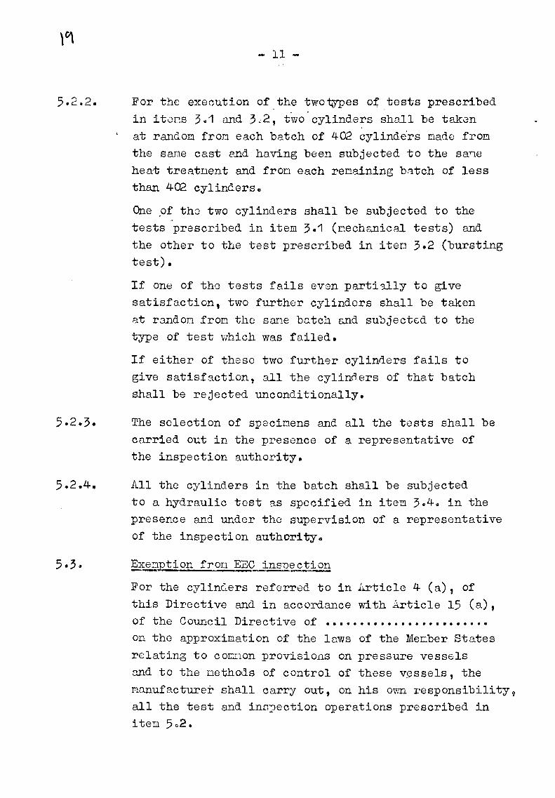
For the execution of,the two~es o~.tests prescribed in itons 3~1 and 3~2, two-cylinders shall be takGn at random fron each batch of 402 cylinde'rs made from the same cast and having been subjected to the sane heat treatnent and fron each renaining batch of less than 402 cylinders.
One ,of tho two cylinders shall be subjected to the ,,
tests prescribed in item 3.1 (nechanical tests) and the other to the test prescribed in iten 3.2 (bursting test).
If one of tho tests fails even parti3lly to give satisfaction, two further cylinders shall be taken at r:mdoB from the sane bc.tch and subjected to the type of test which was failed.
If either of these two further cylinders fails to give satisfaction, all the cylinders of that batch shall be rejected unconditionally.
The selection of specinens and all the tests shall be carried out in the presence of a representative of the inspection authority.
All the cylinders in the batch shall be subjected to a hydraulic test as specified in ite~ 3$4G in the presence and under the supervision of a representative of the inspection authority.
5.3 ~ §2cenytion fron E:2:C ins12~ction
For the cylinG.ers referr0d to in l..rticle 4 (a) , of this Directive and in accordance with Article 15 (a), of the Council Directive of • • • • • • • • • • • • • • • • • • • • • • • • on the approximation of the laws of the Me~ber States
relating to c 0r::1:10n provisions on pressure vessels and to the methods of control of these v~ssels, the nanufacturer shall carry out, on his OVI~ responsibility 9
all the test and ins?ection operations prescribed in item 5o2.

- 12 -
The :oanufacturer shall pr-ovide the inspecti~n autrortty with n.ll the dccunents 2..nC::. t:1e test and cvntl"'Ol rE..pO:.t.'ts e
The presence of a representative of the inspection authority (cf. ite:os 5~2.3.and 5.2.4. of this ltrrllex) shall not be requirsd.
6. M.f:u-q}(ING
6.1. 1Y.hen all the presc. ib8d chE..cks have been carried out by the inspection euthori ty, and providing tho.t the results are satisfactory, the inspection e.uthority shall issue a certificate statinc; the checks which he.ve be :::n carried out.
6~2. The narkings shall be grouped toGet~er ~d none nay be stanped on the stress-resistctnt shell of the cylinder.
6.3. it synbol shall be st~i:lpGd on th.::; net.'l.l of the top end of each cylincer or on an irlentific:ltion p:.:1tc, if any, of a r::tinirw.:1 thicknecs of 3 r-;n; tr ... e synbol
6.4.
referred to iL itcn 5o3 of ;illnex I to thu Council Directive of • • • . • . • • • • • • • • • • • • . • • • • • on the epproxin-ation of th0 lavlS of th.::; lVTGL1ber States -relating to comrJon provisions on pressure vessels and to the nethods of testing these vessels shall be used for the cylinders referred to in Article 4 (a) of this Directive, and the synbol of EEC type ap:provo.l S referred to in Ar...ncx I iten 5.1., follo\;ed by the synbol of EEC inspection 11 8 11 referred to in Annex II iten 3.1.1.1. (a) of the above-r::tentioned Directive shall be used for the cylinders referred to in 1.~-rticle 4 (b) of t~.1is Directive,
These syv~ols shall be followed by the following ne.rldngs :
Markip~§ relatin~to the construction
!n_rc~~.£.Lc:.f tbe ,:tete.l
A nunber indic~ting the value of Re in N/om2 , on which the calculation was based.

y\
6.4.3.
6.4.4.
in respect of t~_El._}1;:zdraulic ~
The V'llue of the tPst pressure in bars in figures l~rger than the others and above then, the date (nonth and year) of the first hydrGulic test.
!£ respe~t of the tlPe of_cylinder
Below the figure relating to the test pressure, the weight of the cylino.er in kg, without the valve and tap , and the nininun capa~ity in litres guaranteed by the cylir.der manufacturer.
The weight end the capQcity shall be expressed to three significant figures, the third one being fixed "by rounding dovv:n" for the capacity and "rounding up" for the weight.
~n respect of the origi~
The nanufacturer's nark and the serial number.
£ e 2?0
04/72 ,~\ n 5-(. /_ ....
10,4/40,5
6c851

--:----.,...---~-------"· ·--\
- 14 -
. I
' ' .._ ...
(:l
0 Q>
•r: . .. r:.·, ·-!-' u. ()
.p
(ll ,..., •r-i . (( -~;
Gl E•
.. r-1
• 1:10
•n c.,.
'
I. I I I
--·-
,
0 .j
.. ' . 'i
;•
... I
! .. r-· I Q;
'l:' ~--·1- e! ~l
L t ·~I '
(() I ~~>
_ __: i ~
l; t()
d)
11
~ ....J
I ,r..!
·I +>
.
ct ;. ll
t ~ !G (• r· ['
0 •r-' .r: +' ri ,....; r: " ' .. c:
·' ..
t
collsvs
Text Box
collsvs
Text Box

...
JJ.NNEX II -------TESTS TO EVALUJ~TE SENSITI""VITY .TO INTZRCRYST.:~LLIIf~ CCPJ.-"0.3IO .. ;
The @ethod described below consists of inmersing the specinens taken fron the cylinder under test in two different corrosive solutions at the same tine, exaoining the~ after a specified etching tine for any signs of intercrystalline corros~on and deteroining the type and intensity of such corrosion. The propagation of intercrystalline corrosion is deterrined netallographical~ on polished surfaces cut transversely to the etched surface.
1.1. Saopling
Specinens are taken froo the pointed top; the body end the bottom of the cylinder (Fig~1), sv that the tests ~th solution A defined in 2.1~1~ and solution B defined in 2.1.2. can be carried out on netal from three parts or the cylinder.
A sufficient nunber of speciwens uust be taken to neet the requirelJents set out .in 2.2.1 and 2•2•2•
Each specimen nust be of the general form and the dimensions given in Fig. 2 •.
The f.s.ees a1' a2 a3 a4, b1 b2 b3 b4, a1' a2 b2 b1 ' a4 a3 b3 b4-are all sawn with a band saw and then carefully tri~n.eC. with a fine file. The surf'nc.es a1 a4bib1 and a2 a3 b3 b2 which correspond respectively to the inner and outer faces of the cylinder are left in their original pp~gh state.
1.2. Preparation of surface before corrosive etchins
1.2.1. ~ro~ucts reguir@d
EN03 for analysis, density 1.33 HF for analysis, density 1.14 (at 40 %)
· Deionized water

- 2 .•
1.2.2. !~ethod
In ~ one-li trc pyrex be?J.:er, prepare the following solution : HNO : 63 cn3 HF 3 : 6 cm3 H20 929 cn3
Heat the solution to 95° C
Dip each specimen suspended en an alu....'liniun vd.re for one uinute in this solution.
Then wash in running water followed by deionized w.1.ter.
Immerse the spaci1.:.1en in nitric acid e.s defined in 1 .2 .1.
above for 1 rdnute, at roOD teT'.l.peraturc, to renove any co:9per c.eposit 1-vhich nay h'1ve forced.
Rinse in deicnized wP-ter. I
To prevent oxyd:::.tL:m of specir.1ens, on co1:1pletion of preparution they should be plunged in the corrosion bath intend~d for then (see 2.2 below).
2. FERF ORM.tlWE OF TEST -2.1. Two corrosive solutions arc to be used, one with
57 g/1 sodi~ chloride and 3 g/1 hydrogen peroxide (= solution A), and the other 17ith 30 g/1 sodiun chloride nnd 5 g/1 hydrochloric acid (= sol~tion B).
2.2. prep'"U'e.tion of corrosive solution~
2-2~1. Solution A
2.2.1.1. ?roducts reguir~ NaCl, crystallized, for analysis H2o2 100 - 110 nedicinal volunes KMn04 for analysis H2so4 for nnalysis, density 1.83 Deionized water

..
- 3 -
2.2.1.2. ~itration of_gydro0ep_p££o::i~
Since hydrogen peroxide is not very st!i.ble, i·'c is
essential to titrate it bvfore use. This is done
as follows.
T"lire 10 c::t3 of hydrogen peroxifl.e lllli th o. pipette,
dilute to 1,000 cn3 (in a gauged flas~) with
deionized water, thus obtaining a hydrogen peroxide
solution whicll ~.ill be called C. With a piyette,
plRce in an erleru"leyer flo.sk :
- 10 CLl3 of the hydrogen peroxide solution 0
- about 2 cn.2 of sulphuric ecid, density 1.83.
A solution of pernanganat-:; et 1.859 g/1 i3 t:.seC..
for the titration. The pernanganate itself serves
as en indico..tor.
Thb rec,ction of the per:o.a11genate on the hydrogen
peroxide in a sulphuric :1ec.iu::1 is expressed as :
2 EIVln04_ + 5 H2 o2 + 3 H2 S04 ~ K2 S04 + 2 Mnso4
+ 8H2 0 + 5 02
which gives the equivalence : 316g KNm04 ~ 170 g H2 o2
Therefore 1 g of pure hydrogen peroxide re?.cts on
1.859 g of pernanganate; h&Dce the use of a 1.859 g/1
solution of per~~gan\te, which, vol~~e for volune,
s~turates 1 3/l of hydrogen ~eroxide~
Since the r~drogen peroxide was previously diluted
100 tiw.es, the 10 cr.:J.3 of the test S&lple :cepresent
0., 1 cD3 of the original hydrogen peroxi.de,
By rmltiplying by 10 the nUIJber of cubi.c centineters
of peruane;cmate solution used fo::::- the titrc.tion,
the titre T of the j_ni tial hyd.rogcn peroxide in
g/1 is obt2inEd.

\
- 4-
2~2.1 .. 4. Preparatl.Q!L2.L._the solution
Method for 10 1 :
Dissolve 570 g of sodiun chloride in deionized water to obtain a total volume of about 9 1. add the quantity of hyd.rcgen pGrcxic1e calculated below. Mix end then na~_ce up the volume to 10 1
with deionized uater.
~v~ati~of hydrogen peroxide volune to be
pl~~~ in ~ution
~u~tity of pure hydrogen peroxide required: 30g.
If the hydrogen peroxide contains T graLDes of H2o2 per litre, the volune required, expressed in cubic centinetres, will be :
Solution B
1,000 X 30
T
2.2.2.1. ?roducts regu~~:
NaCl, crystallized, for 8nalysis HCl, pure concentrated" 37·% HOl Deionized w"l.ter
2.2~2.2. Prenaration of the solution
Method for 10 1 :
Dissolve 300 g of sodiu.TJ. chloride and
50 g of HCl (50 g ~ 0.5 %) in 9 1 of Qeionized water, nix well anQ oake up to 10 1.
2.3. Etching conditions
2.3.1. Etchi~g in solution A
The corrosive sclution is placed in a crystallizer (or possibly a large beaker) and this in· its turn is placed in a water bath. The water bath is stirred with a nagnetic stirrer ~d the ter.perature is regulated with a contact thernoueter.

·'
- 5-
The specinen is either suspended in tho corrosive solution by an nlu.::1iniun 1vire or pl~wed in tto solution so th:-<t it rests only on the corners 1 the second wethod being preferable. The etcl.~.ing tine is 6 hours anc'l. t!le termerature fixed l'.t 30 + 1° C.
~ -CITe should be taken to ensure that tho quantity of reagent is at least 10 cn3 per cn2 of specinen surface.
After etching, the speciwen is washed in water, im.::.ersed for abvut 30 seconds in 50 % dilute nitric acid, washed n.grin in weter and dried by coupressed air.
2.3.2. A nunber of speci~ens ern be etche~ at the s~1e tine provided. th&t they .s.re of t.b.e sar:12 typv of r.lloy ancl thqt they P.re not in c(.mtact. c::'he Piniuun quantity of re3.t:;ent per unit of s:peci:wen surface nust, of course,be respected.
2.3.3. Etching in solution B
The corrosive sclution is poureQ into a suitable glass container (e.g. a b-:;aker). The test is cc,rried out at roor1 tGnperature. Wl.J.ile it is inr.-ossible to avoid variations in ro0n tPm.perature <l.uring the test, it is prefer9.ble tu carry out the test in the water bath, the temperature of which is cdjusted to 23°C by a ther..-::~ostat. Etchir..g ti:o3 ia 72 hours.
The spcci:wens ere kept iiTJersed in the corrosive solution in accordc.nco with 2.3.1. After etching, the specinens are very carefully washed w::'Lth deionizecl wrtter and dried by co::-1pressed air free of srease. Care nust be taken to see that the ratio quantity of corrosive so1ution/Epecimen su!:'face in Dl/cn2 is 10 : 1 (sec 2.3olo)o

- 6. ·-
3. PREP AR.e;.TI ON OF SFECII'JISNS FOR EXL1ITNATI ON _._.... ,...,.,.,.._,...._.,...., - -~1~L~,SLuir££ c~stins dishes with, - external diaQeter .. height - wall thickness
e.g., the : 40 f1Iil
: 27 r'Il : 2,5 DD
following Qin8nsions :
l~aldite DCY 230 ) Hardener HY 951 ) or equivo.lent
3.2. Method Eac~ specimen is placed vertically in a casting dish on its face a1 a2 a3 a4. Around it is poured a nixture of o.ralclite DCY 230 e.nd hardener HY 951 in the proportion 9 to 1.
The setting tine is about 24 hours.
A certain a:lOu.."'lt of :r.1.aterial is renoved fron the face a1 a2 a3 a4, preferably by lathe, so that the section a'1 a 1 2 a 1 3 a'4 E:xanined under the Dicroscope cannot show corrosion from the surface a1 a2 a3 a4. The distDnco between the faces a1 a2 a3 a4 end a'1 a'2 a'3 a 14, i.e. the thickness re~oved by the lathe, oust be at least 2 nu (Figs. 2 and 3).
The section for ex~in9.tion is polished r:.echanica.lly with alUBino. first on paper and then on felt.
4. 1~CR0GRJ.J:'HIC EXiJu~INHTION OF SPECIMENS
The ex~.in~tion consists of noting the intensity of intercrystalline corrosion round the entire perinetor of the se0tion. In so doing, account is taken of the properties c·f the netal on the outer r:md inner surface of the cylinder and in the thickness of it.
The section is first ex~nined at low nagnification (e.g., x40), in order to locate the nost corroded areas, and then at a higher nagnificction, usually Rbout x 300, in order to assess the nature and extent of the corrosion.

. ·,
·-. , ...
.·
.·· . . .
·-
•' '
. · .. . .
' '• i.
.. :·
,/ /.
.. : ... ,.. -~·-: ·.: ... ". .. ·•.
. . .I
tl
tl
.·
-... -:·,.~; --··-··
. ..
' ..
,..... ·-~ ... , I • .I I I
I 'f 1-T:......._L_ ~ . .. I·. I
/.: · I 1 ·,I ,_._/ L-r-'
'\-\ \ \
_.\_·-\--\ \ \, \ ~-- ._,
11
----1--- .
..
r-1- i. ~-·--., 1.'. :·.. . ... ··:,
( . I I .: I . ,~ _I __ , . : r-- ·--,.' .. 1 I:· 1;1 • I' . . ,f I ~ •, .I L-- .•.!J I.!:-.:.' .
t
. •'
-- --r· .,-···-. -·-~--; :: ......- -:-·:. ----- ·----·
·····
·.
.. '·
--1, ~·---.----
- ~ - .
._.
--";""'"'.--·. ·•. - ........ .
collsvs
Text Box
collsvs
Text Box
collsvs
Text Box
collsvs
Text Box
collsvs
Text Box
collsvs
Text Box
collsvs
Text Box
collsvs
Text Box
collsvs
Text Box
collsvs
Text Box
collsvs
Text Box
collsvs
Text Box
collsvs
Text Box
collsvs
Text Box
collsvs
Text Box
collsvs
Text Box
collsvs
Text Box
collsvs
Text Box

.·
...
-- .. ·~ •. . :. . . . . . : .. • 4. .. .. # :. !"
., . ..
..
·.·. ... 0 • -.!t ..•• ..:
t..
,,
.. , .
I'
_ora\dih~,
I
T~IOKNE"')S OF TE~ OYLPIDlli
.·
. ..
~PEC~N OF THE ,cYLINDER...:._· - · ......;;..:._ ----
.•··
·.
fJ9_· 3_
, . •
,. : .
collsvs
Text Box
collsvs
Text Box
collsvs
Text Box
collsvs
Text Box
collsvs
Text Box
collsvs
Text Box
collsvs
Text Box
collsvs
Text Box
collsvs
Text Box
collsvs
Text Box
collsvs
Text Box
collsvs
Text Box
collsvs
Text Box

1
- 7-
It is verified thA.t intercrystalline corro~:.-:i ::m is c:u·:;:c,r--
ficial, i.ee, that its depth does not oxc~ed threG grRins perpendicularly to the face exPDined~ However, it is perr.itted to exceed these vo.lues locally provi,.d8d the.t they cccur in not JJ.ore t:tan four fields of exru:J.ination at x300 n3..gnification ..
II. T~STS TO EV.L~iliU.L,_TE REDUCTION IN WaLL THICKliESS _;,s A RE8UI·T
OF C O?.R CSI ON BY liffil.,.THER
The exanination of corrosion beh3..viour ~ust b3 cowpleted by c: test on finished cylinders and/or spoci:-.1ens fro:-1. finis:1ed cylinders to expose then to the nest corrcsi ve WOfl.ther likely to occur durinr:; thv utiliz.:J.tion of the cylinders$
This test should pernit the evaluation of ::ony reduction in W'l.ll c;ylinders, during the cylinder's c::verage life o
The vnlue so obtained Dust not exceed 0.2 ITio
3;
However, Q reduction in thickness exceeding 0.2 ~ is &llowed prcvi:ied that an equivalent extra thickness is taksn into consideration when tl1e wo.ll thiclmess of the cylinc1.er resistant shell is C3..lcul::'l.ted.
collsvs
Text Box

1 .. N NE. X III
EEO i.PPl-?.OV.:..r~ CER~IFIC.::.TE -------·
Inspection authority: Application of Council Directive ~o of
• • • • • • • • • • • • • • • ............. Date: Designation of cylinners: EEC approval code N° ••••••••••e
Capacity: ....................... .
Manufacturer's nrne and e..ddress:
The undersigned hereby declRres that he has checked that the ver1ficQtions, tests a~d inspections, laid down in Point 4.2 of .tUl!le::::: I tc the Council Directive N° ••••••••••••••••••••• of ••••••••••••••••••• •'• ••••• h3.Ve been carried out succesfully.
cylin~ers of the accepted design C-ar: ot subject to EEC C-ar n inspection
G2ner3.l renarks: the nrawing T,vhich was the subject of approval i·s annexed hereto.
Signed and certified this •••••••.••• day of ••••••••••••••.•••• at • . • • . • • • • .. • • ... • .. • • • • • . • • . • • • • . •
• • • • • • • • • • • • • • • • • • • • • • • • • • (signature and capacity)
l
collsvs
Text Box

-'
ANNEX IV _ _,__ ___ _ EEC INS7ECTI ON CEETIFIC--'l1E
Inspection authority:
Date~ Designation of cylinders:
i:..pplic'ltion of Council Directive N° ••. o • • • • • • • • • • • • of •..•..•.• EEC ap~roval code go ••••••••••• EEC incpection cc1e N° ••••••••• Capucity: ·~···················· Production batch N° ••••••••••••
Name and ~ddress of the n~ufacturer:
The lmdersigned hereby declares th~t he has checked that t~e verifications, tests and inspectioj_1s pr0sc::.:'ibed in .iLr.w.'1e1: I, Point 5.2, of the Council Directive N° •• ' ••••••••••••• ., ••••• of • ~ ••••••••••••••..••.•• have been C'l.rrie<1_ out successfulJy.
Snecial r~n~ks:
General rerJ::::_rks:
Signed ancl certifieG. this • • • • • • • • • . • duy of ................. . at ................ ~ .... e
• • • • • Q • • • • • • • e • • o o • o e • o • ~ • • • • c • •
(signature anQ c~p::::_city)
collsvs
Text Box

collsvs
Text Box