MMA-273336 v3 - Home - Microwave Technology Operating Temperature ºC -40 to +85 MMA-273336 27-33GHz...
8
MMA-273336 27-33GHz 4W MMIC Power Amplifier Data Sheet MicroWave Technology, Inc. an IXYS Company, 4268 Solar Way, Fremont, CA 94538 510-651-6700 FAX 510-952-4000 WEB www.mwtinc.com Data sheet is subject to change without notice. All rights reserved © ECCN: 3A001.b.2.c Please visit MwT website www.mwtinc.com for information on other MwT MMIC products. Page 1 of 8, Updated May 2018 Features: • Frequency Range: 27 – 33 GHz • P1dB: +36 dBm • IM3 Level: -38 dBc @Po=20dBm/tone • Gain: 22 dB • Vdd = 6V • Idsq = 1500 to 2800mA • Input and Output Fully Matched to 50 Ω Applications: • P2P Radio • V-sat Description: The MMIC is a high power amplifier MMIC die designed for use in transmitters that operate at frequencies between 27GHz and 33GHz. In the operational frequency band, it provides 36dBm of output power (P-1dB) and 22dB of small-signal gain. Absolute Maximum Ratings: (Ta= 25 °C)* *Operation of this device above any one of these parameters may cause permanent damage. SYMBOL PARAMETERS UNITS Min. Max. Vds Drain-Source Voltage V 6.5 Vg Gate-Source Voltage V -2.1 0 Ig First Gate Current mA -17 17 Pd Power Dissipation W 24 Pin max RF Input Power dBm 20 Die size: 3.15x2.8x0.05 mm 124x110x2 mil Channel Temperature ºC +160 ºC -55 to +150 Tch Tstg Tmax Storage Temperature Max. Assembly Temp (20 sec max) ºC +250 Toper Operating Temperature ºC -40 to +85
Transcript of MMA-273336 v3 - Home - Microwave Technology Operating Temperature ºC -40 to +85 MMA-273336 27-33GHz...

MMA-273336 27-33GHz 4W MMIC Power Amplifier
Data Sheet
MicroWave Technology, Inc. an IXYS Company, 4268 Solar Way, Fremont, CA 94538 510-651-6700 FAX 510-952-4000 WEB www.mwtinc.com
Data sheet is subject to change without notice. All rights reserved © ECCN: 3A001.b.2.c Please visit MwT website www.mwtinc.com for information on other MwT MMIC products.
Page 1 of 8, Updated May 2018
Features: • Frequency Range: 27 – 33 GHz• P1dB: +36 dBm• IM3 Level: -38 dBc @Po=20dBm/tone• Gain: 22 dB• Vdd = 6V• Idsq = 1500 to 2800mA• Input and Output Fully Matched to 50 Ω
Applications: • P2P Radio• V-sat
Description: The MMIC is a high power amplifier MMIC die designed for use in transmitters that operate at frequencies between 27GHz and 33GHz. In the operational frequency band, it provides 36dBm of output power (P-1dB) and 22dB of small-signal gain.
Absolute Maximum Ratings: (Ta= 25 °C)*
*Operation of this device above any one of these parameters may cause permanent damage.
SYMBOL PARAMETERS UNITS Min. Max. Vds Drain-Source Voltage V 6.5
Vg Gate-Source Voltage V -2.1 0
Ig First Gate Current mA -17 17
Pd Power Dissipation W 24
Pin max RF Input Power dBm 20
Die size: 3.15x2.8x0.05 mm 124x110x2 mil
Channel Temperature ºC +160
ºC -55 to +150
Tch
Tstg
Tmax
Storage Temperature
Max. Assembly Temp (20 sec max) ºC +250
Toper Operating Temperature ºC -40 to +85

MMA-273336 27-33GHz 4W MMIC Power Amplifier
Data Sheet
MicroWave Technology, Inc. an IXYS Company, 4268 Solar Way, Fremont, CA 94538 510-651-6700 FAX 510-952-4000 WEB www.mwtinc.com
Data sheet is subject to change without notice. All rights reserved ©Please visit MwT website www.mwtinc.com for information on other MwT MMIC
products. Page 2 of 8, Updated May 2018
Electrical Specifications: Vds=6V, Vgs=-0.85V, Idsq=2200mA, Ta=25 °C Z0=50 ohm
Parameter Units Typical Data
Frequency Range GHz 27-33Gain (Typ / Min) dB 22 / 20Gain Flatness (Typ / Max) +/-dB 3 / 4Input RL(Typ/Max) dB 10/8Output RL(Typ/Max) dB 10/8 Output P1dB(Typ/Min) dBm 35.5/35Output P3dB(Typ/Min) dBm 36.5/36IM3 Level (1) dBc -36Thermal Resistance ⁰C/W 3.8Operating Current at P1dB(Typ / Max)
mA 2500 / 3000
(1) Output IP3 is measured with two tones at output power of 20 dBm/tone separated by 20 MHz.

MMA-273336 27-33GHz 4W MMIC Power Amplifier
Data Sheet
Typical RF Performance: Vds=6V, Vgsq=-0.85V, Idsq=2200mA, Z0=50 ohm, Ta=25 ºC
20 22 24 26 28 30 32 34 36 38 40Frequency (GHz)
-20
-15
-10
-5
0
5
10
15
20
25
30
S11,
S21
, and
S22
(dB
)
DB(|S(1,1)|)MEAS
DB(|S(2,1)|)MEAS
DB(|S(2,2)|)MEAS
S11, S21, and S22 vs. Frequency
P-1 and P-3 vs. Frequency
IM3 level [dBc] vs. Output power/tone [dBm]
Po(dBm), and Ids(mA) vs. Pin(dBm)
MicroWave Technology, Inc. an IXYS Company, 4268 Solar Way, Fremont, CA 94538 510-651-6700 FAX 510-952-4000 WEB www.mwtinc.com
Data sheet is subject to change without notice. All rights reserved ©Please visit MwT website www.mwtinc.com for information on other MwT MMIC
products. Page 3 of 8, Updated May 2018
MMA-273336 27-33GHz 4W MMIC Power Amplifier
Data Sheet
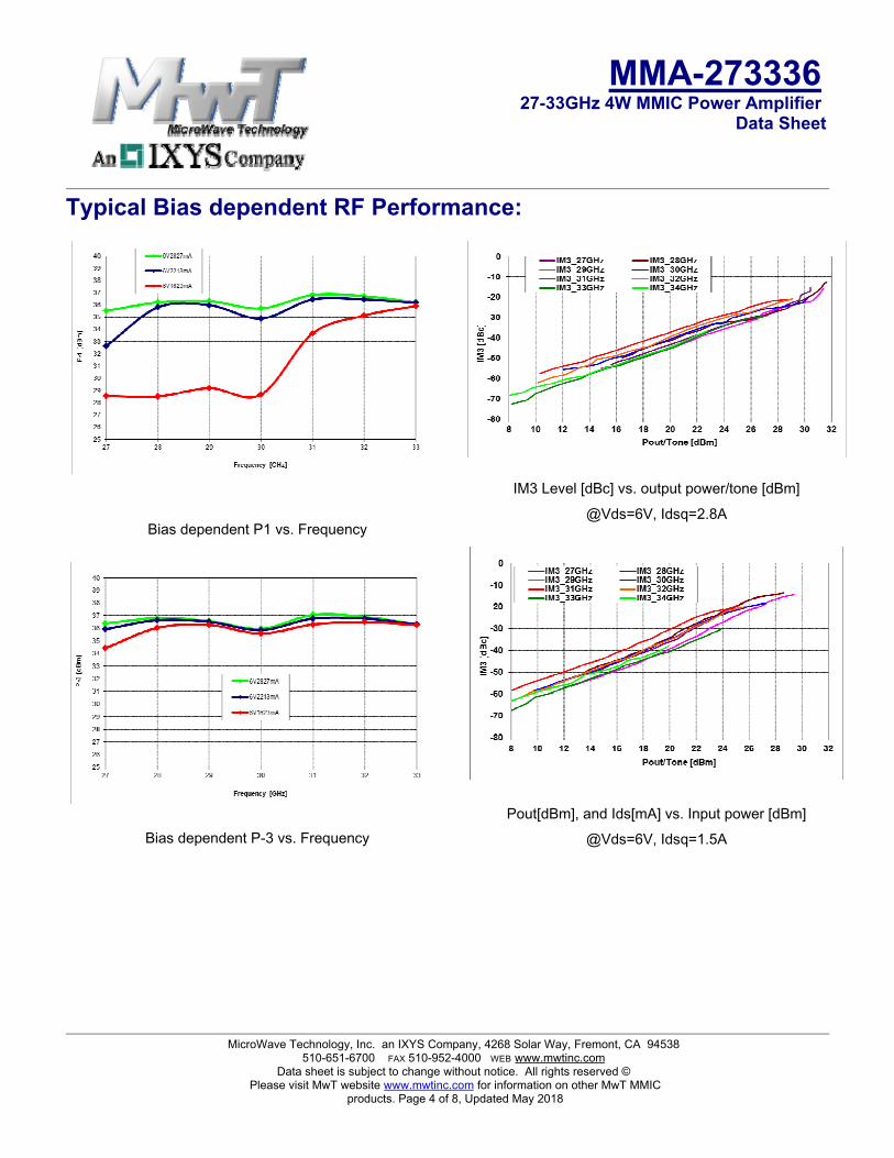
Typical Bias dependent RF Performance:
Bias dependent P1 vs. Frequency
Bias dependent P-3 vs. Frequency
IM3 Level [dBc] vs. output power/tone [dBm] @Vds=6V, Idsq=2.8A
Pout[dBm], and Ids[mA] vs. Input power [dBm] @Vds=6V, Idsq=1.5A
MicroWave Technology, Inc. an IXYS Company, 4268 Solar Way, Fremont, CA 94538 510-651-6700 FAX 510-952-4000 WEB www.mwtinc.com
Data sheet is subject to change without notice. All rights reserved ©Please visit MwT website www.mwtinc.com for information on other MwT MMIC
products. Page 4 of 8, Updated May 2018

MMA-273336 27-33GHz 4W MMIC Power Amplifier
Data Sheet
Applications The MMA273336 MMIC power amplifier is designed for use as a power stage amplifier in microwave transmitters. It is ideally suited for 27 to 33GHz band V-sat transmitter applications requiring excellent saturated output power performance. This amplifier is provided as a bare die format in a Gel-pak.
Biasing and Operation The recommended bias conditions for best performance for the MMA273336 are VDD = 6.0V, Idsq = 2200mA. Performance improvements are possible depending on applications. The drain bias voltage range is 5 to 6V and the quiescent drain current biasing range is 1500mA to 2800mA. A single DC gate supply connected to Vg will bias all the amplifier stages. Muting can be accomplished by setting Vg to the pinch-off voltage (Vp=-2V). The gate voltage (Vg) should be applied prior to the drain voltages (Vd1, Vd2, Vd3) during power up and removed after the drain voltages during power down. The RF input and output ports are DC decoupled internally. Typical DC supply connection with bi-passing capacitors for the MMA273336 is shown in following pages.
Assembly Techniques GaAs MMICs are ESD sensitive. ESD preventive measures must be employed in all aspects of storage, handling, and assembly. MMIC ESD precautions, handling considerations, die attach and bonding methods are critical factors in successful GaAs MMIC performance and reliability.
MicroWave Technology, Inc. an IXYS Company, 4268 Solar Way, Fremont, CA 94538 510-651-6700 FAX 510-952-4000 WEB www.mwtinc.com
Data sheet is subject to change without notice. All rights reserved ©Please visit MwT website www.mwtinc.com for information on other MwT MMIC
products. Page 5 of 8, Updated May 2018

MMA-273336 27-33GHz 4W MMIC Power Amplifier
Data Sheet
Mechanical Information:
0
0 111 340 795 1970 2230 3150
1400 1400
28002800
0 135 325 535 728 1970 2230 3150
RF_INRF_OUT
Vd4Vg2
Vg1
Vd1
Vd3
Vd4Vd2
MicroWave Technology, Inc. an IXYS Company, 4268 Solar Way, Fremont, CA 94538 510-651-6700 FAX 510-952-4000 WEB www.mwtinc.com
Data sheet is subject to change without notice. All rights reserved ©Please visit MwT website www.mwtinc.com for information on other MwT MMIC
products. Page 6 of 8, Updated May 2018

MMA-273336 27-33GHz 4W MMIC Power Amplifier
Data Sheet
Application Circuit:
RF IN RF OUT
RF Input
Vd1
Vd4Vg
RF Output
0.01u
10Ω
1uF
0.01u
10Ω
1uF
Vd2
0.01u
10Ω
1uF0.01u
10Ω
1uF
DET_R
Note:Vd4 bonding pads
must be biased from both sides.
RF IN
Vg1 Vd4
Vd1 Vd2 Vd4
RF O
Vd3
10Ω
1uF
0.01u
Vd3 Vd4
1.5K
MicroWave Technology, Inc. an IXYS Company, 4268 Solar Way, Fremont, CA 94538 510-651-6700 FAX 510-952-4000 WEB www.mwtinc.com
Data sheet is subject to change without notice. All rights reserved ©Please visit MwT website www.mwtinc.com for information on other MwT MMIC
products. Page 7 of 8, Updated May 2018

MMA-273336 27-33GHz 4W MMIC Power Amplifier
Data Sheet
Recommended Application Module:
MwT
Vg
Vd1 to
Vd3Vd4
Vd4
RF_IN
RF_OUT
0.01uF
1uF
MicroWave Technology, Inc. an IXYS Company, 4268 Solar Way, Fremont, CA 94538 510-651-6700 FAX 510-952-4000 WEB www.mwtinc.com
Data sheet is subject to change without notice. All rights reserved ©Please visit MwT website www.mwtinc.com for information on other MwT MMIC
products. Page 8 of 8, Updated May 2018