mm-wave telecom and datacom background · telecom and datacom infrastructure market Confidential...
28
mm-wave telecom and datacom background Confidential under NDA 1
Transcript of mm-wave telecom and datacom background · telecom and datacom infrastructure market Confidential...

mm-wavetelecom and datacom
background
Confidential under NDA 1

Sivers IMA 60-80 GHz time line
20132012
E and V-band Backhaul & Fronthaul
2015
V-band Backhaul Handheld spectrum analyzers
E-band
2014 2016
ExampleCustomer products:
Products:
2011
E and V-bandConverters
Gen 0.5
E and V-bandConverters
Gen 1.0
FirstSiGe MMIC
E-band Backhaul
E and V-bandConverters
Gen 2.0
70 Ghz “5G”access
Strictly confidential under NDA 2
E and V-bandchip
Gen 3.0
2017

Smartphones keeps on driving data
Confidential under NDA 3

Mobile infrastructure gets further developed
• Need for speed & low latency• More advanced networks• Lack of spectrum is driving new
technology (mm-wave)• Backhaul need increase• IoT and 5G is coming• Reduce cost need -> C-RAN
Confidential under NDA 4

Growth 2022: Mobile infrastructure LTE and 5G
• +2.7 billion LTE• +0.5 billion 5G
Confidential under NDA 5

How will mm-wave support this growth?
Federal Communications Commission (FCC) in the US open up for mm-wave
• 27.5-28.35GHz• 37-38.6GHz• 38.6-40GHz• 57-71GHz (14 GHz)• 71-76 and 81-86 GHz (10 GHz)
USA market = first moverEarly markets Japan, China and Korea
Confidential under NDA 6

Wi-Fi and Cellular evolution
802.11ad, 802.11ay and 5G
key RF features • mm-wave• Beam steering/
Beam forming• Phased array
antennas
Confidential under NDA 7

Why beam steering/forming
Confidential under NDA 8
• mm-wave has higher free space path loss• Compensated by using phased array and BF• Phased array and BF increased gain• BF increase directivity (even NLOS) • BF reduces interference and crosstalk
Omni-directional
Phased array with BF
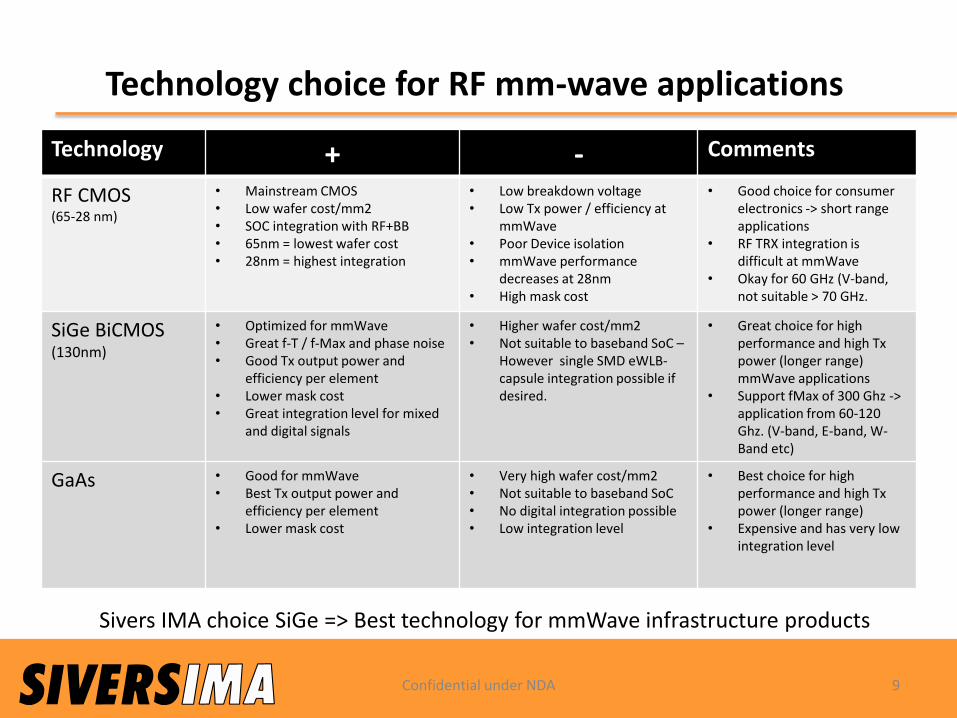
Technology choice for RF mm-wave applications
Technology + - Comments
RF CMOS(65-28 nm)
• Mainstream CMOS• Low wafer cost/mm2 • SOC integration with RF+BB• 65nm = lowest wafer cost• 28nm = highest integration
• Low breakdown voltage• Low Tx power / efficiency at
mmWave• Poor Device isolation• mmWave performance
decreases at 28nm• High mask cost
• Good choice for consumer electronics -> short rangeapplications
• RF TRX integration is difficult at mmWave
• Okay for 60 GHz (V-band, not suitable > 70 GHz.
SiGe BiCMOS(130nm)
• Optimized for mmWave• Great f-T / f-Max and phase noise• Good Tx output power and
efficiency per element• Lower mask cost• Great integration level for mixed
and digital signals
• Higher wafer cost/mm2• Not suitable to baseband SoC –
However single SMD eWLB-capsule integration possible if desired.
• Great choice for high performance and high Txpower (longer range)mmWave applications
• Support fMax of 300 Ghz -> application from 60-120 Ghz. (V-band, E-band, W-Band etc)
GaAs • Good for mmWave• Best Tx output power and
efficiency per element• Lower mask cost
• Very high wafer cost/mm2• Not suitable to baseband SoC• No digital integration possible • Low integration level
• Best choice for high performance and high Txpower (longer range)
• Expensive and has very low integration level
Sivers IMA choice SiGe => Best technology for mmWave infrastructure products
Confidential under NDA 9

mm-wave use cases fortelecom and datacom
infrastructuremarket
Confidential under NDA 10

Confidential under NDA 11
The future is millimeter wave, Sivers IMA is the future!

Macro cell Backhaul Point to Point
• 28, 60-80 GHz backhaul solutions• Cheaper than fiber (low cost and fast installation)• Traditional point to point or 802.11ad/ay
2 GHz bandwidth, 256 QAM and up to 10 Gbps
Confidential under NDA 12
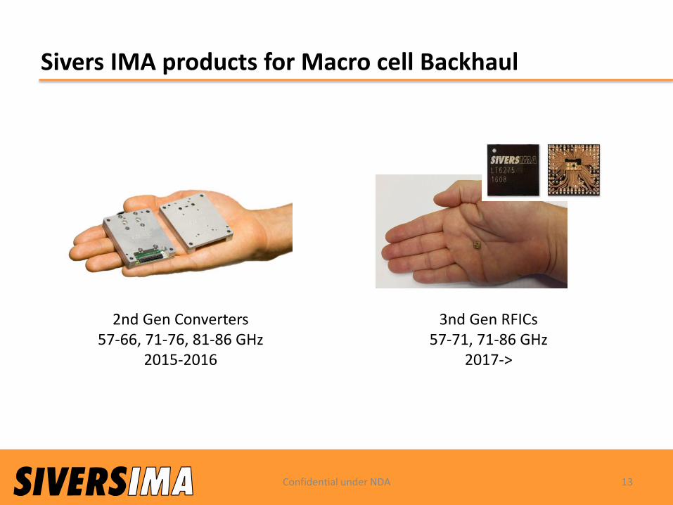
Sivers IMA products for Macro cell Backhaul
2nd Gen Converters57-66, 71-76, 81-86 GHz
2015-2016
3nd Gen RFICs57-71, 71-86 GHz
2017->
Confidential under NDA 13

C-RAN Fronthaul Point to Point
Confidential under NDA 14
• 60-80 GHz fronthaul solutions• Cheaper than fiber (low cost and fast installation)• Low latency • Traditional point to point or 802.11ad/ay• Beam steering and beam forming will be key
0.5-2 GHz bandwidth, up to 10 Gbps

Mesh network - Point to Multipoint
28 GHz, 39, 60GHz solution (WiGig/802.11ad) with: • Easy installation: beam steering and beam forming
3 sectors are needed to cover the full 270° degrees
Point to Multipoint
Confidential under NDA 15

Fixed Wireless broadband access
28 GHz (5G), 39 GHz (5G) or 60GHz (WiGig/802.11ad)
• Easy installation: beam steering and beam forming• Large bandwidth and speed > 1 Gbps• Cheaper than fiber (low cost and fast installation)
Confidential under NDA 16
Google Fiber -> FWA

Outdoor and Indoor: Carrier grade Wi-Fi access point at 60 GHz
• High output power to cover large cell• 60 GHz give high free space path loss –> requires beam steering and beam forming• Support for tri-band required
4 sectors are needed to cover the full 360° azimuth
Confidential under NDA 17

Indoor: High-end Tri-band Wi-Fi access point
Confidential under NDA 18
• High output power to cover longer distance in rooms• 60 GHz give high free space path loss –> requires beam steering and beam forming• Sivers IMA solution only for high-end access points due to cost• Support for tri-band required
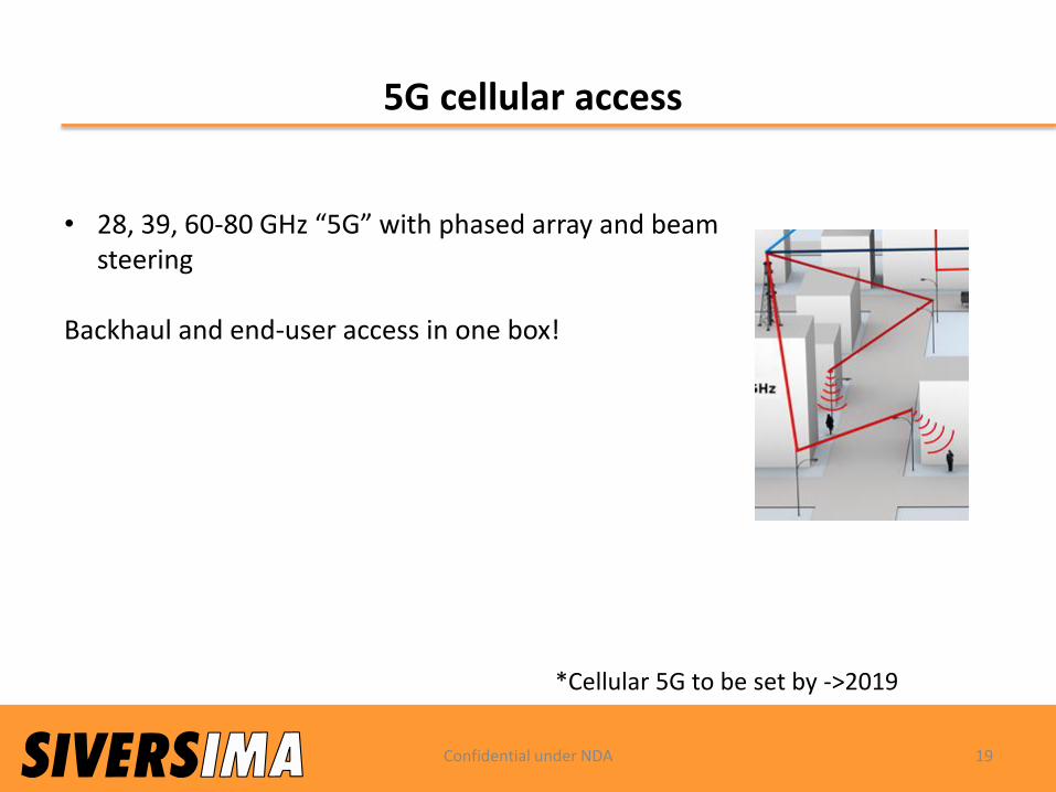
5G cellular access
• 28, 39, 60-80 GHz “5G” with phased array and beam steering
Backhaul and end-user access in one box!
*Cellular 5G to be set by ->2019
Confidential under NDA 19
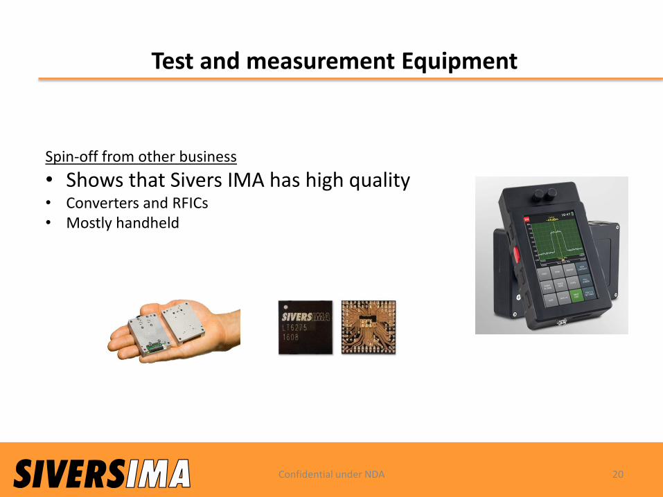
Test and measurement Equipment
Confidential under NDA 20
Spin-off from other business
• Shows that Sivers IMA has high quality• Converters and RFICs• Mostly handheld

PRODUCTS AND PARTNERSHIPS
#mm-waveandphotonics
21

From Concept to mm-Wave converters
Sivers IMA’s value chain
Concept Wafer RFIC/MMIC Sub-System
Thresholds:
• Instruments
• Technology
• Manufacturing
18-24 months!!

Evaluation Board Introduction
Traffic Unit TRU
Power Supply, Surveillance
Modem
BUS DC
Control & Interface Board
Bas
eban
d In
terf
ace
Diplexer
I
Q
I
Q
Strategic partners product area
An
ten
na
Sivers IMA Converters
Sivers IMA Evaluation Kit
Converter Evaluation Board

FC2xxxUp and Downconverters
forE- and V-band

Point to Point mm-waveTRX 1608-LT6275
25
• Support FDD and TDD
• Frequency band: 57 up to 71 GHz
• Modulation schemes: QPSK up to 64QAM
• Speed up to 4.5 Gbps
• Universal analog I/Q base band interface
• IF bandwidth up to 1000MHz
• RF Bandwidth up to 2000 MHz
• Analog RF and IF gain control
• Integrated Voltage Controller Oscillator (VCO)
• Support external local oscillator (LO)
• Digital Interfaces: SPI, GPIO
• Integrated power detection function
• On-chip temperature sensor
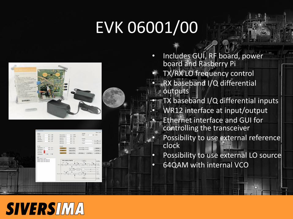
EVK 06001/00
• Includes GUI, RF board, power board and Rasberry Pi
• TX/RX LO frequency control • RX baseband I/Q differential
outputs • TX baseband I/Q differential inputs • WR12 interface at input/output • Ethernet interface and GUI for
controlling the transceiver • Possibility to use external reference
clock • Possibility to use external LO source • 64QAM with internal VCO

27
• Until product is in “General Availability”/Mass Production all market activities and engagements will be controlled and managed from Sivers IMA
• Agreement with Integrated Device Technology (IDT) as reseller in the bundled offering of RFIC and BBIC (full WiGig node)
Focus on telecom/datacom Tier 1 customersIDT resellers will offer bundled offer to the market
• Agreement with RF Module partner that will sell full RF Modules including antennas.
• Decision how to manage RFIC sales to “non-IDT” customers when product is in mass production status
• Opportunity for resellers to explore potential market in industrial applications
E.g Intracompany datacom networksApplicable when in mass production (planned Q2 2018)
WiGig clarification

THANK YOU!
Sivers IMA ABBox 127416429 KistaSweden
Confidential under NDA 28