
MLI 8300 Installation Instructions - Millennium USA, Inc
11
MLI 8300 Installation Instructions Millennium USA Inc, Installation Materials MLI 8300 Page 1 MLI 8300 Under Lipped Manhole Lock Instructions The following is an installation guide for City workers and contractors for the MLI 8300. If installers have any questions please contact us at 713-266-1400 and ask for installation assistance. Also please visit www.millenniumusainc.com for more information on installing the The MLI 8300
Transcript of MLI 8300 Installation Instructions - Millennium USA, Inc

MLI 8300 Installation Instructions
Millennium USA Inc, Installation Materials MLI 8300 Page 1
MLI 8300 Under Lipped Manhole Lock Instructions
The following is an installation guide for City workers and contractors for the MLI 8300. If
installers have any questions please contact us at 713-266-1400 and ask for installation
assistance. Also please visit www.millenniumusainc.com for more information on
installing the The MLI 8300

MLI 8300 Installation Instructions
Millennium USA Inc, Installation Materials MLI 8300 Page 2
Parts listing
A. (2) Main Body Bolts
B. (1) Key
C. (2) Lower Nuts
D. (2) Upper Jam Nuts
E. (2) Lock Washers
F. (2) Rubber Washers
G. (2) Tightening tools
H. (2) Underbody units
O. (2) Nut Stoppers
Tools Listing
I. Crescent Wrench
J. Allen Wrench (3/8”)
K. Socket Wrench (1/4”)
L. Tape Measure
M. Dry Lubricant (Teflon)
N. Allen Wrench (3/16”)

MLI 8300 Installation Instructions
Millennium USA Inc, Installation Materials MLI 8300 Page 3
Step 1 Ensure all materials are present
Step 2
Using a tape measure, measure the distance from the bottom of the inner ring that the manhole rests on to the top of the manhole housing. This measurement will be used in the very next step of the installation process. This distance is usually 2”

MLI 8300 Installation Instructions
Millennium USA Inc, Installation Materials MLI 8300 Page 4
Step 3 Install the 2 main body bolts (A) into the pre-drilled holes on the manhole cover. Using the locking tool (B) tighten the locking screws on top of the bolts to lock both main body bolts into place and keep bolts from falling out during installation. This will allow you to screw on the required nuts. Factory recommendation to spray dry lubricant Teflon (M) on the main body bolt threads to prevent nuts from seizing.
Step 4 Using the measurement from “Step 2” install the jam nut (D) onto main body bolt (A) to the appropriate height from the top of the main body bolt down the thread. In most cases, the jam nut should be placed about 2 inches from the top of the main body bolt (A) down the thread. These nuts can be adjusted once installation is complete to minimize the amount of ‘play’ the manhole may have if the jam nuts (D) are installed too low on the bolt.

MLI 8300 Installation Instructions
Millennium USA Inc, Installation Materials MLI 8300 Page 5
Install the lock washers (E) onto the main bolt body (A)
Install the underbody units (H) onto the main body bolt (A). Please note the cut out on the bottom of the underbody should face downward.
Install the Rubber washers (F) onto the main body bolt (A) to fit inside the cavity of the underbodies (H). The nut, washer, underbody, and rubber washer should all be stacked on top of each other at this point.

MLI 8300 Installation Instructions
Millennium USA Inc, Installation Materials MLI 8300 Page 6
Install the lower nuts (C) onto the main body bolt (A). The lower nuts (C) should be threaded up to fit into the cavity of the underbody (H). The nut should only be tightened to fit into the cavity with a little bit of ‘slop’. The ‘slop’ will allow the unit to bite into the sides of the manhole housing better. Do not over-tighten the lower nuts (C). Attach nut stopper (O) to bottom of each bolt using Allen head cap screw and tighten with 3/16” Allen Wrench (N).

MLI 8300 Installation Instructions
Millennium USA Inc, Installation Materials MLI 8300 Page 7
Step 5
Ensure that the underbodies are facing inward to allow for the manhole cover to fit into the manhole housing, and replace manhole cover back on manhole.
Step 6 To lock manhole cover, remove the locking screws with the unlocking key (B)
Install the tightening tools (G) onto the top of the main body bolts (A) in place of the locking screws. The tightening tools (G) have two parts to them, the slotted hex and the cap screw. Ensure that the slotted hex slot fits over the slot groove found on the top of the main body bolt (A). Once in place install the cap screw and thread it into the main body bolt (A) and tighten with an Allen wrench (J). Only tighten until snug, over tightening will prevent you from easily removing the tightening tool (G) later during the install process.
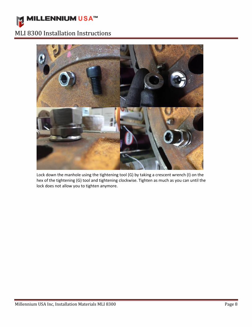
MLI 8300 Installation Instructions
Millennium USA Inc, Installation Materials MLI 8300 Page 8
Lock down the manhole using the tightening tool (G) by taking a crescent wrench (I) on the hex of the tightening (G) tool and tightening clockwise. Tighten as much as you can until the lock does not allow you to tighten anymore.

MLI 8300 Installation Instructions
Millennium USA Inc, Installation Materials MLI 8300 Page 9
Remove the tightening tool by using both the Crescent wrench (I) and Allen wrench (J). Using the Crescent wrench (I) on the hex of the tightening tool (G) by applying force in a tightening (clockwise) manner and using the Allen wrench (J) in a counter clock wise manner simultaneously. This will allow you to retain tension while removing the unlocking tool (G)

MLI 8300 Installation Instructions
Millennium USA Inc, Installation Materials MLI 8300 Page 10
Re-install the locking screws using the key (B) and tighten down using a socket wrench (K).

MLI 8300 Installation Instructions
Millennium USA Inc, Installation Materials MLI 8300 Page 11
Test the manhole locks by trying to pry the manholes out of the manhole housing. If too much ‘play’/ ‘slop’ is present, remove the manhole from the manhole housing and tighten the jam nuts (D) to be threaded higher up the main body bolt (A). When manhole is firmly locked down, remove the locking screws and apply Locktight Blue per manufacturer’s recommendation. (Suggested manufacturer recommendation is to use no more than one drop Locktight Blue (C) on the locking screw before re-installing in areas with excess ground vibrations such as a street with heavy traffic use to lock nut in place)