MLC-based Linac Radiosurgery - AMOS...
44
1 Strategies and Technologies for Cranial Radiosurgery Planning Grace Gwe-Ya Kim, Ph.D. DABR MLC-based Linac Radiosurgery
Transcript of MLC-based Linac Radiosurgery - AMOS...

1
Strategies and Technologies for Cranial Radiosurgery Planning
Grace Gwe-Ya Kim, Ph.D. DABR
MLC-based Linac Radiosurgery

2
Disclosure
• No conflict of interests to disclose.

3
• Introduce the overview of MLC-based
Linac radiosurgery.
• Demonstrate basic treatment
planning techniques for MLC based
radiosurgery
• Discuss metrics for evaluating SRS
treatment plan quality.
Learning Objectives
4
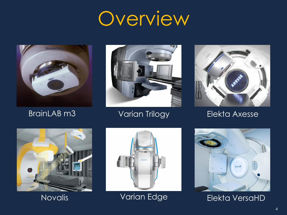
Overview
Varian Trilogy
Novalis Varian Edge
BrainLAB m3 Elekta Axesse
Elekta VersaHD

5
Evolution of technology
Hardware
Software

6
• Better conformity for irregular target
• Improved dose homogeneity inside the
target
• Comparable dose fall-off outside the target
• Less time-consuming treatment planning
• Shorter treatment time
• Linac is not limited for cranial treatment
MLC based Linac SRS

7
What is one advantage of MLC-based
Linac radiosurgery over other machines?
SAM Question 1.
5%
3%
2%
10%
79% 1. Relatively fast treatment delivery
2. Easy to treat heterogeneous tissues
3. Multiple choices of different cone sizes
4. More accurate delivery
5. Easy forward planning

8
What is one advantage of MLC-based
Linac radiosurgery over other machines?
Ref: L Ma et al., Variable dose interplay
effects across radiosurgical apparatus in
treating multiple brain metastases, Int. J
CARS, 20 April 2014
Answer: 1. Relatively fast treatment delivery
9
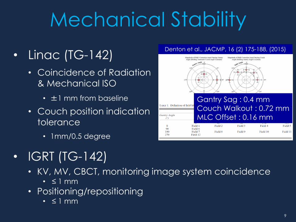
• Linac (TG-142)
• Coincidence of Radiation
& Mechanical ISO
• ±1 mm from baseline
• Couch position indication
tolerance
• 1mm/0.5 degree
Denton et al., JACMP, 16 (2) 175-188, (2015)
Mechanical Stability
Gantry Sag : 0.4 mm
Couch Walkout : 0.72 mm
MLC Offset : 0.16 mm
• IGRT (TG-142) • KV, MV, CBCT, monitoring image system coincidence
• ≤ 1 mm
• Positioning/repositioning • ≤ 1 mm
10
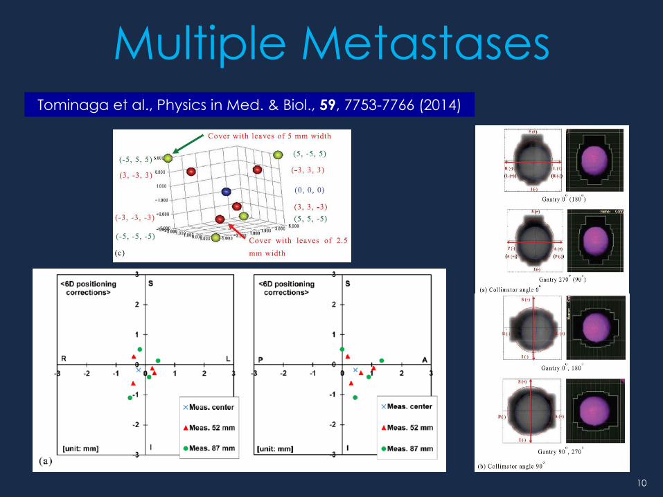
Multiple Metastases Tominaga et al., Physics in Med. & Biol., 59, 7753-7766 (2014)
11
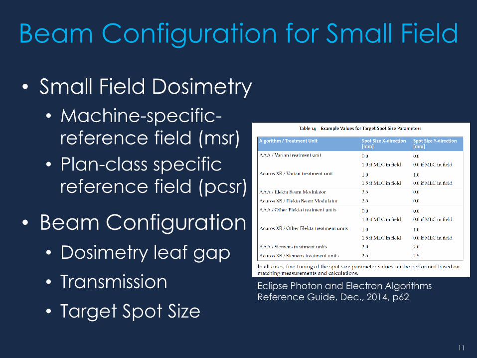
• Small Field Dosimetry
• Machine-specific-
reference field (msr)
• Plan-class specific
reference field (pcsr)
• Beam Configuration
• Dosimetry leaf gap
• Transmission
• Target Spot Size
Beam Configuration for Small Field
Eclipse Photon and Electron Algorithms Reference Guide, Dec., 2014, p62

12
Treatment Planning Imaging
Registration
Contouring
Prescription
Setting up the fields
Optimization
Plan Evaluation
13
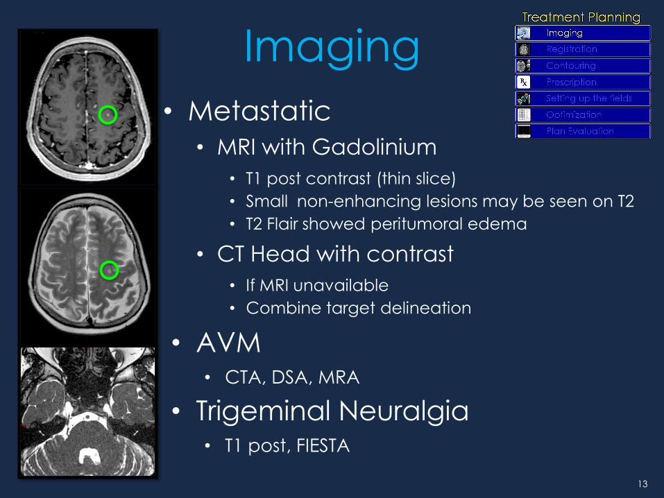
• Metastatic
• MRI with Gadolinium
• T1 post contrast (thin slice)
• Small non-enhancing lesions may be seen on T2
• T2 Flair showed peritumoral edema
• CT Head with contrast
• If MRI unavailable
• Combine target delineation
• AVM • CTA, DSA, MRA
• Trigeminal Neuralgia • T1 post, FIESTA
Imaging

14
B Zhang et al., Phys. Med. Biol. 55 (2010) 6601-6615
TG-54 “MRI contains distortions which
impede direct correlation with
CT data at the level required for
SRS”
TG-117 Use of MRI data in Treatment
Planning and Stereotactic
Procedures – Spatial Accuracy
and Quality Control Procedures
Gradient nonlinearity distortion, Siebert et al, ASTRO 2014

15
Planning CT
• Slice Size (< 1.5 mm)
• Spatial resolution of Z axis
• Thick slices: more partial volume
averaging.
• FOV (Pixel = FOV/matrix)
• Smaller is better
• Body
• Immobilizer / Registration
• Target localization
16
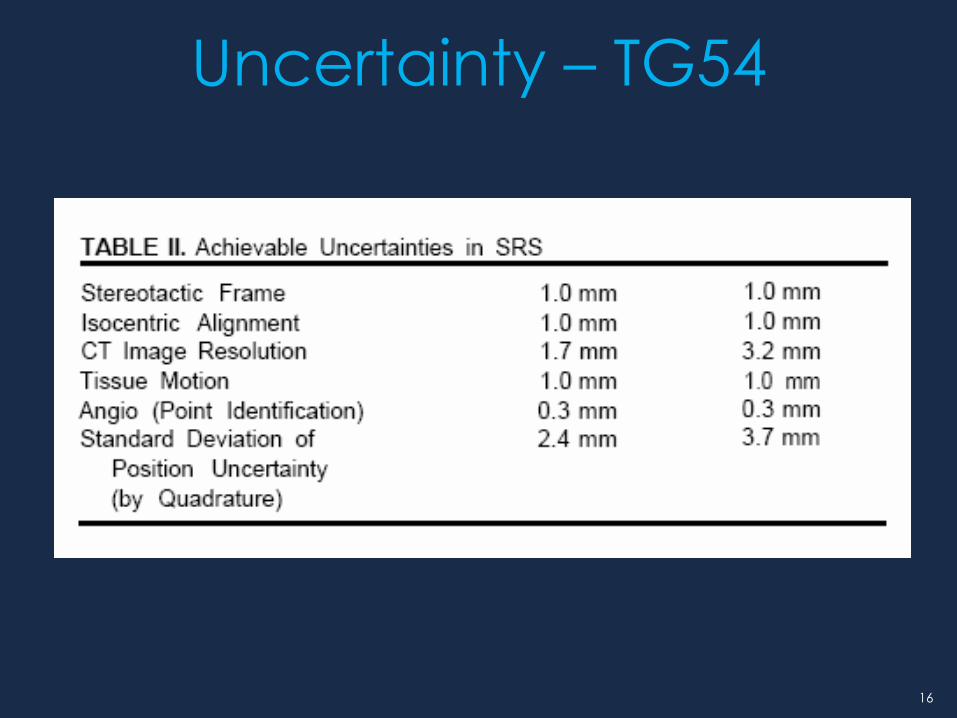
Uncertainty – TG54

17
Planning CT - IGRT
DRR_1 mm CT DRR_2 mm CT DRR_3 mm CT
Bellon et al., J. Radiosurgery and SBRT, 3, (2014)
Murphy et al., Med. Phys., 26 (2), (1999)
DRR 3mm - DRR 2mm DRR 2mm - DRR 1mm

18
What is the most appropriate imaging
modality for target delineation of brain
metastases?
SAM Question 2.
2%
0%
83%
14%
1% 1. Digital subtraction angiography (DSA)
2. MRI T2 weighted FLAIR
3. MRI T1weighted + Contrast
4. Scout image
5. Computed tomography

19
What is the most appropriate imaging
modality for target delineation of brain
metastases?
Ref: Kathleen R. Fink, James R. Fink, “Imaging of brain metastases” Surgical Neurology International. Vol.4, s209-s219 (2013)
Answer: 3. – MRI T1 FS + Contrast

20
Registration
• Benchmark Test for Cranial CT/MR Registration
K. Ulin et al., IJROBP, 77 (5), 1584-1589 (2010)
• 45 Institutions and 11 software systems
• Average error: 1.8 mm
• MR 2.0 mm Thickness, CT 2.5 mm Thickness
• Manual registration: significant better result
CT/CT registration CT/MR registration
21
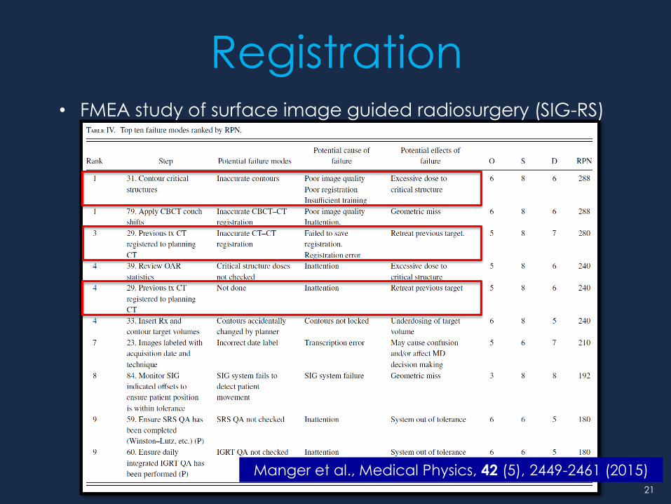
Registration
Manger et al., Medical Physics, 42 (5), 2449-2461 (2015)
• FMEA study of surface image guided radiosurgery (SIG-RS)

22
• Tested 6 SRS TPS platforms
• Phantom study shows -3.6-22% vol. variation
• Most of platforms & algorithm overestimated
• Large variation: small target < 0.4 cc, near the
end slice
Contouring

23
• Randomized Trial to 1-mm versus 3-mm expansion with IG-SRS
• The local recurrence rate was low for both arms (<10% 12 months after SRS)
• Biopsy-proven radionecrosis was more frequently observed in the 3-mm arm
• Suggest a 1-mm margin is appropriate for IG-SRS
Planning Target Volume
Kirkpatrick et al., IJROBP, 91 (1) 100–108, (2015)
24
• Treatment regimens
• Target volume (RTOG 90-05)
• Target location
• Pre-existing edema
• Pre-existing neurologic deficit
• Pathology
• Previous treatment
Prescription

25
Beam Geometry
J D Bourland and K P McCollough,
IJROBP, 28(2). 471-479, (1994)
• Static , DCA, IMRS,
VMAT approach
similar solid angle
• Avoid collision
• Reasonable number
of beams
• BEV play
• Select isocenter

26
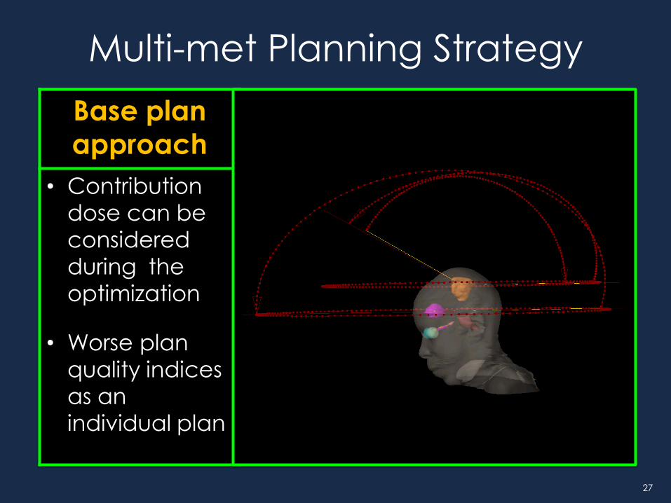
Multi-met Planning Strategy
Multi-iso approach
Based plan approach
Single-iso approach
• Relatively
easier to
achieve good
plan quality
• Less influenced
by setup
uncertainty
• Hard to control
sum dose
• Contribution
dose can be
considered
during the
optimization
• Worse plan
quality indices
as an
individual plan
• Need better
understanding
for planning
tools
• Requires
accurate
patient
positioning /
monitoring
method
27
Multi-met Planning Strategy
Base plan approach
• Contribution
dose can be
considered
during the
optimization
• Worse plan
quality indices
as an
individual plan

28
Multi-met Planning Strategy
Single-iso approach
• Need better
understanding
of planning
tools
• Requires
accurate
patient
positioning /
monitoring
method

29
IMRS vs. VMAT
JZ Wang et al, Medical Dosimetry 37, 31-36, (2012)

30
Multiple Metastases
Kang et al., Medical Physics, 37 (8), 4146-4154 (2010)
< Island blocking problem> < Shadow>

31
• Constraints (GTV, CTV, PTV, OARs)
• NTO or Tuning Structures
• MU constraint
• Optimization resolution
• Calc. grid size
Plan optimization

32
• TG-101
Constraints
Serial
Tissue
Max
vol.
(cc)
One fraction Three fraction Five fraction
End point Threshold
dose (Gy)
Max point
dose
(Gy)
Threshold
dose (Gy)
Max point
dose
(Gy)
Threshold
dose (Gy)
Max point
dose
(Gy)
Optic pathway
<0.2 8 10 15.3 17.4 23 23 Neuritis
Cochlea 9 17.1 25 Hearing loss
Brainstem (not medulla)
<0.5 10 15 18 23.1 23 31 Cranial
neuropathy
Spinal cord and medulla
<0.35 <1.2
10 7
14 18
12.3 21.9
23
14.5 30
Myelitis
• Lens Max. dose <10 Gy (1 fx)
• Normal Brain V10 < 12 cc or V12 < 10 cc
• Cranial Nerves (fifth, seventh and eighth CN)12.5-15 Gy (Flicker et al., IJROBP 2004)

33
Plan optimization – MU
Field Arc 1 Arc 2 Arc 3
Plan A 4116 2105 2105
Plan B 3488 (18% ↓) 1794 (17% ↓) 1794 (17% ↓)

34
Normal brain dose
G Minniti et al, Radiation Oncology 2011, 6:48
• V10 and V12 volumes greater than 4.5-7.7 and 6.0-10.9 cc carry >10% risk of
symptomatic radiation necrosis , respectively
35
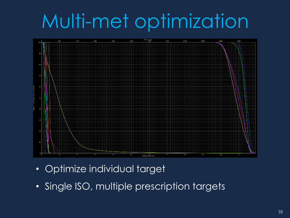
Multi-met optimization
• Optimize individual target
• Single ISO, multiple prescription targets
36
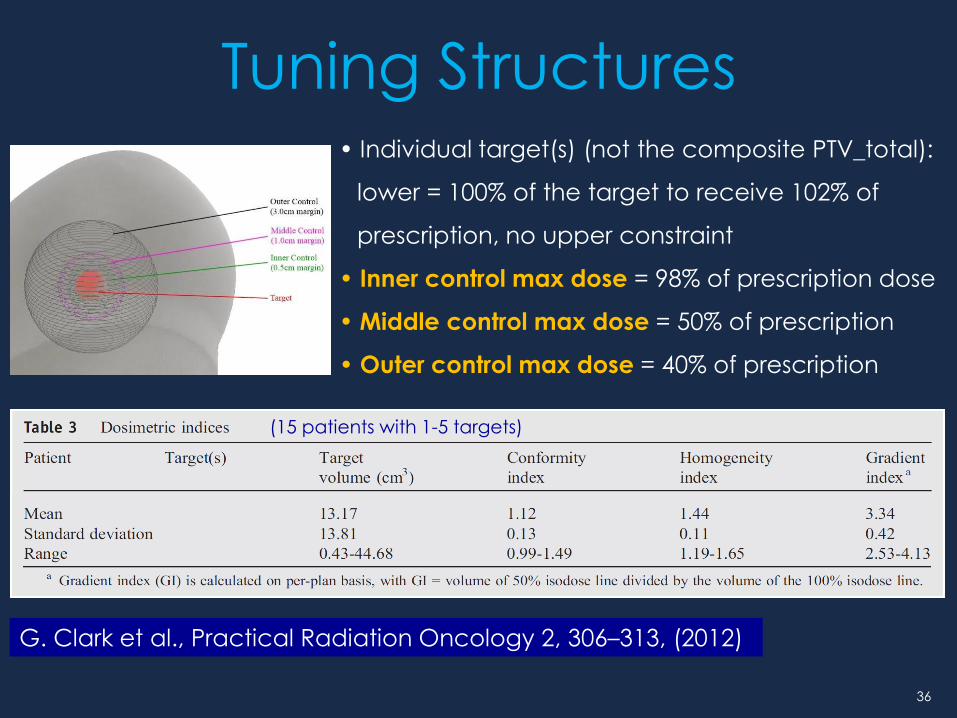
G. Clark et al., Practical Radiation Oncology 2, 306–313, (2012)
• Individual target(s) (not the composite PTV_total):
lower = 100% of the target to receive 102% of
prescription, no upper constraint
• Inner control max dose = 98% of prescription dose
• Middle control max dose = 50% of prescription
• Outer control max dose = 40% of prescription
(15 patients with 1-5 targets)
Tuning Structures

37
Calculation Grid Size
Chung et al., Phys. Med. Biol, 15, 4841-4856 (2006)

38
• Expected effects for SRS case
• Calculation accuracy
• Max dose
• Conformity Index
• Gradient
• DVH
Calculation Grid Size
Grid size: 2.5 mm Grid size: 1.5 mm

39
Plan Evaluation
• Target coverage • DVH evaluation
• Location of hot and cold spots
• Dose to Organ at Risk (OAR) • DVH evaluation
• Conformity, Gradient, Homogeneity
• Normal tissue irradiated
• Delivery efficiency
• Number of MU
40
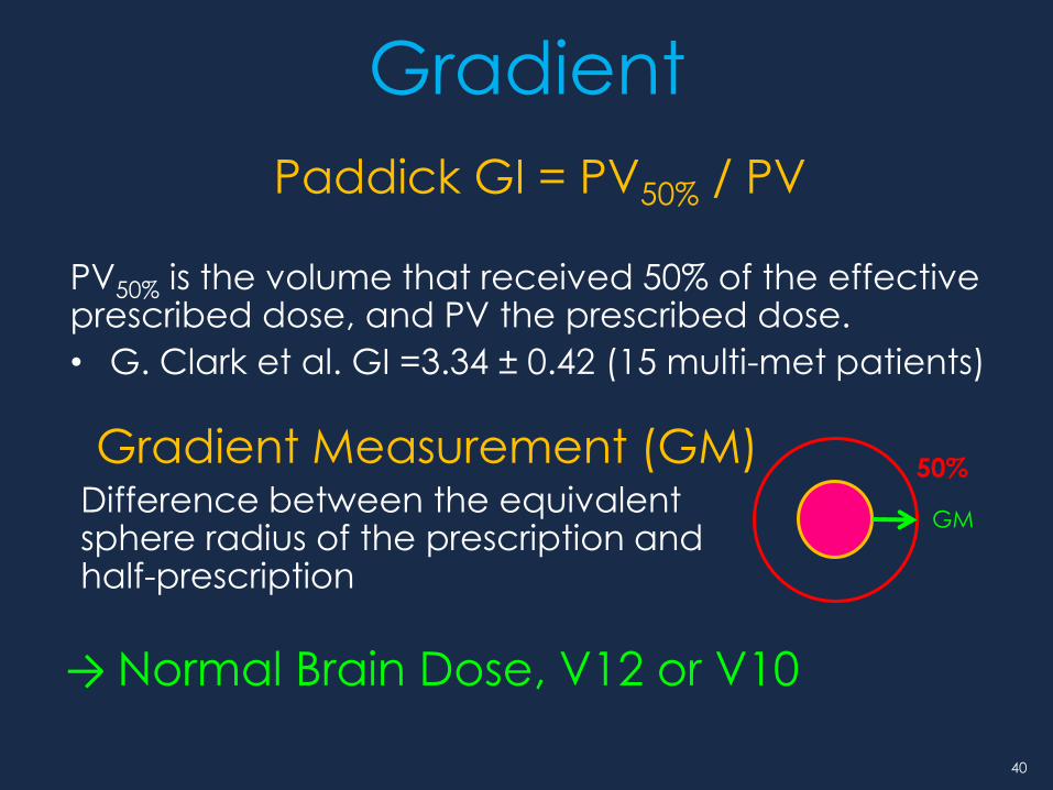
Gradient
Paddick GI = PV50% / PV
PV50% is the volume that received 50% of the effective prescribed dose, and PV the prescribed dose.
• G. Clark et al. GI =3.34 ± 0.42 (15 multi-met patients)
50%
GM
Gradient Measurement (GM) Difference between the equivalent sphere radius of the prescription and half-prescription
→ Normal Brain Dose, V12 or V10

41
RTOG CI = PV / TV
PV = The prescription volume
TV = The target volume
Paddick CI =(TVPV)2/TV×PV
TV = Target volume
PV = prescription volume
TVPV = Target volume within the prescribed isodose cloud
• G. Clark et al : CI =1.12 ± 0.13 (15 multi-met patients)
• G. Kim et al : CI = 1.14 ± 0.18 (55 multi-met patients)
Conformity

42
What should not be used when treatment
planning for small size multi-metastases?
SAM Question 3.
1%
2%
31%
65%
1% 1. High resolution MRI
2. Co-planar beams
3. Individual PTV optimization
4. Smaller calculation grid size
5. Thin slice planning CT
43
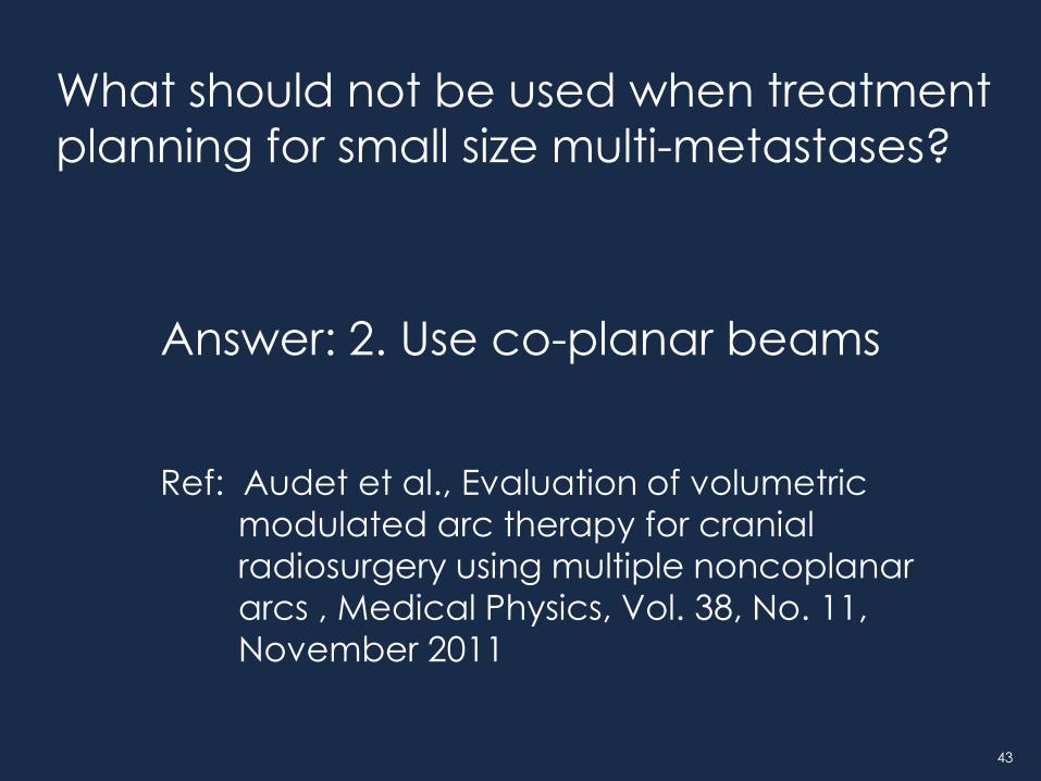
What should not be used when treatment
planning for small size multi-metastases?
Ref: Audet et al., Evaluation of volumetric
modulated arc therapy for cranial
radiosurgery using multiple noncoplanar
arcs , Medical Physics, Vol. 38, No. 11,
November 2011
Answer: 2. Use co-planar beams

44
Acknowledgements • Todd Pawlicki, PhD
• Mariel Conell, CMD
• Jane Uhl, CMD
• Ryan Manger, PhD
• Adam York, PhD
• Kevin Murphy, MD
• Jona Hattangadi, MD
• Parag Sanghvi, MD
• Clark Chen MD PhD