
ml570msg
235
ProLiant ML570 Maintenance and Service Guide First Edition (April 2000) Part Number 122821-001 Spare Part Number 174032-001 Compaq Computer Corporation
-
Upload
freddy-rochmana -
Category
Documents
-
view
39 -
download
0
Transcript of ml570msg
ProLiant ML570 Maintenance and Service Guide
First Edition (April 2000) Part Number 122821-001 Spare Part Number 174032-001 Compaq Computer Corporation
Notice © 2000 Compaq Computer Corporation.
Compaq, ProLiant, Deskpro, Compaq Insight Manager, ROMPaq, SmartStart, and the Compaq logo are registered with the U.S. Patent and Trademark Office. Netelligent is a trademark and service mark of Compaq Information Technologies Group, L.P. Microsoft, MS-DOS, Windows, and Windows NT are registered trademarks of Microsoft Corporation in the United States and other countries. Intel and Pentium are registered trademarks and Celeron and Xeon are trademarks of Intel Corporation in the United States and other countries. UNIX is a registered trademark of The Open Group. All other product names mentioned herein may be trademarks or registered trademarks of their respective companies.
Compaq shall not be liable for technical or editorial errors or omissions contained herein. The information in this document is subject to change without notice.
The information in this publication is subject to change without notice and is provided “AS IS” WITHOUT WARRANTY OF ANY KIND. THE ENTIRE RISK ARISING OUT OF THE USE OF THIS INFORMATION REMAINS WITH RECIPIENT. IN NO EVENT SHALL COMPAQ BE LIABLE FOR ANY DIRECT, CONSEQUENTIAL, INCIDENTAL, SPECIAL, PUNITIVE OR OTHER DAMAGES WHATSOEVER (INCLUDING WITHOUT LIMITATION, DAMAGES FOR LOSS OF BUSINESS PROFITS, BUSINESS INTERRUPTION OR LOSS OF BUSINESS INFORMATION), EVEN IF COMPAQ HAS BEEN ADVISED OF THE POSSIBILITY OF SUCH DAMAGES. THE FOREGOING SHALL APPLY REGARDLESS OF THE NEGLIGENCE OR OTHER FAULT OF EITHER PARTY AND REGARDLESS OF WHETHER SUCH LIABILITY SOUNDS IN CONTRACT, NEGLIGENCE, TORT, OR ANY OTHER THEORY OF LEGAL LIABILITY, AND NOTWITHSTANDING ANY FAILURE OF ESSENTIAL PURPOSE OF ANY LIMITED REMEDY.
The limited warranties for Compaq products are exclusively set forth in the documentation accompanying such products. Nothing herein should be construed as constituting a further or additional warranty. Compaq ProLiant ML570 Maintenance and Service Guide First Edition (April 2000) Part Number 122821-001 Spare Part Number 174032-001
Contents
About This Guide Symbols in Text .......................................................................................................................ix Compaq Technician Notes ......................................................................................................x Rack Stability ............................................................................................................................x Getting Help..............................................................................................................................xi
Compaq Technical Support............................................................................................xi Compaq Website..............................................................................................................xi Compaq Authorized Reseller.........................................................................................xi
Chapter 1 Illustrated Parts Catalog
Chassis Components Exploded View................................................................................ 1-2 Chassis Components Spare Parts List ............................................................................... 1-3 System Components Exploded View................................................................................ 1-4 System Components Spare Parts List................................................................................ 1-5 Electronics Drawer System Components Exploded View............................................. 1-6 Electronics Drawer System Components Spare Parts List............................................ 1-7
Chapter 2 Removal and Replacement Procedures
Electrostatic Discharge Information.................................................................................. 2-2 Symbols on Equipment........................................................................................................ 2-3 Preparation Procedures ........................................................................................................ 2-4
Hot-Pluggable Parts...................................................................................................... 2-4 Non-Hot-Pluggable Parts............................................................................................. 2-4 Powering Down the Server ......................................................................................... 2-5 Rack Warnings.............................................................................................................. 2-6 Server Warnings and Precautions.............................................................................. 2-6
Locking Casters..................................................................................................................... 2-8 Front Bezel Door (Tower Model Only)............................................................................ 2-9 Access Panel (Tower and Rack)....................................................................................... 2-10 Rack-Mount Bezel (Rack Model Only).......................................................................... 2-11 CPU Fan Air Baffle ............................................................................................................ 2-12 Fans ....................................................................................................................................... 2-13
Hot-Plug System Fans................................................................................................ 2-14 System Fan Basket...................................................................................................... 2-15 System Fan Basket Adapter with Cable .................................................................. 2-16 Hot-Plug Hard Drive Fans......................................................................................... 2-17 Hard Drive Fan Cable and Cable Bracket .............................................................. 2-18
iv Compaq ProLiant ML570 Maintenance and Service Guide
Removal and Replacement Procedures continued
Hard Drive Fan Air Baffle ................................................................................................ 2-19 Removable Media Area and Mass Storage Devices..................................................... 2-20
SCSI Hard Drive Blanking Panel............................................................................. 2-21 Hot-Plug Hard Drives ................................................................................................ 2-22 Hot-Plug SCSI Hard Drives...................................................................................... 2-23 Hard Drive Cage with Backplane Board ................................................................ 2-24 Removable Media Blanking Panel........................................................................... 2-26 Removable Media Devices........................................................................................ 2-27 CD-ROM Drive........................................................................................................... 2-28 Diskette Drive.............................................................................................................. 2-29
Cable Routing Diagrams ................................................................................................... 2-30 System Board Powe r Cables ..................................................................................... 2-30 Diskette and CD-ROM Drive Cables ...................................................................... 2-31 Hard Drive Fans Signal Cables ................................................................................ 2-32 Peripheral Board Cables ............................................................................................ 2-32 Power Backplane Board Cables ............................................................................... 2-33
Electronics Drawer ............................................................................................................. 2-34 Memory ................................................................................................................................ 2-36
Memory Expansion Board ........................................................................................ 2-37 Dual Inline Memory Module (DIMM) Combinations ......................................... 2-38 Dual Inline Memory Modules (DIMMs)................................................................ 2-39
Peripheral Board (Non-Hot-Pluggable) .......................................................................... 2-40 I/O Expansion Boards........................................................................................................ 2-41
Hot-Pluggable I/O Expansion Boards..................................................................... 2-41 Non-Hot-Pluggable I/O Expansion Board .............................................................. 2-44
Compaq NC3123 Fast Ethernet NIC PCI 10/100 Wake on LAN (WOL) Controller .................................................................................... 2-45 PCI Hot Plug LED Switchboard ...................................................................................... 2-46 Processors, Terminator Boards, and Processor Cage ................................................... 2-47
Processors..................................................................................................................... 2-47 Terminator Boards...................................................................................................... 2-49 Processor Cage ............................................................................................................ 2-50
Hot-Plug Power Supplies .................................................................................................. 2-51 Power Supply Blanking Panel .......................................................................................... 2-53 Power Backplane Board .................................................................................................... 2-54 Power On/Standby Switch and Cable Assembly........................................................... 2-55 Insulator Basket................................................................................................................... 2-56 System Board....................................................................................................................... 2-57 Replacement Battery .......................................................................................................... 2-58
Chapter 3 Diagnostics and Troubleshooting
Diagnostic Tools Utility Overview.................................................................................... 3-2 Default Configuration .......................................................................................................... 3-4
Default Configuration Messages ................................................................................ 3-4 INSPECT ........................................................................................................................ 3-4
Utilities Access...................................................................................................................... 3-5 Running the Utilities from the System Partition ..................................................... 3-5 Running the Utilities from Diskette........................................................................... 3-6 Running the Utilities from the Compaq SmartStart and Support Software CD................................................................................................... 3-6

Contents v
Power-On Self-Test (POST)............................................................................................... 3-7 POST Error Messages .................................................................................................. 3-7
vi Compaq ProLiant ML570 Maintenance and Service Guide
Diagnostics and Troubleshooting continued
Diagnostics Software.......................................................................................................... 3-22 Steps for Diagnostics.................................................................................................. 3-22 100 – 199, Primary Processor Test Error Codes ................................................... 3-23 200 – 299, Memory Test Error Codes..................................................................... 3-24 300 – 399, Keyboard Test Error Codes................................................................... 3-25 400 – 499, Parallel Printer Test Error Codes ......................................................... 3-25 500 – 599, Graphics Display Unit Test Error Codes ............................................ 3-26 600 – 699, Diskette Drive Test Error Codes .......................................................... 3-27 1100 – 1199, Serial Test Error Codes ..................................................................... 3-28 1200 – 1299, Modem Communications Test Error Codes .................................. 3-28 1700 – 1799, Hard Drive Test Error Codes............................................................ 3-29 1900 – 1999, Tape Drive Test Error Codes............................................................ 3-30 6000 – 6099, Compaq Network Interface Controller (NIC) Test Error Codes ......................................................................................................... 3-30 6500 – 6599, SCSI Hard Drive Test Error Codes ................................................. 3-31 6600 – 6699, SCSI/IDE CD-ROM Drive Test Error Codes................................ 3-31 6700 – 6799, SCSI Tape Drive Test Error Codes ................................................. 3-32 8600 – 8699, Pointing Device Interface Test Error Codes .................................. 3-32
Array Diagnostic Utility (ADU) ...................................................................................... 3-33 Integrated Management Log (IML)................................................................................. 3-53
Multiple Ways of Viewing the Information Management Log (IML) .............. 3-53 Event List ..................................................................................................................... 3-55 Event Messages ........................................................................................................... 3-55
Rapid Error Recovery ........................................................................................................ 3-58 Automatic Server Recovery-2 (ASR-2) .................................................................. 3-58 Server Health Logs..................................................................................................... 3-68 ASR-2 Integrated Management Log (IML) Messages ......................................... 3-68 Storage Fault Recovery Tracking............................................................................. 3-71 Storage Automatic Reconstruction.......................................................................... 3-71 Network Interface Fault Recovery Tracking.......................................................... 3-71 Memory Fault Recovery Tracking........................................................................... 3-71
Remote Management Features ......................................................................................... 3-72 ROMPaq Error Recovery Options................................................................................... 3-73
ROMPaq Disaster Recovery ..................................................................................... 3-73 Redundant ROM Image Recovery ........................................................................... 3-74
Compaq Insight Manager.................................................................................................. 3-75 Features of Compaq Insight Manager..................................................................... 3-75 Compaq Insight Manager Software Architecture.................................................. 3-76
Chapter 4 Connectors, Switches, and LED Status Indicators
Connectors ............................................................................................................................. 4-2 Rear Panel Connectors................................................................................................. 4-2 System Board Connectors ........................................................................................... 4-3 Peripheral Board Connectors...................................................................................... 4-4 Power Backplane Board Connectors......................................................................... 4-5
Switches.................................................................................................................................. 4-6 System Maintenance Switch Settings (SW1)........................................................... 4-6 Clearing CMOS............................................................................................................. 4-7 Processor Configuration Switch (SW4) and System ID Switch (SW6) .............. 4-8 System Board ID/Miscellaneous Switch (SW6) ..................................................... 4-9
Contents vii
Connectors, Switches, and LED Status Indicators continued
LED Status Indicators........................................................................................................ 4-10 Power Switch and Front Panel LED Indicators ..................................................... 4-11 Hot-Plug Fan LED Indicators ................................................................................... 4-12 Interlock Status LED Indicators ............................................................................... 4-13 Internal Diagnostics Display (IDD)......................................................................... 4-14 PCI Hot Plug Switchboard LED Indicators ........................................................... 4-15 RJ-45 Network Connector Status LED Indicators ................................................ 4-17 Hot-Plug Power Supply Diagnostic LED Indicators ............................................ 4-18 CD-ROM Drive LED Indicator................................................................................ 4-19 Diskette Drive LED Indicator................................................................................... 4-19 Hot-Plug Hard Drive LED Indicators ..................................................................... 4-20
Chapter 5 Physical and Operating Specifications
System Unit............................................................................................................................ 5-2 Hot-Plug Power Supply ....................................................................................................... 5-3 SDRAM Dual Inline Memory Modules (DIMMs)......................................................... 5-4 1.44-MB Diskette Drive ...................................................................................................... 5-4 IDE CD-ROM Drive ............................................................................................................ 5-5 NC3123 Fast Ethernet NIC PCI 10/100 Wake on LAN (WOL) .................................. 5-6 Integrated Dual-Channel Wide Ultra2 SCSI Controller ................................................ 5-7 Hot-Plug Hard Drives .......................................................................................................... 5-8 Smart Array 4200 Controller .............................................................................................. 5-9
Index


About This Guide
This maintenance and service guide is designed to be used as a reference, spare parts catalog, troubleshooting, and step-by-step disassemb ly guide when servicing the Compaq ProLiant™ ML570 server.
Symbols in Text These symbols may be found in the text of this guide. They have the following meanings.
WARNING: Text set off in this manner indicates that failure to follow directions in the warning could result in bodily harm or loss of life.
CAUTION: Text set off in this manner indicates that failure to follow directions could result in damage to equipment or loss of information.
IMPORTANT: Text set off in this manner presents clarifying information or specific instructions.
NOTE: Text set off in this manner presents commentary, sidelights, or interesting points of information.
x Compaq ProLiant ML570 Maintenance and Service Guide
Compaq Technician Notes
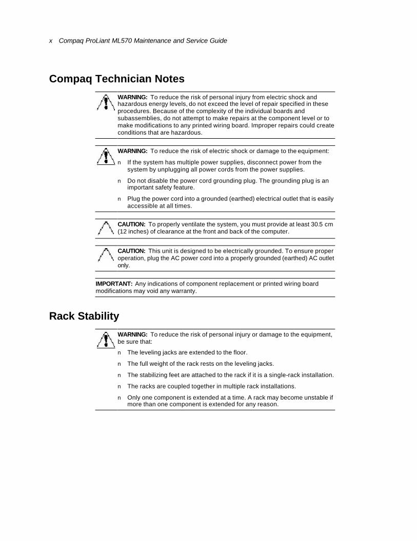
WARNING: To reduce the risk of personal injury from electric shock and hazardous energy levels, do not exceed the level of repair specified in these procedures. Because of the complexity of the individual boards and subassemblies, do not attempt to make repairs at the component level or to make modifications to any printed wiring board. Improper repairs could create conditions that are hazardous.
WARNING: To reduce the risk of electric shock or damage to the equipment:
n If the system has multiple power supplies, disconnect power from the system by unplugging all power cords from the power supplies.
n Do not disable the power cord grounding plug. The grounding plug is an important safety feature.
n Plug the power cord into a grounded (earthed) electrical outlet that is easily accessible at all times.
CAUTION: To properly ventilate the system, you must provide at least 30.5 cm (12 inches) of clearance at the front and back of the computer.
CAUTION: This unit is designed to be electrically grounded. To ensure proper operation, plug the AC power cord into a properly grounded (earthed) AC outlet only.
IMPORTANT: Any indications of component replacement or printed wiring board modifications may void any warranty.
Rack Stability
WARNING: To reduce the risk of personal injury or damage to the equipment, be sure that:
n The leveling jacks are extended to the floor.
n The full weight of the rack rests on the leveling jacks.
n The stabilizing feet are attached to the rack if it is a single-rack installation.
n The racks are coupled together in multiple rack installations.
n Only one component is extended at a time. A rack may become unstable if more than one component is extended for any reason.
About This Guide xi
Getting Help If you have a problem and have exhausted the information in this guide, you can get further information and other help as described in the following sections:
Compaq Technical Support
In North America, call the Compaq Technical Phone Support Center at 1-800-OK-COMPAQ. This service is available 24 hours a day, 7 days a week. For continuous quality improvement, calls may be recorded or monitored.
Outside North America, call the nearest Compaq Technical Support Phone Center. Telephone numbers for worldwide Technical Support Centers are listed on the Compaq website. Access the Compaq website by logging on to the Internet at
http://www.compaq.com
Be sure to have the following information available before you call Compaq:
n Technical support registration number (if applicable)
n Product serial number
n Product model name and number
n Applicable error messages
n Add-on boards and hardware names and revision level
n Third-party software names and revision level
n Operating system type and revision level
Compaq Website
The Compaq website has information on this product as well as the latest drivers and Flash ROM images. You can access the Compaq website by logging on to the Internet at
http://www.compaq.com
Compaq Authorized Reseller
For the name of your nearest Compaq authorized reseller:
n In the United States, call 1-800-345-1518.
n In Canada, call 1-800-263-5868.
n Elsewhere, see the Compaq website for locations and telephone numbers.
Chapter 1
Illustrated Parts Catalog
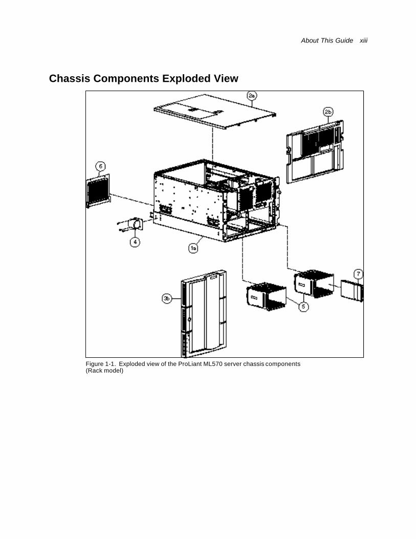
This chapter provides the illustrated parts breakdown and a spare parts list for the Compaq ProLiant™ ML570 server. See Table 1-1, Table 1-2, and Table 1-3 for the names of referenced spare parts.
About This Guide xiii
Chassis Components Exploded View
Figure 1-1. Exploded view of the ProLiant ML570 server chassis components (Rack model)
xiv Compaq ProLiant ML570 Maintenance and Service Guide
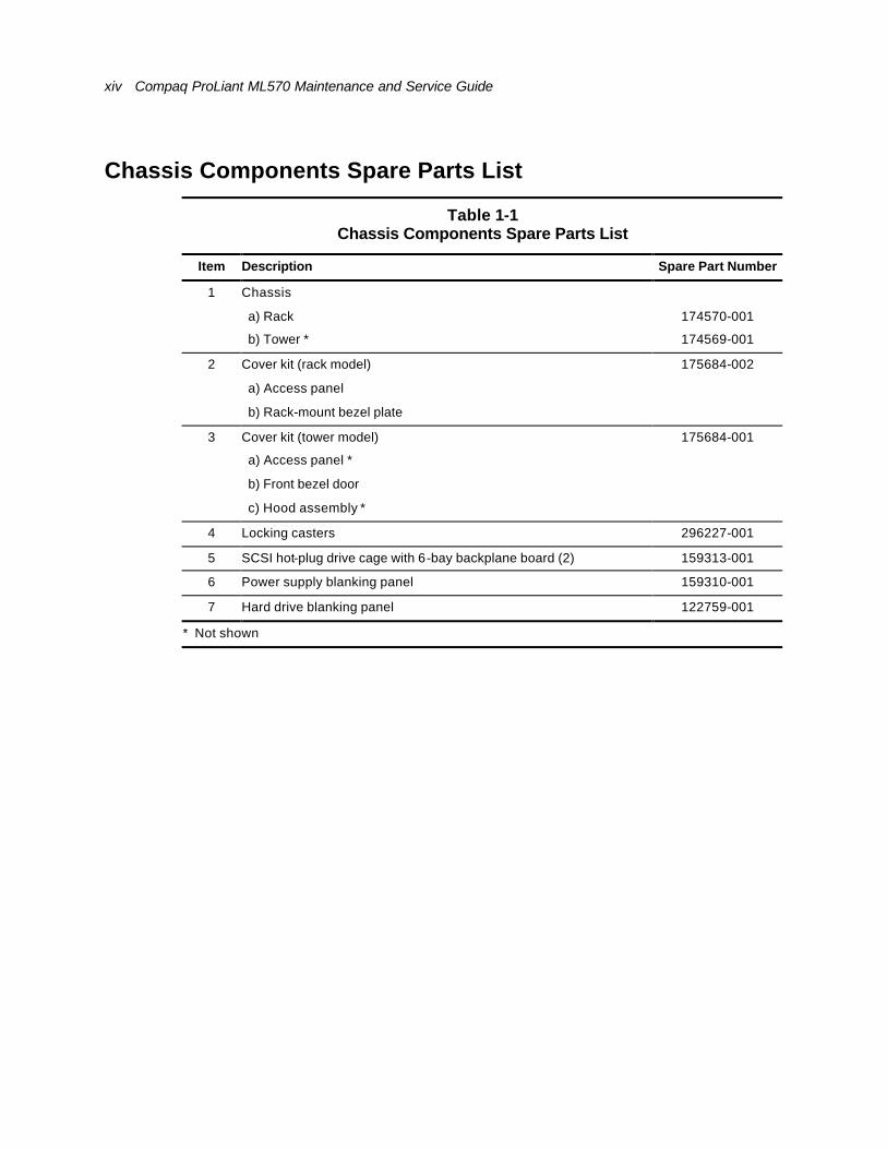
Chassis Components Spare Parts List
Table 1-1 Chassis Components Spare Parts List
Item Description Spare Part Number
1 Chassis
a) Rack 174570-001
b) Tower * 174569-001
2 Cover kit (rack model) 175684-002
a) Access panel
b) Rack-mount bezel plate
3 Cover kit (tower model) 175684-001
a) Access panel *
b) Front bezel door
c) Hood assembly *
4 Locking casters 296227-001
5 SCSI hot-plug drive cage with 6-bay backplane board (2) 159313-001
6 Power supply blanking panel 159310-001
7 Hard drive blanking panel 122759-001
* Not shown
About This Guide xv
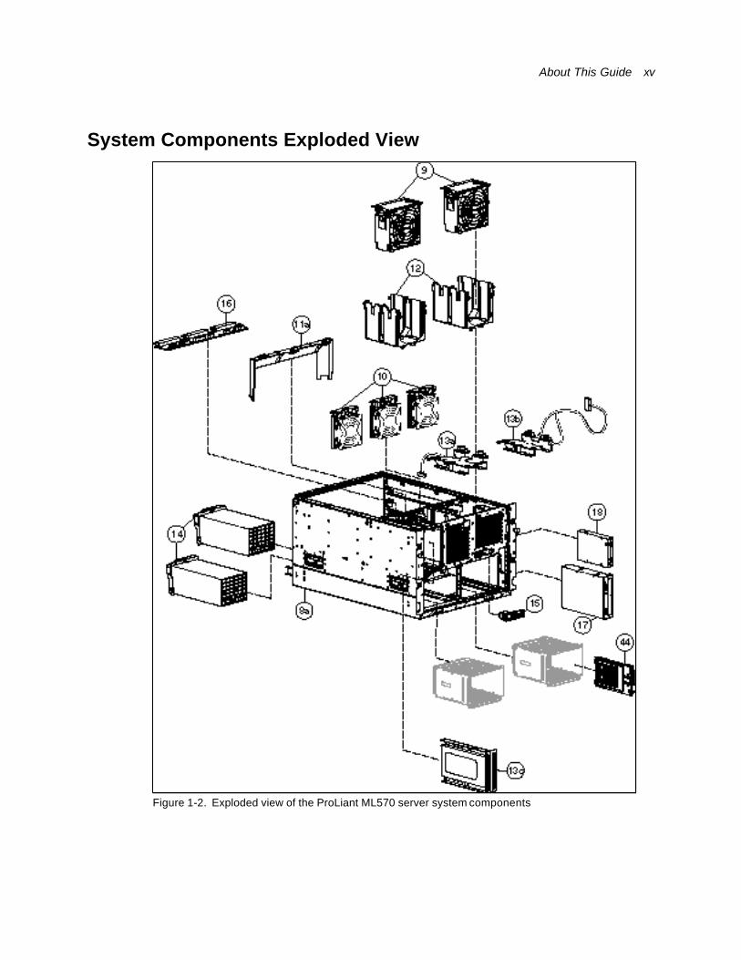
System Components Exploded View
Figure 1-2. Exploded view of the ProLiant ML570 server system components

xvi Compaq ProLiant ML570 Maintenance and Service Guide
System Components Spare Parts List
Table 1-2 System Components Spare Parts List
Item Description Spare Part Number
8 System chassis (same as item 1, Figure 1-1)
a) Rack 174570-001
b) Tower * 174569-001
9 Hot-plug system fan (2) 122225-001
10 Hot-plug hard drive fan (3) 161657-001
11 Miscellaneous plastics kit 178195-001
a) Hard drive fan air baffle
b) CPU fan air baffle (shown in Figure 1-3)
c) Expansion board slot release lever (port-colored and beach gray) *
d) PCI retainers *
e) Option board retainers *
f) Media locking latch (green) *
12 System fan basket (2) 161658-001
13 Miscellaneous hardware kit 159321-001
a) System fan basket adapter with cable (left)
b) System fan basket adapter with cable (right)
c) Removable media bay blanking panel
14 Power supply, 450 watts, hot-plug (2) 157793-001
15 Power On/Standby switch with LED indicators 161659-001
Boards
16 Power supply backplane board, hot-plug 159314-001
Mass Storage Devices
17 CD-ROM drive 327659-001
18 1.44-MB diskette drive 123958-001
* Not shown

About This Guide xvii
Electronics Drawer System Components Exploded View
Figure 1-3. Exploded view of the ProLiant ML570 server electronics drawer system components
xviii Compaq ProLiant ML570 Maintenance and Service Guide
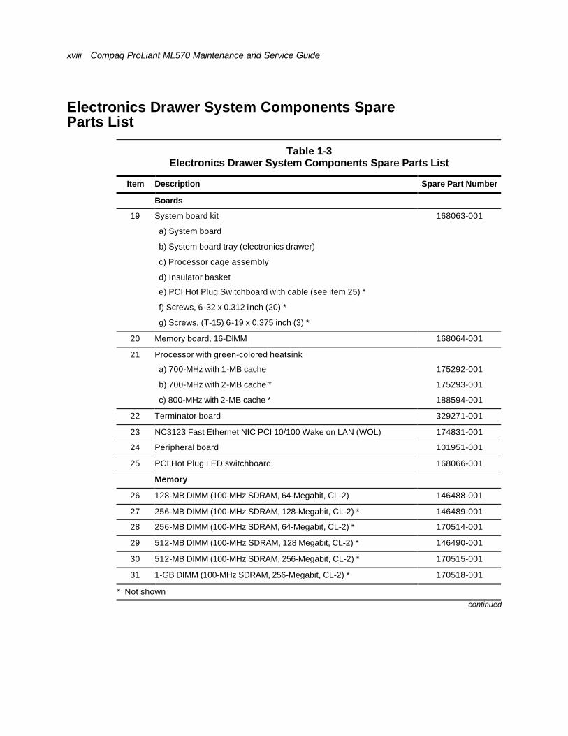
Electronics Drawer System Components Spare Parts List
Table 1-3 Electronics Drawer System Components Spare Parts List
Item Description Spare Part Number
Boards
19 System board kit 168063-001
a) System board
b) System board tray (electronics drawer)
c) Processor cage assembly
d) Insulator basket
e) PCI Hot Plug Switchboard with cable (see item 25) *
f) Screws, 6-32 x 0.312 inch (20) *
g) Screws, (T-15) 6-19 x 0.375 inch (3) *
20 Memory board, 16-DIMM 168064-001
21 Processor with green-colored heatsink
a) 700-MHz with 1-MB cache 175292-001
b) 700-MHz with 2-MB cache * 175293-001
c) 800-MHz with 2-MB cache * 188594-001
22 Terminator board 329271-001
23 NC3123 Fast Ethernet NIC PCI 10/100 Wake on LAN (WOL) 174831-001
24 Peripheral board 101951-001
25 PCI Hot Plug LED switchboard 168066-001
Memory
26 128-MB DIMM (100-MHz SDRAM, 64-Megabit, CL-2) 146488-001
27 256-MB DIMM (100-MHz SDRAM, 128-Megabit, CL-2) * 146489-001
28 256-MB DIMM (100-MHz SDRAM, 64-Megabit, CL-2) * 170514-001
29 512-MB DIMM (100-MHz SDRAM, 128 Megabit, CL-2) * 146490-001
30 512-MB DIMM (100-MHz SDRAM, 256-Megabit, CL-2) * 170515-001
31 1-GB DIMM (100-MHz SDRAM, 256-Megabit, CL-2) * 170518-001
* Not shown continued
About This Guide xix
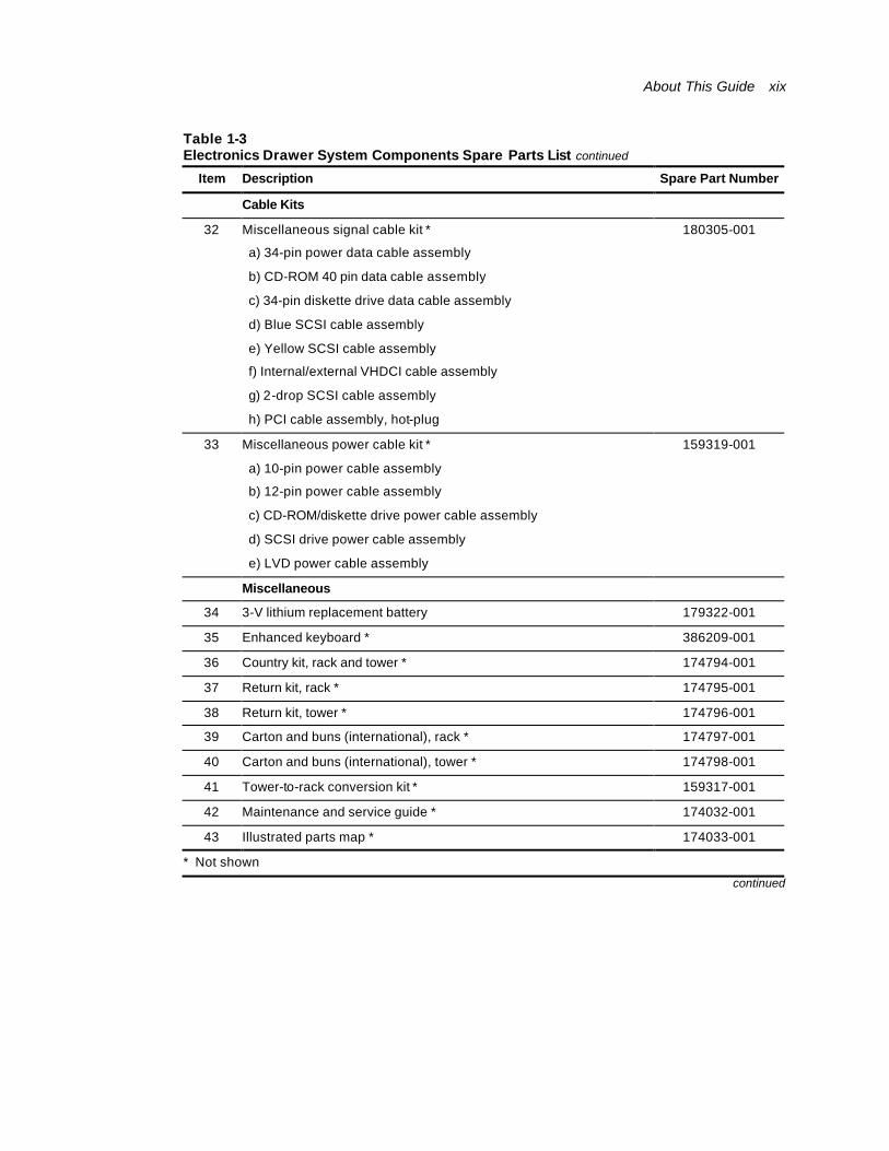
Table 1-3 Electronics Drawer System Components Spare Parts List continued
Item Description Spare Part Number
Cable Kits
32 Miscellaneous signal cable kit * 180305-001
a) 34-pin power data cable assembly
b) CD-ROM 40 pin data cable assembly
c) 34-pin diskette drive data cable assembly
d) Blue SCSI cable assembly
e) Yellow SCSI cable assembly
f) Internal/external VHDCI cable assembly
g) 2-drop SCSI cable assembly
h) PCI cable assembly, hot-plug
33 Miscellaneous power cable kit * 159319-001
a) 10-pin power cable assembly
b) 12-pin power cable assembly
c) CD-ROM/diskette drive power cable assembly
d) SCSI drive power cable assembly
e) LVD power cable assembly
Miscellaneous
34 3-V lithium replacement battery 179322-001
35 Enhanced keyboard * 386209-001
36 Country kit, rack and tower * 174794-001
37 Return kit, rack * 174795-001
38 Return kit, tower * 174796-001
39 Carton and buns (international), rack * 174797-001
40 Carton and buns (international), tower * 174798-001
41 Tower-to-rack conversion kit * 159317-001
42 Maintenance and service guide * 174032-001
43 Illustrated parts map * 174033-001
* Not shown
continued
xx Compaq ProLiant ML570 Maintenance and Service Guide
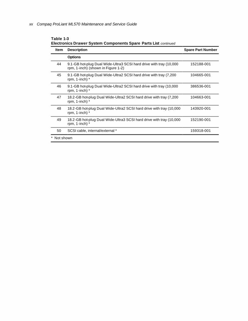
Table 1-3 Electronics Drawer System Components Spare Parts List continued
Item Description Spare Part Number
Options
44 9.1-GB hot-plug Dual Wide-Ultra3 SCSI hard drive with tray (10,000 rpm, 1-inch) (shown in Figure 1-2)
152188-001
45 9.1-GB hot-plug Dual Wide-Ultra2 SCSI hard drive with tray (7,200 rpm, 1-inch) *
104665-001
46 9.1-GB hot-plug Dual Wide-Ultra2 SCSI hard drive with tray (10,000 rpm, 1-inch) *
386536-001
47 18.2-GB hot-plug Dual Wide-Ultra2 SCSI hard drive with tray (7,200 rpm, 1-inch) *
104663-001
48 18.2-GB hot-plug Dual Wide-Ultra2 SCSI hard drive with tray (10,000 rpm, 1-inch) *
143920-001
49 18.2-GB hot-plug Dual Wide-Ultra3 SCSI hard drive with tray (10,000 rpm, 1-inch) *
152190-001
50 SCSI cable, internal/external * 159318-001
* Not shown
Chapter 2
Removal and Replacement Procedures
This chapter provides subassembly/module-level removal and replacement procedures for the Compaq ProLiant ML570 server. After completing all necessary removal and replacement procedures, run the Diagnostics program to verify that all components operate properly.
WARNING: To reduce the risk of personal injury or damage to the equipment, observe all warnings and cautions throughout the “Removal and Replacement Procedures” instructions.
WARNING: To reduce the risk of personal injury or damage to the equipment, the installation of options other than hot-plug power devices should be performed only by individuals who are qualified in servicing computer equipment and trained to deal with products capable of producing hazardous energy levels.
To service the ProLiant ML570 server, the following tools are recommended:
n Torx T-15 screwdriver
n Torx T-10 screwdriver
n Phillips screwdriver
n Nut driver
n From the Compaq SmartStart and Support Software CD:
q System Configuration Utility
q Drive Array Advanced Diagnostics
q Diagnostics
xxii Compaq ProLiant ML570 Maintenance and Service Guide
Electrostatic Discharge Information A discharge of static electricity can damage static-sensitive devices or microcircuitry. Proper packaging and grounding techniques are necessary precautions to prevent damage. To prevent electrostatic damage, observe the following precautions:
n Transport products in static-safe containers such as conductive tubes, bags, or boxes.
n Keep electrostatic-sensitive parts in their containers until they arrive at static-free stations.
n Cover workstations with approved static-dissipating material. Provide a wrist strap connected to the work surface and properly grounded (earthed) tools and equipment.
n Keep work area free of nonconductive materials such as ordinary plastic assembly aids and foam packing.
n Make sure you are properly grounded (earthed) when touching a static-sensitive component or assembly.
n Avoid touching pins, leads, or circuitry.
n Always place drives PCB assembly-side down.
n Use nonconductive field service tools.
About This Guide xxiii
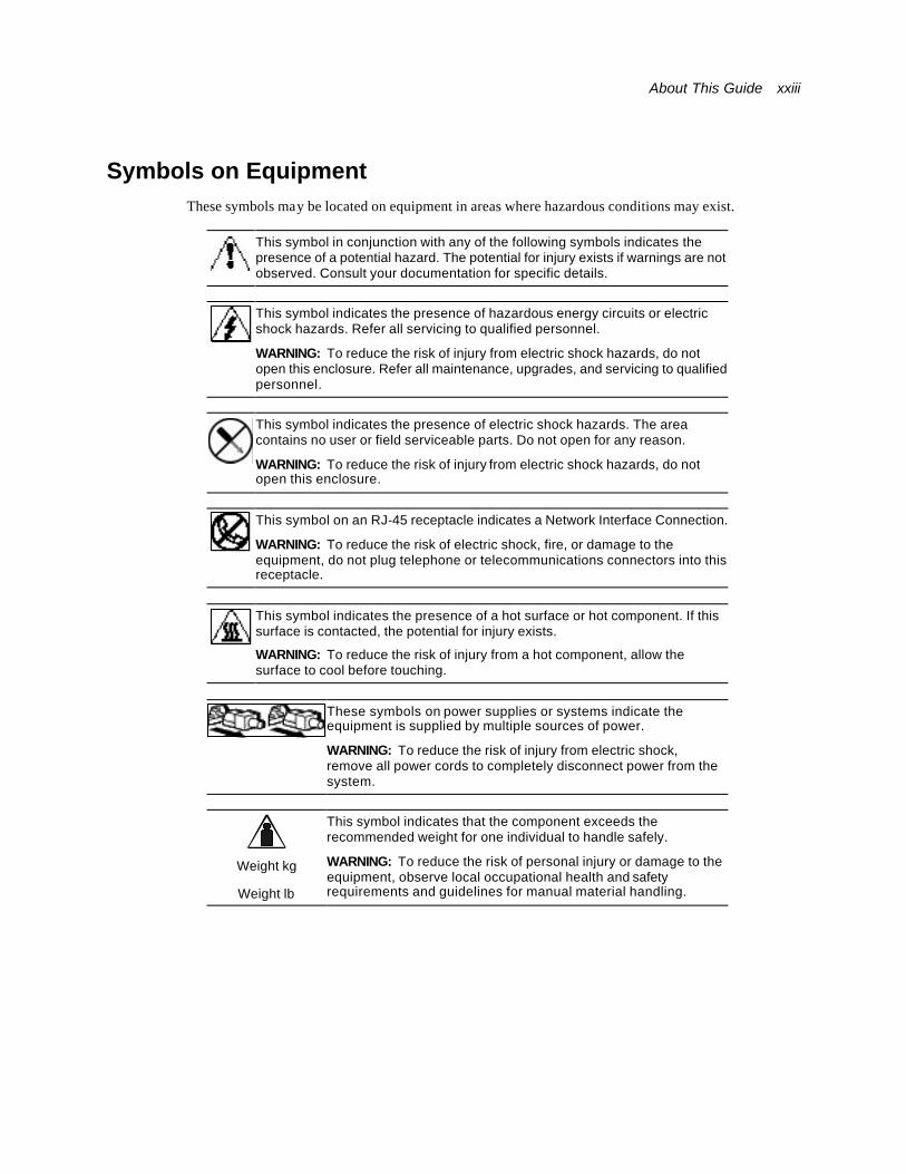
Symbols on Equipment These symbols may be located on equipment in areas where hazardous conditions may exist.
This symbol in conjunction with any of the following symbols indicates the presence of a potential hazard. The potential for injury exists if warnings are not observed. Consult your documentation for specific details.
This symbol indicates the presence of hazardous energy circuits or electric shock hazards. Refer all servicing to qualified personnel.
WARNING: To reduce the risk of injury from electric shock hazards, do not open this enclosure. Refer all maintenance, upgrades, and servicing to qualified personnel.
This symbol indicates the presence of electric shock hazards. The area contains no user or field serviceable parts. Do not open for any reason.
WARNING: To reduce the risk of injury from electric shock hazards, do not open this enclosure.
This symbol on an RJ-45 receptacle indicates a Network Interface Connection.
WARNING: To reduce the risk of electric shock, fire, or damage to the equipment, do not plug telephone or telecommunications connectors into this receptacle.
This symbol indicates the presence of a hot surface or hot component. If this surface is contacted, the potential for injury exists.
WARNING: To reduce the risk of injury from a hot component, allow the surface to cool before touching.
These symbols on power supplies or systems indicate the equipment is supplied by multiple sources of power.
WARNING: To reduce the risk of injury from electric shock, remove all power cords to completely disconnect power from the system.
Weight kg
Weight lb
This symbol indicates that the component exceeds the recommended weight for one individual to handle safely.
WARNING: To reduce the risk of personal injury or damage to the equipment, observe local occupational health and safety requirements and guidelines for manual material handling.

xxiv Compaq ProLiant ML570 Maintenance and Service Guide
Preparation Procedures The system power in the ProLiant ML570 server does not completely power down with the front panel Power On/Standby switch. The switch toggles between On and Standby, rather than On and Off. The Standby position removes power from most electronics and the drives, but portions of the power supply and some internal circuitry remain active. To completely remove all power from the system, you must disconnect all power cords from the server. For more information about removing power from the system, see “Powering Down the Server” later in this chapter. See “Server Warnings and Precautions” later in this chapter for further safety information.
IMPORTANT: Before beginning to remove any serviceable part, determine whether the part is hot-pluggable or non-hot-pluggable. Hot-pluggable devices in the ProLiant ML570 server include SCSI hard drives, fans, and power supplies.
Hot-Pluggable Parts
If the part is hot-pluggable, do not perform a power shutdown of the server. The access panel can be removed without causing system shutdown. Hot-pluggable devices in the ProLiant ML570 server includes Wide Ultra2 and Ultra3 SCSI hard drives, some expansion boards, fans, and power supplies.
IMPORTANT: It is not necessary to power down the server to replace hot-pluggable devices such as power supplies, fans, or PCI Hot Plug boards when they are not in active use.
Non-Hot-Pluggable Parts
If the part is non-hot-pluggable, the server must be shut down. Non-hot-pluggable parts include the processors, some expansion boards, DIMMs, and drive cages. See “Powering Down the Server” later in this chapter for complete powering down instructions.
WARNING: To reduce the risk of personal injury or damage to the equipment, the installation of options other than hot-pluggable power devices should be performed only by individuals who are qualified in servicing computer equipment and trained to deal with products capable of producing hazardous energy levels.
WARNING: To reduce the risk of personal injury or damage to the equipment when moving the server, be sure that:
n The access panel is securely fastened to the chassis.
n You do not use the electronics drawer handle to move the unit.
n You do not use the rack-mount bezel handles to move the unit.
About This Guide xxv
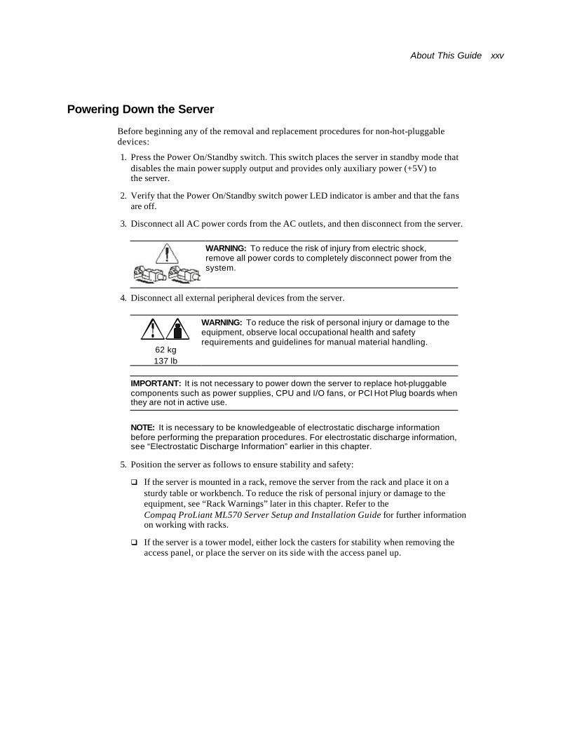
Powering Down the Server
Before beginning any of the removal and replacement procedures for non-hot-pluggable devices:
1. Press the Power On/Standby switch. This switch places the server in standby mode that disables the main power supply output and provides only auxiliary power (+5V) to the server.
2. Verify that the Power On/Standby switch power LED indicator is amber and that the fans are off.
3. Disconnect all AC power cords from the AC outlets, and then disconnect from the server.
WARNING: To reduce the risk of injury from electric shock, remove all power cords to completely disconnect power from the system.
4. Disconnect all external peripheral devices from the server.
62 kg 137 lb
WARNING: To reduce the risk of personal injury or damage to the equipment, observe local occupational health and safety requirements and guidelines for manual material handling.
IMPORTANT: It is not necessary to power down the server to replace hot-pluggable components such as power supplies, CPU and I/O fans, or PCI Hot Plug boards when they are not in active use.
NOTE: It is necessary to be knowledgeable of electrostatic discharge information before performing the preparation procedures. For electrostatic discharge information, see “Electrostatic Discharge Information” earlier in this chapter.
5. Position the server as follows to ensure stability and safety:
q If the server is mounted in a rack, remove the server from the rack and place it on a sturdy table or workbench. To reduce the risk of personal injury or damage to the equipment, see “Rack Warnings” later in this chapter. Refer to the Compaq ProLiant ML570 Server Setup and Installation Guide for further information on working with racks.
q If the server is a tower model, either lock the casters for stability when removing the access panel, or place the server on its side with the access panel up.
xxvi Compaq ProLiant ML570 Maintenance and Service Guide
Rack Warnings
WARNING: To reduce the risk of personal injury or damage to the equipment, be sure that:
n The leveling jacks are extended to the floor.
n The full weight of the rack rests on the leveling jacks.
n The stabilizing feet are attached to the rack if it is a single-rack installation.
n The racks are coupled in multiple-rack installations.
n Only one component is extended at a time. A rack may become unstable if more than one component is extended for any reason.
n You are careful when pressing the component rail release latches and sliding the component into the rack. The slide rails could pinch your fingertips.
n You load the rack from the bottom up and load the heaviest item into the rack first.
n You do not attempt to move equipment racks without adequate assistance due to their height and weight.
n You do not attempt to move an equipment rack on an incline that is greater than 10 degrees from horizontal.
n You do not attempt to move a fully loaded equipment rack. Remove equipment from the rack before moving the rack.
Server Warnings and Precautions
WARNING: To reduce the risk of personal injury or damage to the equipment:
n The ProLiant ML570 server weighs at least 62 kilograms (137 pounds) when fully assembled.
n Observe local health and safety requirements and guidelines for manual material handling.
n Obtain adequate assistance to lift and stabilize the product during installation or removal.
n Remove all pluggable power supplies and modules to reduce the weight of the product.
n Make sure that the product is properly mated with the rails. Products that are improperly mated with the rails may be unstable.

About This Guide xxvii
WARNING: To reduce the risk of electric shock or damage to the equipment:
n The installation of internal options and routine maintenance and service of this product should be performed by individuals who are knowledgeable about the procedures, precautions, and hazards associated with equipment containing hazardous energy levels.
n Allow the product to cool before removing covers and touching internal components.
n Do not use conductive tools that could bridge live parts.
n Remove all watches, rings, or loose jewelry when working in hot-plug areas of an energized server.
n The hot-plug access panel provides access to hazardous energy circuits.
n The panel should remain locked during normal operation.
-Or-
The server should be installed in a controlled access location where only qualified personnel have access to the server.
n Power down the equipment and disconnect all AC power cords before removing any access covers for non-hot-pluggable areas.
n Do not replace non-hot-pluggable components while power is applied to the product. First, shut down the product and disconnect all AC power cords.
n Do not exceed the level of repair specified in the procedures in the product documentation. All troubleshooting and repair procedures are detailed to allow only subassembly or module-level repair. Because of the complexity of the individual boards and subassemblies, do not attempt to make repairs at the component level or to make modifications to any printed wiring board. Improper repairs can create a safety hazard.
n Verify that the AC power supply branch circuit that provides power to the rack is not overloaded. Maintaining a low electric current draw reduces the risk of personal injury, fire, or damage to the equipment. The total rack load should not exceed 80 percent of the branch circuit rating. Consult the electrical authority having jurisdiction over your facility for wiring and installation requirements.
n Do not pull on a cord or cable. When unplugging from the electrical outlet, grasp the cord by the plug.
n Do not disable the power cord grounding plug. The grounding plug is an important safety feature.
n Plug the power cord into a grounded (earthed) electrical outlet that is easily accessible at all times.
CAUTION: The ProLiant ML570 server must always operate with the system unit covers and air baffles in place. Proper cooling cannot be achieved if the system unit covers or air baffles are removed for extended periods.
IMPORTANT: The installation of options and servicing of this product must be performed by individuals who are knowledgeable of the procedures, precautions, and hazards associated with equipment containing hazardous energy circuits.

xxviii Compaq ProLiant ML570 Maintenance and Service Guide
Locking Casters To remove the locking casters:
1. Perform the preparation procedures. See “Preparation Procedures” earlier in this chapter.
2. Place the server on its side, then remove the three T-25 screws securing each caster to the chassis.
3. Pull the locking casters away from the server.
Figure 2-4. Removing the locking casters
Reverse steps 1 through 3 to replace the locking casters.
About This Guide xxix
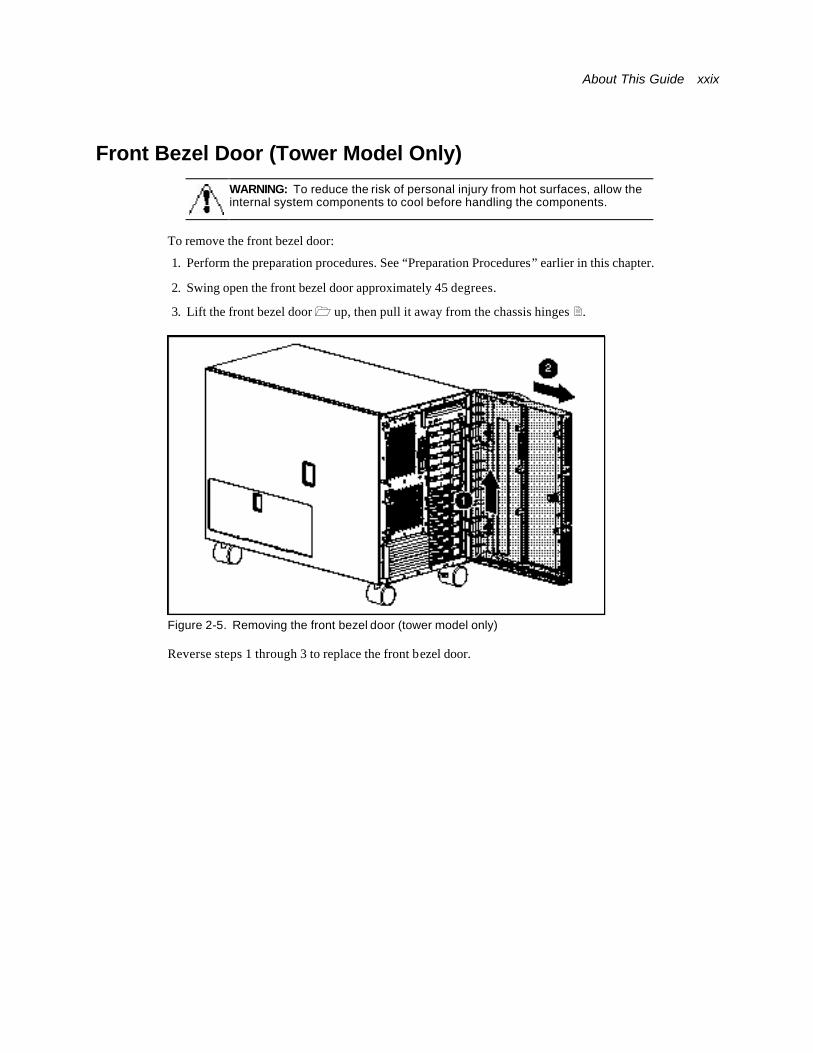
Front Bezel Door (Tower Model Only)
WARNING: To reduce the risk of personal injury from hot surfaces, allow the internal system components to cool before handling the components.
To remove the front bezel door:
1. Perform the preparation procedures. See “Preparation Procedures” earlier in this chapter.
2. Swing open the front bezel door approximately 45 degrees.
3. Lift the front bezel door 1 up, then pull it away from the chassis hinges 2.
Figure 2-5. Removing the front bezel door (tower model only)
Reverse steps 1 through 3 to replace the front bezel door.
xxx Compaq ProLiant ML570 Maintenance and Service Guide
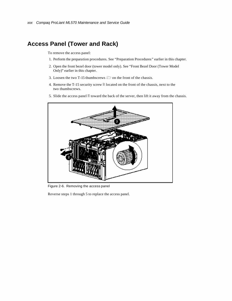
Access Panel (Tower and Rack) To remove the access panel:
1. Perform the preparation procedures. See “Preparation Procedures” earlier in this chapter.
2. Open the front bezel door (tower model only). See “Front Bezel Door (Tower Model Only)” earlier in this chapter.
3. Loosen the two T-15 thumbscrews 1 on the front of the chassis.
4. Remove the T-15 security screw 2 located on the front of the chassis, next to the two thumbscrews.
5. Slide the access panel 3 toward the back of the server, then lift it away from the chassis.
Figure 2-6. Removing the access panel
Reverse steps 1 through 5 to replace the access panel.
About This Guide xxxi
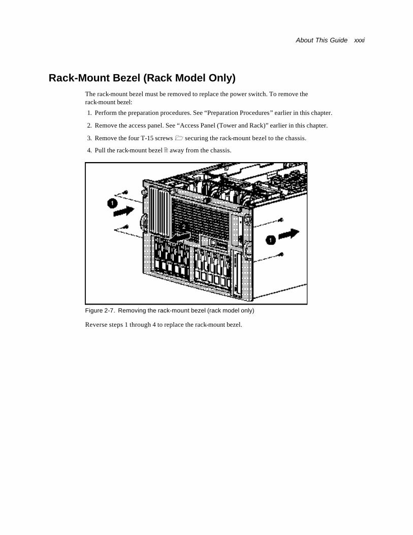
Rack-Mount Bezel (Rack Model Only) The rack-mount bezel must be removed to replace the power switch. To remove the rack-mount bezel:
1. Perform the preparation procedures. See “Preparation Procedures” earlier in this chapter.
2. Remove the access panel. See “Access Panel (Tower and Rack)” earlier in this chapter.
3. Remove the four T-15 screws 1 securing the rack-mount bezel to the chassis.
4. Pull the rack-mount bezel 2 away from the chassis.
Figure 2-7. Removing the rack-mount bezel (rack model only)
Reverse steps 1 through 4 to replace the rack-mount bezel.
xxxii Compaq ProLiant ML570 Maintenance and Service Guide
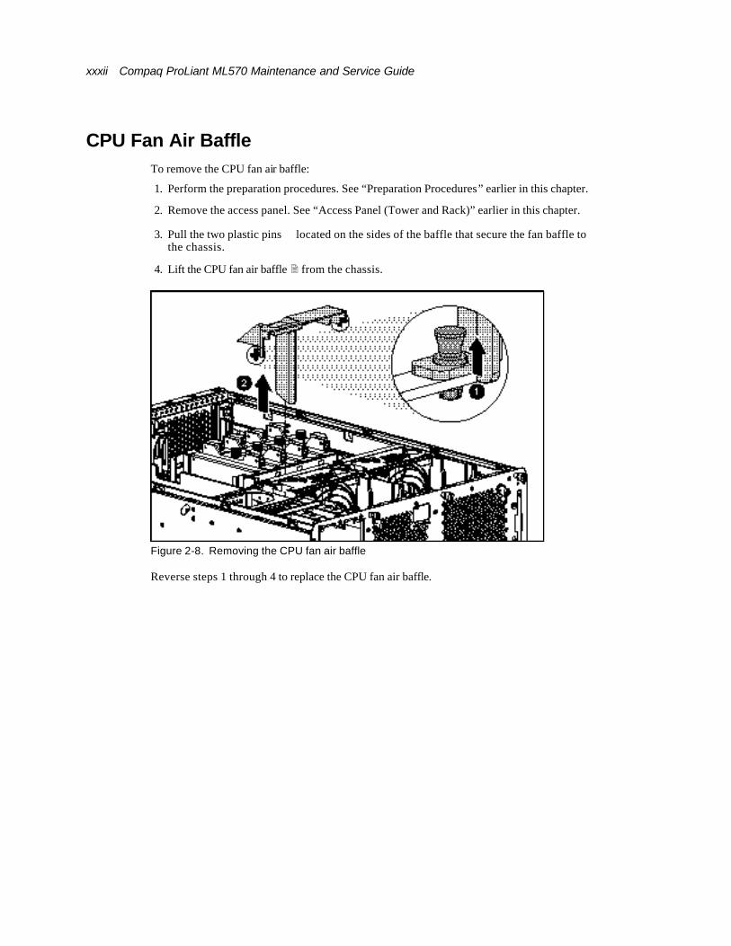
CPU Fan Air Baffle To remove the CPU fan air baffle:
1. Perform the preparation procedures. See “Preparation Procedures” earlier in this chapter.
2. Remove the access panel. See “Access Panel (Tower and Rack)” earlier in this chapter.
3. Pull the two plastic pins ⊇ located on the sides of the baffle that secure the fan baffle to the chassis.
4. Lift the CPU fan air baffle 2 from the chassis.
Figure 2-8. Removing the CPU fan air baffle
Reverse steps 1 through 4 to replace the CPU fan air baffle.

About This Guide xxxiii
Fans The ProLiant ML570 server ships standard with two hot-plug system fans (one CPU and one I/O) and three redundant, hot-plug drive fans. The two system fan baskets are designed to allow for a redundant hot-plug fan in each basket. Figure 2-9 and Table 2-4 show the location of all fans in the ProLiant ML570 server, including the fan name and primary function.
NOTE: Fans may continue to spin after a temporary failure occurs. Replace failed fans (amber LED) even if spinning continues.
Figure 2-9. Hot-plug fan locations
Table 2-4 Hot-Plug Fan Locations
Fan Name Primary Function Area Cooled
1 Hot-plug system fan Primary CPU fan Processors
2 Hot-plug system fan Redundant CPU fan
Processors
3 Hot-plug system fan Primary I/O fan System board
4 Hot-plug system fan Redundant I/O fan System board
5, 6, 7 Hot-plug hard drive fan
Drive fans Hard drives
Note: An amber fan LED indicates fan failure. A green fan LED indicates that the fan is working properly. See “Hot-Plug Fan LED Indicators” in Chapter 4 for more information.
xxxiv Compaq ProLiant ML570 Maintenance and Service Guide
Hot-Plug System Fans
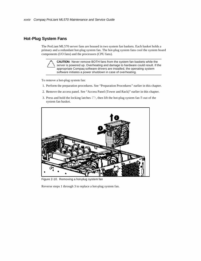
The ProLiant ML570 server fans are housed in two system fan baskets. Each basket holds a primary and a redundant hot-plug system fan. The hot-plug system fans cool the system board components (I/O fans) and the processors (CPU fans).
CAUTION: Never remove BOTH fans from the system fan baskets while the server is powered up. Overheating and damage to hardware could result. If the appropriate Compaq software drivers are installed, the operating system software initiates a power shutdown in case of overheating.
To remove a hot-plug system fan:
1. Perform the preparation procedures. See “Preparation Procedures” earlier in this chapter.
2. Remove the access panel. See “Access Panel (Tower and Rack)” earlier in this chapter.
3. Press and hold the locking latches 1, then lift the hot-plug system fan 2 out of the system fan basket.
Figure 2-10. Removing a hot-plug system fan
Reverse steps 1 through 3 to replace a hot-plug system fan.
About This Guide xxxv
System Fan Basket
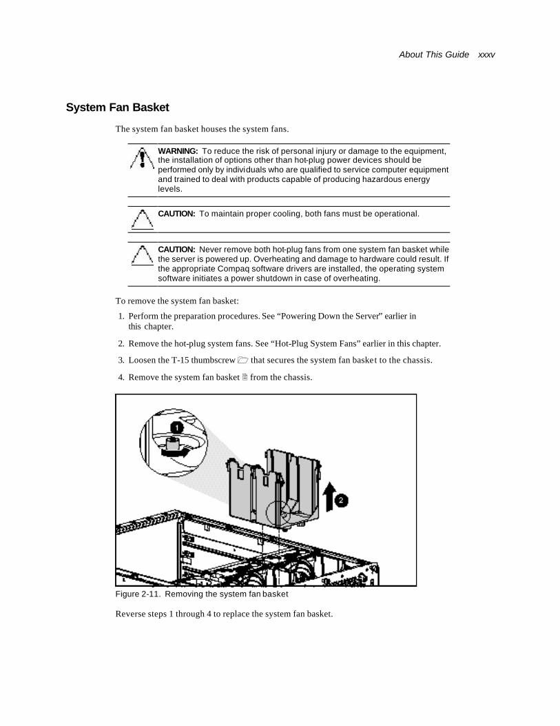
The system fan basket houses the system fans.
WARNING: To reduce the risk of personal injury or damage to the equipment, the installation of options other than hot-plug power devices should be performed only by individuals who are qualified to service computer equipment and trained to deal with products capable of producing hazardous energy levels.
CAUTION: To maintain proper cooling, both fans must be operational.
CAUTION: Never remove both hot-plug fans from one system fan basket while the server is powered up. Overheating and damage to hardware could result. If the appropriate Compaq software drivers are installed, the operating system software initiates a power shutdown in case of overheating.
To remove the system fan basket:
1. Perform the preparation procedures. See “Powering Down the Server” earlier in this chapter.
2. Remove the hot-plug system fans. See “Hot-Plug System Fans” earlier in this chapter.
3. Loosen the T-15 thumbscrew 1 that secures the system fan basket to the chassis.
4. Remove the system fan basket 2 from the chassis.
Figure 2-11. Removing the system fan basket
Reverse steps 1 through 4 to replace the system fan basket.
xxxvi Compaq ProLiant ML570 Maintenance and Service Guide
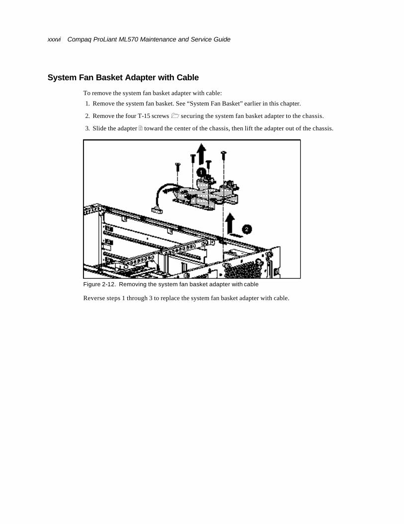
System Fan Basket Adapter with Cable
To remove the system fan basket adapter with cable:
1. Remove the system fan basket. See “System Fan Basket” earlier in this chapter.
2. Remove the four T-15 screws 1 securing the system fan basket adapter to the chassis.
3. Slide the adapter 2 toward the center of the chassis, then lift the adapter out of the chassis.
Figure 2-12. Removing the system fan basket adapter with cable
Reverse steps 1 through 3 to replace the system fan basket adapter with cable.
About This Guide xxxvii
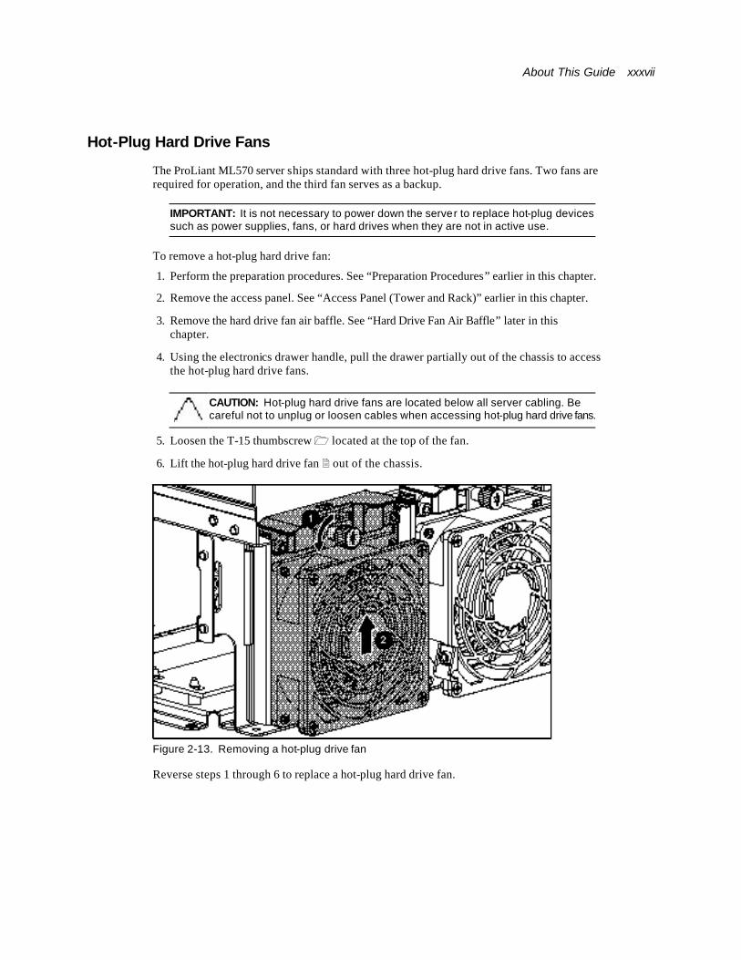
Hot-Plug Hard Drive Fans
The ProLiant ML570 server ships standard with three hot-plug hard drive fans. Two fans are required for operation, and the third fan serves as a backup.
IMPORTANT: It is not necessary to power down the server to replace hot-plug devices such as power supplies, fans, or hard drives when they are not in active use.
To remove a hot-plug hard drive fan:
1. Perform the preparation procedures. See “Preparation Procedures” earlier in this chapter.
2. Remove the access panel. See “Access Panel (Tower and Rack)” earlier in this chapter.
3. Remove the hard drive fan air baffle. See “Hard Drive Fan Air Baffle” later in this chapter.
4. Using the electronics drawer handle, pull the drawer partially out of the chassis to access the hot-plug hard drive fans.
CAUTION: Hot-plug hard drive fans are located below all server cabling. Be careful not to unplug or loosen cables when accessing hot-plug hard drive fans.
5. Loosen the T-15 thumbscrew 1 located at the top of the fan.
6. Lift the hot-plug hard drive fan 2 out of the chassis.
Figure 2-13. Removing a hot-plug drive fan
Reverse steps 1 through 6 to replace a hot-plug hard drive fan.

xxxviii Compaq ProLiant ML570 Maintenance and Service Guide
Hard Drive Fan Cable and Cable Bracket
WARNING: To reduce the risk of personal injury or damage to the equipment, the installation of options other than hot-plug power devices should be performed only by individuals who are qualified in servicing computer equipment and trained to deal with products capable of producing hazardous energy levels.
To remove the hard drive fan cable and cable bracket:
1. Perform the preparation procedures. See “Preparation Procedures” earlier in this chapter.
2. Remove the hot-plug drive fans. See “Hot-Plug Hard Drive Fans” earlier in this chapter.
3. Remove the hard drive fan air baffle. See “Hard Drive Fan Air Baffle” later in this chapter.
4. Remove the T-10 screw 1 holding the hard drive fan cable bracket in place, then lift the hard drive fan cable bracket from the chassis.
5. Unplug the hard drive fan cable 2 from the power backplane board.
6. Remove the hard drive fan cable from the unit.
Figure 2-14. Removing the hard drive fan cable and cable bracket
Reverse steps 1 through 6 to replace the hard drive fan cable and cable bracket.

About This Guide xxxix
Hard Drive Fan Air Baffle To remove the hard drive fan air baffle:
1. Perform the preparation procedures. See “Preparation Procedures” earlier in this chapter.
2. Remove the access panel. See “Access Panel (Tower and Rack)” earlier in this chapter.
3. Remove both system fan baskets. See “System Fan Basket” earlier in this chapter.
4. Slide the electronics drawer partially out of the chassis. See “Electronics Drawer” later in this chapter.
5. Loosen the two thumbscrews ⊇ on the hard drive fan air baffle.
6. Slide the baffle ⊄ over the drive fans, then lift the hard drive fan air baffle away from the chassis.
Figure 2-15. Removing the hard drive fan air baffle
Reverse steps 1 through 6 to replace the hard drive fan air baffle.
xl Compaq ProLiant ML570 Maintenance and Service Guide
Removable Media Area and Mass Storage Devices
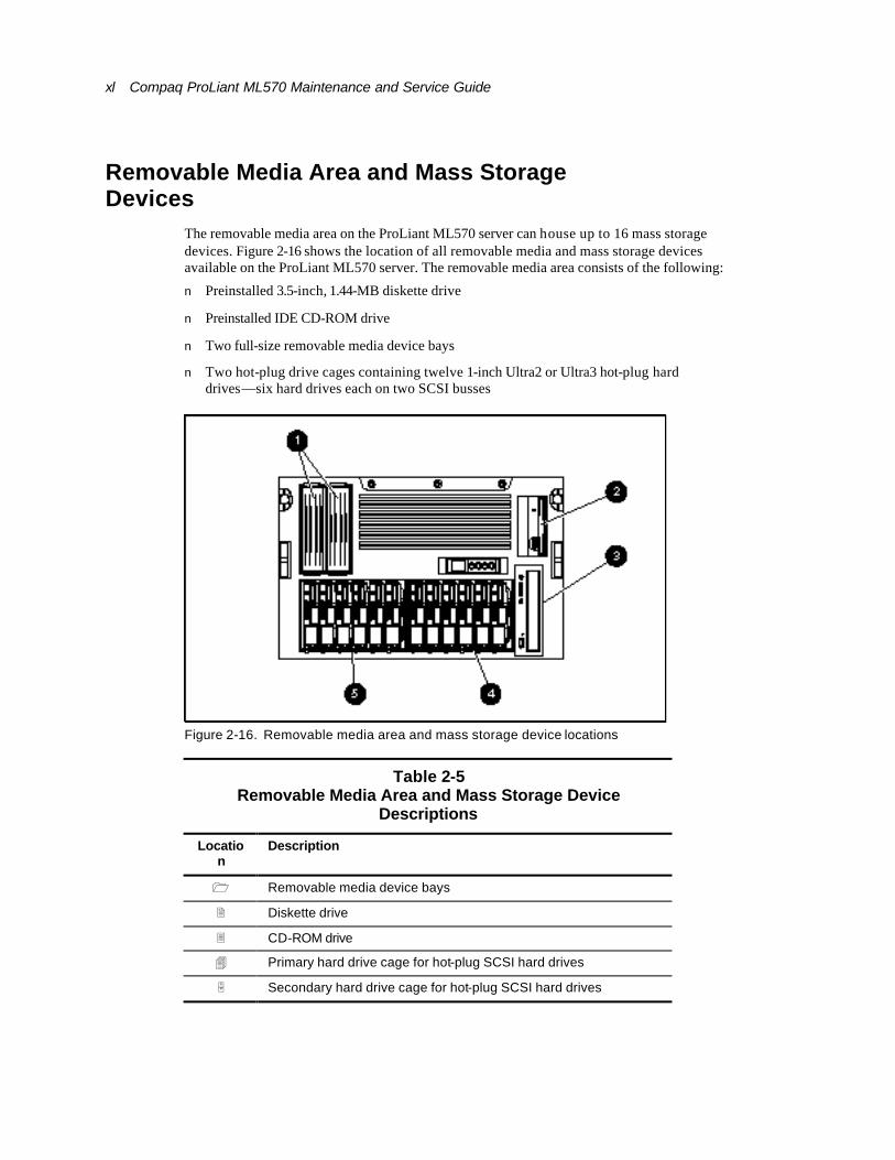
The removable media area on the ProLiant ML570 server can house up to 16 mass storage devices. Figure 2-16 shows the location of all removable media and mass storage devices available on the ProLiant ML570 server. The removable media area consists of the following:
n Preinstalled 3.5-inch, 1.44-MB diskette drive
n Preinstalled IDE CD-ROM drive
n Two full-size removable media device bays
n Two hot-plug drive cages containing twelve 1-inch Ultra2 or Ultra3 hot-plug hard drives—six hard drives each on two SCSI busses
Figure 2-16. Removable media area and mass storage device locations
Table 2-5 Removable Media Area and Mass Storage Device
Descriptions
Location
Description
1 Removable media device bays
2 Diskette drive
3 CD-ROM drive
4 Primary hard drive cage for hot-plug SCSI hard drives
5 Secondary hard drive cage for hot-plug SCSI hard drives
About This Guide xli
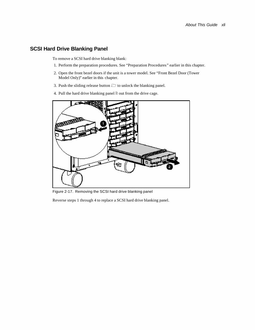
SCSI Hard Drive Blanking Panel
To remove a SCSI hard drive blanking blank:
1. Perform the preparation procedures. See “Preparation Procedures” earlier in this chapter.
2. Open the front bezel doors if the unit is a tower model. See “Front Bezel Door (Tower Model Only)” earlier in this chapter.
3. Push the sliding release button 1 to unlock the blanking panel.
4. Pull the hard drive blanking panel 2 out from the drive cage.
Figure 2-17. Removing the SCSI hard drive blanking panel
Reverse steps 1 through 4 to replace a SCSI hard drive blanking panel.
xlii Compaq ProLiant ML570 Maintenance and Service Guide
Hot-Plug Hard Drives
The following guidelines are to be noted when removing and replacing hot-plug hard drives:
n Never remove a hot-plug hard drive if the LED icon is green. If several drives are used, the system boot drive should be installed in the lowest-numbered bay.
n Never remove more than one hard drive at a time. If the server is set in an array configuration, and a hard drive is replaced, the controller uses data from the other drives in the array to reconstruct data on the replacement drive. If more than one hard drive is removed, a complete data set is not available to reconstruct data on the replacement drive(s).
n Never remove a working hard drive when another drive has been marked as failed by the controller. Permanent data loss occurs. Hard drives that have been failed by the controller are indicated by the amber drive failure LED icon on the drive tray.
n Never remove a drive while another drive is being rebuilt. A drive online LED icon flashes green when it is being rebuilt. A replaced drive is restored from data stored on the other drives.
About This Guide xliii
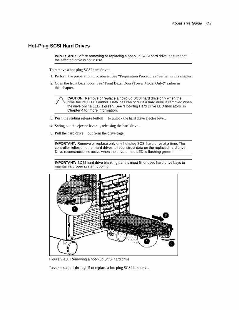
Hot-Plug SCSI Hard Drives
IMPORTANT: Before removing or replacing a hot-plug SCSI hard drive, ensure that the affected drive is not in use.
To remove a hot-plug SCSI hard drive:
1. Perform the preparation procedures. See “Preparation Procedures” earlier in this chapter.
2. Open the front bezel door. See “Front Bezel Door (Tower Model Only)” earlier in this chapter.
CAUTION: Remove or replace a hot-plug SCSI hard drive only when the drive failure LED is amber. Data loss can occur if a hard drive is removed when the drive online LED is green. See “Hot-Plug Hard Drive LED Indicators” in Chapter 4 for more information.
3. Push the sliding release button ⊇ to unlock the hard drive ejector lever.
4. Swing out the ejector lever ⊄, releasing the hard drive.
5. Pull the hard drive ⊂ out from the drive cage.
IMPORTANT: Remove or replace only one hot-plug SCSI hard drive at a time. The controller relies on other hard drives to reconstruct data on the replaced hard drive. Drive reconstruction is active when the drive online LED is flashing green.
IMPORTANT: SCSI hard drive blanking panels must fill unused hard drive bays to maintain a proper system cooling.
Figure 2-18. Removing a hot-plug SCSI hard drive
Reverse steps 1 through 5 to replace a hot-plug SCSI hard drive.
xliv Compaq ProLiant ML570 Maintenance and Service Guide
Hard Drive Cage with Backplane Board
The ProLiant ML570 server contains two hard drive cages. Each hard drive cage supports up to six hard drives.
CAUTION: If the ProLiant ML570 server is set up in an array configuration and an active hard drive is replaced while the system is powered down, the following POST hard drive error message (1786) occurs when the system is powered up:
PRESS <F1> TO BOOT THE SYSTEM AND REBUILD THE REPLACED DRIVE, OR PRESS <F2> TO BOOT THE SYSTEM WITHOUT REBUILDING THE DRIVE(S).
Pressing F2 causes permanent data loss to the logical hard drive. F2 should be pressed only when all of the hard drives were replaced or when complete data loss is desired.
NOTE: When a hard drive configured for fault tolerance is replaced, the replacement hard drive automatically begins reconstruction. Drive reconstruction is active when the drive online LED is flashing green.
To remove the hard drive cage with backplane board:
1. Perform the preparation procedures. See “Preparation Procedures” earlier in this chapter.
2. Remove the access panel. See “Access Panel (Tower and Rack)” earlier in this chapter.
3. Remove all hard drives from the bays of the cage to be removed. See “Hot-Plug SCSI Hard Drives” earlier in this chapter.
4. Remove the hard drive fan air baffle. See “Hard Drive Fan Air Baffle” earlier in this chapter.
About This Guide xlv
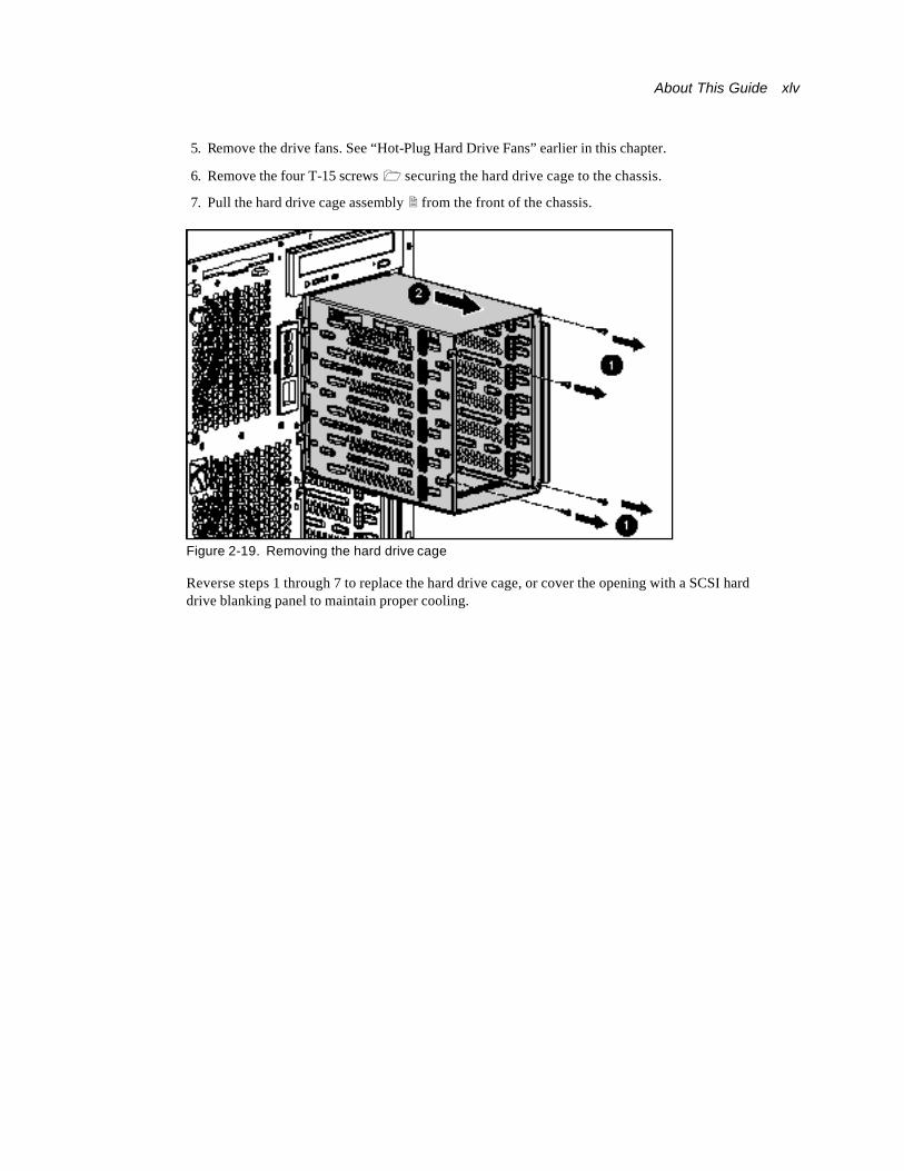
5. Remove the drive fans. See “Hot-Plug Hard Drive Fans” earlier in this chapter.
6. Remove the four T-15 screws 1 securing the hard drive cage to the chassis.
7. Pull the hard drive cage assembly 2 from the front of the chassis.
Figure 2-19. Removing the hard drive cage
Reverse steps 1 through 7 to replace the hard drive cage, or cover the opening with a SCSI hard drive blanking panel to maintain proper cooling.
xlvi Compaq ProLiant ML570 Maintenance and Service Guide
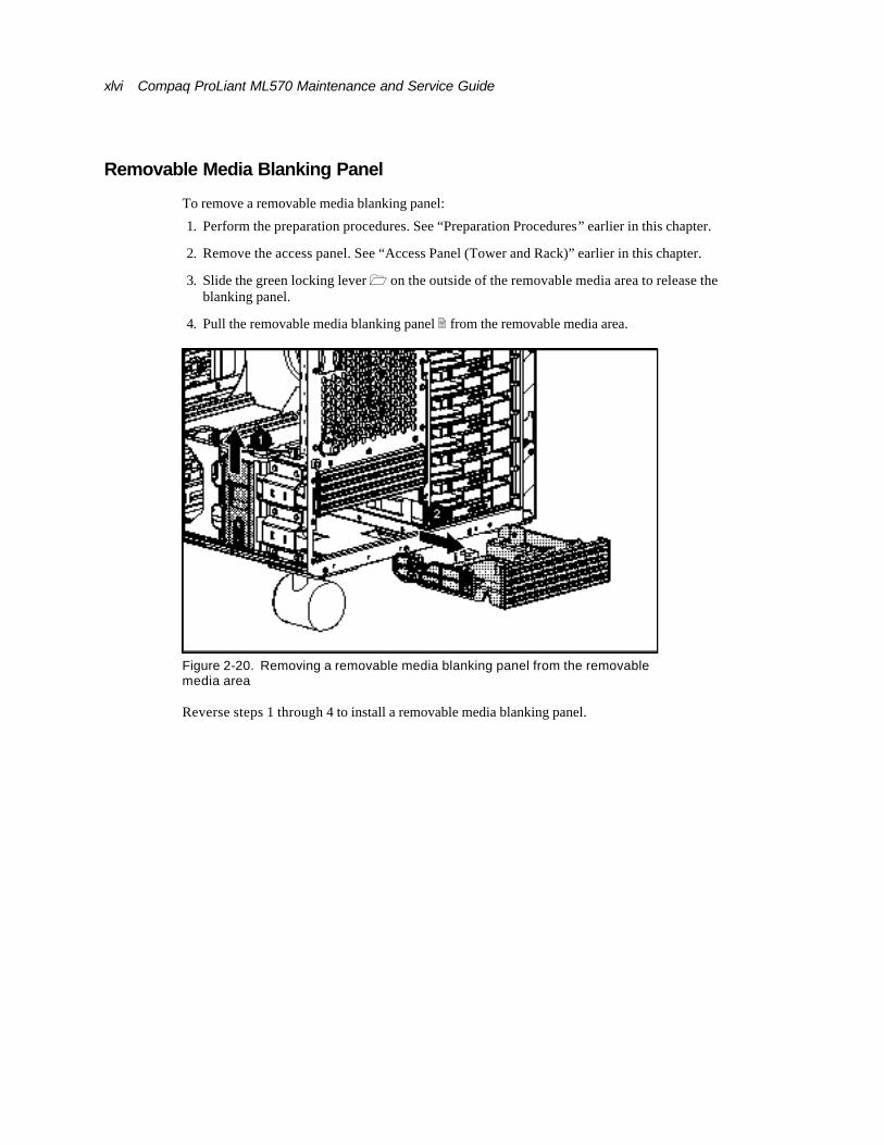
Removable Media Blanking Panel
To remove a removable media blanking panel:
1. Perform the preparation procedures. See “Preparation Procedures” earlier in this chapter.
2. Remove the access panel. See “Access Panel (Tower and Rack)” earlier in this chapter.
3. Slide the green locking lever 1 on the outside of the removable media area to release the blanking panel.
4. Pull the removable media blanking panel 2 from the removable media area.
Figure 2-20. Removing a removable media blanking panel from the removable media area
Reverse steps 1 through 4 to install a removable media blanking panel.
About This Guide xlvii
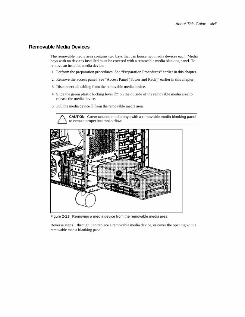
Removable Media Devices
The removable media area contains two bays that can house two media devices each. Media bays with no devices installed must be covered with a removable media blanking panel. To remove an installed media device:
1. Perform the preparation procedures. See “Preparation Procedures” earlier in this chapter.
2. Remove the access panel. See “Access Panel (Tower and Rack)” earlier in this chapter.
3. Disconnect all cabling from the removable media device.
4. Slide the green plastic locking lever 1 on the outside of the removable media area to release the media device.
5. Pull the media device 2 from the removable media area.
CAUTION: Cover unused media bays with a removable media blanking panel to ensure proper internal airflow.
Figure 2-21. Removing a media device from the removable media area
Reverse steps 1 through 5 to replace a removable media device, or cover the opening with a removable media blanking panel.
xlviii Compaq ProLiant ML570 Maintenance and Service Guide
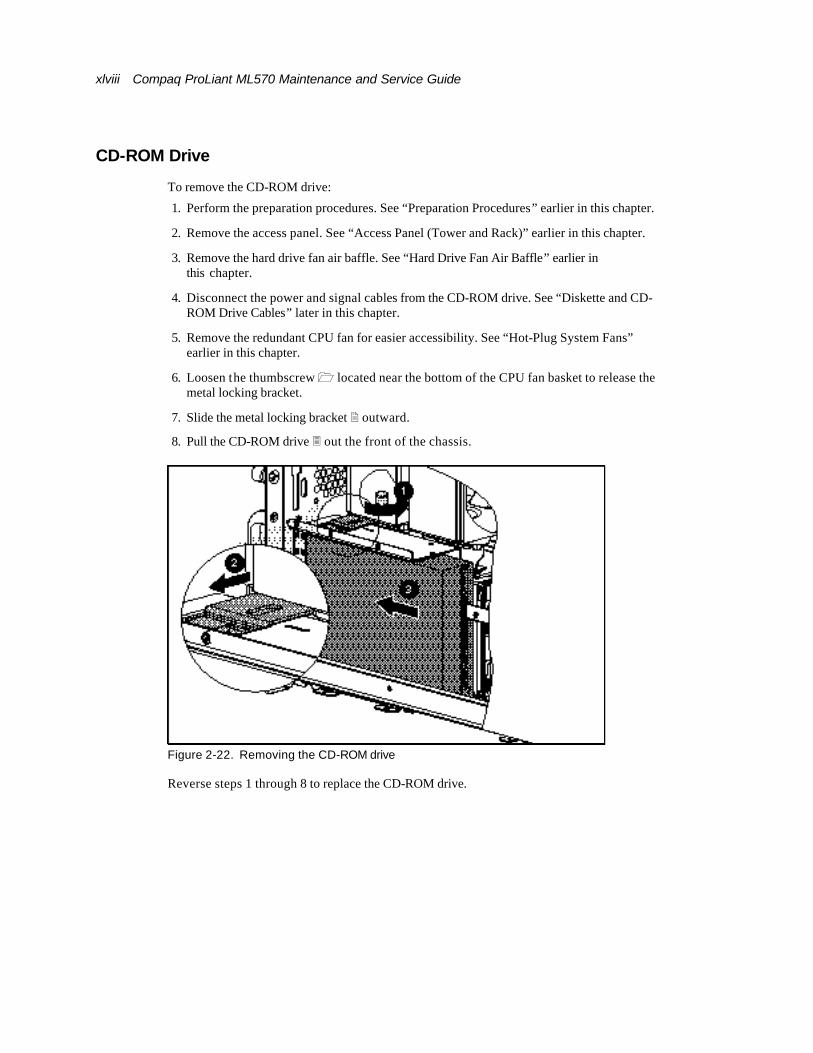
CD-ROM Drive
To remove the CD-ROM drive:
1. Perform the preparation procedures. See “Preparation Procedures” earlier in this chapter.
2. Remove the access panel. See “Access Panel (Tower and Rack)” earlier in this chapter.
3. Remove the hard drive fan air baffle. See “Hard Drive Fan Air Baffle” earlier in this chapter.
4. Disconnect the power and signal cables from the CD-ROM drive. See “Diskette and CD-ROM Drive Cables” later in this chapter.
5. Remove the redundant CPU fan for easier accessibility. See “Hot-Plug System Fans” earlier in this chapter.
6. Loosen the thumbscrew 1 located near the bottom of the CPU fan basket to release the metal locking bracket.
7. Slide the metal locking bracket 2 outward.
8. Pull the CD-ROM drive 3 out the front of the chassis.
Figure 2-22. Removing the CD-ROM drive
Reverse steps 1 through 8 to replace the CD-ROM drive.
About This Guide xlix
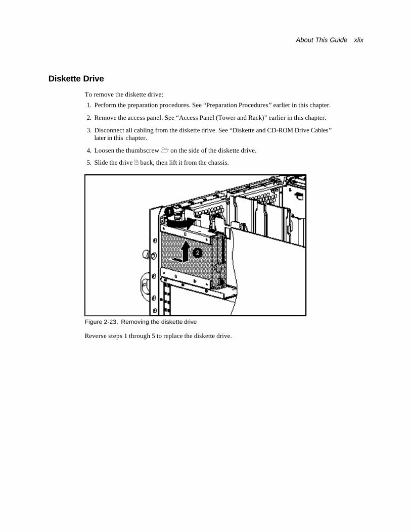
Diskette Drive
To remove the diskette drive:
1. Perform the preparation procedures. See “Preparation Procedures” earlier in this chapter.
2. Remove the access panel. See “Access Panel (Tower and Rack)” earlier in this chapter.
3. Disconnect all cabling from the diskette drive. See “Diskette and CD-ROM Drive Cables” later in this chapter.
4. Loosen the thumbscrew 1 on the side of the diskette drive.
5. Slide the drive 2 back, then lift it from the chassis.
Figure 2-23. Removing the diskette drive
Reverse steps 1 through 5 to replace the diskette drive.
l Compaq ProLiant ML570 Maintenance and Service Guide
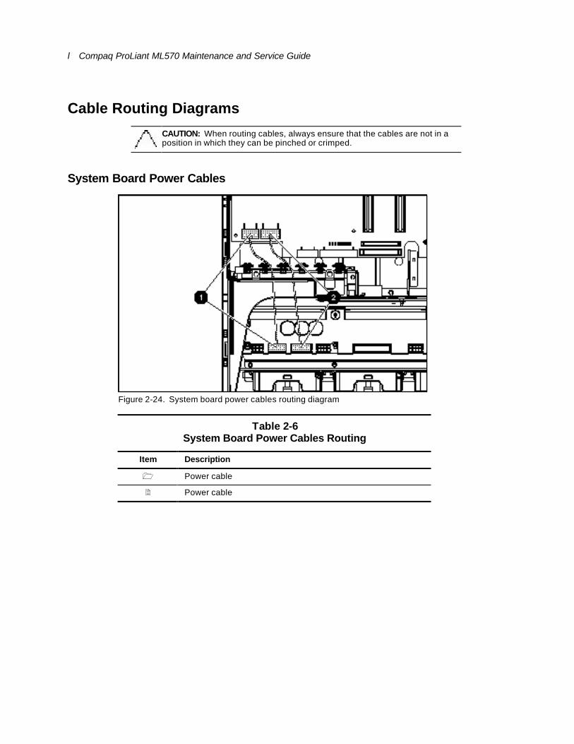
Cable Routing Diagrams
CAUTION: When routing cables, always ensure that the cables are not in a position in which they can be pinched or crimped.
System Board Power Cables
Figure 2-24. System board power cables routing diagram
Table 2-6 System Board Power Cables Routing
Item Description
1 Power cable
2 Power cable
About This Guide li
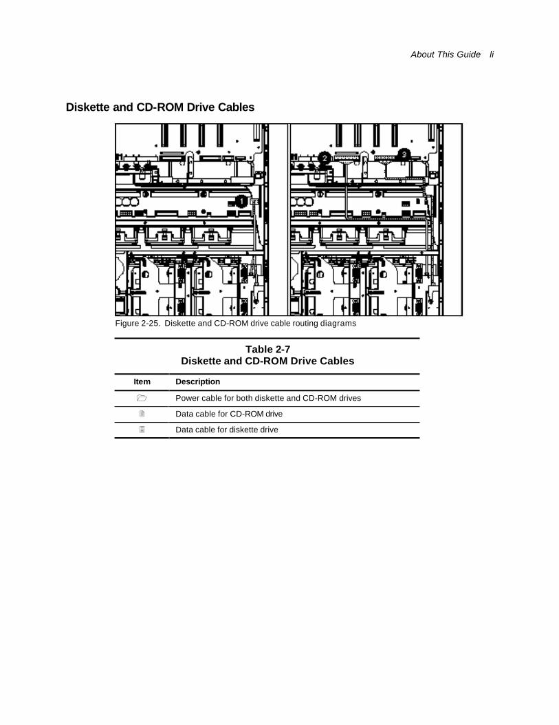
Diskette and CD-ROM Drive Cables
Figure 2-25. Diskette and CD-ROM drive cable routing diagrams
Table 2-7 Diskette and CD-ROM Drive Cables
Item Description
1 Power cable for both diskette and CD-ROM drives
2 Data cable for CD-ROM drive
3 Data cable for diskette drive
lii Compaq ProLiant ML570 Maintenance and Service Guide
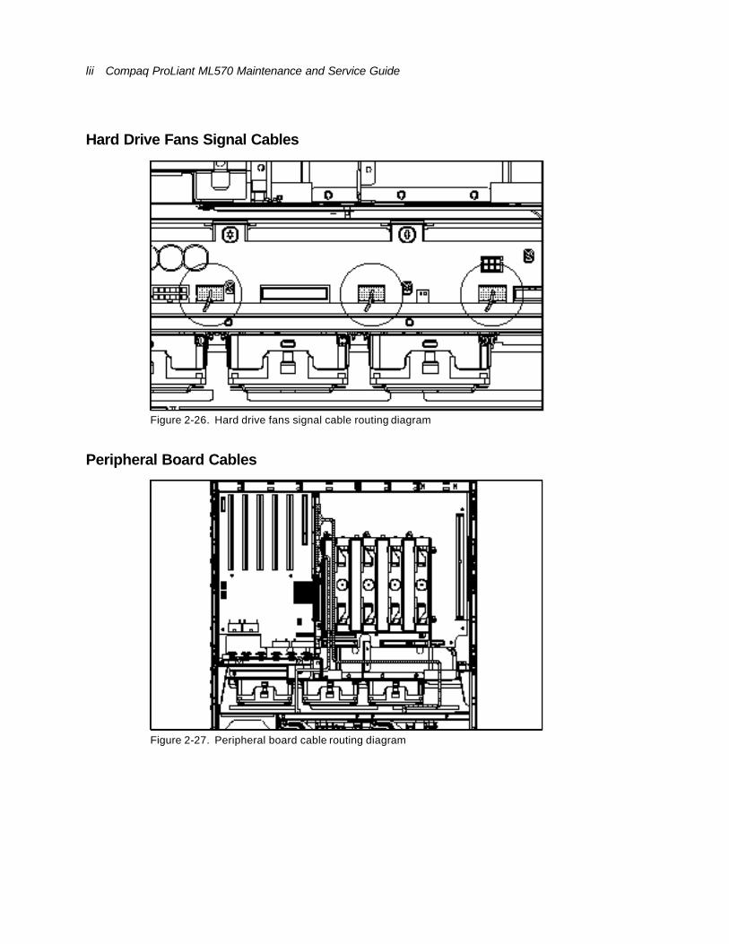
Hard Drive Fans Signal Cables
Figure 2-26. Hard drive fans signal cable routing diagram
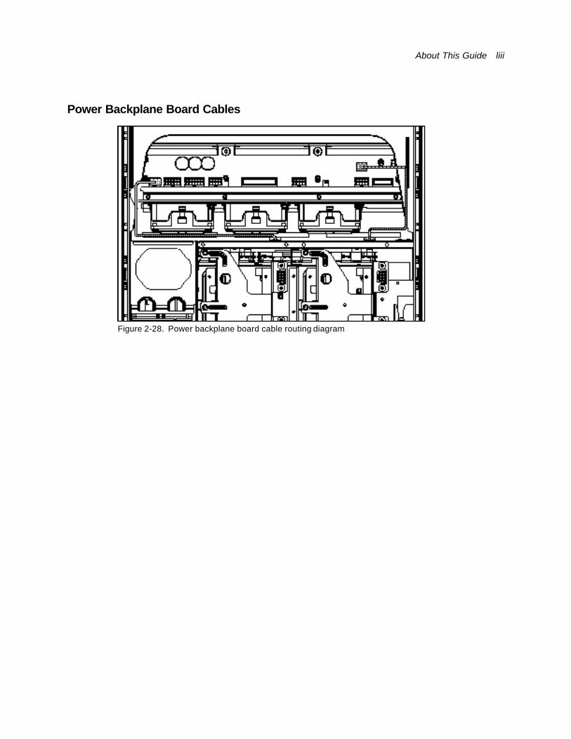
Peripheral Board Cables
Figure 2-27. Peripheral board cable routing diagram
About This Guide liii
Power Backplane Board Cables
Figure 2-28. Power backplane board cable routing diagram
liv Compaq ProLiant ML570 Maintenance and Service Guide
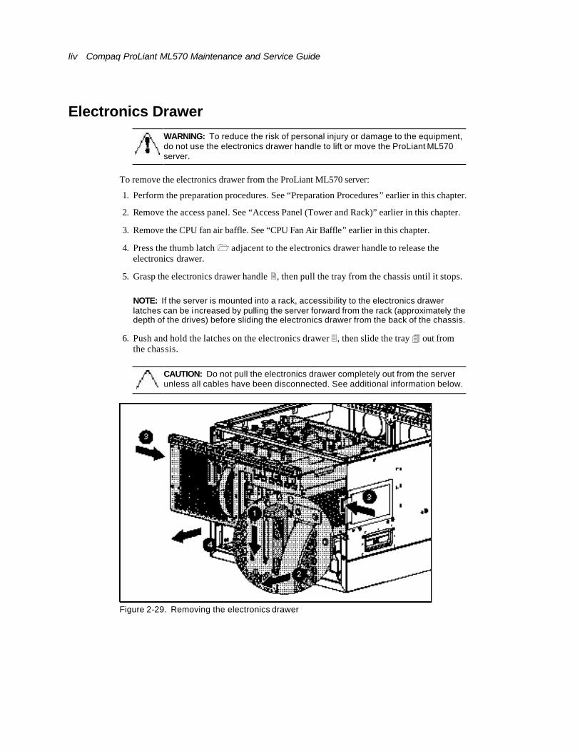
Electronics Drawer
WARNING: To reduce the risk of personal injury or damage to the equipment, do not use the electronics drawer handle to lift or move the ProLiant ML570 server.
To remove the electronics drawer from the ProLiant ML570 server:
1. Perform the preparation procedures. See “Preparation Procedures” earlier in this chapter.
2. Remove the access panel. See “Access Panel (Tower and Rack)” earlier in this chapter.
3. Remove the CPU fan air baffle. See “CPU Fan Air Baffle” earlier in this chapter.
4. Press the thumb latch 1 adjacent to the electronics drawer handle to release the electronics drawer.
5. Grasp the electronics drawer handle 2, then pull the tray from the chassis until it stops.
NOTE: If the server is mounted into a rack, accessibility to the electronics drawer latches can be increased by pulling the server forward from the rack (approximately the depth of the drives) before sliding the electronics drawer from the back of the chassis.
6. Push and hold the latches on the electronics drawer 3, then slide the tray 4 out from the chassis.
CAUTION: Do not pull the electronics drawer completely out from the server unless all cables have been disconnected. See additional information below.
Figure 2-29. Removing the electronics drawer
About This Guide lv
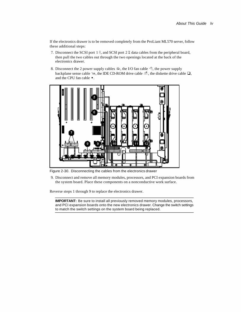
If the electronics drawer is to be removed completely from the ProLiant ML570 server, follow these additional steps:
7. Disconnect the SCSI port 1 5, and SCSI port 2 6 data cables from the peripheral board, then pull the two cables out through the two openings located at the back of the electronics drawer.
8. Disconnect the 2 power supply cables 7, the I/O fan cable 8, the power supply backplane sense cable 9, the IDE CD-ROM drive cable -, the diskette drive cable q, and the CPU fan cable w.
Figure 2-30. Disconnecting the cables from the electronics drawer
9. Disconnect and remove all memory modules, processors, and PCI expansion boards from the system board. Place these components on a nonconductive work surface.
Reverse steps 1 through 9 to replace the electronics drawer.
IMPORTANT: Be sure to install all previously removed memory modules, processors, and PCI expansion boards onto the new electronics drawer. Change the switch settings to match the switch settings on the system board being replaced.
lvi Compaq ProLiant ML570 Maintenance and Service Guide
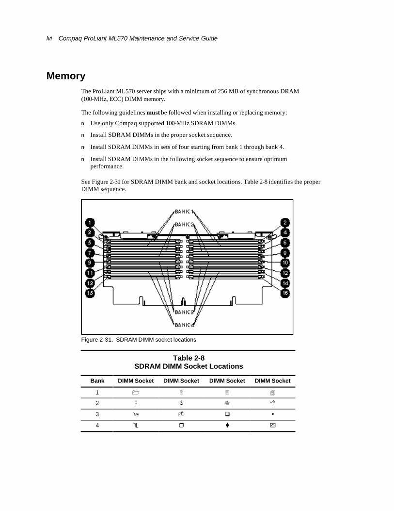
Memory The ProLiant ML570 server ships with a minimum of 256 MB of synchronous DRAM (100-MHz, ECC) DIMM memory.
The following guidelines must be followed when installing or replacing memory:
n Use only Compaq supported 100-MHz SDRAM DIMMs.
n Install SDRAM DIMMs in the proper socket sequence.
n Install SDRAM DIMMs in sets of four starting from bank 1 through bank 4.
n Install SDRAM DIMMs in the following socket sequence to ensure optimum performance.
See Figure 2-31 for SDRAM DIMM bank and socket locations. Table 2-8 identifies the proper DIMM sequence.
Figure 2-31. SDRAM DIMM socket locations
Table 2-8 SDRAM DIMM Socket Locations
Bank DIMM Socket DIMM Socket DIMM Socket DIMM Socket
1 1 2 3 4
2 5 6 7 8
3 9 - q w
4 e r t y

About This Guide lvii
Memory Expansion Board
To remove the memory expansion board:
1. Perform the preparation procedures. See “Preparation Procedures” earlier in this chapter.
2. Remove the access panel. See “Access Panel (Tower and Rack)” earlier in this chapter.
3. Push in on both sliding locks 1 to release the ejector levers.
4. Pull the ejector levers 2 up to loosen the memory expansion board from the system board slot.
5. Lift the memory expansion board 3 from the system board slot.
Figure 2-32. Removing the memory expansion board
Reverse steps 1 through 5 to replace the memory expansion board.

lviii Compaq ProLiant ML570 Maintenance and Service Guide
Dual Inline Memory Module (DIMM) Combinations
Table 2-9 Dual Inline Memory Module (DIMM) Combinations
Total Memory
Socket 1
Socket 2
Socket 3
Socket 4
Socket 5
Socket 6
Socket 7
Socket 8
256 MB 64 MB 64 MB 64 MB 64 MB
768 MB 64 MB 64 MB 64 MB 64 MB 128 MB 128 MB 128 MB 128 MB
512 MB 128 MB 128 MB 128 MB 128 MB
1 GB 256 MB 256 MB 256 MB 256 MB
2 GB 256 MB 256 MB 256 MB 256 MB 256 MB 256 MB 256 MB 256 MB
2 GB 512 MB 512 MB 512 MB 512 MB
3 GB 256 MB 256 MB 512 MB 512 MB 256 MB 256 MB 512 MB 512 MB
4 GB 512 MB 512 MB 512 MB 512 MB 512 MB 512 MB 512 MB 512 MB
Note: These are examples only. Because the board has 16 sockets, more DIMM combinations can be added as long as the DIMMs are installed in sets of four modules per bank. DIMMs must be identical in each bank .
About This Guide lix
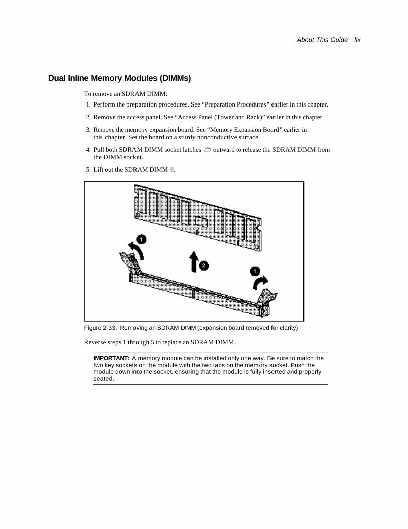
Dual Inline Memory Modules (DIMMs)
To remove an SDRAM DIMM:
1. Perform the preparation procedures. See “Preparation Procedures” earlier in this chapter.
2. Remove the access panel. See “Access Panel (Tower and Rack)” earlier in this chapter.
3. Remove the memo ry expansion board. See “Memory Expansion Board” earlier in this chapter. Set the board on a sturdy nonconductive surface.
4. Pull both SDRAM DIMM socket latches 1 outward to release the SDRAM DIMM from the DIMM socket.
5. Lift out the SDRAM DIMM 2.
Figure 2-33. Removing an SDRAM DIMM (expansion board removed for clarity)
Reverse steps 1 through 5 to replace an SDRAM DIMM.
IMPORTANT: A memory module can be installed only one way. Be sure to match the two key sockets on the module with the two tabs on the memory socket. Push the module down into the socket, ensuring that the module is fully inserted and properly seated.

lx Compaq ProLiant ML570 Maintenance and Service Guide
Peripheral Board (Non-Hot-Pluggable) To remove the peripheral board (non-hot-pluggable):
1. Perform the preparation procedures. See “Preparation Procedures” earlier in this chapter.
2. Remove the access panel. See “Access Panel (Tower and Rack)” earlier in this chapter.
3. Unplug all power supplies. See “Hot-Plug Power Supplies” later in this chapter.
CAUTION: Power supplies must be unplugged when servicing the peripheral board.
4. Remove data and signal cables from the board. See “Peripheral Board Cables” earlier in this chapter.
5. Loosen the two T-15 chassis screws 1 securing the peripheral board to the chassis.
6. Pull the ejectors levers 2 up to loosen the peripheral board from the expansion slot.
7. Pull the peripheral board 3 from the system board expansion slot.
CAUTION: Rotating the peripheral board release levers a full 90 degrees can cause the levers to break.
Figure 2-34. Removing the peripheral board (non-hot-pluggable)
Reverse steps 1 through 7 to replace the peripheral board (non-hot-pluggable).
About This Guide lxi
I/O Expansion Boards
Hot-Pluggable I/O Expansion Boards
CAUTION: Do not attempt a PCI Hot Plug procedure if your operating system does not provide PCI Hot Plug support, or i f you do not have the appropriate device drivers installed. Failure to take these precautions causes system shutdown and risks data integrity.
CAUTION: To avoid critical errors, do not open the slot release lever if the green power LED is on or blinking. Use the PCI Hot Plug button or the software application to turn off power to the slot.
Use either the PCI Hot Plug button on the server or your operating system PCI Hot Plug utility to control the PCI Hot Plug slots.
n The PCI Hot Plug button and the PCI Hot Plug utility allow you to power on or power off a hot-pluggable I/O expansion board slot. However, the PCI Hot Plug Button allows direct access at each hot-pluggable expansion slot.
n PCI Hot Plug software support for each operating system is available online. For more information, see the “PCI Hot Plug Important Facts” section in the online PCI Hot Plug Administration Guide on the Systems Reference Library CD.
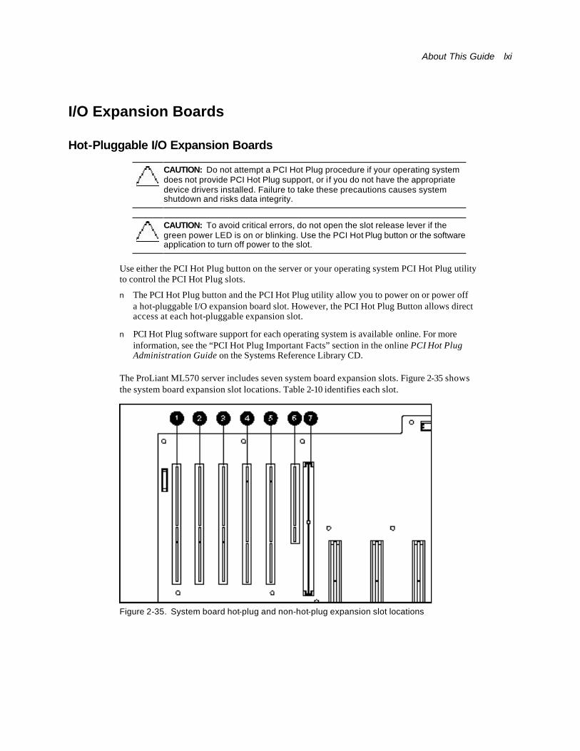
The ProLiant ML570 server includes seven system board expansion slots. Figure 2-35 shows the system board expansion slot locations. Table 2-10 identifies each slot.
Figure 2-35. System board hot-plug and non-hot-plug expansion slot locations

lxii Compaq ProLiant ML570 Maintenance and Service Guide
Table 2-10 System Board Expansion Slots
Slot Description
1 PCI slot, 33-MHz/64-bit (non-hot-pluggable)
2 PCI slot, 33-MHz/64-bit
3 PCI slot, 33-MHz/64-bit
4 PCI slot, 66-MHz/64-bit
5 PCI slot, 66-MHz/64-bit
6 PCI slot, 33-MHz/64-bit (non-hot-pluggable)
7 Peripheral board slot (non-hot-pluggable)
PCI Hot Plug expansion slots are accessible using the PCI Hot Plug access door.
NOTE: The following procedure is for hot-pluggable I/O expansion boards. The board illustrated in Figure 2-38 is an example of an extended SCSI type I/O expansion board.
To remove a hot-pluggable I/O expansion board:
1. Unlock and open the PCI Hot Plug access door.
Figure 2-36. Opening the PCI Hot Plug access door
About This Guide lxiii
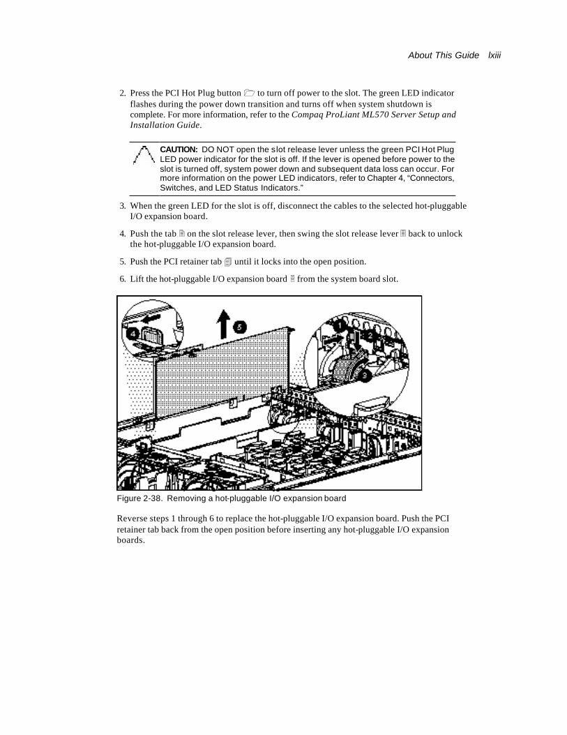
2. Press the PCI Hot Plug button 1 to turn off power to the slot. The green LED indicator flashes during the power down transition and turns off when system shutdown is complete. For more information, refer to the Compaq ProLiant ML570 Server Setup and Installation Guide.
CAUTION: DO NOT open the slot release lever unless the green PCI Hot Plug LED power indicator for the slot is off. If the lever is opened before power to the slot is turned off, system power down and subsequent data loss can occur. For more information on the power LED indicators, refer to Chapter 4, “Connectors, Switches, and LED Status Indicators.”
3. When the green LED for the slot is off, disconnect the cables to the selected hot-pluggable I/O expansion board.
4. Push the tab 2 on the slot release lever, then swing the slot release lever 3 back to unlock the hot-pluggable I/O expansion board.
5. Push the PCI retainer tab 4 until it locks into the open position.
6. Lift the hot-pluggable I/O expansion board 5 from the system board slot.
Figure 2-38. Removing a hot-pluggable I/O expansion board
Reverse steps 1 through 6 to replace the hot-pluggable I/O expansion board. Push the PCI retainer tab back from the open position before inserting any hot-pluggable I/O expansion boards.
lxiv Compaq ProLiant ML570 Maintenance and Service Guide
IMPORTANT: Installing a 33-MHz expansion board into either of the 66-MHz slots (4 and 5) decreases the bus speed in both slots to 33 MHz.
Non-Hot-Pluggable I/O Expansion Board
To remove a non-hot-pluggable I/O expansion board:
1. Perform the preparation procedures. See “Non-Hot-Pluggable Parts” earlier in this chapter.
2. Remove the access panel. See “Access Panel (Tower and Rack)” earlier in this chapter.
NOTE: The electronics drawer must be completely in or completely out of the chassis to remove a full-size expansion board.
3. Refer to steps 4 through 6 in “Hot-Pluggable I/O Expansion Board” earlier in this section.
About This Guide lxv
Compaq NC3123 Fast Ethernet NIC PCI 10/100 Wake on LAN (WOL) Controller
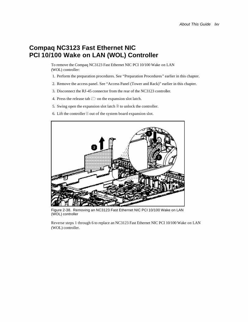
To remove the Compaq NC3123 Fast Ethernet NIC PCI 10/100 Wake on LAN (WOL) controller:
1. Perform the preparation procedures. See “Preparation Procedures” earlier in this chapter.
2. Remove the access panel. See “Access Panel (Tower and Rack)” earlier in this chapter.
3. Disconnect the RJ-45 connector from the rear of the NC3123 controller.
4. Press the release tab 1 on the expansion slot latch.
5. Swing open the expansion slot latch 2 to unlock the controller.
6. Lift the controller 3 out of the system board expansion slot.
Figure 2-38. Removing an NC3123 Fast Ethernet NIC PCI 10/100 Wake on LAN (WOL) controller
Reverse steps 1 through 6 to replace an NC3123 Fast Ethernet NIC PCI 10/100 Wake on LAN (WOL) controller.
lxvi Compaq ProLiant ML570 Maintenance and Service Guide
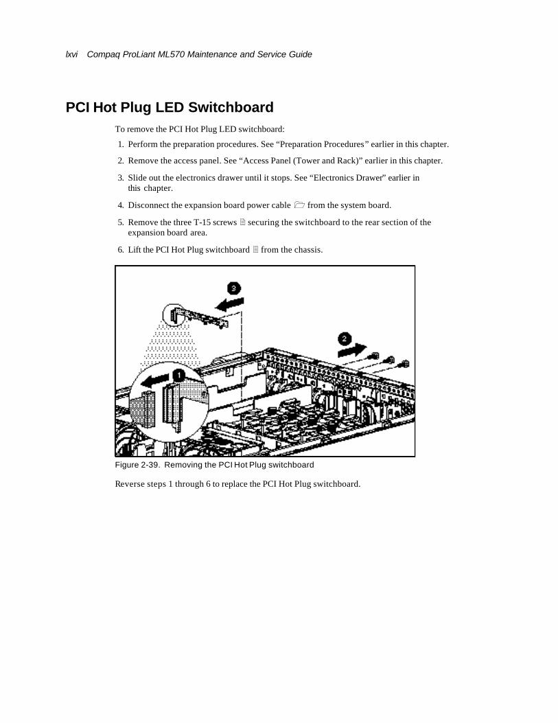
PCI Hot Plug LED Switchboard To remove the PCI Hot Plug LED switchboard:
1. Perform the preparation procedures. See “Preparation Procedures” earlier in this chapter.
2. Remove the access panel. See “Access Panel (Tower and Rack)” earlier in this chapter.
3. Slide out the electronics drawer until it stops. See “Electronics Drawer” earlier in this chapter.
4. Disconnect the expansion board power cable 1 from the system board.
5. Remove the three T-15 screws 2 securing the switchboard to the rear section of the expansion board area.
6. Lift the PCI Hot Plug switchboard 3 from the chassis.
Figure 2-39. Removing the PCI Hot Plug switchboard
Reverse steps 1 through 6 to replace the PCI Hot Plug switchboard.
About This Guide lxvii
Processors, Terminator Boards, and Processor Cage
Processors
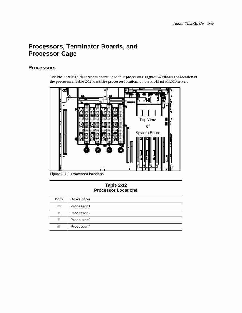
The ProLiant ML570 server supports up to four processors. Figure 2-40 shows the location of the processors. Table 2-12 identifies processor locations on the ProLiant ML570 server.
Figure 2-40. Processor locations
Table 2-12 Processor Locations
Item Description
1 Processor 1
2 Processor 2
3 Processor 3
4 Processor 4

lxviii Compaq ProLiant ML570 Maintenance and Service Guide
To remove a processor:
1. Perform the preparation procedures. See “Preparation Procedures” earlier in this chapter.
2. Remove the access panel. See “Access Panel (Tower and Rack)” earlier in this chapter.
3. Remove the CPU fan air baffle. See “CPU Fan Air Baffle” earlier in this chapter.
4. Loosen the thumbscrew 1 located on the top of the processor.
5. Pull up, then swing open the ejector levers 2 on both sides of the processor.
6. Lift the processor 3 from the slot.
Figure 2-42. Removing a processor
Reverse steps 1 through 6 to replace a processor.
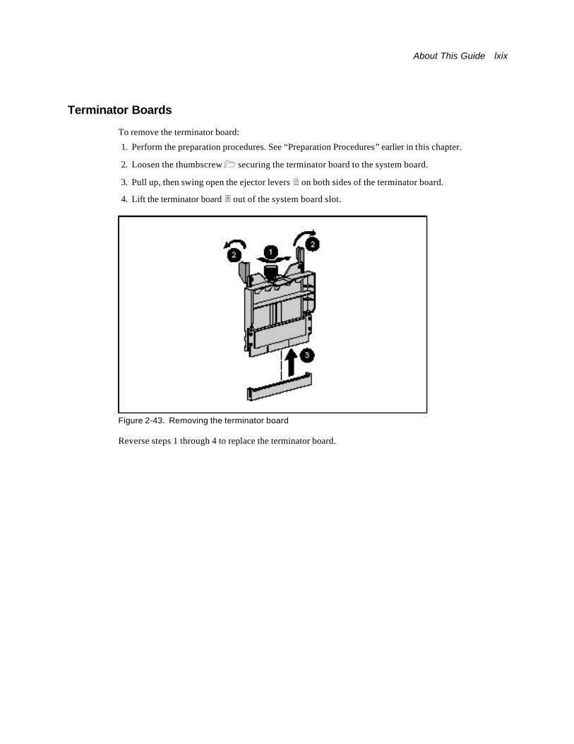
About This Guide lxix
Terminator Boards
To remove the terminator board:
1. Perform the preparation procedures. See “Preparation Procedures” earlier in this chapter.
2. Loosen the thumbscrew 1 securing the terminator board to the system board.
3. Pull up, then swing open the ejector levers 2 on both sides of the terminator board.
4. Lift the terminator board 3 out of the system board slot.
Figure 2-43. Removing the terminator board
Reverse steps 1 through 4 to replace the terminator board.
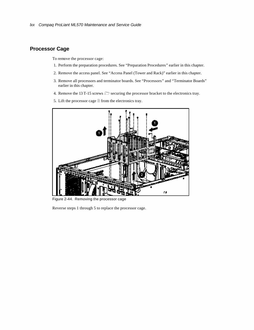
lxx Compaq ProLiant ML570 Maintenance and Service Guide
Processor Cage
To remove the processor cage:
1. Perform the preparation procedures. See “Preparation Procedures” earlier in this chapter.
2. Remove the access panel. See “Access Panel (Tower and Rack)” earlier in this chapter.
3. Remove all processors and terminator boards. See “Processors” and “Terminator Boards” earlier in this chapter.
4. Remove the 13 T-15 screws 1 securing the processor bracket to the electronics tray.
5. Lift the processor cage 2 from the electronics tray.
Figure 2-44. Removing the processor cage
Reverse steps 1 through 5 to replace the processor cage.
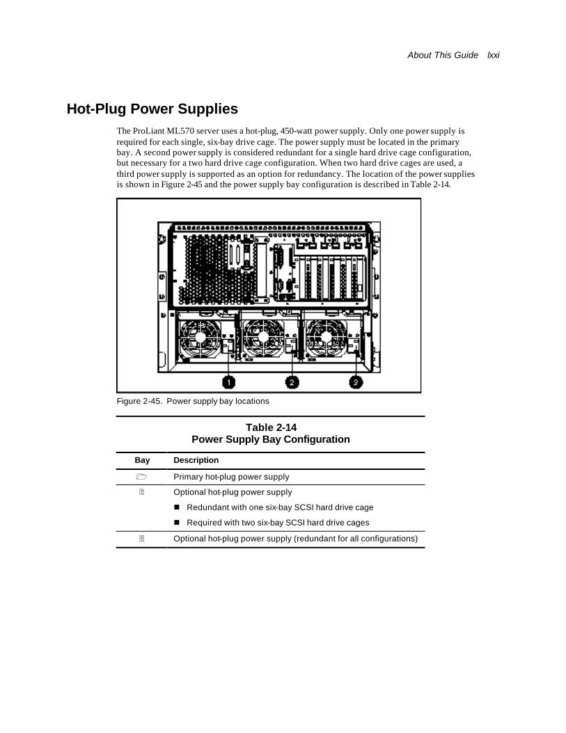
About This Guide lxxi
Hot-Plug Power Supplies The ProLiant ML570 server uses a hot-plug, 450-watt power supply. Only one power supply is required for each single, six-bay drive cage. The power supply must be located in the primary bay. A second power supply is considered redundant for a single hard drive cage configuration, but necessary for a two hard drive cage configuration. When two hard drive cages are used, a third power supply is supported as an option for redundancy. The location of the power supplies is shown in Figure 2-45 and the power supply bay configuration is described in Table 2-14.
Figure 2-45. Power supply bay locations
Table 2-14 Power Supply Bay Configuration
Bay Description
1 Primary hot-plug power supply
2 Optional hot-plug power supply
n Redundant with one six-bay SCSI hard drive cage
n Required with two six-bay SCSI hard drive cages
3 Optional hot-plug power supply (redundant for all configurations)
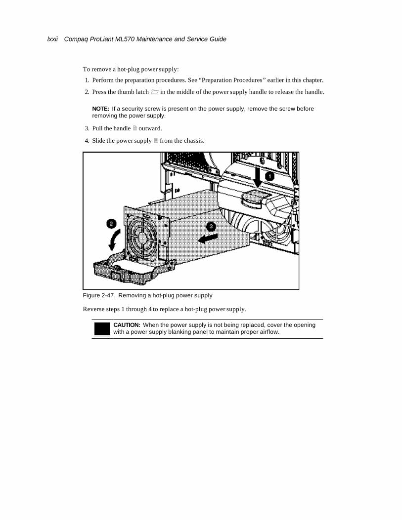
lxxii Compaq ProLiant ML570 Maintenance and Service Guide
To remove a hot-plug power supply:
1. Perform the preparation procedures. See “Preparation Procedures” earlier in this chapter.
2. Press the thumb latch 1 in the middle of the power supply handle to release the handle.
NOTE: If a security screw is present on the power supply, remove the screw before removing the power supply.
3. Pull the handle 2 outward.
4. Slide the power supply 3 from the chassis.
Figure 2-47. Removing a hot-plug power supply
Reverse steps 1 through 4 to replace a hot-plug power supply.
CAUTION: When the power supply is not being replaced, cover the opening with a power supply blanking panel to maintain proper airflow.
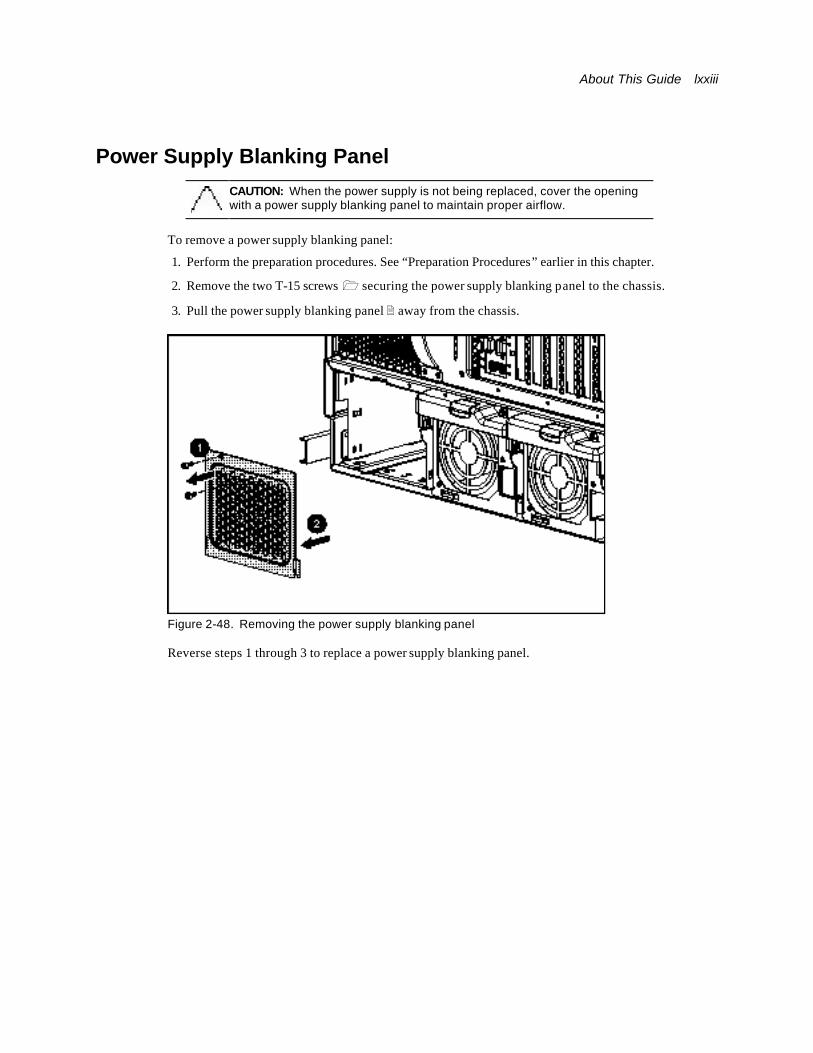
About This Guide lxxiii
Power Supply Blanking Panel
CAUTION: When the power supply is not being replaced, cover the opening with a power supply blanking panel to maintain proper airflow.
To remove a power supply blanking panel:
1. Perform the preparation procedures. See “Preparation Procedures” earlier in this chapter.
2. Remove the two T-15 screws 1 securing the power supply blanking panel to the chassis.
3. Pull the power supply blanking panel 2 away from the chassis.
Figure 2-48. Removing the power supply blanking panel
Reverse steps 1 through 3 to replace a power supply blanking panel.

lxxiv Compaq ProLiant ML570 Maintenance and Service Guide
Power Backplane Board To remove the power backplane board:
1. Perform the preparation procedures. See “Preparation Procedures” earlier in this chapter.
2. Remove the access panel. See “Access Panel (Tower and Rack)” earlier in this chapter.
3. Slide the electronics drawer partially out of the chassis. See “Electronics Drawer” earlier in this chapter.
4. Remove the hard drive fan air baffle. See “Hard Drive Fan Air Baffle” earlier in this chapter.
5. Disconnect all cables from the power backplane board. See “Cable Routing Diagrams ” earlier in this chapter.
6. Loosen the two T-15 thumbscrews 1.
7. Slide the power backplane board 2 toward the power supplies, then lift the power backplane board from the chassis.
Figure 2-49. Removing the power backplane board
Reverse steps 1 through 7 to replace the power backplane board.

About This Guide lxxv
Power On/Standby Switch and Cable Assembly
To remove the Power On/Standby switch and cable assembly:
1. Perform the preparation procedures. See “Preparation Procedures” earlier in this chapter.
2. Remove the access panel. See “Access Panel (Tower and Rack)” earlier in this chapter.
3. Remove the hard drive fan air baffle. See “Hard Drive Fan Air Baffle” earlier in this chapter.
4. Disconnect the power switch cable 1 from the power backplane board.
5. Press the tabs 2 inward on both sides of the switch.
NOTE: Compaq recommends pressing the tabs with a 4-mm flat-blade screwdriver.
6. With the tabs released, pull the switch and cable assembly 3 out the front of the bezel.
Figure 2-50. Removing the Power On/Standby switch and cable assembly
Reverse steps 1 through 6 to replace the Power On/Standby switch and cable assembly.
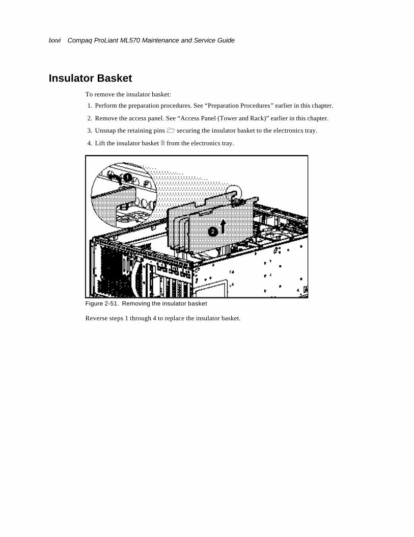
lxxvi Compaq ProLiant ML570 Maintenance and Service Guide
Insulator Basket To remove the insulator basket:
1. Perform the preparation procedures. See “Preparation Procedures” earlier in this chapter.
2. Remove the access panel. See “Access Panel (Tower and Rack)” earlier in this chapter.
3. Unsnap the retaining pins 1 securing the insulator basket to the electronics tray.
4. Lift the insulator basket 2 from the electronics tray.
Figure 2-51. Removing the insulator basket
Reverse steps 1 through 4 to replace the insulator basket.
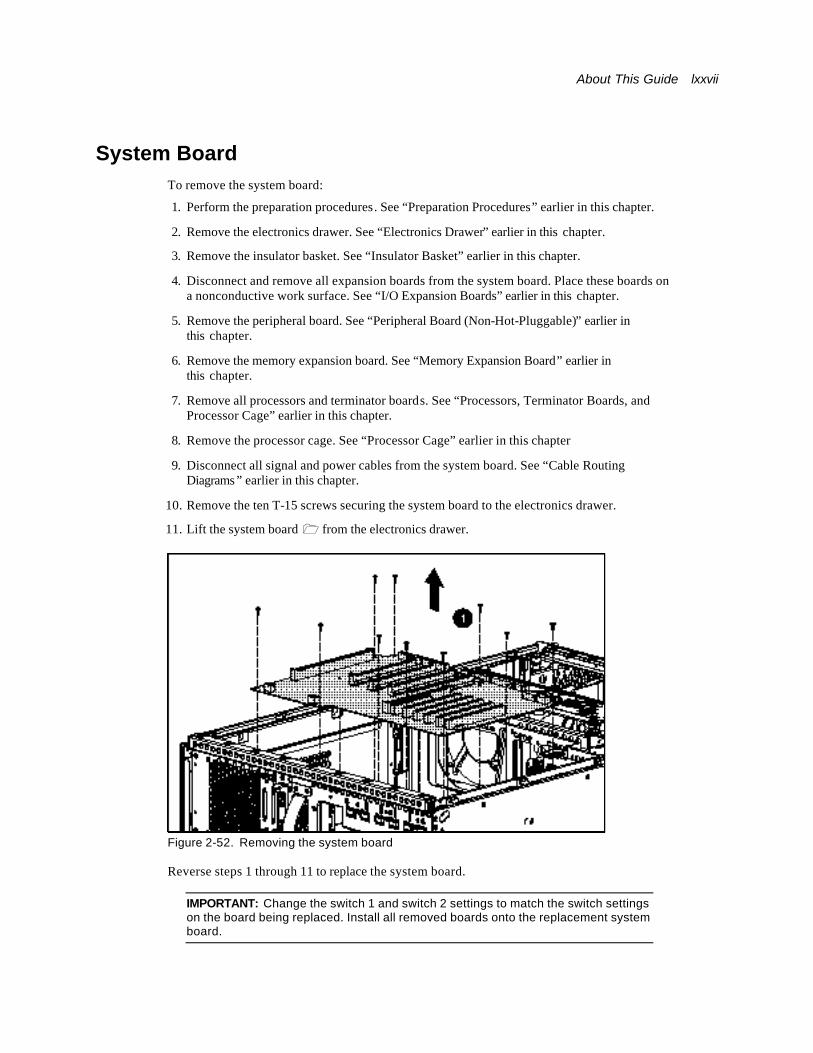
About This Guide lxxvii
System Board To remove the system board:
1. Perform the preparation procedures. See “Preparation Procedures” earlier in this chapter.
2. Remove the electronics drawer. See “Electronics Drawer” earlier in this chapter.
3. Remove the insulator basket. See “Insulator Basket” earlier in this chapter.
4. Disconnect and remove all expansion boards from the system board. Place these boards on a nonconductive work surface. See “I/O Expansion Boards” earlier in this chapter.
5. Remove the peripheral board. See “Peripheral Board (Non-Hot-Pluggable)” earlier in this chapter.
6. Remove the memory expansion board. See “Memory Expansion Board” earlier in this chapter.
7. Remove all processors and terminator boards. See “Processors, Terminator Boards, and Processor Cage” earlier in this chapter.
8. Remove the processor cage. See “Processor Cage” earlier in this chapter
9. Disconnect all signal and power cables from the system board. See “Cable Routing Diagrams ” earlier in this chapter.
10. Remove the ten T-15 screws securing the system board to the electronics drawer.
11. Lift the system board 1 from the electronics drawer.
Figure 2-52. Removing the system board
Reverse steps 1 through 11 to replace the system board.
IMPORTANT: Change the switch 1 and switch 2 settings to match the switch settings on the board being replaced. Install all removed boards onto the replacement system board.

lxxviii Compaq ProLiant ML570 Maintenance and Service Guide
Replacement Battery To remove the CMOS battery and to install the replacement battery:
CAUTION: Do not dispose of batteries, battery packs, and accumulators with the general household waste. To forward them to recycling or proper disposal, use the public collection system or return them to either Compaq or your Compaq authorized service provider.
1. Perform the preparation procedures. See “Preparation Procedures” earlier in this chapter.
2. Remove the access panel. See “Access Panel (Tower and Rack)” earlier in this chapter.
3. Remove the peripheral board. See “Peripheral Board (Non-Hot-Pluggable)” earlier in this chapter.
WARNING: Disconnect all power cords to completely remove power from the system before removing the peripheral board.
4. Remove the lithium battery from the peripheral board as shown in Figure 2-53.
Figure 2-53. Removing the lithium battery from the peripheral board
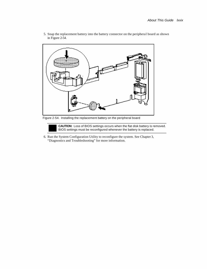
About This Guide lxxix
5. Snap the replacement battery into the battery connector on the peripheral board as shown in Figure 2-54.
Figure 2-54. Installing the replacement battery on the peripheral board
CAUTION: Loss of BIOS settings occurs when the flat disk battery is removed. BIOS settings must be reconfigured whenever the battery is replaced.
6. Run the System Configuration Utility to reconfigure the system. See Chapter 3, “Diagnostics and Troubleshooting” for more information.
Chapter 3
Diagnostics and Troubleshooting
This chapter describes software and firmware diagnostic tools available for all Compaq server products. The sections in this chapter are:
n Diagnostic Tools Utility Overview
n Default Configuration
n INSPECT
n Utilities Access
n Power-On Self-Test (POST)
n Diagnostics Software
n Array Diagnostic Utility (ADU)
n Integrated Management Log (IML)
n Rapid Error Recovery
n Remote Management Features
n ROMPaq™ Error Recovery Options
n Compaq Insight Manager™
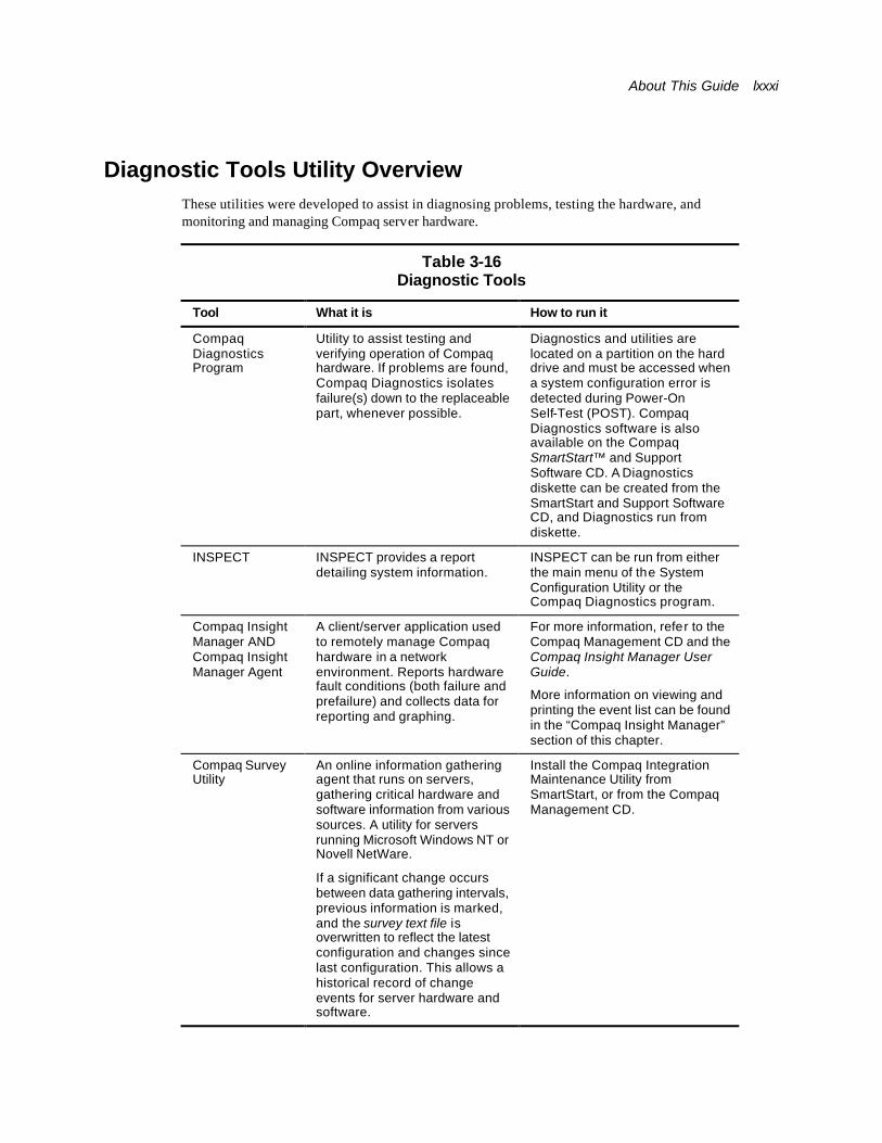
About This Guide lxxxi
Diagnostic Tools Utility Overview These utilities were developed to assist in diagnosing problems, testing the hardware, and monitoring and managing Compaq server hardware.
Table 3-16 Diagnostic Tools
Tool What it is How to run it
Compaq Diagnostics Program
Utility to assist testing and verifying operation of Compaq hardware. If problems are found, Compaq Diagnostics isolates failure(s) down to the replaceable part, whenever possible.
Diagnostics and utilities are located on a partition on the hard drive and must be accessed when a system configuration error is detected during Power-On Self-Test (POST). Compaq Diagnostics software is also available on the Compaq SmartStart™ and Support Software CD. A Diagnostics diskette can be created from the SmartStart and Support Software CD, and Diagnostics run from diskette.
INSPECT INSPECT provides a report detailing system information.
INSPECT can be run from either the main menu of the System Configuration Utility or the Compaq Diagnostics program.
Compaq Insight Manager AND Compaq Insight Manager Agent
A client/server application used to remotely manage Compaq hardware in a network environment. Reports hardware fault conditions (both failure and prefailure) and collects data for reporting and graphing.
For more information, refer to the Compaq Management CD and the Compaq Insight Manager User Guide.
More information on viewing and printing the event list can be found in the “Compaq Insight Manager” section of this chapter.
Compaq Survey Utility
An online information gathering agent that runs on servers, gathering critical hardware and software information from various sources. A utility for servers running Microsoft Windows NT or Novell NetWare.
If a significant change occurs between data gathering intervals, previous information is marked, and the survey text file is overwritten to reflect the latest configuration and changes since last configuration. This allows a historical record of change events for server hardware and software.
Install the Compaq Integration Maintenance Utility from SmartStart, or from the Compaq Management CD.

lxxxii Compaq ProLiant ML570 Maintenance and Service Guide
continued
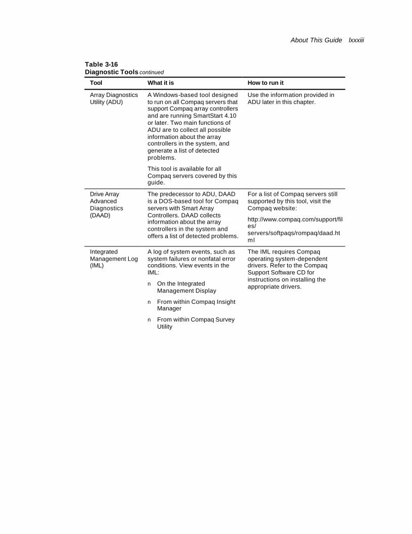
About This Guide lxxxiii
Table 3-16 Diagnostic Tools continued
Tool What it is How to run it
Array Diagnostics Utility (ADU)
A Windows-based tool designed to run on all Compaq servers that support Compaq array controllers and are running SmartStart 4.10 or later. Two main functions of ADU are to collect all possible information about the array controllers in the system, and generate a list of detected problems.
This tool is available for all Compaq servers covered by this guide.
Use the information provided in ADU later in this chapter.
Drive Array Advanced Diagnostics (DAAD)
The predecessor to ADU, DAAD is a DOS-based tool for Compaq servers with Smart Array Controllers. DAAD collects information about the array controllers in the system and offers a list of detected problems.
For a list of Compaq servers still supported by this tool, visit the Compaq website:
http://www.compaq.com/support/files/ servers/softpaqs/rompaq/daad.html
Integrated Management Log (IML)
A log of system events, such as system failures or nonfatal error conditions. View events in the IML:
n On the Integrated Management Display
n From within Compaq Insight Manager
n From within Compaq Survey Utility
The IML requires Compaq operating system-dependent drivers. Refer to the Compaq Support Software CD for instructions on installing the appropriate drivers.
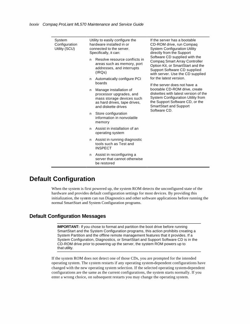
lxxxiv Compaq ProLiant ML570 Maintenance and Service Guide
System Configuration Utility (SCU)
Utility to easily configure the hardware installed in or connected to the server. Specifically, it can:
n Resolve resource confl icts in areas such as memory, port addresses, and interrupts (IRQs)
n Automatically configure PCI boards
n Manage installation of processor upgrades, and mass storage devices such as hard drives, tape drives, and diskette drives
n Store configuration information in nonvolatile memory
n Assist in installation of an operating system
n Assist in running diagnostic tools such as Test and INSPECT
n Assist in reconfiguring a server that cannot otherwise be restored
If the server has a bootable CD-ROM drive, run Compaq System Configuration Utility directly from the Support Software CD supplied with the Compaq Smart Array Controller Option Kit, or SmartStart and the Support Software CD supplied with server. Use the CD supplied for the latest version.
If the server does not have a bootable CD-ROM drive, create diskettes with latest version of the System Configuration Utility from the Support Software CD, or the SmartStart and Support Software CD.
Default Configuration When the system is first powered up, the system ROM detects the unconfigured state of the hardware and provides default configuration settings for most devices. By providing this initialization, the system can run Diagnostics and other software applications before running the normal SmartStart and System Configuration programs.
Default Configuration Messages
IMPORTANT: If you chose to format and partition the boot drive before running SmartStart and the System Configuration programs, this action prohibits creating a System Partition and the offline remote management features that it provides. If a System Configuration, Diagnostics, or SmartStart and Support Software CD is in the CD-ROM drive prior to powering up the server, the system ROM powers up to that utility.
If the system ROM does not detect one of those CDs, you are prompted for the intended operating system. The system restarts if any operating system-dependent configurations have changed with the new operating system selection. If the selected operating system-dependent configurations are the same as the current configurations, the system starts normally. If you enter a wrong choice, on subsequent restarts you may change the operating system.
About This Guide lxxxv
INSPECT
INSPECT provides configuration information such as the contents of the operating system (OS) startup files, current memory configuration, ROM version, and Integrated Management Log (IML) information. It operates with MS-DOS and in the MS-DOS emulation mode of MS OS/2.
Running INSPECT
6. Power down the server, then power up, and then press F10 when the cursor displays in the upper right corner of the screen.
7. At the main menu, select Diagnostics and Utilities.
8. Press Enter.
9. Select Inspect Computer, and then press Enter.
NOTE: If Diagnostics is not installed on the hard drive, System Configuration prompts you to insert the Diagnostics diskette into drive A.
10. Follow the instructions. The first time the INSPECT displays, select Entire System, and then press Enter.
Printing the INSPECT Listing
Select Print on the INSPECT screen to print a copy of the INSPECT listing. Keep a copy of the listing with each server for later reference.
Utilities Access The SmartStart and Support Software CD contains the SmartStart program and many of the Compaq utilities needed to maintain the system, including:
n System Configuration Utility
n Array Configuration Utility
n Array Diagnostic Utility (ADU)
n ROMPaq™ Firmware Upgrade Utilities
n Compaq Diagnostics
CAUTION: Do not select the Erase utility when running the SmartStart and Support Software CD. The erase utility causes data loss to the entire system.
Running the Utilities from the System Partition
If the system is installed with SmartStart, the Compaq utilities are automatically available on the system partition. The system partition could also have been created during a manual system installation.
To run the utilities on the system partition, start the system, and then press F10 when you see:
Press F10 for system partition utilities.
lxxxvi Compaq ProLiant ML570 Maintenance and Service Guide
Then select the desired utility from one of the following menus:
n System Configuration menu
q System Configuration Utility
q Array Configuration Utility
n Diagnostics and Utilities menu
q Compaq Diagnostics (Test and INSPECT)
q The ROMPaq Firmware Upgrade Utility
About This Guide lxxxvii
Running the Utilities from Diskette n Run the utilities from their individual diskettes. If you have a utility diskette newer than
the version on the SmartStart and Support Software CD, use that diskette.
n Create a diskette version of the utility from the SmartStart and Support Software CD.
To create diskette versions of the utilities from the CD:
1. Start the Compaq SmartStart and Support Software CD.
2. From the Compaq System Utilities screen, select Create Support Software Disks, and then select Next.
3. Select the diskette you would like to create from the list, and then follow the instructions on the screen.
Running the Utilities from the Compaq SmartStart and Support Software CD
IMPORTANT: Only the System Configuration Utility, the Array Configuration Utility, and the Array Diagnostic Utility (ADU) can be executed from the SmartStart and Support Software CD. All other utilities must be executed from either the system partition or from diskette.
To run these utilities directly from the SmartStart and Support Software CD:
4. Start the SmartStart and Support Software CD.
5. From the System Utilities screen, select the utility you wish to run, and then select Next.
q To execute the System Configuration Utility, select Run System Configuration Utility.
q To execute the Array Configuration Utility, select Run Array Configuration Utility.
q To execute the Array Diagnostic Utility (ADU), select Run Array Diagnostic Utility.

lxxxviii Compaq ProLiant ML570 Maintenance and Service Guide
Power-On Self-Test (POST) POST is a series of diagnostic tests that automatically run on Compaq computers when the system is powered up. POST checks the following assemblies to ensure that the computer system is functioning properly:
n System ROM
n Keyboard
n Power supply
n System board
n Memory
n Memory expansion boards
n Controllers
n Diskette drives
n Hard drives
n Fans
POST Error Messages
If POST finds an error in the system, an error condition is indicated by an audible and visual message. If an error code displays on the screen during POST or after resetting the system, use the instructions in the POST Error Messages table (Table 3-17).
NOTE: Many of the actions listed require you to run Diagnostics or the System Configuration Utility. Steps for running these utilities are provided following the POST Error Messages tables.
The Recommended Action column in Table 3-17 lists the steps necessary to correct the problem. After completing each step, run the Diagnostics program to verify whether the error condition has been corrected. If the error code is redisplayed, perform the next step, and then run the Diagnostics program again. Follow this procedure until Diagnostics no longer detects an error condition.

About This Guide lxxxix
Table 3-17 POST Error Messages
Error Code Audible Beeps Probable Source of Problem Recommended Action
A Critical Error occurred prior to this power-up
None A catastrophic system error, which caused the server to crash, has been logged.
Run Diagnostics. Replace failed assembly as indicated.
Unsupported Processor Detected System Halted
1 long, 1 short Processor not supported by current system ROM
Check documentation for supported processors, and if supported, remove the processor and update the system to latest ROM.
FATAL ROM ERROR: The System ROM is not properly programmed
1 long, 1 short ROM incorrectly programmed in factory
Replace the physical ROM part.
101-ROM Error 1 long, 1 short System ROM checksum Run Diagnostics, then replace failed assembly as indicated.
101-I/O ROM Error
None Options ROM checksum Run Diagnostics, then replace failed assembly as indicated.
102-System Board Failure
None DMA, timers Replace the system board. Run the System Configuration Utility.
104-ASR-2 Timer Failure
None System board failure Run Diagnostics. Replace failed assembly as indicated.
105-Current System ROM is corrupt – now booting redundant System ROM
2 long Nonbooted ROM image is corrupt
Flash the ROM utilizing ROMPaq.
162-System Options Not Set
2 short Configuration incorrect Run the System Configuration Utility and correct.
163-Time & Date Not Set
2 short Invalid time or date in configuration memory
Run the System Configuration Utility and correct.
164-Memory Size Error
2 short Configuration memory incorrect
Run the System Configuration Utility and correct.
172-Configuration Nonvolatile Memory Invalid
None Nonvolatile configuration corrupt or jumper installed
Run the System Configuration Utility and correct.
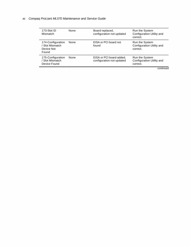
xc Compaq ProLiant ML570 Maintenance and Service Guide
173-Slot ID Mismatch
None Board replaced, configuration not updated
Run the System Configuration Utility and correct.
174-Configuration/ Slot Mismatch Device Not Found
None EISA or PCI board not found
Run the System Configuration Utility and correct.
175-Configuration/ Slot Mismatch Device Found
None EISA or PCI board added, configuration not updated
Run the System Configuration Utility and correct.
continued
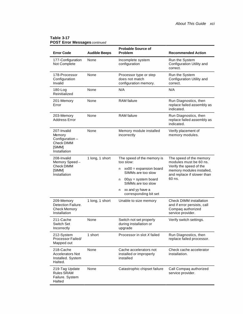
About This Guide xci
Table 3-17 POST Error Messages continued
Error Code Audible Beeps Probable Source of Problem Recommended Action
177-Configuration Not Complete
None Incomplete system configuration
Run the System Configuration Utility and correct.
178-Processor Configuration Invalid
None Processor type or step does not match configuration memory.
Run the System Configuration Utility and correct.
180-Log Reinitialized
None N/A N/A
201-Memory Error
None RAM failure Run Diagnostics, then replace failed assembly as indicated.
203-Memory Address Error
None RAM failure Run Diagnostics, then replace failed assembly as indicated.
207-Invalid Memory Configuration – Check DIMM [SIMM] Installation
None Memory module installed incorrectly
Verify placement of memory modules.
208-Invalid Memory Speed – Check DIMM [SIMM] Installation
1 long, 1 short The speed of the memory is too slow:
n xx00 = expansion board SIMMs are too slow
n 00yy = system board SIMMs are too slow
n xx and yy have a corresponding bit set
The speed of the memory modules must be 60 ns. Verify the speed of the memory modules installed, and replace if slower than 60 ns.
209-Memory Detection Failure. Check Memory Installation
1 long, 1 short Unable to size memory Check DIMM installation and if error persists, call Compaq authorized service provider.
211-Cache Switch Set Incorrectly
None Switch not set properly during installation or upgrade
Verify switch settings.
212-System Processor Failed/ Mapped out
1 short Processor in slot X failed Run Diagnostics, then replace failed processor.
218-Cache Accelerators Not Installed. System Halted.
None Cache accelerators not installed or improperly installed
Check cache accelerator installation.
219-Tag Update Rules SRAM Failure. System Halted
None Catastrophic chipset failure Call Compaq authorized service provider.

xcii Compaq ProLiant ML570 Maintenance and Service Guide
continued
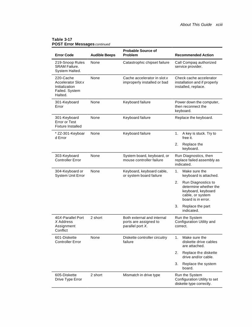
About This Guide xciii
Table 3-17 POST Error Messages continued
Error Code Audible Beeps Probable Source of Problem Recommended Action
219-Snoop Rules SRAM Failure. System Halted.
None Catastrophic chipset failure Call Compaq authorized service provider.
220-Cache Accelerator Slot x Initialization Failed. System Halted.
None Cache accelerator in slot x improperly installed or bad
Check cache accelerator installation and if properly installed, replace.
301-Keyboard Error
None Keyboard failure Power down the computer, then reconnect the keyboard.
301-Keyboard Error or Test Fixture Installed
None Keyboard failure Replace the keyboard.
* ZZ-301-Keyboard Error
None Keyboard failure 1. A key is stuck. Try to free it.
2. Replace the keyboard.
303-Keyboard Controller Error
None System board, keyboard, or mouse controller failure
Run Diagnostics, then replace failed assembly as indicated.
304-Keyboard or System Unit Error
None Keyboard, keyboard cable, or system board failure
1. Make sure the keyboard is attached.
2. Run Diagnostics to determine whether the keyboard, keyboard cable, or system board is in error.
3. Replace the part indicated.
40X-Parallel Port X Address Assignment Conflict
2 short Both external and internal ports are assigned to parallel port X.
Run the System Configuration Utility and correct.
601-Diskette Controller Error
None Diskette controller circuitry failure
1. Make sure the diskette drive cables are attached.
2. Replace the diskette drive and/or cable.
3. Replace the system board.
605-Diskette Drive Type Error
2 short Mismatch in drive type Run the System Configuration Utility to set diskette type correctly.

xciv Compaq ProLiant ML570 Maintenance and Service Guide
1151-Com Port 1 Address Assignment Conflict
2 short Both external and internal serial ports are assigned to COM1.
Run the System Configuration Utility and correct.
* ZZ represents the Keyboard Scan Code.
continued
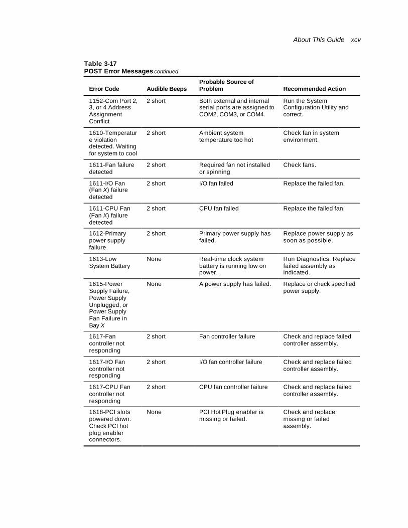
About This Guide xcv
Table 3-17 POST Error Messages continued
Error Code Audible Beeps Probable Source of Problem Recommended Action
1152-Com Port 2, 3, or 4 Address Assignment Conflict
2 short Both external and internal serial ports are assigned to COM2, COM3, or COM4.
Run the System Configuration Utility and correct.
1610-Temperature violation detected. Waiting for system to cool
2 short Ambient system temperature too hot
Check fan in system environment.
1611-Fan failure detected
2 short Required fan not installed or spinning
Check fans.
1611-I/O Fan (Fan X) failure detected
2 short I/O fan failed Replace the failed fan.
1611-CPU Fan (Fan X) failure detected
2 short CPU fan failed Replace the failed fan.
1612-Primary power supply failure
2 short Primary power supply has failed.
Replace power supply as soon as possible.
1613-Low System Battery
None Real-time clock system battery is running low on power.
Run Diagnostics. Replace failed assembly as indicated.
1615-Power Supply Failure, Power Supply Unplugged, or Power Supply Fan Failure in Bay X
None A power supply has failed. Replace or check specified power supply.
1617-Fan controller not responding
2 short Fan controller failure Check and replace failed controller assembly.
1617-I/O Fan controller not responding
2 short I/O fan controller failure Check and replace failed controller assembly.
1617-CPU Fan controller not responding
2 short CPU fan controller failure Check and replace failed controller assembly.
1618-PCI slots powered down. Check PCI hot plug enabler connectors.
None PCI Hot Plug enabler is missing or failed.
Check and replace missing or failed assembly.
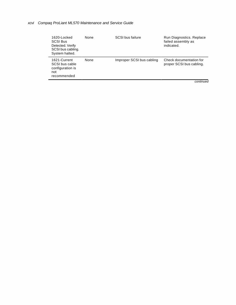
xcvi Compaq ProLiant ML570 Maintenance and Service Guide
1620-Locked SCSI Bus Detected. Verify SCSI bus cabling. System halted.
None SCSI bus failure Run Diagnostics. Replace failed assembly as indicated.
1621-Current SCSI bus cable configuration is not recommended
None Improper SCSI bus cabling Check documentation for proper SCSI bus cabling.
continued
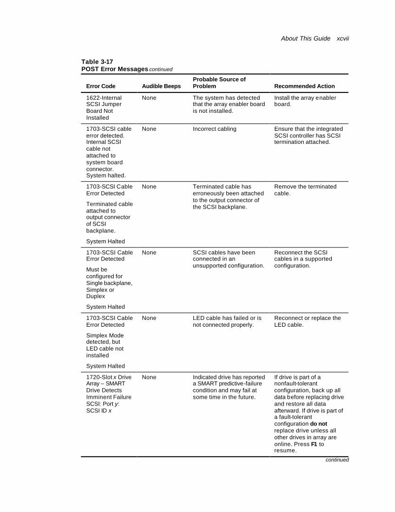
About This Guide xcvii
Table 3-17 POST Error Messages continued
Error Code Audible Beeps Probable Source of Problem Recommended Action
1622-Internal SCSI Jumper Board Not Installed
None The system has detected that the array enabler board is not installed.
Install the array enabler board.
1703-SCSI cable error detected. Internal SCSI cable not attached to system board connector. System halted.
None Incorrect cabling Ensure that the integrated SCSI controller has SCSI termination attached.
1703-SCSI Cable Error Detected
Terminated cable attached to output connector of SCSI backplane.
System Halted
None Terminated cable has erroneously been attached to the output connector of the SCSI backplane.
Remove the terminated cable.
1703-SCSI Cable Error Detected
Must be configured for Single backplane, Simplex or Duplex
System Halted
None SCSI cables have been connected in an unsupported configuration.
Reconnect the SCSI cables in a supported configuration.
1703-SCSI Cable Error Detected
Simplex Mode detected, but LED cable not installed
System Halted
None LED cable has failed or is not connected properly.
Reconnect or replace the LED cable.
1720-Slot x Drive Array – SMART Drive Detects Imminent Failure SCSI: Port y: SCSI ID x
None Indicated drive has reported a SMART predictive-failure condition and may fail at some time in the future.
If drive is part of a nonfault-tolerant configuration, back up all data before replacing drive and restore all data afterward. If drive is part of a fault-tolerant configuration do not replace drive unless all other drives in array are online. Press F1 to resume.
continued
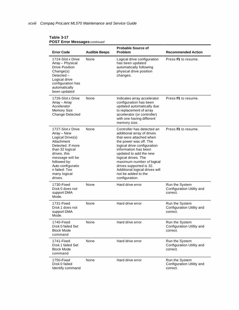
xcviii Compaq ProLiant ML570 Maintenance and Service Guide
Table 3-17 POST Error Messages continued
Error Code Audible Beeps Probable Source of Problem Recommended Action
1724-Slot x Drive Array – Physical Drive Position Change(s) Detected – Logical drive configuration has automatically been updated
None Logical drive configuration has been updated automatically following physical drive position changes.
Press F1 to resume.
1726-Slot x Drive Array – Array Accelerator Memory Size Change Detected
None Indicates array accelerator configuration has been updated automatically due to replacement of array accelerator (or controller) with one having different memory size.
Press F1 to resume.
1727-Slot x Drive Array – New Logical Drive(s) Attachment Detected. If more than 32 logical drives, this message will be followed by: Auto-configuration failed: Too many logical drives.
None Controller has detected an additional array of drives that were attached when the power was off. The logical drive configuration information has been updated to add the new logical drives. The maximum number of logical drives supported is 32. Additional logical drives will not be added to the configuration.
Press F1 to resume.
1730-Fixed Disk 0 does not support DMA Mode.
None Hard drive error Run the System Configuration Utility and correct.
1731-Fixed Disk 1 does not support DMA Mode.
None Hard drive error Run the System Configuration Utility and correct.
1740-Fixed Disk 0 failed Set Block Mode command
None Hard drive error Run the System Configuration Utility and correct.
1741-Fixed Disk 1 failed Set Block Mode command
None Hard drive error Run the System Configuration Utility and correct.
1750-Fixed Disk 0 failed Identify command
None Hard drive error Run the System Configuration Utility and correct.
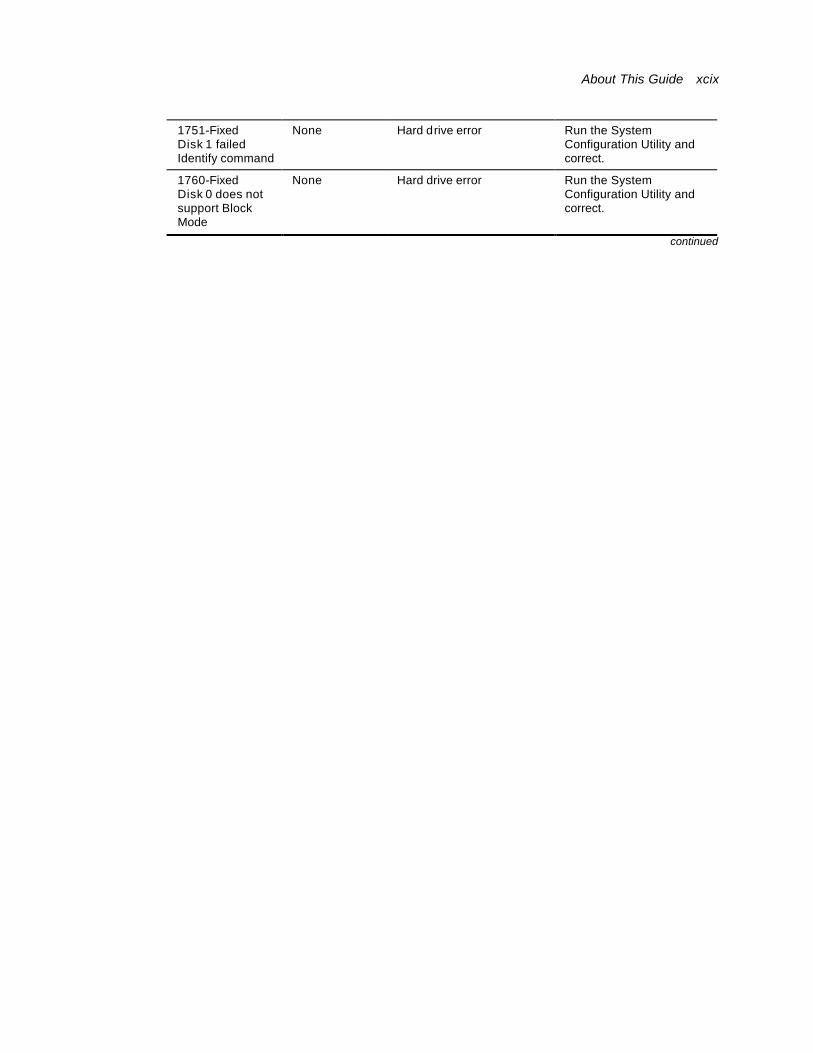
About This Guide xcix
1751-Fixed Disk 1 failed Identify command
None Hard drive error Run the System Configuration Utility and correct.
1760-Fixed Disk 0 does not support Block Mode
None Hard drive error Run the System Configuration Utility and correct.
continued
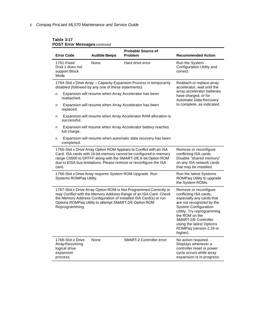
c Compaq ProLiant ML570 Maintenance and Service Guide
Table 3-17 POST Error Messages continued
Error Code Audible Beeps Probable Source of Problem Recommended Action
1761-Fixed Disk 1 does not support Block Mode
None Hard drive error Run the System Configuration Utility and correct.
1764-Slot x Drive Array – Capacity Expansion Process is temporarily disabled (followed by any one of these statements):
n Expansion will resume when Array Accelerator has been reattached.
n Expansion will resume when Array Accelerator has been replaced.
n Expansion will resume when Array Accelerator RAM allocation is successful.
n Expansion will resume when Array Accelerator battery reaches full charge.
n Expansion will resume when automatic data recovery has been completed.
Reattach or replace array accelerator, wait until the array accelerator batteries have charged, or for Automatic Data Recovery to complete, as indicated.
1765-Slot x Drive Array Option ROM Appears to Conflict with an ISA Card. ISA cards with 16-bit memory cannot be configured in memory range C0000 to DFFFF along with the SMART-2/E 8-bit Option ROM due to EISA bus limitations. Please remove or reconfigure the ISA card.
Remove or reconfigure conflicting ISA cards. Disable “shared memory” on any ISA network cards that may be installed.
1766-Slot x Drive Array requires System ROM Upgrade. Run Systems ROMPaq Utility.
Run the latest Systems ROMPaq Utility to upgrade the System ROMs.
1767-Slot x Drive Array Option ROM is Not Programmed Correctly or may Conflict with the Memory Address Range of an ISA Card. Check the Memory Address Configuration of installed ISA Card(s) or run Options ROMPaq Utility to attempt SMART-2/E Option ROM Reprogramming.
Remove or reconfigure conflicting ISA cards, especially any cards that are not recognized by the System Configuration Utility. Try reprogramming the ROM on the SMART-2/E Controller using the latest Options ROMPaq (version 2.29 or higher).
1768-Slot x Drive Array-Resuming logical drive expansion process.
None SMART-2 Controller error No action required. Displays whenever a controller reset or power cycle occurs while array expansion is in progress.

About This Guide ci
1769-Slot x Drive Array – Drive(s) disabled due to failure during expand. Select F1 to continue with logical drives disabled. Select F2 to accept data loss and to re-enable logical drives.
None SMART-2 Controller error. Data has been lost while expanding the array; therefore, the drives have been temporarily disabled.
Press F2 to accept the data loss and re-enable the logical drives. Restore data from backup.
continued

cii Compaq ProLiant ML570 Maintenance and Service Guide
Table 3-17 POST Error Messages continued
Error Code Audible Beeps Probable Source of Problem Recommended Action
1771-Primary Disk Port Address Assignment Conflict
None Internal and external hard drive controllers are both assigned to the primary address.
Run the System Configuration Utility and correct.
1772-Secondary Disk Port Address Assignment Conflict
None Address Assignment Conflict. Internal and external hard drive controllers are both assigned to the secondary address.
Run the System Configuration Utility and correct.
1773-Primary Fixed Disk Port Assignment Conflict
None Fixed disk drive error Run the System Configuration Utility and correct.
1774-Slot x Drive Array – Obsolete data found in Array Accelerator. Select F1 to discard contents of Array Accelerator. Select F2 to write contents of Array Accelerator to drives.
None SMART-2 Controller error Data found in array accelerator is older than data found on drives. Press F1 to discard the older data in the array accelerator and retain the newer data on the drives.
1775-Slot x Drive Array – ProLiant Storage System Not Responding SCSI Port (y): Check storage system power switch and cables. Turn the system power off while checking the ProLiant power and cable connections, then turn the system power back on to retry.
None Storage system problem Power down the system. Check external ProLiant power switch – external drives must all be powered up before or at the same time as the main system. Check cables. If retry does not help, try replacing the cable, ProLiant firmware, ProLiant backplane, or the Smart Array Controller.
1776-Drive Array SCSI Port Termination Error
None External and internal SCSI drives are both configured to Port 1.
Reconfigure drives.
1777-Drive Array External Drive Subsystem Error
None Cooling fan failure, internal temperature alert, or open side panel
Inspect for cooling fan failure or open side panel.

About This Guide ciii
continued
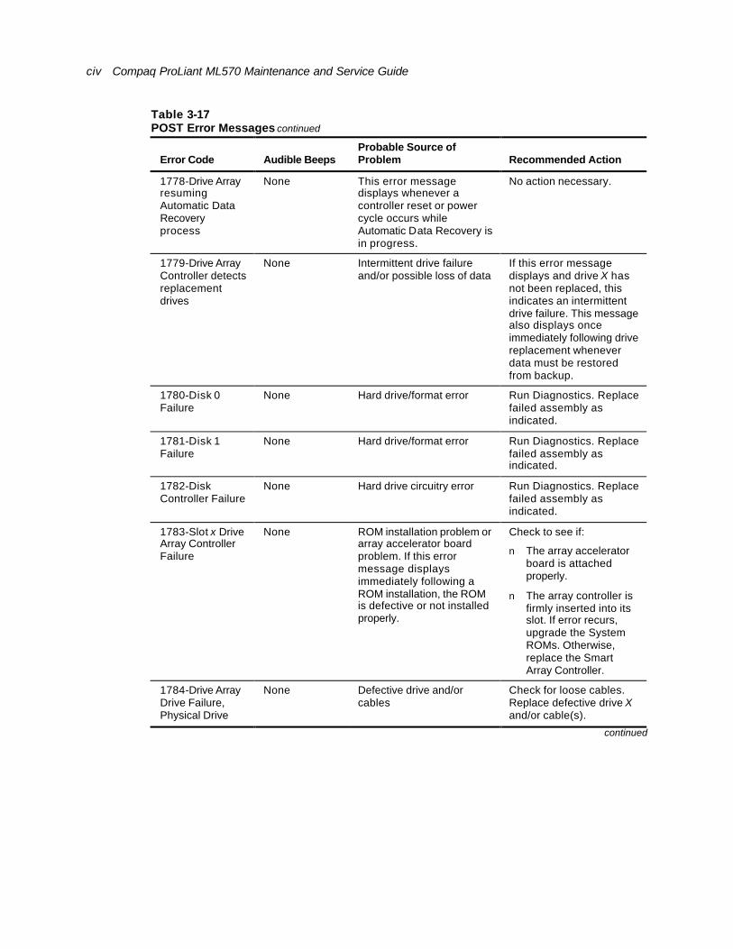
civ Compaq ProLiant ML570 Maintenance and Service Guide
Table 3-17 POST Error Messages continued
Error Code Audible Beeps Probable Source of Problem Recommended Action
1778-Drive Array resuming Automatic Data Recovery process
None This error message displays whenever a controller reset or power cycle occurs while Automatic Data Recovery is in progress.
No action necessary.
1779-Drive Array Controller detects replacement drives
None Intermittent drive failure and/or possible loss of data
If this error message displays and drive X has not been replaced, this indicates an intermittent drive failure. This message also displays once immediately following drive replacement whenever data must be restored from backup.
1780-Disk 0 Failure
None Hard drive/format error Run Diagnostics. Replace failed assembly as indicated.
1781-Disk 1 Failure
None Hard drive/format error Run Diagnostics. Replace failed assembly as indicated.
1782-Disk Controller Failure
None Hard drive circuitry error Run Diagnostics. Replace failed assembly as indicated.
1783-Slot x Drive Array Controller Failure
None ROM installation problem or array accelerator board problem. If this error message displays immediately following a ROM installation, the ROM is defective or not installed properly.
Check to see if:
n The array accelerator board is attached properly.
n The array controller is firmly inserted into its slot. If error recurs, upgrade the System ROMs. Otherwise, replace the Smart Array Controller.
1784-Drive Array Drive Failure, Physical Drive
None Defective drive and/or cables
Check for loose cables. Replace defective drive X and/or cable(s).
continued
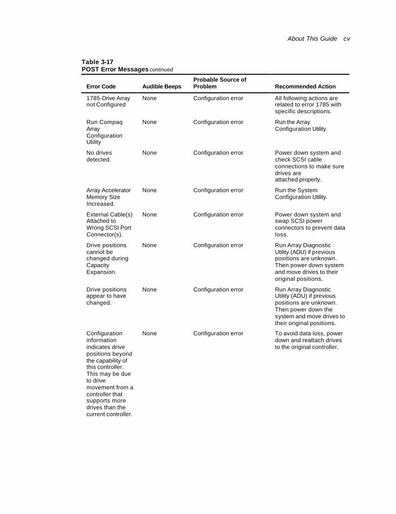
About This Guide cv
Table 3-17 POST Error Messages continued
Error Code Audible Beeps Probable Source of Problem Recommended Action
1785-Drive Array not Configured
None Configuration error All following actions are related to error 1785 with specific descriptions.
Run Compaq Array Configuration Utility
None Configuration error Run the Array Configuration Utility.
No drives detected.
None Configuration error Power down system and check SCSI cable connections to make sure drives are attached properly.
Array Accelerator Memory Size Increased.
None Configuration error Run the System Configuration Utility.
External Cable(s) Attached to Wrong SCSI Port Connector(s).
None Configuration error Power down system and swap SCSI power connectors to prevent data loss.
Drive positions cannot be changed during Capacity Expansion.
None Configuration error Run Array Diagnostic Utility (ADU) if previous positions are unknown. Then power down system and move drives to their original positions.
Drive positions appear to have changed.
None Configuration error Run Array Diagnostic Utility (ADU) if previous positions are unknown. Then power down the system and move drives to their original positions.
Configuration information indicates drive positions beyond the capability of this controller. This may be due to drive movement from a controller that supports more drives than the current controller.
None Configuration error To avoid data loss, power down and reattach drives to the original controller.
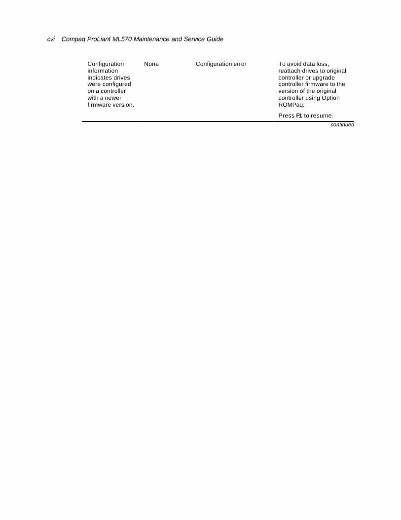
cvi Compaq ProLiant ML570 Maintenance and Service Guide
Configuration information indicates drives were configured on a controller with a newer firmware version.
None Configuration error To avoid data loss, reattach drives to original controller or upgrade controller firmware to the version of the original controller using Option ROMPaq.
Press F1 to resume. continued

About This Guide cvii
Table 3-17 POST Error Messages continued
Error Code Audible Beeps Probable Source of Problem Recommended Action
1786-Drive Array Recovery Needed
The following drive(s) need Automatic Data Recovery: Drive X.
Select “F1” to continue with recovery of data to drive(s).
Select “F2” to continue without recovery of data to drive(s).
None Interim Data Recovery mode. Data has not been recovered yet.
Press F1 to allow Automatic Data Recovery to begin. Data is automatically restored to drive X when the drive is replaced or when existing drive is working.
-Or-
Press F2 to allow the system to continue operating in the Interim Data Recovery mode.
1787-Drive Array Operating in Interim Recovery Mode.
Physical drive replacement needed: Drive X
None Hard drive X failed or cable is loose or defective. Following a system restart, this message reminds you that drive X is defective and fault tolerance is being used.
1. Replace drive X as soon as possible.
2. Check loose cables.
3. Replace defective cables.
*1788-Incorrect Drive Replaced: Drive X Drive(s) were incorrectly replaced: Drive Y Select “F1” to continue – drive array will remain disabled. Select “F2” to reset configuration – all data will be lost.
None The drives are disabled when they are not installed in their original positions. *
Reinstall the drives correctly as indicated.
Press F1 to restart the computer with the drive array disabled.
-Or-
Press F2 to use the drives as configured and lose all the data on them.
* The 1788 error message might display inadvertently due to a bad power cable connection to the drive or by noise on the data cable. If this message was due to a bad power cable connection, but not because of an incorrect drive replacement, repair the connection and press F2.
-Or-
If this message was not due to a bad power cable connection, and no drive replacement took place, this could indicate noise on the data cable. Check cable for proper routing.
continued

cviii Compaq ProLiant ML570 Maintenance and Service Guide
Table 3-17 POST Error Messages continued
Error Code Audible Beeps Probable Source of Problem Recommended Action
1789-Drive Not Responding, Physical Drive
Check cables or replace physical drive X.
Select “F1” to continue – drive array will remain disabled.
Select “F2” to fail drive(s) that are not responding.
Interim Recovery Mode will be enabled if configured for fault tolerance.
None Cable or hard drive failure 1. Check the cable connections.
2. Replace the cables.
3. Replace the drive. If you do not want to replace the drive now, press F2.
1790-Disk 0 Configuration Error
None Hard drive error or wrong drive type
Run the System Configuration Utility and Diagnostics and correct.
1791-Disk 1 Error None Hard drive error or wrong drive type
Run the System Configuration Utility and Diagnostics and correct.
1792-Drive Array Reports Valid Data Found in Array Accelerator.
Data will automatically be written to drive array.
None Indicates that while the system was in use, power was interrupted while data was in the array accelerator memory. Power was then restored within 8 to 10 days, and the data in the array accelerator was flushed to the drive array.
No data has been lost. Perform orderly system shutdowns to avoid data remaining in the array accelerator.
1793-Drive Array – Array Accelerator Battery Depleted – Data Lost
(Error message 1794 also displays.)
None Indicates that while the system was in use, power was interrupted while data was in the array accelerator memory. Array accelerator batteries failed. Power was not restored within 8 to 10 days. Data in array accelerator has been lost.
Perform orderly system shutdowns to avoid data remaining in the array accelerator.
continued
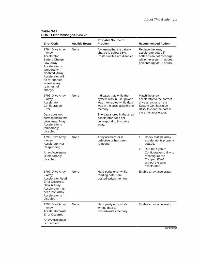
About This Guide cix
Table 3-17 POST Error Messages continued
Error Code Audible Beeps Probable Source of Problem Recommended Action
1794-Drive Array – Array Accelerator Battery Charge Low. Array Accelerator is temporarily disabled. Array Accelerator will be re-enabled when battery reaches full charge.
None A warning that the battery charge is below 75%. Posted-writes are disabled.
Replace the array accelerator board if batteries do not recharge while the system has been powered up for 36 hours.
1795-Drive Array – Array Accelerator Configuration Error.
Data does not correspond to this drive array. Array Accelerator is temporarily disabled.
None Indicates that while the system was in use, power was interrupted while data was in the array accelerator memory.
The data stored in the array accelerator does not correspond to this drive array.
Match the array accelerator to the correct drive array, or run the System Configuration Utility to clear the data in the array accelerator.
1796-Drive Array – Array Accelerator Not Responding.
Array Accelerator is temporarily disabled.
None Array accelerator is defective or has been removed.
1. Check that the array accelerator is properly seated.
2. Run the System Configuration Utility to reconfigure the Compaq IDA-2 without the array accelerator.
1797-Drive Array – Array Accelerator Read Error Occurred. Data in Array Accelerator has been lost. Array Accelerator is disabled.
None Hard parity error while reading data from posted-writes memory.
Enable array accelerator.
1798-Drive Array – Array Accelerator Write Error Occurred.
Array Accelerator is disabled.
None Hard parity error while writing data to posted-writes memory.
Enable array accelerator.
continued
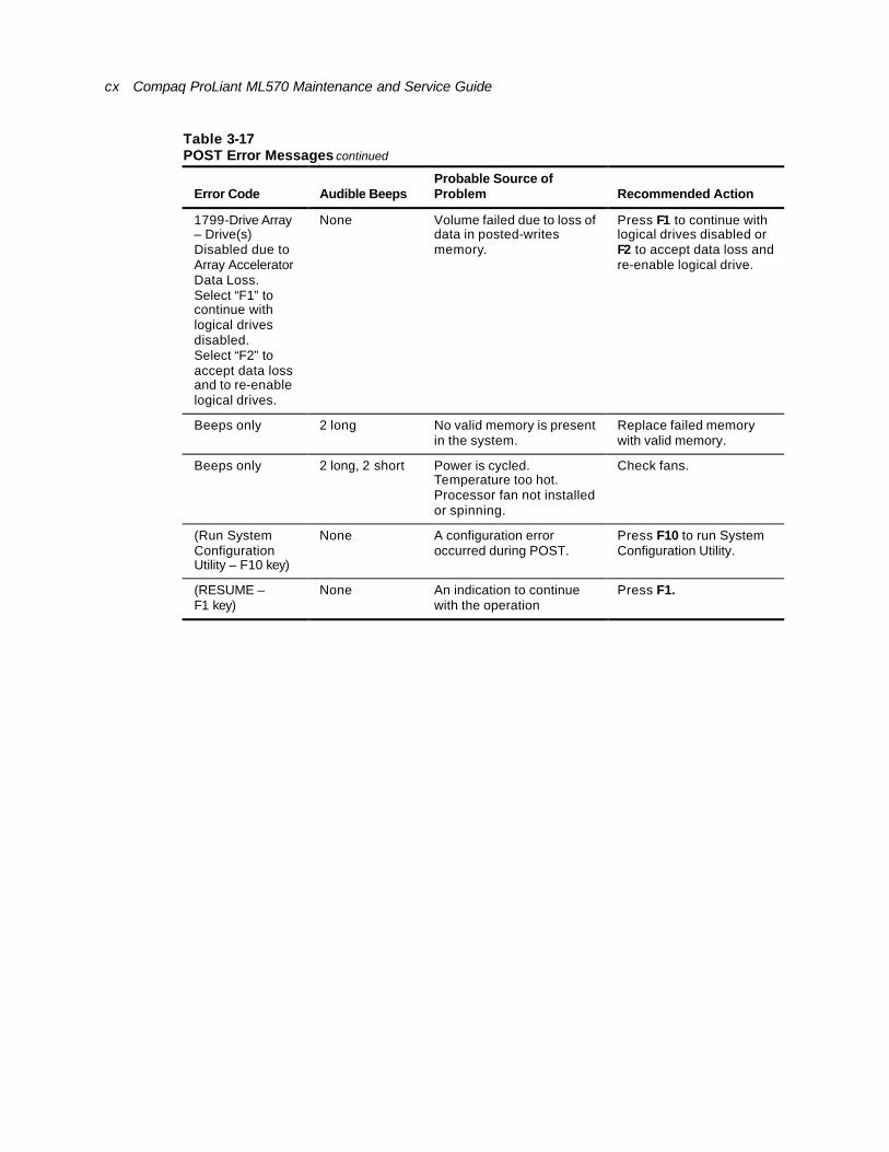
cx Compaq ProLiant ML570 Maintenance and Service Guide
Table 3-17 POST Error Messages continued
Error Code Audible Beeps Probable Source of Problem Recommended Action
1799-Drive Array – Drive(s) Disabled due to Array Accelerator Data Loss. Select “F1” to continue with logical drives disabled. Select “F2” to accept data loss and to re-enable logical drives.
None Volume failed due to loss of data in posted-writes memory.
Press F1 to continue with logical drives disabled or F2 to accept data loss and re-enable logical drive.
Beeps only 2 long No valid memory is present in the system.
Replace failed memory with valid memory.
Beeps only 2 long, 2 short Power is cycled. Temperature too hot. Processor fan not installed or spinning.
Check fans.
(Run System Configuration Utility – F10 key)
None A configuration error occurred during POST.
Press F10 to run System Configuration Utility.
(RESUME – F1 key)
None An indication to continue with the operation
Press F1.
About This Guide cxi
Diagnostics Software The Test Error Codes tables include all test error codes generated by Compaq products. Each code has a corresponding description and recommended action or actions. Each system generates only those codes that apply to its configuration and options.
When you select Diagnostics and Utilities from the System Configuration Utility main menu, the utility prompts you to test, inspect, upgrade, and diagnose the server.
Diagnostics and Utilities are located on the system partition on the hard drive and must be accessed when a system configuration error is detected during the Power-On Self-Test (POST). Diagnostics software is also available on the SmartStart and Support Software CD. You can create a Diagnostics diskette from the SmartStart and Support Software CD and run Diagnostics from diskette. See the “Running the Utilities from Diskette” procedure earlier in this chapter.
The following options are available from the Diagnostics and Utilities menu:
n Test Computer
n Inspect Computer
n Upgrade Firmware
n Remote Utilities
n Diagnose Drive Array
Diagnostic error codes are generated when the Diagnostics software recognizes a problem. These error codes help identify possible defective subassemblies.
Steps for Diagnostics
In each case, the Recommended Action column lists the steps necessary to correct the problem. After completing each step, run the Diagnostics utility to verify that the error condition has been corrected. If the error code is redisplayed:
6. Perform the next step listed in the table.
7. Run the Diagnostics utility program again.
8. Follow this procedure until the Diagnostics utility program no longer detects an error condition.

cxii Compaq ProLiant ML570 Maintenance and Service Guide
100 – 199, Primary Processor Test Error Codes
The 100 series of diagnostic error codes identifies failures with processor and system board functions. Corrective action may require replacing the system boards or processor assemblies.
Table 3-19 Primary Processor Test Error Codes
Error Code
Description Recommended Action
101-XX CPU test failed. Replace the processor board and retest.
103-XX DMA page registers test failed.
104-XX Interrupt controller master test failed.
105-XX Port 61 error.
106-XX Keyboard controller self-test failed.
Replace the processor board and retest.
107-XX CMOS RAM test failed.
108-XX CMOS interrupt test failed.
109-XX CMOS clock load data test failed.
1. Replace the battery/clock module and retest.
2. Replace the system board and retest.
110-XX Programmable timer load data test failed.
111-XX Refresh detect test failed.
112-XX Speed test slow mode out of range.
113-XX Protected mode test failed.
Replace the processor board and retest.
114-XX Speaker test failed. 1. Verify the speaker connection and retest.
2. Replace the speaker and retest.
3. Replace the system board and retest.
116-XX Cache test failed. Replace the system board and retest.
122-XX Multiprocessor dispatch test failed.
123-XX Interprocessor communication test failed.
1. Check the system configuration and retest.
2. Replace the processor board and retest.
3. Replace the system board and retest.
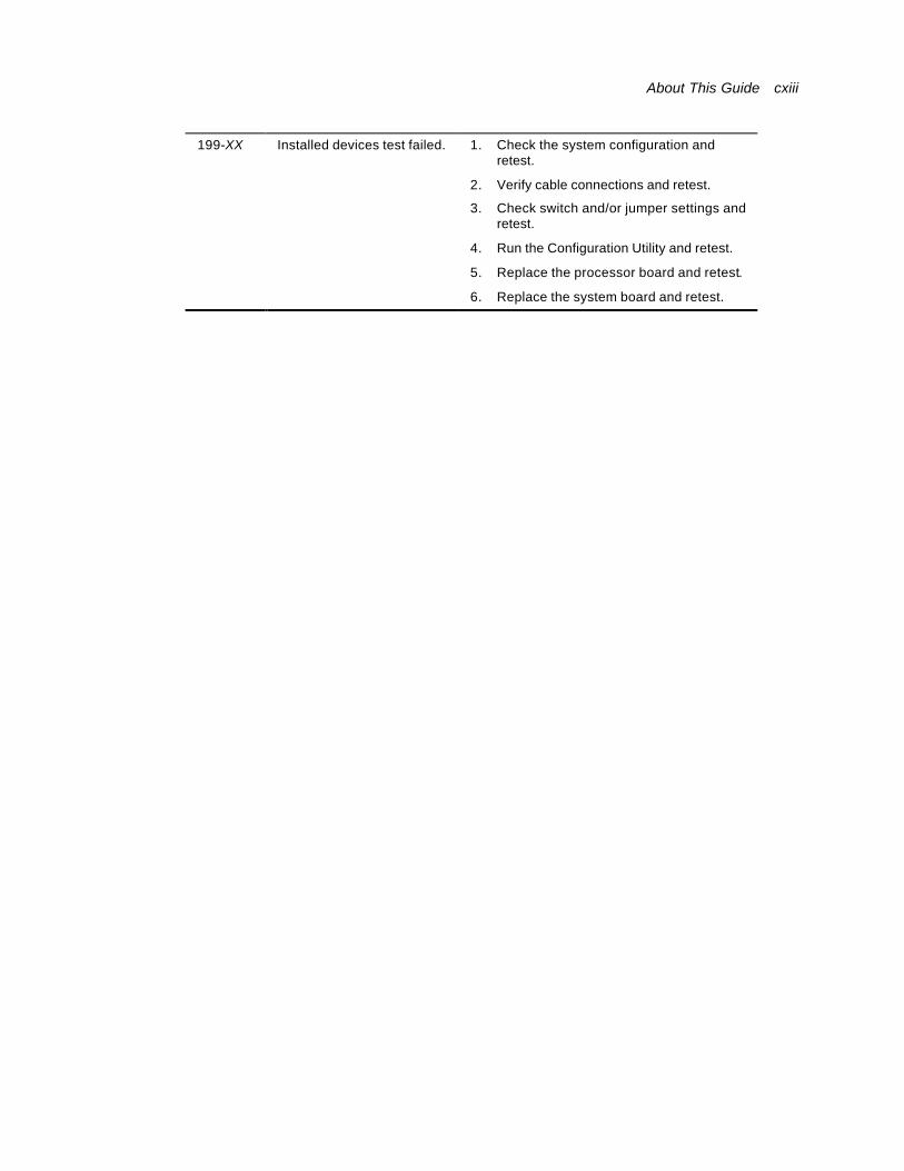
About This Guide cxiii
199-XX Installed devices test failed. 1. Check the system configuration and retest.
2. Verify cable connections and retest.
3. Check switch and/or jumper settings and retest.
4. Run the Configuration Utility and retest.
5. Replace the processor board and retest.
6. Replace the system board and retest.
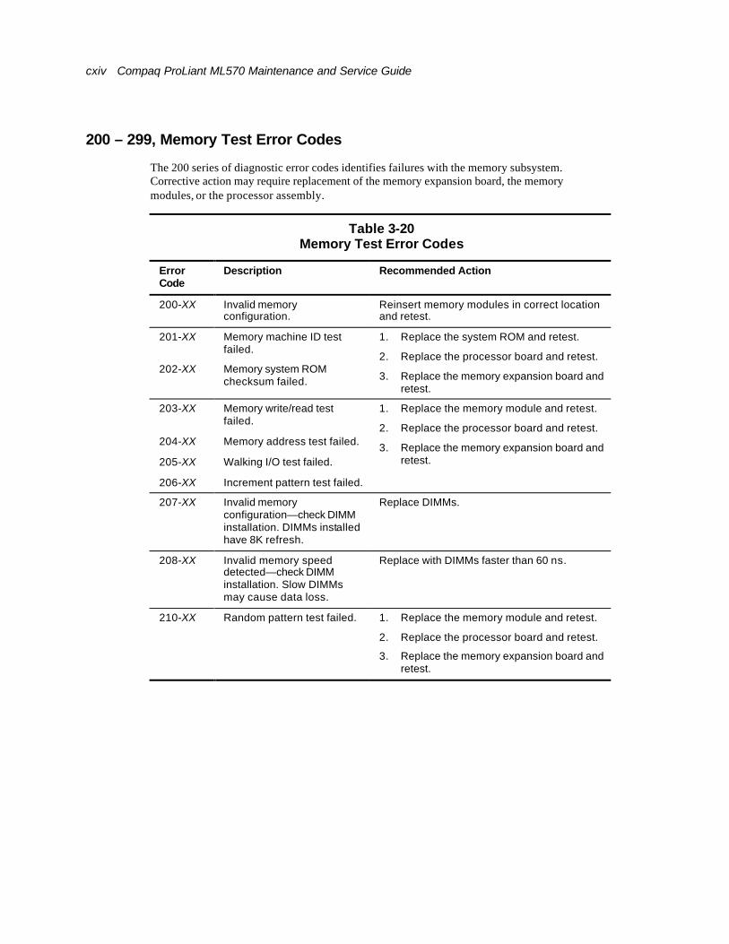
cxiv Compaq ProLiant ML570 Maintenance and Service Guide
200 – 299, Memory Test Error Codes
The 200 series of diagnostic error codes identifies failures with the memory subsystem. Corrective action may require replacement of the memory expansion board, the memory modules, or the processor assembly.
Table 3-20 Memory Test Error Codes
Error Code
Description Recommended Action
200-XX Invalid memory configuration.
Reinsert memory modules in correct location and retest.
201-XX Memory machine ID test failed.
202-XX Memory system ROM checksum failed.
1. Replace the system ROM and retest.
2. Replace the processor board and retest.
3. Replace the memory expansion board and retest.
203-XX Memory write/read test failed.
204-XX Memory address test failed.
205-XX Walking I/O test failed.
206-XX Increment pattern test failed.
1. Replace the memory module and retest.
2. Replace the processor board and retest.
3. Replace the memory expansion board and retest.
207-XX Invalid memory configuration—check DIMM installation. DIMMs installed have 8K refresh.
Replace DIMMs.
208-XX Invalid memory speed detected—check DIMM installation. Slow DIMMs may cause data loss.
Replace with DIMMs faster than 60 ns.
210-XX Random pattern test failed. 1. Replace the memory module and retest.
2. Replace the processor board and retest.
3. Replace the memory expansion board and retest.
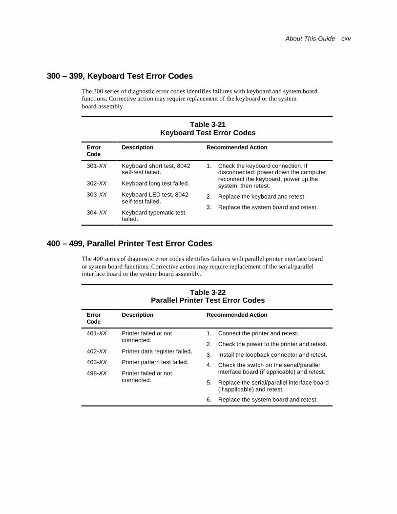
About This Guide cxv
300 – 399, Keyboard Test Error Codes
The 300 series of diagnostic error codes identifies failures with keyboard and system board functions. Corrective action may require replacement of the keyboard or the system board assembly.
Table 3-21 Keyboard Test Error Codes
Error Code
Description Recommended Action
301-XX Keyboard short test, 8042 self-test failed.
302-XX Keyboard long test failed.
303-XX Keyboard LED test, 8042 self-test failed.
304-XX Keyboard typematic test failed.
1. Check the keyboard connection. If disconnected: power down the computer, reconnect the keyboard, power up the system, then retest.
2. Replace the keyboard and retest.
3. Replace the system board and retest.
400 – 499, Parallel Printer Test Error Codes
The 400 series of diagnostic error codes identifies failures with parallel printer interface board or system board functions. Corrective action may require replacement of the serial/parallel interface board or the system board assembly.
Table 3-22 Parallel Printer Test Error Codes
Error Code
Description Recommended Action
401-XX Printer failed or not connected.
402-XX Printer data register failed.
403-XX Printer pattern test failed.
498-XX Printer failed or not connected.
1. Connect the printer and retest.
2. Check the power to the printer and retest.
3. Install the loopback connector and retest.
4. Check the switch on the serial/parallel interface board (if applicable) and retest.
5. Replace the serial/parallel interface board (if applicable) and retest.
6. Replace the system board and retest.
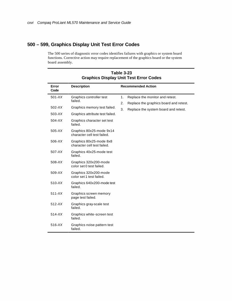
cxvi Compaq ProLiant ML570 Maintenance and Service Guide
500 – 599, Graphics Display Unit Test Error Codes
The 500 series of diagnostic error codes identifies failures with graphics or system board functions. Corrective action may require replacement of the graphics board or the system board assembly.
Table 3-23 Graphics Display Unit Test Error Codes
Error Code
Description Recommended Action
501-XX Graphics controller test failed.
502-XX Graphics memory test failed.
503-XX Graphics attribute test failed.
504-XX Graphics character set test failed.
505-XX Graphics 80x25-mode 9x14 character cell test failed.
506-XX Graphics 80x25-mode 8x8 character cell test failed.
507-XX Graphics 40x25-mode test failed.
508-XX Graphics 320x200-mode color set 0 test failed.
509-XX Graphics 320x200-mode color set 1 test failed.
510-XX Graphics 640x200-mode test failed.
511-XX Graphics screen memory page test failed.
512-XX Graphics gray-scale test failed.
514-XX Graphics white-screen test failed.
516-XX Graphics noise pattern test failed.
1. Replace the monitor and retest.
2. Replace the graphics board and retest.
3. Replace the system board and retest.
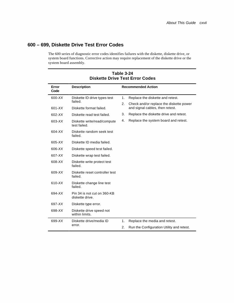
About This Guide cxvii
600 – 699, Diskette Drive Test Error Codes
The 600 series of diagnostic error codes identifies failures with the diskette, diskette drive, or system board functions. Corrective action may require replacement of the diskette drive or the system board assembly.
Table 3-24 Diskette Drive Test Error Codes
Error Code
Description Recommended Action
600-XX Diskette ID drive types test failed.
601-XX Diskette format failed.
602-XX Diskette read test failed.
603-XX Diskette write/read/compute test failed.
604-XX Diskette random seek test failed.
605-XX Diskette ID media failed.
606-XX Diskette speed test failed.
607-XX Diskette wrap test failed.
608-XX Diskette write protect test failed.
609-XX Diskette reset controller test failed.
610-XX Diskette change line test failed.
694-XX Pin 34 is not cut on 360-KB diskette drive.
697-XX Diskette type error.
698-XX Diskette drive speed not within limits.
1. Replace the diskette and retest.
2. Check and/or replace the diskette power and signal cables, then retest.
3. Replace the diskette drive and retest.
4. Replace the system board and retest.
699-XX Diskette drive/media ID error.
1. Replace the media and retest.
2. Run the Configuration Utility and retest.
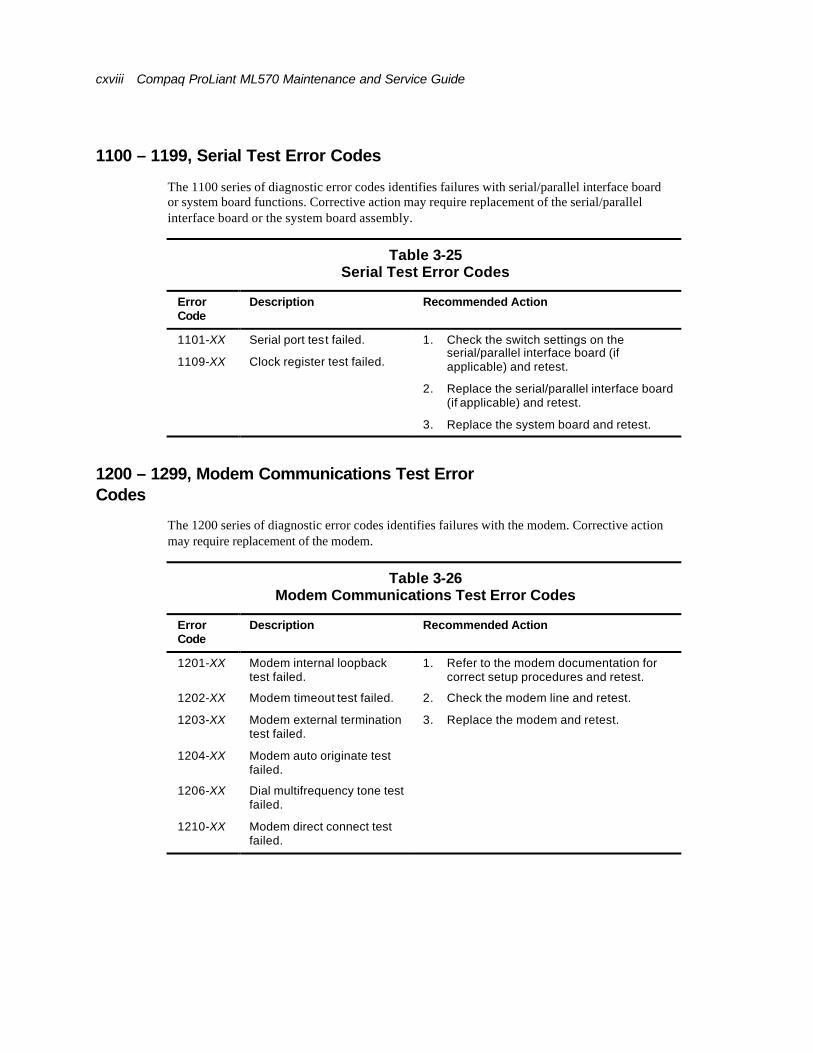
cxviii Compaq ProLiant ML570 Maintenance and Service Guide
1100 – 1199, Serial Test Error Codes
The 1100 series of diagnostic error codes identifies failures with serial/parallel interface board or system board functions. Corrective action may require replacement of the serial/parallel interface board or the system board assembly.
Table 3-25 Serial Test Error Codes
Error Code
Description Recommended Action
1101-XX Serial port test failed.
1109-XX Clock register test failed.
1. Check the switch settings on the serial/parallel interface board (if applicable) and retest.
2. Replace the serial/parallel interface board (if applicable) and retest.
3. Replace the system board and retest.
1200 – 1299, Modem Communications Test Error Codes
The 1200 series of diagnostic error codes identifies failures with the modem. Corrective action may require replacement of the modem.
Table 3-26 Modem Communications Test Error Codes
Error Code
Description Recommended Action
1201-XX Modem internal loopback test failed.
1202-XX Modem timeout test failed.
1203-XX Modem external termination test failed.
1204-XX Modem auto originate test failed.
1206-XX Dial multifrequency tone test failed.
1210-XX Modem direct connect test failed.
1. Refer to the modem documentation for correct setup procedures and retest.
2. Check the modem line and retest.
3. Replace the modem and retest.
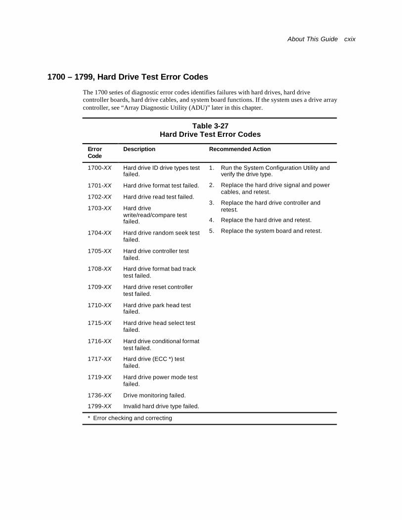
About This Guide cxix
1700 – 1799, Hard Drive Test Error Codes
The 1700 series of diagnostic error codes identifies failures with hard drives, hard drive controller boards, hard drive cables, and system board functions. If the system uses a drive array controller, see “Array Diagnostic Utility (ADU)” later in this chapter.
Table 3-27 Hard Drive Test Error Codes
Error Code
Description Recommended Action
1700-XX Hard drive ID drive types test failed.
1701-XX Hard drive format test failed.
1702-XX Hard drive read test failed.
1703-XX Hard drive write/read/compare test failed.
1704-XX Hard drive random seek test failed.
1705-XX Hard drive controller test failed.
1708-XX Hard drive format bad track test failed.
1709-XX Hard drive reset controller test failed.
1710-XX Hard drive park head test failed.
1715-XX Hard drive head select test failed.
1716-XX Hard drive conditional format test failed.
1717-XX Hard drive (ECC *) test failed.
1719-XX Hard drive power mode test failed.
1736-XX Drive monitoring failed.
1799-XX Invalid hard drive type failed.
1. Run the System Configuration Utility and verify the drive type.
2. Replace the hard drive signal and power cables, and retest.
3. Replace the hard drive controller and retest.
4. Replace the hard drive and retest.
5. Replace the system board and retest.
* Error checking and correcting
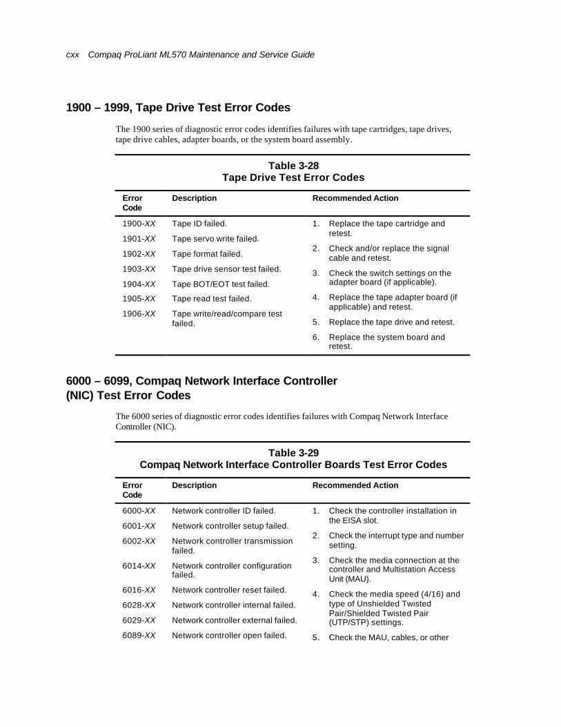
cxx Compaq ProLiant ML570 Maintenance and Service Guide
1900 – 1999, Tape Drive Test Error Codes
The 1900 series of diagnostic error codes identifies failures with tape cartridges, tape drives, tape drive cables, adapter boards, or the system board assembly.
Table 3-28 Tape Drive Test Error Codes
Error Code
Description Recommended Action
1900-XX Tape ID failed.
1901-XX Tape servo write failed.
1902-XX Tape format failed.
1903-XX Tape drive sensor test failed.
1904-XX Tape BOT/EOT test failed.
1905-XX Tape read test failed.
1906-XX Tape write/read/compare test failed.
1. Replace the tape cartridge and retest.
2. Check and/or replace the signal cable and retest.
3. Check the switch settings on the adapter board (if applicable).
4. Replace the tape adapter board (if applicable) and retest.
5. Replace the tape drive and retest.
6. Replace the system board and retest.
6000 – 6099, Compaq Network Interface Controller (NIC) Test Error Codes
The 6000 series of diagnostic error codes identifies failures with Compaq Network Interface Controller (NIC).
Table 3-29 Compaq Network Interface Controller Boards Test Error Codes
Error Code
Description Recommended Action
6000-XX Network controller ID failed.
6001-XX Network controller setup failed.
6002-XX Network controller transmission failed.
6014-XX Network controller configuration failed.
6016-XX Network controller reset failed.
6028-XX Network controller internal failed.
6029-XX Network controller external failed.
6089-XX Network controller open failed.
1. Check the controller installation in the EISA slot.
2. Check the interrupt type and number setting.
3. Check the media connection at the controller and Multistation Access Unit (MAU).
4. Check the media speed (4/16) and type of Unshielded Twisted Pair/Shielded Twisted Pair (UTP/STP) settings.
5. Check the MAU, cables, or other
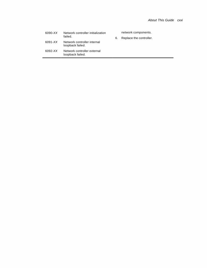
About This Guide cxxi
6090-XX Network controller initialization failed.
6091-XX Network controller internal loopback failed.
6092-XX Network controller external loopback failed.
network components.
6. Replace the controller.

cxxii Compaq ProLiant ML570 Maintenance and Service Guide
6500 – 6599, SCSI Hard Drive Test Error Codes
The 6500 series of diagnostic error codes identifies failures with SCSI hard drives, SCSI hard drive controller boards, SCSI hard drive cables, and system board functions. If the system uses a drive array controller, see “Array Diagnostic Utility (ADU)” later in this chapter.
Table 3-30 SCSI Hard Drive Test Error Codes
Error Code
Description Recommended Action
6500-XX SCSI disk ID drive types test failed.
6502-XX SCSI disk unconditional format test failed.
6505-XX SCSI disk read test failed.
6506-XX SCSI disk SA/media test failed.
6509-XX SCSI disk erase tape test failed.
6523-XX SCSI disk random read test failed.
6528-XX Media load/unload test failed.
1. Run the System Configuration Utility and verify the drive type.
2. Replace the SCSI disk drive signal and power cables, then retest.
3. Replace the SCSI controller and retest.
4. Replace the SCSI disk drive and retest.
5. Replace the system board and retest.
6600 – 6699, SCSI/IDE CD-ROM Drive Test Error Codes
The 6600 series of diagnostic error codes identifies failures with the CD-ROM drive cables, CD-ROM drives, adapter boards, or the system board assembly.
Table 3-31 SCSI/IDE CD-ROM Drive Test Error Codes
Error Code
Description Recommended Action
6600-XX CD-ROM ID failed.
6605-XX CD-ROM read failed.
1. Replace the CD-ROM media and retest.
2. Check and/or replace the signal cable and retest.
3. Check the switch settings on the adapter board (if applicable).
4. Replace the SCSI controller (if applicable) and retest.
5. Replace the CD-ROM drive and retest.
6. Replace the system board and retest.
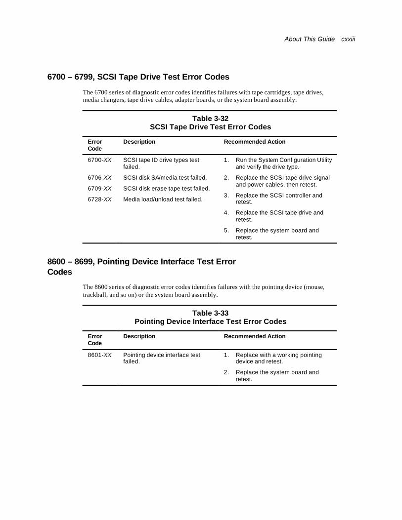
About This Guide cxxiii
6700 – 6799, SCSI Tape Drive Test Error Codes
The 6700 series of diagnostic error codes identifies failures with tape cartridges, tape drives, media changers, tape drive cables, adapter boards, or the system board assembly.
Table 3-32 SCSI Tape Drive Test Error Codes
Error Code
Description Recommended Action
6700-XX SCSI tape ID drive types test failed.
6706-XX SCSI disk SA/media test failed.
6709-XX SCSI disk erase tape test failed.
6728-XX Media load/unload test failed.
1. Run the System Configuration Utility and verify the drive type.
2. Replace the SCSI tape drive signal and power cables, then retest.
3. Replace the SCSI controller and retest.
4. Replace the SCSI tape drive and retest.
5. Replace the system board and retest.
8600 – 8699, Pointing Device Interface Test Error Codes
The 8600 series of diagnostic error codes identifies failures with the pointing device (mouse, trackball, and so on) or the system board assembly.
Table 3-33 Pointing Device Interface Test Error Codes
Error Code
Description Recommended Action
8601-XX Pointing device interface test failed.
1. Replace with a working pointing device and retest.
2. Replace the system board and retest.
cxxiv Compaq ProLiant ML570 Maintenance and Service Guide
Array Diagnostic Utility (ADU) The Array Diagnostic Utility (ADU) is a Windows-based software tool designed to run on all Compaq servers that support Compaq array controllers and are configured with SmartStart 4.10 or later. The two main functions of ADU are to collect all possible information about array controllers in the system and to generate a list of detected problems. The error messages and codes listed include all codes generated by Compaq products. The system generates only codes applicable to the configuration and options in the server.
ADU works by issuing multiple commands to the array controllers to determine if a problem exists. This data can then be saved to a file. In severe situations, this file can be sent to Compaq for analysis. In most cases, ADU provides enough information to initiate problem resolution immediately.
NOTE: ADU does not write to the drives, destroy data, or change or remove configuration information.
To start ADU:
9. Insert the SmartStart CD into the CD-ROM drive.
10. Restart the system from the SmartStart CD.
11. Select Array Diagnostic Utility (ADU) from the System Utilities menu.
A “Please Wait” panel displays, indicating that the ADU is identifying the system parameters. ADU gathers information from all array controllers in the system. The time it takes to gather this information depends on the size of the system. When the information gathering process is complete, the ADU displays the main screen or a panel indicating any problems detected.
CAUTION: Do not cycle the power during this process. The ADU must perform low-level operations that, if interrupted, could cause the controller to revert to a previous level of firmware if the firmware was soft-upgraded.
12. To generate an ADU report, select File, and then select Save Data from the Command menu.
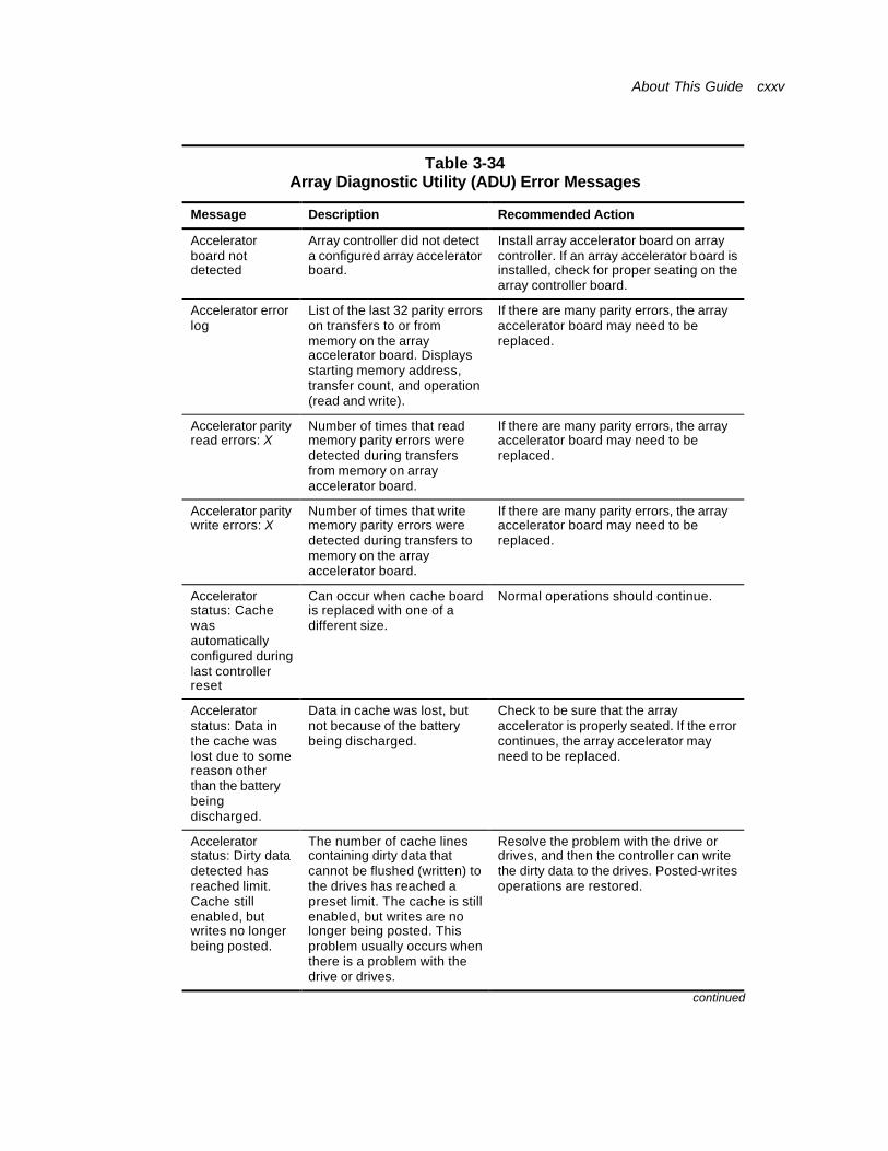
About This Guide cxxv
Table 3-34 Array Diagnostic Utility (ADU) Error Messages
Message Description Recommended Action
Accelerator board not detected
Array controller did not detect a configured array accelerator board.
Install array accelerator board on array controller. If an array accelerator board is installed, check for proper seating on the array controller board.
Accelerator error log
List of the last 32 parity errors on transfers to or from memory on the array accelerator board. Displays starting memory address, transfer count, and operation (read and write).
If there are many parity errors, the array accelerator board may need to be replaced.
Accelerator parity read errors: X
Number of times that read memory parity errors were detected during transfers from memory on array accelerator board.
If there are many parity errors, the array accelerator board may need to be replaced.
Accelerator parity write errors: X
Number of times that write memory parity errors were detected during transfers to memory on the array accelerator board.
If there are many parity errors, the array accelerator board may need to be replaced.
Accelerator status: Cache was automatically configured during last controller reset
Can occur when cache board is replaced with one of a different size.
Normal operations should continue.
Accelerator status: Data in the cache was lost due to some reason other than the battery being discharged.
Data in cache was lost, but not because of the battery being discharged.
Check to be sure that the array accelerator is properly seated. If the error continues, the array accelerator may need to be replaced.
Accelerator status: Dirty data detected has reached limit. Cache still enabled, but writes no longer being posted.
The number of cache lines containing dirty data that cannot be flushed (written) to the drives has reached a preset limit. The cache is still enabled, but writes are no longer being posted. This problem usually occurs when there is a problem with the drive or drives.
Resolve the problem with the drive or drives, and then the controller can write the dirty data to the drives. Posted-writes operations are restored.
continued
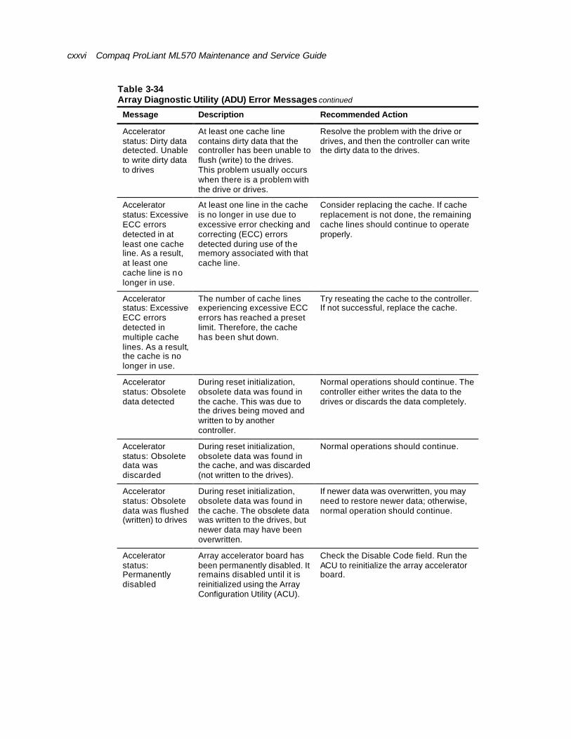
cxxvi Compaq ProLiant ML570 Maintenance and Service Guide
Table 3-34 Array Diagnostic Utility (ADU) Error Messages continued
Message Description Recommended Action
Accelerator status: Dirty data detected. Unable to write dirty data to drives
At least one cache line contains dirty data that the controller has been unable to flush (write) to the drives. This problem usually occurs when there is a problem with the drive or drives.
Resolve the problem with the drive or drives, and then the controller can write the dirty data to the drives.
Accelerator status: Excessive ECC errors detected in at least one cache line. As a result, at least one cache line is no longer in use.
At least one line in the cache is no longer in use due to excessive error checking and correcting (ECC) errors detected during use of the memory associated with that cache line.
Consider replacing the cache. If cache replacement is not done, the remaining cache lines should continue to operate properly.
Accelerator status: Excessive ECC errors detected in multiple cache lines. As a result, the cache is no longer in use.
The number of cache lines experiencing excessive ECC errors has reached a preset limit. Therefore, the cache has been shut down.
Try reseating the cache to the controller. If not successful, replace the cache.
Accelerator status: Obsolete data detected
During reset initialization, obsolete data was found in the cache. This was due to the drives being moved and written to by another controller.
Normal operations should continue. The controller either writes the data to the drives or discards the data completely.
Accelerator status: Obsolete data was discarded
During reset initialization, obsolete data was found in the cache, and was discarded (not written to the drives).
Normal operations should continue.
Accelerator status: Obsolete data was flushed (written) to drives
During reset initialization, obsolete data was found in the cache. The obsolete data was written to the drives, but newer data may have been overwritten.
If newer data was overwritten, you may need to restore newer data; otherwise, normal operation should continue.
Accelerator status: Permanently disabled
Array accelerator board has been permanently disabled. It remains disabled until it is reinitialized using the Array Configuration Utility (ACU).
Check the Disable Code field. Run the ACU to reinitialize the array accelerator board.
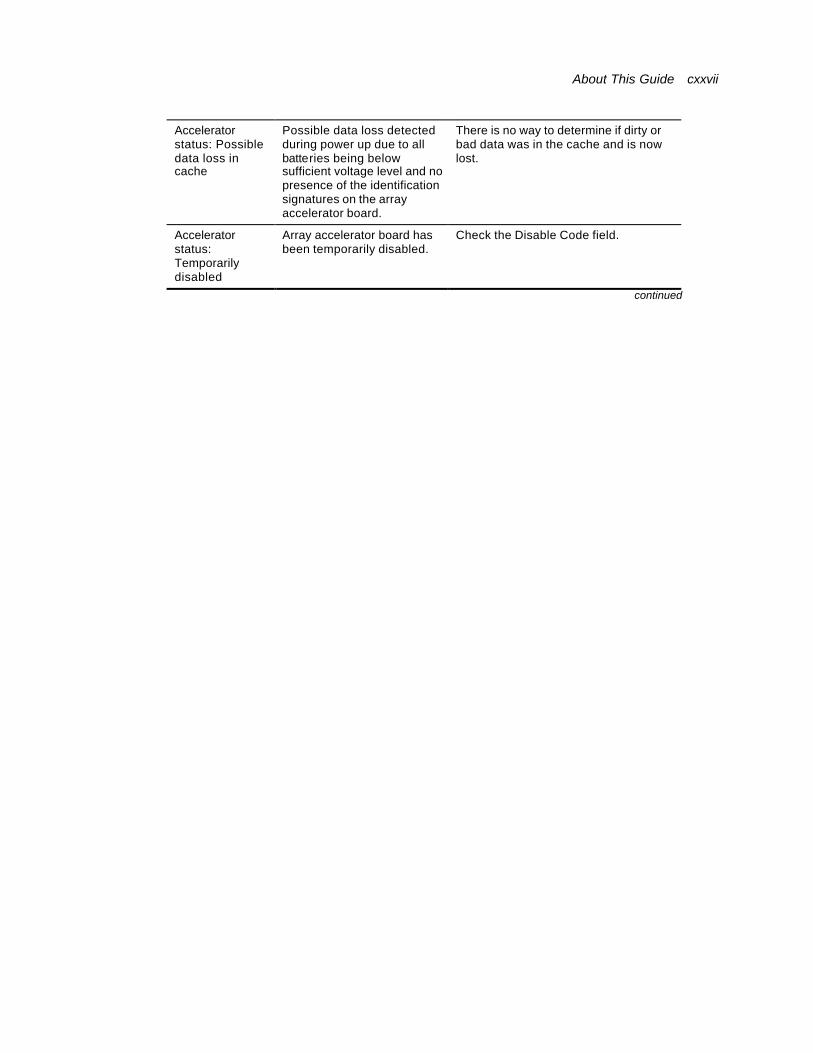
About This Guide cxxvii
Accelerator status: Possible data loss in cache
Possible data loss detected during power up due to all batteries being below sufficient voltage level and no presence of the identification signatures on the array accelerator board.
There is no way to determine if dirty or bad data was in the cache and is now lost.
Accelerator status: Temporarily disabled
Array accelerator board has been temporarily disabled.
Check the Disable Code field.
continued
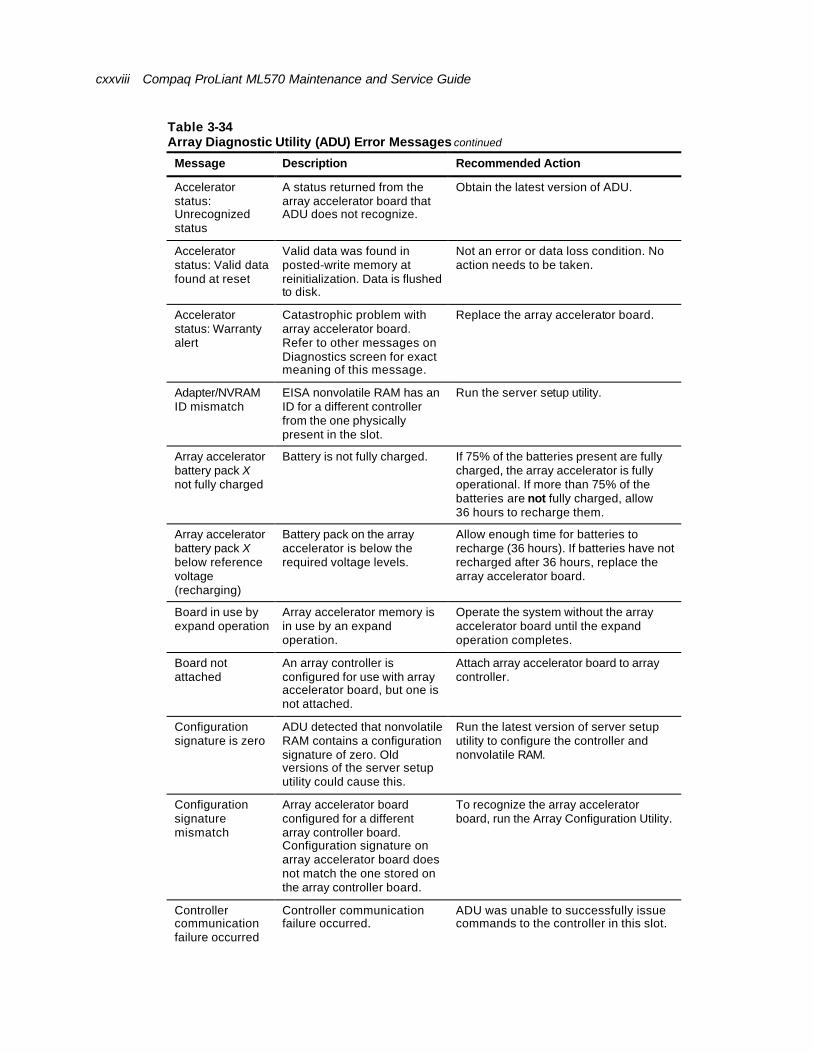
cxxviii Compaq ProLiant ML570 Maintenance and Service Guide
Table 3-34 Array Diagnostic Utility (ADU) Error Messages continued
Message Description Recommended Action
Accelerator status: Unrecognized status
A status returned from the array accelerator board that ADU does not recognize.
Obtain the latest version of ADU.
Accelerator status: Valid data found at reset
Valid data was found in posted-write memory at reinitialization. Data is flushed to disk.
Not an error or data loss condition. No action needs to be taken.
Accelerator status: Warranty alert
Catastrophic problem with array accelerator board. Refer to other messages on Diagnostics screen for exact meaning of this message.
Replace the array accelerator board.
Adapter/NVRAM ID mismatch
EISA nonvolatile RAM has an ID for a different controller from the one physically present in the slot.
Run the server setup utility.
Array accelerator battery pack X not fully charged
Battery is not fully charged. If 75% of the batteries present are fully charged, the array accelerator is fully operational. If more than 75% of the batteries are not fully charged, allow 36 hours to recharge them.
Array accelerator battery pack X below reference voltage (recharging)
Battery pack on the array accelerator is below the required voltage levels.
Allow enough time for batteries to recharge (36 hours). If batteries have not recharged after 36 hours, replace the array accelerator board.
Board in use by expand operation
Array accelerator memory is in use by an expand operation.
Operate the system without the array accelerator board until the expand operation completes.
Board not attached
An array controller is configured for use with array accelerator board, but one is not attached.
Attach array accelerator board to array controller.
Configuration signature is zero
ADU detected that nonvolatile RAM contains a configuration signature of zero. Old versions of the server setup utility could cause this.
Run the latest version of server setup utility to configure the controller and nonvolatile RAM.
Configuration signature mismatch
Array accelerator board configured for a different array controller board. Configuration signature on array accelerator board does not match the one stored on the array controller board.
To recognize the array accelerator board, run the Array Configuration Utility.
Controller communication failure occurred
Controller communication failure occurred.
ADU was unable to successfully issue commands to the controller in this slot.

About This Guide cxxix
Controller detected. NVRAM configuration not present
EISA nonvolatile RAM does not contain a configuration for this controller.
Run the server setup utility to configure the nonvolatile RAM.
continued
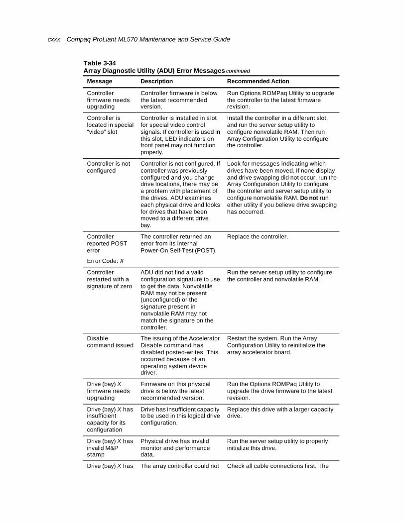
cxxx Compaq ProLiant ML570 Maintenance and Service Guide
Table 3-34 Array Diagnostic Utility (ADU) Error Messages continued
Message Description Recommended Action
Controller firmware needs upgrading
Controller firmware is below the latest recommended version.
Run Options ROMPaq Utility to upgrade the controller to the latest firmware revision.
Controller is located in special “video” slot
Controller is installed in s lot for special video control signals. If controller is used in this slot, LED indicators on front panel may not function properly.
Install the controller in a different slot, and run the server setup utility to configure nonvolatile RAM. Then run Array Configuration Utility to configure the controller.
Controller is not configured
Controller is not configured. If controller was previously configured and you change drive locations, there may be a problem with placement of the drives. ADU examines each physical drive and looks for drives that have been moved to a different drive bay.
Look for messages indicating which drives have been moved. If none display and drive swapping did not occur, run the Array Configuration Utility to configure the controller and server setup utility to configure nonvolatile RAM. Do not run either utility if you believe drive swapping has occurred.
Controller reported POST error
Error Code: X
The controller returned an error from its internal Power-On Self-Test (POST).
Replace the controller.
Controller restarted with a signature of zero
ADU did not find a valid configuration signature to use to get the data. Nonvolatile RAM may not be present (unconfigured) or the signature present in nonvolatile RAM may not match the signature on the controller.
Run the server setup utility to configure the controller and nonvolatile RAM.
Disable command issued
The issuing of the Accelerator Disable command has disabled posted-writes. This occurred because of an operating system device driver.
Restart the system. Run the Array Configuration Utility to reinitialize the array accelerator board.
Drive (bay) X firmware needs upgrading
Firmware on this physical drive is below the latest recommended version.
Run the Options ROMPaq Utility to upgrade the drive firmware to the latest revision.
Drive (bay) X has insufficient capacity for its configuration
Drive has insufficient capacity to be used in this logical drive configuration.
Replace this drive with a larger capacity drive.
Drive (bay) X has invalid M&P stamp
Physical drive has invalid monitor and performance data.
Run the server setup utility to properly initialize this drive.
Drive (bay) X has loose cable
The array controller could not communicate with this drive
Check all cable connections first. The cables could be bad, loose, or

About This Guide cxxxi
loose cable communicate with this drive at power up. This drive has not previously failed.
cables could be bad, loose, or disconnected. Power up the system and attempt to reconnect data/power cable to the drive. If this does not work, replace the cable. If it is still unsuccessful, the drive may need to be replaced.
Drive (bay) X is a replacement drive
This drive has been replaced. This message displays if a drive is replaced in a fault tolerant logical volume.
If the replacement was intentional, allow the drive to rebuild.
continued

cxxxii Compaq ProLiant ML570 Maintenance and Service Guide
Table 3-34 Array Diagnostic Utility (ADU) Error Messages continued
Message Description Recommended Action
Drive (bay) X is a replacement drive marked OK
This drive has been replaced and marked OK by the firmware. This may occur if a drive has an intermittent failure. For example, a drive has previously failed, then starts working again when ADU is run.
Replace the drive.
Drive (bay) X is failed.
The indicated physical drive has failed.
Replace the drive.
Drive (bay) X is undergoing drive recovery
This drive is being rebuilt from the corresponding mirror or parity data.
Normal operations should occur.
Drive (bay) X needs replacing
The 210-MB hard drive has firmware version 2.30 or 2.31.
Replace the drive.
Drive (bay) X upload code not readable
An error occurred while ADU was trying to read the upload code information from this drive.
If there were multiple errors, the drive may need to be replaced.
Drive (bay) X was inadvertently replaced
The physical drive was incorrectly replaced after another drive failed.
1. Replace the drive that was incorrectly replaced.
2. Replace the original drive that failed.
Do not run the server setup utility and try to reconfigure.
Drive Monitoring features are unobtainable
ADU is unable to receive monitor and performance data due to fatal command problem (such as drive time-out), or unable to receive data due to these features not being supported on the controller.
Check for other errors such as time-outs. If no other errors occur, upgrade the firmware to a version that supports the monitor and performance.
Drive Monitoring is NOT enabled for SCSI Port X Drive ID Y
The monitor and performance features have not been enabled on this drive.
Run the server setup utility to initialize the monitor and performance features.
Drive time-out occurred on physical drive bay X
ADU issued a command to a physical drive and the command was never acknowledged.
The drive or cable may be bad. Check the other error messages on the Diagnostics screen to determine resolution.
Drive X indicates position Y
Message indicates a designated physical drive, which shows it to be scrambled or in a drive bay other than the one for which it was originally configured.
Examine the graphical drive representation on ADU to determine proper drive locations. Remove drive X and place it in drive position Y. Rearrange the drives according to the ADU instructions.
continued
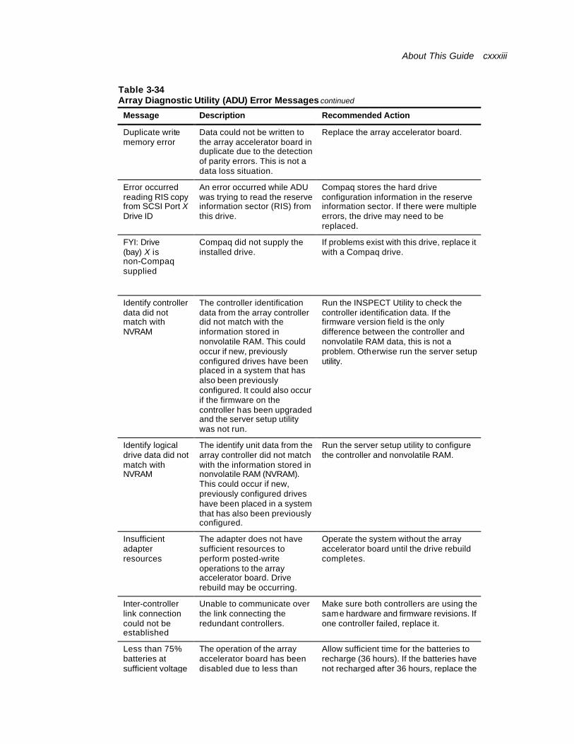
About This Guide cxxxiii
Table 3-34 Array Diagnostic Utility (ADU) Error Messages continued
Message Description Recommended Action
Duplicate write memory error
Data could not be written to the array accelerator board in duplicate due to the detection of parity errors. This is not a data loss situation.
Replace the array accelerator board.
Error occurred reading RIS copy from SCSI Port X Drive ID
An error occurred while ADU was trying to read the reserve information sector (RIS) from this drive.
Compaq stores the hard drive configuration information in the reserve information sector. If there were multiple errors, the drive may need to be replaced.
FYI: Drive (bay) X is non-Compaq supplied
Compaq did not supply the installed drive.
If problems exist with this drive, replace it with a Compaq drive.
Identify controller data did not match with NVRAM
The controller identification data from the array controller did not match with the information stored in nonvolatile RAM. This could occur if new, previously configured drives have been placed in a system that has also been previously configured. It could also occur if the firmware on the controller has been upgraded and the server setup utility was not run.
Run the INSPECT Utility to check the controller identification data. If the firmware version field is the only difference between the controller and nonvolatile RAM data, this is not a problem. Otherwise run the server setup utility.
Identify logical drive data did not match with NVRAM
The identify unit data from the array controller did not match with the information stored in nonvolatile RAM (NVRAM). This could occur if new, previously configured drives have been placed in a system that has also been previously configured.
Run the server setup utility to configure the controller and nonvolatile RAM.
Insufficient adapter resources
The adapter does not have sufficient resources to perform posted-write operations to the array accelerator board. Drive rebuild may be occurring.
Operate the system without the array accelerator board until the drive rebuild completes.
Inter-controller link connection could not be established
Unable to communicate over the link connecting the redundant controllers.
Make sure both controllers are using the same hardware and firmware revisions. If one controller failed, replace it.
Less than 75% batteries at sufficient voltage
The operation of the array accelerator board has been disabled due to less than
Allow sufficient time for the batteries to recharge (36 hours). If the batteries have not recharged after 36 hours, replace the

cxxxiv Compaq ProLiant ML570 Maintenance and Service Guide
sufficient voltage 75% of the battery packs being at the sufficient voltage level.
array accelerator board.
Less than 75% of batteries at sufficient voltage Battery pack X below reference voltage
Battery pack on the array accelerator is below the required voltage levels.
Allow enough time for batteries to recharge (36 hours). If batteries have not recharged after 36 hours, replace the array accelerator board.
continued
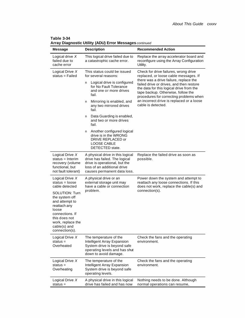
About This Guide cxxxv
Table 3-34 Array Diagnostic Utility (ADU) Error Messages continued
Message Description Recommended Action
Logical drive X failed due to cache error
This logical drive failed due to a catastrophic cache error.
Replace the array accelerator board and reconfigure using the Array Configuration Utility.
Logical Drive X status = Failed
This status could be issued for several reasons:
n Logical drive is configured for No Fault Tolerance and one or more drives fail.
n Mirroring is enabled, and any two mirrored drives fail.
n Data Guarding is enabled, and two or more drives fail.
n Another configured logical drive is in the WRONG DRIVE REPLACED or LOOSE CABLE DETECTED state.
Check for drive failures, wrong drive replaced, or loose cable messages. If there was a drive failure, replace the failed drive or drives, and then restore the data for this logical drive from the tape backup. Otherwise, follow the procedures for correcting problems when an incorrect drive is replaced or a loose cable is detected.
Logical Drive X status = Interim recovery (volume functional, but not fault tolerant)
A physical drive in this logical drive has failed. The logical drive is operational, but the loss of an additional drive causes permanent data loss.
Replace the failed drive as soon as possible.
Logical Drive X status = loose cable detected
SOLUTION: Turn the system off and attempt to reattach any loose connections. If this does not work, replace the cable(s) and connection(s).
A physical drive or an external storage unit may have a cable or connection problem.
Power down the system and attempt to reattach any loose connections. If this does not work, replace the cable(s) and connection(s).
Logical Drive X status = Overheated
The temperature of the Intelligent Array Expansion System drive is beyond safe operating levels and has shut down to avoid damage.
Check the fans and the operating environment.
Logical Drive X status = Overheating
The temperature of the Intelligent Array Expansion System drive is beyond safe operating levels.
Check the fans and the operating environment.
Logical Drive X status = Recovering
A physical drive in this logical drive has failed and has now been replaced. The replaced
Nothing needs to be done. Although normal operations can resume, performance is less than optimal until the

cxxxvi Compaq ProLiant ML570 Maintenance and Service Guide
Recovering
(rebuilding data on a replaced drive)
been replaced. The replaced drive is rebuilding from the mirror drive or the parity data.
performance is less than optimal until the rebuild process is complete.
continued
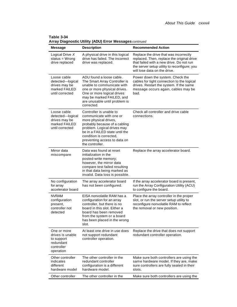
About This Guide cxxxvii
Table 3-34 Array Diagnostic Utility (ADU) Error Messages continued
Message Description Recommended Action
Logical Drive X status = Wrong drive replaced
A physical drive in this logical drive has failed. The incorrect drive was replaced.
Replace the drive that was incorrectly replaced. Then, replace the original drive that failed with a new drive. Do not run the server setup utility to reconfigure; you will lose data on the drive.
Loose cable detected—logical drives may be marked FAILED until corrected
ADU found a loose cable. The Smart Array Controller is unable to communicate with one or more physical drives. One or more logical drives may be marked FAILED, and are unusable until problem is corrected.
Power down the system. Check the cables for tight connection to the logical drives. Restart the system. If the same message occurs again, cables may be bad.
Loose cable detected—logical drives may be marked FAILED until corrected
Controller is unable to communicate with one or more physical drives, probably because of a cabling problem. Logical drives may be in a FAILED state until the condition is corrected, preventing access to data on the controller.
Check all controller and drive cable connections.
Mirror data miscompare
Data was found at reset initialization in the posted-write memory; however, the mirror data compare test failed resulting in that data being marked as invalid. Data loss is possible.
Replace the array accelerator board.
No configuration for array accelerator board
The array accelerator board has not been configured.
If the array accelerator board is present, run the Array Configuration Utility (ACU) to configure the board.
NVRAM configuration present, controller not detected
EISA nonvolatile RAM has a configuration for an array controller, but there is no board in this slot. Either a board has been removed from the system or a board has been placed in the wrong slot.
Place the array controller in the proper slot, or run the server setup utility to reconfigure nonvolatile RAM to reflect the removal or new position.
One or more drives is unable to support redundant controller operation
At least one drive in use does not support redundant controller operation.
Replace the drive that does not support redundant controller operation.
Other controller indicates different hardware model
The other controller in the redundant controller configuration is a different hardware model.
Make sure both controllers are using the same hardware model. If they are, make sure controllers are fully seated in their slots.
Other controller indicates
The other controller in the redundant controller
Make sure both controllers are using the same firmware revision.

cxxxviii Compaq ProLiant ML570 Maintenance and Service Guide
indicates different firmware version
redundant controller configuration is using a different firmware version.
same firmware revision.
continued
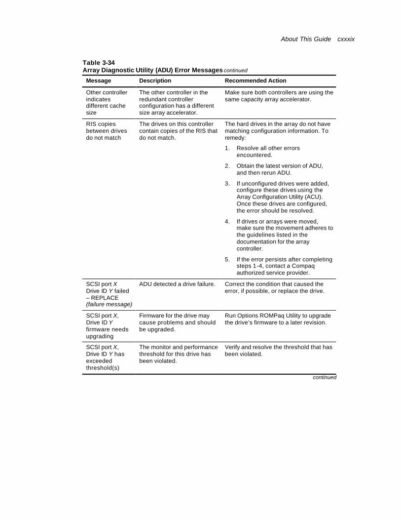
About This Guide cxxxix
Table 3-34 Array Diagnostic Utility (ADU) Error Messages continued
Message Description Recommended Action
Other controller indicates different cache size
The other controller in the redundant controller configuration has a different size array accelerator.
Make sure both controllers are using the same capacity array accelerator.
RIS copies between drives do not match
The drives on this controller contain copies of the RIS that do not match.
The hard drives in the array do not have matching configuration information. To remedy:
1. Resolve all other errors encountered.
2. Obtain the latest version of ADU, and then rerun ADU.
3. If unconfigured drives were added, configure these drives using the Array Configuration Utility (ACU). Once these drives are configured, the error should be resolved.
4. If drives or arrays were moved, make sure the movement adheres to the guidelines listed in the documentation for the array controller.
5. If the error persists after completing steps 1-4, contact a Compaq authorized service provider.
SCSI port X Drive ID Y failed – REPLACE (failure message)
ADU detected a drive failure. Correct the condition that caused the error, if possible, or replace the drive.
SCSI port X, Drive ID Y firmware needs upgrading
Firmware for the drive may cause problems and should be upgraded.
Run Options ROMPaq Utility to upgrade the drive’s firmware to a later revision.
SCSI port X, Drive ID Y has exceeded threshold(s)
The monitor and performance threshold for this drive has been violated.
Verify and resolve the threshold that has been violated.
continued
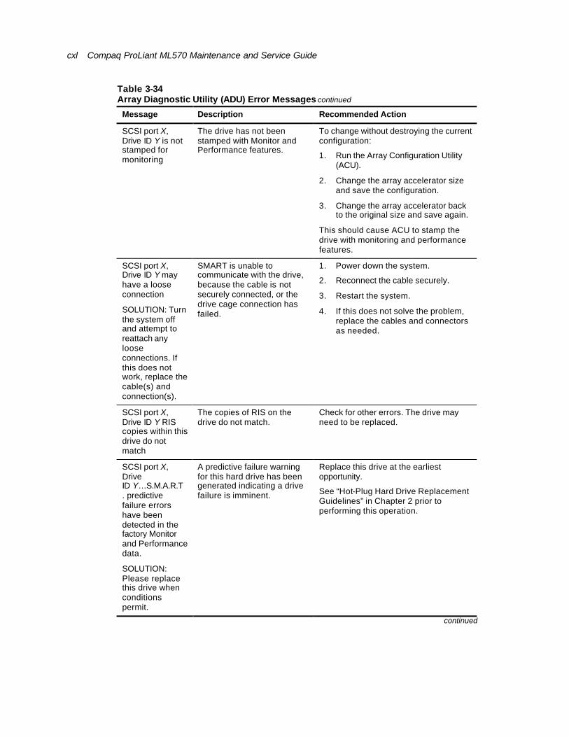
cxl Compaq ProLiant ML570 Maintenance and Service Guide
Table 3-34 Array Diagnostic Utility (ADU) Error Messages continued
Message Description Recommended Action
SCSI port X, Drive ID Y is not stamped for monitoring
The drive has not been stamped with Monitor and Performance features.
To change without destroying the current configuration:
1. Run the Array Configuration Utility (ACU).
2. Change the array accelerator size and save the configuration.
3. Change the array accelerator back to the original size and save again.
This should cause ACU to stamp the drive with monitoring and performance features.
SCSI port X, Drive ID Y may have a loose connection
SOLUTION: Turn the system off and attempt to reattach any loose connections. If this does not work, replace the cable(s) and connection(s).
SMART is unable to communicate with the drive, because the cable is not securely connected, or the drive cage connection has failed.
1. Power down the system.
2. Reconnect the cable securely.
3. Restart the system.
4. If this does not solve the problem, replace the cables and connectors as needed.
SCSI port X, Drive ID Y RIS copies within this drive do not match
The copies of RIS on the drive do not match.
Check for other errors. The drive may need to be replaced.
SCSI port X, Drive ID Y…S.M.A.R.T. predictive failure errors have been detected in the factory Monitor and Performance data.
SOLUTION: Please replace this drive when conditions permit.
A predictive failure warning for this hard drive has been generated indicating a drive failure is imminent.
Replace this drive at the earliest opportunity.
See “Hot-Plug Hard Drive Replacement Guidelines” in Chapter 2 prior to performing this operation.
continued
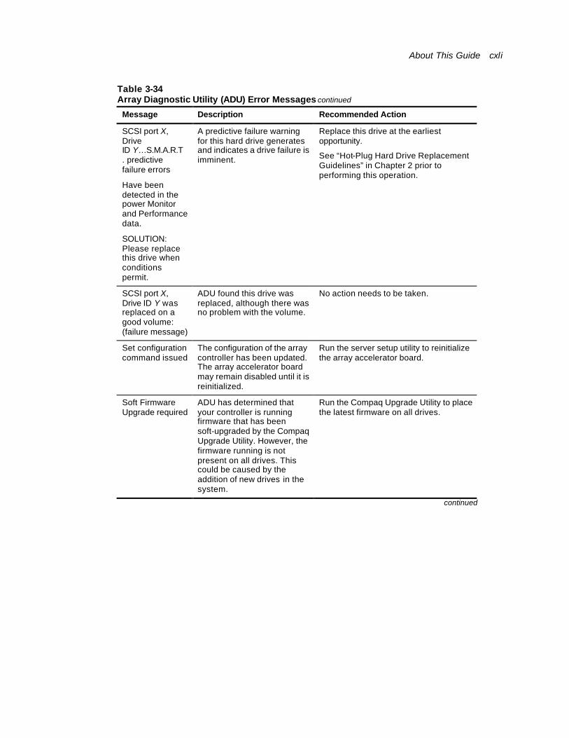
About This Guide cxli
Table 3-34 Array Diagnostic Utility (ADU) Error Messages continued
Message Description Recommended Action
SCSI port X, Drive ID Y…S.M.A.R.T. predictive failure errors
Have been detected in the power Monitor and Performance data.
SOLUTION: Please replace this drive when conditions permit.
A predictive failure warning for this hard drive generates and indicates a drive failure is imminent.
Replace this drive at the earliest opportunity.
See “Hot-Plug Hard Drive Replacement Guidelines” in Chapter 2 prior to performing this operation.
SCSI port X, Drive ID Y was replaced on a good volume: (failure message)
ADU found this drive was replaced, although there was no problem with the volume.
No action needs to be taken.
Set configuration command issued
The configuration of the array controller has been updated. The array accelerator board may remain disabled until it is reinitialized.
Run the server setup utility to reinitialize the array accelerator board.
Soft Firmware Upgrade required
ADU has determined that your controller is running firmware that has been soft-upgraded by the Compaq Upgrade Utility. However, the firmware running is not present on all drives. This could be caused by the addition of new drives in the system.
Run the Compaq Upgrade Utility to place the latest firmware on all drives.
continued
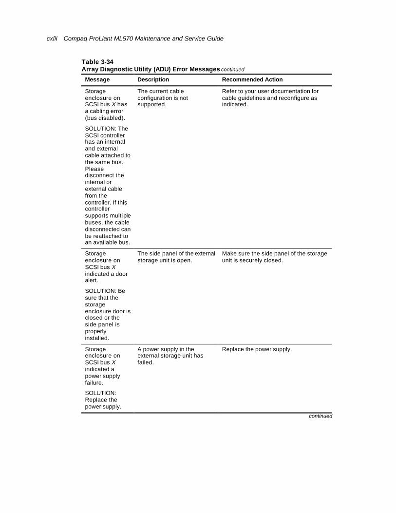
cxlii Compaq ProLiant ML570 Maintenance and Service Guide
Table 3-34 Array Diagnostic Utility (ADU) Error Messages continued
Message Description Recommended Action
Storage enclosure on SCSI bus X has a cabling error (bus disabled).
SOLUTION: The SCSI controller has an internal and external cable attached to the same bus. Please disconnect the internal or external cable from the controller. If this controller supports multiple buses, the cable disconnected can be reattached to an available bus.
The current cable configuration is not supported.
Refer to your user documentation for cable guidelines and reconfigure as indicated.
Storage enclosure on SCSI bus X indicated a door alert.
SOLUTION: Be sure that the storage enclosure door is closed or the side panel is properly installed.
The side panel of the external storage unit is open.
Make sure the side panel of the storage unit is securely closed.
Storage enclosure on SCSI bus X indicated a power supply failure.
SOLUTION: Replace the power supply.
A power supply in the external storage unit has failed.
Replace the power supply.
continued
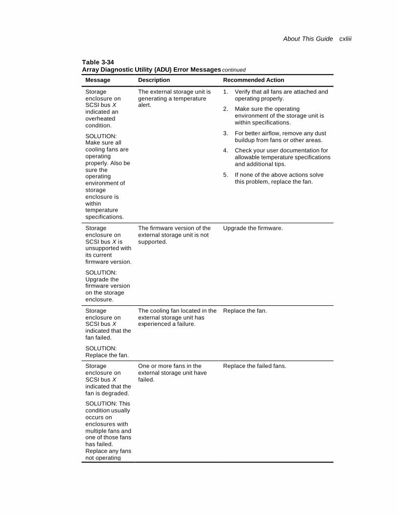
About This Guide cxliii
Table 3-34 Array Diagnostic Utility (ADU) Error Messages continued
Message Description Recommended Action
Storage enclosure on SCSI bus X indicated an overheated condition.
SOLUTION: Make sure all cooling fans are operating properly. Also be sure the operating environment of storage enclosure is within temperature specifications.
The external storage unit is generating a temperature alert.
1. Verify that all fans are attached and operating properly.
2. Make sure the operating environment of the storage unit is within specifications.
3. For better airflow, remove any dust buildup from fans or other areas.
4. Check your user documentation for allowable temperature specifications and additional tips.
5. If none of the above actions solve this problem, replace the fan.
Storage enclosure on SCSI bus X is unsupported with its current firmware version.
SOLUTION: Upgrade the firmware version on the storage enclosure.
The firmware version of the external storage unit is not supported.
Upgrade the firmware.
Storage enclosure on SCSI bus X indicated that the fan failed.
SOLUTION: Replace the fan.
The cooling fan located in the external storage unit has experienced a failure.
Replace the fan.
Storage enclosure on SCSI bus X indicated that the fan is degraded.
SOLUTION: This condition usually occurs on enclosures with multiple fans and one of those fans has failed. Replace any fans not operating
One or more fans in the external storage unit have failed.
Replace the failed fans.

cxliv Compaq ProLiant ML570 Maintenance and Service Guide
properly.
continued
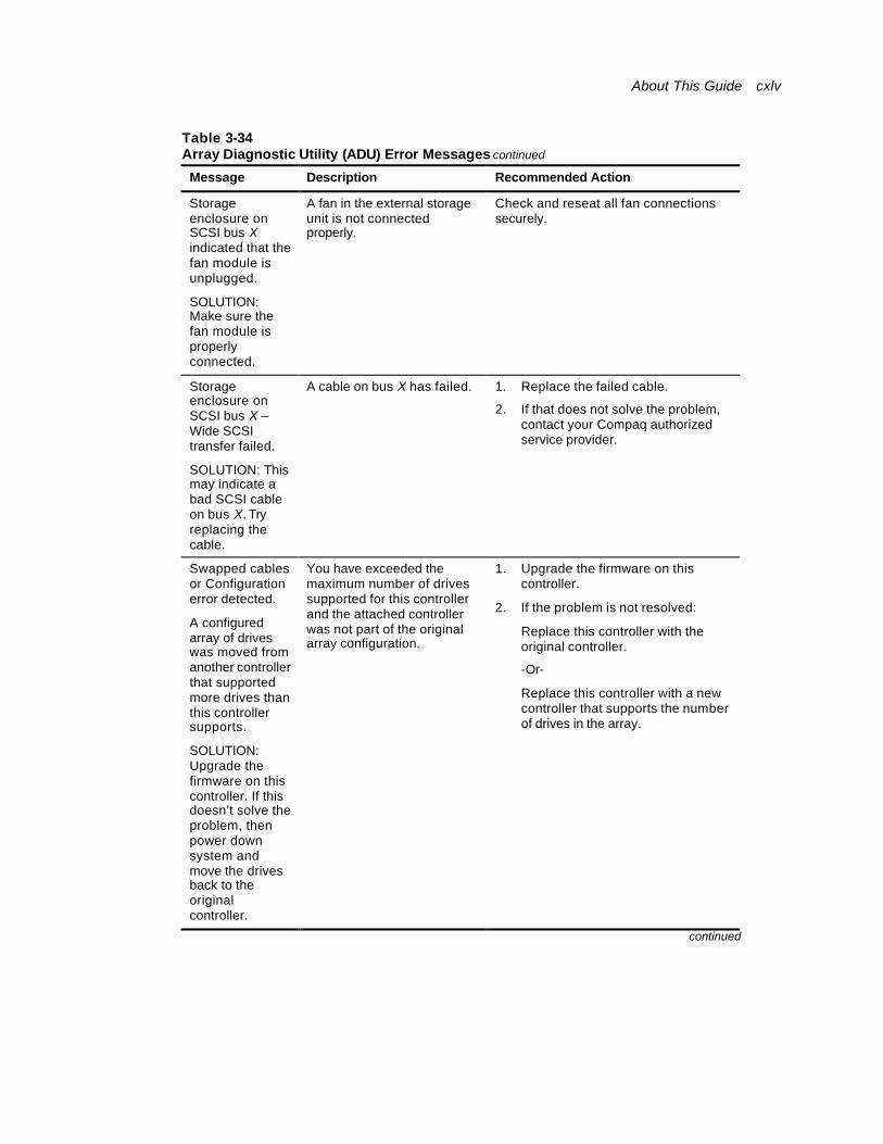
About This Guide cxlv
Table 3-34 Array Diagnostic Utility (ADU) Error Messages continued
Message Description Recommended Action
Storage enclosure on SCSI bus X indicated that the fan module is unplugged.
SOLUTION: Make sure the fan module is properly connected.
A fan in the external storage unit is not connected properly.
Check and reseat all fan connections securely.
Storage enclosure on SCSI bus X – Wide SCSI transfer failed.
SOLUTION: This may indicate a bad SCSI cable on bus X. Try replacing the cable.
A cable on bus X has failed. 1. Replace the failed cable.
2. If that does not solve the problem, contact your Compaq authorized service provider.
Swapped cables or Configuration error detected.
A configured array of drives was moved from another controller that supported more drives than this controller supports.
SOLUTION: Upgrade the firmware on this controller. If this doesn’t solve the problem, then power down system and move the drives back to the original controller.
You have exceeded the maximum number of drives supported for this controller and the attached controller was not part of the original array configuration.
1. Upgrade the firmware on this controller.
2. If the problem is not resolved:
Replace this controller with the original controller.
-Or-
Replace this controller with a new controller that supports the number of drives in the array.
continued

cxlvi Compaq ProLiant ML570 Maintenance and Service Guide
Table 3-34 Array Diagnostic Utility (ADU) Error Messages continued
Message Description Recommended Action
Swapped cables or Configuration error detected.
A drive rearrangement was attempted while an expand operation was running. This is an unsupported operation.
SOLUTION: Power down system then move drives back to their original location. Power on system and wait for the expand operation to complete before attempting a drive rearrangement.
One or more drive locations were changed while an expand operation was in progress.
1. Power down the server.
2. Place the drives back in their original locations.
3. Restart the server, and complete the expand operation.
4. Move the drives to their new locations after the expand operation is completed.
Swapped cables or Configuration error detected.
An unsupported drive arrangement was attempted.
SOLUTION: Power down system then move drives back to their original location.
One or more physical drives were moved, causing a configuration that is not supported.
Move all drives back to their original locations, and refer to your user documentation for supported configurations.
Swapped cables or Configuration error detected.
The cables appear to be interchanged.
SOLUTION: Power down system then move the drives or cables back to their original location.
ADU has detected a change in the cable configuration.
One or more cables may be attached to the incorrect bus.
-Or-
One or more drives have been moved to new locations.
Refer to your user documentation for supported configurations and cabling guidelines.
Restore to the original configuration.
continued
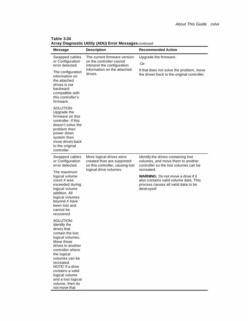
About This Guide cxlvii
Table 3-34 Array Diagnostic Utility (ADU) Error Messages continued
Message Description Recommended Action
Swapped cables or Configuration error detected.
The configuration information on the attached drives is not backward compatible with this controller’s firmware.
SOLUTION: Upgrade the firmware on this controller. If this doesn’t solve the problem then power down system then move drives back to the original controller.
The current firmware version on the controller cannot interpret the configuration information on the attached drives.
Upgrade the firmware.
-Or-
If that does not solve the problem, move the drives back to the original controller.
Swapped cables or Configuration error detected.
The maximum logical volume count X was exceeded during logical volume addition. All logical volumes beyond X have been lost and cannot be recovered.
SOLUTION: Identify the drives that contain the lost logical volumes. Move those drives to another controller where the logical volumes can be recreated. NOTE! If a drive contains a valid logical volume and a lost logical volume, then do not move that drive to another
More logical drives were created than are supported on this controller, causing lost logical drive volumes.
Identify the drives containing lost volumes, and move them to another controller so the lost volumes can be recreated.
WARNING: Do not move a drive if it also contains valid volume data. This process causes all valid data to be destroyed!

cxlviii Compaq ProLiant ML570 Maintenance and Service Guide
drive to another controller.
continued
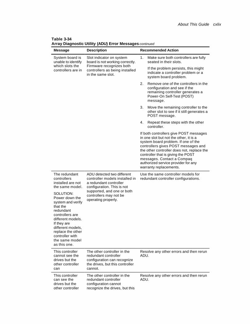
About This Guide cxlix
Table 3-34 Array Diagnostic Utility (ADU) Error Messages continued
Message Description Recommended Action
System board is unable to identify which slots the controllers are in
Slot indicator on system board is not working correctly. Firmware recognizes both controllers as being installed in the same slot.
1. Make sure both controllers are fully seated in their slots.
If the problem persists, this might indicate a controller problem or a system board problem.
2. Remove one of the controllers in the configuration and see if the remaining controller generates a Power-On Self-Test (POST) message.
3. Move the remaining controller to the other slot to see if it still generates a POST message.
4. Repeat these steps with the other controller.
If both controllers give POST messages in one slot but not the other, it is a system board problem. If one of the controllers gives POST messages and the other controller does not, replace the controller that is giving the POST messages. Contact a Compaq authorized service provider for any warranty replacements.
The redundant controllers installed are not the same model.
SOLUTION: Power down the system and verify that the redundant controllers are different models. If they are different models, replace the other controller with the same model as this one.
ADU detected two different controller models installed in a redundant controller configuration. This is not supported, and one or both controllers may not be operating properly.
Use the same controller models for redundant controller configurations.
This controller cannot see the drives but the other controller can
The other controller in the redundant controller configuration can recognize the drives, but this controller cannot.
Resolve any other errors and then rerun ADU.
This controller can see the drives but the other controller cannot
The other controller in the redundant controller configuration cannot recognize the drives, but this controller can.
Resolve any other errors and then rerun ADU.
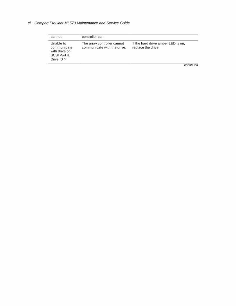
cl Compaq ProLiant ML570 Maintenance and Service Guide
cannot controller can.
Unable to communicate with drive on SCSI Port X, Drive ID Y
The array controller cannot communicate with the drive.
If the hard drive amber LED is on, replace the drive.
continued

About This Guide cli
Table 3-34 Array Diagnostic Utility (ADU) Error Messages continued
Message Description Recommended Action
Unable to retrieve identify controller data. Controller may be disabled or failed.
SOLUTION: Power down the system. Verify that the controller is fully seated. Then power the system on and look for helpful error messages displayed by the controller. If this doesn’t help, contact your COMPAQ service provider.
ADU requested the identify controller data from the controller but was unable to obtain it. This usually indicates that the controller is not seated properly or has failed.
1. Power down the server.
2. Verify the controller is fully seated.
3. Restart the server.
4. Resolve any error messages displayed by the controller.
If this does not solve the problem, contact a Compaq authorized service provider.
Unknown disable code
A code was returned from the array accelerator board that ADU does not recognize.
Obtain the latest version of ADU.
Unrecoverable read error
Read parity errors were detected when attempting to read the same data from both sides of the mirrored memory. Data loss occurs.
Replace the array accelerator board.
Warning bit detected
A monitor and performance threshold violation may have occurred. The status of a logical drive may not be OK.
Check the other error messages for an indication of the problem.
WARNING – Drive Write Cache is enabled on X
Drive has its internal write cache enabled. The drive may be a third-party drive or the operating parameters of the drive may have been altered. Condition may cause data corruption if power to the drive is interrupted.
Replace the drive with a Compaq drive, or restore the operating parameter of the drive.
continued
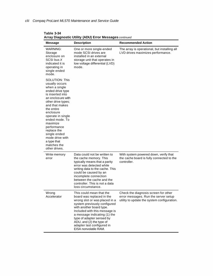
clii Compaq ProLiant ML570 Maintenance and Service Guide
Table 3-34 Array Diagnostic Utility (ADU) Error Messages continued
Message Description Recommended Action
WARNING: Storage enclosure on SCSI bus X indicated it is operating in single ended mode.
SOLUTION: This usually occurs when a single ended drive type is inserted into an enclosure with other drive types; and that makes the entire enclosure operate in single ended mode. To maximize performance replace the single ended mode drive with a type that matches the other drives.
One or more single-ended mode SCSI drives are installed in an external storage unit that operates in low voltage differential (LVD) mode.
The array is operational, but installing all LVD drives maximizes performance.
Write memory error
Data could not be written to the cache memory. This typically means that a parity error was detected while writing data to the cache. This could be caused by an incomplete connection between the cache and the controller. This is not a data loss circumstance.
With system powered down, verify that the cache board is fully connected to the controller.
Wrong Accelerator
This could mean that the board was replaced in the wrong slot or was placed in a system previously configured with another board type. Included with this message is a message indicating (1) the type of adapter sensed by ADU, and (2) the type of adapter last configured in EISA nonvolatile RAM.
Check the diagnosis screen for other error messages. Run the server setup utility to update the system configuration.
About This Guide cliii
Integrated Management Log (IML) On servers supporting the Integrated Management Display (IMD), the Compaq Integrated Management Log (IML) replaces the Critical Error Log and Correctable Memory Logs. IML records system events and stores them in an easily viewable form. Each event is marked with a time-stamp with one-minute granularity.
Events listed in the IML are categorized as one of four event severity levels:
n Status—indicates that the message is informational only.
n Repaired—indicates that corrective action has been taken.
n Caution—indicates a nonfatal error condition.
n Critical—indicates a component failure.
The IML requires Compaq operating system-dependent drivers. Refer to the Support Software CD for instructions on installing the appropriate drivers.
Refer to the setup and installation guide that comes with the server or to the Integrated Management Display User Guide provided with the IMD option kit.
Multiple Ways of Viewing the Information Management Log (IML)
You can view an event in the IML from within the:
n Integrated Management Display
n Compaq Insight Manager
n Compaq Survey Utility
n IML Management Utility
Integrated Management Display (IMD)
The IMD is an LCD panel that presents information directly at the server, assisting in diagnosing and servicing the server without a keyboard and monitor.
Compaq Insight Manager
Compaq Insight Manager is a comprehensive management tool used to monitor and control the operation of Compaq servers and clients. Compaq Insight Manager consists of two components: a Windows-based console application, and server- or client-based management data collection agents. Starting with Compaq Insight Manager 4.0, the agents for Microsoft Windows NT and Novell NetWare are also Web-enhanced; that is, these agents enable Web browser access and monitoring of management information.
The management agents monitor over 1,000 management parameters. Key subsystems are instrumented to make health, configuration, and performance data available to agent software. Agents act upon data by initiating information, such as statistics on network interface or storage subsystem performance.

cliv Compaq ProLiant ML570 Maintenance and Service Guide
Viewing the Event List
13. From Compaq Insight Manager, select the appropriate server, and then select View Device Data. The selected server displays, with buttons around its perimeter.
14. Select the Recovery button, and then select the Integrated Management Log.
15. If a failed component has been replaced, select the event from the list. Then select Mark Repaired for the failed component in the Insight Manager.
Printing the Event List
NOTE: You can only view the event list from the Recovery/Integrated Management Log screen as described above.
16. From the Compaq Insight Manager screen, select the appropriate server.
17. Select the Configuration button, then the Recovery button, and then Print.
Compaq Survey Utility
The Compaq Survey Utility is a serviceability tool available for Windows NT and NetWare. It delivers online-configuration capture and comparison to maximize server availability. It is delivered on the Compaq Management CD in the SmartStart package or is available on the Compaq website. Refer to the Compaq Management CD for information on installing and running the Compaq Survey Utility.
After running the Compaq Survey Utility, view the IML by loading the output of the utility (typically called “survey.txt”) into a text viewer such as Microsoft Notepad. The event list follows the system slot information. After opening the text file, print it using the print feature of the viewer.
Compaq IML Management Utility
The Compaq IML Management Utility is a DOS-based tool that gives you the offline ability to review, mark corrected, and print events from the IML. It is located on the SmartStart and Support Software CD. Refer to the SmartStart Installation for Servers poster, which ships with the server, for information on how to install and use the IML Management Utility.
OS IML Viewer
Windows NT and NetWare have OS-specific IML viewers that allow you to view the IML while the server is running and while you are at the server console.
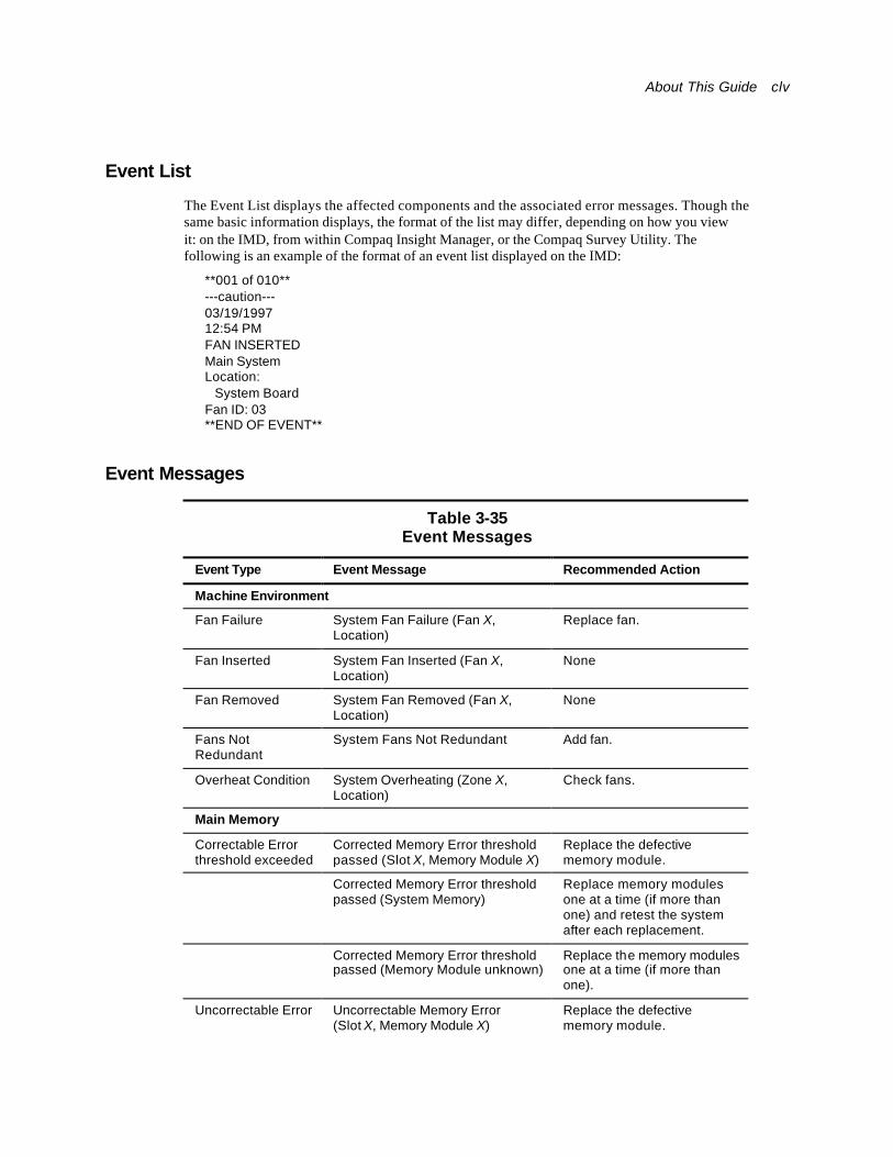
About This Guide clv
Event List
The Event List displays the affected components and the associated error messages. Though the same basic information displays, the format of the list may differ, depending on how you view it: on the IMD, from within Compaq Insight Manager, or the Compaq Survey Utility. The following is an example of the format of an event list displayed on the IMD:
**001 of 010** ---caution--- 03/19/1997 12:54 PM FAN INSERTED Main System Location: System Board Fan ID: 03 **END OF EVENT**
Event Messages
Table 3-35 Event Messages
Event Type Event Message Recommended Action
Machine Environment
Fan Failure System Fan Failure (Fan X, Location)
Replace fan.
Fan Inserted System Fan Inserted (Fan X, Location)
None
Fan Removed System Fan Removed (Fan X, Location)
None
Fans Not Redundant
System Fans Not Redundant Add fan.
Overheat Condition System Overheating (Zone X, Location)
Check fans.
Main Memory
Correctable Error threshold exceeded
Corrected Memory Error threshold passed (Slot X, Memory Module X)
Replace the defective memory module.
Corrected Memory Error threshold passed (System Memory)
Replace memory modules one at a time (if more than one) and retest the system after each replacement.
Corrected Memory Error threshold passed (Memory Module unknown)
Replace the memory modules one at a time (if more than one).
Uncorrectable Error Uncorrectable Memory Error (Slot X, Memory Module X)
Replace the defective memory module.
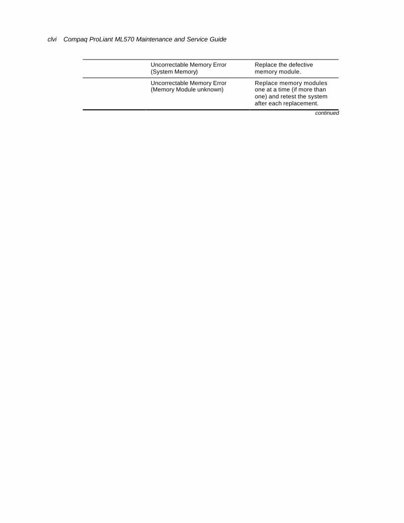
clvi Compaq ProLiant ML570 Maintenance and Service Guide
Uncorrectable Memory Error (System Memory)
Replace the defective memory module.
Uncorrectable Memory Error (Memory Module unknown)
Replace memory modules one at a time (if more than one) and retest the system after each replacement.
continued
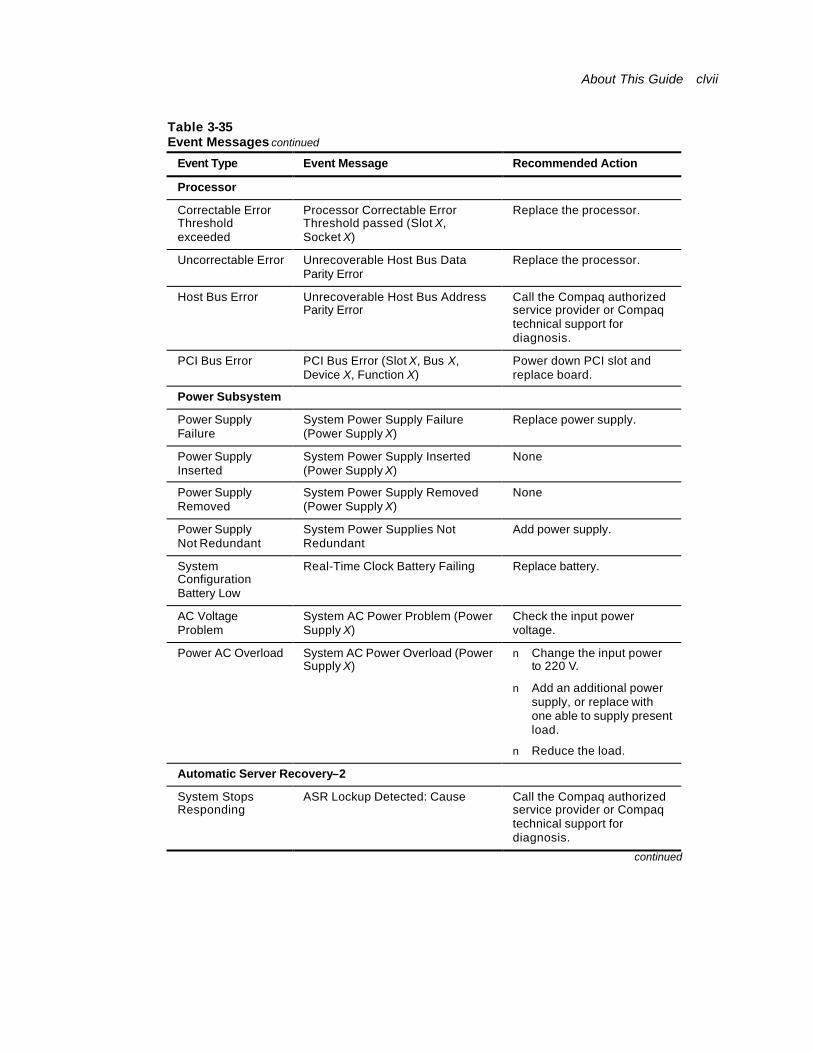
About This Guide clvii
Table 3-35 Event Messages continued
Event Type Event Message Recommended Action
Processor
Correctable Error Threshold exceeded
Processor Correctable Error Threshold passed (Slot X, Socket X)
Replace the processor.
Uncorrectable Error Unrecoverable Host Bus Data Parity Error
Replace the processor.
Host Bus Error Unrecoverable Host Bus Address Parity Error
Call the Compaq authorized service provider or Compaq technical support for diagnosis.
PCI Bus Error PCI Bus Error (Slot X, Bus X, Device X, Function X)
Power down PCI slot and replace board.
Power Subsystem
Power Supply Failure
System Power Supply Failure (Power Supply X)
Replace power supply.
Power Supply Inserted
System Power Supply Inserted (Power Supply X)
None
Power Supply Removed
System Power Supply Removed (Power Supply X)
None
Power Supply Not Redundant
System Power Supplies Not Redundant
Add power supply.
System Configuration Battery Low
Real-Time Clock Battery Failing Replace battery.
AC Voltage Problem
System AC Power Problem (Power Supply X)
Check the input power voltage.
Power AC Overload System AC Power Overload (Power Supply X)
n Change the input power to 220 V.
n Add an additional power supply, or replace with one able to supply present load.
n Reduce the load.
Automatic Server Recovery–2
System Stops Responding
ASR Lockup Detected: Cause Call the Compaq authorized service provider or Compaq technical support for diagnosis.
continued
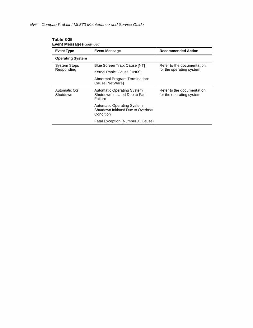
clviii Compaq ProLiant ML570 Maintenance and Service Guide
Table 3-35 Event Messages continued
Event Type Event Message Recommended Action
Operating System
Blue Screen Trap: Cause [NT]
Kernel Panic: Cause [UNIX]
System Stops Responding
Abnormal Program Termination: Cause [NetWare]
Refer to the documentation for the operating system.
Automatic Operating System Shutdown Initiated Due to Fan Failure
Automatic Operating System Shutdown Initiated Due to Overheat Condition
Automatic OS Shutdown
Fatal Exception (Number X, Cause)
Refer to the documentation for the operating system.
About This Guide clix
Rapid Error Recovery Compaq servers provide rapid recovery services for diagnosing and recovering from errors. These tools are available for local and remote diagnosis and recovery.
Rapid recovery means fast identification and resolution of complex faults. The Rapid Recovery Engine and Insight Management Agents notify the system administrator when a failure occurs, ensuring that the server experiences minimal downtime. You enable these features through the System Configuration Utility. These integrated server management features are:
n Automatic Server Recovery-2 (ASR-2)
n ASR-2 Integrated Management Log (IML) Messages
n Server Health Logs (on servers not supporting IMLs)
n Storage Fault Recovery Tracking
n Storage Automatic Reconstruction
n Network Interface Fault Recovery Tracking
n Memory Fault Recovery Tracking (with option upgrade kit)
These are discussed in more detail on the server documentation CD.
Automatic Server Recovery-2 (ASR-2)
Automatic Server Recovery-2 (ASR-2) allows the server to restart automatically from the operating system or the Compaq Utilities. To use this feature, you must use the System Configuration Utility to install Compaq Utilities in the system partition.
You can enable the ASR-2 feature to restart a server after a critical hardware or software error occurs. If a critical error occurs, the server records the error information in the IML, restarts the system, and then pages you. Using the System Configuration Utility, configure the system for automatic recovery or for attended local or remote access to diagnostic and configuration tools.
NOTE: ASR-2 is only available on operating systems using the ASR-2 drivers provided by Compaq.
You can also configure ASR-2 to page an administrator when the system restarts. ASR-2 depends on the application and driver that routinely notify the ASR-2 hardware of proper system operations. If the time between ASR-2 notifications exceeds the specified period, ASR-2 assumes a fault has occurred and initiates the recovery process.
To configure ASR-2:
18. Run the System Configuration Utility.
19. Select View, then Edit Details.
20. Set the software error recovery status to Enabled.
21. Set the software error recovery timeout.
clx Compaq ProLiant ML570 Maintenance and Service Guide
The available recovery features are:
n Software Error Recovery—automatically restarts the server after a software-induced server failure
n Environmental Recovery—allows the server to restart when temperature, fan, or AC power conditions return to normal
Unattended Recovery
For unattended recovery, ASR-2 performs the following actions:
n Logs the error information to the IML
n Resets the server
n Pages you (if a modem is present, and you selected Paging)
n Tries to restart the operating system
Often the server restarts successfully, making unattended recovery the ideal choice for remote locations where trained service personnel are not immediately available.
If ASR-2 cannot restart the server within 10 attempts, it places a critical error message in the IML, starts the server into Compaq Utilities, and enables remote access (if you configured remote access).
To use this level of ASR-2, you must configure ASR-2 to load the operating system after restart.
Attended Recovery
For attended recovery, ASR-2 performs the following actions:
n Logs the error information to the IML
n Resets the server
n Pages you (if a modem is present, and you selected Paging)
n Starts Compaq Utilities from the hard drive
n Enables remote access
During system configuration, these utilities are placed on the system utilities partition of the hard drive.
If you have configured for Dial-In access and have a modem with an auto-answer feature installed, you can dial in and remotely diagnose or reconfigure the server.
If you have configured the Compaq Utilities for network access, you can access the utilities over the network. You can use Compaq Insight Manager for dial-in or network access.
About This Guide clxi
Hardware Requirements
To use this level of ASR-2 over a modem, you need the following:
n A third-party PCI or optional Hayes modem
n System Configuration Utility and Diagnostics Utility installed on the system partition of the hard drive
n ASR-2 configured to load Compaq Utilities after restart
Remote Operations
To run Compaq Utilities remotely over an IPX using the Network feature, you need Compaq Insight Manager 2.0 or later or an NVT (Novell Virtual Terminal) Terminal Emulator with VT100 or ANSI terminal capabilities.
To run Compaq Utilities remotely over an IP network, you need Compaq Insight Manager 2.10 or later or a Telnet Terminal Emulator with VT100 or ANSI capabilities. If you are notified that ASR-2 restarted the server and you have restarted to Compaq Utilities, use the INSPECT Utility or Compaq Insight Manager to view the critical error in the Critical Error Log. Run Diagnostics to diagnose and resolve the problem.
Automatic Server Recovery (ASR-2)–Other Uses
You can configure ASR-2 to restart the server into Compaq Utilities to diagnose the critical error or to start the operating system to return the server to operational status as rapidly as possible.
When you enable ASR-2 to start the operating system, the server tries to start from the primary partition. In this mode, ASR-2 can page you if a critical error occurs, but you cannot access Compaq Utilities.
When you enable ASR-2 to start Compaq Utilities, the server restarts after a critical error and loads Compaq Utilities from the system partition onto the hard drive.
Starting Compaq Utilities
You can configure the server to start Compaq Utilities in four different ways:
n Without remote console support; for example, to run Compaq Utilities from the server console only
n With remote console support using modems for dial-in access
n With remote console support using a modem to dial a predetermined telephone number
n With remote console support through a network connection (IP or IPX)
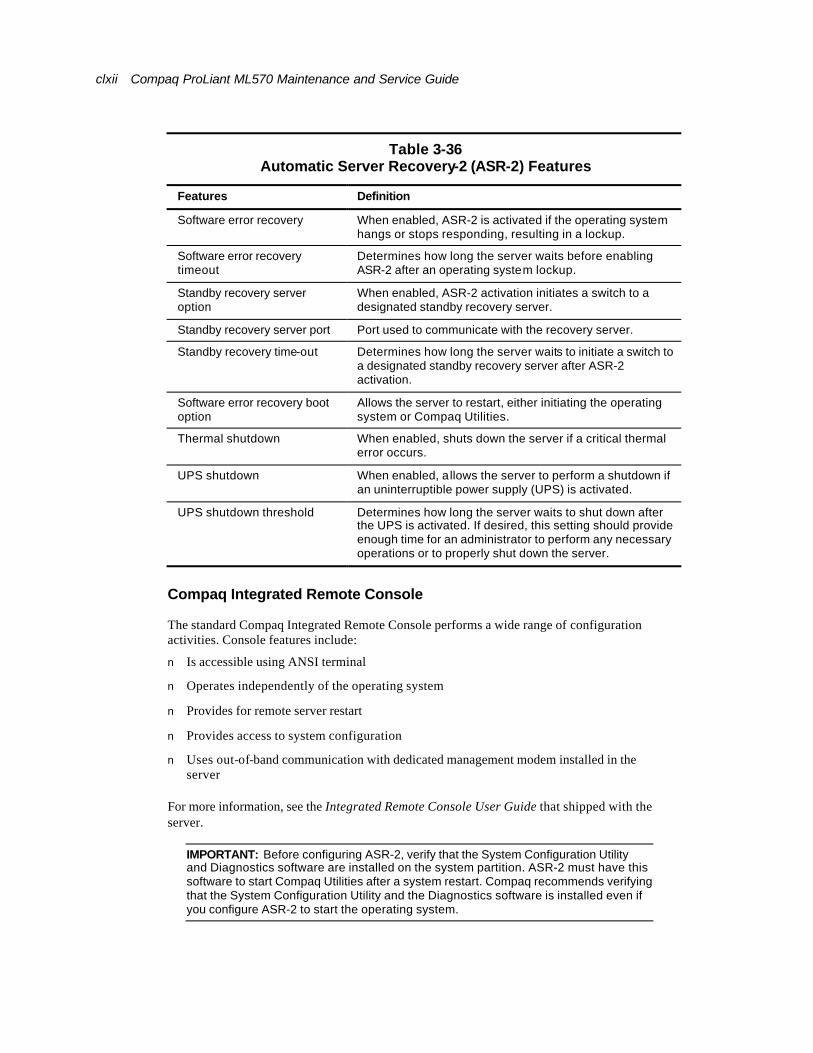
clxii Compaq ProLiant ML570 Maintenance and Service Guide
Table 3-36 Automatic Server Recovery-2 (ASR-2) Features
Features Definition
Software error recovery When enabled, ASR-2 is activated if the operating system hangs or stops responding, resulting in a lockup.
Software error recovery timeout
Determines how long the server waits before enabling ASR-2 after an operating system lockup.
Standby recovery server option
When enabled, ASR-2 activation initiates a switch to a designated standby recovery server.
Standby recovery server port Port used to communicate with the recovery server.
Standby recovery time-out Determines how long the server waits to initiate a switch to a designated standby recovery server after ASR-2 activation.
Software error recovery boot option
Allows the server to restart, either initiating the operating system or Compaq Utilities.
Thermal shutdown When enabled, shuts down the server if a critical thermal error occurs.
UPS shutdown When enabled, allows the server to perform a shutdown if an uninterruptible power supply (UPS) is activated.
UPS shutdown threshold Determines how long the server waits to shut down after the UPS is activated. If desired, this setting should provide enough time for an administrator to perform any necessary operations or to properly shut down the server.
Compaq Integrated Remote Console
The standard Compaq Integrated Remote Console performs a wide range of configuration activities. Console features include:
n Is accessible using ANSI terminal
n Operates independently of the operating system
n Provides for remote server restart
n Provides access to system configuration
n Uses out-of-band communication with dedicated management modem installed in the server
For more information, see the Integrated Remote Console User Guide that shipped with the server.
IMPORTANT: Before configuring ASR-2, verify that the System Configuration Utility and Diagnostics software are installed on the system partition. ASR-2 must have this software to start Compaq Utilities after a system restart. Compaq recommends verifying that the System Configuration Utility and the Diagnostics software is installed even if you configure ASR-2 to start the operating system.

About This Guide clxiii
Compaq Health Driver
The Compaq Health Driver continually resets the ASR-2 timer according to the frequency specified in the System Configuration Utility (for example, 10 minutes). If the ASR-2 timer counts down to zero before being reset, due to an operating system or a server lockup, ASR-2 restarts the server into either Compaq Utilities or the operating system (as indicated by the System Configuration parameters). The default value is 10 minutes. The allowable settings are 5, 10, 20, and 30 minutes.
For remote and offsite (unattended) servers, setting the software error recovery timeout for 5 minutes reduces server downtime and allows the server to recover quickly. For local (attended) servers located onsite, you can set the software error recovery timeout for 20 or 30 minutes, giving you time to arrive at the server if you wish to manually diagnose the problem.
The Compaq Health Driver is independent of the ASR-2 timer. Load the health driver and enable the ASR-2 timer. Enabling the ASR-2 timer allows the driver to detect and log information into the IML regarding numerous hardware and software errors. However, you cannot enable the ASR-2 timer without loading the Compaq Health Driver.
Before ASR-2 restarts the server, it records any information available about the condition of the operating system in the Critical Error Log or the IML depending on the server support. This information can be used to diagnose an operating system crash or server lockup, while still allowing the server to be restarted.
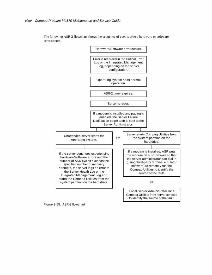
clxiv Compaq ProLiant ML570 Maintenance and Service Guide
The following ASR-2 flowchart shows the sequence of events after a hardware or software error occurs:
Hardware/Software error occurs.
Error is recorded in the Critical Error Log or the Integrated Management
Log, depending on the server configuration.
Operating system halts normal operation.
ASR-2 timer expires.
Server is reset.
If a modem is installed and paging is enabled, the Server Failure
Notification pager alert is sent to the Server Administrator.
Unattended server starts the operating system. Or
Server starts Compaq Utilities from the system partition on the
hard drive.
If a modem is installed, ASR puts the modem on auto-answer so that the server administrator can dial in (using third-party terminal emulator
software) to remotely run the Compaq Utilities to identify the
source of the fault.
If the server continues experiencing hardware/software errors and the number of ASR cycles exceeds the
specified number of recovery attempts, the server logs an error to
the Server Health Log or the Integrated Management Log and
starts the Compaq Utilities from the system partition on the hard drive.
Or
Local Server Administrator runs Compaq Utilities from server console
to identify the source of the fault.
Figure 3-55. ASR-2 flowchart
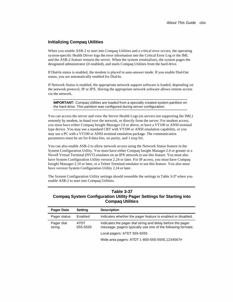
About This Guide clxv
Initializing Compaq Utilities
When you enable ASR-2 to start into Compaq Utilities and a critical error occurs, the operating system-specific Health Driver logs the error information into the Critical Error Log or the IML and the ASR-2 feature restarts the server. When the system reinitializes, the system pages the designated administrator (if enabled), and starts Compaq Utilities from the hard drive.
If Dial-In status is enabled, the modem is placed in auto-answer mode. If you enable Dial-Out status, you are automatically enabled for Dial-In.
If Network Status is enabled, the appropriate network support software is loaded, depending on the network protocol, IP or IPX. Having the appropriate network software allows remote access via the network.
IMPORTANT: Compaq Utilities are loaded from a specially created system partition on the hard drive. This partition was configured during server configuration.
You can access the server and view the Server Health Logs (in servers not supporting the IML) remotely by modem, in-band over the network, or directly from the server. For modem access, you must have either Compaq Insight Manager 2.0 or above, or have a VT100 or ANSI terminal type device. You may use a standard CRT with VT100 or ANSI emulation capability, or you may use a PC with a VT100 or ANSI terminal emulation package. The communication parameters must be set for 8 data bits, no parity, and 1 stop bit.
You can also enable ASR-2 to allow network access using the Network Status feature in the System Configuration Utility. You must have either Compaq Insight Manager 2.0 or greater or a Novell Virtual Terminal (NVT) emulator on an IPX network to use this feature. You must also have System Configuration Utility version 2.24 or later. For IP access, you must have Compaq Insight Manager 2.10 or later, or a Telnet Terminal emulator to use this feature. You also must have version System Configuration Utility 2.24 or later.
The System Configuration Utility settings should resemble the settings in Table 3-37 when you enable ASR-2 to start into Compaq Utilities.
Table 3-37 Compaq System Configuration Utility Pager Settings for Starting into
Compaq Utilities
Pager Data Setting Description
Pager status Enabled Indicates whether the pager feature is enabled or disabled.
Pager dial string
ATDT 555-5555
Indicates the pager dial string and delay before the pager message; pagers typically use one of the following formats:
Local pagers: ATDT 555-5555
Wide area pagers: ATDT 1-800-555-5555,1234567#
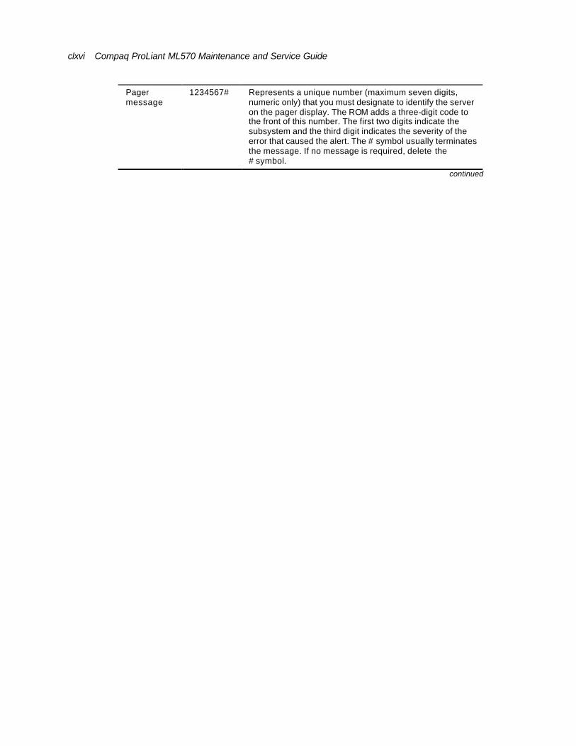
clxvi Compaq ProLiant ML570 Maintenance and Service Guide
Pager message
1234567# Represents a unique number (maximum seven digits, numeric only) that you must designate to identify the server on the pager display. The ROM adds a three-digit code to the front of this number. The first two digits indicate the subsystem and the third digit indicates the severity of the error that caused the alert. The # symbol usually terminates the message. If no message is required, delete the # symbol.
continued
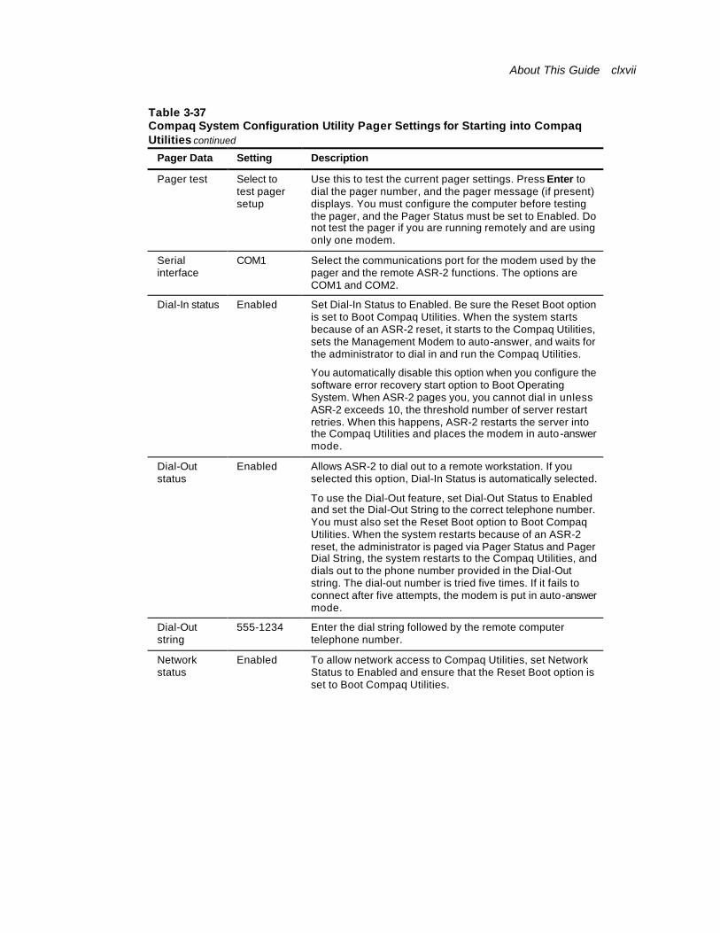
About This Guide clxvii
Table 3-37 Compaq System Configuration Utility Pager Settings for Starting into Compaq Utilities continued
Pager Data Setting Description
Pager test Select to test pager setup
Use this to test the current pager settings. Press Enter to dial the pager number, and the pager message (if present) displays. You must configure the computer before testing the pager, and the Pager Status must be set to Enabled. Do not test the pager if you are running remotely and are using only one modem.
Serial interface
COM1 Select the communications port for the modem used by the pager and the remote ASR-2 functions. The options are COM1 and COM2.
Dial-In status Enabled Set Dial-In Status to Enabled. Be sure the Reset Boot option is set to Boot Compaq Utilities. When the system starts because of an ASR-2 reset, it starts to the Compaq Utilities, sets the Management Modem to auto-answer, and waits for the administrator to dial in and run the Compaq Utilities.
You automatically disable this option when you configure the software error recovery start option to Boot Operating System. When ASR-2 pages you, you cannot dial in unless ASR-2 exceeds 10, the threshold number of server restart retries. When this happens, ASR-2 restarts the server into the Compaq Utilities and places the modem in auto-answer mode.
Dial-Out status
Enabled Allows ASR-2 to dial out to a remote workstation. If you selected this option, Dial-In Status is automatically selected.
To use the Dial-Out feature, set Dial-Out Status to Enabled and set the Dial-Out String to the correct telephone number. You must also set the Reset Boot option to Boot Compaq Utilities. When the system restarts because of an ASR-2 reset, the administrator is paged via Pager Status and Pager Dial String, the system restarts to the Compaq Utilities, and dials out to the phone number provided in the Dial-Out string. The dial-out number is tried five times. If it fails to connect after five attempts, the modem is put in auto-answer mode.
Dial-Out string
555-1234 Enter the dial string followed by the remote computer telephone number.
Network status
Enabled To allow network access to Compaq Utilities, set Network Status to Enabled and ensure that the Reset Boot option is set to Boot Compaq Utilities.
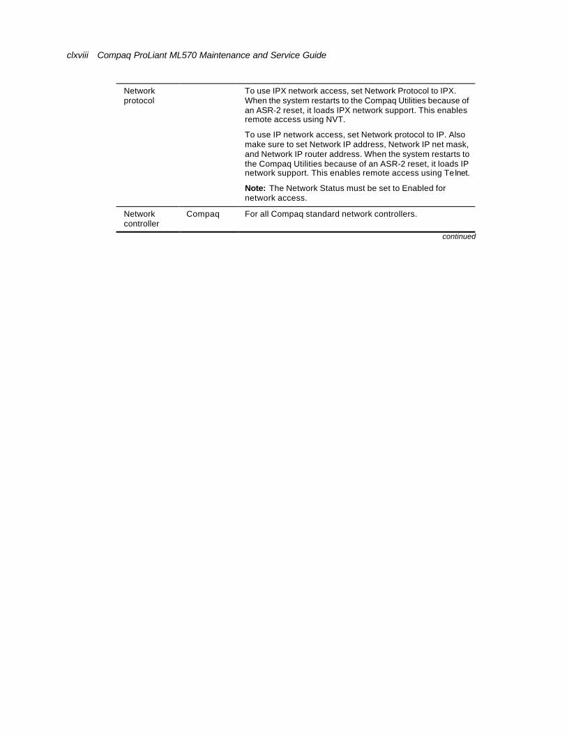
clxviii Compaq ProLiant ML570 Maintenance and Service Guide
Network protocol
To use IPX network access, set Network Protocol to IPX. When the system restarts to the Compaq Utilities because of an ASR-2 reset, it loads IPX network support. This enables remote access using NVT.
To use IP network access, set Network protocol to IP. Also make sure to set Network IP address, Network IP net mask, and Network IP router address. When the system restarts to the Compaq Utilities because of an ASR-2 reset, it loads IP network support. This enables remote access using Telnet.
Note: The Network Status must be set to Enabled for network access.
Network controller
Compaq For all Compaq standard network controllers.
continued

About This Guide clxix
Table 3-37 Compaq System Configuration Utility Pager Settings for Starting into Compaq Utilities continued
Pager Data Setting Description
Network host name
CPQHOU Enter the network name of the server. Use underscores instead of spaces within the name—for example, Compaq_Server. If you are using IPX network access to the Compaq Utilities, this server name is used to advertise NVT host services. This server name displays in the Compaq Insight Manager server list when the program determines it can communicate using NVT. Set this name to be the same as the server name you assign when the host OS is running.
Network Interface Controller (NIC) slot
Slot # Select the slot number of the NIC you wish to use for network access to Compaq Utilities.
Network frame type
ETHERNET_I I
Select the frame type for the network. Selections include both Ethernet and Token-Ring topologies.
Network IP address
Enter the IP address for this server in standard dot notation.
Note: This is not used if you select Custom for Network controller. You must enter the IP address into the NET.CFG file that you load into the system partition.
Network IP net mask
Enter the net mask for this server in standard dot notation.
Note: This is not used if you select Custom for network controller. You must enter the IP address into the NET.CFG file that you load into the system partition.
Network IP router address
Enter the router to be used for this server in standard dot notation.
Note: This is not used if you select Custom for network controller. You must enter the IP address into the NET.CFG file that you load into the system partition.
If you configure the server to restart, and then access the Compaq Utilities menu, it prepares for remote communications. You can run Compaq Diagnostics, INSPECT, or the server-setup utility remotely by using a workstation running terminal emulation software, such as Compaq Insight Manager.
Initializing the Operating System
When you enable ASR-2 to restart into the operating system and a critical error occurs, ASR-2 logs the error into the Critical Error Log or IML, and restarts the server. The system ROM pages the designated administrator, then executes the normal restart process.
IMPORTANT: When you enable ASR-2 to restart into the operating system, Modem Dial-In Status, Network Status, and Modem Dial-Out Status are automatically disabled. In this mode, ASR-2 can page you if a critical error occurs, but you cannot access the server, and the server cannot dial out to a remote workstation.
If the ASR-2 feature cannot restart the server within 10 attempts, it logs a critical error into the Critical Error Log or IML restarts the server into the Compaq Utilities, and puts the modem into auto-answer mode.
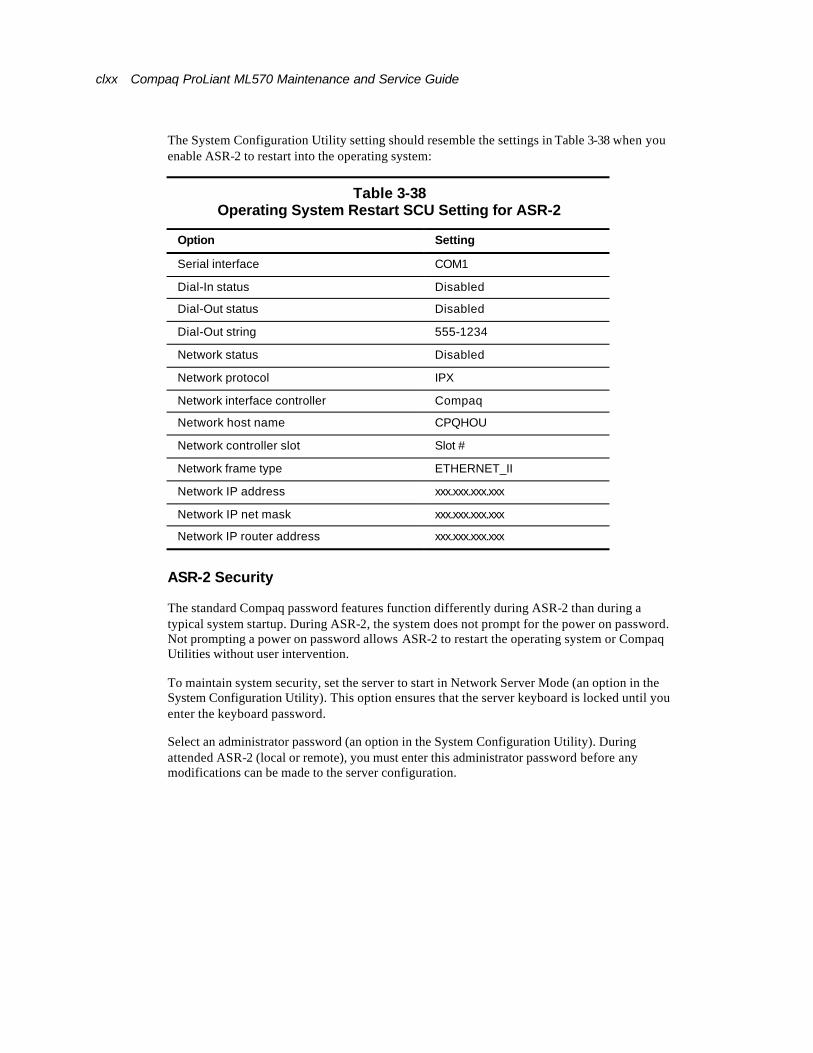
clxx Compaq ProLiant ML570 Maintenance and Service Guide
The System Configuration Utility setting should resemble the settings in Table 3-38 when you enable ASR-2 to restart into the operating system:
Table 3-38 Operating System Restart SCU Setting for ASR-2
Option Setting
Serial interface COM1
Dial-In status Disabled
Dial-Out status Disabled
Dial-Out string 555-1234
Network status Disabled
Network protocol IPX
Network interface controller Compaq
Network host name CPQHOU
Network controller slot Slot #
Network frame type ETHERNET_II
Network IP address xxx.xxx.xxx.xxx
Network IP net mask xxx.xxx.xxx.xxx
Network IP router address xxx.xxx.xxx.xxx
ASR-2 Security
The standard Compaq password features function differently during ASR-2 than during a typical system startup. During ASR-2, the system does not prompt for the power on password. Not prompting a power on password allows ASR-2 to restart the operating system or Compaq Utilities without user intervention.
To maintain system security, set the server to start in Network Server Mode (an option in the System Configuration Utility). This option ensures that the server keyboard is locked until you enter the keyboard password.
Select an administrator password (an option in the System Configuration Utility). During attended ASR-2 (local or remote), you must enter this administrator password before any modifications can be made to the server configuration.
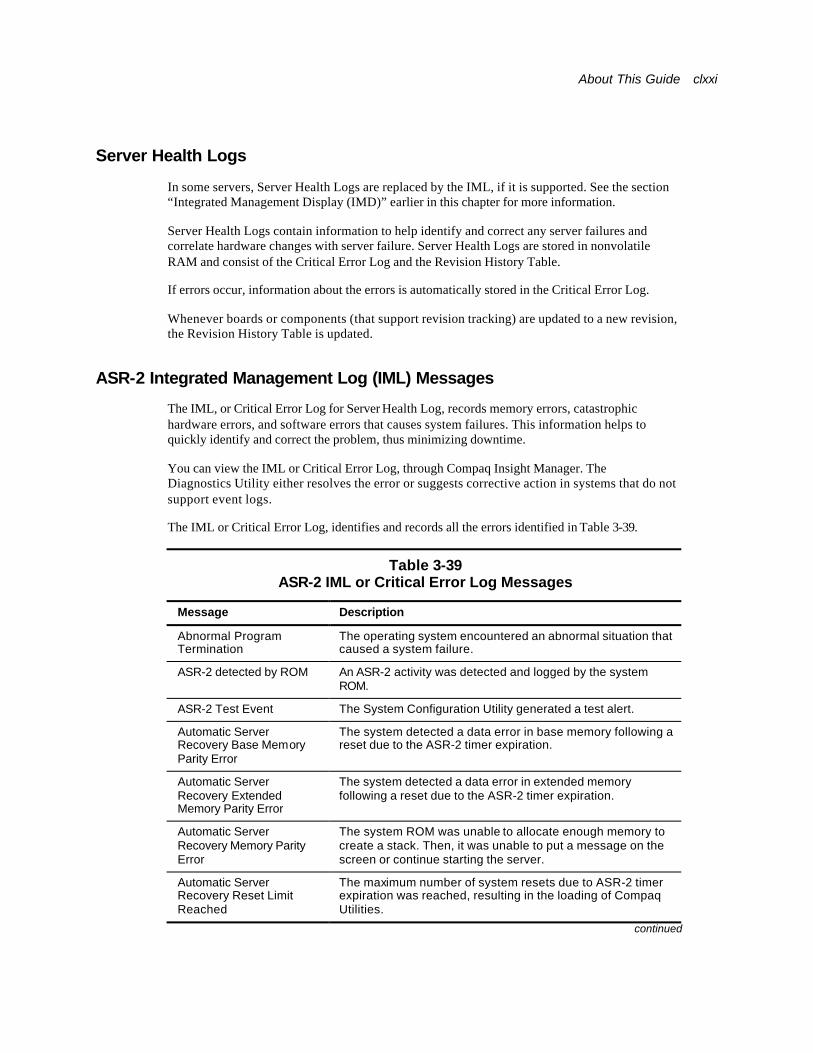
About This Guide clxxi
Server Health Logs
In some servers, Server Health Logs are replaced by the IML, if it is supported. See the section “Integrated Management Display (IMD)” earlier in this chapter for more information.
Server Health Logs contain information to help identify and correct any server failures and correlate hardware changes with server failure. Server Health Logs are stored in nonvolatile RAM and consist of the Critical Error Log and the Revision History Table.
If errors occur, information about the errors is automatically stored in the Critical Error Log.
Whenever boards or components (that support revision tracking) are updated to a new revision, the Revision History Table is updated.
ASR-2 Integrated Management Log (IML) Messages
The IML, or Critical Error Log for Server Health Log, records memory errors, catastrophic hardware errors, and software errors that causes system failures. This information helps to quickly identify and correct the problem, thus minimizing downtime.
You can view the IML or Critical Error Log, through Compaq Insight Manager. The Diagnostics Utility either resolves the error or suggests corrective action in systems that do not support event logs.
The IML or Critical Error Log, identifies and records all the errors identified in Table 3-39.
Table 3-39 ASR-2 IML or Critical Error Log Messages
Message Description
Abnormal Program Termination
The operating system encountered an abnormal situation that caused a system failure.
ASR-2 detected by ROM An ASR-2 activity was detected and logged by the system ROM.
ASR-2 Test Event The System Configuration Utility generated a test alert.
Automatic Server Recovery Base Memory Parity Error
The system detected a data error in base memory following a reset due to the ASR-2 timer expiration.
Automatic Server Recovery Extended Memory Parity Error
The system detected a data error in extended memory following a reset due to the ASR-2 timer expiration.
Automatic Server Recovery Memory Parity Error
The system ROM was unable to allocate enough memory to create a stack. Then, it was unable to put a message on the screen or continue starting the server.
Automatic Server Recovery Reset Limit Reached
The maximum number of system resets due to ASR-2 timer expiration was reached, resulting in the loading of Compaq Utilities.
continued
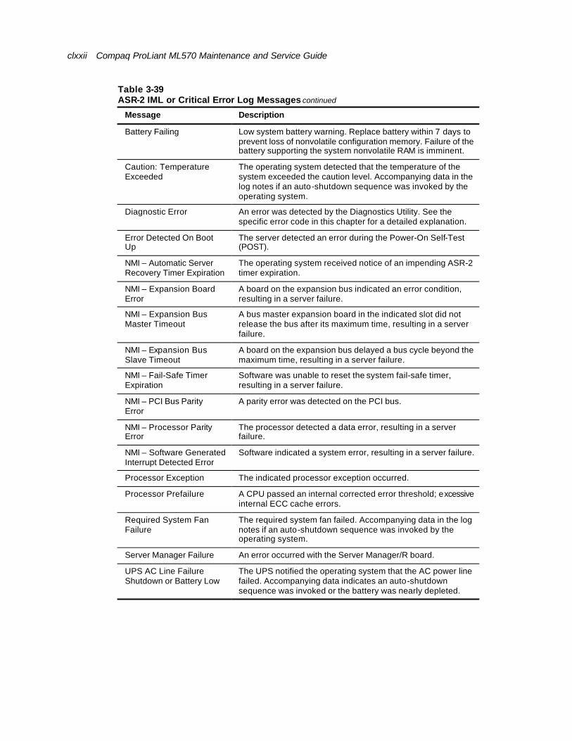
clxxii Compaq ProLiant ML570 Maintenance and Service Guide
Table 3-39 ASR-2 IML or Critical Error Log Messages continued
Message Description
Battery Failing Low system battery warning. Replace battery within 7 days to prevent loss of nonvolatile configuration memory. Failure of the battery supporting the system nonvolatile RAM is imminent.
Caution: Temperature Exceeded
The operating system detected that the temperature of the system exceeded the caution level. Accompanying data in the log notes if an auto-shutdown sequence was invoked by the operating system.
Diagnostic Error An error was detected by the Diagnostics Utility. See the specific error code in this chapter for a detailed explanation.
Error Detected On Boot Up
The server detected an error during the Power-On Self-Test (POST).
NMI – Automatic Server Recovery Timer Expiration
The operating system received notice of an impending ASR-2 timer expiration.
NMI – Expansion Board Error
A board on the expansion bus indicated an error condition, resulting in a server failure.
NMI – Expansion Bus Master Timeout
A bus master expansion board in the indicated slot did not release the bus after its maximum time, resulting in a server failure.
NMI – Expansion Bus Slave Timeout
A board on the expansion bus delayed a bus cycle beyond the maximum time, resulting in a server failure.
NMI – Fail-Safe Timer Expiration
Software was unable to reset the system fail-safe timer, resulting in a server failure.
NMI – PCI Bus Parity Error
A parity error was detected on the PCI bus.
NMI – Processor Parity Error
The processor detected a data error, resulting in a server failure.
NMI – Software Generated Interrupt Detected Error
Software indicated a system error, resulting in a server failure.
Processor Exception The indicated processor exception occurred.
Processor Prefailure A CPU passed an internal corrected error threshold; excessive internal ECC cache errors.
Required System Fan Failure
The required system fan failed. Accompanying data in the log notes if an auto-shutdown sequence was invoked by the operating system.
Server Manager Failure An error occurred with the Server Manager/R board.
UPS AC Line Failure Shutdown or Battery Low
The UPS notified the operating system that the AC power line failed. Accompanying data indicates an auto-shutdown sequence was invoked or the battery was nearly depleted.
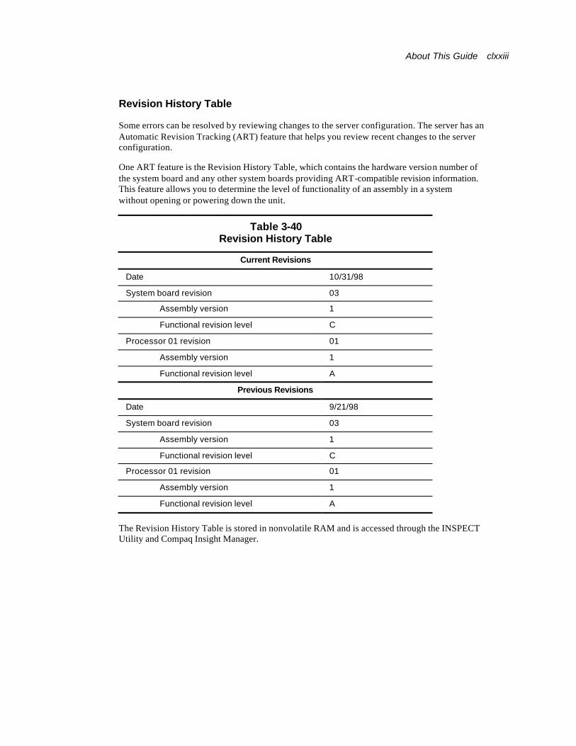
About This Guide clxxiii
Revision History Table
Some errors can be resolved by reviewing changes to the server configuration. The server has an Automatic Revision Tracking (ART) feature that helps you review recent changes to the server configuration.
One ART feature is the Revision History Table, which contains the hardware version number of the system board and any other system boards providing ART-compatible revision information. This feature allows you to determine the level of functionality of an assembly in a system without opening or powering down the unit.
Table 3-40 Revision History Table
Current Revisions
Date 10/31/98
System board revision 03
Assembly version 1
Functional revision level C
Processor 01 revision 01
Assembly version 1
Functional revision level A
Previous Revisions
Date 9/21/98
System board revision 03
Assembly version 1
Functional revision level C
Processor 01 revision 01
Assembly version 1
Functional revision level A
The Revision History Table is stored in nonvolatile RAM and is accessed through the INSPECT Utility and Compaq Insight Manager.
clxxiv Compaq ProLiant ML570 Maintenance and Service Guide
Storage Fault Recovery Tracking
This feature tracks over 12 failure-indication parameters, such as timeouts, spin-up errors, and self-test errors of SCSI drives. You can use these parameters to pinpoint failed storage subsystem components and to recover from controller or hard drive failure.
Storage Automatic Reconstruction
This feature automatically reconstructs data to an online spare or to a replaced drive if a drive fails. To use the reconstruction feature, you must configure the server for drive mirroring or data guarding. The reconstruction decreases system downtime by allowing rapid recovery to full system operation if a drive fails.
Network Interface Fault Recovery Tracking
This feature tracks over 20 failure indication parameters, such as alignment errors, lost frames, and frame copy errors of Ethernet and Token-Ring network interfaces. It decreases network downtime by enabling diagnosis of actual network interface failures.
Memory Fault Recovery Tracking
This feature inspects the operation of the memory subsystem looking for uncorrectable memory errors.
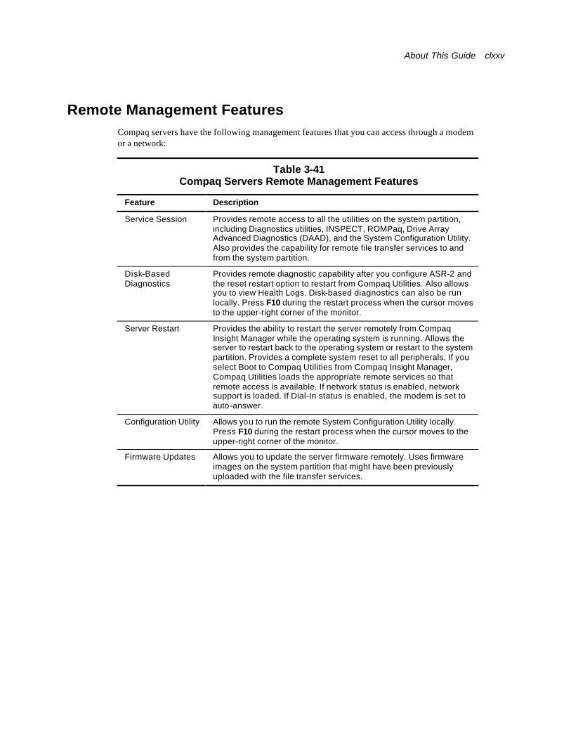
About This Guide clxxv
Remote Management Features Compaq servers have the following management features that you can access through a modem or a network:
Table 3-41 Compaq Servers Remote Management Features
Feature Description
Service Session Provides remote access to all the utilities on the system partition, including Diagnostics utilities, INSPECT, ROMPaq, Drive Array Advanced Diagnostics (DAAD), and the System Configuration Utility. Also provides the capability for remote file transfer services to and from the system partition.
Disk-Based Diagnostics
Provides remote diagnostic capability after you configure ASR-2 and the reset restart option to restart from Compaq Utilities. Also allows you to view Health Logs. Disk-based diagnostics can also be run locally. Press F10 during the restart process when the cursor moves to the upper-right corner of the monitor.
Server Restart Provides the ability to restart the server remotely from Compaq Insight Manager while the operating system is running. Allows the server to restart back to the operating system or restart to the system partition. Provides a complete system reset to all peripherals. If you select Boot to Compaq Utilities from Compaq Insight Manager, Compaq Utilities loads the appropriate remote services so that remote access is available. If network status is enabled, network support is loaded. If Dial-In status is enabled, the modem is set to auto-answer.
Configuration Utility Allows you to run the remote System Configuration Utility locally. Press F10 during the restart process when the cursor moves to the upper-right corner of the monitor.
Firmware Updates Allows you to update the server firmware remotely. Uses firmware images on the system partition that might have been previously uploaded with the file transfer services.
clxxvi Compaq ProLiant ML570 Maintenance and Service Guide
ROMPaq Error Recovery Options From time to time it may be desirable to upgrade the current system ROM. Some reasons for this may be as follows:
n Customer desires ROM upgrade
n Obtained new SmartStart CD-ROM
n Desire to upgrade server processors
n Request from Compaq
The process of upgrading the system ROM is referred to as flashing the ROM. Flashing consists of using software to replace the current ROM image with a new one through ROMPaq.
Should an error such as a power failure occur during this process, the flash operation is not completed, causing the ROM image in the server to be corrupted. Compaq provides two options for ROMPaq recovery, depending on the server and circumstances involved.
ROMPaq Disaster Recovery
If a server does not have a valid ROM image, perform the following process:
IMPORTANT: This operation should be performed on a server with redundant ROM ONLY IF both ROM images have been corrupted. If only one image is corrupted, read the section following, “Redundant ROM Image Recovery” for complete instructions.
22. Create a new ROMPaq diskette, using the latest version for the server involved.
IMPORTANT: If the ROM is corrupted by a ROMPaq interruption, the initial ROMPaq attempt may have affected the contents of the original diskette.
23. Power down the server.
24. Activate disaster recovery mode by setting the configuration switches on the system maintenance switch block.
IMPORTANT: These switch settings are different for each server. Refer to the switch setting information contained in the user documentation provided for your server to find these settings for your server.
Make a note of the positions of all switches in this switch box, so they may be restored after successful completion of this process.
25. Insert the ROMPaq diskette.
Although you utilize a standard ROMPaq diskette, the old ROM image is not saved during this process.
26. Power up the server.
The keyboard, mouse, and monitor are all inactive. If your server has an IMD, it is active. The server generates two long beeps to indicate you are in Disaster Recovery Mode.
About This Guide clxxvii
27. The server analyzes the diskette, searching for the latest ROM image. If the diskette is not in place, the system continues to beep until a valid ROMPaq diskette is inserted.
NOTE: If your server has an IMD that displays “Please insert ROMPaq diskette” even after a valid ROMPaq diskette has been installed—disregard this message as long as the server stops beeping. No beeps indicate the diskette is a valid ROMPaq diskette.
28. The ROMPaq diskette flashes the system ROM. If your server has an IMD, the IMD displays the following message:
ROMPaq flashing system ROM
29. At the successful completion of this process, a sequence of audible ascending beeps is generated, and the IMD displays:
ROMPaq flash successful - Cycle Power
–Or–
If the flash is not successful, a descending sequence of audible beeps is generated, and the IMD displays:
ROMPaq flash failed
30. After successful completion of this process, follow these steps:
a. Power down the server.
b. Reset configuration switches.
c. Power up the server as usual.
–Or–
After a failed ROMPaq upgrade procedure, power down the server and repeat the above process.
IMPORTANT: If you are performing this procedure on a server with redundant ROM, and both ROM images have been corrupted, repeat the process in succession (once for each corrupted image). If only one image is corrupted, read the following section, “Redundant ROM Image Recovery” for complete instructions.
Redundant ROM Image Recovery
If power is interrupted during the flash process, a server with redundant ROM powers up as usual, but the inactive (redundant) ROM image is corrupted.
A POST error message displays:
105 – Current System ROM is corrupt – now booting redundant System ROM.
In this instance, you are required to flash again so that the invalid image is now valid. After you flash the invalid image, the system boots to that image—which was the original objective.
clxxviii Compaq ProLiant ML570 Maintenance and Service Guide
Compaq Insight Manager Compaq Insight Manager is a comprehensive management tool to monitor and control the operation of Compaq servers and clients. Compaq Insight Manager consists of two components: a Windows-based console application, and server- or client-based management data collection agents. Starting with Compaq Insight Manager 4.0, the agents for Windows NT and NetWare are also Web-enabled; that is, these agents enable Web browser access and monitoring of management information.
The management agents monitor more than 1,000 management parameters. Key subsystems are instrumented to make health, configuration, and performance data available to the agent software. The agents act upon that data by initiating information such as network interface or storage subsystem performance statistics.
Features of Compaq Insight Manager
Compaq Insight Manager includes the following:
n Web browser access to Insight Manager Device and Configuration information is available anywhere you have network access and a standard Web browser for Windows and NetWare servers.
n Comprehensive fault management allows proactive management of the distributed enterprise by alerting you in advance of potential system failures.
n Windows NT monitoring capability allows faster determination of the root cause of system and application faults by being able to quickly determine whether hardware or software causes an event.
n Broad configuration management provides effective deployment and maintenance of consistent, manageable configurations with Insight Version Control and Integration Server Maintenance. Version Control and Integration Server Maintenance allows the administrator to monitor and update versions of the server and workstation firmware, drivers, and utilities.
n Performance management/resource utilization helps determine how servers are utilized, and if upgrades or updates are necessary to increase overall system performance.
n Full integration with Compaq Remote Insight Board/PCI and ProLiant Integrated Remote Console allows “in-band” and “out-of-band” connection for server management. This capability ensures that customers are in touch with their systems, even when servers are offline or without power.
n Simple Network Management Protocol (SNMP) standards provide integration with other management products.
n Flexible network conductivity supports multiple transport protocols including IPX, TCP/IP, and PPP to operate over LANs, WANs, and modems.
n Support for the following leading operating systems:
q Microsoft Windows NT
q Novell NetWare, IntranetWare, and IntranetWare for Small Business
q SCO UNIX, OpenServer, and UnixWare
About This Guide clxxix
q IBM OS/2 Warp family of products
n In Compaq servers, every hardware subsystem (such as disk storage, system memory, and system processor) has a robust set of management capabilities. Compaq Full-Spectrum Fault Management prevents faults before they happen, keeps the system up and running in the unlikely event of a failure, and delivers rapid server recovery to normal operation after a fault.
Compaq Insight Manager Software Architecture
The Compaq Insight Manager software architecture is typical of other network management solutions. It has a client/server architecture and is composed of agent software (Compaq Insight Management Agents) and the management application software (Compaq Insight Manager).
Insight Management Agents
Insight Management Agents operate on Compaq systems (such as servers and workstations), performing in-depth monitoring of the state of the system by collecting and measuring system parameters. These parameters indicate the current state of subsystems by counting the occurrence of particular events (for example, the number of read operations performed on a disk drive) or monitoring the state of a critical function (such as whether the cooling fan is operating).
Insight Desktop Agents operate on Compaq Deskpro™ computers, monitoring functions that include temperature sensing and disk prefailure alerting.
Insight Agents provide information to management applications, such as Compaq Insight Management, and can generate alarm notifications if significant changes occur in the fault or performance aspects of system operation. Information is delivered to and from the Insight Agents by the industry-standard SNMP.
Compaq Insight Manager
Compaq Insight Manager delivers intelligent monitoring and alerting as well as visual control of the Compaq hardware. In the unlikely event of hardware failures, Compaq Insight Manager also provides a full complement of remote maintenance and control facilities.
For additional information, refer to the online Compaq Insight Manager User Guide on the server documentation CD that accompanied the server.
Chapter 4
Connectors, Switches, and LED Status Indicators
This chapter provides connector, switch, and LED status indicator information for the Compaq ProLiant ML570 server.
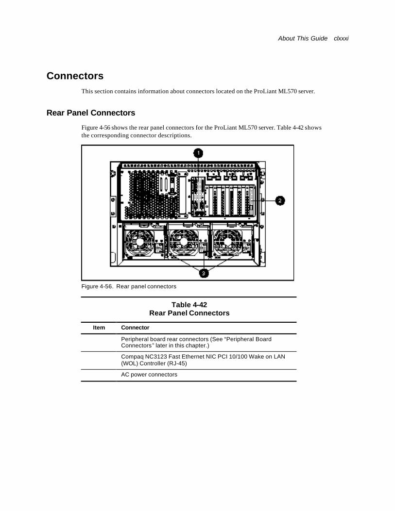
About This Guide clxxxi
Connectors This section contains information about connectors located on the ProLiant ML570 server.
Rear Panel Connectors
Figure 4-56 shows the rear panel connectors for the ProLiant ML570 server. Table 4-42 shows the corresponding connector descriptions.
Figure 4-56. Rear panel connectors
Table 4-42 Rear Panel Connectors
Item Connector
⊇ Peripheral board rear connectors (See “Peripheral Board Connectors” later in this chapter.)
⊄ Compaq NC3123 Fast Ethernet NIC PCI 10/100 Wake on LAN (WOL) Controller (RJ-45)
⊂ AC power connectors
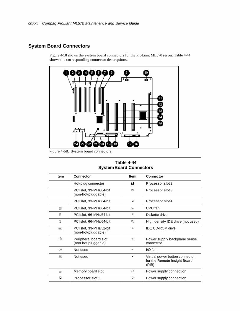
clxxxii Compaq ProLiant ML570 Maintenance and Service Guide
System Board Connectors
Figure 4-58 shows the system board connectors for the ProLiant ML570 server. Table 4-44 shows the corresponding connector descriptions.
Figure 4-58. System board connectors
Table 4-44 System Board Connectors
Item Connector Item Connector
⊇ Hot-plug connector = Processor slot 2
⊄ PCI slot, 33-MHz/64-bit (non-hot-pluggable)
> Processor slot 3
⊂ PCI slot, 33-MHz/64-bit ? Processor slot 4
4 PCI slot, 33-MHz/64-bit @ CPU fan
5 PCI slot, 66-MHz/64-bit A Diskette drive
6 PCI slot, 66-MHz/64-bit B High density IDE drive (not used)
7 PCI slot, 33-MHz/32-bit (non-hot-pluggable)
C IDE CD-ROM drive
8 Peripheral board slot (non-hot-pluggable)
D Power supply backplane sense connector
9 Not used E I/O fan
: Not used s Virtual power button connector for the Remote Insight Board (RIB)
; Memory board slot d Power supply connection
< Processor slot 1 f Power supply connection
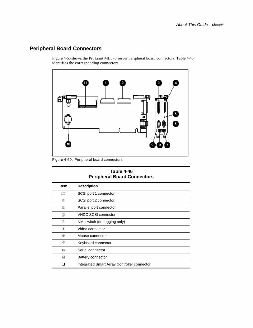
About This Guide clxxxiii
Peripheral Board Connectors
Figure 4-60 shows the ProLiant ML570 server peripheral board connectors. Table 4-46 identifies the corresponding connectors.
Figure 4-60. Peripheral board connectors
Table 4-46 Peripheral Board Connectors
Item Description
1 SCSI port 1 connector
2 SCSI port 2 connector
3 Parallel port connector
4 VHDC SCSI connector
5 NMI switch (debugging only)
6 Video connector
7 Mouse connector
8 Keyboard connector
9 Serial connector
: Battery connector
q Integrated Smart Array Controller connector
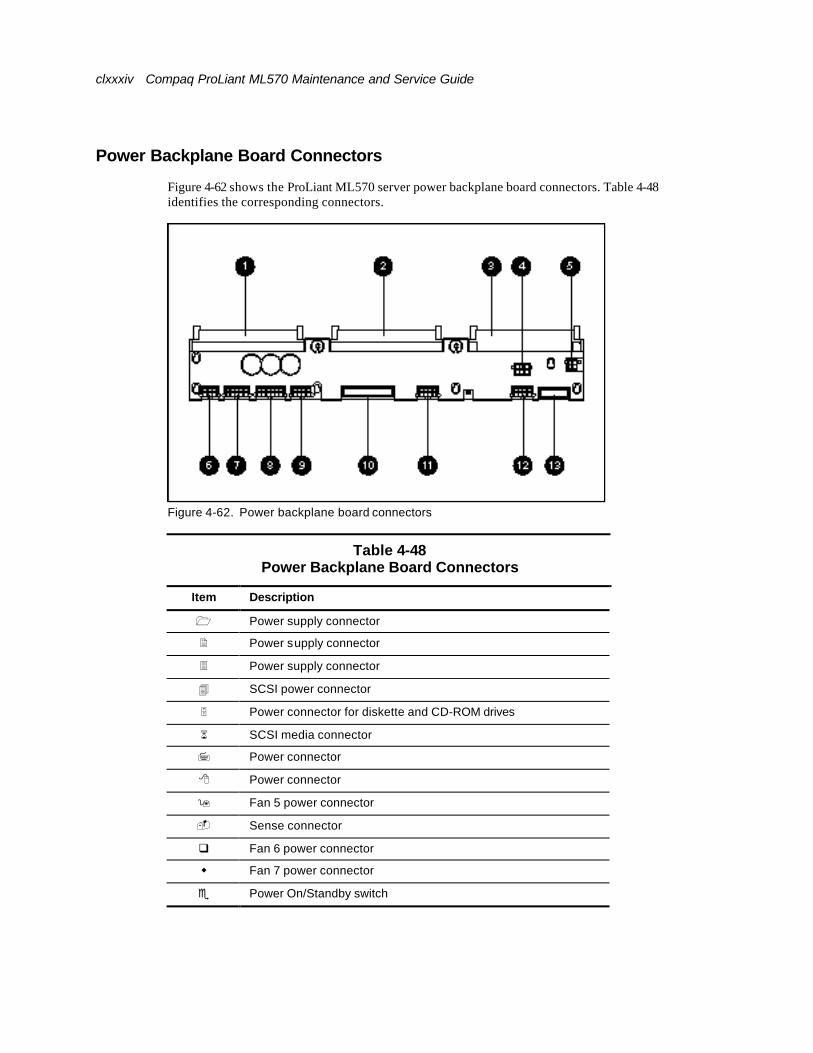
clxxxiv Compaq ProLiant ML570 Maintenance and Service Guide
Power Backplane Board Connectors
Figure 4-62 shows the ProLiant ML570 server power backplane board connectors. Table 4-48 identifies the corresponding connectors.
Figure 4-62. Power backplane board connectors
Table 4-48 Power Backplane Board Connectors
Item Description
1 Power supply connector
2 Power supply connector
3 Power supply connector
4 SCSI power connector
5 Power connector for diskette and CD-ROM drives
6 SCSI media connector
7 Power connector
8 Power connector
9 Fan 5 power connector
- Sense connector
q Fan 6 power connector
w Fan 7 power connector
e Power On/Standby switch
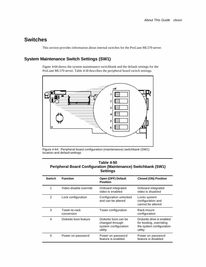
About This Guide clxxxv
Switches This section provides information about internal switches for the ProLiant ML570 server.
System Maintenance Switch Settings (SW1)
Figure 4-64 shows the system maintenance switchbank and the default settings for the ProLiant ML570 server. Table 4-50 describes the peripheral board switch settings.
Figure 4-64. Peripheral board configuration (maintenance) switchbank (SW1) location and default settings
Table 4-50 Peripheral Board Configuration (Maintenance) Switchbank (SW1)
Settings
Switch Function Open (OFF) Default Position
Closed (ON) Position
1 Video disable override Onboard integrated video is enabled
Onboard integrated video is disabled
2 Lock configuration Configuration unlocked and can be altered
Locks system configuration and cannot be altered
3 Tower-to-rack conversion
Tower configuration Rack-mount configuration
4 Diskette boot feature Diskette boot can be changed through system configuration utility
Diskette drive is enabled for booting, overriding the system configuration utility
5 Power on password Power on password feature is enabled
Power on password feature is disabled

clxxxvi Compaq ProLiant ML570 Maintenance and Service Guide
6 Maintenance NVRAM is validated; configuration saved
NVRAM is invalidated; configuration erased

About This Guide clxxxvii
Clearing CMOS
To erase an invalid system configuration:
31. Move the S6 configuration switch (SW1) to the On position. This setting clears portions of CMOS and NVRAM.
32. Power up the server. Wait for the ProLiant logo to display on the video display.
33. Power down the server.
34. Move the S6 configuration switch to the Off position.
35. Power up the server. See Compaq ProLiant ML570 Server Troubleshooting Guide for more information.
To clear all contents of CMOS NVRAM, remove the battery, then reinstall the battery. All device settings have to be completely reconfigured. See Figure 4-64 for the configuration switchbank location and Table 4-50 for the configuration settings.
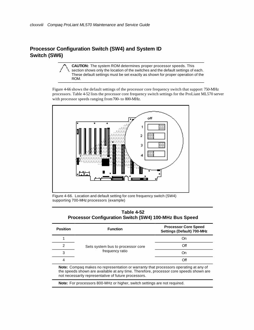
clxxxviii Compaq ProLiant ML570 Maintenance and Service Guide
Processor Configuration Switch (SW4) and System ID Switch (SW6)
CAUTION: The system ROM determines proper processor speeds. This section shows only the location of the switches and the default settings of each. These default settings must be set exactly as shown for proper operation of the ROM.
Figure 4-66 shows the default settings of the processor core frequency switch that support 750-MHz processors. Table 4-52 lists the processor core frequency switch settings for the ProLiant ML570 server with processor speeds ranging from 700- to 800-MHz.
Figure 4-66. Location and default setting for core frequency switch (SW4) supporting 700-MHz processors (example)
Table 4-52 Processor Configuration Switch (SW4) 100-MHz Bus Speed
Position Function Processor Core Speed Settings (Default) 700-MHz
1 On
2 Off
3 On
4
Sets system bus to processor core frequency ratio
Off
Note: Compaq makes no representation or warranty that processors operating at any of the speeds shown are available at any time. Therefore, processor core speeds shown are not necessarily representative of future processors.
Note: For processors 800-MHz or higher, switch settings are not required.
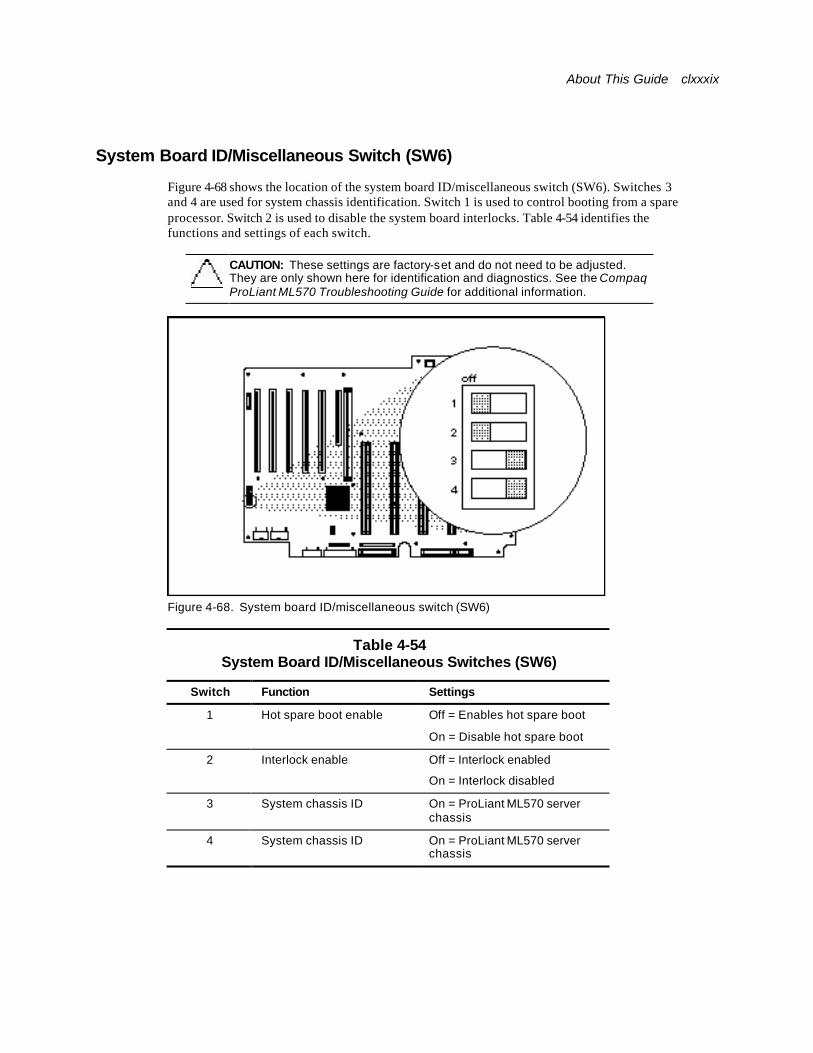
About This Guide clxxxix
System Board ID/Miscellaneous Switch (SW6)
Figure 4-68 shows the location of the system board ID/miscellaneous switch (SW6). Switches 3 and 4 are used for system chassis identification. Switch 1 is used to control booting from a spare processor. Switch 2 is used to disable the system board interlocks. Table 4-54 identifies the functions and settings of each switch.
CAUTION: These settings are factory-set and do not need to be adjusted. They are only shown here for identification and diagnostics. See the Compaq ProLiant ML570 Troubleshooting Guide for additional information.
Figure 4-68. System board ID/miscellaneous switch (SW6)
Table 4-54 System Board ID/Miscellaneous Switches (SW6)
Switch Function Settings
1 Hot spare boot enable Off = Enables hot spare boot
On = Disable hot spare boot
2 Interlock enable Off = Interlock enabled
On = Interlock disabled
3 System chassis ID On = ProLiant ML570 server chassis
4 System chassis ID On = ProLiant ML570 server chassis
cxc Compaq ProLiant ML570 Maintenance and Service Guide
LED Status Indicators This section contains information on service LED indicators located on the ProLiant ML570 server. LED indicators covered in this section include:
n Power Switch and Front Panel LED Indicators
n Hot-Plug Fan LED Indicators
n Interlock Status LED Indicators
n Internal Diagnostics Display (IDD)
n PCI Hot Plug Switchboard LED Indicators
n RJ-45 Network Connector Status LED Indicators
n Hot-Plug Power Supply Diagnostic LED Indicators
n CD-ROM Drive LED Indicator
n Diskette Drive LED Indicator
n Hot-Plug Hard Drive LED Indicators
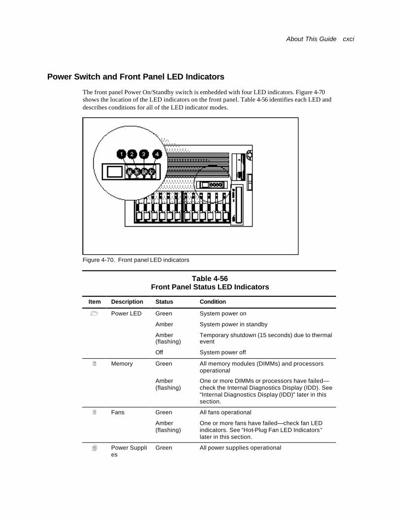
About This Guide cxci
Power Switch and Front Panel LED Indicators
The front panel Power On/Standby switch is embedded with four LED indicators. Figure 4-70 shows the location of the LED indicators on the front panel. Table 4-56 identifies each LED and describes conditions for all of the LED indicator modes.
Figure 4-70. Front panel LED indicators
Table 4-56 Front Panel Status LED Indicators
Item Description Status Condition
1 Power LED Green System power on
Amber System power in standby
Amber (flashing)
Temporary shutdown (15 seconds) due to thermal event
Off System power off
2 Memory Green All memory modules (DIMMs) and processors operational
Amber (flashing)
One or more DIMMs or processors have failed—check the Internal Diagnostics Display (IDD). See “Internal Diagnostics Display (IDD)” later in this section.
3 Fans Green All fans operational
Amber (flashing)
One or more fans have failed—check fan LED indicators. See “Hot-Plug Fan LED Indicators” later in this section.
4 Power Supplies
Green All power supplies operational

cxcii Compaq ProLiant ML570 Maintenance and Service Guide
Amber (flashing)
One or more power supplies have failed—check power supply LED indicators. See Table 4-63 “Hot-Plug Power Supply Diagnostic LED Indicators” later in this section.
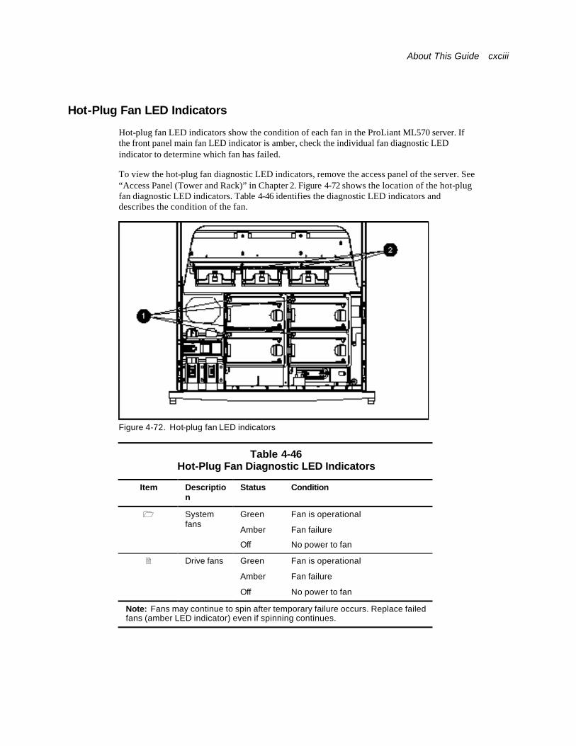
About This Guide cxciii
Hot-Plug Fan LED Indicators
Hot-plug fan LED indicators show the condition of each fan in the ProLiant ML570 server. If the front panel main fan LED indicator is amber, check the individual fan diagnostic LED indicator to determine which fan has failed.
To view the hot-plug fan diagnostic LED indicators, remove the access panel of the server. See “Access Panel (Tower and Rack)” in Chapter 2. Figure 4-72 shows the location of the hot-plug fan diagnostic LED indicators. Table 4-46 identifies the diagnostic LED indicators and describes the condition of the fan.
Figure 4-72. Hot-plug fan LED indicators
Table 4-46 Hot-Plug Fan Diagnostic LED Indicators
Item Description
Status Condition
1 System fans
Green
Amber
Off
Fan is operational
Fan failure
No power to fan
2 Drive fans Green
Amber
Off
Fan is operational
Fan failure
No power to fan
Note: Fans may continue to spin after temporary failure occurs. Replace failed fans (amber LED indicator) even if spinning continues.
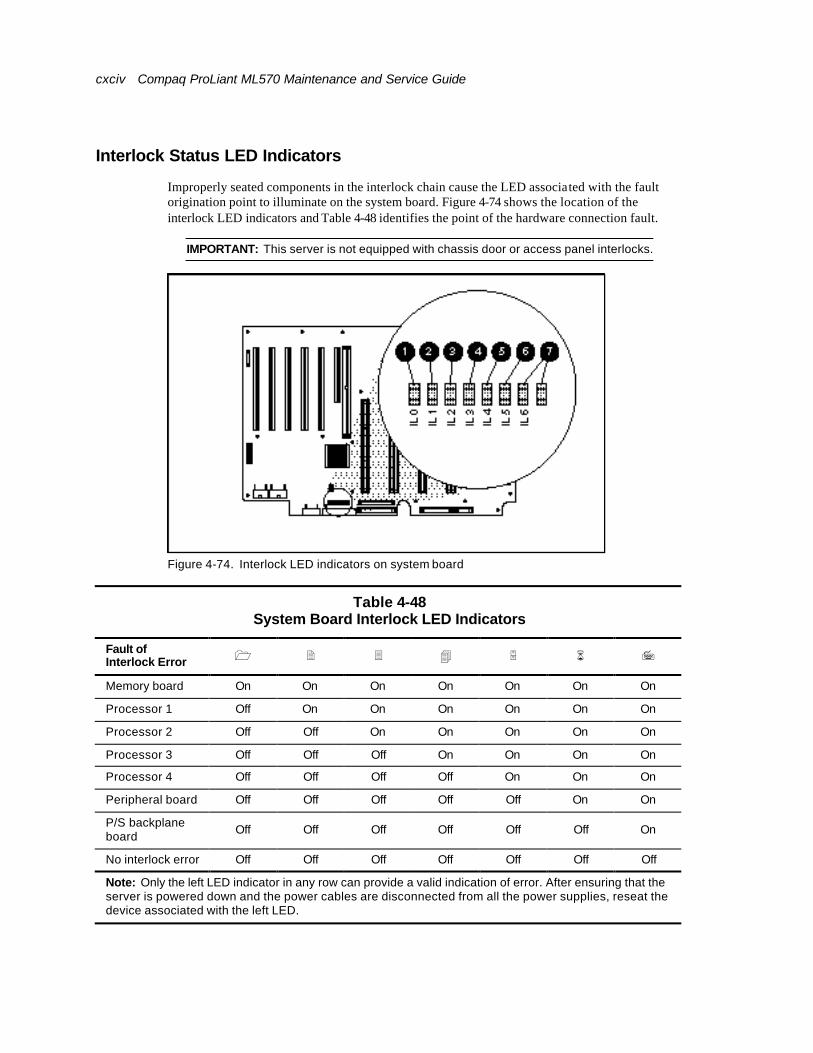
cxciv Compaq ProLiant ML570 Maintenance and Service Guide
Interlock Status LED Indicators
Improperly seated components in the interlock chain cause the LED associated with the fault origination point to illuminate on the system board. Figure 4-74 shows the location of the interlock LED indicators and Table 4-48 identifies the point of the hardware connection fault.
IMPORTANT: This server is not equipped with chassis door or access panel interlocks.
Figure 4-74. Interlock LED indicators on system board
Table 4-48 System Board Interlock LED Indicators
Fault of Interlock Error 1 2 3 4 5 6 7
Memory board On On On On On On On
Processor 1 Off On On On On On On
Processor 2 Off Off On On On On On
Processor 3 Off Off Off On On On On
Processor 4 Off Off Off Off On On On
Peripheral board Off Off Off Off Off On On
P/S backplane board Off Off Off Off Off Off On
No interlock error Off Off Off Off Off Off Off
Note: Only the left LED indicator in any row can provide a valid indication of error. After ensuring that the server is powered down and the power cables are disconnected from all the power supplies, reseat the device associated with the left LED.
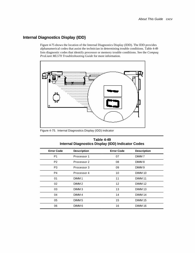
About This Guide cxcv
Internal Diagnostics Display (IDD)
Figure 4-75 shows the location of the Internal Diagnostics Display (IDD). The IDD provides alphanumerical codes that assist the technician in determining trouble conditions. Table 4-49 lists diagnostic codes that identify processor or memory trouble conditions. See the Compaq ProLiant ML570 Troubleshooting Guide for more information.
Figure 4-75. Internal Diagnostics Display (IDD) indicator
Table 4-49 Internal Diagnostics Display (IDD) Indicator Codes
Error Code Description Error Code Description
P1 Processor 1 07 DIMM 7
P2 Processor 2 08 DIMM 8
P3 Processor 3 09 DIMM 9
P4 Processor 4 10 DIMM 10
01 DIMM 1 11 DIMM 11
02 DIMM 2 12 DIMM 12
03 DIMM 3 13 DIMM 13
04 DIMM 4 14 DIMM 14
05 DIMM 5 15 DIMM 15
06 DIMM 6 16 DIMM 16

cxcvi Compaq ProLiant ML570 Maintenance and Service Guide
PCI Hot Plug Switchboard LED Indicators
LED indicators on the PCI Hot Plug switchboard provide information about the condition of the expansion board. Figure 4-76 shows the PCI Hot Plug button LED indicators. Table 4-50 identifies the location of the hot-plug power supply LED indicators and the corresponding LED indicator status descriptions.
Figure 4-76. PCI Hot Plug button LED indicators (1 and 2), and button (3) under the PCI Hot Plug access door
The PCI Hot Plug switchboard LED indicators at each expansion slot provide a visual status of each board slot. The LED indicators are viewed from the rear of the server or by opening the PCI Hot Plug access door on the top access panel.
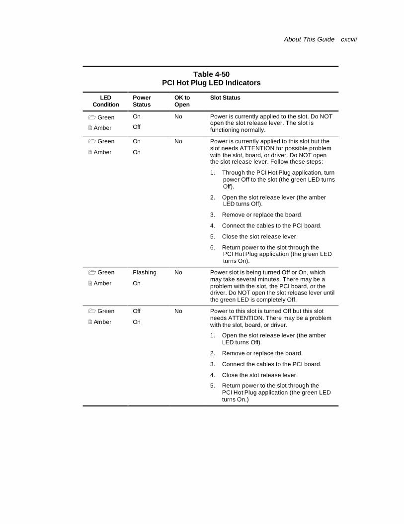
About This Guide cxcvii
Table 4-50 PCI Hot Plug LED Indicators
LED Condition
Power Status
OK to Open
Slot Status
1 Green
2 Amber
On
Off
No Power is currently applied to the slot. Do NOT open the slot release lever. The slot is functioning normally.
1 Green
2 Amber
On
On
No Power is currently applied to this slot but the slot needs ATTENTION for possible problem with the slot, board, or driver. Do NOT open the slot release lever. Follow these steps:
1. Through the PCI Hot Plug application, turn power Off to the slot (the green LED turns Off).
2. Open the slot release lever (the amber LED turns Off).
3. Remove or replace the board.
4. Connect the cables to the PCI board.
5. Close the slot release lever.
6. Return power to the slot through the PCI Hot Plug application (the green LED turns On).
1 Green
2 Amber
Flashing
On
No Power slot is being turned Off or On, which may take several minutes. There may be a problem with the slot, the PCI board, or the driver. Do NOT open the slot release lever until the green LED is completely Off.
1 Green
2 Amber
Off
On
No Power to this slot is turned Off but this slot needs ATTENTION. There may be a problem with the slot, board, or driver.
1. Open the slot release lever (the amber LED turns Off).
2. Remove or replace the board.
3. Connect the cables to the PCI board.
4. Close the slot release lever.
5. Return power to the slot through the PCI Hot Plug application (the green LED turns On.)
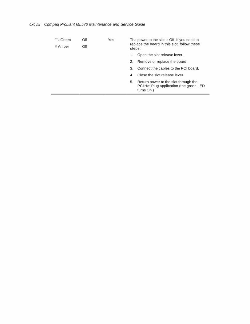
cxcviii Compaq ProLiant ML570 Maintenance and Service Guide
1 Green
2 Amber
Off
Off
Yes The power to the slot is Off. If you need to replace the board in this slot, follow these steps:
1. Open the slot release lever.
2. Remove or replace the board.
3. Connect the cables to the PCI board.
4. Close the slot release lever.
5. Return power to the slot through the PCI Hot Plug application (the green LED turns On.)
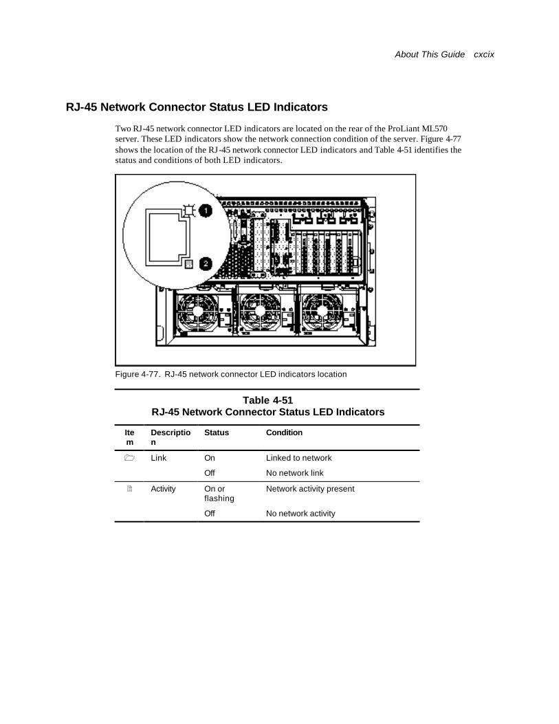
About This Guide cxcix
RJ-45 Network Connector Status LED Indicators
Two RJ-45 network connector LED indicators are located on the rear of the ProLiant ML570 server. These LED indicators show the network connection condition of the server. Figure 4-77 shows the location of the RJ-45 network connector LED indicators and Table 4-51 identifies the status and conditions of both LED indicators.
Figure 4-77. RJ-45 network connector LED indicators location
Table 4-51 RJ-45 Network Connector Status LED Indicators
Item
Description
Status Condition
1 Link On Linked to network
Off No network link
2 Activity On or flashing
Network activity present
Off No network activity
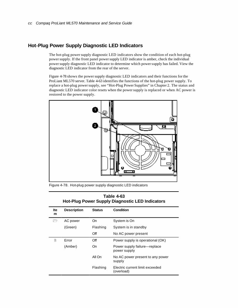
cc Compaq ProLiant ML570 Maintenance and Service Guide
Hot-Plug Power Supply Diagnostic LED Indicators
The hot-plug power supply diagnostic LED indicators show the condition of each hot-plug power supply. If the front panel power supply LED indicator is amber, check the individual power supply diagnostic LED indicator to determine which power supply has failed. View the diagnostic LED indicator from the rear of the server.
Figure 4-78 shows the power supply diagnostic LED indicators and their functions for the ProLiant ML570 server. Table 4-63 identifies the functions of the hot-plug power supply. To replace a hot-plug power supply, see “Hot-Plug Power Supplies” in Chapter 2. The status and diagnostic LED indicator color resets when the power supply is replaced or when AC power is restored to the power supply.
Figure 4-78. Hot-plug power supply diagnostic LED indicators
Table 4-63 Hot-Plug Power Supply Diagnostic LED Indicators
Item
Description Status Condition
1 AC power On System is On
(Green) Flashing System is in standby
Off No AC power present
2 Error Off Power supply is operational (OK)
(Amber) On Power supply failure—replace power supply
All On No AC power present to any power supply
Flashing Electric current limit exceeded (overload)

About This Guide cci
CD-ROM Drive LED Indicator
The CD-ROM drive LED indicator 1 is located on the front of the CD-ROM drive near the volume wheel. The LED indicator illuminates green whenever the CD-ROM drive is in operation. Figure 4-79 shows the CD-ROM drive LED indicator for the ProLiant ML570 server.
Figure 4-79. CD-ROM drive LED indicator
Diskette Drive LED Indicator
Figure 4-80 shows the location of the diskette drive LED indicator 1. The LED indicator illuminates green when the diskette drive is in operation. Figure 4-80 shows the diskette drive LED indicator on the ProLiant ML570 server.
Figure 4-80. Diskette drive LED indicator

ccii Compaq ProLiant ML570 Maintenance and Service Guide
Hot-Plug Hard Drive LED Indicators
Each hot-plug hard drive has LED indicators that show the operational status of the hard drive. Figure 4-81 and Table 4-53 show the location, function, and replacement condition for each hot-plug hard drive LED indicator for the ProLiant ML570 server.
CAUTION: Replace a hard drive only when the hard drive LED indicator is amber. Do not remove a hot-plug drive if the online LED indicator is green.
Figure 4-81. Hot-plug hard drive LED indicators
Table 4-53 Hot-Plug SCSI Hard Drive LED Indicators
Drive Activity LED 1
Drive Online LED 2
Drive Fault LED 3
Condition
Off Off Off The drive is off. OK to remove drive.
Off Off Amber Failed drive. Replace hot-plug SCSI hard drive.
Off Green Off Drive is online and configured as part of an array. OK to replace the drive if a predictive failure alert is received.
Green Green Off Drive is online and being accessed. OK to replace the drive if a predictive failure alert is received.
Green Off Off Drive is being accessed. DO NOT remove drive.
Green Flashing green Off Drive is being rebuilt. DO NOT remove drive.

About This Guide cciii
Flashing green Flashing green Flashing amber Drive is being identified by the Array Configuration Utility. DO NOT remove drive.

Chapter 5
Physical and Operating Specifications
This chapter provides specifications for the Compaq ProLiant ML570 server. It includes the following information:
n System Unit
n Hot-Plug Power Supply
n SDRAM Dual Inline Memory Modules
n 1.44-MB Diskette Drive
n IDE CD-ROM Drive
n NC3123 Fast Ethernet NIC PCI 10/100 Wake on LAN (WOL)
n Integrated Dual-Channel Wide Ultra2 SCSI Controller
n Hot-Plug Hard Drives
n Smart Array 4200 Controller
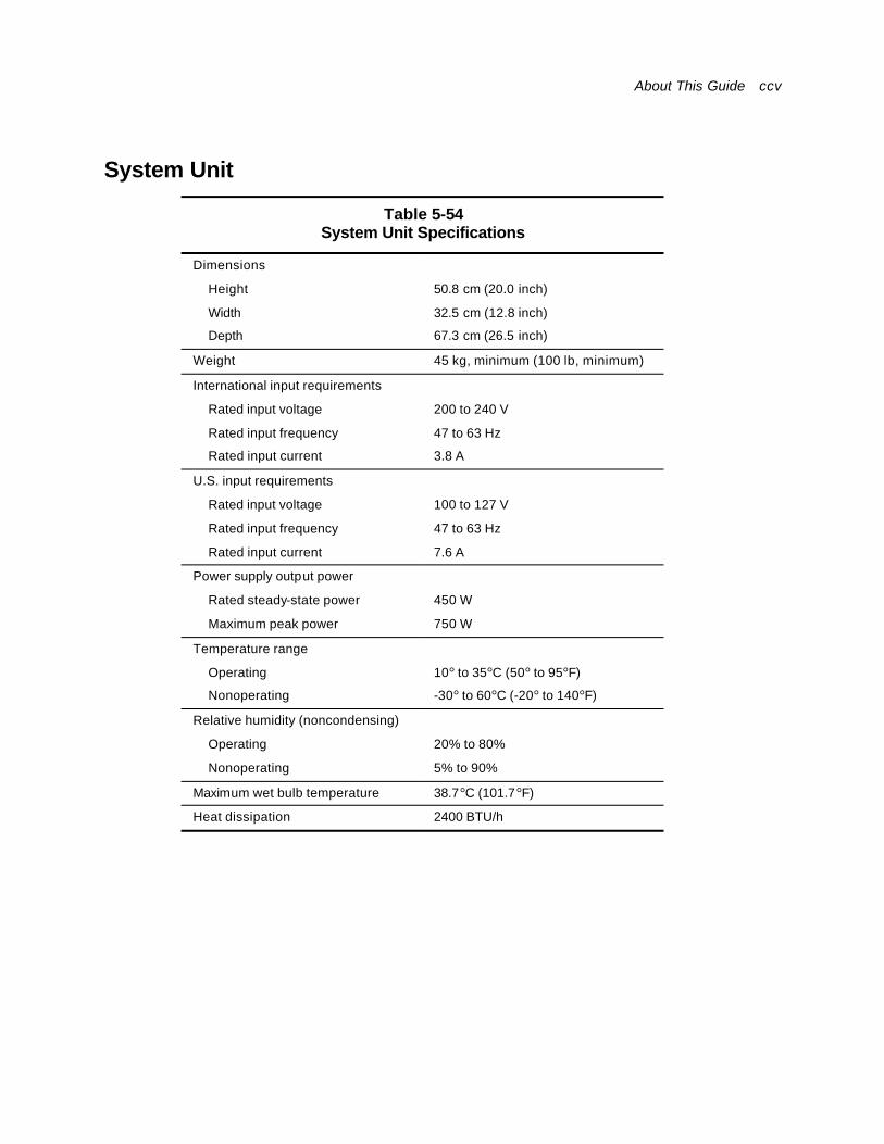
About This Guide ccv
System Unit
Table 5-54 System Unit Specifications
Dimensions
Height 50.8 cm (20.0 inch)
Width 32.5 cm (12.8 inch)
Depth 67.3 cm (26.5 inch)
Weight 45 kg, minimum (100 lb, minimum)
International input requirements
Rated input voltage 200 to 240 V
Rated input frequency 47 to 63 Hz
Rated input current 3.8 A
U.S. input requirements
Rated input voltage 100 to 127 V
Rated input frequency 47 to 63 Hz
Rated input current 7.6 A
Power supply output power
Rated steady-state power 450 W
Maximum peak power 750 W
Temperature range
Operating 10° to 35°C (50° to 95°F)
Nonoperating -30° to 60°C (-20° to 140°F)
Relative humidity (noncondensing)
Operating 20% to 80%
Nonoperating 5% to 90%
Maximum wet bulb temperature 38.7°C (101.7°F)
Heat dissipation 2400 BTU/h
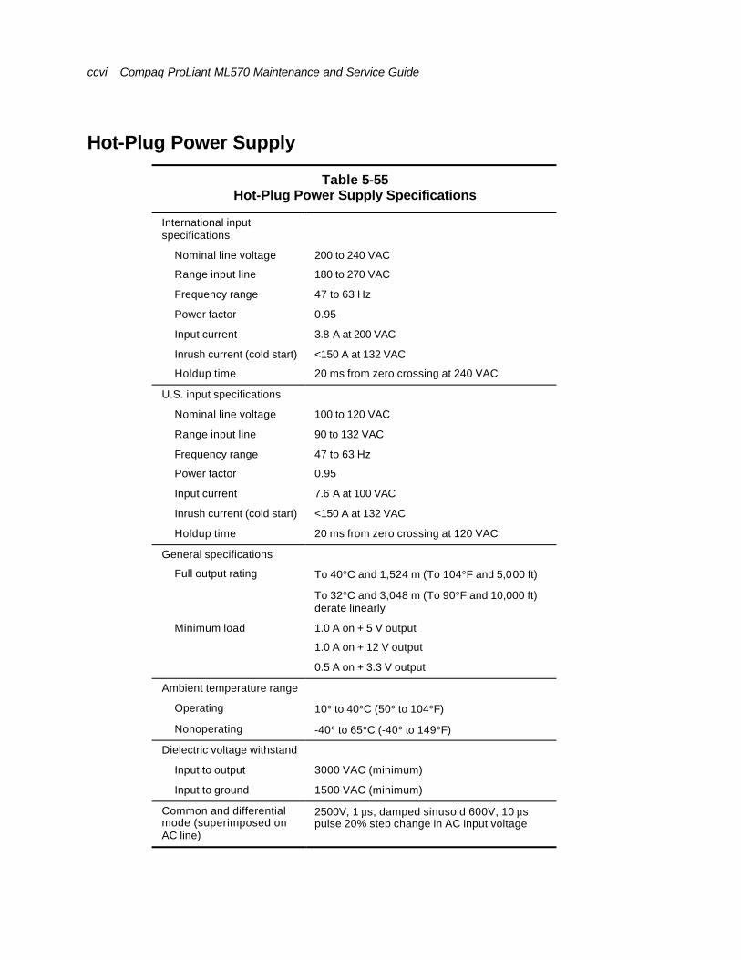
ccvi Compaq ProLiant ML570 Maintenance and Service Guide
Hot-Plug Power Supply
Table 5-55 Hot-Plug Power Supply Specifications
International input specifications
Nominal line voltage 200 to 240 VAC
Range input line 180 to 270 VAC
Frequency range 47 to 63 Hz
Power factor 0.95
Input current 3.8 A at 200 VAC
Inrush current (cold start) <150 A at 132 VAC
Holdup time 20 ms from zero crossing at 240 VAC
U.S. input specifications
Nominal line voltage 100 to 120 VAC
Range input line 90 to 132 VAC
Frequency range 47 to 63 Hz
Power factor 0.95
Input current 7.6 A at 100 VAC
Inrush current (cold start) <150 A at 132 VAC
Holdup time 20 ms from zero crossing at 120 VAC
General specifications
Full output rating To 40°C and 1,524 m (To 104°F and 5,000 ft)
To 32°C and 3,048 m (To 90°F and 10,000 ft) derate linearly
Minimum load 1.0 A on + 5 V output
1.0 A on + 12 V output
0.5 A on + 3.3 V output
Ambient temperature range
Operating 10° to 40°C (50° to 104°F)
Nonoperating -40° to 65°C (-40° to 149°F)
Dielectric voltage withstand
Input to output 3000 VAC (minimum)
Input to ground 1500 VAC (minimum)
Common and differential mode (superimposed on AC line)
2500V, 1 µs, damped sinusoid 600V, 10 µs pulse 20% step change in AC input voltage
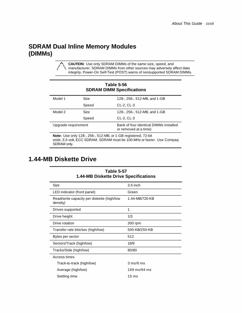
About This Guide ccvii
SDRAM Dual Inline Memory Modules (DIMMs)
CAUTION: Use only SDRAM DIMMs of the same size, speed, and manufacturer. SDRAM DIMMs from other sources may adversely affect data integrity. Power-On Self-Test (POST) warns of nonsupported SDRAM DIMMs.
Table 5-56 SDRAM DIMM Specifications
Model 1 Size 128-, 256-, 512-MB, and 1-GB
Speed CL-2, CL-3
Model 2 Size 128-, 256-, 512-MB, and 1-GB
Speed CL-2, CL-3
Upgrade requirement Bank of four identical DIMMs installed or removed at a time)
Note: Use only 128-, 256-, 512-MB, or 1-GB registered, 72-bit wide, 3.3-volt, ECC SDRAM. SDRAM must be 100-MHz or faster. Use Compaq SDRAM only.
1.44-MB Diskette Drive
Table 5-57 1.44-MB Diskette Drive Specifications
Size 3.5 inch
LED indicator (front panel) Green
Read/write capacity per diskette (high/low density)
1.44-MB/720-KB
Drives supported 1
Drive height 1/3
Drive rotation 300 rpm
Transfer rate bits/sec (high/low) 500-KB/250-KB
Bytes per sector 512
Sectors/Track (high/low) 18/9
Tracks/Side (high/low) 80/80
Access times
Track-to-track (high/low) 3 ms/6 ms
Average (high/low) 169 ms/94 ms
Settling time 15 ms

ccviii Compaq ProLiant ML570 Maintenance and Service Guide
Latency average 100 ms
Cylinders (high/low) 80/80
Read/write heads 2
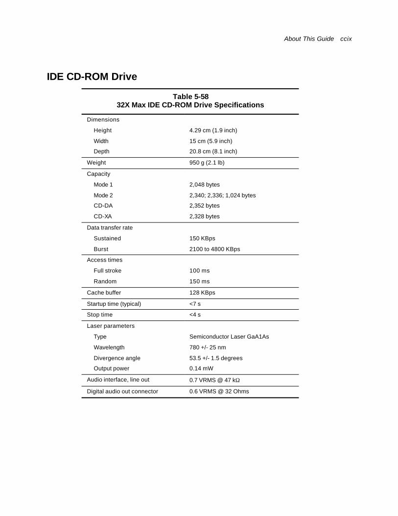
About This Guide ccix
IDE CD-ROM Drive
Table 5-58 32X Max IDE CD-ROM Drive Specifications
Dimensions
Height 4.29 cm (1.9 inch)
Width 15 cm (5.9 inch)
Depth 20.8 cm (8.1 inch)
Weight 950 g (2.1 lb)
Capacity
Mode 1 2,048 bytes
Mode 2 2,340; 2,336; 1,024 bytes
CD-DA 2,352 bytes
CD-XA 2,328 bytes
Data transfer rate
Sustained 150 KBps
Burst 2100 to 4800 KBps
Access times
Full stroke 100 ms
Random 150 ms
Cache buffer 128 KBps
Startup time (typical) <7 s
Stop time <4 s
Laser parameters
Type Semiconductor Laser GaA1As
Wavelength 780 +/- 25 nm
Divergence angle 53.5 +/- 1.5 degrees
Output power 0.14 mW
Audio interface, line out 0.7 VRMS @ 47 kΩ
Digital audio out connector 0.6 VRMS @ 32 Ohms
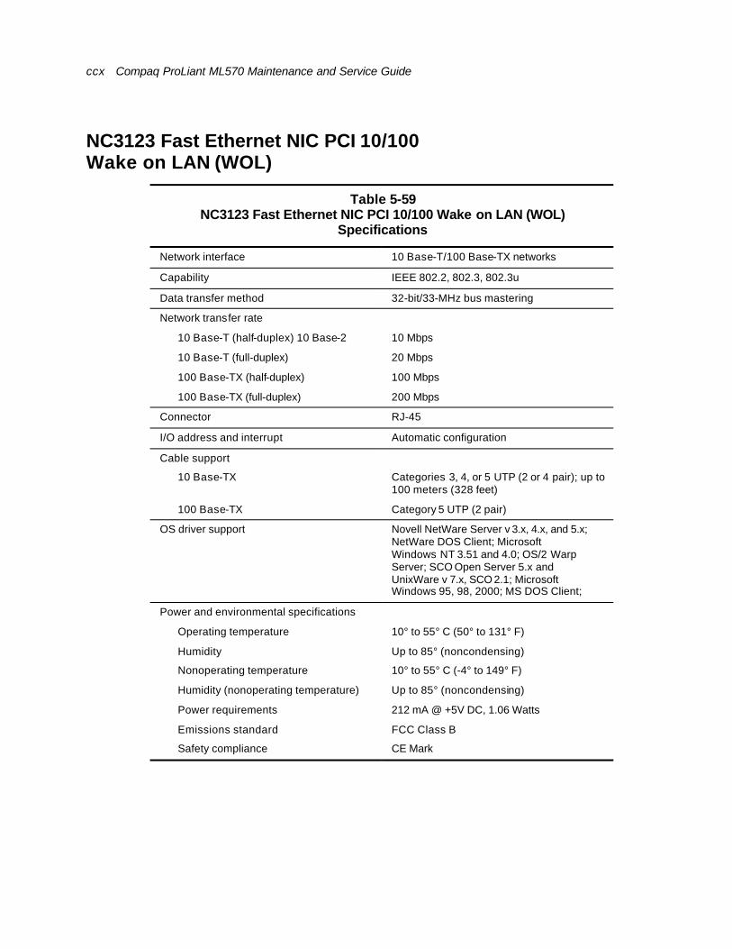
ccx Compaq ProLiant ML570 Maintenance and Service Guide
NC3123 Fast Ethernet NIC PCI 10/100 Wake on LAN (WOL)
Table 5-59 NC3123 Fast Ethernet NIC PCI 10/100 Wake on LAN (WOL)
Specifications
Network interface 10 Base-T/100 Base-TX networks
Capability IEEE 802.2, 802.3, 802.3u
Data transfer method 32-bit/33-MHz bus mastering
Network transfer rate
10 Base-T (half-duplex) 10 Base-2 10 Mbps
10 Base-T (full-duplex) 20 Mbps
100 Base-TX (half-duplex) 100 Mbps
100 Base-TX (full-duplex) 200 Mbps
Connector RJ-45
I/O address and interrupt Automatic configuration
Cable support
10 Base-TX Categories 3, 4, or 5 UTP (2 or 4 pair); up to 100 meters (328 feet)
100 Base-TX Category 5 UTP (2 pair)
OS driver support Novell NetWare Server v 3.x, 4.x, and 5.x; NetWare DOS Client; Microsoft Windows NT 3.51 and 4.0; OS/2 Warp Server; SCO Open Server 5.x and UnixWare v 7.x, SCO 2.1; Microsoft Windows 95, 98, 2000; MS DOS Client;
Power and environmental specifications
Operating temperature 10° to 55° C (50° to 131° F)
Humidity Up to 85° (noncondensing)
Nonoperating temperature 10° to 55° C (-4° to 149° F)
Humidity (nonoperating temperature) Up to 85° (noncondensing)
Power requirements 212 mA @ +5V DC, 1.06 Watts
Emissions standard FCC Class B
Safety compliance CE Mark
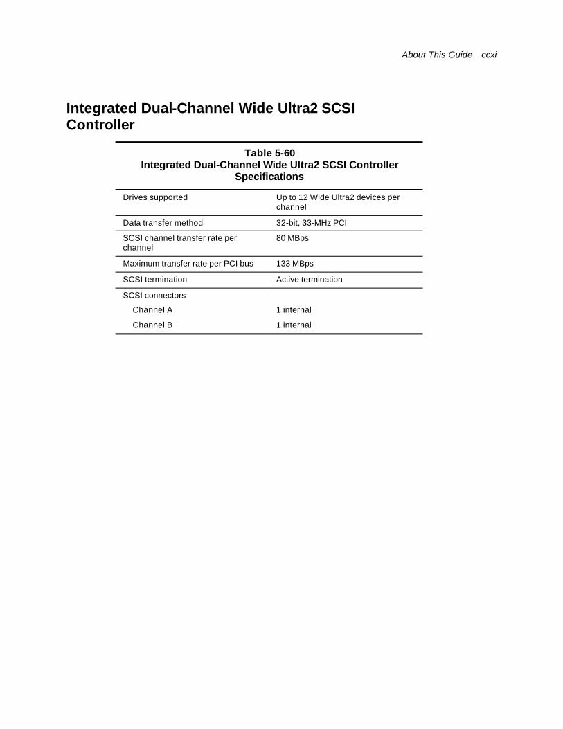
About This Guide ccxi
Integrated Dual-Channel Wide Ultra2 SCSI Controller
Table 5-60 Integrated Dual-Channel Wide Ultra2 SCSI Controller
Specifications
Drives supported Up to 12 Wide Ultra2 devices per channel
Data transfer method 32-bit, 33-MHz PCI
SCSI channel transfer rate per channel
80 MBps
Maximum transfer rate per PCI bus 133 MBps
SCSI termination Active termination
SCSI connectors
Channel A 1 internal
Channel B 1 internal
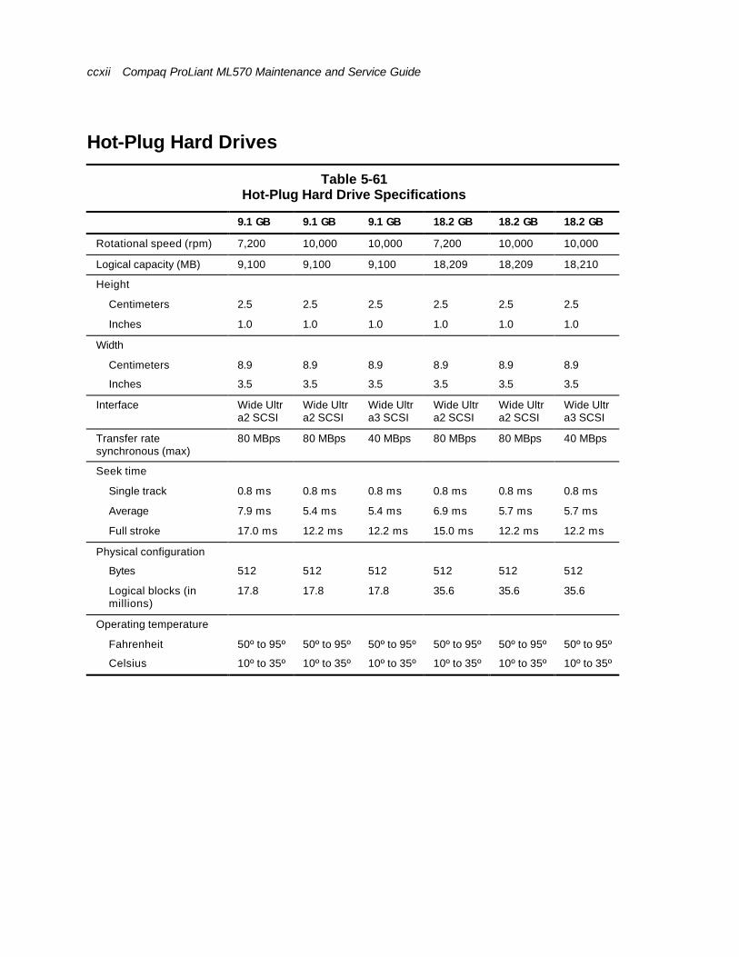
ccxii Compaq ProLiant ML570 Maintenance and Service Guide
Hot-Plug Hard Drives
Table 5-61 Hot-Plug Hard Drive Specifications
9.1 GB 9.1 GB 9.1 GB 18.2 GB 18.2 GB 18.2 GB
Rotational speed (rpm) 7,200 10,000 10,000 7,200 10,000 10,000
Logical capacity (MB) 9,100 9,100 9,100 18,209 18,209 18,210
Height
Centimeters 2.5 2.5 2.5 2.5 2.5 2.5
Inches 1.0 1.0 1.0 1.0 1.0 1.0
Width
Centimeters 8.9 8.9 8.9 8.9 8.9 8.9
Inches 3.5 3.5 3.5 3.5 3.5 3.5
Interface Wide Ultra2 SCSI
Wide Ultra2 SCSI
Wide Ultra3 SCSI
Wide Ultra2 SCSI
Wide Ultra2 SCSI
Wide Ultra3 SCSI
Transfer rate synchronous (max)
80 MBps 80 MBps 40 MBps 80 MBps 80 MBps 40 MBps
Seek time
Single track 0.8 ms 0.8 ms 0.8 ms 0.8 ms 0.8 ms 0.8 ms
Average 7.9 ms 5.4 ms 5.4 ms 6.9 ms 5.7 ms 5.7 ms
Full stroke 17.0 ms 12.2 ms 12.2 ms 15.0 ms 12.2 ms 12.2 ms
Physical configuration
Bytes 512 512 512 512 512 512
Logical blocks (in millions)
17.8 17.8 17.8 35.6 35.6 35.6
Operating temperature
Fahrenheit 50º to 95º 50º to 95º 50º to 95º 50º to 95º 50º to 95º 50º to 95º
Celsius 10º to 35º 10º to 35º 10º to 35º 10º to 35º 10º to 35º 10º to 35º
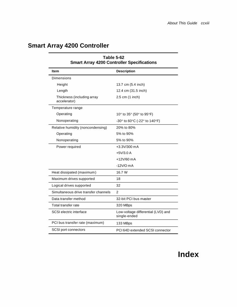
About This Guide ccxiii
Smart Array 4200 Controller
Table 5-62 Smart Array 4200 Controller Specifications
Item Description
Dimensions
Height 13.7 cm (5.4 inch)
Length 12.4 cm (31.5 inch)
Thickness (including array accelerator)
2.5 cm (1 inch)
Temperature range
Operating 10° to 35° (50° to 95°F)
Nonoperating -30° to 60°C (-22° to 140°F)
Relative humidity (noncondensing) 20% to 80%
Operating 5% to 90%
Nonoperating 5% to 90%
Power required +3.3V/300 mA
+5V/3.0 A
+12V/60 mA
-12V/O mA
Heat dissipated (maximum) 16.7 W
Maximum drives supported 18
Logical drives supported 32
Simultaneous drive transfer channels 2
Data transfer method 32-bit PCI bus master
Total transfer rate 320 MBps
SCSI electric interface Low-voltage differential (LVD) and single-ended
PCI bus transfer rate (maximum) 133 MBps
SCSI port connectors PCI 64D extended SCSI connector
Index
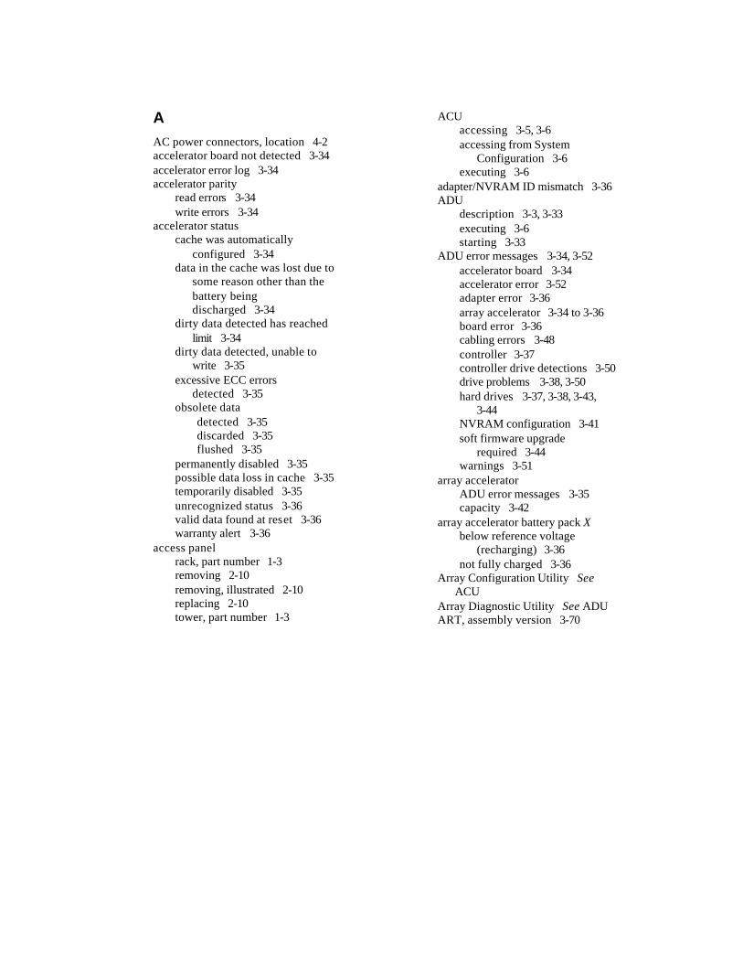
A AC power connectors, location 4-2 accelerator board not detected 3-34 accelerator error log 3-34 accelerator parity
read errors 3-34 write errors 3-34
accelerator status cache was automatically
configured 3-34 data in the cache was lost due to
some reason other than the battery being discharged 3-34
dirty data detected has reached limit 3-34
dirty data detected, unable to write 3-35
excessive ECC errors detected 3-35
obsolete data detected 3-35 discarded 3-35 flushed 3-35
permanently disabled 3-35 possible data loss in cache 3-35 temporarily disabled 3-35 unrecognized status 3-36 valid data found at reset 3-36 warranty alert 3-36
access panel rack, part number 1-3 removing 2-10 removing, illustrated 2-10 replacing 2-10 tower, part number 1-3
ACU accessing 3-5, 3-6 accessing from System
Configuration 3-6 executing 3-6
adapter/NVRAM ID mismatch 3-36 ADU
description 3-3, 3-33 executing 3-6 starting 3-33
ADU error messages 3-34, 3-52 accelerator board 3-34 accelerator error 3-52 adapter error 3-36 array accelerator 3-34 to 3-36 board error 3-36 cabling errors 3-48 controller 3-37 controller drive detections 3-50 drive problems 3-38, 3-50 hard drives 3-37, 3-38, 3-43,
3-44 NVRAM configuration 3-41 soft firmware upgrade
required 3-44 warnings 3-51
array accelerator ADU error messages 3-35 capacity 3-42
array accelerator battery pack X below reference voltage
(recharging) 3-36 not fully charged 3-36
Array Configuration Utility See ACU
Array Diagnostic Utility See ADU ART, assembly version 3-70
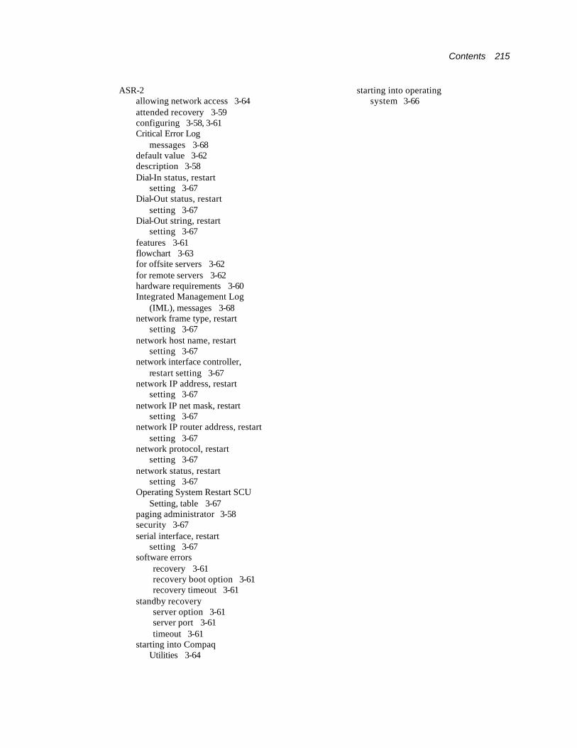
Contents 215
ASR-2 allowing network access 3-64 attended recovery 3-59 configuring 3-58, 3-61 Critical Error Log
messages 3-68 default value 3-62 description 3-58 Dial-In status, restart
setting 3-67 Dial-Out status, restart
setting 3-67 Dial-Out string, restart
setting 3-67 features 3-61 flowchart 3-63 for offsite servers 3-62 for remote servers 3-62 hardware requirements 3-60 Integrated Management Log
(IML), messages 3-68 network frame type, restart
setting 3-67 network host name, restart
setting 3-67 network interface controller,
restart setting 3-67 network IP address, restart
setting 3-67 network IP net mask, restart
setting 3-67 network IP router address, restart
setting 3-67 network protocol, restart
setting 3-67 network status, restart
setting 3-67 Operating System Restart SCU
Setting, table 3-67 paging administrator 3-58 security 3-67 serial interface, restart
setting 3-67 software errors
recovery 3-61 recovery boot option 3-61 recovery timeout 3-61
standby recovery server option 3-61 server port 3-61 timeout 3-61
starting into Compaq Utilities 3-64
starting into operating system 3-66

216 Compaq ProLiant ML570 Maintenance and Service Guide
thermal shutdown 3-61 timer 3-62 unattended recovery 3-59 UPS shutdown 3-61 UPS shutdown threshold 3-61
ASR-2 IML messages 3-68 audible beeps, during POST 3-8 Automatic Data Collection,
defined 3-76 Automatic Revision
Tracking See ART Automatic Server
Recovery-2 See ASR-2 automatic storage reconstruction,
defined 3-71
B backplane board
connectors, illustrated 4-5 part number 1-5 removing 2-54 removing, illustrated 2-54 replacing 2-54
baffle, fan CPU
part number 1-5 removing 2-12 removing, illustrated 2-12 replacing 2-12
hard drive part number 1-5 removing 2-19 removing, illustrated 2-19 replacing 2-19
basket, system fan, part number 1-5 battery
ADU error messages 3-39 connector, identified 4-4 insufficient charge 3-39 part number 1-8 recycling 2-58 removing 2-58 removing, illustrated 2-59 replacing, illustrated 2-59
battery pack X below reference voltage 3-39
beeps, during POST 3-8 bezel
front door part number 1-3 removing 2-9 removing, illustrated 2-9 replacing 2-9
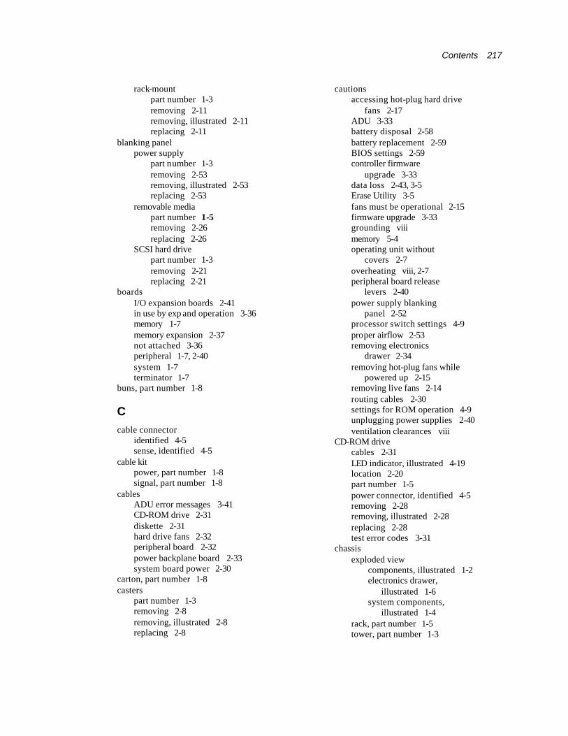
Contents 217
rack-mount part number 1-3 removing 2-11 removing, illustrated 2-11 replacing 2-11
blanking panel power supply
part number 1-3 removing 2-53 removing, illustrated 2-53 replacing 2-53
removable media part number 1-5 removing 2-26 replacing 2-26
SCSI hard drive part number 1-3 removing 2-21 replacing 2-21
boards I/O expansion boards 2-41 in use by exp and operation 3-36 memory 1-7 memory expansion 2-37 not attached 3-36 peripheral 1-7, 2-40 system 1-7 terminator 1-7
buns, part number 1-8
C cable connector
identified 4-5 sense, identified 4-5
cable kit power, part number 1-8 signal, part number 1-8
cables ADU error messages 3-41 CD-ROM drive 2-31 diskette 2-31 hard drive fans 2-32 peripheral board 2-32 power backplane board 2-33 system board power 2-30
carton, part number 1-8 casters
part number 1-3 removing 2-8 removing, illustrated 2-8 replacing 2-8
cautions accessing hot-plug hard drive
fans 2-17 ADU 3-33 battery disposal 2-58 battery replacement 2-59 BIOS settings 2-59 controller firmware
upgrade 3-33 data loss 2-43, 3-5 Erase Utility 3-5 fans must be operational 2-15 firmware upgrade 3-33 grounding viii memory 5-4 operating unit without
covers 2-7 overheating viii, 2-7 peripheral board release
levers 2-40 power supply blanking
panel 2-52 processor switch settings 4-9 proper airflow 2-53 removing electronics
drawer 2-34 removing hot-plug fans while
powered up 2-15 removing live fans 2-14 routing cables 2-30 settings for ROM operation 4-9 unplugging power supplies 2-40 ventilation clearances viii
CD-ROM drive cables 2-31 LED indicator, illustrated 4-19 location 2-20 part number 1-5 power connector, identified 4-5 removing 2-28 removing, illustrated 2-28 replacing 2-28 test error codes 3-31
chassis exploded view
components, illustrated 1-2 electronics drawer,
illustrated 1-6 system components,
illustrated 1-4 rack, part number 1-5 tower, part number 1-3
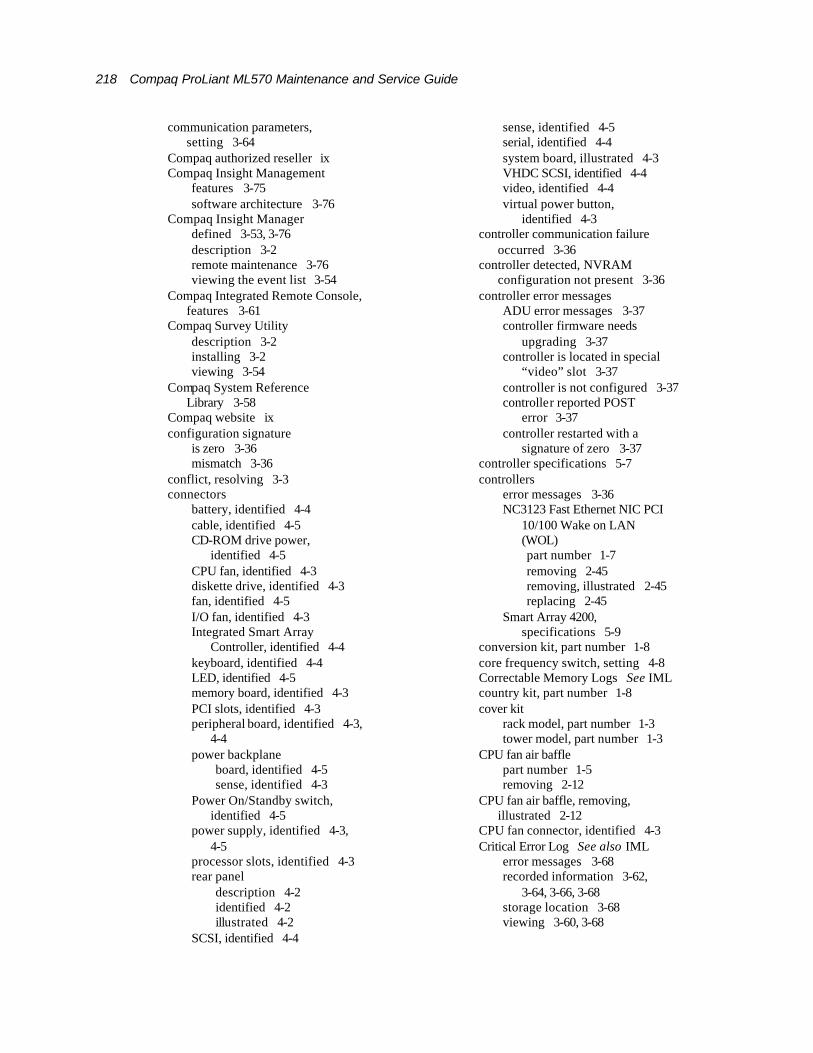
218 Compaq ProLiant ML570 Maintenance and Service Guide
communication parameters, setting 3-64
Compaq authorized reseller ix Compaq Insight Management
features 3-75 software architecture 3-76
Compaq Insight Manager defined 3-53, 3-76 description 3-2 remote maintenance 3-76 viewing the event list 3-54
Compaq Integrated Remote Console, features 3-61
Compaq Survey Utility description 3-2 installing 3-2 viewing 3-54
Compaq System Reference Library 3-58
Compaq website ix configuration signature
is zero 3-36 mismatch 3-36
conflict, resolving 3-3 connectors
battery, identified 4-4 cable, identified 4-5 CD-ROM drive power,
identified 4-5 CPU fan, identified 4-3 diskette drive, identified 4-3 fan, identified 4-5 I/O fan, identified 4-3 Integrated Smart Array
Controller, identified 4-4 keyboard, identified 4-4 LED, identified 4-5 memory board, identified 4-3 PCI slots, identified 4-3 peripheral board, identified 4-3,
4-4 power backplane
board, identified 4-5 sense, identified 4-3
Power On/Standby switch, identified 4-5
power supply, identified 4-3, 4-5
processor slots, identified 4-3 rear panel
description 4-2 identified 4-2 illustrated 4-2
SCSI, identified 4-4
sense, identified 4-5 serial, identified 4-4 system board, illustrated 4-3 VHDC SCSI, identified 4-4 video, identified 4-4 virtual power button,
identified 4-3 controller communication failure
occurred 3-36 controller detected, NVRAM
configuration not present 3-36 controller error messages
ADU error messages 3-37 controller firmware needs
upgrading 3-37 controller is located in special
“video” slot 3-37 controller is not configured 3-37 controller reported POST
error 3-37 controller restarted with a
signature of zero 3-37 controller specifications 5-7 controllers
error messages 3-36 NC3123 Fast Ethernet NIC PCI
10/100 Wake on LAN (WOL) part number 1-7 removing 2-45 removing, illustrated 2-45 replacing 2-45
Smart Array 4200, specifications 5-9
conversion kit, part number 1-8 core frequency switch, setting 4-8 Correctable Memory Logs See IML country kit, part number 1-8 cover kit
rack model, part number 1-3 tower model, part number 1-3
CPU fan air baffle part number 1-5 removing 2-12
CPU fan air baffle, removing, illustrated 2-12
CPU fan connector, identified 4-3 Critical Error Log See also IML
error messages 3-68 recorded information 3-62,
3-64, 3-66, 3-68 storage location 3-68 viewing 3-60, 3-68

Contents 219
Critical Error Log messages See error log messages

220 Compaq ProLiant ML570 Maintenance and Service Guide
D DAAD 3-3 default configuration
determining 3-4 messages 3-4
Diagnostics accessing 3-2, 3-5 defined 3-22 description 3-2 diskette, creating 3-22 error codes 3-22 locating 3-2 overview 3-2 POST error messages 3-8 running 3-22 starting from CD 3-4 starting remotely 3-66 test error codes
CD-ROM drive 3-31 diskette drive 3-27 graphics display unit 3-26 hard drive 3-29, 3-31 keyboard 3-25 memory 3-24 modem 3-28 NIC 3-30 pointing device
interface 3-32 processor 3-23 SCSI hard drive 3-31 SCSI tape drive 3-32 SCSI/IDE CD-ROM
drive 3-31 serial port 3-28 tape drive 3-30, 3-32
Test Error Codes Tables, description 3-22
when to run 3-7 Diagnostics and Utilities menu
Diagnose Drive Array 3-22 Inspect Computer 3-22 Remote Utilities 3-22 Test Computer 3-22 Upgrade Firmware 3-22
Dial-In status, setting 3-65 Dial-Out
status, setting 3-65 string, setting 3-65
DIMMs See also memory installation guidelines 2-36 maximum supported 2-36 part number 1-7 removing 2-39
removing, illustrated 2-39 replacing 2-36, 2-39 socket locations, illustrated 2-36
disable command issued 3-37 disaster recovery, ROMPaq 3-73 diskette drive
connectors, identified 4-3 LED indicator, illustrated 4-19 location 2-20 part number 1-5 removing 2-29 removing, illustrated 2-29 replacing 2-29 specifications 5-4 test error codes 3-27
diskette, creating Diagnostics 3-22 door, front bezel
part number 1-3 removing 2-9 removing, illustrated 2-9 replacing 2-9
drive (bay) X failed 3-38 firmware needs upgrading 3-37 inadvertently replaced 3-38 insufficient capacity for its
configuration 3-37 invalid M&P stamp 3-37 loose cable 3-37 non-Compaq supplied 3-39 replacement drive 3-37 replacement drive marked
OK 3-38 replacing 3-38 undergoing drive recovery 3-38 upload code not readable 3-38
Drive Array Advanced Diagnostics See DAAD
drive bay locations, illustrated 2-20 drive cage
part number 1-3 removing 2-24 removing, illustrated 2-25 replacing 2-25
drive cannot support redundant controller operation 3-41
drive communication ADU error messages 3-50
drive fan cable and cable bracket removing 2-18 removing, illustrated 2-18 replacing 2-18
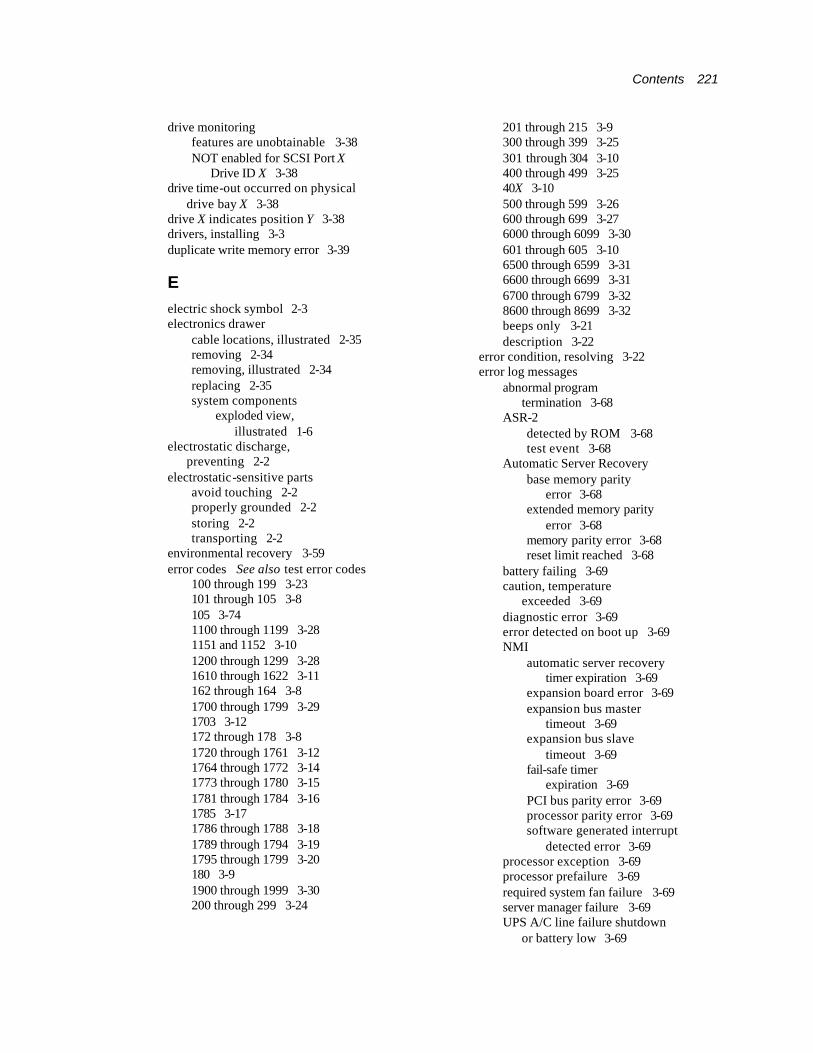
Contents 221
drive monitoring features are unobtainable 3-38 NOT enabled for SCSI Port X
Drive ID X 3-38 drive time-out occurred on physical
drive bay X 3-38 drive X indicates position Y 3-38 drivers, installing 3-3 duplicate write memory error 3-39
E electric shock symbol 2-3 electronics drawer
cable locations, illustrated 2-35 removing 2-34 removing, illustrated 2-34 replacing 2-35 system components
exploded view, illustrated 1-6
electrostatic discharge, preventing 2-2
electrostatic-sensitive parts avoid touching 2-2 properly grounded 2-2 storing 2-2 transporting 2-2
environmental recovery 3-59 error codes See also test error codes
100 through 199 3-23 101 through 105 3-8 105 3-74 1100 through 1199 3-28 1151 and 1152 3-10 1200 through 1299 3-28 1610 through 1622 3-11 162 through 164 3-8 1700 through 1799 3-29 1703 3-12 172 through 178 3-8 1720 through 1761 3-12 1764 through 1772 3-14 1773 through 1780 3-15 1781 through 1784 3-16 1785 3-17 1786 through 1788 3-18 1789 through 1794 3-19 1795 through 1799 3-20 180 3-9 1900 through 1999 3-30 200 through 299 3-24
201 through 215 3-9 300 through 399 3-25 301 through 304 3-10 400 through 499 3-25 40X 3-10 500 through 599 3-26 600 through 699 3-27 6000 through 6099 3-30 601 through 605 3-10 6500 through 6599 3-31 6600 through 6699 3-31 6700 through 6799 3-32 8600 through 8699 3-32 beeps only 3-21 description 3-22
error condition, resolving 3-22 error log messages
abnormal program termination 3-68
ASR-2 detected by ROM 3-68 test event 3-68
Automatic Server Recovery base memory parity
error 3-68 extended memory parity
error 3-68 memory parity error 3-68 reset limit reached 3-68
battery failing 3-69 caution, temperature
exceeded 3-69 diagnostic error 3-69 error detected on boot up 3-69 NMI
automatic server recovery timer expiration 3-69
expansion board error 3-69 expansion bus master
timeout 3-69 expansion bus slave
timeout 3-69 fail-safe timer
expiration 3-69 PCI bus parity error 3-69 processor parity error 3-69 software generated interrupt
detected error 3-69 processor exception 3-69 processor prefailure 3-69 required system fan failure 3-69 server manager failure 3-69 UPS A/C line failure shutdown
or battery low 3-69
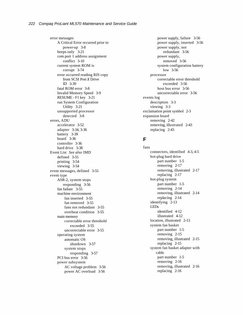
222 Compaq ProLiant ML570 Maintenance and Service Guide
error messages A Critical Error occurred prior to
power-up 3-8 beeps only 3-21 com port 1 address assignment
conflict 3-10 current system ROM is
corrupt 3-74 error occurred reading RIS copy
from SCSI Port X Drive ID 3-39
fatal ROM error 3-8 Invalid Memory Speed 3-9 RESUME - F1 key 3-21 run System Configuration
Utility 3-21 unsupported processor
detected 3-8 errors, ADU
accelerator 3-52 adapter 3-34, 3-36 battery 3-39 board 3-36 controller 3-36 hard drive 3-38
Event List See also IMD defined 3-55 printing 3-54 viewing 3-54
event messages, defined 3-55 event type
ASR-2, system stops responding 3-56
fan failure 3-55 machine environment
fan inserted 3-55 fan removed 3-55 fans not redundant 3-55 overheat condition 3-55
main memory correctable error threshold
exceeded 3-55 uncorrectable error 3-55
operating system automatic OS
shutdown 3-57 system stops
responding 3-57 PCI bus error 3-56 power subsystem
AC voltage problem 3-56 power AC overload 3-56
power supply, failure 3-56 power supply, inserted 3-56 power supply, not
redundant 3-56 power supply,
removed 3-56 system configuration battery
low 3-56 processor
correctable error threshold exceeded 3-56
host bus error 3-56 uncorrectable error 3-56
events log description 3-3 viewing 3-3
exclamation point symbol 2-3 expansion board
removing 2-42 removing, illustrated 2-43 replacing 2-43
F fans
connectors, identified 4-3, 4-5 hot-plug hard drive
part number 1-5 removing 2-17 removing, illustrated 2-17 replacing 2-17
hot-plug system part number 1-5 removing 2-14 removing, illustrated 2-14 replacing 2-14
identifying 2-13 LEDs
identified 4-12 illustrated 4-12
location, illustrated 2-13 system fan basket
part number 1-5 removing 2-15 removing, illustrated 2-15 replacing 2-15
system fan basket adapter with cable part number 1-5 removing 2-16 removing, illustrated 2-16 replacing 2-16

Contents 223
firmware different version 3-41 error, controllers 3-50
flashing the ROM 3-73 flowchart, ASR-2 3-63 front bezel door
part number 1-3 removing 2-9 removing, illustrated 2-9 replacing 2-9
front panel LEDs, illustrated 4-11
G graphics display unit, test error
codes 3-26
H hard drive fan
removing 2-17 removing, illustrated 2-17 replacing 2-17
hard drive fan air baffle, part number 1-5
hard drives 18.2-GB Wide-Ultra, part
number 1-9 9.1-GB Wide-Ultra, part
number 1-9 ADU error messages 3-37,
3-38, 3-43, 3-44, 3-50 blanking panel
part number 1-3 removing 2-21 removing, illustrated 2-21 replacing 2-21
communication problems 3-50 installation order 2-22 LEDs, illustrated 4-20 removal/replacement
guidelines 2-22 removing, illustrated 2-23 replacing 2-23 specifications 5-8 test error codes 3-29, 3-31
hardware kit, part number 1-5 hazard symbol 2-3 hazardous conditions, symbols on
equipment 2-3 hazardous energy circuits
symbol 2-3 Health Driver, description 3-62
help additional sources ix Compaq authorized resellers,
telephone numbers ix Compaq website ix technical support telephone
numbers ix hot-plug drive cage
duplex configuration 2-20 simplex configuration 2-20
hot-plug fans See fans hot-plug hard drives See hard drives hot-plug I/O expansion board
illustrated 2-43 removing 2-43 replacing 2-43
hot-plug power supply LEDs, illustrated 4-18 part number 1-5 removing 2-52
hot-plug SCSI hard drive See also hard drives illustrated 2-23 part number 1-9 removing 2-23 replacing 2-23
http://www.compaq.com ix
I I/O board See system board I/O expansion board
removing 2-42 removing, illustrated 2-43
I/O expansion slots, illustrated 2-41 I/O fan connector, identified 4-3 IDE CD-ROM drive,
specifications 5-5 identify controller data did not match
with NVRAM 3-39 identify errors, ADU error
messages 3-39 identify logical drive data did not
match with NVRAM 3-39 illustrated parts map, part
number 1-8 illustrations
access panel, removing 2-10 backplane board, removing 2-54 bezels
front door, removing 2-9 rack-mount, removing 2-11
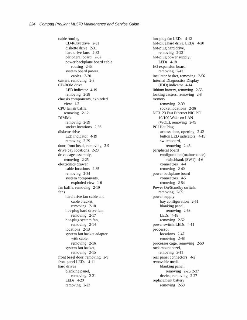
224 Compaq ProLiant ML570 Maintenance and Service Guide
cable routing CD-ROM drive 2-31 diskette drive 2-31 hard drive fans 2-32 peripheral board 2-32 power backplane board cable
routing 2-33 system board power
cables 2-30 casters, removing 2-8 CD-ROM drive
LED indicator 4-19 removing 2-28
chassis components, exploded view 1-2
CPU fan air baffle, removing 2-12
DIMMs removing 2-39 socket locations 2-36
diskette drive LED indicator 4-19 removing 2-29
door, front bezel, removing 2-9 drive bay locations 2-20 drive cage assembly,
removing 2-25 electronics drawer
cable locations 2-35 removing 2-34 system components,
exploded view 1-6 fan baffle, removing 2-19 fans
hard drive fan cable and cable bracket, removing 2-18
hot-plug hard drive fan, removing 2-17
hot-plug system fan, removing 2-14
locations 2-13 system fan basket adapter
with cable, removing 2-16
system fan basket, removing 2-15
front bezel door, removing 2-9 front panel LEDs 4-11 hard drives
blanking panel, removing 2-21
LEDs 4-20 removing 2-23
hot-plug fan LEDs 4-12 hot-plug hard drive, LEDs 4-20 hot-plug hard drive,
removing 2-23 hot-plug power supply,
LEDs 4-18 I/O expansion board,
removing 2-43 insulator basket, removing 2-56 Internal Diagnostics Display
(IDD) indicator 4-14 lithium battery, removing 2-58 locking casters, removing 2-8 memory
removing 2-39 socket locations 2-36
NC3123 Fast Ethernet NIC PCI 10/100 Wake on LAN (WOL), removing 2-45
PCI Hot Plug access door, opening 2-42 button LED indicators 4-15 switchboard,
removing 2-46 peripheral board
configuration (maintenance) switchbank (SW1) 4-6
connectors 4-4 removing 2-40
power backplane board connectors 4-5 removing 2-54
Power On/Standby switch, removing 2-55
power supply bay configuration 2-51 blanking panel,
removing 2-53 LEDs 4-18 removing 2-52
power switch, LEDs 4-11 processor
locations 2-47 removing 2-48
processor cage, removing 2-50 rack-mount bezel,
removing 2-11 rear panel connectors 4-2 removable media
blanking panel, removing 2-26, 2-37
device, removing 2-27 replacement battery
removing 2-59

Contents 225
replacing 2-59
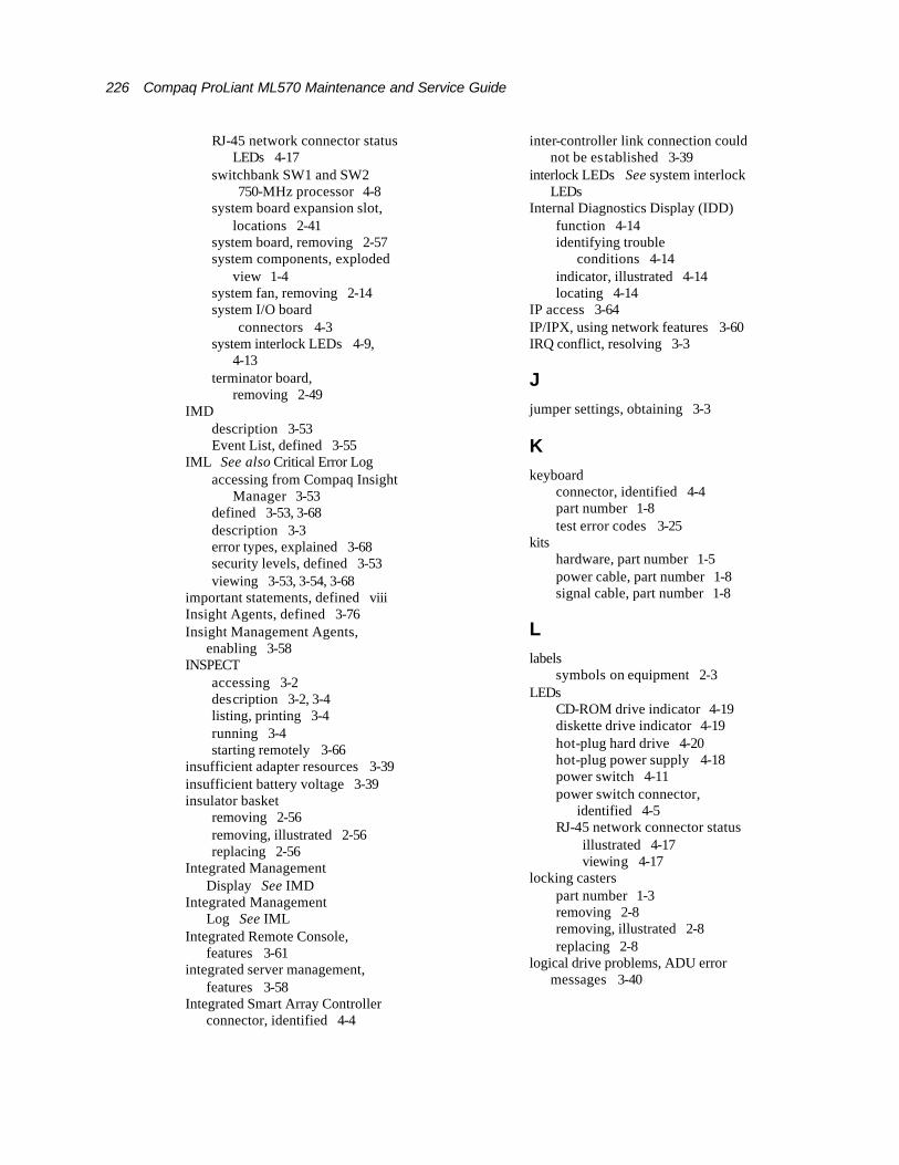
226 Compaq ProLiant ML570 Maintenance and Service Guide
RJ-45 network connector status LEDs 4-17
switchbank SW1 and SW2 750-MHz processor 4-8
system board expansion slot, locations 2-41
system board, removing 2-57 system components, exploded
view 1-4 system fan, removing 2-14 system I/O board
connectors 4-3 system interlock LEDs 4-9,
4-13 terminator board,
removing 2-49 IMD
description 3-53 Event List, defined 3-55
IML See also Critical Error Log accessing from Compaq Insight
Manager 3-53 defined 3-53, 3-68 description 3-3 error types, explained 3-68 security levels, defined 3-53 viewing 3-53, 3-54, 3-68
important statements, defined viii Insight Agents, defined 3-76 Insight Management Agents,
enabling 3-58 INSPECT
accessing 3-2 description 3-2, 3-4 listing, printing 3-4 running 3-4 starting remotely 3-66
insufficient adapter resources 3-39 insufficient battery voltage 3-39 insulator basket
removing 2-56 removing, illustrated 2-56 replacing 2-56
Integrated Management Display See IMD
Integrated Management Log See IML
Integrated Remote Console, features 3-61
integrated server management, features 3-58
Integrated Smart Array Controller connector, identified 4-4
inter-controller link connection could not be es tablished 3-39
interlock LEDs See system interlock LEDs
Internal Diagnostics Display (IDD) function 4-14 identifying trouble
conditions 4-14 indicator, illustrated 4-14 locating 4-14
IP access 3-64 IP/IPX, using network features 3-60 IRQ conflict, resolving 3-3
J jumper settings, obtaining 3-3
K keyboard
connector, identified 4-4 part number 1-8 test error codes 3-25
kits hardware, part number 1-5 power cable, part number 1-8 signal cable, part number 1-8
L labels
symbols on equipment 2-3 LEDs
CD-ROM drive indicator 4-19 diskette drive indicator 4-19 hot-plug hard drive 4-20 hot-plug power supply 4-18 power switch 4-11 power switch connector,
identified 4-5 RJ-45 network connector status
illustrated 4-17 viewing 4-17
locking casters part number 1-3 removing 2-8 removing, illustrated 2-8 replacing 2-8
logical drive problems, ADU error messages 3-40
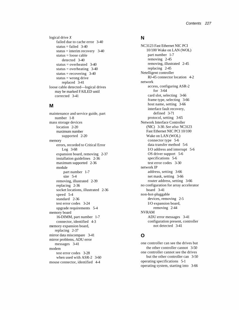
Contents 227
logical drive X failed due to cache error 3-40 status = failed 3-40 status = interim recovery 3-40 status = loose cable
detected 3-40 status = overheated 3-40 status = overheating 3-40 status = recovering 3-40 status = wrong drive
replaced 3-41 loose cable detected—logical drives
may be marked FAILED until corrected 3-41
M maintenance and service guide, part
number 1-8 mass storage devices
location 2-20 maximum number
supported 2-20 memory
errors, recorded to Critical Error Log 3-68
expansion board, removing 2-37 installation guidelines 2-36 maximum supported 2-36 module
part number 1-7 size 5-4
removing, illustrated 2-39 replacing 2-36 socket locations, illustrated 2-36 speed 5-4 standard 2-36 test error codes 3-24 upgrade requirements 5-4
memory board 16-DIMM, part number 1-7 connector, identified 4-3
memory expansion board, replacing 2-37
mirror data miscompare 3-41 mirror problems, ADU error
messages 3-41 modem
test error codes 3-28 when used with ASR-2 3-60
mouse connector, identified 4-4
N NC3123 Fast Ethernet NIC PCI
10/100 Wake on LAN (WOL) part number 1-7 removing 2-45 removing, illustrated 2-45 replacing 2-45
Netelligent controller RJ-45 connector location 4-2
network access, configuring ASR-2
for 3-64 card slot, selecting 3-66 frame type, selecting 3-66 host name, setting 3-66 interface fault recovery,
defined 3-71 protocol, setting 3-65
Network Interface Controller (NIC) 3-30. See also NC3123 Fast Ethernet NIC PCI 10/100 Wake on LAN (WOL) connector type 5-6 data transfer method 5-6 I/O address and interrupt 5-6 OS driver support 5-6 specifications 5-6 test error codes 3-30
network IP address, setting 3-66 net mask, setting 3-66 router address, setting 3-66
no configuration for array accelerator board 3-41
non-hot-pluggable devices, removing 2-5 I/O expansion board,
removing 2-44 NVRAM
ADU error messages 3-41 configuration present, controller
not detected 3-41
O one controller can see the drives but
the other controller cannot 3-50 one controller cannot see the drives
but the other controller can 3-50 operating specifications 5-1 operating system, starting into 3-66
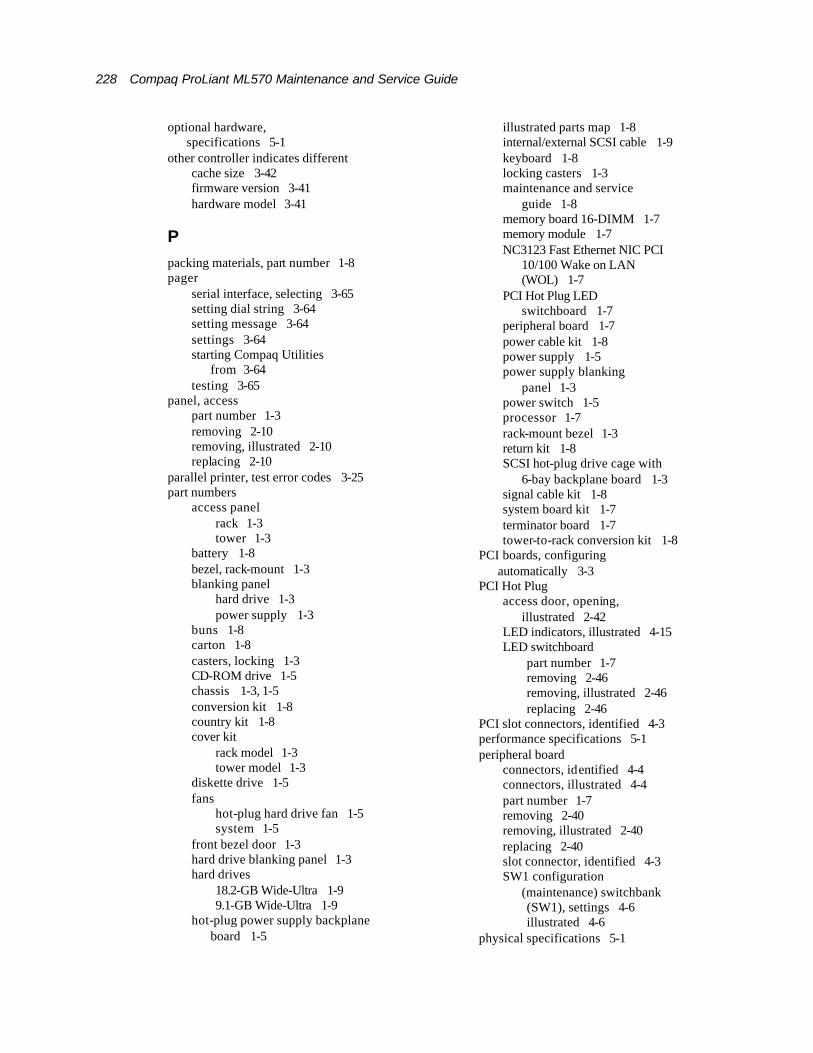
228 Compaq ProLiant ML570 Maintenance and Service Guide
optional hardware, specifications 5-1
other controller indicates different cache size 3-42 firmware version 3-41 hardware model 3-41
P packing materials, part number 1-8 pager
serial interface, selecting 3-65 setting dial string 3-64 setting message 3-64 settings 3-64 starting Compaq Utilities
from 3-64 testing 3-65
panel, access part number 1-3 removing 2-10 removing, illustrated 2-10 replacing 2-10
parallel printer, test error codes 3-25 part numbers
access panel rack 1-3 tower 1-3
battery 1-8 bezel, rack-mount 1-3 blanking panel
hard drive 1-3 power supply 1-3
buns 1-8 carton 1-8 casters, locking 1-3 CD-ROM drive 1-5 chassis 1-3, 1-5 conversion kit 1-8 country kit 1-8 cover kit
rack model 1-3 tower model 1-3
diskette drive 1-5 fans
hot-plug hard drive fan 1-5 system 1-5
front bezel door 1-3 hard drive blanking panel 1-3 hard drives
18.2-GB Wide-Ultra 1-9 9.1-GB Wide-Ultra 1-9
hot-plug power supply backplane board 1-5
illustrated parts map 1-8 internal/external SCSI cable 1-9 keyboard 1-8 locking casters 1-3 maintenance and service
guide 1-8 memory board 16-DIMM 1-7 memory module 1-7 NC3123 Fast Ethernet NIC PCI
10/100 Wake on LAN (WOL) 1-7
PCI Hot Plug LED switchboard 1-7
peripheral board 1-7 power cable kit 1-8 power supply 1-5 power supply blanking
panel 1-3 power switch 1-5 processor 1-7 rack-mount bezel 1-3 return kit 1-8 SCSI hot-plug drive cage with
6-bay backplane board 1-3 signal cable kit 1-8 system board kit 1-7 terminator board 1-7 tower-to-rack conversion kit 1-8
PCI boards, configuring automatically 3-3
PCI Hot Plug access door, opening,
illustrated 2-42 LED indicators, illustrated 4-15 LED switchboard
part number 1-7 removing 2-46 removing, illustrated 2-46 replacing 2-46
PCI slot connectors, identified 4-3 performance specifications 5-1 peripheral board
connectors, identified 4-4 connectors, illustrated 4-4 part number 1-7 removing 2-40 removing, illustrated 2-40 replacing 2-40 slot connector, identified 4-3 SW1 configuration
(maintenance) switchbank (SW1), settings 4-6 illustrated 4-6
physical specifications 5-1
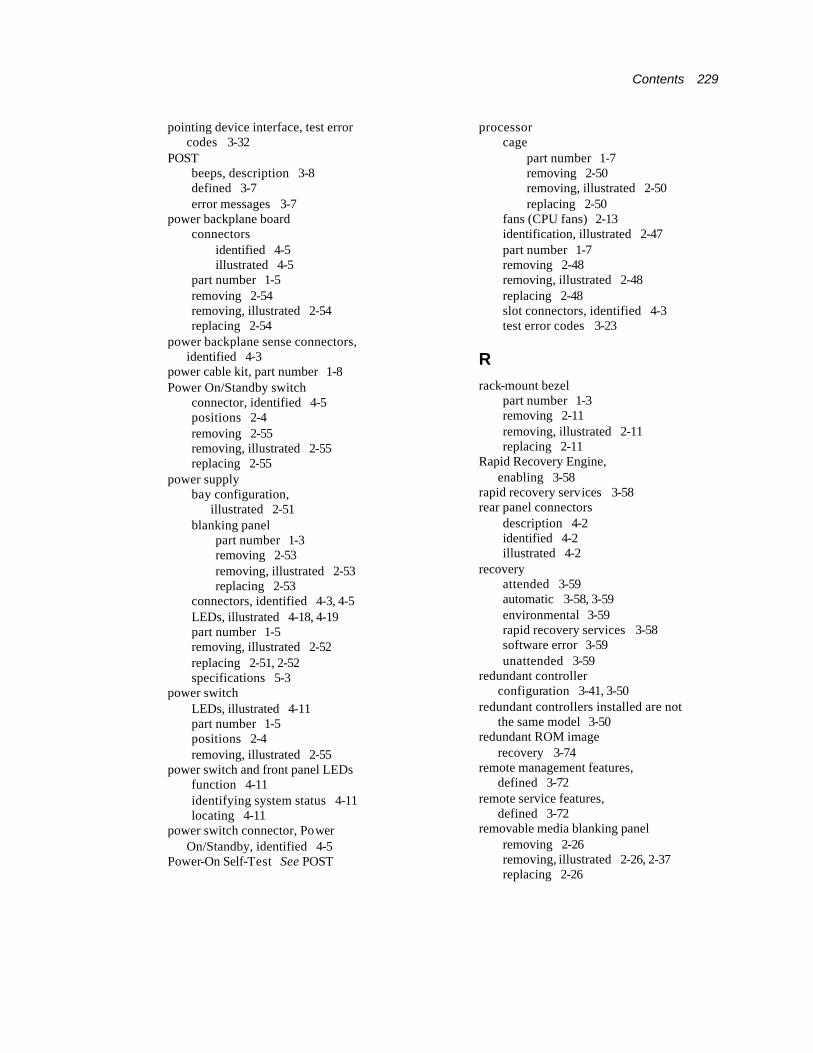
Contents 229
pointing device interface, test error codes 3-32
POST beeps, description 3-8 defined 3-7 error messages 3-7
power backplane board connectors
identified 4-5 illustrated 4-5
part number 1-5 removing 2-54 removing, illustrated 2-54 replacing 2-54
power backplane sense connectors, identified 4-3
power cable kit, part number 1-8 Power On/Standby switch
connector, identified 4-5 positions 2-4 removing 2-55 removing, illustrated 2-55 replacing 2-55
power supply bay configuration,
illustrated 2-51 blanking panel
part number 1-3 removing 2-53 removing, illustrated 2-53 replacing 2-53
connectors, identified 4-3, 4-5 LEDs, illustrated 4-18, 4-19 part number 1-5 removing, illustrated 2-52 replacing 2-51, 2-52 specifications 5-3
power switch LEDs, illustrated 4-11 part number 1-5 positions 2-4 removing, illustrated 2-55
power switch and front panel LEDs function 4-11 identifying system status 4-11 locating 4-11
power switch connector, Power On/Standby, identified 4-5
Power-On Self-Test See POST
processor cage
part number 1-7 removing 2-50 removing, illustrated 2-50 replacing 2-50
fans (CPU fans) 2-13 identification, illustrated 2-47 part number 1-7 removing 2-48 removing, illustrated 2-48 replacing 2-48 slot connectors, identified 4-3 test error codes 3-23
R rack-mount bezel
part number 1-3 removing 2-11 removing, illustrated 2-11 replacing 2-11
Rapid Recovery Engine, enabling 3-58
rapid recovery services 3-58 rear panel connectors
description 4-2 identified 4-2 illustrated 4-2
recovery attended 3-59 automatic 3-58, 3-59 environmental 3-59 rapid recovery services 3-58 software error 3-59 unattended 3-59
redundant controller configuration 3-41, 3-50
redundant controllers installed are not the same model 3-50
redundant ROM image recovery 3-74
remote management features, defined 3-72
remote service features, defined 3-72
removable media blanking panel removing 2-26 removing, illustrated 2-26, 2-37 replacing 2-26

230 Compaq ProLiant ML570 Maintenance and Service Guide
removable media device removing 2-27 removing, illustrated 2-27 replacing 2-27
removable media drive, location 2-20
removal and replacement procedures, preparation 2-4
replacement battery, part number 1-8
resource conflict, resolving 3-3 return kit, part number 1-8 Revision History Table
accessing 3-70 defined 3-70 storage location 3-70
RIS copies between drives do not match 3-42
RJ-45 connector location 4-2 network connector status LEDs
illustrated 4-17 viewing 4-17
receptacle symbol 2-3 ROM
disaster recovery 3-73 flashing 3-73
ROMPaq disaster recovery 3-73 Firmware Upgrade Utility,
accessing 3-5 recovery options 3-73
S screwdriver symbol 2-3 SCSI cable
internal/external, part number 1-9
option board, part number 1-9 SCSI CD-ROM drives See
CD-ROM drives SCSI connectors, identified 4-4 SCSI hard drive blanking panel,
replacing 2-21 SCSI hard drives See hot-plug SCSI
hard drives. See hard drives SCSI hot-plug drive cage with 6-bay
backplane board, part number 1-3
SCSI port X, Drive ID Y failed – REPLACE (failure
message) 3-42 firmware needs upgrading 3-42 has exceeded threshold(s) 3-42 is not stamped for
monitoring 3-43 may have a loose
connection 3-43 RIS copies within this drive do
not match 3-43 S.M.A.R.T. predictive failure
errors have been detected in the (factory) Monitor and Performance data 3-43
S.M.A.R.T. predictive failure errors have been detected in the Monitor and Performance data 3-44
was replaced on a good volume: (failure message) 3-44
SCSI tape drives See tape drives SDRAM DIMM See memory security levels
Caution, defined 3-53 Critical, defined 3-53 Repaired, defined 3-53 Status, defined 3-53
security, ASR-2 3-67 sense connector, identified 4-5 serial connectors, identified 4-4 serial port, test error codes 3-28 Server Health Logs 3-68 server power, removing 2-5 set configuration command
issued 3-44 shipping materials, part number 1-8 signal cable kit, part number 1-8 Smart Array 4200 controller
data transfer method 5-9 dimensions 5-9 drives supported 5-9 height 5-9 power requirements 5-9 SCSI port connectors 5-9 specifications 5-9 temperature range 5-9 thickness 5-9 transfer rate 5-9
SmartStart and Support Software CD contents 3-5 running utilities 3-5 running utilities from 3-6 starting from 3-4

Contents 231
soft firmware upgrade required 3-44 software error
recovery from 3-59, 3-61 recovery start option 3-61 recovery timeout 3-61
spare parts list 1-7 specifications
controller 5-7 diskette drive 5-4 hard drives 5-8 IDE CD-ROM drive 5-5 NC3123 Fast Ethernet NIC PCI
10/100 Wake on LAN (WOL) 5-6
operating 5-1 optional hardware 5-1 performance 5-1 physical 5-1 power supply 5-3 Smart Array 4200 controller 5-9 system unit 5-2
standby recovery server option 3-61 server port 3-61 timeout 3-61
standby, effects 2-4 storage automatic reconstruction,
defined 3-71 storage enclosure on SCSI bus X
has a cabling error 3-45 indicated a door alert 3-45 indicated a power supply
failure 3-45 indicated an overheated
condition 3-46 indicated that a fan module is
unplugged 3-47 indicated that the fan
failed 3-46 indicated that the fan is
degraded 3-46 is unsupported with its current
firmware version 3-46 wide SCSI transfer failed 3-47
storage fault recovery tracking, defined 3-71
Survey Utility, viewing 3-54 SW1 See peripheral board SW6 See system board
ID/miscellaneous switch
swapped cables or configuration error detected cables may be
interchanged 3-48 configuration information on the
attached drive is not backward compatible with the controller’s firmware 3-49
configured array of drives was moved from another controller 3-47
drive rearrangement was attempted while an expand operation was running 3-48
maximum logical volume count X was exceeded 3-49
unsupported drive arrangement was attempted 3-48
switchbank SW1 and SW2 750-MHz processor,
illustrated 4-8 switches
core frequency, settings 4-8 diskette start feature,
settings 4-6 lock configuration, settings 4-6 maintenance, settings 4-6 power on password, settings 4-6 Power On/Standby
removing, illustrated 2-55 power, part number 1-5 system board ID/miscellaneous
(SW6), identified 4-9 tower-to-rack conversion,
settings 4-6 video, settings 4-6
symbols in text vii on equipment 2-3
system board connectors
description 4-3 illustrated 4-3
electronics drawer, removing 2-34
error, slot indicator 3-50 expansion slots, locations,
illustrated 2-41 ID/miscellaneous switch (SW6),
illustrated 4-9

232 Compaq ProLiant ML570 Maintenance and Service Guide
kit, part number 1-7 removing 2-57 removing, illustrated 2-57 replacing 2-57 unable to identify slot and
controller correspondence 3-50
system components exploded view, illustrated 1-4
system configuration clearing invalid system
configuration 4-7 determining 3-4 erasing 4-7
System Configuration CD, starting from 3-4
System Configuration Utility accessing 3-5 description 3-3 executing 3-6 messages 3-4 running 3-3 selecting Diagnostics from 3-22 starting remotely 3-66
system fan part number 1-5 removing 2-14 removing, illustrated 2-14 replacing 2-14
system fan basket part number 1-5 removing 2-15 removing, illustrated 2-15 replacing 2-15
system fan basket adapter with cable part number 1-5 removing 2-16 removing, illustrated 2-16 replacing 2-16
system halted 3-12 system interlock LEDs
function 4-13 identifying interlock fault 4-13 illustrated 4-13 locating 4-13
system partition, accessing utilities from 3-5
system unit, specifications 5-2
T tables
1.44-MB Diskette Drive Specifications 5-4
32X Max IDE CD-ROM Drive Specifications 5-5
Array Diagnostic Utility (ADU) Error Messages 3-34
ASR-2 IML or Critical Error Log Messages 3-68
Automatic Server Recovery-2 (ASR-2) Features 3-61
Chassis Components Spare Parts List 1-3
Compaq Network Interface Controller Boards Test Error Codes 3-30
Compaq Servers Remote Management Features 3-72
Compaq System Configuration Utility Pager Settings for Starting into Compaq Utilities 3-64
Diagnostic Tools 3-2 Diskette and CD-ROM
Cables 2-31 Diskette Drive Test Error
Codes 3-27 Dual Inline Memory Module
(DIMM) Combinations 2-38 Event Messages 3-55 Front Panel Status LED
Indicators 4-11 Graphics Display Unit Test Error
Codes 3-26 Hard Drive Test Error
Codes 3-29 Hot-Plug Fan Diagnostic LED
Indicators 4-12 Hot-Plug Fan Locations 2-13 Hot-Plug Hard Drive
Specifications 5-8 Hot-Plug Power Supply
Diagnostic LED Indicators 4-18
Hot-Plug Power Supply Specifications 5-3
Hot-Plug SCSI Hard Drive LED Indicators 4-20
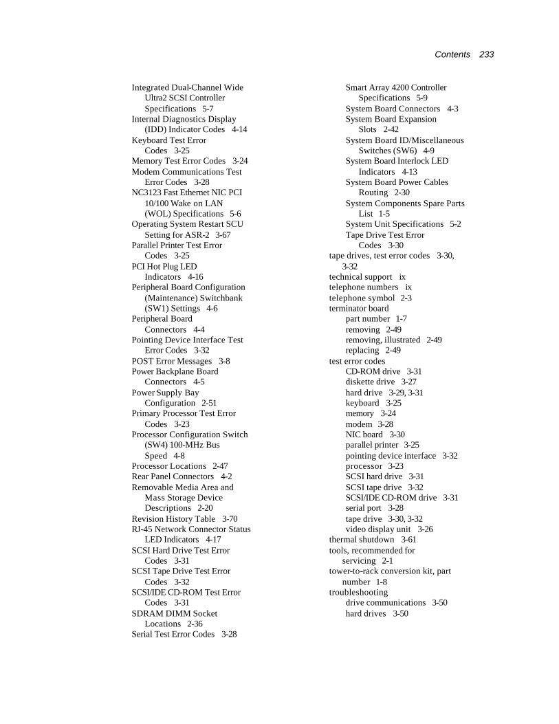
Contents 233
Integrated Dual-Channel Wide Ultra2 SCSI Controller Specifications 5-7
Internal Diagnostics Display (IDD) Indicator Codes 4-14
Keyboard Test Error Codes 3-25
Memory Test Error Codes 3-24 Modem Communications Test
Error Codes 3-28 NC3123 Fast Ethernet NIC PCI
10/100 Wake on LAN (WOL) Specifications 5-6
Operating System Restart SCU Setting for ASR-2 3-67
Parallel Printer Test Error Codes 3-25
PCI Hot Plug LED Indicators 4-16
Peripheral Board Configuration (Maintenance) Switchbank (SW1) Settings 4-6
Peripheral Board Connectors 4-4
Pointing Device Interface Test Error Codes 3-32
POST Error Messages 3-8 Power Backplane Board
Connectors 4-5 Power Supply Bay
Configuration 2-51 Primary Processor Test Error
Codes 3-23 Processor Configuration Switch
(SW4) 100-MHz Bus Speed 4-8
Processor Locations 2-47 Rear Panel Connectors 4-2 Removable Media Area and
Mass Storage Device Descriptions 2-20
Revision History Table 3-70 RJ-45 Network Connector Status
LED Indicators 4-17 SCSI Hard Drive Test Error
Codes 3-31 SCSI Tape Drive Test Error
Codes 3-32 SCSI/IDE CD-ROM Test Error
Codes 3-31 SDRAM DIMM Socket
Locations 2-36 Serial Test Error Codes 3-28
Smart Array 4200 Controller Specifications 5-9
System Board Connectors 4-3 System Board Expansion
Slots 2-42 System Board ID/Miscellaneous
Switches (SW6) 4-9 System Board Interlock LED
Indicators 4-13 System Board Power Cables
Routing 2-30 System Components Spare Parts
List 1-5 System Unit Specifications 5-2 Tape Drive Test Error
Codes 3-30 tape drives, test error codes 3-30,
3-32 technical support ix telephone numbers ix telephone symbol 2-3 terminator board
part number 1-7 removing 2-49 removing, illustrated 2-49 replacing 2-49
test error codes CD-ROM drive 3-31 diskette drive 3-27 hard drive 3-29, 3-31 keyboard 3-25 memory 3-24 modem 3-28 NIC board 3-30 parallel printer 3-25 pointing device interface 3-32 processor 3-23 SCSI hard drive 3-31 SCSI tape drive 3-32 SCSI/IDE CD-ROM drive 3-31 serial port 3-28 tape drive 3-30, 3-32 video display unit 3-26
thermal shutdown 3-61 tools, recommended for
servicing 2-1 tower-to-rack conversion kit, part
number 1-8 troubleshooting
drive communications 3-50 hard drives 3-50
234 Compaq ProLiant ML570 Maintenance and Service Guide
U unable to communicate with drive on
SCSI port X, drive ID Y 3-50 unable to retrieve identify controller
data 3-51 unknown disable code 3-51 unrecoverable read error 3-51 UPS shutdown threshold 3-61 utilities
accessing 3-5 ADU
accessing 3-5 description 3-3 executing 3-6
allowing network access to 3-65 Array Configuration
accessing 3-5, 3-6 executing 3-6
Compaq configuring server to
start 3-60 Insight Manager,
description 3-2, 3-75 running remotely 3-60 Survey Utility,
description 3-2 Survey Utility,
installing 3-2 System Reference
Library 3-58 creating diskette versions 3-6 DAAD
accessing remotely 3-72 description 3-3
Diagnostics accessing 3-5 menu choices 3-22 selecting from System
Configuration Utility 3-22
Firmware Upgrade, accessing 3-5
Health Driver 3-62 IML Management Utility,
defined 3-54 INSPECT
accessing 3-2 description 3-2, 3-4 listing, printing 3-4 running 3-4
Integrated Management Log, description 3-3
ROMPaq Firmware Upgrade, accessing 3-5
running from SmartStart and Support Software CD 3-6
starting from ASR-2 3-64 Survey, defined 3-54 System Configuration
accessing 3-5 description 3-3 executing 3-6 running 3-3 starting from pager 3-64
V VHDC SCSI connectors,
identified 4-4 video connector, identified 4-4 virtual power button, identified 4-3
W WARNING - Drive Write Cache is
enabled on X 3-51 warning bit detected 3-51 warnings
ADU error messages 3-51 allow cooling 2-9 component level repairs viii electric shock viii, 2-3, 2-5, 2-7 equipment damage viii, 2-1,
2-5, 2-6, 2-7, 2-18 grounding 2-7 grounding plug viii hazardous energy levels viii,
2-1, 2-18 heavy weight 2-3 hot surfaces 2-3, 2-7 multiple sources of power 2-3 peripheral board, removing 2-58 personal injury viii, 2-1, 2-5,
2-6, 2-18 personal injury or damage to the
equipment 2-15 power cords 2-5 qualified service personnel 2-4 rack stability viii, 2-6 reduce risk of injury 2-4
wrist strap, using 2-2 write memory error 3-52 wrong accelerator 3-52 www.compaq.com ix


