ML-003 – Additional Sheet 1 Moray Offshore...
14
1 ML-003 – Additional Sheet 1 Moray Offshore Renewables Ltd Offshore Transmission Infrastructure Section 5 (b) Description of the proposed schedule of work The indicative programme below provides a high level construction programme for the three wind farms (Telford, Stevenson and MacColl) and associated transmission infrastructure. It shows some variations to the indicative programme included within the MORL 2012 ES (Chapter 2.2 of the Telford, Stevenson, MacColl Wind Farms and Associated Transmission Infrastructure Environmental Statement), but it is consistent with the worst case scenarios assessed in the ES. The key issues which have driven the changes to the indicative programme were: (1) the decision by Scottish Electric & Transmission to impose a moratorium on new connections to the grid until 2018 (MORL’s original connection was in 2016); and (2) the legislative changes as part of the Electricity Market Reform by UK Government which affects when and how projects are delivered and phased. A construction schedule of 24 hours per day, 7 days a week and 365 days per year is anticipated. The indicative programme shows that installation of the modified offshore transmission works is expected to commence in 2018. Offshore cabling works and AC Offshore Substation Platforms (OSPs) installation will be completed either in 2018 or 2019, depending upon the offshore wind farm construction schedule. The actual offshore installation period is anticipated to take less than a month per OSP. A detailed construction method statement, including schedule, will be submitted with a construction management plan in advance of construction works commencing. MORL Installation Programme FEED & COMPETITION BY DESIGN Place Contracts Offshore Export Cables Installation AC Offshore Substation Installation 2014 Q1 Q2 Q3 Q4 Onshore Substation Onshore Export Cables Installation FINAL INVESTMENT DECISION FABRICATION & CONSTRUCTION Turbine Foundation and Substructure Install Inter Array Cables Installation Turbine Installation & Commissioning Q3 Q4 Q4 Q2 Q3 Q4 Q1 Q2 Q3 Q2 Q3 Q4 Q1 Q2 Q1 Q2 Q3 Q4 Q1 2015 2016 2017 2018 System Commissioning 1ST GENERATION 1/2 CAPACITY INSTALLED FULL CAPACITY INSTALLED 2021 Q1 Q2 Q3 Q4 2019 2020 Q1 Q2 Q3 Q4 Q1 Final Investment Grid Availability 1st Gen 1/2 Capacity Installed Full Capacity Sys Sys 2
Transcript of ML-003 – Additional Sheet 1 Moray Offshore...

1
ML-003 – Additional Sheet 1
Moray Offshore Renewables Ltd Offshore Transmission Infrastructure
Section 5 (b) Description of the proposed schedule of work
The indicative programme below provides a high level construction programme for the three wind farms (Telford, Stevenson and MacColl) and associated transmission infrastructure. It shows some variations to the indicative programme included within the MORL 2012 ES (Chapter 2.2 of the Telford, Stevenson, MacColl Wind Farms and Associated Transmission Infrastructure Environmental Statement), but it is consistent with the worst case scenarios assessed in the ES.
The key issues which have driven the changes to the indicative programme were: (1) the decision by Scottish Electric & Transmission to impose a moratorium on new connections to the grid until 2018 (MORL’s original connection was in 2016); and (2) the legislative changes as part of the Electricity Market Reform by UK Government which affects when and how projects are delivered and phased.
A construction schedule of 24 hours per day, 7 days a week and 365 days per year is anticipated.
The indicative programme shows that installation of the modified offshore transmission works is expected to commence in 2018. Offshore cabling works and AC Offshore Substation Platforms (OSPs) installation will be completed either in 2018 or 2019, depending upon the offshore wind farm construction schedule. The actual offshore installation period is anticipated to take less than a month per OSP.
A detailed construction method statement, including schedule, will be submitted with a construction management plan in advance of construction works commencing.
MORL Installation Programme
FEED & COMPETITION BY DESIGN
Place Contracts
0 0 0 0 0 0 0 0 0 0 0 0 0 0 0 0 0 0 0 0 0 0 0 0 0 0 0 0 0 0 0 0 0 0 0 0 0 0 0 0 0 0 0 0 0 0 0 0 0 0 0 0 0 0 0 0 0 0 0 0 0 0 0 0 0 0 0 0 0 0 0 0
0 0 0 0 0 0 0 0 0 0 0 0 0 0 0 0 0 0 0 0 0 0 0 0 0 0 0 0 0 0 0 0 0 0 0 0 0 0 0 0 0 0 0 0 0 0 0 0 0 0
0 0 0 0 0 0 0 0 0 0 0 0 0 0 0 0 0 0 0 0 0 0 0 0 0 0 0 0 0 0 0 0
0 0 0 0 0 0 0 0 0 0 0 0 0 0 0 0 0 0 0 0 0 0 0 0 0 0 0 0 0 0 0 0 0 0 0 0 0 0 0 0 0 0 0 0 0 0 0 0 0 0 0 0 0 0 0 0 0 0 0 0 0 0 0 0 0 0 0 0 0 0 0 0
0 0 0 0 0 0 0 0 0 0 0 0 0 0 0 0 0 0 0 0 0 0 0 0 0 0 0 0 0 0 0 0 0 0 0 0 0 0 0 0 0 0 0 0 0 0 0
0 0 0 0 0 0 0 0 0 0 0 0 0 0 0 0 0 0 0 0 0 0 0 0 0 0
0 0 0 0 0 0 0 0 0 0 0 0 0 0 0 0 0 0 0 0 0 0 0 0 0 0 0 0 0 0 0 0 0 0 0 0 0 0 0 0 0 0 0 0 0 0 0 0 0 0 0 0 0 0 0 0 0 0 0 0 0 0 0 0 0 0 0 0 0 0 0 0
0 0 0 0 0 0 0 0 0 0 0 0 0 0 0 0 0 0 0 0 0 0
0 0 0 0 0 0 0 0 0 0 0 0 0 0 0 0 0 0 0 0 0 0 0 0 0 0
0 0 0 0 0 0 0 0 0 0 0 0 0 0 0 0 0 0 0 0 0 0 0 0 0 0 0 0 0 0 0 0 0 0 0 0 0 0 0 0 0 0 0 0 0 0
0 0 0 0 0 0 0 0 0 0 0 0 0 0 0 0 0 0 0 0 0 0 0
0 0 0 0 0 0 0 0 0 0 0 0 0 0 0 0 0 0 0 0 0
0 0 0 0 0 0 0 0 0 0 0 0 0 0 0 0 0 0 0 0 0
0 0 0 0 0 0 0 0 0 0 0 0 0 0 0 0 0 0 0 0 0 0 0
0 0 0 0 0 0 0 0 0 0 0 0 0 0 0 0 0 0 0 0 0 0 0 0 0 0 0 0 0 0
0 0 0 0 0 0 0 0 0 0 0 0 0 0 0 0 0 0 0 0 0 0 0
0 0 0 0 0 0 0 0 0 0 0 0 0 0 0 0 0 0 0 0 0 0
0 0 0 0 0 0 0 0 0 0 0 0 0 0 0 0 0 0 0 0 0
Offshore Export Cables Installation
AC Offshore Substation Installation
2014Q1 Q2 Q3 Q4
Onshore Substation
Onshore Export Cables Installation
FINAL INVESTMENT DECISION
FABRICATION & CONSTRUCTION
Turbine Foundation and Substructure Install
Inter Array Cables Installation
Turbine Installation & Commissioning
Q3 Q4 Q4Q2 Q3 Q4 Q1 Q2 Q3Q2 Q3 Q4 Q1 Q2Q1 Q2 Q3 Q4 Q1
2015 2016 2017 2018
System Commissioning
1ST GENERATION
1/2 CAPACITY INSTALLED
FULL CAPACITY INSTALLED
2021Q1 Q2 Q3 Q4
2019 2020Q1 Q2 Q3 Q4Q1
Final Investment
Grid Availability
1st Gen
1/2 Capacity
Installed
Full
Capacity
Sys Sys 2

2
ML-003 – Additional Sheet 2
Moray Offshore Renewables Ltd Offshore Transmission Infrastructure
Section 5 (c) Types of work proposed
Offshore Transmission Infrastructure parameters
Infrastructure Type Parameter Parameter Range
AC OSPs
Number required 2
Indicative topside width x length 100 x 100 m
Indicative maximum height above LAT 70 m
Substructure & foundation
for OSPs: Steel Lattice
Jackets with Pin Piles or
Suction Caissons Or Steel
Lattice Jack–up with Pin
Piles or Suction Caissons
Jacket base width Up to 100 m
Number of legs / piles or suction caissons
(Jacket) Up to 8 legged / 8 piles
Number of legs / piles or suction caissons
(Jack up) 4 legged / 16 piles
Diameter of piles 3 m
Length of piles 60 m
Scour protection around each leg plus pile
diameter 16 m
Diameter of suction caissons 20 m
Scour protection around each leg plus
suction caisson diameter 40 m
Inter–platform cabling Voltage 220 kV
Offshore Grid Connection
Export cabling (offshore)
Cable configuration 4 cables
Cable separation distance 4 x water depth (200 to
800 m), as per regulation
Voltage of cabling 220 kV
Entry / exit method from OSPs J tube
Target burial depth in seabed 1 m
Protection where target burial not achieved Concrete mattresses or
rock placement
Cable corridor width Four x up to 6 m trench
Length to shore
75 km from the centre of
the EDA with micrositing
allowance

3
ML-003 – Additional Sheet 3
Moray Offshore Renewables Ltd Offshore Transmission Infrastructure
Section 7 (c) Method Statement
A geophysical and geotechnical survey campaign will be carried out of the modified offshore transmission infrastructure (OfTI) corridor during 2014 to identify appropriate areas for installation of cables and platforms. The extent of the surveyed areas can be seen in the enclosed offshore transmission works plan. All OfTI will be located either within the Eastern Development Are (EDA) (as shown in Figure 1.1-1 of the Offshore Transmission Infrastructure Environmental Report) or within an offshore export cable corridor outwith the EDA.
AC Offshore Substation Platforms
Up to two alternating current (AC) offshore substation platforms (OSPs) will be required to collect the power generated by the three wind farms within the EDA. The exact locations of the OSPs are not currently known but will be within the EDA boundary The AC OSPs are enclosed structures housing heavy electrical equipment such as transformers, switchgear and control systems. The function of the AC OSPs is to transform the electricity generated by the turbines from voltages of 33–66 kV to 220 kV for export to the AC OSPs.
Foundations and Substructures for the AC OSPs
The AC OSPs will be supported by substructures and foundations, of which there are four concepts identified as suitable for the area within the EDA:
Jacket with pin piles;
Jacket with suction caissons;
Jack–up with pin piles; and
Jack–up with suction caissons.
The choice of which concept is more appropriate is dependent upon the ground conditions within a particular site.
Jackets with Pin Piles or Suction Caissons
The jacket substructure with pin pile foundations is similar to that of a wind turbine (as described within Chapter 2.2 of the MORL ES). However, the jacket structure required to support an AC OSP will have up to 6 legs (see Plate 1). The alternative suction caisson foundation would be an open–ended steel cylinder up to 20 m diameter attached to each leg (see Plate 2 below). The principle is that water is sucked out of the cylinder which then embeds itself in a sandy seabed to a depth of up to 20 m. This option cannot be used in many locations within EDA because only 10 % of the seabed in this area is suitable for this concept.

4
Plate 1 – Pin Pile Foundations
Plate 2 – Suction Caisson Foundations
Jack–ups with Pin Piles or Suction Caissons
The jack–up concept will have either pin pile or suction caisson foundations similar to those described above for the jackets concept. The jack–up substructure consists of a topside box with four support legs that can be raised or lowered using a powerful jacking system operating between each leg and the hull. Water ballast is taken by the jacking system to ensure the legs are fully loaded and secure in the seabed. At the base of each leg a ‘spud can’, such as a steel cone which penetrates the seabed, may be fitted. For long–term stability it may be necessary to install four pin piles per leg, each pin pile of up to 3 m diameter. Alternatively a suction caisson of 20 m diameter can provide stability. The area

5
around the legs will require scour protection. Corrosion protection is likely to take the form of cathodic protection, painting and mechanical removal of deposits, there is potential for use of corrosion inhibitor chemicals inside the J tubes. An assessment of the requirement for corrosion protection and management of deposits on the substructures will be made later.
Inter–Platform Cabling
Cabling at 220 kV may be required to connect the two AC OSPs. Cables will be buried or protected as described in the ‘Offshore Installation’ section below.
Export Cable
AC export cables will be required to connect the AC OSPs to the chosen grid connection point. Two 220 kV export cables per AC OSP will be required resulting in a total of up to four export cables. There will be up to four trenches (one per cable) with a maximum trench affected width of 6 m in the offshore section.
Export Cable Route
The AC OSPs will be located within the EDA. The site selection work for the cable route identified Sandend or Inverboydie as potential landfall areas, which would allow the export cable to be taken onshore to the final connection point at New Deer. The width of the surveyed offshore export cable route, within which the export cables will be installed, is variable depending on the water depth, seabed conditions and seabed features. The cable corridor search area outwith the EDA is up to approximately 15 km in width as shown in the enclosed offshore transmission works plan.
For the subsea portion of the route, the AC cable would be buried to a target depth of 1 m based on site–specific seabed conditions. Where adequate burial cannot be achieved alternative protection methods, such as mattresses or rock placement will be used.
The cables will be spaced apart to reduce the potential for damage by unexpected activities such as anchor drag, and to allow safe repair of adjacent cables. The distance between the cables or cable bundles is expected to be four times the water depth, based on current industry best practice. From the bathymetric conditions anticipated in the surveyed area (based on admiralty charts and survey data) this will result in a cable separation of approximately 200 to 800 m.
Offshore Installation
The following section describes the installation procedures likely to be utilised for installation of the modified OfTI. Final installation methods are subject to detailed engineering design and may be adapted based on the technology selected and technical advances.
Jacket with Pin–Piles or Suction Caissons
A jack–up barge or other suitable lift vessel would be used to transport the jackets to site and a crane would be used to install the substructure. Where pin–piles are used as the foundation technique, the piles may be installed before (pre–piling) or after (post–piling) the jacket is installed. For pre–piled foundations, a template is placed on the seabed to ensure the piles are installed in the correct locations. The template is then removed and moved to the next location and the jacket is landed onto the piles. For post–piling, the piles are installed through pile sleeves located at each corner of the jacket. Impact piling is the most common method of installing piles, using a piling hammer from a suitable vessel (e.g. jack–up). In some cases, it may be possible to drill the post–hole. However, this

6
method is not currently commercially viable for large–scale use and is currently only expected to be used in exceptional circumstances. Another option would be to combine the two techniques in a drive–drill–drive pattern. This is usually used in areas with very hard geological strata and it is not currently expected to be used within any of the EDA unless piling alone has been unsuccessful.
Suction caissons may also be used as the foundation of the jacket legs. These may be installed either by pushing the caisson into the seabed or by creating a negative pressure within the skirt by “sucking the water out” which secures the caisson to the seabed.
Where required, grout will be used to provide a strong connection between jacket and pile. The grout will be installed using the pile sleeve and ROV observation. After grouting, scour protection may need to be installed around each leg / pile depending on local conditions. This may be controlled rock placement, concrete mattresses or anti–scour matting.
Jack–up Concept
The concept of using a jack–up to support an OSP offers the advantage that the entire jack–up including the topsides equipment box can be built in a shipyard. Once complete the hull of the jack–up, which is essentially a water tight steel box containing the equipment can be floated out of dry dock at the shipyard to the site with the four legs fully extended above the hull.
The principle of the jack up is that the support legs can be raised or lowered using a jacking system operating between each leg and the hull. On arrival at site the legs would be jacked down to contact the seabed, then the full weight of the hull plus water ballast would be taken by the jacking system to ensure the legs are fully loaded and secure in the seabed. After this the hydraulic jacking system would elevate the hull up the legs to its intended elevation. At the base of each leg a ‘spud can’ would be fitted, typically a steel cone.
To ensure stability over the operational life of the platform, it may be necessary to install four pin pile at the foot of each leg. This would be grouted to secure the connection to the leg structure. The J tubes for the OSP cable entries / exits will be positioned after the jacking operation is complete. Alternatively a suction caisson would be utilised as an alternative seabed fixing method, installed using similar methodology as described in the jacket concept section above.
Dimensions of the jack up concept would be within the envelope described for the jacket substructures.
Offshore Substation and Converter Platforms
Where the AC OSPs have a jacket substructure, the platform topsides are installed independently of the substructure themselves. The topsides will be transported to site and lifted into position using a crane from a heavy lift vessel. The topsides may be installed as a single unit or in separate modules.
Offshore Cabling
The following section describes cabling installation relevant to the transmission infrastructure where the cables are installed offshore (i.e. from the intertidal area to the OSPs and between OSPs).
Cable Burial
Cable lay vessels are used to lay and bury inter–platform and offshore export cables. Further analysis will be carried out on the site seabed conditions as part of the cable protection and burial study. The study will consider the technically and economically achievable burial depths based in the EDA (where the OSPs will be located) and export cable corridor site specific ground conditions. The target
7
burial depth is 1 m. For most of the offshore export cable route it is expected that the cables will be in trenches for protection. However, for the section leading to shore it is likely that the seabed will contain areas of rock at, or close to the surface which is potentially unsuitable for trenching, so cables may be laid on the seabed. Where this occurs the cable will be protected by graded rock placement, concrete mattresses or other suitable protective coverings.
The available techniques for creating the cable trenches are ploughing, jetting, jet–assisted plough, tracked devices or mechanical cutting. The technique used is chosen so it is suitable for the seabed conditions. A short technical description of these techniques is detailed below:
Ploughing – A cable plough is a device towed behind a vessel. The plough sits on the seabed and as it is pulled forward, curved steel plough blades are driven into the seabed creating a trench.
Jetting – Jetting is performed by a remotely operated vehicle which sits on the seabed on a tracked wheel system. The jetting vehicle receives power and control signals via an umbilical from a surface vessel. The jetting vehicle lowers jetting swords into the seabed fluidising the substrate with high pressure water jets into the swords. The vehicle drives itself along the cable route using its tracked wheel system with the swords and the water jets creating a trench as it travels forward.
The operation itself may take one of two forms:
Combined lay and bury: where the cable trench is created and immediately after the cable is laid in the trench using the same tool and therefore in the same operation; and
Post–lay burial: where the cable is laid on the seabed in one continuous operation. Upon completion of this a second operation is done to create the trench into which the cable will fall through gravity.
Jet assisted plough – This technique is basically a hybrid method incorporating ploughing and jetting. Cable ploughs are towed by a vessel and at the surface specialised nozzles introduce water at the soil interface, fluidising the substrate, reducing the stresses involved in this process.
Tracked devices – These have tracks (like bulldozers) and are deployed on the seabed and usually powered by an umbilical from a vessel. The tracked vehicle can carry a range of equipment for trenching such as mechanical rock cutters or jetting equipment.
Mechanical cutting – Is used to cut a trench through rock or very stiff clay. It would be deployed on a tracked device and consist of rotating cutting heads.
Each cable laying operation is expected to be done continuously without the requirement for splicing. The maximum speed of progress is in the range 300 to 500 m / hr. In difficult conditions (e.g. very stiff clay or rocky sea beds), progress will be slower.
For either method used, the degree to which the trench naturally back–fills depends on the nature of the seabed and local metocean conditions or scour protection will be laid where cables cannot be buried to the target depth.
Where the cable has to cross existing infrastructure, such as other cables, special arrangements will be required. For example: a layer of concrete mattresses or grout bags may be fitted over the top of the existing cable. The new cable would be run over this protective layer and then itself protected with a further layer of mattresses or grout bags. The methodology for crossing arrangements will be developed in agreement with third party cable owner / operators where relevant.
The export cables will typically be laid starting at the landfall and finishing at the offshore site. It is likely that the two first export cables from the first AC OSP will be installed separately from the second

8
set of two AC export cables. The second cable lay operation may be done directly after completion of the first two cables or a number of years after the first installation is complete dependant on the capacity phasing of the wind farm.
The route would be aligned parallel with the first cable route but sufficiently separated to avoid damage (see section Export Cable Route).
Cable Pull–in
At each OSP it will be necessary to pull a number of cables depending on the size of the array strings. A row of J tubes will be pre–installed along sides of the substructure to accept the cable from each of several array strings. Typically a system using messenger wires and cable guides allows pull–in to proceed without diver intervention. Once the cable is pulled in and secured, any exposed areas may be protected (e.g. by mattresses or rock dumping).
Export Cable Landfall
The techniques which could be used for the offshore export cable landfall and intertidal area include open cut trenching, ploughing, dredging, mechanical cutters and horizontal directional drilling (HDD).
Open cut trenching consists of excavating a trench across the landfall location and down below low tide level to a point where marine vessels and equipment can operate and continue trenching. Construction of a temporary causeway across the beach and down through the low tide level may be required to provide a base for excavation equipment to dig a trench alongside the causeway. On the beach or in shallow water a back–hoe dredger may be used. In deeper water specialist dredging / trenching equipment could be used.
In the case of sandy beaches, it may be possible to locate a marine trenching plough above high tide connected to the cable installation vessel lying near to shore. The vessel can then pull the trenching plough down the beach and out to sea installing the cable in the foot of the trench as it goes.
If rocky conditions are encountered, it may be possible to use a mechanical cutter which uses a rotary cutting wheel to excavate a narrow trench. Such machines may operate above or below water.
HDD may be used to avoid cutting an open trench. This involves drilling a hole from the landward side of the landfall to a point below low tide where marine equipment can operate. The diameter of the hole is sized to take a conduit through which the cable(s) are pulled. The maximum distance of cable pull depends on the design strength of the cable. For standard cables, the limit of pull and, therefore, of the HDD approach is 500 m. However, specially strengthened cable can be used to extend this distance to 1 km in exceptional circumstances.
Construction Phase Safety Zones
In accordance with the Electricity (Offshore Generating Stations) (Safety Zones) (Application Procedures and Control of Access) Regulations 2007, it is expected that a 500 m safety zone around each OSP and cable installation activity will be applied for under Section 95 of the Energy Act 2004 during the period of construction. In order to minimise disruption to navigation by users of the sea, safety zones are expected to be established around such areas of the total site that have activities actually taking place at a given time. As such the safety zones are expected to follow throughout the different areas of the site as construction work is undertaken. The exact locations are to be determined at a later stage and would be notified to mariners. Safety Zones in place on the Project will be implemented and communicated though standard protocol (i.e. Notice to Mariners).

9
Transport to Site
It is anticipated that most infrastructure elements will be transported to site or the construction port by sea although some elements may be transported via road before transfer to a vessel. The construction port has not yet been identified, although it is expected to be based on the eastern coast of Scotland or northern England.
Operation and Maintenance
Operational activities, such as monitoring of OSP activity, will either be carried out primarily from a shore base or from an offshore location.
Maintenance activities will include the following types of activities:
Major interventions include overhauls of OSP equipment which may be required periodically during the operational life of the wind farms. Unplanned failures within OSP equipment or cables may also require major repairs, which require the use of equipment and methods originally used to install the relevant infrastructure;
Preventive maintenance comprising scheduled activities including plant and equipment scheduled maintenance, necessary safety inspections and testing of safety related equipment, inspections of primary and secondary structures, scheduled overhauls;
Corrective maintenance to address equipment failures, primary alarms, or actions arising from results of inspections; and
Opportunistic maintenance in cases where maintenance personnel and access vessels are available at site and some precautionary inspections or preventive maintenance can usefully be carried out.
The types of vessels that will be used during operation are yet to be decided and will be provided within a construction method statement that will be submitted in advance of works commencing.
Operational Safety Zones
Under the Electricity (Offshore Generating Stations) (Safety Zones) (Application Procedures and Control of Access) Regulations 2007, the standard dimensions for a safety zone during the operational phase is a radius of 50 m measured from the outer edge at sea level of the proposed or existing OSP. Depending on the safety case, a larger area may be requested in the application to DECC.
Decommissioning
Under the Energy Act (2004), a wind farm and associated transmission infrastructure must be decommissioned at the end of their lifetimes. Guidance is currently available on decommissioning liabilities and standards (DECC, 2011) and a preliminary decommissioning programme has been prepared to support the Section 36 consent applications (see MORL ES for details). However, the decommissioning programme would be updated in accordance with relevant legislation and guidance available at the time of decommissioning.

10
Decommissioning will most likely include the removal of non buried–elements (OSPs) and associated substructures. It is anticipated that buried elements such as foundations and cables will be left in situ.
11
ML-003 – Additional Sheet 4
Moray Offshore Renewables Ltd Offshore Transmission Infrastructure
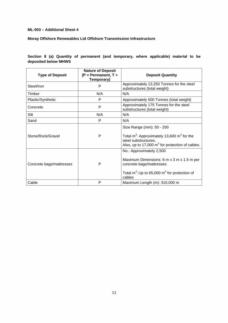
Section 8 (a) Quantity of permanent (and temporary, where applicable) material to be deposited below MHWS
Type of Deposit Nature of Deposit
(P = Permanent, T = Temporary)
Deposit Quantity
Steel/Iron P Approximately 13,250 Tonnes for the steel substructures (total weight)
Timber N/A N/A
Plastic/Synthetic P Approximately 500 Tonnes (total weight)
Concrete P Approximately 175 Tonnes for the steel substructures (total weight)
Silt N/A N/A
Sand P N/A
Stone/Rock/Gravel P
Size Range (mm): 50 - 200 Total m3: Approximately 13,600 m3 for the steel substructures. Also, up to 17,000 m3 for protection of cables.
Concrete bags/mattresses P
No.: Approximately 2,500 Maximum Dimensions: 6 m x 3 m x 1.5 m per concrete bags/mattresses Total m3: Up to 65,000 m3 for protection of cables
Cable P Maximum Length (m): 310,000 m

460000
460000
480000
480000
500000
500000
520000
520000
540000
540000
560000
560000
6400000
6400000
6420000
6420000
6440000
6440000
6460000
6460000
6480000
6480000
2°0'
0"W
2°20
'0"W
2°40
'0"W
3°0'
0"W
3°20
'0"W
3°40
'0"W
58°20'0"N
58°0'0"N
57°40'0"N
0 10,000 20,000 Meters ¯
© Scottish National Heritage
SeaZone Solutions Limited, 2005 [012009.001] ©British Crown Copyright, 2005. All Rights Reserved.
Moray Offshore Renewables Ltd ©
2014. This document is the property of contractors and sub-contractors and shall not be reproduced nor transm
itted without prior written approval.
REF: 8460001-PSL0060-MOR-MAP-002
Produced: RHReviewed: CRApproved: SP
Moray OffshoreRenewables Ltd
Moray Offshore Renewables Ltd
Revision: A
Moray OffshoreTransmission Works
1:400,000Horizontal Scale:
Geodetic Parameters: WGS84 UTM Zone 30N
A3 Chart
Date: 03/04/2014
KEY
Offshore Transmission WorksLicence Area
Special Protected Area (SPA)
Special Area of Conservation (SAC)
Site of Special Scientific Interest (SSSI)
RAMSAR

Moray Offshore Transmission Boundary Coordinates
X-Easting (m) Y-Northing (m) Lat (D.d) Long (D.d) Lat (DM.m) Long (DM.m) Lat (DM S) Long (DM S)
1 505117.1271 6436034.636 58.065759° -2.913270° 58° 3.945539' -2° 54.796212' 58° 3' 56.732364" -2° 54' 47.772738"
2 506316 6437015 58.074549° -2.892924° 58° 4.472947' -2° 53.575457' 58° 4' 28.376796" -2° 53' 34.527415"
3 507040 6437767 58.081293° -2.880628° 58° 4.877557' -2° 52.837664' 58° 4' 52.653396" -2° 52' 50.259828"
4 507795 6438707 58.089723° -2.867795° 58° 5.383378' -2° 52.067673' 58° 5' 23.002692" -2° 52' 4.060384"
5 508442 6439746 58.099043° -2.856784° 58° 5.942598' -2° 51.407033' 58° 5' 56.555880" -2° 51' 24.422000"
6 508994 6440936 58.109721° -2.847374° 58° 6.583252' -2° 50.842425' 58° 6' 34.995132" -2° 50' 50.545489"
7 509349 6441886 58.118246° -2.841312° 58° 7.094777' -2° 50.478695' 58° 7' 5.686608" -2° 50' 28.721713"
8 509560 6442760 58.126092° -2.837694° 58° 7.565514' -2° 50.261666' 58° 7' 33.930840" -2° 50' 15.699973"
9 509672 6443375 58.131613° -2.835768° 58° 7.896798' -2° 50.146053' 58° 7' 53.807880" -2° 50' 8.763151"
10 509788 6444177 58.138814° -2.833764° 58° 8.328850' -2° 50.025858' 58° 8' 19.731012" -2° 50' 1.551451"
11 509820 6445320 58.149080° -2.833173° 58° 8.944780' -2° 49.990369' 58° 8' 56.686812" -2° 49' 59.422116"
12 509733 6446526 58.159914° -2.834601° 58° 9.594819' -2° 50.076034' 58° 9' 35.689140" -2° 50' 4.562023"
13 509562 6447386 58.167642° -2.837471° 58° 10.058503' -2° 50.248275' 58° 10' 3.510156" -2° 50' 14.896489"
14 509370 6448231 58.175235° -2.840701° 58° 10.514126' -2° 50.442048' 58° 10' 30.847548" -2° 50' 26.522869"
15 509202 6448727 58.179694° -2.843537° 58° 10.781635' -2° 50.612243' 58° 10' 46.898112" -2° 50' 36.734582"
16 509202 6448727 58.179694° -2.843537° 58° 10.781635' -2° 50.612243' 58° 10' 46.898112" -2° 50' 36.734582"
17 509071 6449114 58.183173° -2.845750° 58° 10.990354' -2° 50.744984' 58° 10' 59.421252" -2° 50' 44.699024"
18 508647 6450078 58.191840° -2.852924° 58° 11.510370' -2° 51.175438' 58° 11' 30.622200" -2° 51' 10.526278"
19 508084 6451087 58.200913° -2.862465° 58° 12.054766' -2° 51.747896' 58° 12' 3.285936" -2° 51' 44.873777"
20 507393.029 6452043.959 58.209520° -2.874190° 58° 12.571202' -2° 52.451411' 58° 12' 34.272144" -2° 52' 27.084637"
21 507463.6426 6452106.119 58.210077° -2.872987° 58° 12.604630' -2° 52.379192' 58° 12' 36.277776" -2° 52' 22.751508"
22 507750.5357 6452367.393 58.212419° -2.868096° 58° 12.745133' -2° 52.085736' 58° 12' 44.708004" -2° 52' 5.144174"
23 508031.9212 6452634.274 58.214811° -2.863298° 58° 12.888655' -2° 51.797855' 58° 12' 53.319276" -2° 51' 47.871288"
24 508308.5806 6452905.669 58.217243° -2.858579° 58° 13.034603' -2° 51.514752' 58° 13' 2.076168" -2° 51' 30.885095"
25 508581.6053 6453181.658 58.219717° -2.853922° 58° 13.183021' -2° 51.235312' 58° 13' 10.981236" -2° 51' 14.118700"
26 508849.0458 6453462.234 58.222232° -2.849359° 58° 13.333906' -2° 50.961526' 58° 13' 20.034372" -2° 50' 57.691561"
27 509110.9028 6453747.396 58.224788° -2.844890° 58° 13.487261' -2° 50.693394' 58° 13' 29.235648" -2° 50' 41.603658"
28 509173.1901 6453816.378 58.225406° -2.843827° 58° 13.524358' -2° 50.629606' 58° 13' 31.461456" -2° 50' 37.776365"
29 509386.4617 6454057.299 58.227565° -2.840186° 58° 13.653921' -2° 50.411167' 58° 13' 39.235260" -2° 50' 24.670021"
30 509639.0202 6454351.629 58.230203° -2.835874° 58° 13.812209' -2° 50.152432' 58° 13' 48.732528" -2° 50' 9.145939"
31 509886.0736 6454650.461 58.232882° -2.831655° 58° 13.972921' -2° 49.899272' 58° 13' 58.375272" -2° 49' 53.956340"
32 510127.5473 6454953.011 58.235594° -2.827529° 58° 14.135637' -2° 49.651766' 58° 14' 8.138220" -2° 49' 39.105944"
33 510364.4516 6455260.062 58.238346° -2.823481° 58° 14.300776' -2° 49.408879' 58° 14' 18.046572" -2° 49' 24.532716"
34 510409.2609 6455319.797 58.238882° -2.822715° 58° 14.332904' -2° 49.362929' 58° 14' 19.974228" -2° 49' 21.775742"
35 510489.7529 6455411.81 58.239706° -2.821340° 58° 14.382376' -2° 49.280427' 58° 14' 22.942536" -2° 49' 16.825595"
36 510742.1432 6455706.033 58.242343° -2.817028° 58° 14.540567' -2° 49.021692' 58° 14' 32.434008" -2° 49' 1.301502"
37 510989.0285 6456004.831 58.245020° -2.812809° 58° 14.701224' -2° 48.768532' 58° 14' 42.073440" -2° 48' 46.111910"
38 511107.9004 6456153.825 58.246356° -2.810777° 58° 14.781338' -2° 48.646611' 58° 14' 46.880268" -2° 48' 38.796631"
39 511231.2672 6456308.284 58.247740° -2.808668° 58° 14.864388' -2° 48.520070' 58° 14' 51.863280" -2° 48' 31.204188"
40 511467.9268 6456615.297 58.250491° -2.804621° 58° 15.029471' -2° 48.277262' 58° 15' 1.768248" -2° 48' 16.635726"
41 511699.083 6456926.879 58.253284° -2.800667° 58° 15.197017' -2° 48.040029' 58° 15' 11.821032" -2° 48' 2.401751"
42 511924.6618 6457242.173 58.256109° -2.796807° 58° 15.366565' -2° 47.808450' 58° 15' 21.993912" -2° 47' 48.506971"
43 512144.663 6457561.021 58.258967° -2.793042° 58° 15.538031' -2° 47.582525' 58° 15' 32.281848" -2° 47' 34.951484"
44 512359.1631 6457884.433 58.261866° -2.789370° 58° 15.711959' -2° 47.362174' 58° 15' 42.717528" -2° 47' 21.730448"
45 512568.0901 6458210.616 58.264790° -2.785791° 58° 15.887383' -2° 47.147478' 58° 15' 53.242956" -2° 47' 8.848655"
46 512771.5169 6458541.282 58.267754° -2.782306° 58° 16.065226' -2° 46.938356' 58° 16' 3.913572" -2° 46' 56.301362"
47 512968.4393 6458874.713 58.270743° -2.778931° 58° 16.244566' -2° 46.735843' 58° 16' 14.673936" -2° 46' 44.150567"
48 513159.7875 6459211.766 58.273764° -2.775650° 58° 16.425861' -2° 46.538985' 58° 16' 25.551660" -2° 46' 32.339089"
49 513345.6413 6459552.44 58.276819° -2.772462° 58° 16.609113' -2° 46.347702' 58° 16' 36.546780" -2° 46' 20.862091"
50 513525.0715 6459895.797 58.279897° -2.769382° 58° 16.793817' -2° 46.162947' 58° 16' 47.629020" -2° 46' 9.776849"
51 513698.8529 6460242.848 58.283009° -2.766399° 58° 16.980519' -2° 45.983928' 58° 16' 58.831140" -2° 45' 59.035666"
52 513798.0728 6460448.436 58.284852° -2.764695° 58° 17.091123' -2° 45.881676' 58° 17' 5.467380" -2° 45' 52.900582"
53 513887.1453 6460637.48 58.286547° -2.763164° 58° 17.192830' -2° 45.789857' 58° 17' 11.569776" -2° 45' 47.391433"
54 514049.0149 6460989.887 58.289707° -2.760382° 58° 17.382431' -2° 45.622941' 58° 17' 22.945848" -2° 45' 37.376489"
55 514204.387 6461345.048 58.292892° -2.757711° 58° 17.573525' -2° 45.462636' 58° 17' 34.411524" -2° 45' 27.758135"
56 514352.4076 6461702.802 58.296100° -2.755164° 58° 17.766028' -2° 45.309816' 58° 17' 45.961692" -2° 45' 18.588935"
57 514495.8787 6462063.314 58.299334° -2.752694° 58° 17.960023' -2° 45.161615' 58° 17' 57.601356" -2° 45' 9.696870"
58 514631.923 6462426.571 58.302592° -2.750350° 58° 18.155509' -2° 45.020979' 58° 18' 9.330516" -2° 45' 1.258726"
59 514761.4796 6462791.563 58.305866° -2.748116° 58° 18.351941' -2° 44.886953' 58° 18' 21.116448" -2° 44' 53.217161"
60 514885.5573 6463159.228 58.309164° -2.745975° 58° 18.549821' -2° 44.758501' 58° 18' 32.989248" -2° 44' 45.510076"
61 515002.2948 6463528.625 58.312477° -2.743959° 58° 18.748648' -2° 44.637535' 58° 18' 44.918856" -2° 44' 38.252126"
62 515113.482 6463899.912 58.315808° -2.742037° 58° 18.948502' -2° 44.522224' 58° 18' 56.910132" -2° 44' 31.333420"
63 515217.3294 6464273.783 58.319163° -2.740240° 58° 19.149763' -2° 44.414397' 58° 19' 8.985756" -2° 44' 24.863834"
64 515289.4338 6464548.715 58.321630° -2.738991° 58° 19.297771' -2° 44.339457' 58° 19' 17.866236" -2° 44' 20.367427"
WGS84 UTM Zone 30N WGS84 Latitude-Longitude
ID
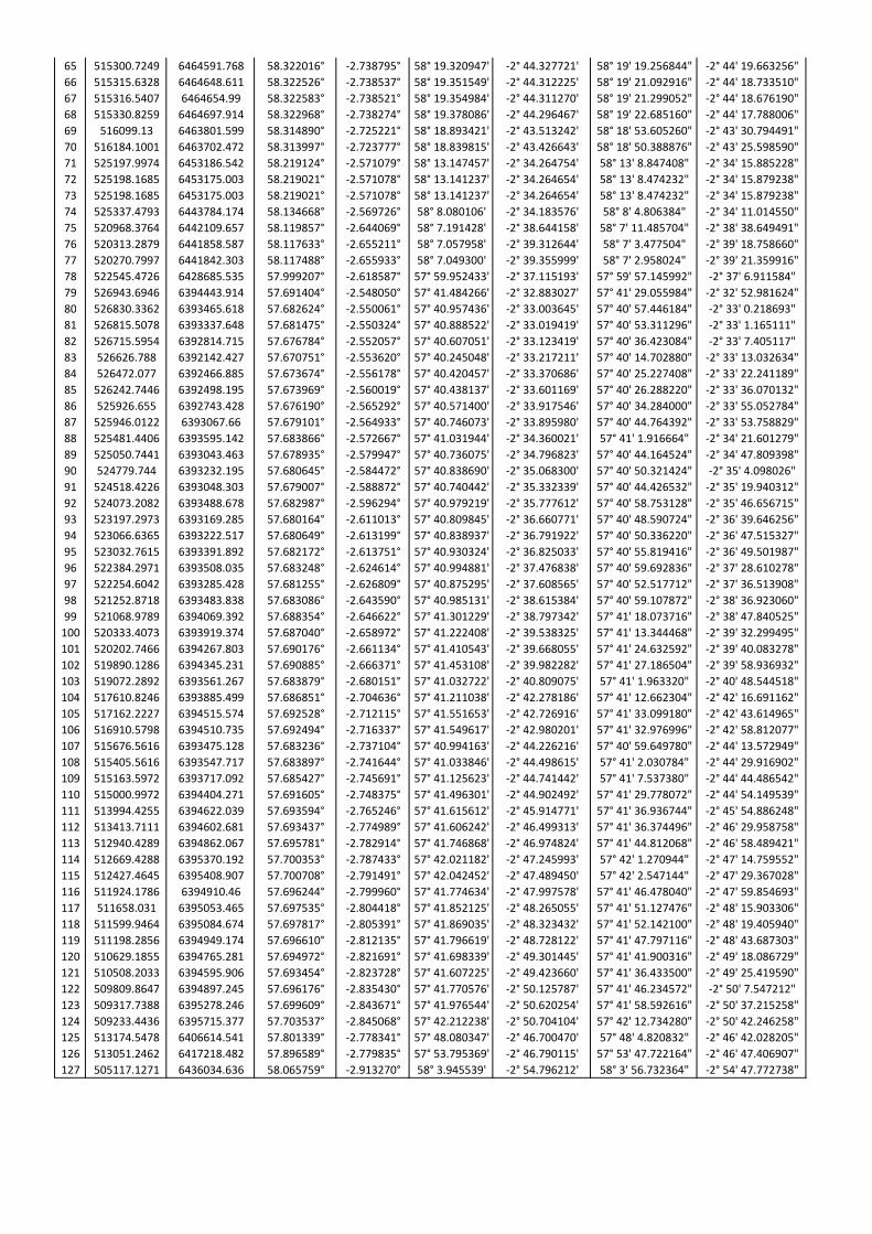
65 515300.7249 6464591.768 58.322016° -2.738795° 58° 19.320947' -2° 44.327721' 58° 19' 19.256844" -2° 44' 19.663256"
66 515315.6328 6464648.611 58.322526° -2.738537° 58° 19.351549' -2° 44.312225' 58° 19' 21.092916" -2° 44' 18.733510"
67 515316.5407 6464654.99 58.322583° -2.738521° 58° 19.354984' -2° 44.311270' 58° 19' 21.299052" -2° 44' 18.676190"
68 515330.8259 6464697.914 58.322968° -2.738274° 58° 19.378086' -2° 44.296467' 58° 19' 22.685160" -2° 44' 17.788006"
69 516099.13 6463801.599 58.314890° -2.725221° 58° 18.893421' -2° 43.513242' 58° 18' 53.605260" -2° 43' 30.794491"
70 516184.1001 6463702.472 58.313997° -2.723777° 58° 18.839815' -2° 43.426643' 58° 18' 50.388876" -2° 43' 25.598590"
71 525197.9974 6453186.542 58.219124° -2.571079° 58° 13.147457' -2° 34.264754' 58° 13' 8.847408" -2° 34' 15.885228"
72 525198.1685 6453175.003 58.219021° -2.571078° 58° 13.141237' -2° 34.264654' 58° 13' 8.474232" -2° 34' 15.879238"
73 525198.1685 6453175.003 58.219021° -2.571078° 58° 13.141237' -2° 34.264654' 58° 13' 8.474232" -2° 34' 15.879238"
74 525337.4793 6443784.174 58.134668° -2.569726° 58° 8.080106' -2° 34.183576' 58° 8' 4.806384" -2° 34' 11.014550"
75 520968.3764 6442109.657 58.119857° -2.644069° 58° 7.191428' -2° 38.644158' 58° 7' 11.485704" -2° 38' 38.649491"
76 520313.2879 6441858.587 58.117633° -2.655211° 58° 7.057958' -2° 39.312644' 58° 7' 3.477504" -2° 39' 18.758660"
77 520270.7997 6441842.303 58.117488° -2.655933° 58° 7.049300' -2° 39.355999' 58° 7' 2.958024" -2° 39' 21.359916"
78 522545.4726 6428685.535 57.999207° -2.618587° 57° 59.952433' -2° 37.115193' 57° 59' 57.145992" -2° 37' 6.911584"
79 526943.6946 6394443.914 57.691404° -2.548050° 57° 41.484266' -2° 32.883027' 57° 41' 29.055984" -2° 32' 52.981624"
80 526830.3362 6393465.618 57.682624° -2.550061° 57° 40.957436' -2° 33.003645' 57° 40' 57.446184" -2° 33' 0.218693"
81 526815.5078 6393337.648 57.681475° -2.550324° 57° 40.888522' -2° 33.019419' 57° 40' 53.311296" -2° 33' 1.165111"
82 526715.5954 6392814.715 57.676784° -2.552057° 57° 40.607051' -2° 33.123419' 57° 40' 36.423084" -2° 33' 7.405117"
83 526626.788 6392142.427 57.670751° -2.553620° 57° 40.245048' -2° 33.217211' 57° 40' 14.702880" -2° 33' 13.032634"
84 526472.077 6392466.885 57.673674° -2.556178° 57° 40.420457' -2° 33.370686' 57° 40' 25.227408" -2° 33' 22.241189"
85 526242.7446 6392498.195 57.673969° -2.560019° 57° 40.438137' -2° 33.601169' 57° 40' 26.288220" -2° 33' 36.070132"
86 525926.655 6392743.428 57.676190° -2.565292° 57° 40.571400' -2° 33.917546' 57° 40' 34.284000" -2° 33' 55.052784"
87 525946.0122 6393067.66 57.679101° -2.564933° 57° 40.746073' -2° 33.895980' 57° 40' 44.764392" -2° 33' 53.758829"
88 525481.4406 6393595.142 57.683866° -2.572667° 57° 41.031944' -2° 34.360021' 57° 41' 1.916664" -2° 34' 21.601279"
89 525050.7441 6393043.463 57.678935° -2.579947° 57° 40.736075' -2° 34.796823' 57° 40' 44.164524" -2° 34' 47.809398"
90 524779.744 6393232.195 57.680645° -2.584472° 57° 40.838690' -2° 35.068300' 57° 40' 50.321424" -2° 35' 4.098026"
91 524518.4226 6393048.303 57.679007° -2.588872° 57° 40.740442' -2° 35.332339' 57° 40' 44.426532" -2° 35' 19.940312"
92 524073.2082 6393488.678 57.682987° -2.596294° 57° 40.979219' -2° 35.777612' 57° 40' 58.753128" -2° 35' 46.656715"
93 523197.2973 6393169.285 57.680164° -2.611013° 57° 40.809845' -2° 36.660771' 57° 40' 48.590724" -2° 36' 39.646256"
94 523066.6365 6393222.517 57.680649° -2.613199° 57° 40.838937' -2° 36.791922' 57° 40' 50.336220" -2° 36' 47.515327"
95 523032.7615 6393391.892 57.682172° -2.613751° 57° 40.930324' -2° 36.825033' 57° 40' 55.819416" -2° 36' 49.501987"
96 522384.2971 6393508.035 57.683248° -2.624614° 57° 40.994881' -2° 37.476838' 57° 40' 59.692836" -2° 37' 28.610278"
97 522254.6042 6393285.428 57.681255° -2.626809° 57° 40.875295' -2° 37.608565' 57° 40' 52.517712" -2° 37' 36.513908"
98 521252.8718 6393483.838 57.683086° -2.643590° 57° 40.985131' -2° 38.615384' 57° 40' 59.107872" -2° 38' 36.923060"
99 521068.9789 6394069.392 57.688354° -2.646622° 57° 41.301229' -2° 38.797342' 57° 41' 18.073716" -2° 38' 47.840525"
100 520333.4073 6393919.374 57.687040° -2.658972° 57° 41.222408' -2° 39.538325' 57° 41' 13.344468" -2° 39' 32.299495"
101 520202.7466 6394267.803 57.690176° -2.661134° 57° 41.410543' -2° 39.668055' 57° 41' 24.632592" -2° 39' 40.083278"
102 519890.1286 6394345.231 57.690885° -2.666371° 57° 41.453108' -2° 39.982282' 57° 41' 27.186504" -2° 39' 58.936932"
103 519072.2892 6393561.267 57.683879° -2.680151° 57° 41.032722' -2° 40.809075' 57° 41' 1.963320" -2° 40' 48.544518"
104 517610.8246 6393885.499 57.686851° -2.704636° 57° 41.211038' -2° 42.278186' 57° 41' 12.662304" -2° 42' 16.691162"
105 517162.2227 6394515.574 57.692528° -2.712115° 57° 41.551653' -2° 42.726916' 57° 41' 33.099180" -2° 42' 43.614965"
106 516910.5798 6394510.735 57.692494° -2.716337° 57° 41.549617' -2° 42.980201' 57° 41' 32.976996" -2° 42' 58.812077"
107 515676.5616 6393475.128 57.683236° -2.737104° 57° 40.994163' -2° 44.226216' 57° 40' 59.649780" -2° 44' 13.572949"
108 515405.5616 6393547.717 57.683897° -2.741644° 57° 41.033846' -2° 44.498615' 57° 41' 2.030784" -2° 44' 29.916902"
109 515163.5972 6393717.092 57.685427° -2.745691° 57° 41.125623' -2° 44.741442' 57° 41' 7.537380" -2° 44' 44.486542"
110 515000.9972 6394404.271 57.691605° -2.748375° 57° 41.496301' -2° 44.902492' 57° 41' 29.778072" -2° 44' 54.149539"
111 513994.4255 6394622.039 57.693594° -2.765246° 57° 41.615612' -2° 45.914771' 57° 41' 36.936744" -2° 45' 54.886248"
112 513413.7111 6394602.681 57.693437° -2.774989° 57° 41.606242' -2° 46.499313' 57° 41' 36.374496" -2° 46' 29.958758"
113 512940.4289 6394862.067 57.695781° -2.782914° 57° 41.746868' -2° 46.974824' 57° 41' 44.812068" -2° 46' 58.489421"
114 512669.4288 6395370.192 57.700353° -2.787433° 57° 42.021182' -2° 47.245993' 57° 42' 1.270944" -2° 47' 14.759552"
115 512427.4645 6395408.907 57.700708° -2.791491° 57° 42.042452' -2° 47.489450' 57° 42' 2.547144" -2° 47' 29.367028"
116 511924.1786 6394910.46 57.696244° -2.799960° 57° 41.774634' -2° 47.997578' 57° 41' 46.478040" -2° 47' 59.854693"
117 511658.031 6395053.465 57.697535° -2.804418° 57° 41.852125' -2° 48.265055' 57° 41' 51.127476" -2° 48' 15.903306"
118 511599.9464 6395084.674 57.697817° -2.805391° 57° 41.869035' -2° 48.323432' 57° 41' 52.142100" -2° 48' 19.405940"
119 511198.2856 6394949.174 57.696610° -2.812135° 57° 41.796619' -2° 48.728122' 57° 41' 47.797116" -2° 48' 43.687303"
120 510629.1855 6394765.281 57.694972° -2.821691° 57° 41.698339' -2° 49.301445' 57° 41' 41.900316" -2° 49' 18.086729"
121 510508.2033 6394595.906 57.693454° -2.823728° 57° 41.607225' -2° 49.423660' 57° 41' 36.433500" -2° 49' 25.419590"
122 509809.8647 6394897.245 57.696176° -2.835430° 57° 41.770576' -2° 50.125787' 57° 41' 46.234572" -2° 50' 7.547212"
123 509317.7388 6395278.246 57.699609° -2.843671° 57° 41.976544' -2° 50.620254' 57° 41' 58.592616" -2° 50' 37.215258"
124 509233.4436 6395715.377 57.703537° -2.845068° 57° 42.212238' -2° 50.704104' 57° 42' 12.734280" -2° 50' 42.246258"
125 513174.5478 6406614.541 57.801339° -2.778341° 57° 48.080347' -2° 46.700470' 57° 48' 4.820832" -2° 46' 42.028205"
126 513051.2462 6417218.482 57.896589° -2.779835° 57° 53.795369' -2° 46.790115' 57° 53' 47.722164" -2° 46' 47.406907"
127 505117.1271 6436034.636 58.065759° -2.913270° 58° 3.945539' -2° 54.796212' 58° 3' 56.732364" -2° 54' 47.772738"