
MKIV_20system_20description
15
Elektronikon MKIV System Description _________________________________________________________________________________________________ H:/MAGUIRE/MKIV 1 1 General description The Elektronikon MKIV regulator is the heart of most regulation systems used on Atlas Copco stationary compressors. The Elektronikon regulator is an advanced electronic control and monitoring system specifically designed to operate Atlas Copco stationary air compressors. On fixed speed machines the MKIV regulator maintains the compressed air net pressure between the programmed load and unload pressure settings by loading, unloading, starting or stopping the compressor automatically. The regulator uses an advanced control algorithm called DSS, delayed second stop, to minimize the power consumption of the compressor by only running the drive motor when absolutely necessary. This function also minimizes the number of motor starts to insure a long motor service life. On variable speed drive machines, VSDs, the MKIV regulator continuously compares the net pressure to the operator selected programmed setpoint pressure. The MKIV regulator then sends a control signal to the variable speed drive to adjust the compressor speed to either produce more air, if the net pressure is falling, or to produce less air if the net pressure is rising. The regulator also protects the compressor. It continuously monitors critical parameters of the compressor and shuts the unit down in the event of a problem. It acts as an operator interface allowing an operator access to the information monitored by the regulator through an efficiently laid out menu screen. Service parameters are also monitored and an operator is notified when service is required so that maintenance can be scheduled to suit the plant’s production needs. 2 Elektronikon MKIV Hardware The MKIV is the latest generation of the Elektronikon regulator. The MKIV consists of three basic master module hardware platforms, Elektronikon I, Elektronikon II and Elektronikon III. The configurations of which type regulator is used on which compressor model along with input and output, I/O, details are given in table one at the end of this document. 2.1 Elektronikon MKIV-I Elektronikon MKIV-I regulator is a very simple regulator used by smaller compressors that don’t have a lot of I/O requirements. It has a symbol based back lit LCD, liquid crystal display, and is intended to be an electronic replacement for simple electropneumatic control. The MKIV-I regulator has one pressure input, discharge pressure, and two temperature inputs, element outlet and LAT for FF units. The MKIV-I regulator has three digital inputs, emergency stop, motor overload and remote start/stop. The MKIV-I regulator has six digital outputs, star contactor, line contactor, delta contactor, load/unload solenoid valve, general shutdown and dryer control. The MKIV-I requires no programming on commissioning a simple process of parameter selection done at the faceplate of the regulator selecting which compressor is being controlled is all that is required. The regulator has no serial communication or expansion capabilities. The basic operational features that are not available with the MKIV-I that are available with the other regulators are no clock based control function, only one pressure set selection is possible and no sequencer control is possible. 2.2 Elektronikon MKIV-II The Elektronikon MKIV-II regulator has a lot more features than the type I regulator and is intended to be used on larger compressors that have greater I/O and communication requirements. It has a 4x16 character back lit LCD and is alpha numeric. The type II regulator has two hardware sub platforms, the version A and the version B regulators. The basic functionality is the same between the two regulators the only difference is in the number of I/O and the communication ports that are available. The type II and the type I regulators are physically the same size.
-
Upload
shailesh-kshatriya -
Category
Documents
-
view
135 -
download
7
description
Atlas copco compressor/dryer controller
Transcript of MKIV_20system_20description

Elektronikon MKIV System Description_________________________________________________________________________________________________
H:/MAGUIRE/MKIV 1
1 General description
The Elektronikon MKIV regulator is the heart of most regulation systems used on Atlas Copco stationarycompressors. The Elektronikon regulator is an advanced electronic control and monitoring system specificallydesigned to operate Atlas Copco stationary air compressors.
On fixed speed machines the MKIV regulator maintains the compressed air net pressure between theprogrammed load and unload pressure settings by loading, unloading, starting or stopping the compressorautomatically. The regulator uses an advanced control algorithm called DSS, delayed second stop, tominimize the power consumption of the compressor by only running the drive motor when absolutelynecessary. This function also minimizes the number of motor starts to insure a long motor service life.
On variable speed drive machines, VSDs, the MKIV regulator continuously compares the net pressure to theoperator selected programmed setpoint pressure. The MKIV regulator then sends a control signal to thevariable speed drive to adjust the compressor speed to either produce more air, if the net pressure is falling, orto produce less air if the net pressure is rising.
The regulator also protects the compressor. It continuously monitors critical parameters of the compressor andshuts the unit down in the event of a problem. It acts as an operator interface allowing an operator access tothe information monitored by the regulator through an efficiently laid out menu screen. Service parameters arealso monitored and an operator is notified when service is required so that maintenance can be scheduled tosuit the plant’s production needs.
2 Elektronikon MKIV Hardware
The MKIV is the latest generation of the Elektronikon regulator. The MKIV consists of three basic mastermodule hardware platforms, Elektronikon I, Elektronikon II and Elektronikon III.
The configurations of which type regulator is used on which compressor model along with input and output,I/O, details are given in table one at the end of this document.
2.1 Elektronikon MKIV-I
Elektronikon MKIV-I regulator is a very simple regulator used by smaller compressors that don’t have a lot ofI/O requirements. It has a symbol based back lit LCD, liquid crystal display, and is intended to be an electronicreplacement for simple electropneumatic control.
The MKIV-I regulator has one pressure input, discharge pressure, and two temperature inputs, element outletand LAT for FF units. The MKIV-I regulator has three digital inputs, emergency stop, motor overload andremote start/stop. The MKIV-I regulator has six digital outputs, star contactor, line contactor, delta contactor,load/unload solenoid valve, general shutdown and dryer control. The MKIV-I requires no programming oncommissioning a simple process of parameter selection done at the faceplate of the regulator selecting whichcompressor is being controlled is all that is required. The regulator has no serial communication or expansioncapabilities. The basic operational features that are not available with the MKIV-I that are available with theother regulators are no clock based control function, only one pressure set selection is possible and nosequencer control is possible.
2.2 Elektronikon MKIV-II
The Elektronikon MKIV-II regulator has a lot more features than the type I regulator and is intended to beused on larger compressors that have greater I/O and communication requirements. It has a 4x16 characterback lit LCD and is alpha numeric. The type II regulator has two hardware sub platforms, the version A and theversion B regulators. The basic functionality is the same between the two regulators the only difference is inthe number of I/O and the communication ports that are available. The type II and the type I regulators arephysically the same size.

Elektronikon MKIV System Description_________________________________________________________________________________________________
H:/MAGUIRE/MKIV 2
The version A regulator has one pressure input, two temperature inputs, eight digital inputs, nine digitaloutputs, a CAN port and an expansion port. The version B regulator has two pressure inputs, threetemperature inputs, ten digital inputs, nine digital outputs, an RS485 port (for communication between theElektronikon and the drive on VSD units), a CAN port and an expansion port.
The type II regulators have very flexible communication and expansion capabilities that are detailed later on inthis document.
2.3 Elektronikon MKIV-III
The Elektronikon MKIV-III regulator, like the type II, has a lot more features than the type I regulator and isintended to be used on larger compressors that have greater I/O and communication requirements. It has a4x40 character back lit LCD and is alpha numeric. The type III regulator has two hardware sub platforms, theversion C and the version D regulators. The basic functionality is the same between the two controllers theonly difference is in the number of I/O and the communication ports that are available. The type III is physicallylarger than the type I and II regulators.
The version C regulator has four pressure inputs, eight temperature inputs, ten digital inputs, nine digitaloutputs, a CAN port and an expansion port. The version D regulator has four pressure inputs, ten temperatureinputs, ten digital inputs, nine digital outputs, an RS485 port (for communication between the Elektronikon
and the drive on VSD units), a CAN port and an expansion port.
The type III regulators have very flexible communication and expansion capabilities that are detailed later on inthis document.
2.4 What’s new with the MKIV
The new Elektronikon MKIV is the latest generation in compressor regulation technology from Atlas Copco.As the Elektronikon has evolved over the years each new generation has built on the experience of theprevious generation culminating in the features that make up the MKIV regulator. The new MKIV regulator hasall of the functionality of the MKIII plus some new features that make it an improved version. The MKIV has thesame stringent hardware specifications as the MKIII from an environmental and electrical standpoint.
Many of the distinguishing characteristics that differentiate the MKIV from its immediate predecessor the MKIIIare outlined below.
2.4.1 Technology
The MKIV platform is based on today’s latest microprocessor technology. The hardware is more robust thanthe previous versions. For example the terminal connections where the wiring is connected to the MKIV arechanged to WAGO “spring type” connections that are an improvement over the version used previously. Thesenew terminal connections are more resistant to becoming “loose” over time, and making connections is a loteasier.
The internal operating system software has been changed to a PLC based system that is widely used in themicroprocessor industry. The application software is written in a well known and flexible software that is basedon the IEC standard IEC 1131. These improvements make programming changes much simpler and shouldallow the MKIV system to be more flexible to unique applications. This flexibility will allow the MKIV system totake on more responsibility for control and monitoring of not only the air compressor but also other pieces ofequipment that one normally finds in a compressor room.
The MKIV has more I/O and as a consequence most of the standard machine configurations that use theregulator do not require expansion modules which reduces the number of components required in a MKIVsystem over the MKIII.

Elektronikon MKIV System Description_________________________________________________________________________________________________
H:/MAGUIRE/MKIV 3
The liquid crystal display, LCD, that is used as the operator interface has been improved. The previous versionused a black screen with green characters. The new display uses a green screen with black characters andthe backlighting of the display has been improved. These two features not only improve the viewing angle ofthe display but make it easier to read in direct sunlight than the previous version.
The basic operation of the MKIV is the same as the MKIII, with many additional features, so theoretically theMKIV can be used to replace the MKIII on any compressor with some work to be done locally. The major itemsto be considered would be the door panel. The physical size of the MKIV is not the same as the MKIII so thecut out in the cubicle door of the MKIII is not suitable to accept the MKIV. Wiring harness. At the very least theterminal plugs would need to be changed so that the wiring harness would be accepted with the MKIVregulator. The sensors and digital I/O are the same for most compressor variants. Decisions for replacementsuitability should be made on a case by case basis for the each application being considered.
2.4.2 Features
The MKIV has many new features built in that make it a significant improvement over the previous generationsof regulators.
All of the regulator types now have digital output auxiliary relays as standard. With the MKIII LRR a relayexpansion module would need to be added. With the MKIV family all of the regulator types have at least oneauxiliary relay output. Refer to section 2 detailing I/O of each regulator type.
The look and feel of the menus screens has been improved with a more logical ordering of the informationavailable to make scrolling for information easier than with the MKIII. For example all screens indicate with anarrow if more information is contained in a section or if only a warning is present then the warning messagewill blink.
Two pressure sets or pressure bands can be programmed called pressure band 1 and pressure band 2.Different loading and unloading set points can be programmed in so that two distinct pressure bands can beused in the process. These two bands can be selected either manually at the faceplate of the regulator or canbe programmed to change at a certain time. This feature is not available for the MKIV-I regulator.
Control mode selection is down at the display instead of using digital inputs to the master module as was donewith the MKIII. Refer to section 4 for more information on the different control modes that are available.
A more comprehensive set of expansion modules is available with no expansion module programmingrequired. Refer to section 3.1 for more information on the expansion capability of the MKIV system.
A separate communication module is no longer required for local area networking or VSD communication. TheMKIV-II and III have versions which include LAN and RS485 ports as standard built right into the module.
Programming of the modules has been greatly improved. The programming of the modules is done over theCAN port, see communication section 3.2 for CAN details. Separate language, setting and expansion modulefiles are no longer required only one file per division is required. The Field Download Program, FDP, isavailable on the LN software market. The necessary file one needs to program a regulator for an application isavailable on a LN database dedicated for these files. Language and machine specific selection is done withthe FDP and programming of the master module over the CAN is all that is required. The Service DiagnosticPackage, SDP, remains to be used for the purposes that it was used for in the past such as programmingspecial input functions. The MKIV-I regulator requires no programming at all. A simple process calledparameter set selection is done at the faceplate of the regulator at commissioning to select the machineparameters.
A help screen has been added so that a local contact can be added to the module that gives the customer thelocal contact information. By default the Atlas Copco web site address is featured but this can be modifiedlocally.

Elektronikon MKIV System Description_________________________________________________________________________________________________
H:/MAGUIRE/MKIV 4
Service notification has been simplified. Instead of individual service alarms a series of service plans havebeen developed. Each service plan has a set of service actions that are detailed in the instruction book of themachine. Two general counters are monitored by the MKIV, a running hours counter and a real time counter.When one of the counters equals a multiple of the service interval detailed in the service plan a servicewarning is generated. The corresponding service plan is displayed, i.e. Service Plan A, B, C etc. Individuallymonitored components, for example Oil Separator differential pressure, may indicate that service is requiredprior to the expiration of a service plan time interval. In cases like this an operator will be notified for the needto service the individual component in question prior to the elapse of a service counter.
Multiple Compressor Control, MCC. When activated this feature allows one of the compressors in aninstallation, up to four maximum, to act as a master compressor controller or sequencer. The MCC feature isdescribed in more detail in section 4.3.2.
3 Optional accessories
The MKIV system is very flexible and complete. The standard options that are available to compliment theMKIV system are described in detail below. The accessories described below are not available on the MKIV-Iregulator. The MKIV system can handle up to a maximum of eight modules in one system. For example onemaster module plus up to a maximum of seven expansion or communication modules per compressor.
These accessories can be found on the Lotus Notes database under Options and accessories for theElektronikon MKIV.
3.1 Expansion modules
One of the many new features of the MKIV system is that the expansion modules are now installed on theback plate of the compressor control cubicle and are DIN rail mounted. Most of the expansion modules requireonly a cable connection that connects it into the Elektronikon system with no power connections required.Two standard prefabricated cables are available and are listed on the options list in LN.
3.1.1 AIE1
The analogue input expansion module number 1, AIE1, has two inputs for the standard Kavlico pressuretransducers and two inputs for the standard Jumo PT1000 temperature resistance temperature detectors,RTDs, used on Atlas Copco compressors.
This expansion module could be used if additional temperature or pressure points need to be measured.
What is required is the installation of the sensor into the compressor package where appropriate. Run asensor cable from the sensor to the compressor control cubicle. Mount the AIE1 onto the DIN rail of thecompressor cubicle back plate, connect the AIE1 into the Elektronikon system using a prefabricated cablelisted on the options list. Then finally program the regulator using the FDP or SDP program to accept the inputand its intended function.
3.1.2 AIE2
The analogue input expansion module number 2, AIE2, has four inputs for 4-20 mA analogue inputs. This expansion module could be used if additional 4-20 mA inputs need to be measured.
What is required is the installation of the sensor into the compressor package where appropriate. Run asensor cable from the sensor to the compressor control cubicle. Mount the AIE2 onto the DIN rail of thecompressor cubicle back plate, connect the AIE2 into the Elektronikon system using a prefabricated cablelisted on the options list. Install a separate 24VDC power supply into the cubicle and wire this power supply tothe module, we recommend ps 1089045773 which is an Omron S82K-00324 100-240VAC to 24 VDC, 3 W.

Elektronikon MKIV System Description_________________________________________________________________________________________________
H:/MAGUIRE/MKIV 5
Then finally program the regulator using the FDP or SDP program to accept the input and its intendedfunction.
3.1.3 AIE3
The analogue input expansion module number 3, AIE3, has five inputs for PT 100 temperature RTDs.
This expansion module could be used if additional temperature points are needed and the RTD is a PT 100style.
What is required is the installation of the sensor into the compressor package where appropriate. Run asensor cable from the sensor to the compressor control cubicle. Mount the AIE3 onto the DIN rail of thecompressor cubicle back plate, connect the AIE3 into the Elektronikon system using a prefabricated cablelisted on the options list. Then finally program the regulator using the FDP or SDP program to accept the inputand its intended function.
3.1.4 AIE4
The analogue input expansion module number 4, AIE4, has five inputs for PT1000 temperature RTDs.
This expansion module could be used if additional temperature points are needed and the RTD is a PT1000style.
What is required is the installation of the sensor into the compressor package where appropriate. Run asensor cable from the sensor to the compressor control cubicle. Mount the AIE4 onto the DIN rail of thecompressor cubicle back plate, connect the AIE4 into the Elektronikon system using a prefabricated cablelisted on the options list. Then finally program the regulator using the FDP or SDP program to accept the inputand its intended function.
3.1.5 DIOE
The digital input/output expansion module, DIOE, allows the addition of up to two digital I/O to be incorporatedinto the MKIV system.
This expansion module would be used if a user wanted to add extra digital inputs to a compressor. Forexample if a customer wanted to indicate a high filter differential pressure on a set of pre-filters that wereadded to the compressor in the field. One would connect the auxiliary contact from the dp switch to the DIOEinput.
What is required is the installation of the sensor into the compressor package where appropriate. Wire thecontacts, they must be voltage free, from the indicator to the control cubicle. Mount the DIOE onto the DIN railof the compressor cubicle back plate, connect the DIOE into the Elektronikon system using a prefabricatedcable listed on the options list. Then finally program the regulator using the FDP or SDP program to accept theinput and its intended function.
3.2 Communication modules
A series of communication modules have been developed that allow the MKIV system to be connected to ausers plant wide communication network. These modules, ComBox-yy, convert the CAN protocol used by theElektronikon into the communication protocol used by the installation.
The Elektronikon MKIV regulators, not MKIV-I, all have a field bus port built in as standard. The fieldbus usedby the MKIV is called CAN. CAN, Controller Area Network, is an ISO approved standard communicationprotocol that was developed in 1984 by Bosch for in vehicle data transmission. It is a very robust and wellknown standard that is extremely reliable and fault tolerant.
Elektronikon MKIV System Description_________________________________________________________________________________________________
H:/MAGUIRE/MKIV 6
3.2.1 ComBox-Modbus
The ComBox-Modbus converts the CAN protocol used by the Elektronikon into the Modbus RTU protocol.The ComBox allows a compressor(s) to be connected to a customer’s Modbus network. The customer canthen monitor all of the mission critical parameters of the compressor(s) and do some light control over hisnetwork using his plant’s DCS.
The ComBox can be installed in any one of the compressors in a network. The unique feature of the MKIVCAN network is that only one ComBox is required for an installation. Please refer to section 4.3 under LAN formore information.
The ComBox-Modbus needs to be programmed in the field at commissioning by an Atlas Copco ServiceEngineer.
Please refer to the ComBox Modbus instruction manual for more details.
3.2.2 ComBox-Profibus
The ComBox-Profibus converts the CAN protocol used by the Elektronikon into the Profibus protocol. TheComBox allows a compressor(s) to be connected to a customer’s Profibus network. The customer can thenmonitor all of the mission critical parameters of the compressor(s) and do some light control over his networkusing his plant’s DCS.
The ComBox can be installed in any one of the compressors in a network. The unique feature of the MKIVCAN network is that only one ComBox is required for an installation. Please refer to section 4.3 under LAN formore information.
The ComBox-Profibus needs to be programmed in the field at commissioning by an Atlas Copco ServiceEngineer.
Please refer to the ComBox Profibus instruction manual for more details.
3.2.3 ComBox-Ethernet
The ComBox-Ethernet converts the CAN protocol used by the Elektronikon into the Ethernet protocol. TheComBox allows a compressor(s) to be connected to a customer’s Ethernet network. The customer can thenmonitor all of the mission critical parameters of the compressor(s) and do some light control over his networkusing his plant’s DCS.
The ComBox can be installed in any one of the compressors in a network. The unique feature of the MKIVCAN network is that only one ComBox is required for an installation. Please refer to section 4.3 under LAN formore information.
The ComBox- Ethernet needs to be programmed in the field at commissioning by an Atlas Copco ServiceEngineer.
Please refer to the ComBox Ethernet instruction manual for more details.
3.2.4 ComBox-RS232
Many occasions will arise when one will need to add an older version Elektronikon machine to the MKIVCAN. This could include not only a compressor with an older generation Elektronikon but also an ESsequencer. The ComBox-RS232 can be installed on an older version Elektronikon machine, that has anRS232 port, to convert the RS232 Elektronikon protocol to the CAN protocol.
Elektronikon MKIV System Description_________________________________________________________________________________________________
H:/MAGUIRE/MKIV 7
The ComBox-RS232 is installed on the compressor back plate of the compressor that needs the conversion.The RS232 ports of the ComBox and the Elektronikon are connected using cables and connectors suppliedby others. Then the machine can be connected into the CAN network according to the standard networkingconnection procedures developed for the MKIV CAN system. A separate instruction is available for CANwiring, 9820358200.
3.2.5 ComBox-DIOE
Many occasions will arise when a non Elektronikon machine would need to be added to the MKIV CANsystem. This could be an electro-pneumatic regulated compressor, a MKIII LRR or a competitor’s compressorthat can be controlled remotely using digital control.
The ComBox-DIOE is similar to the ES001 product. The ComBox-DIOE will convert the signals to and from thedigitally controlled compressor to the CAN.
The ComBox-DIOE is a product that is contained in its own enclosure. It would need to be installed near thecompressor being converted to the CAN. The ComBox-DIOE requires its own single phase power supply,220/120VAC; 50/60Hz.
3.2.6 e-Box I
The e-Box I is a device that allows a user to monitor a compressor installation over the internet or his ownethernet network.
The e-Box I can be connected to a MKIV CAN compressor network, up to four compressors maximum. TheWeb application software is embedded into the e-Box I. No controlling of the compressor network is possible.The web application software will allow a user to dial up the web address of the installation and then monitoreach compressor attached to the network. The user will be able to see all of the monitoring points of theElektronikon as well as the current status of each compressor. A user could schedule data dumps into his owndatabase and then could trend data for maintenance purposes. The e-Box I will store data for the last 24 hoursof operation. During set up of the system a user can designate three user profiles to receive automatic e-mailmessages in the event of a general shutdown, general warning or service warning. In the event of a shutdownthe e-Box I will store all data and compressor status for review.
The e-Box I can be installed in one of the compressors and then networked to the others using the CAN. Thee-Box I will require either a modem or a router to connect to the internet that is supplied by others. The e-BoxI requires its own single phase power supply, 220/120VAC; 50/60Hz.
See the separate e-Box I instruction manual for more details.
3.2.7 e-Box II
The e-Box II is a device that allows a compressed air installation to take advantage of the e-Services offeredby Atlas Copco over the internet.
The e-Box II can be installed in an installation and up to four compressors can be connected over the internetto Atlas Copco’s web site and its series of web applications. Depending on the needs of the customer severaldifferent levels of service can be offered from simple monitoring of the compressed air installation over theweb to full service responsibility of the installation with close interaction to the local Atlas Copcorepresentative.
The e-Box II can be installed in one of the compressors and then networked to the others using the CAN. Thee-Box II will require either a modem or a router to connect to the internet that is supplied by others. The e-BoxII requires its own single phase power supply, 220/120VAC; 50/60Hz.
See the separate e-Box II instruction manual for more details.

Elektronikon MKIV System Description_________________________________________________________________________________________________
H:/MAGUIRE/MKIV 8
4 Control modes
The Elektronikon MKIV regulator has three distinct modes of compressor control, CCM. The compressor canbe controlled locally, remotely or via a local area network (LAN).
Each control mode is mutually exclusive meaning if the regulator is under one control mode it can not becontrolled by another at the same time. This limitation is built in for safeguarding not only the compressor butalso operating personnel.
The control modes are switched manually through the faceplate of the Elektronikon by an operator. This is adifferent feature for the MKIV. The MKIII was switched by manipulating digital inputs of the master module byeither terminal switches, LRR, or by the use of a key switch located on the cubicle door, HRR.
The examples that follow are primarily for the type II and III regulators. Switching between local and remotecontrol is also done through the regulator faceplate on the MKIV-I regulator parameter number 009.
4.1 Local control mode
When the compressor regulator is in local control mode the regulator will indicate this by displaying thefollowing screen:
CCM ↑Local control
Menu Mod ↓F1 F2 F3
The compressor control mode, CCM, is displayed in the Configuration subsection of the Modify settingssection.
When the CCM is set for local the compressor can only be controlled locally or at the Elektronikon faceplateby an operator. This would normally mean the starting, stopping, loading or unloading of the compressor by anoperator through the faceplate of the Elektronikon. In local control the compressor will acknowledge andexecute a remote emergency stop command. The loading and unloading command can also be excuted by anexternal pressure sensing device, such as a pressure switch or ES100, if “remote pressure sensing” input tothe Elektronikon is bridged. See figure six as an example. In this situation the normal loading and unloadingof the pressure band programmed into the regulator is ignored and the regulator looks at the status of theremote load/unload input. The compressor will load if this input is closed and unload if this input is open. TheElektronikon DSS function is disabled when remote pressure sensing is active and the motor idling time is afunction of the number of motor starts per hour that is programmed into the regulator. This remote pressuresensing feature is not included with the Elektronikon MKIV-I regulator.
Any digital input wired into the Elektronikon must be a voltage free contact.
Elektronikon MKIV System Description_________________________________________________________________________________________________
H:/MAGUIRE/MKIV 9
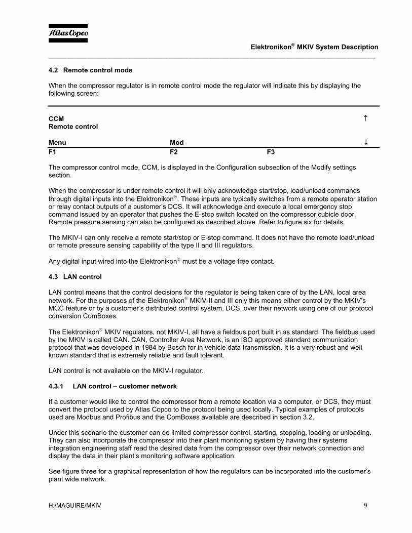
4.2 Remote control mode
When the compressor regulator is in remote control mode the regulator will indicate this by displaying thefollowing screen:
CCM ↑Remote control
Menu Mod ↓F1 F2 F3
The compressor control mode, CCM, is displayed in the Configuration subsection of the Modify settingssection.
When the compressor is under remote control it will only acknowledge start/stop, load/unload commandsthrough digital inputs into the Elektronikon. These inputs are typically switches from a remote operator stationor relay contact outputs of a customer’s DCS. It will acknowledge and execute a local emergency stopcommand issued by an operator that pushes the E-stop switch located on the compressor cubicle door.Remote pressure sensing can also be configured as described above. Refer to figure six for details.
The MKIV-I can only receive a remote start/stop or E-stop command. It does not have the remote load/unloador remote pressure sensing capability of the type II and III regulators.
Any digital input wired into the Elektronikon must be a voltage free contact.
4.3 LAN control
LAN control means that the control decisions for the regulator is being taken care of by the LAN, local areanetwork. For the purposes of the Elektronikon MKIV-II and III only this means either control by the MKIV’sMCC feature or by a customer’s distributed control system, DCS, over their network using one of our protocolconversion ComBoxes.
The Elektronikon MKIV regulators, not MKIV-I, all have a fieldbus port built in as standard. The fieldbus usedby the MKIV is called CAN. CAN, Controller Area Network, is an ISO approved standard communicationprotocol that was developed in 1984 by Bosch for in vehicle data transmission. It is a very robust and wellknown standard that is extremely reliable and fault tolerant.
LAN control is not available on the MKIV-I regulator.
4.3.1 LAN control – customer network
If a customer would like to control the compressor from a remote location via a computer, or DCS, they mustconvert the protocol used by Atlas Copco to the protocol being used locally. Typical examples of protocolsused are Modbus and Profibus and the ComBoxes available are described in section 3.2.
Under this scenario the customer can do limited compressor control, starting, stopping, loading or unloading.They can also incorporate the compressor into their plant monitoring system by having their systemsintegration engineering staff read the desired data from the compressor over their network connection anddisplay the data in their plant’s monitoring software application.
See figure three for a graphical representation of how the regulators can be incorporated into the customer’splant wide network.

Elektronikon MKIV System Description_________________________________________________________________________________________________
H:/MAGUIRE/MKIV 10
Networking of Atlas Copco compressors can be done with any generation of Elektronikon orelectropneumatic regulated compressor. To make it simple all connected compressors must be brought somehow over to the CAN. A series of ComBoxes has been developed to do this please refer to section 3.2. Adetailed document has been prepared by our Service Department that explains in detail the methods requiredto install a successful CAN, 9820358200.
4.3.2 Local area network – MCC
One of the best features of the new Elektronikon MKIV-II and III is a feature called MCC. MCC stands formultiple compressor control.
MCC is carried out over the CAN port included with every MKIV-II and III regulator. MCC is not available forthe MKIV-I regulator as it does not have a CAN port.
To activate the MCC function for an installation a hardware activation key called a Dongle is required. TheDongle is installed in the expansion port on the back of the master module or the 3x4 port of the lastexpansion module in an ES system. See figure seven.
The MCC feature allows the networked control of between two and four compressors. The objective is tomaintain the net pressure between a given pressure band and also equalize the running load of the attachedcompressors. It has the same basic features of the ES 100 where the primary benefit to a customer is that theoverall pressure band of a system can be greatly reduced over what it would be with other sequencingmethods such as a cascading pressure band set up.
It is possible to integrate one Atlas Copco VSD compressor into the MCC network. If more than one VSD isinstalled in a network the VSD with the lowest ID address is accepted into the MCC and the other VSD(s) areplaced under local control.
The compressor regulator that is designated as the master continues to perform the actions required toregulate its own compressor and act as the master in the MCC. All of the other regulators that are attached actas slaves in the network.
All generations of Elektronikon as well as electropneumatic regulated compressors can be connected to theCAN and be integrated into the MCC. Competitors electropneumatic machines may also be integrated if theyhave remote start/stop and remote load/unload capability. Some local engineering may need to be consideredand this should be handled on a case by case basis. Refer to section 3.2 for details on the methods availableto connect different machine regulation schemes to the CAN.
The MCC control algorithm is based on the primary principles of maintaining the air net within the programmedband and equalize the running hours on the machines attached.
The MCC will start and load the machine with the lowest number of running hours. It will unload and stop themachine with the highest number of running hours. If a VSD is present it will start the VSD machine first. TheMCC will force the setpoint of the VSD to the middle of the pressure band programmed in the master. TheVSD’s indirect stop level will be set at the Pmax level of the MCC pressure band. Decisions to start and loadthe next load/unload machine will only happen when the VSD at its maximum speed. Decisions to unload andstop the load/unload machines happens when the VSD regulates down to its minimum speed.
The status of the attached compressors is read at the master’s LCD. With stable air nets the logical sequenceshift of machines can be manually or timer forced.
For more detailed information regarding the MCC please refer to the MCC manual.
Elektronikon MKIV System Description_________________________________________________________________________________________________
H:/MAGUIRE/MKIV 11
5 Communication
The Elektronikon MKIV has two methods of communication available that allows a user to keep an eye on thestatus and health of the compressor being controlled.
Digital and network communication.
5.1 Digital communication
In the context of this discussion we define digital communication as feedback from the compressor in the formof voltage free auxiliary relay contacts.
Digital then means the simple opening and closing of a relay contact or switch that a user could then wire intoa PLC or light an indicator light or sound an alarm in a control room in a remote location.
The MKIV regulators all have auxiliary relays identified as K01 through K09 for example. Most of the functionsof these relays are fixed and are used by the compressor control circuit to start and stop the motor or load andunload the compressor.
The MKIV regulators have several auxiliary relays that are not used by the compressor control circuit and areintended to be used by the customer for remote annunciation of certain events.
The type I regulator has one auxiliary relay available called general shutdown, K06.
The type II and III regulators have three auxiliary relays available. Air pressure high/low, K05, tracks the statusof the unload or load setting that is programmed into the Elektronikon. It is used with sequencer products RD72 or ES 100 (digital control). Think of it as the contacts of a pressure switch that indicate when the unload orload settings have been reached. Automatic operation, K07, indicates that the compressor is under automaticcontrol or is deciding on its own to load or unload the compressor based on its programmed pressure band.The compressor is under manual control when a manual unload command is issued or a manual stopcommand is issued. General warning, K08, indicates that either an analogue value being measured is driftingtowards shutdown, such as the element outlet temperature, or service is required. General shutdown, K09,indicates that the machine has shutdown due to a protection setting or E-stop command.
All of this digital communication is standard.
Any digital contacts either input or output wired into the Elektronikon must be a voltage free contact.
5.2 Network communication
Network communication is the monitoring of the compressor via a computer network.
This can be done using a customer’s DCS and one of our protocol conversion options or by installing one ofthe e-Box products. The networking to the individual regulators is done over the CAN.
See sections 3.2 for more details.

Elektronikon MKIV System Description_________________________________________________________________________________________________
H:/MAGUIRE/MKIV 12
Table one – Standard sensor config uration
Figure one - MKIV with expansion modules

Elektronikon MKIV System Description_________________________________________________________________________________________________
H:/MAGUIRE/MKIV 13
Figure two – CAN network
Figure three – customer LAN connections

Elektronikon MKIV System Description_________________________________________________________________________________________________
H:/MAGUIRE/MKIV 14
Figure four – e-Box I graphical representation
Figure five – e-Box II graphical representation

Elektronikon MKIV System Description_________________________________________________________________________________________________
H:/MAGUIRE/MKIV 15
Figure six – digital input for MKIV-II or III
Figure seven – MCC activation key the Dongle


