
MK_F5DWB
242
Passport 7400, 8700, 15000 Operations and Maintenance Guide 241-5701-605
-
Upload
claudio-andres-godoy-barrios -
Category
Documents
-
view
36 -
download
0
Transcript of MK_F5DWB

Passport 7400, 8700, 15000
Operations and MaintenanceGuide
241-5701-605


Passport 7400, 8700, 15000
Operations and Maintenance Guide
Publication: 241-5701-605Document status: StandardDocument version: 2.0S1Document date: July 2000
Copyright © 2000 Nortel Networks.All Rights Reserved.
Printed in Canada
NORTEL, NORTEL NETWORKS, the globemark design, the NORTEL NETWORKS corporatelogo, DPN, and PASSPORT are trademarks of Nortel Networks. VT100 is a trademark of DigitalEquipment Corporation. UNIX is a trademark licensed exclusively through X/Open Company Ltd.Sun, SunOS, and Solaris are trademarks of Sun Microsystems, Inc. HP-UX is a trademark ofHewlett-Packard Company.


5
Passport 7400, 8700, 15000 Operations and Maintenance Guide 2.0S1
Publication history
July 20002.0S1 StandardGeneral availability. Contains information on Passport 7400, 8700, 15000 forthe PCR 2.0 GA release.

6 Publication history
241-5701-605 2.0S1

7
Passport 7400, 8700, 15000 Operations and Maintenance Guide 2.0S1
Contents
About this document 17Who should read this document and why 17What you need to know 17How this document is organized 19What’s new in this document 20Text conventions 20Related documents 21How to get more help 22
Chapter 1General information 23Logging into a Passport node 23
Entering user information 24Using telnet on a Passport node 24
Passport’s text interface 26Operational mode and provisional mode 27Commands 28Alarms 30Keyboard shortcuts 31
Passport provisioning views 32Changing the configuration using the provisioning system 33
Entering provisioning changes 33Activating and committing provisioning changes 35Provisioning for immediate activation 39Displaying saved views on the disk 43Copying a component configuration to another node 43

8 Contents
241-5701-605 2.0S1
Chapter 2Configuring and maintaining Passport 47Initial setup process 48
Configuring node security 48Configuring the basic node 49Configuring the data collection system 49
Regularly scheduled activities 50Working with the alarm/BITS card 52
Replacing an alarm/BITS card 53Working with the node 53
Displaying the backplane type 54Configuring the node identification 54Displaying the node identification 56Configuring general service parameters 56
Working with date and time 56Reference time, network time, and module time 57Configuring the time in a network 57Configuring the time on a node 59
Working with the fabric card on a Passport 15000 64Configuring the fabric card component 65Locking and unlocking a fabric card 65Displaying the operating mode of the fabric cards 66Displaying the status of a fabric card 67
Working with the bus on a Passport 7400 or Passport 8700 seriesswitch 67
Locking and unlocking a bus 68Displaying the bus operating mode 69Displaying the status of a bus 69Enabling and disabling automatic bus clock source testing 70Displaying the status of the bus clock source 70Manually testing the bus clock source 72
Working with processor cards 72Configuring a new processor card 74Displaying the card type in a given slot 75Displaying information about daughter cards on a Passport 7400 or

Contents 9
Passport 7400, 8700, 15000 Operations and Maintenance Guide 2.0S1
Passport 8700 series switch 76Displaying the memory capacity of a processor card 77Locking a processor card 77Unlocking a processor card 78Reinitializing a processor card 79Working with equipment protection of electrical interface on
Passport 80Working with line protection of optical interfaces on Passport 7400
or Passport 8700 80Working with line protection of optical interface FPs on
Passport 15000 83Working with line and equipment protection of optical interfaces on
Passport 15000 84Working with control processors 87
Configuring the OAM Ethernet port 89Changing the switchover behavior of the OAM Ethernet port 91Changing the statistics gathered from the OAM Ethernet port 92Changing the line speed of the OAM Ethernet port on CP3 control
processors 92Changing the duplex mode of the OAM Ethernet port on CP3
control processors 93Specifying a static route to connect to the OAM Ethernet port 93Displaying information about the OAM Ethernet port 94Disabling and enabling hot standby for CP switchover 94Adding a spare control processor to a single-CP node 95Removing a spare control processor 97Replacing a control processor in a single-CP node 99Replacing a control processor in a two-CP node 105Upgrading a CP2 control processor to a CP3 control processor in a
single-CP node 106Upgrading a CP2 control processor to a CP3 control processor in a
two-CP node 107Downgrading a CP3 control processor to a CP2 control
processor 110Working with logical processors 110
Adding a logical processor type 113

10 Contents
241-5701-605 2.0S1
Configuring the software features of an LPT 114Adding a logical processor 116Changing the LPT used by a logical processor 118Deleting a logical processor 119Displaying the status of a logical processor 120Displaying CP switchover behavior of a logical processor 121Temporarily disabling a logical processor 122Re-enabling logical processors 123Switching between active and standby processor cards 124
Working with the file system 125File system restrictions 125Disk full conditions 126Displaying information about the file system 127Synchronizing disks 127Changing the volume name of a disk 128Formatting a disk 129
Working with the data collection system 130Changing agent queue sizes 131Displaying data collection queue statistics 133Configuring the spooling option 134Configuring the maximum number of closed spooling files 136Displaying the names of the spooling files 138Creating a new spooling file 139
Chapter 3Configuring network clock synchronization 141Configuration basics for network clock synchronization 141
Notes on clocking for V.35 and X.25 function processors 144Notes on clocking for Passport 15000 145
Displaying the current source of timing 145Configuring ports to provide a line timing source 145Configuring an external timing source on a Passport 15000 146Activating network synchronization 147Removing a reference 147Setting a component to free run if previously configured with
references 148

Contents 11
Passport 7400, 8700, 15000 Operations and Maintenance Guide 2.0S1
Configuration for specific function processors 148Configuring network clock synchronization for DS1 or E1 function
processor 148Configuring network clock synchronization for DS3 or E3 function
processor 149Configuring network clock synchronization for V35 or X21 control
processor 149Configuring network clock synchronization for voice or MVP/MVP-E
function processors 150Example of configuring an external clock source 151
Two-node network (Node A commands) 152Two-node network with an external clock source (Node B
commands) 153Configure clocking with multiple references 154
Chapter 4Troubleshooting 155Troubleshooting process 156
Identifying the problem 156Determining the cause 156Resolving the problem 156
Getting troubleshooting information 157Alarm data 157Displaying the OSI states of a component 157Performing diagnostic tests 158
Troubleshooting the node 158Determining why the node is out of service 159
Troubleshooting the fabric card on a Passport 15000 159Testing a fabric card 160Interpreting fabric card test results 161
Troubleshooting the bus on a Passport 7400 or Passport 8700 seriesswitch 166
Testing a bus 167Interpreting bus test results 168
Troubleshooting function processors 174Methods for detecting function processor problems 177

12 Contents
241-5701-605 2.0S1
Determining why a function processor does not load software 181Determining the cause of a function processor crash 182Collecting diagnostic information 183
Troubleshooting control processors 184Determining why a control processor does not load 189Determining why the standby control processor does not load 189Determining the cause of a control processor crash 190
Troubleshooting the OAM Ethernet port 191Types of OAM Ethernet port tests 192Testing the OAM Ethernet port 192
Troubleshooting the file system 194Determining why a file cannot be saved 195Determining why the file system is not operational 196Testing a disk 197Interpreting disk test results 200
Troubleshooting the data collection system 201
Chapter 5Statistics 203Enabling statistics collection 203Displaying statistics collection information 205
Chapter 6Accounting 207Configuring accounting 207Viewing accounting data 208Configuring a time-of-day accounting schedule 208
Chapter 7Security 211User administration 211
Adding a new user 212Copying an existing userID for a new user 214Changing a password 215Secure method for setting a password 216Changing user attributes 218

Contents 13
Passport 7400, 8700, 15000 Operations and Maintenance Guide 2.0S1
Deleting a userID 218Controlling user sessions 219
Displaying the number of user sessions 219Displaying users 220Restricting access through a specific interface 220Terminating a user session 220Immediately terminating multiple user sessions 221Releasing a locked interface 222Enabling and disabling password encryption for telnet
sessions 222Configuring authorized IP access 223
AppendixOSI states 225Data collection system component states 226File system component states 226Network management interface system component states 228Port management system component states 229Framer component states 232Processor card component states 233Fabric card component states for the Passport 15000 235Bus component states for the Passport 7400 or Passport 8700 series
switch 237

14 Contents
241-5701-605 2.0S1
List of figures
Figure 1 Using telnet on a Passport node 25Figure 2 Sample command and response 29Figure 3 Sample syntax error 30Figure 4 Alarm format 30Figure 5 Flowchart for entering provisioning changes 34Figure 6 Flowchart for activating provisioning changes 37Figure 7 Flowchart for immediate provisioning 40Figure 8 Flowchart for using partial views 44Figure 9 Sample relationship between LPTs, LPs, and processor
cards 113Figure 10 Components and attributes used for network clocking
synchronization 142Figure 11 Example of a V35/X21 two-node network 144Figure 12 Example: selecting a V35 or X21 port as a reference for
the CP 150Figure 13 Example of a two-node network 151Figure 14 Example: results of Node A commands 153Figure 15 Example: results of Node B command 154

Contents 15
Passport 7400, 8700, 15000 Operations and Maintenance Guide 2.0S1
List of tables
Table 1 Keyboard shortcuts 31Table 2 Regularly scheduled node activities 50Table 3 Regularly scheduled hardware activities 51Table 4 Interpreting bus clock source status 71Table 5 Troubleshooting node outage problems 159Table 6 Fabric card test result attributes and uses 162Table 7 Interpreting fabric card test results 164Table 8 Bus test result attributes and uses 169Table 9 Interpreting bus test results 171Table 10 Troubleshooting function processor problems 175Table 11 Methods for detecting function processor
problems 178Table 12 LED status display 180Table 13 Troubleshooting control processor problems 185Table 14 Troubleshooting file system problems 194Table 15 Disk test results 200Table 16 Troubleshooting problems with the data collection
system 201Table 17 Spooler component state combination 226Table 18 FileSystem component state combination 227Table 19 Disk component state combination 227Table 20 Disk Test component state combination 228Table 21 FTP, local, FMIP, or telnet manager component state
combination 228Table 22 Port Channel component state combination 229Table 23 Port Test component state combination 230Table 24 Passport 7400 or Passport 8700 series Aps component
state combination 231Table 25 Passport 15000 Laps component state combination
231Table 26 OamEthernet port state combination 232Table 27 Control and function processor Framer component state
combination 233Table 28 Card component state combination 233Table 29 LogicalProcessor component state combination 234Table 30 Card test component state combination 234Table 31 Fabric card component state combination 235Table 32 Fabric card test component state combination 236Table 33 Fabric port component state combination 237

16 Contents
241-5701-605 2.0S1
Table 34 Bus component state combination 238Table 35 BusTest component state combination 238Table 36 BusTap component state combination 239

17
Passport 7400, 8700, 15000 Operations and Maintenance Guide 2.0S1
About this document
This document, 241-5701-605Passport 7400, 8700, 15000 Operations andMaintenance Guide, explains how to operate and maintain a Passport node ornetwork through a text interface device such as a VT100 terminal.
The following topics are discussed in this section:
• “Who should read this document and why” (page 17)
• “What you need to know” (page 17)
• “How this document is organized” (page 19)
• “What’s new in this document” (page 20)
• “Text conventions” (page 20)
• “Related documents” (page 21)
• “How to get more help” (page 22)
Who should read this document and whyThis guide is for persons who operate, administer, or maintain Passport.
What you need to knowThis guide assumes that you understand Passport and DPN-100 architectureand operation. If your network incorporates a call server resource module(CSRM), make sure you are familiar with DPN-100. You also require basicUNIX knowledge.

18 About this document
241-5701-605 2.0S1
You can acquire product knowledge by reading 241-1501-030Passport15000 Overview or 241-5701-030Passport 7400, 8700 Overview.
Before you operate and maintain Passport, make sure you understand thefollowing:
• Passport concepts
— Passport hardware and software
— Passport installation, commissioning, and provisioning
— Passport-to-Passport interworking
— Passport-to-DPN-100 interworking (applicable to Passport 7400 orPassport 8700 series only)
• DPN-100 concepts
— routing, trunking, and addressing
— network installation, provisioning, operation, and maintenance
— service protocols
• UNIX
— UNIX workstations
— UNIX operating system, its facilities and commands
• standard network operations and maintenance activities
• Network Management System (NMS) workstation concepts
Before you can use the procedures described in this document, the Passportnode must be installed and connected to the network as described in thefollowing documents:
• 241-1501-210Passport 15000 Hardware Installation Guide or241-5701-210Passport 7400, 8700 Hardware Installation Guide
• 241-5701-270Passport 7400, 8700, 15000 Software Installation Guide
Also, you must set up either a text interface device or a network managementworkstation. See 241-1501-210Passport 15000 Hardware Installation Guideor 241-5701-210Passport 7400, 8700 Hardware Installation Guide fordetails on how to connect a text interface device.

About this document 19
Passport 7400, 8700, 15000 Operations and Maintenance Guide 2.0S1
Except where noted, this guide provides procedures for operators workingwith Passport through either a VT100 terminal or a terminal emulator. If youare using NMS, see 241-6001-023NMS Architect for Passport User Guide.
How this document is organizedThis document contains the following sections:
• “General information” (page 23).
This section contains general information about operating andmaintaining a Passport node. It includes information on Passport’s textinterface, provisioning views, and software installation.
• “Configuring and maintaining Passport” (page 47)
This section contains procedures for configuring and maintaining theparts of your Passport node.
• “Configuring network clock synchronization” (page 141)
This section contains configuration considerations and procedures forclocking in a Passport network.
• “Troubleshooting” (page 155)
This section contains procedures for troubleshooting the parts of yourPassport node.
• “Statistics” (page 203)
This section contains procedures related to the collection of statistics onyour Passport node.
• “Accounting” (page 207)
This section contains procedures for setting up accounting on yourPassport node.
• “Security” (page 211)
This section contains procedures for setting up security on your Passportnode. It includes information on users and authorized access.

20 About this document
241-5701-605 2.0S1
• “OSI states” (page 225)
This section contains OSI state combination tables for basic Passportcomponents. These tables help you when troubleshooting.
You can find more descriptive information on each of these areas in241-5701-600Passport 7400, 8700, 15000 Operations and MaintenanceFundamentals.
What’s new in this documentThere are no changes in this document for this release.
Text conventionsThis document uses the following text conventions:
• nonproportional spaced plain type
Nonproportional spaced plain type represents system generated text ortext that appears on your screen.
• nonproportional spaced bold type
Nonproportional spaced bold type represents words that you should typeor that you should select on the screen.
• italics
Statements that appear in italics in a procedure explain the results of aparticular step and appear immediately following the step.
Words that appear in italics in text are for naming.
• [optional_parameter ]
Words in square brackets represent optional parameters. The commandcan be entered with or without the words in the square brackets.
• <general_term >
Words in angle brackets represent variables which are to be replaced withspecific values.

About this document 21
Passport 7400, 8700, 15000 Operations and Maintenance Guide 2.0S1
• UPPERCASE, lowercase
Passport commands are not case-sensitive and do not have to matchcommands and parameters exactly as shown in this document, with theexception of string options values (for example, file and directory names)and string attribute values.
• |
This symbol separates items from which you may select one; forexample, ON|OFF indicates that you may specify ON or OFF. If you donot make a choice, a default ON is assumed.
• ...
Three dots in a command indicate that the parameter may be repeatedmore than once in succession.
The term absolute pathname refers to the full specification of a path startingfrom the root directory. Absolute pathnames always begin with the slash ( / )symbol. A relative pathname takes the current directory as its starting point,and starts with any alphanumeric character (other than /).
Related documentsThis document is closely related to 241-5701-600Passport 7400, 8700,15000 Operations and Maintenance Fundamentals. This document containsoperations and maintenance procedures, while 241-5701-600Passport 7400,8700, 15000 Operations and Maintenance Fundamentalscontains operationsand maintenance concepts.
Another closely related document is 241-5701-050Passport 7400, 8700,15000 Commands. This document details the commands you use to operateand maintain Passport.
For information on last minute updates, see thePassport 15000 ReleaseReport or Passport 7400 Release Report, which you receive with eachsoftware release.
For information on performance specifications, see thePassport 15000Engineering Notes and Guidelines.

22 About this document
241-5701-605 2.0S1
How to get more helpFor information on training, problem reporting, and technical support, see the“Nortel Networks support services” section in the product overviewdocument.

23
Passport 7400, 8700, 15000 Operations and Maintenance Guide 2.0S1
Chapter 1General information
This chapter contains the following basic information you need to operate andmaintain your Passport node:
• “Logging into a Passport node” (page 23)
• “Passport’s text interface” (page 26)
• “Passport provisioning views” (page 32)
• “Changing the configuration using the provisioning system” (page 33)
Logging into a Passport nodeWhen you log into a Passport node, you are in Passport’s text interface whereyou can view alarms and enter commands.
There are three ways to log into a Passport node:
• from the local VT100 terminal or VT100 terminal emulator
• from a telnet client (on a management workstation or another Passportnode)
• from the Command Console in Network Management System (NMS)
When setting up your local VT100 or terminal emulator, make sure it is set to9600 bits/s, 1 stop bit, no parity.

24 Chapter 1 General information
241-5701-605 2.0S1
Regardless of how you log in, you must provide valid user information forthat node. In some cases, the IP address of the workstation you are using mustbe on the valid IP address list for the node. For more information, see241-5701-600Passport 7400, 8700, 15000 Operations and MaintenanceFundamentals.
For more information on logging onto a Passport node, see the following:
• “Entering user information” (page 24)
• “Using telnet on a Passport node” on page 24
Entering user informationWhen you log onto a Passport node, you must provide user informationconsisting of a valid user ID and password. Passport allows three invalid loginattempts. After three invalid attempts, you must wait one minute beforeattempting to login again.
1 Enter your user ID at the Enter login prompt.
2 Enter a password at the Enter password prompt.
You have now logged in to the Passport node.
Using telnet on a Passport nodeWhen you log into a Passport node using telnet on a managementworkstation, Passport acts as a telnet server. The telnet server accepts up toeight incoming telnet connections.
The Passport 7400 series switch can also act as a telnet client. It can makeoutgoing telnet connections to telnet servers. Since Passport can behave asboth a telnet client and a server, you can use the telnet Vr command on aPassport node to connect to another Passport node. You can also use the telnetVr command to connect to any device supporting standard telnet access. ThePassport node or device must be accessible through a management orcustomer virtual router.
The figure “Using telnet on a Passport node” on page 25 illustrates how youcan use the telnet Vr command to connect from one Passport node to another.First you telnet to Passport 1 from a management workstation using a telnetclient application. Once you are logged into the telnet server on Passport 1,

Chapter 1 General information 25
Passport 7400, 8700, 15000 Operations and Maintenance Guide 2.0S1
you can use the telnet Vr command to establish a telnet connection to Passport2. You are now using the telnet client on Passport 1 to connect to the telnetserver on Passport 2.
Figure 1Using telnet on a Passport node
You can only use the telnet Vr command on a Passport node when:
• You have accessed the node through the telnet network managementinterface.
• The node has a properly configured virtual router.
• Your user ID is allowed outgoing telnet access. For information onsetting outgoing telnet access, see “Changing user attributes” onpage 218.
To successfully set up an outgoing telnet connection:
• The IP address of the device you are connecting to must be accessiblethrough a management or customer virtual router on the node. In otherwords, the IP address must be within the address space of the specifiedvirtual router.
• You must have a user ID and password for the remote device.
managementworkstation
Passport 1(Passport 7400
series)
Passport 2(Passport 15000)
telnetserver
telnetclient
telnetclient
telnetserver
telnet connection
IP connection

26 Chapter 1 General information
241-5701-605 2.0S1
• If you are connecting to another Passport node and that node has IPaddress checking enabled, the IP address of your node must be on thevalid IP address list.
1 Connect to a Passport node or any other device supporting standardtelnet access.
telnet -ipAddress(<remoteAddress>) Vr/<n>
where:<remoteAddress> is the IP address of the remote device to which youwant to connect.<n> is the instance number of the virtual router that can access the IPaddress.
2 When prompted, enter a user ID and password for the remote device.
If you are connected to another Passport node, the connection istransparent. Command responses and alarms appear on screen as if youhad directly connected to the node from a management workstation. Ifyou are uncertain which Passport node you are connected to, use the mecommand.
Passport’s text interfaceIn Passport’s text interface, you can enter commands to configure the node,control the state of system, and perform diagnostic tests. The text interfacehas two modes: provisioning and operational. In provisioning mode, youenter commands to configure the node. In operational mode, you entercommands to control the state of the system and to perform diagnostic tests.In both modes, you can view alarms, which indicate faults.
The following sections describe the characteristics of Passport’s textinterface:
• “Operational mode and provisional mode” (page 27)
• “Commands” (page 28)
• “Alarms” (page 30)
• “Keyboard shortcuts” (page 31)

Chapter 1 General information 27
Passport 7400, 8700, 15000 Operations and Maintenance Guide 2.0S1
Operational mode and provisional modeWhen you initially log into a Passport node, you are in operational mode.Passport uses the following command prompt when you are in operationalmode:
#>
where:# is the current command number
In operational mode, you work with operational components and attributes.In operational mode, you can
• list operational components and display operational attributes todetermine the current operating parameters for the node
• control the state of parts of the node by locking and unlockingcomponents
• set certain operational attributes and enter commands to performdiagnostic tests
To change from operational mode to provisioning mode, use the start Provcommand. Only one user can be in provisioning mode at a time. Passport usesthe following command prompt whenever you are in provisioning mode:
PROV #>
where:# is the current command number
In provisioning mode, you work with the provisionable components andattributes which contain the current and future configurations of the node.You can add and delete components, and display and set provisionableattributes. You can also verify your changes and then activate them as the newnode configuration. You end provisioning mode and return to operationalmode using the end Prov command.
For information on operational and provisionable attributes, see241-5701-060Passport 7400, 8700, 15000 Components.

28 Chapter 1 General information
241-5701-605 2.0S1
CommandsThere are four pieces of information for every command:
• command line
• component
• command response
• status line
“Sample command and response” (page 29) provides a sample command andall its associated information. The command line is where you enter aPassport command. The prompt for the command line changes depending onwhether you are in operational mode (#>) or provisioning mode (PROV #>).In the example, the prompt indicates provisioning mode. For information oncommands and their syntax, see 241-5701-050Passport 7400, 8700, 15000Commands.
After you enter a command, Passport first responds with the full name of thecomponent affected by the command. In the example, the command affectstheShelf Card/0component.
Following the component name is the particular response of the command.Depending on the command, the response can be one line or pages ofinformation. In the example, the command responds with the provisionableattributes of theShelf Card/0 component.
After the response is the status line. The status line reports the status of thecommand (ok or command failed) and the date and time (in the YYYY-MM-DD HH:MM:SS.SS format).

Chapter 1 General information 29
Passport 7400, 8700, 15000 Operations and Maintenance Guide 2.0S1
If the command is unsuccessful, the status line indicates that the commandfailed and the response provides details on why it failed. When a commandfails because you enter it incorrectly, Passport replaces the commandresponse with the syntax error information. Syntax error information containsthe following two pieces of information:
• invalid syntax
• input
The figure “Sample syntax error” (page 30) provides a sample of anincorrectly entered command. The invalid syntax line describes the syntaxerror. The description has the incorrect part (for example, verb, component,or attribute) of the command in curly brackets ({}) followed by anexplanation. In the example, the command contains the incorrect componentnameCord (instead ofCard). The invalid syntax line explains that Passportdoes not recognize the component name.
The input line repeats the command you entered with curly brackets ({})around the part of the command that Passport cannot interpret. In theexample, the unrecognized word Cord has curly brackets around it.
Figure 2Sample command and response
PROV 2> display Shelf Card/0Shelf Card/0
cardType = CPeEconfiguredLPs = Lp/0sparingConnection = notApplicablecommentText = ""
ok XXXX-09-24 15:39:54.95
command linecomponent name
response
status line

30 Chapter 1 General information
241-5701-605 2.0S1
Figure 3Sample syntax error
AlarmsWhenever Passport detects an error or a significant event, it displays an alarmon the text interface. The alarm contains information about the componentdetecting the problem or event, the state of the component when it generatedthe alarm, and a description of the condition.
The figure “Alarm format” (page 30) illustrates the format of a Passport alarmdisplayed on a text interface device. For detailed information on the alarmformat, see 241-5701-500Passport 6400, 7400, 8700, 15000 Alarms.
Figure 4Alarm format
4> lock Shelf Cord/0ShelfInvalid syntax: {component name} unexpected, valueunrecognized.
Input: lock Shelf {Cord}/0command failed XXXX-09-24 15:42:24.12
<status> <severity> <type> <cause> <alarm index> ADMIN: <admin> OPER: <oper> USAGE: <usage> AVAIL: <avail> PROC: <proc> CNTRL: <control> ALARM: <alarms> STBY <stdby> UNKNW: <unknown> Id: <notifId> Rel: [<relatedComp1>; <relatedComp2>;...] [Com: <commentData>] [Op: <operatorData>] Int: <process id>; <filemane>; <linenumber>; <version> [<internalData>]
<Component name>; <date> <time>
PPT 0025 001 AA

Chapter 1 General information 31
Passport 7400, 8700, 15000 Operations and Maintenance Guide 2.0S1
Keyboard shortcutsThe text interface provides a set of keyboard shortcuts you can use in eitherprovisioning or operational mode. The shortcuts allow you to edit thecommand line and control the display of command responses. The table“Keyboard shortcuts” (page 31) summarizes these shortcuts.
Table 1Keyboard shortcuts
Key Description
Up Arrow andDown Arrow
Recalls recently used commands for edit or reuse.
Passport stores the last 10 commands in a queue.Each time you press the Up Arrow key, you stepback through the command queue. The DownArrow key steps forward through the commandqueue.
Left Arrow andRight Arrow
Moves the cursor over the command withoutaffecting the characters in the command.
Backspace or Delete Deletes the character preceding the cursor.
Control-D Deletes the character under the cursor.
Control-A Moves the cursor to the beginning of the commandline.
Control-E Moves the cursor to the end of the command line.
Control-H Moves the cursor back one character at a time.
Control-J or Control-M Inserts a paragraph return.
Control-K Deletes text from the character under the cursor tothe end of the command line.
Control-N Moves the cursor down one line at a time.
Control-P Moves the cursor up one line at a time.
Return or Enter Sends the command to Passport for processing.
(Sheet 1 of 2)

32 Chapter 1 General information
241-5701-605 2.0S1
Passport provisioning viewsThe provisional and operational parameters of your Passport node are storedin views. Passport has four types of views: current, edit, saved and committed.The current view contains the current configuration for the node. The editview contains a potential new configuration. Saved views are views that havebeen saved to the file system. The committed view is a special saved view thata Passport node uses when it starts up.
The current and edit views are held in memory; the saved and committedviews are stored on the file system. For detailed information on these views,see 241-5701-600Passport 7400, 8700, 15000 Operations and MaintenanceFundamentals.
Control-S Suspends the response from a command.
This shortcut is useful where a commandresponse is longer than 24 lines.
If you suspend output for a long period of time, thetext interface discards some subsequent output. Ifthe session is registered to display a data stream(alarm, SCN, log, or debug data), the sessiondiscards all the data generated while response issuspended.
If you suspend a telnet interface for a long timeand a large amount of subsequent output isqueued, the underlying TCP connection canterminate, bringing down the telnet session.
Control-Q Resumes suspended output.
Control-C Cancels a response. One Control-C cancels onlythe current response, and does not affect otherqueued responses.
Table 1 (continued)Keyboard shortcuts
Key Description
(Sheet 2 of 2)

Chapter 1 General information 33
Passport 7400, 8700, 15000 Operations and Maintenance Guide 2.0S1
Changing the configuration using the provisioning systemYou must use the provisioning system to make changes to the configurationof your Passport. The provisioning system maintains an edit view, whichrepresents a potential new configuration. After you have made changes to theedit view, you can activate it so that it becomes the current configuration,which is called the current view.
In most cases, you do not want to activate configuration changes immediatelyafter you enter them in the edit view. Some changes require your node torestart, which causes service outages. A new configuration can also createerrors when you activate it. For these reasons, enter a number of configurationchanges and then activate all of them during a scheduled service period.
The following sections explain how to enter and activate your configurationchanges:
• “Entering provisioning changes” (page 33)
• “Activating and committing provisioning changes” (page 35)
If you need to make immediate provisioning changes to isolate or correctnetwork problems, see “Provisioning for immediate activation” (page 39). Tocheck the names and characteristics of the saved views stored on disk, see“Displaying saved views on the disk” (page 43).
Entering provisioning changesOnly one user at a time can make provisioning changes. Passport stores anychanges you make to the edit view for the next user making provisioningchanges. To ensure that your changes are not lost, save the edit view beforeending your provisioning session.
The figure “Flowchart for entering provisioning changes” (page 34)illustrates the steps to follow when entering provisioning changes.

34 Chapter 1 General information
241-5701-605 2.0S1
Figure 5Flowchart for entering provisioning changes
1 Enter provisioning mode.
start Prov
When you enter provisioning mode, Passport indicates the differences, ifany, between the current and the edit view. Passport reports added anddeleted components as well as changed attributes.
PPT 2702 001 AA
Start provisioning
start Prov
Make changes
add delete
set
Verify the changes
check Prov
Save the edit view
save Prov
End provisioning
end Prov

Chapter 1 General information 35
Passport 7400, 8700, 15000 Operations and Maintenance Guide 2.0S1
2 If you want to discard any previous changes made to the edit view, copythe current view into the edit view.
copy Prov
The edit view and the current view are now identical.
3 Make changes to the edit view by adding and deleting components, andsetting attribute values.
add <component_name>delete <component_name>set <component_name> <attribute> <value>
4 Verify the provisioning changes you have made.
check Prov
Correct any errors before continuing, and then verify the provisioningchanges again.
You can speed up the verification by checking only components in the editview that are different from those in the current view.
check -changed Prov
Note: This command does not check the components that are dependentupon the changed components.
5 Save the edit view.
save Prov
6 End the provisioning session.
end Prov
To activate the provisioning changes you have just entered, see“Activating and committing provisioning changes” (page 35).
Activating and committing provisioning changesProvisioning changes become effective only after you activate them. Duringactivation, the edit view becomes the current view and any changes made tothe edit view become active. After you activate the new configuration in theedit view, you must confirm that the activation was successful.

36 Chapter 1 General information
241-5701-605 2.0S1
Once you have confirmed the activation, you can make the new configurationthe committed view. The committed view is the permanent configuration ofthe node. When a Passport node restarts, it uses the configuration in thecommitted view. If you do not commit the view, the changes will be in effectonly for the current configuration and will be lost on a subsequent restart.
The figure “Flowchart for activating provisioning changes” (page 37)illustrates the steps you follow when activating provisioning changes.

Chapter 1 General information 37
Passport 7400, 8700, 15000 Operations and Maintenance Guide 2.0S1
Figure 6Flowchart for activating provisioning changes
PPT 2703 001 AA
Start provisioning
start Prov
Verify the changes
check Prov
Activate the edit view
activate Prov
Confirm the activation
confirm Prov
Commit the configuration
commit Prov
End provisioning
end Prov

38 Chapter 1 General information
241-5701-605 2.0S1
1 Enter provisioning mode.
start Prov
When you enter provisioning mode, Passport indicates the differences, ifany, between the current and the edit view. Passport reports added anddeleted components, as well as changed attributes.
2 If the edit view does not contain the configuration changes you want toactivate, load the configuration changes from a saved view.
load -file(<view_name>) Prov
where:<view_name> is the name of the saved view. To determine which savedviews are available, see “Displaying saved views on the disk” (page 43).
3 Verify the provisioning changes.
check Prov
Correct any errors before continuing, and then verify the provisioningchanges again.
Passport warns you if activating these provisioning changes requires aservice, function processor, or the entire node to restart. If there is arestart, service outage and potential data loss results.
4 Optionally, save the edit view.
save Prov
5 Activate the edit view.
activate Prov
When the activation is complete, the current view and the edit view areidentical.
Note: If activating the edit view causes the node to restart, wait until thenode comes back up, then log on and enter provisioning mode again(using the start Prov command).
6 Confirm that the activation was successful.
confirm prov
The confirm command verifies that the newly activated edit view allowsproper access to the node. If you do not confirm the activation within 20minutes, the node automatically restarts using the committed view.

Chapter 1 General information 39
Passport 7400, 8700, 15000 Operations and Maintenance Guide 2.0S1
7 If you want the new configuration (which is now in the current view) tobecome the permanent configuration for the node, commit it.
commit Prov
If you do not commit the current view, the next time the node restarts ituses the previously committed view, and the changes you just activatedare lost.
Note: If the changes you have activated include changes to the softwarerunning on the node, you will have to verify, activate, and confirm thechanges again (see step 3 to step 6).
8 End the provisioning session.
end Prov
Provisioning for immediate activationSometimes when you are troubleshooting, you need to make immediateconfiguration changes to isolate or correct a network problem. In thissituation, you activate only specific configuration changes, not theaccumulated changes stored in the edit view.
When you undertake provisioning for immediate activation, save all theaccumulated changes in the edit view so you can make specific configurationchanges. Once you have completed your immediate activation, merge thesaved changes back into the edit view. The figure “Flowchart for immediateprovisioning” (page 40) illustrates the process.

40 Chapter 1 General information
241-5701-605 2.0S1
Figure 7Flowchart for immediate provisioning
PPT 2704 001 AA
Start provisioning
Save the edit view
Copy currentview into edit view
Make changesand additions
Do a check provand correct if needed
Activate the edit view
Confirm the activation
Commit the newcurrent view
Merge regular orderprocessing to the edit view
Save the mergedchanges
End provisioning
Yes
No
Additionalchangesneeded?

Chapter 1 General information 41
Passport 7400, 8700, 15000 Operations and Maintenance Guide 2.0S1
1 Enter provisioning mode:
start Prov
2 Store the edit view as a saved view:
save Prov
Record the filename of the saved view. The filename appears when thecommand completes.
3 Discard all previous changes made to the edit view and copy the currentview into the edit view:
copy Prov
The edit view and the current view are now identical.
4 Make changes to the edit view by adding and deleting components, andsetting attribute values:
add <component_name>delete <component_name>set <component_name> <attribute> <value>
5 Verify the provisioning changes:
check Prov
Correct any errors before continuing, and then verify the provisioningchanges again.
Passport warns you if activating these provisioning changes requires aservice, function processor, or the entire node to restart. If there is arestart, service outage and potential data loss results.
6 If you want to create a new file containing these changes, save the editview:
save Prov
7 Activate the edit view:
activate Prov
When the activation is complete, the current view and the edit view areidentical.
Note: If activating the edit view causes the node to restart, wait until thenode comes back up, then log on and enter provisioning mode again(using the start Prov command).

42 Chapter 1 General information
241-5701-605 2.0S1
8 Confirm that the activation was successful:
confirm Prov
The confirm command verifies that the newly activated edit view allowsproper access to the node. If you do not confirm the activation within 20minutes, the node will automatically restart using the committed view.
9 If you want the new configuration (which is now in the current view) tobecome the permanent configuration for the node, commit it:
commit Prov
If you do not commit the current view, the next time the node restarts ituses the previously committed view and the changes you just activatedare lost.
Note: If the changes you have activated include changes to the softwarerunning on the node, you have to verify, activate, and confirm the changesagain (see step 5 to step 8).
10 Apply the changes you saved at step 2 to the edit view:
apply -file(<view_name>) Prov
where:<view_name> is the name of the view you saved at step 2
Watch the messages that appear when you apply the saved view. Themessages indicate any conflicts between the changes you have justmade and those stored in the saved view. Resolve these conflicts beforecontinuing.
11 Verify the provisioning changes:
check Prov
Correct any errors before continuing, then verify the provisioning changesagain.
12 Save the edit view:
save Prov
13 End the provisioning session:
end Prov

Chapter 1 General information 43
Passport 7400, 8700, 15000 Operations and Maintenance Guide 2.0S1
Displaying saved views on the diskBefore you load a saved view into the edit view, you can check the names andcharacteristics of all saved views stored on the disk.
1 Display the saved views currently on disk:
display Prov View/*
This command displays, in a table format, each saved view currently onthe disk along with the user who created it, its check state (failed,unknown, partial, softwareChanged, or full), its format (ascii, commit,delta, part, or portable), and its associated software version (the versionof base software running when the view was saved).
2 Display all the characteristics of a particular saved view:
display Prov View/<view_name>
where:<view_name> is the name of a saved view.
Copying a component configuration to another nodePartial saved views can be used for developing a configuration for acomponent on one node and then using that configuration on other nodes inthe network.
The figure “Flowchart for using partial views” (page 44) illustrates the stepsfor developing a configuration for a component on one node and then usingthat configuration on other nodes in the network.

44 Chapter 1 General information
241-5701-605 2.0S1
Figure 8Flowchart for using partial views
PPT 2705 001 AA
Start provisioning
Edit the component
Verify the component
Store component in apartial view
Move partial view tosecond node
Load partial view intoedit view
Verify the changes
Activate the edit view
Confirm the activation
Commit the configuration
End provisioningStart provisioning onsecond node

Chapter 1 General information 45
Passport 7400, 8700, 15000 Operations and Maintenance Guide 2.0S1
1 Start provisioning mode:
start Prov
2 Make changes to a component:
add <component_name>set <component_name> <attribute> <value>
3 Verify the changes you have made to the component:
check -component(<component_name>) Prov
where:<component_name> is the name of the component, including itsinstance value.
Correct any errors before continuing, and then verify the componentagain.
4 Save the component in a partial saved view:
save -file(<filename>) -component(<component_name>)Prov
where:<filename> is the base software name of the saved view.<component_name> is the name of the component, including itsinstance value.
5 Transfer the partial saved view to a second node using FTP. For adescription of the FTP process, see 241-6001-023 NMS Architect forPassport User Guide.
Note: You must move the view’s entire subdirectory.
6 Start provisioning on the second node:
start Prov
7 Load the partial view into the edit view on the second node:
load -file(<filename>) Prov
where:<filename> is the name of the partial saved view.
8 Verify the provisioning changes:
check Prov
Correct any errors before continuing, and then verify the provisioningchanges again.

46 Chapter 1 General information
241-5701-605 2.0S1
Passport warns you if activating these provisioning changes requires aservice, function processor, or the entire node to restart. If there is arestart, service outage and potential data loss results.
9 Activate the edit view:
activate Prov
When the activation is complete, the current view and the edit view areidentical.
Note: If activating the edit view causes the node to restart, wait until thenode comes back up, then log on and enter provisioning mode again(using the start Prov command).
10 Confirm that the activation was successful:
confirm Prov
The confirm command verifies that the newly activated edit view allowsproper access to the node. If you do not confirm the activation within 20minutes, the node automatically restarts using the committed view.
11 If you want the new configuration (which is now in the current view) tobecome the permanent configuration for the node, commit it:
commit Prov
If you do not commit the current view, the next time the node restarts ituses the previously committed view and the changes you just activatedare lost.
12 End the provisioning session:
end Prov

47
Passport 7400, 8700, 15000 Operations and Maintenance Guide 2.0S1
Chapter 2Configuring and maintaining Passport
The configuration and maintenance of a Passport node involves working withthe basic parts of a Passport. For each part, you can set values, displayoperating characteristics, and perform maintenance tasks.
You perform some configuration and maintenance tasks when you initially setup a new Passport node. You must perform other tasks on a regular basis tomaintain the performance of your node.
For more information on how to perform initial setup, schedule ongoingmaintenance, and work with the various parts of Passport, see the followingsections:
• “Initial setup process” (page 48)
• “Regularly scheduled activities” (page 50)
• “Working with the alarm/BITS card” (page 52)
• “Working with the node” (page 53)
• “Working with date and time” (page 56)
• “Working with the fabric card on a Passport 15000” (page 64)
• “Working with the bus on a Passport 7400 or Passport 8700 seriesswitch” (page 67)
• “Working with processor cards” (page 72)
• “Working with control processors” (page 87)
• “Working with logical processors” (page 110)
48 Chapter 2 Configuring and maintaining Passport
241-5701-605 2.0S1
• “Working with the file system” (page 125)
• “Working with the data collection system” (page 130)
Initial setup processBefore you can begin the initial setup on a new Passport node, you must makesure the node is operational and able to connect to the network. Forinformation on getting your node into this state, see 241-5701-270Passport7400, 8700, 15000 Software Installation Guide.
The initial setup tasks for a new node are
• “Configuring node security” (page 48)
• “Configuring the basic node” (page 49)
• “Configuring the data collection system” (page 49)
Once you have all these areas set up, you can add access services to meet nodeand network requirements. See the individual access service guides for moreinformation on installing and configuring a particular service.
Configuring node securityThe first thing you must do on a new node is to provision the node security,otherwise anyone who logs onto the node is given complete control over thenode.
For more information on Passport security, see 241-5701-600Passport 7400,8700, 15000 Operations and Maintenance Fundamentals.
CAUTIONProvision user IDs immediatelyThe first configuring task must be to provision at leastone user ID with system administration impact. If youdo not provision a user ID, your Passport node has nosecurity. Anyone can access the node without a user IDand password.

Chapter 2 Configuring and maintaining Passport 49
Passport 7400, 8700, 15000 Operations and Maintenance Guide 2.0S1
1 Add system administration user IDs.
See “User administration” (page 211) for details.
2 Add other user IDs as required.
See “User administration” (page 211) for details.
3 Add the devices you want to allow remote access to the node.
Identify the allowed devices by their IP address. See “Configuringauthorized IP access” (page 223) for details.
Configuring the basic nodeA basic node configuration specifies the name and identifier of the node, theprocessor cards and their ports, the Passport trunks that connect the node toother nodes, and a network management interface.
1 Configure the node name and node identifier.
See “Working with the node” (page 53) for details.
2 Configure the cards and ports.
See 241-1501-610 Passport 15000 FP Configuration and Testing Guideor 241-5701-610 Passport 7400, 8700 FP Configuration and TestingGuide for details.
3 Configure the Passport trunks.
See 241-5701-420 Passport 7400, 8700, 15000 Trunking Guide fordetails.
4 Configure the IP interface over virtual circuit (IPIVC) or the IP interfaceover Frame Relay (IPIFR) for network management connections.
See 241-5701-270 Passport 7400, 8700, 15000 Software InstallationGuide for details.
Configuring the data collection systemData is critical to operating and maintaining a Passport node. The datacollection system collects data about the operation of the node and can storethat data on the file system for future analysis.

50 Chapter 2 Configuring and maintaining Passport
241-5701-605 2.0S1
To set up the data collection system, set the following parameters:
• agent queue size for each logical processor
• spooling option
• maximum number of files to keep on disk
For procedures on setting these parameters, see “Working with the datacollection system” (page 130).
For more information on the data collection system, see 241-5701-600Passport 7400, 8700, 15000 Operations and Maintenance Fundamentals.
Regularly scheduled activitiesTo maintain the performance of your Passport node, you must regularlyperform a number of maintenance activities. The following tables indicatewhen to perform the activities:
• “Regularly scheduled node activities” (page 50)
• “Regularly scheduled hardware activities” (page 51)
Table 2Regularly scheduled node activities
Frequency ofactivity
Activity Where to find procedure
Daily Time-of-day accounting “Configuring a time-of-dayaccounting schedule”(page 208)
Sending Passportaccounting data to a billinghost
241-5701-650 Passport7400, 8700, 15000Accounting Reference
Weekly Checking synchronization “Working with the filesystem” (page 125)
Checking spooling “Working with the datacollection system”(page 130)
(Sheet 1 of 2)

Chapter 2 Configuring and maintaining Passport 51
Passport 7400, 8700, 15000 Operations and Maintenance Guide 2.0S1
Backing up service data 241-6001-023 NMSArchitect for Passport UserGuide
Monthly Cleaning up software files 241-5701-270 Passport7400, 8700, 15000 SoftwareInstallation Guide
Cleaning up configurationfiles
The tidy Prov command in241-5701-050 Passport7400, 8700, 15000Commands
If you have automatic busclock source testingdisabled, perform a manualbus clock source test.
Note: This activity applies toPassport 7400 orPassport 8700 only.
“Manually testing the busclock source” (page 72)
Table 3Regularly scheduled hardware activities
Frequency ofactivity
Activity Where to find procedure
Daily No daily activities needed
Weekly No weekly activities needed
Monthly Changing the air filter 241-1501-215 Passport15000 HardwareMaintenance Guide or241-5701-215 Passport7400, 8700 HardwareMaintenance Guide
(Sheet 1 of 2)
Table 2 (continued)Regularly scheduled node activities
Frequency ofactivity
Activity Where to find procedure
(Sheet 2 of 2)

52 Chapter 2 Configuring and maintaining Passport
241-5701-605 2.0S1
Working with the alarm/BITS cardThe alarm/BITS card terminates cables that originate from the breakerinterface panel (BIP) and the cooling unit. When the card is removed, thecontrol processor assumes the loss of signal indicates a problem. The controlprocessor generates a high temperature alarm and a cooling unit alarmalthough no action is necessary. While the card is removed, all audible andvisual alarms are turned off. When the card is replaced, any alarms previouslyON, return to the ON state.
Fabric card test
Note: This activity applies toPassport 15000 only.
“Working with the fabric cardon a Passport 15000”(page 64)
Bus test
Note: This activity applies toPassport 7400 orPassport 8700 only.
“Working with the bus on aPassport 7400 orPassport 8700 series switch”(page 67)
Card test 241-1501-610 Passport15000 FP Configuration andTesting Guide or241-5701-610 Passport7400, 8700 FP Configurationand Testing Guide
Port test 241-1501-610 Passport15000 FP Configuration andTesting Guide or241-5701-610 Passport7400, 8700 FP Configurationand Testing Guide
Disk test “Working with the filesystem” (page 125)
Table 3 (continued)Regularly scheduled hardware activities
Frequency ofactivity
Activity Where to find procedure
(Sheet 2 of 2)

Chapter 2 Configuring and maintaining Passport 53
Passport 7400, 8700, 15000 Operations and Maintenance Guide 2.0S1
Replacing an alarm/BITS cardPerform the following steps in operational mode.
1 Find out which external timing ports are in use.
display lp/0 *
2 Lock each external timing port.
If a DS1 line is being used, enter
lock lp/0 EDS1/<port number>
If an E1 line is being used, enter
lock lp/0 EE1/<port number>
where:<port number> is 0 or 1.
3 Remove the alarm/BITS card. See Replacing Alarm/BITS module in241-1501-215 Passport 15000 Hardware Maintenance Guide.
4 After replacing the card, unlock the external timing ports.
If a DS1 line is being used, enter
unlock lp/0 EDS1/<port number>
If an E1 line is being used, enter
unlock lp/0 EE1/<port number>
where:<port number> is 0 or 1.
Working with the nodeThis section explains how to modify and display settings that affect the entirenode, including the Passport node name, node identifier and region identifier.This section also describes how to set the time on a Passport node.
CAUTIONSystem impact minimizationTo minimize the impact to the system, you need to lock allexternal timing components before you remove the alarm/BITS card.

54 Chapter 2 Configuring and maintaining Passport
241-5701-605 2.0S1
For information on working with node-wide values, see the followingsections:
• “Displaying the backplane type” (page 54)
• “Configuring the node identification” (page 54)
• “Displaying the node identification” (page 56)
• “Configuring general service parameters” (page 56)
For more information on node-wide settings, see 241-5701-600Passport7400, 8700, 15000 Operations and Maintenance Fundamentals.
Displaying the backplane typeTheshelfTypeattribute of theShelfcomponent indicates whether the node isa Passport 15000, Passport 8700 or Passport 7400 series switch.
Perform the following command in operation mode.
1 Determine whether the backplane is bus-based or fabric-based.
display Shelf shelfType
The shelfType attribute displays with one of the following values:
• busBasedShelf for Passport 7400 or Passport 8700
• fabricBasedShelf for Passport 15000
Configuring the node identificationA Passport node has three pieces of identification: node identifier, node name,and region identifier. The node identifier is a unique number that identifies thenode. The node name is a unique name that identifies the node. The regionidentifier identifies the topology region of the node.
Perform the following steps in provisioning mode. For information onworking in provisioning mode, see “Changing the configuration using theprovisioning system” (page 33).

Chapter 2 Configuring and maintaining Passport 55
Passport 7400, 8700, 15000 Operations and Maintenance Guide 2.0S1
1 Set the Passport node identifier:
set Mod nodeid <nodeid>
where:<nodeid> can be any number between 1 and 4095. The node identifiermust be unique for each Passport node.
2 Set the Passport node name:
set Mod nodeName <name>
where:<name> is a 12-character ASCII string that is unique to every Passportnode in a network. The default is NONAME.
You cannot use the following characters in the node name:
< > / : *
You cannot use a single $ character as a node name, but you can use itin combination with other characters. For example, LA$ is a valid nodename, but $ is not.
3 Set the Passport region identifier:
set Mod regionId <regionId>
where:<regionId> can be any number between 0 and 126.
4 Set the Passport network administration (nams) identifier:
set Mod namsId <namsId>
where:<namsId> can be any number between 256 and 49151. It must beunique across the entire network of Passport nodes supporting thetransport of DPN traffic as well as all RMs and AMs in the network.
CAUTIONNode restartChanging the node identifier, node name, or regionidentifier results in a node restart.

56 Chapter 2 Configuring and maintaining Passport
241-5701-605 2.0S1
Displaying the node identificationTheModuleData component contains a number of attributes that identifyyour Passport node. The node name also appears as the instance value of theEM component.
Perform the following command in operational mode.
1 Display the node identifier and the region identifier:
display -p ModuleData
The identification attributes of the node appear. For example:
nodeId = 500nodeName = Passport0namsId = 2502regionId = 23
Configuring general service parametersSome Passport services require general parameters for the entire node. ThePassport Startup software sets these parameters, represented by theVirtualCircuitSystem andFrameRelaySystem components of thePassport 7400 series, to default values. Many of these values must be thesame on all Passport nodes within a subnet for the nodes to communicate. Ifyou change these values, do so with extreme caution. Call Nortel Networksfor assistance if necessary.
Working with date and timeThe following sections contain conceptual information about managing dateand time of day in a Passport network, as well as procedures for configuringdate and time on a Passport node:
• “Reference time, network time, and module time” (page 57)
CAUTIONRisk of data lossChanging the node-wide attributes of theVirtualCircuitSystem andFrameRelaySystemcomponents can cause the node to become isolatedfrom other nodes in the network. This node isolationcan cause data loss.

Chapter 2 Configuring and maintaining Passport 57
Passport 7400, 8700, 15000 Operations and Maintenance Guide 2.0S1
• “Configuring the time in a network” (page 57)
• “Configuring the time on a node” (page 59)
Reference time, network time, and module timeThere are three types of time to consider when configuring the time on aPassport node: reference time, network time, and module time. The referencetime is the date and time that is the official reference around the world. Theuniversally accepted reference time is Coordinated Universal Time (UTC)which, in general, is equivalent to Greenwich Mean Time (GMT).
The network time is the date and time that is common across the wholenetwork. This is the date and time to which all nodes in the networksynchronize internally. Nortel Networks recommends that you use theCoordinated Universal Time (UTC) for the network time. The network timeis controlled by one or more time servers.
The module time is the time on a particular Passport node. In most cases, yousynchronize the module time on a node to the network time on a time serverand then adjust for time zone differences using a time zone offset. Passportuses the module time for timestamps in alarms, accounting records, and othertimestamped data.
Configuring the time in a networkThere main approaches to configuring time in a Passport network arepresented in the following sections:
• “Operating the whole network using reference time” (page 58)
• “Operating the whole network in a single time zone” (page 58)
• “Operating each node in its own time zone” (page 58)
CAUTIONRisk of confusion in the interpretation of alarm andaccounting record timestampsNortel Networks recommends that your network besynchronized to a reliable time server running referencetime. Failure to do so may result in difficulties whencorrelating time between multiple Passport nodes.

58 Chapter 2 Configuring and maintaining Passport
241-5701-605 2.0S1
Operating the whole network using reference timeThis approach is recommended by Nortel Networks. It guarantees there is noconfusion with the date and time presented in alarms, accounting records, andother timestamped data. All such data generated by the network has the same,consistent timestamp based on UTC.
With this approach, a time offset of zero is configured on each node in thePassport network. As well, the whole network is synchronized to a commontime reference, see “Synchronizing with a network time server” (page 60). Inthis manner, the reference time is used as network time as well as moduletime.
Operating the whole network in a single time zoneThis approach may be used by networks where all nodes are within the sametime zone or which are operated as if all nodes are in the same time zone. Allalarm, accounting records, and other timestamped data has the same,consistent timestamp based on a single time zone.
With this approach, a non-zero time offset representing a specific time zoneis selected to be used for the whole network. The selected time offset isconfigured on each node in the Passport network. As well, the whole networkis synchronized to a common time reference, see “Synchronizing with anetwork time server” (page 60). In this manner, the time in the chosen timezone is used as network time as well as module time.
Although the reference time (UTC) is used to synchronize all Passports in thenetwork, each node displays time using the selected, common time offset. Inthis manner, the date and time reported by all nodes in the network is thesame.
Operating each node in its own time zoneThis approach may be used by networks which require that each node in thenetwork display the time based on the time zone in which the node resides.All alarm, accounting record, and other timestamped data has a timestampwhich corresponds to the time on the node it is coming from.

Chapter 2 Configuring and maintaining Passport 59
Passport 7400, 8700, 15000 Operations and Maintenance Guide 2.0S1
With this approach, a different time offset is configured on each node in thePassport network. Nonetheless, the whole network is still synchronized to acommon time reference, see “Synchronizing with a network time server”(page 60).
Although the reference time (UTC) is used to synchronize all Passports in thenetwork, each node displays time using its own time offset, based on the timezone in which the node resides. In this manner, the date and time reported byall nodes in the network may be different.
Configuring the time on a nodeFor information on working with the time on a node, see the followingsections:
• “Displaying the current time on the node” (page 60)
• “Synchronizing with a network time server” (page 60)
• “Configuring the time zone offset” (page 61)
• “Manually configuring the module time” (page 62)
• “Configuring the time after a power off” (page 63)
• “Displaying information on the time and network time servers” (page 64)
For more information on the time on a node, see 241-5701-600Passport7400, 8700, 15000 Operations and Maintenance Fundamentals.
CAUTIONRisk of confusion in the interpretation of alarm andaccounting record timestampsNortel Networks recommends that nodes not beoperated each with its own time offset as there is a riskof confusion in the timestamp of alarms and accountingrecords.
For example, two nodes in different time zones wouldgenerate a different timestamp for accounting recordsproduced on both nodes at the exact same time.

60 Chapter 2 Configuring and maintaining Passport
241-5701-605 2.0S1
Displaying the current time on the nodeThe current time on the node is stored in themoduleTimeattribute of theTimecomponent. It reflects the current date and time on the node, including thetime offset.
Perform the following command in operational mode.
1 Display the moduleTime attribute.
display Time moduleTime
The current time on the node appears in the form yyyy-mm-dd hh:mm:ss.
Synchronizing with a network time serverYou can synchronize your Passport node with up to 10 management devices(MD) that are acting as network time servers. An MD can be any workstationrunning either stand-alone Network Management System (NMS), NMS withpublic network time protocol (NTP), or some other management systemrunning public NTP. Passport XNTP is the software feature on Passportswitches that controls network time synchronization. See 241-5701-600Passport 7400, 8700, 15000 Operations and Maintenance Fundamentalsformore information on Passport XNTP. See RFC 1305,Network Time Protocol(Version 3) for more information on public NTP.
In case a network time server is not specified, Passport automatically attemptsto synchronize with an NMS workstation it can reach using its IP interfaceover frame relay (IPIFR) or its IP interface over virtual circuit (IPIVC). Iftime servers are deleted when Passport is up and running, then Passport doesnot synchronize with an NMS workstation. For example, automaticsynchronization works at startup if no time servers are specified.
Perform the following steps in provisioning mode.
1 Add a Server component for each network time server:
add Time Server/<n>
where:<n> is the instance of the Server component. You can provision up to 10Server components (decimal 1-10) on a Passport node.
2 Specify the IP address of the network time server:
set Time Server/<n> ipAddress <address>

Chapter 2 Configuring and maintaining Passport 61
Passport 7400, 8700, 15000 Operations and Maintenance Guide 2.0S1
where:<address> is the IP address of the MD that you wish to set as a timeserver to your node
3 Select the IP routing stack for time server connectivity:
set Time Server/<n> ipStack <type>
where:<type> is either ipiFrIpiVc (for frame relay/X.25 connectivity to a timeserver MD) or VrIp (for IP virtual router connectivity to a time server MD).
Configuring the time zone offsetYou set the time zone offset using theoffsetattribute of theTimecomponent.The time zone offset value ranges from -720 to 720 minutes, which representsa range of 24 hours (-12 hours to +12 hours). A time offset between 0 and 720minutes (+12 hours) represents a time ahead of UTC (or east of the primemeridian). A time offset value between 0 and -720 minutes (-12 hours)represents a time behind UTC (or west of the prime meridian).
For example
• If you operating the whole network using reference time, set the timezone offset to 0 (the default value).
• If you are operating the whole network in a time zone east of the primemeridian, add 60 minutes to the minimum time zone offset (0) for eachhour you are ahead of UTC. For example, if your time zone is two hoursahead of UTC, set the time zone offset to 120.
• If you are operating the whole network in a time zone west of the primemeridian (for example, Eastern Standard Time), subtract 60 from theminimum time zone offset (0) for each hour you are behind UTC. Forexample, if your time zone is four hours behind UTC, set the time zoneoffset to -240.

62 Chapter 2 Configuring and maintaining Passport
241-5701-605 2.0S1
Perform this command in provisioning mode.
1 Set the offset attribute of the Time component to the number of minutesthe node’s local time is before or after the network time:
set Time offset <offset>
where:<offset > is the number of minutes from the network time. You can entera value between -720 and 720.
Manually configuring the module timeIf you cannot or do not want to synchronize the time on your node with thenetwork time, you can manually set the module time. You cannot manuallyset the time if your node is already synchronized with a network time server.
Perform the following steps in provisioning mode.
1 Check the synchronization status of your node:
display Time syncStatus
The synchronization status appears.
2 If the syncStatus attribute is unsynchronized, set the moduleTimeattribute to the current date and time:
set Time moduleTime <yyyy>-<mm>-<dd> <hh>:<mm>:<ss>
where:<yyyy> is the year.<mm> is the month.
CAUTIONRisk of confusion in the interpretation of accountingrecords and alarm timestampsNortel Networks recommends that you set the timezone offset to the same value for every node in the samenetwork.
If nodes in the same network have different time zoneoffsets and two alarms on different nodes are generatedat the exact same time, they have different timestamps.This may result in difficulties when correlating timebetween the two Passport nodes.

Chapter 2 Configuring and maintaining Passport 63
Passport 7400, 8700, 15000 Operations and Maintenance Guide 2.0S1
<dd> is the day.<hh> is the hour.<mm> is the minute.<ss> is the second.
Configuring the time after a power offIf you are resetting the module time after a power off, you must always set themodule time before you set the time offset.
If the node has already synchronized with the network time server, then thesystem will automatically disallow the resetting of module time on the node.However, you will still be able to set the offset time if required.
If the node is powered off for more than 24 hours, perform the following stepsin provisioning mode.
1 Set the module time.
set Time moduleTime <yyyy>-<mm>-<dd> <hh>:<mm>:<ss>
where:<yyyy> is the year.<mm> is the month.<dd> is the day.<hh> is the hour.<mm> is the minute.<ss> is the second.
2 Set the time offset by issuing the following command:
CAUTIONRisk of confusion in the interpretation of accountingrecords and alarm timestampsNortel Networks recommends that you synchronize allnodes in a network from a reliable time reference.
When set manually, the node time will not initially beprecisely the same on all network nodes and will alsoeventually drift out of synchronization due to dedifferent precisions of the local clocks on each node.
This will eventually result in alarms and accountingrecords not reporting an accurate timestamp.

64 Chapter 2 Configuring and maintaining Passport
241-5701-605 2.0S1
set Time offset <offset value>
where:<offset value> is an integer between -720 and 720 (minutes).
Displaying information on the time and network time serversInformation about the time on your node and its network time servers isrepresented by theTime andServer components. You can get informationabout the time and the network time servers by displaying the attributes ofthese components.
Perform the following steps in operational mode.
1 Display the operational attributes of the Time component:
display Time
A number of attributes display, including the current module time, theoffset, synchronization status, and time server sources.
2 Display the provisionable attributes of the configured time servers:
display -p Time Server/*
3 Display the operational attributes of the configured time servers:
display Time Server/*
4 Display the operational attributes of a particular time server:
display Time Server/<n>
where:<n> is the instance value of the Server component.
Working with the fabric card on a Passport 15000The fabric card enables the processor cards on a Passport 15000 tocommunicate with each other. There are two fabric cards, each represented byan instance of theFabricCard component (x and y). When both fabric cardsare operational, the node is in dual-fabric mode. When one fabric card isdisabled, the node is in single-fabric mode.
When Passport 15000 detects errors on a fabric card, it automatically disablesthat fabric card.

Chapter 2 Configuring and maintaining Passport 65
Passport 7400, 8700, 15000 Operations and Maintenance Guide 2.0S1
You can prevent a fabric card from carrying data using the lock command.The fabric card remains locked until you unlock it using the unlock command.You can only lock a fabric card if both fabric cards are unlocked and enabled.If a control processor switchover occurs, a locked fabric card remains locked.However, if the node restarts, a locked fabric card becomes unlocked.
See the following sections for information on working with fabric cards:
• “Configuring the fabric card component” (page 65)
• “Locking and unlocking a fabric card” (page 65)
• “Displaying the operating mode of the fabric cards” (page 66)
• “Displaying the status of a fabric card” (page 67)
For more details on Passport 15000 fabric cards, see 241-5701-600Passport7400, 8700, 15000 Operations and Maintenance Fundamentals.
Configuring the fabric card componentTwo fabric card instances,Shelf FabricCard/x andShelf FabricCard/y areautomatically added to theShelf component hierarchy during systeminitialization. Therefore, manual provisioning is not required.
Note:TheFabricCard component cannot be deleted.
Locking and unlocking a fabric cardYou can lock a fabric card to temporarily prevent it from carrying data. Whenyou perform fabric card tests you need to lock the fabric card. After testing,make sure you unlock the fabric card.
For information on testing a fabric card, see “Troubleshooting the fabric cardon a Passport 15000” (page 159).
Perform the following steps in operational mode.
1 Lock the fabric card:
lock Shelf fabricCard/<n>
where:<n> is either x or y.

66 Chapter 2 Configuring and maintaining Passport
241-5701-605 2.0S1
You can only lock a fabric card if the other fabric card is unlocked andenabled.
2 While the fabric card is locked, perform any necessary testing.
3 Unlock the fabric card:
unlock Shelf fabricCard/<n>
where:<n> is either x or y.
Displaying the operating mode of the fabric cardsThebackplaneOperatingMode attribute of theShelf component indicateswhether both fabric cards are in service (dual-fabric mode) or only one fabriccard is in service (single-fabric mode).
Perform the following step in operational mode.
1 Determine which fabric cards are in service.
display Shelf backplaneOperatingMode
The backplaneOperatingMode attribute appears with one of the followingvalues:
• dualFabric—both fabric cards are in service
• singleFabricX—fabric card x is in service, but fabric card y is out ofservice
• singleFabricY—fabric card y is in service, but fabric card x is out ofservice
CAUTIONRisk of data lossTo reduce the risk of data loss, do not lock the fabriccard during peak periods of traffic. The fabric cardsystem capacity has no redundancy when a fabric cardis locked, potentially causing data loss due tocongestion. If problems occur on the enabled fabriccard, card crashes may also occur.

Chapter 2 Configuring and maintaining Passport 67
Passport 7400, 8700, 15000 Operations and Maintenance Guide 2.0S1
Displaying the status of a fabric cardThe attributes of theFabricCard component give you information on thestatus of a fabric card.
Perform the following command in operational mode.
1 Display the status of a particular fabric card.
display Shelf fabricCard/<n>
where:<n> is either x or y
A list of operational attributes of the FabricCard component appears.
Working with the bus on a Passport 7400 or Passport 8700series switch
The bus enables the processor cards on a Passport 7400 or Passport 8700series switch to communicate with each other. There are two buses, eachrepresented by an instance of theBuscomponent (x and y). When both busesare operational, the node is in dual-bus mode. When one bus is disabled, thenode is in single-bus mode.
When Passport 7400 or Passport 8700 detects errors on a bus, it automaticallydisables that bus.
You prevent a bus from carrying data using the lock command. The busremains locked until you unlock it using the unlock command. You can onlylock a bus if both buses are unlocked and enabled. If a control processorswitchover occurs, a locked bus remains locked. However if the node restarts,a locked bus becomes unlocked.
CAUTIONRisk of data lossTo reduce the risk of data loss, do not lock a fabric cardduring peak periods of traffic. Fabric card systemcapacity is reduced by half when a fabric card is locked,potentially causing data loss due to congestion. Ifproblems occur on the enabled fabric card, card crashesmay also occur.

68 Chapter 2 Configuring and maintaining Passport
241-5701-605 2.0S1
Passport 7400 or Passport 8700 provides automatic testing of the bus clocksource. Since the bus clock source test can cause minor data loss, you candisable the automatic testing. If you have disabled the automatic testing, it isa good idea to manually test the bus clock source at least once a month.
See the following sections for information on working with buses:
• “Locking and unlocking a bus” (page 68)
• “Displaying the bus operating mode” (page 69)
• “Displaying the status of a bus” (page 69)
• “Enabling and disabling automatic bus clock source testing” (page 70)
• “Displaying the status of the bus clock source” (page 70)
• “Manually testing the bus clock source” (page 72)
For more details on Passport 7400 or Passport 8700 buses, see 241-5701-600Passport 7400, 8700, 15000 Operations and Maintenance Fundamentals.
Locking and unlocking a busYou can lock a bus to temporarily prevent it from carrying data. When youperform bus tests you must lock the bus. After testing, make sure you unlockthe bus.
For information on testing a bus, see “Troubleshooting the bus on aPassport 7400 or Passport 8700 series switch” (page 166).
Perform the following steps in operational mode.
1 Lock the bus:
CAUTIONRisk of data lossTo reduce the risk of data loss, do not lock a bus duringpeak periods of traffic. Bus system capacity is reducedby half when a bus is locked, potentially causingminimal data loss due to congestion. If problems occuron the enabled bus, card crashes may also occur.

Chapter 2 Configuring and maintaining Passport 69
Passport 7400, 8700, 15000 Operations and Maintenance Guide 2.0S1
lock Shelf Bus/<n>
where:<n> is either x or y.
You can only lock a bus if the other bus is unlocked and enabled.
2 While the bus is locked, perform any necessary testing.
3 Unlock the bus:
unlock Shelf Bus/<n>
where:<n> is either x or y.
Displaying the bus operating modeThebusOperatingMode attribute of theShelf component indicates whetherthe both buses are in service (dual-bus mode) or only one bus is in service(single-bus mode).
Perform the following command in operational mode.
1 Determine which buses are in service:
display Shelf busOperatingMode
The busOperatingMode attribute appears with one of the following values:
• dualBus—both buses are in service
• singleBusX—bus x in service, but bus y is out of service
• singleBusY—bus y is in service, but bus x is out of service
Displaying the status of a busThe attributes of theBus component give you information on the status of abus.
Perform the following command in operational mode.
1 Display the status of a particular bus:
display Shelf Bus/<n>
where:<n> is either x or y

70 Chapter 2 Configuring and maintaining Passport
241-5701-605 2.0S1
A list of operational attributes of the Bus component appears.
Enabling and disabling automatic bus clock source testingThe automatic bus clock source test can cause minor data loss. You can enableand disable the automatic testing. By default, automatic bus clock sourcetesting is disabled.
If you disable automatic testing, you should manually test the bus clocksource at least once a month. See “Manually testing the bus clock source”(page 72).
Perform the following steps in provisioning mode. For information onworking in provisioning mode, see “Changing the configuration using theprovisioning system” (page 33).
1 To enable automatic testing, set the automaticBusClockTest attribute toenabled:
set Shelf Test automaticBusClockTest enabled
2 To disable automatic testing, set the automaticBusClockTest attribute todisabled:
set shelf test automaticBusClockTest disabled
Displaying the status of the bus clock sourceWhen Passport 7400 or Passport 8700 is performing automatic bus clocksource testing, you can determine the status of the bus clock source bydisplaying theclockSourceStatusattribute. This attribute also shows the statusof the bus clock source after a manual test.
The table “Interpreting bus clock source status” (page 71) describes thepossible values of theclockSourceStatus attribute and remedial action youcan take based on the value.
Perform the following command in operational mode.
1 Display the status of the bus clock source:
display Shelf Bus/* clockSourceStatus
Use the table “Interpreting bus clock source status” (page 71) to interpretthe value of the attribute.

Chapter 2 Configuring and maintaining Passport 71
Passport 7400, 8700, 15000 Operations and Maintenance Guide 2.0S1
Table 4Interpreting bus clock source status
Test result Explanation
ok All operational cards can receive signals from the clocksource. No remedial action is necessary.
failed At least one operational card is unable to receive signalsfrom the clock source. This condition causes an alarm.
Replace the hardware item that is most likely to have failed(see below) and rerun the bus test. Repeat until youcorrect the problem.
The following are the most likely points of failure, in order,if a clock source fails for only one card:
• card that failed test
• card containing the clock source
• backplane
The following are the most likely points of failure, in order,if a clock source fails for multiple cards:
• card containing the clock source
• cards that failed test
• backplane
The card at the opposite end of the shelf from the activecontrol processor provides the alternate clock source. Ifthe slot is empty, no alternate clock source is available.
unknown The status of the clock source is not known. This is thenormal clock source status when the automatic bus clocksource testing is disabled. To determine the status of theclock source, manually run the bus clock source test. See“Manually testing the bus clock source” (page 72).
testInProgress The clock source is currently being tested. The new testwill be run after the current test is complete.
notApplicable The LP associated with the alternate clock source is downor not provisioned.

72 Chapter 2 Configuring and maintaining Passport
241-5701-605 2.0S1
Manually testing the bus clock sourceIf automatic bus clock source testing is disabled, perform a bus clock sourcetest at least once each month.
Testing the bus clock source can cause minor loss of data. For this reason, runthe test when bus utilization is low. Use the following command to determinethe percentage of bus utilization:
display Shelf Bus/* utilization
You cannot manually test the bus clock source when the bus is in single-busmode.
Perform the following steps in operational mode.
1 Set the type of test to busClock:
set Shelf Test type busClock
The default value for the type attribute is busClock.
2 Start the test:
run Shelf Test
3 Display the test results:
display Shelf Test busClockTestResult
There are three possible responses to the bus clock source test:
• pass
• fail
• noTest—This response indicates that the test did not run because theshelf is in single-bus mode.
For more information on the status of the bus clock source, see “Displayingthe status of the bus clock source” (page 70).
Working with processor cardsPassport has two general types of processor cards: control processors andfunction processors. Control processors manage the function processor cardson the shelf and provide basic system capabilities. Function processorsprovide communication connections and services.

Chapter 2 Configuring and maintaining Passport 73
Passport 7400, 8700, 15000 Operations and Maintenance Guide 2.0S1
Instances of theCard component (a subcomponent ofShelf) represent eachprocessor card. The instance number corresponds to the number of the slot inwhich the card is inserted. Slot numbers start at 0. Passport reserves slot 0 forthe main control processor. Passport 15000 designates slot 1 for the sparecontrol processor. The Passport 7400 or Passport 8700 designates the last slotof the shelf for the spare control processor. In the case of the Passport 7400or Passport 8700, some processor cards have daughter cards, which arespecialized cards attached to the function processor. TheDaughterCardsubcomponent of theCardcomponent represents the daughter cards presenton a processor card.
Logical processors (LP) represent the software configuration that runs onprocessor cards. When you spare processor cards, more than one processorcard can run the software configuration defined in the LP. There are two waysyou can use LPs to implement processor card equipment sparing. The firstmethod uses a single LP. For example see “Working with equipmentprotection of electrical interface on Passport” (page 80). Whereas, the secondmethod uses two LPs. For example see “Working with line protection ofoptical interface FPs on Passport 15000” (page 83).
For more information on line APS, LPs and equipment sparing, see241-5701-600Passport 7400, 8700, 15000 Operations and MaintenanceFundamentals
Before setting up sparing between processor cards, check the productequipment codes (PECs) of the active and spare cards. For control processors,all eight digits of the PECs must match. For function processors, the first sixdigits (four letters and two numbers) must match.
Note:Some Passport 7400 and Passport 8700 processor cards haveequivalent PECs. See 241-5701-200Passport 7400, 8700 HardwareDescriptionfor a list of equivalent PECs. Except where noted, processorcards with equivalent PECs can be used as spares for each other.
For procedures related to LPs, see “Working with logical processors”(page 110).
To perform maintenance activities, it is often necessary to lock and unlock,and reinitialize processor cards.

74 Chapter 2 Configuring and maintaining Passport
241-5701-605 2.0S1
For more information on working with processor cards, see the followingsections:
• “Configuring a new processor card” (page 74)
• “Displaying the card type in a given slot” (page 75)
• “Displaying information about daughter cards on a Passport 7400 orPassport 8700 series switch” (page 76)
• “Displaying the memory capacity of a processor card” (page 77)
• “Locking a processor card” (page 77)
• “Unlocking a processor card” (page 78)
• “Reinitializing a processor card” (page 79)
• “Working with equipment protection of electrical interface on Passport”(page 80)
• “Working with line protection of optical interfaces on Passport 7400 orPassport 8700” (page 80)
• “Working with line protection of optical interface FPs onPassport 15000” (page 83)
• “Working with line and equipment protection of optical interfaces onPassport 15000” (page 84)
For more information on processor cards, see 241-5701-600Passport 7400,8700, 15000 Operations and Maintenance Fundamentals.
Configuring a new processor cardWhen you insert a new processor card into a slot on a Passport shelf, you mustconfigure the processor card so that Passport can use it.
For information on installing a processor card, see 241-1501-210Passport15000 Hardware Installation Guide or 241-5701-210Passport 7400, 8700Hardware Installation Guide.
Perform the following steps in provisioning mode. For information onworking in provisioning mode, see “Changing the configuration using theprovisioning system” (page 33).

Chapter 2 Configuring and maintaining Passport 75
Passport 7400, 8700, 15000 Operations and Maintenance Guide 2.0S1
1 Add a new Card component instance to represent the processor card:
add Shelf Card/<m>
where:<m> is the slot number in which you inserted the new processor card.Passport numbers its slots starting at zero (0).
If the Card component instance already exists, you can skip this step.
2 Set the type of the new processor card:
set Shelf Card/<m> cardType <type>
where:<m> is the slot number of the new processor card.<type> is the type of the processor card. For information on the typeassociated with a particular processor card, see 241-1501-610 Passport15000 FP Configuration and Testing Guide or 241-7401-610 Passport7400 FP Configuration and Testing Guide.
3 If you are using the processor card as part of a one-for-n sparingconfiguration, configure where the processor card connects on thesparing panel:
set Shelf Card/<m> sparingConnection <connector>
where:<m> is the slot number of the new processor card.<connector> is the connector on the sparing panel. If the processor cardis the spare card, use the value spare. If the processor card is the maincard on a Passport 7400 series, use one of the following values: mainA,mainB, mainC, and mainD. If the processor card is the main card on aPassport 15000, use one of the following values: mainA, mainB, mainC,mainD, mainE, and mainF.
For more information on sparing, see “Working with equipment protectionof electrical interface on Passport” (page 80).
Displaying the card type in a given slotPassport supports a number of different types of processor cards. The type ofthe card inserted into a slot on the shelf (as indicated by the operationalattributeinsertedCardType) must match the configured card type (asindicated by the provisionable attributecardType).
If the inserted card type does not match the configured card type, theprocessor card does not start and its status LED turns solid amber.

76 Chapter 2 Configuring and maintaining Passport
241-5701-605 2.0S1
Perform the following steps in operational mode.
1 Display the card type of the card inserted in a particular slot:
display Shelf Card/<m> insertedcardType
where:<m> is the slot number of the card.
2 Display the type of card configured for the slot.
display Shelf Card/<m> cardType
where:<m> is the slot number of the card. Slot 0 and slot 1 are reserved for thecontrol processor.
If the configured card type does not match the inserted card type, theprocessor card does not start.
Displaying information about daughter cards on aPassport 7400 or Passport 8700 series switch
Some processor cards on a Passport 7400 or Passport 8700 series switch havedaughter cards that provide specialized functions. The daughter cards areattached to the processor card and are represented by instances of theDaughterCard component. The instance value, which is automatically set byPassport, indicates the location of the daughter card. The attributes of thecomponent indicate the type, memory size, and product equipment code ofthe daughter card.
Perform the following steps in operational mode.
1 List all processor cards that have daughter cards:
list Shelf Card/* DaughterCard/*
A list of all daughter cards on all processor cards displays.
2 Display information about the daughter cards on a particular processorcard:
display Shelf Card/<m> DaughterCard/*
where:<m> is the slot number of the processor card.

Chapter 2 Configuring and maintaining Passport 77
Passport 7400, 8700, 15000 Operations and Maintenance Guide 2.0S1
A table displays with information about each daughter card on theprocessor card.
Displaying the memory capacity of a processor cardWhen you set up sparing between CPs, make sure both CPs have the sameamount of memory and disk space. Use the following procedure to determinethe memory capacity of a processor card. You can also use this procedure todetermine how much memory the card is using.
1 Display the memory capacity and utilization of a processor card:
display Shelf Card/<m> capacity, utilization
where:<m> is the slot number of the card. Slot 0 and slot 1 are reserved for thecontrol processor.
Some of the attributes displayed are memory capacity, memory usage,and CPU utilization. CPU utilization is expressed as a percentage.
Locking a processor cardLocking a processor card prevents it from running the software configurationdefined in its logical processor (LP). If the processor card is currently runningan LP, locking the processor card puts the processor card into the shuttingdown state. The processor card stays in the shutting down state until the LPstops running. An LP stops running when you lock it or when some conditioncauses it to restart (an operator command or an error). After the LP stopsrunning, the processor card moves to the locked state.
You can move a processor card immediately into the locked state (skippingthe shutting down state) using the force option of the lock command.
For Passport 7400 or Passport 8700, when you lock a processor card using theforce option, the LP immediately restarts and the processor card moves intothe locked state. For Passport 15000, when you lock a processor card usingthe force option, the processor card moves immediately into the locked state.The LP restarts only when you restart the Passport 15000 processor card.

78 Chapter 2 Configuring and maintaining Passport
241-5701-605 2.0S1
If you lock a processor card that has a defined spare card, the logical processorswitches over to the standby processor card. For Passport 7400 orPassport 8700, when a processor card is locked, its LED status light is slow-pulsing green. For Passport 15000, when a processor card is locked, its LEDstatus light is solid red.
Perform the following steps in operational mode.
1 Lock the processor card:
lock Shelf Card/<m>
where:<m> is the slot number of the card. You cannot lock a control processor.
If the processor card is already running a logical processor, the processorcard moves to the shutting down state until the logical processor stopsrunning.
2 If you want to lock the processor card immediately and bypassintermediate states, use the -force option:
lock -force Shelf Card/<m>
where:<m> is the slot number of the card. You cannot lock a control processor.
For Passport 7400 or Passport 8700, the processor card restarts andimmediately moves to the locked state.
For Passport 15000, the processor card immediately moves to the lockedstate.
Unlocking a processor cardIf you have locked a processor card with the lock command or the lockcommand with the force option, you can unlock it using the unlock command.After you unlock a processor card in a Passport 7400 or Passport 8700 switch,it loads and starts running its logical processor (if defined). After you unlocka processor card in a Passport 15000 switch, it restarts g its logical processor(if defined).
Perform the following command in operational mode.
1 Unlock the processor card:
unlock Shelf Card/<m>

Chapter 2 Configuring and maintaining Passport 79
Passport 7400, 8700, 15000 Operations and Maintenance Guide 2.0S1
where:<m> is the slot number of the card. You cannot lock a control processor.
Reinitializing a processor cardPassport provides two methods for reinitializing a processor card: resettingand restarting. When you reset a processor card, its hardware resets, it runsself tests, and reloads the software defined in its logical processor.
When you restart a processor card, its hardware resets but it does not clear theloaded software out of memory. The processor card reinitializes the softwarein memory, but it does not reload the software from the file system. Thisbehavior generally makes restarting a processor card faster than resetting thecard.
If you reset or restart a spared processor card, a switchover to the standbyprocessor card occurs. When you reset a control processor, the controlprocessor loads the committed view. You can only restart a control processorif it is currently running the committed view.
Perform the following steps in operational mode.
1 Reinitialize an individual processor card.
For a complete reinitialization, use the reset command:
reset Shelf Card/<m>
where:<m> is the slot number of the card. Slot 0 and slot 1 are reserved for thecontrol processor.
For a faster reinitialization, use the restart command:
restart Shelf Card/<m>
where:<m> is the slot number of the card. Slot 0 and slot 1 are reserved for thecontrol processor.
2 If you want to reset all the processor cards, enter
reset Shelf

80 Chapter 2 Configuring and maintaining Passport
241-5701-605 2.0S1
Working with equipment protection of electrical interface onPassport
You can provide function processor redundancy using spare functionprocessor cards. The spare function processor takes over in case the mainfunction processor fails.
Passport supports two types of equipment sparing for FPs with electricalinterfaces: one-for-one sparing and one-for-nsparing. In one-for-one sparing,a single spare FP acts as a backup for a single main FP. In one-for-n sparingon a Passport 7400 or Passport 8700 series switch, a single FP acts as abackup for up to four main FPs. In one-for-n sparing on a Passport 15000switch, a single FP acts as a backup for up to six main FPs.
Note: In a one-for-one sparing configuration, hot standby services arehitless. Whereas, in a one-for-n configuration, hot standby services arenot hitless.
To configure electrical interface FP sparing for Passport 7400 orPassport 8700, see 241-5701-610Passport 7400, 8700 FP Configuration andTesting Guide.
To configure electrical interface FP sparing for Passport 15000, see241-1501-610Passport 15000 FP Configuration and Testing Guide.
Equipment sparing for FPs with electrical interfaces requires proper hardwareconfiguration and, in some cases, the installation of a sparing panel. Forinformation on setting up the hardware to support equipment sparing of FPswith electrical interfaces, see 241-1501-210Passport 15000 HardwareInstallation Guide or 241-5701-210Passport 7400, 8700 HardwareInstallation Guide.
Working with line protection of optical interfaces onPassport 7400 or Passport 8700
Line automatic protection switching (line APS) is a standards-defined featureenabling a form of SONET line sparing on optical FPs. Under line APS, twolines are defined: working and protection. While both lines carry the userpayload, only one is deemed active at any time. The active line is the line fromwhich the receiving end takes its data.

Chapter 2 Configuring and maintaining Passport 81
Passport 7400, 8700, 15000 Operations and Maintenance Guide 2.0S1
When the working line is active, the protection line operates as a backup. Linefailure, signal degradation or an operator command can cause the active lineto switch from working to protection.
Line APS standards define two switching schemes: revertive and non-revertive. Revertive switching causes the active channel to revert to thedesignated working line when the condition causing the switchover is cleared.Non-revertive switching allows the protection line to remain active until thecriteria for a switchover are met and an operator issues a manual switchover.The non-revertive scheme is the default for optical FPs.
A line APS system can operate in either unidirectional mode or bidirectionalmode. In unidirectional mode, each end decides independently from whichline it will receive data. In bidirectional mode, the two ends negotiate todetermine the active line. Unidirectional mode is the default.
Refer to the following sections for information on working with line APS:
• “Locking the protection line on Passport 7400 or Passport 8700”(page 81)
• “Switching between the working and protection line on Passport 7400 orPassport 8700” (page 82)
• “Clearing switch requests on Passport 7400 or Passport 8700” (page 82)
• “Displaying the status of line APS on Passport 7400 or Passport 8700”(page 82)
For information on provisioning line APS, see 241-5701-610Passport 7400,8700 FP Configuration and Testing Guide.
Locking the protection line on Passport 7400 or Passport 8700There are several commands the operator can use to dictate which line isactive. TheprotectionLockout verb locks out the protection line from beingused as the active channel. If the protection line is active whenprotectionLockout is issued, the working line becomes active.
Issue the following command to lock out the protection line:
protectionLockout Aps/<n>

82 Chapter 2 Configuring and maintaining Passport
241-5701-605 2.0S1
where:<n> is the instance of theAps component.
Switching between the working and protection line onPassport 7400 or Passport 8700Theswitchverb is used to effect a switch of the active line. The-forceoptionis used to invoke the changeover with the higher prioritynearEndRequestvalue offorcedSwitch. When -force is not used as an option, thenearEndRequest value is the lower prioritymanualSwitch.
switch -protectionToWorking [-force] Aps/<n>
You can issue the switch command when theAps component is locked orunlocked.
Clearing switch requests on Passport 7400 or Passport 8700Use theclear command to clear the followingnearEndRequest values:
• lockoutOfProtection
• forcedSwitch
• manualSwitch
Use theclear command:
clear Aps/<n>
where:<n> is the instance of theAps component
Displaying the status of line APS on Passport 7400 orPassport 8700To determine the active channel on the near end, use the following command:
display Aps/<n> nearEndRxActiveChannel
To determine why a particular line is active on the near end, poll thenearEndRequest attribute:
display Aps/<n> nearEndRequest, nearEndRequestChannel
To determine why a particular line is active on the far end, poll thefarEndRequest attribute:
display Aps/<n> farEndRequest, farEndRequestChannel

Chapter 2 Configuring and maintaining Passport 83
Passport 7400, 8700, 15000 Operations and Maintenance Guide 2.0S1
where:<n> is the instance of theAps component.
The possible returned values for bothnearEndRequestandfarEndRequestarethe same, as listed below:
• signalDegrade or signalFail—signal degradation or signal failure hasoccurred on the receive side of the line in question.
• lockoutOfProtection—the verbprotectionLockoutis in effect on the linein question.
• manualSwitch—theswitch command is in effect on the line in question.
• forcedSwitch—theswitch -force command is in effect on the line inquestion.
• waitToRestore—the protection line is active, the switching scheme isrevertive, and the request to switch to protection has cleared on theworking line. Use thetimeUntilRestoreattribute to determine the numberof minutes that will pass before the system automatically switches backto the working line:
display Aps/<n> timeUntilRestore
where:<n> is the instance of theAps component.
• reverseRequest—the near end is responding to a request sent by the farend. This happens only in bidirectional mode.
• doNotRevert—the protection line is active, the switching scheme is non-revertive, and the request to switch to protection has cleared on theworking line. Line APS will not automatically switch back to theworking line.
• noRequest—the working line is active and no commands are in effect.
Working with line protection of optical interface FPs onPassport 15000
This type of equipment sparing uses:
• an LP to define the main port where a service runs

84 Chapter 2 Configuring and maintaining Passport
241-5701-605 2.0S1
• a second LP to define a spare port where the service runs if the FPcontaining the main port fails.
• SONET line automatic protection switching (line APS) to link the portsfrom both LPs
To configure equipment sparing of FPs with optical ports, see 241-1501-610Passport 15000 FP Configuration and Testing Guide.
Optical FP sparing requires that the FPs be installed in specific card slots inthe Passport 15000 switch. For information on setting up the hardware tosupport function processor sparing, see 241-1501-210Passport 15000Hardware Installation Guide.
Working with line and equipment protection of opticalinterfaces on Passport 15000
Line automatic protection switching (line APS) on a Passport 15000 nodeextends the line APS functionality available from Passport 7400 orPassport 8700 series nodes.
Line APS on a Passport 15000 node:
• is implemented using theLineAutomaticProtectionSwitching (Laps)component
• applies to predetermined pairs of ports on a single FP to provide the samelevel of functionality as with Passport 7400 or Passport 8700 seriesnodes. This is called single-FP APS.
• can also apply to predetermined pairs of ports on a pair of FPs. This iscalled dual-FP APS.
Both single-FP APS and dual-FP APS on a Passport 15000 node offer:
• revertive and non-revertive switching schemes
• unidirectional and bidirectional operating modes
The defaults are the same as for Passport 7400 series or Passport 8700 nodes.

Chapter 2 Configuring and maintaining Passport 85
Passport 7400, 8700, 15000 Operations and Maintenance Guide 2.0S1
Refer to the following sections for information on working with line APS ona Passport 15000 node:
• “Locking the protection line on Passport 15000” (page 85)
• “Switching between the working and protection line on Passport 15000”(page 85)
• “Clearing switch requests on Passport 15000” (page 85)
• “Displaying the status of line APS on Passport 15000” (page 86)
For information on provisioning line APS, see 241-1501-610Passport 15000FP Configuration and Testing Guide.
Locking the protection line on Passport 15000There are several commands the operator can use to dictate which line isactive. TheprotectionLockout verb locks out the protection line from beingused as the active channel. If the protection line is active whenprotectionLockout is issued, the working line becomes active.
Issue the following command to lock out the protection line:
protectionLockout Laps/<n>
where:<n> is the instance of theLaps component.
Switching between the working and protection line onPassport 15000Theswitchverb is used to effect a switch of the active line. The-forceoptionis used to invoke the changeover with the higher prioritynearEndRequestvalue offorcedSwitch. When -force is not used as an option, thenearEndRequest value is the lower prioritymanualSwitch.
switch -protectionToWorking [-force] Laps/<n>
You can issue the switch command when theLaps component is locked orunlocked.
Clearing switch requests on Passport 15000Use theclear command to clear the followingnearEndRequest values:
• lockoutOfProtection

86 Chapter 2 Configuring and maintaining Passport
241-5701-605 2.0S1
• forcedSwitch
• manualSwitch
Use theclear command:
clear Laps/<n>
where:<n> is the instance of theLaps component
Displaying the status of line APS on Passport 15000To determine the active channel on the near end, use the following command:
display Laps/<n> nearEndRxActiveChannel
To determine why a particular line is active on the near end, poll thenearEndRequest attribute:
display Laps/<n> nearEndRequest, nearEndRequestChannel
To determine why a particular line is active on the far end, poll thefarEndRequest attribute:
display Laps/<n> farEndRequest, farEndRequestChannel
where:<n> is the instance of theLaps component.
The possible returned values for bothnearEndRequestandfarEndRequestarethe same, as listed below:
• signalDegrade or signalFail—signal degradation or signal failure hasoccurred on the receive side of the line in question.
• lockoutOfProtection—the verbprotectionLockoutis in effect on the linein question.
• manualSwitch—theswitch command is in effect on the line in question.
• forcedSwitch—theswitch -force command is in effect on the line inquestion.

Chapter 2 Configuring and maintaining Passport 87
Passport 7400, 8700, 15000 Operations and Maintenance Guide 2.0S1
• waitToRestore—the protection line is active, the switching scheme isrevertive, and the request to switch to protection has cleared on theworking line. Use thetimeUntilRestoreattribute to determine the numberof minutes that will pass before the system automatically switches backto the working line:
display Laps/<n> timeUntilRestore
where:<n> is the instance of theLaps component.
• reverseRequest—the near end is responding to a request sent by the farend. This happens only in bidirectional mode.
• doNotRevert—the protection line is active, the switching scheme is non-revertive, and the request to switch to protection has cleared on theworking line. Line APS will not automatically switch back to theworking line.
• noRequest—the working line is active and no commands are in effect.
Working with control processorsControl processors (CP) manage all the processor cards on the shelf andprovide basic system capabilities, such as timing for the bus, file storage, datacollection, command processing, and interfaces for management devices.
Passport 15000 has two types of control processors: CP2 and CP3. CP2 offersa lower-cost option, while CP3 offers increased processing power andconnection space.
Because a CP is critical to the whole node, you often use two CPs to provideredundancy. If the active CP fails, Passport automatically switches over to thestandby CP. If you enable it, the function processors with applications thatsupport hot standby for CP switchover, continue running uninterrupted duringthe switchover from active to standby CP.
Before setting up sparing between processor cards, check the productequipment codes (PECs) of the active and spare cards. For control processors,all eight digits of the PECs must match.

88 Chapter 2 Configuring and maintaining Passport
241-5701-605 2.0S1
Note:Some Passport 7400 or Passport 8700 processor cards haveequivalent PECs. See 241-5701-200Passport 7400, 8700 HardwareDescriptionfor a list of equivalent PECs. Except where noted, processorcards with equivalent PECs can be used as spares for each other.
The StartUp utility automatically configures the main control processor whenyou initially set up the node. You can also configure a spare control processorusing the StartUp utility. For more information, see 241-5701-270Passport7400, 8700, 15000 Software Installation Guide.
The following sections contain procedures for working with the Ethernet portof a control processor:
• “Configuring the OAM Ethernet port” (page 89)
• “Changing the switchover behavior of the OAM Ethernet port” (page 91)
• “Changing the statistics gathered from the OAM Ethernet port”(page 92)
• “Changing the line speed of the OAM Ethernet port on CP3 controlprocessors” (page 92)
• “Changing the duplex mode of the OAM Ethernet port on CP3 controlprocessors” (page 93)
• “Specifying a static route to connect to the OAM Ethernet port”(page 93)
• “Displaying information about the OAM Ethernet port” (page 94)
For descriptive information on the OAM Ethernet port, see 241-5701-600Passport 7400, 8700, 15000 Operations and Maintenance Fundamentals.
The following sections contain procedures for working with controlprocessors on both single- and two-CP nodes:
• “Disabling and enabling hot standby for CP switchover” (page 94)
• “Adding a spare control processor to a single-CP node” (page 95)
• “Replacing a control processor in a single-CP node” (page 99)
• “Replacing a control processor in a two-CP node” (page 105)

Chapter 2 Configuring and maintaining Passport 89
Passport 7400, 8700, 15000 Operations and Maintenance Guide 2.0S1
• “Upgrading a CP2 control processor to a CP3 control processor in asingle-CP node” (page 106)
• “Upgrading a CP2 control processor to a CP3 control processor in a two-CP node” (page 107)
• “Downgrading a CP3 control processor to a CP2 control processor”(page 110)
For more information on control processors and hot standby for CPswitchover, see 241-5701-600Passport 7400, 8700, 15000 Operations andMaintenance Fundamentals.
Configuring the OAM Ethernet portThe Ethernet port is configured through theLogicalProcessor component.When you connect to the Ethernet port on a two-CP node through a hub, yourNMS connectivity is also spared.
Perform the following steps in provisioning mode. For information onworking in provisioning mode, see “Changing the configuration using theprovisioning system” (page 33).
1 Add the oamEnet and ip features to the feature list (FL) of the controlprocessor:
set Sw Lpt/CP featureList oamEnet ip
2 Check and activate the feature list configuration by entering the followingcommands:
check prov
activate prov
3 Add the oamEthernet component to the control processor’s logicalprocessor:
add Lp/0 oamEnet/0
4 Create a LAN media application by adding a LanApplication component:
add La/0
Adding this component automatically creates a Framer subcomponent.

90 Chapter 2 Configuring and maintaining Passport
241-5701-605 2.0S1
5 Associate the LAN media application with the OAM Ethernet port bysetting the interfaceName attribute of the Framer subcomponent to theOamEthernet component:
set La/0 Framer interfaceName Lp/0 oamEnet/0
6 Add a VirtualRouter component:
add VR/0
7 Add an InternetProtocol component under the VirtualRouter component:
add VR/0 IP
8 If you are configuring remote network management connectivity on aPassport 7400 or Passport 8700node, add a RoutingInformationProtocolcomponent under the InternetProtocol component. However, if you areconfiguring remote network management connectivity on aPassport 15000 node, add a StaticRoute component under theInternetProtocol component.
add VR/0 IP <r>
where:
<r> is the RoutingInformationProtocol component for thePassport 7400 or Passport 8700 node or the StaticRoute component forthe Passport 15000 node.
9 Add a ProtocolPort component under the VirtualRouter component:
add VR/0 ProtocolPort/oam0
10 Map the LanApplication component to the ProtocolPort component bysetting the linkToProtocolPort attribute:
set La/0 linkToProtocolPortVR/0 ProtocolPort/oam0
11 Add an IpPort component under the ProtocolPort component:
add VR/0 ProtocolPort/oam0 Ipport
12 Add an IpLogicalInterface component under the IpPort component:
add VR/0 ProtocolPort/oam0 Ipport IpLogicalInterface/<IPaddress>
where:
<IPaddress> is the IP address of the OAM Ethernet port.

Chapter 2 Configuring and maintaining Passport 91
Passport 7400, 8700, 15000 Operations and Maintenance Guide 2.0S1
13 Set the netmask attribute of the IpLogicalInterface component to anappropriate IP address:
set VR/0 ProtocolPort/oam0 Ipport IpLogicalInterface/<IPaddress> netmask <netmaskaddress>
where:
<IPaddress> is the IP address of the OAM Ethernet port.
<netmaskaddress> is the netmask address.
14 Set the broadcastAddress attribute of the IpLogicalInterface componentto an appropriate IP address:
set VR/0 ProtocolPort/oam0 ipport IpLogicalInterface/<IPaddress> broadcastAddress <broadcastaddress>
where:
<IPaddress> is the IP address of the OAM Ethernet port.
<broadcastaddress> is the broadcast address.
15 If you are configuring remote network management connectivity on aPassport 7400 or Passport 8700 node, add aRoutingInformationProtocolInterface component under theIpLogicalInterface component. However, if you are configuring remotenetwork management connectivity on a Passport 15000 node, add aStaticRouteInterface component under the IpLogicalInterfacecomponent.:
add VR/0 ProtocolPort/oam0 Ipport IpLogicalInterface/<IPaddress> <p>
where:
<IPaddress> is the IP address of the OAM Ethernet port.
<p> is the RoutingInformationProtocolInterface component for thePassport 7400 or Passport 8700 node or the StaticRouteInterfacecomponent for the Passport 15000 node.
Changing the switchover behavior of the OAM Ethernet portPerform the following steps in provisioning mode. For information onworking in provisioning mode, see “Changing the configuration using theprovisioning system” (page 33).
1 Display the current switchover behavior of the port:

92 Chapter 2 Configuring and maintaining Passport
241-5701-605 2.0S1
display Lp/0 oamEnet/0 switchoverOnFailure
2 Set the switchoverOnFailure attribute to the required value:
set Lp/0 oamEnet/0 switchoverOnFailure <value>
where:<value> is either enabled or disabled. The default is enabled.
Changing the statistics gathered from the OAM Ethernet portPerform the following command in provisioning mode. For information onworking in provisioning mode, see “Changing the configuration using theprovisioning system” (page 33).
1 Set the extendedStatistics attribute to the required value:
set Lp/0 oamEnet/0 extendedStatistics <value>
where:<value> is either enabled or disabled. The default is disabled.
Changing the line speed of the OAM Ethernet port on CP3control processors
For CP3 control processors only, the OAM Ethernet port can operate atdifferent line speeds.
Perform the following command in provisioning mode. For information onworking in provisioning mode, see “Changing the configuration using theprovisioning system” (page 33).
1 Set the lineSpeed attribute to the required value:
set Lp/0 oamEnet/0 lineSpeed <value>
where:
<value> is autoConfig, tenMeg or hundredMeg. The default isautoConfig.
Note: When set to autoConfig, the CP3 control processor automaticallysets the line speed to match the requirements of the far end hub. Theactual line speed can be obtained from the actualLineSpeed attribute.

Chapter 2 Configuring and maintaining Passport 93
Passport 7400, 8700, 15000 Operations and Maintenance Guide 2.0S1
Changing the duplex mode of the OAM Ethernet port on CP3control processors
For CP3 control processors only, the OAM Ethernet port can operate in halfor full duplex mode.
Perform the following command in provisioning mode. For information onworking in provisioning mode, see “Changing the configuration using theprovisioning system” (page 33).
1 Set the duplexMode attribute to the required value:
set Lp/0 oamEnet/0 duplexMode <value>
where:
<value> is autoConfig, half or full. The default is autoConfig.
Note: When set to autoConfig, the CP3 control processor automaticallysets the duplex mode to match the requirements of the far end hub. Theactual duplex mode can be obtained from the actualDuplexModeattribute.
Specifying a static route to connect to the OAM Ethernet portLocal network management connectivity permits the use of static routes. Theuse of static routes depends on the configuration of the IP network that usesthe OAM Ethernet port. You may need to provision static routes on the OAMEthernet port to allow connections to the IP network to work properly.
Perform the following command in provisioning mode. For information onworking in provisioning mode, see “Changing the configuration using theprovisioning system” (page 33).
1 Add a static route entry to the OAM Ethernet port:
add -superiors VR/0 IP Static RouteEntry/<ip_address_1>,255.255.255.0,0 NextHop/<ip_address_2>
where:
<ip_address_1> is the IP address of the network managementworkstation.
<ip_address_2> is the IP address of the gateway router.

94 Chapter 2 Configuring and maintaining Passport
241-5701-605 2.0S1
Displaying information about the OAM Ethernet portIn addition to generating a primary set and an extended set of statistics todescribe the behavior of the port, the Ethernet port has operational attributesto indicate the status of the port on both the active and standby controlprocessors, as well as to indicate its MAC address.
Perform the following command in operational mode.
1 View the operational attributes of the port, OSI states, and statistics:
display Lp/0 oamEnet/0
Disabling and enabling hot standby for CP switchoverHot standby for CP switchover allows function processors running servicesthat support it to continue operating without interruption during a CPswitchover. For information on determining the behavior of functionprocessors during a CP switchover, see “Displaying CP switchover behaviorof a logical processor” (page 121).
By default, hot standby for CP switchover is enabled. You can disable it byincluding thenoHitlessCpSwitch feature in the feature list of the CP logicalprocessor type. When hot standby for CP switchover is disabled, cold standbyfor CP switchover is still available.
Note:OSI standards use different terminology when referring to standbymodes. When you display thestandbyStatusattribute for the CP logicalprocessor (Lp/0), it reportsnotSet for both standby modes.
Hot standby for CP switchover does not support the removal of the activecontrol processor. Removing the active control processor causes unexpectedbehavior on the bus of a Passport 7400 or Passport 8700 series switch or thefabric of a Passport 15000 switch and can cause all processors cards to reset.For information on replacing the active control processor, see “Replacing acontrol processor in a two-CP node” (page 105).
Perform the following command in provisioning mode. For information onworking in provisioning mode, see “Changing the configuration using theprovisioning system” (page 33).

Chapter 2 Configuring and maintaining Passport 95
Passport 7400, 8700, 15000 Operations and Maintenance Guide 2.0S1
1 If you want to enable hot standby for CP switchover, delete thenoHitlessCpSwitch feature:
set Sw Lpt/CP featureList ~noHitlessCpSwitch
When the noHitlessCpSwitch feature is not on the feature list of the CPlogical processor type, hot standby for CP switchover is enabled.
2 If you want to disable hot standby for CP switchover, add thenoHitlessCpSwitch feature:
set Sw Lpt/CP featureList noHitlessCpSwitch
When the noHitlessCpSwitch feature is on the feature list of the CP logicalprocessor type, hot standby for CP switchover is disabled.
Adding a spare control processor to a single-CP nodeYou must configure a spare control processor only if you are installing asecond control processor on a node that has only a single control processor.Once you have configured the spare CP, you do not need to reconfigure it toreplace the spare CP. For information on replacing a CP, see “Replacing acontrol processor in a two-CP node” (page 105).
With Passport 15000, the spare control processor belongs in slot 1.
With Passport 7400 or Passport 8700 series switches, the spare controlprocessor always goes in the last slot of the shelf. For example, if you have a16-slot Passport switch, you must insert the new spare control processor inslot 15.
For all Passport switches, the slot that normally houses the spare controlprocessor can house a function processor if the node has only a single controlprocessor operating without a spare.
When you add a spare CP, make sure all eight digits of the product equipmentcodes for both CPs match. This ensures that the spare CP has the same amountof memory and disk space as the main CP.
Note:Some Passport 7400 or Passport 8700 processor cards haveequivalent PECs. See 241-5701-200Passport 7400, 8700 HardwareDescriptionfor a list of equivalent PECs. Except where noted, processorcards with equivalent PECs can be used as spares for each other.

96 Chapter 2 Configuring and maintaining Passport
241-5701-605 2.0S1
To add a spare control processor to a single-CP node, you must provision thespare CP, insert it on the shelf, and synchronize its disk to the active CP.
Note:A spare CP can provide NMS connectivity redundancy when NMSis connected through the OAM Ethernet port of the control processors.For information on configuring the Ethernet port, see “Configuring theOAM Ethernet port” (page 89). For information on cabling the Ethernetport, see 241-1501-210Passport 15000 Hardware Installation Guideor241-5701-210Passport 7400, 8700 Hardware Installation Guide.
If you no longer want to use a spare control processor, you must physicallyremove the spare control processor and then delete its configuration. See“Removing a spare control processor” (page 97) for more information.
Perform the following commands in provisioning mode. For information onworking in provisioning mode, see “Changing the configuration using theprovisioning system” (page 33).
1 Show which cards are currently configured:
display Shelf Card/*
2 If the card does not already exist, add it to the shelf:
add Shelf Card/<m>
where:<m> is the slot number of the spare control processor. Passport 15000designates slot 1 for the spare control processor. In the case ofPassport 7400 or Passport 8700 series switches, the spare controlprocessor is located in the last slot of the shelf.
3 Specify CP as the type of processor card:
set Shelf Card/<m> cardType <c>
where:<m> is the slot number of the spare control processor.<c> is the card type. The card type can be CP, CPeD or CPeE.
4 Set the spareCard attribute:
set Lp/0 spareCard Shelf Card/<m>
where:<m> is the slot number of the spare control processor.

Chapter 2 Configuring and maintaining Passport 97
Passport 7400, 8700, 15000 Operations and Maintenance Guide 2.0S1
5 Verify that the provisioning changes you have made are acceptable.
check Prov
Correct any errors, and then verify the provisioning changes again.
6 Activate and commit the provisioning changes.
activate Provconfirm Provcommit Prov
For more information on this step, see “Activating and committingprovisioning changes” (page 35).
7 End provisioning mode.
end Prov
8 Insert a new control processor in the spare CP slot.
Passport 15000 designates slot 1 for the spare control processor. In thecase of Passport 7400 or Passport 8700 series switches, the sparecontrol processor is located in the last slot of the shelf.
See 241-1501-210 Passport 15000 Hardware Installation Guide or241-5701-210 Passport 7400, 8700 Hardware Installation Guide forinformation on physically installing a control processor.
9 After the second control processor starts (its status LED is flashinggreen), verify that the disks on both CPs are available.
list Fs Disk/*
Two instances of the Disk component appear, one for each controlprocessor.
10 Synchronize the new standby disk with the active disk.
synchronize Fs
When the synchronization is complete, an alarm appears to indicate thatthe file system is now synchronized.
Removing a spare control processorYou can disable control processor redundancy by removing the spare controlprocessor. When you remove a spare control processor to disable controlprocessor redundancy, you must also delete its configuration.
Perform the following steps in operational mode.

98 Chapter 2 Configuring and maintaining Passport
241-5701-605 2.0S1
1 Determine which control processor is currently active:
display Lp/0 mainCardStatus, spareCardStatus
If the mainCardStatus attribute has a value of active, then the main controlprocessor is active. If the spareCardStatus attribute has a value of active,then the spare control processor is active.
2 If the spare control processor is active, switchover the control processorsso that the main control processor is active:
switchover Lp/0
Note: A switchover of LP/0 causes a temporary loss of connectivity untilthe other CP becomes active.
3 Remove the spare control processor.
See 241-1501-215 Passport 15000 Hardware Maintenance Guide or241-5701-215 Passport 7400, 8700 Hardware Maintenance Guide forinformation on removing a control processor.
4 Enter provisioning mode:
start Prov
5 Remove the spare configuration:
set Lp/0 spareCard !
6 Remove the card configuration:
set Shelf Card/<m> cardType none
where:<m> is the slot number of the spare control processor. Passport 15000designates slot 1 for the spare control processor. In the case ofPassport 7400 or Passport 8700 series switches, the spare controlprocessor is located in the last slot of the shelf.
7 Verify that the provisioning changes you have made are acceptable:
check Prov
Correct any errors, and then verify the provisioning changes again.
8 Activate and commit the provisioning changes:
activate Provconfirm Provcommit Prov

Chapter 2 Configuring and maintaining Passport 99
Passport 7400, 8700, 15000 Operations and Maintenance Guide 2.0S1
For more information on this step, see “Activating and committingprovisioning changes” (page 35).
9 End provisioning mode:
end Prov
Replacing a control processor in a single-CP nodeA Passport node with a single CP has no backup in the event of a failure ofthe CP. A CP failure interrupts all services on the node. You must replace thefailed CP immediately.
There are three general steps in replacing a control processor in single-CPnode:
1 Re-establish connection to the network (and NMS, if available).
The quickest way to re-establish connection to the network is to take thestandby CP from a donor node. A donor node is a two-CP node withinthe same Passport group as defined in NMS. See 241-6001-023NMSArchitect for Passport User Guide, for more information on Passportgroups.
If a donor node is not available, you must follow the startup proceduresdescribed in 241-5701-270Passport 7400, 8700, 15000 SoftwareInstallation Guide, to re-establish a connection to the network.
2 Reinstall the software.
If you have an NMS backup of the node, you can use NMS to reinstallthe software. If you do not have a backup, you must reinstall the node’ssoftware using the procedures described in 241-5701-270Passport 7400,8700, 15000 Software Installation Guide.
3 Reconfigure the node.
If you have an NMS backup of the node, you can use NMS to configurethe node. If you do not have a backup, you must manually reconfigure thenode.

100 Chapter 2 Configuring and maintaining Passport
241-5701-605 2.0S1
How you replace the control processor depends on whether or not you have arecent NMS backup of the node and whether or not you have a donor nodeavailable in the network. The following sections explain how to replace acontrol processor for each of the backup and donor node combinations:
• “Replacing a control processor using a donor node and backup”(page 100)
• “Replacing a control processor using a donor node only” (page 102)
• “Replacing a control processor using backup only” (page 103)
• “Replacing a control processor without a donor node or backup”(page 104)
Replacing a control processor using a donor node and backupWhen you have both a donor node and an NMS backup, you can take thespare CP from the donor node and insert it in the node with the failed CP. Thespare CP allows you to quickly re-establish a connection to the network onthe failed node. Once connected to the network, you can restore the softwareand configuration using the NMS backup.
For information on removing a control processor, see 241-1501-215Passport15000 Hardware Maintenance Guideor 241-5701-215Passport 7400, 8700Hardware Maintenance Guide. For information on installing a controlprocessor, see 241-1501-210Passport 15000 Hardware Installation Guideor241-5701-210Passport 7400, 8700 Hardware Installation Guide.
Perform the following steps in operational mode.
1 If necessary, force the main CP on the donor node to become the activeCP:
switchover Lp/0
Note: A switchover of LP/0 causes a temporary loss of connectivity untilthe other CP becomes active.
2 Remove the spare CP from the shelf of the donor node. You will install thisCP on the failed node once you have configured a new spare CP on thedonor node.
3 Insert a new CP into the spare slot of the donor node. WithPassport 15000, the spare CP resides in slot 1. In the case of

Chapter 2 Configuring and maintaining Passport 101
Passport 7400, 8700, 15000 Operations and Maintenance Guide 2.0S1
Passport 7400 or Passport 8700 series switches, the spare CP resides inthe last slot of the shelf.
Nortel Networks recommends that the new spare CP have the same sizedisk as the main CP.
4 Synchronize the new standby disk with the active disk on the donor node:
synchronize Fs
This step can take several hours, depending on the amount of data storedon the active disk and the difference between the two disks.
5 Remove the failed CP from the shelf of the failed Passport.
6 Install the CP you removed from the donor node into the main slot (slot 0)of the failed Passport.
7 When the CP comes up (LED is lit solid green), clean up the disk. Removeany unnecessary files including unused software, unused provisioningfiles, and the spooling files stored in the /spooled/closed directory. Forinformation on removing files, see the following:
• tidy Prov, tidy Sw, remove Sw Av, and remove Fs commands in241-5701-050 Passport 7400, 8700, 15000 Commands
• 241-5701-270 Passport 7400, 8700, 15000 Software InstallationGuide
8 Change the node name, node ID, and the addresses of the IPIVCinterface, the IPIFR interface or the OAM Ethernet port to the values ofthe failed node. This step allows you to restore your connection to thenetwork and NMS.
For information on changing the node name and ID, see “Configuring thenode identification” (page 54). For information on changing the address ofIPIVC or IPIFR, see 241-7001-135 Passport NMS Connectivity UserGuide.
9 Restore the files from the last NMS backup. See 241-6001-023 NMSArchitect for Passport User Guide for procedures on file restore.
10 Activate the provisioning view that was running when the last backup tothe NMS was made:
reloadCp -file(<view>) Lp/0
where:<view> is the name of the provisioning view.
If the provisioning view changed since the last NMS backup, you mustmanually reconfigure the changes.

102 Chapter 2 Configuring and maintaining Passport
241-5701-605 2.0S1
Replacing a control processor using a donor node onlyWhen you have only a donor node, you can take the spare CP from the donornode and insert it in the node with the failed control processor. The spare CPallows you to quickly re-establish a connection to the network on the failednode. Once connected to the network, you must manually reinstall thesoftware and reconfigure the node.
For information on removing a control processor, see 241-1501-215Passport15000 Hardware Maintenance Guideor 241-5701-215Passport 7400, 8700Hardware Maintenance Guide. For information on installing a controlprocessor, see 241-1501-210Passport 15000 Hardware Installation Guideor241-5701-210Passport 7400, 8700 Hardware Installation Guide.
Perform the following steps in operational mode.
1 If necessary, force the main CP on the donor node to become the activecontrol processor:
switchover Lp/0
Note: A switchover of LP/0 causes a temporary loss of connectivity untilthe other CP becomes active.
2 Remove the spare CP from the shelf of the donor node. You will install thisCP on the failed node once you have configured a new spare CP on thedonor node.
3 Insert a new CP into the spare slot of the donor node. WithPassport 15000, the spare CP resides in slot 1. In the case ofPassport 7400 or Passport 8700 series switches, the spare CP resides inthe last slot of the shelf.
Nortel Networks recommends that the new spare CP have the same sizedisk as the main CP.
4 Synchronize the new standby disk with the active disk on the donor node:
synchronize Fs
This step can take several hours, depending on the amount of data storedon the active disk and the difference between the two disks.
5 Remove the failed CP from the shelf of the failed Passport.
6 Install the CP you removed from the donor node into the main slot (slot 0)of the failed Passport.

Chapter 2 Configuring and maintaining Passport 103
Passport 7400, 8700, 15000 Operations and Maintenance Guide 2.0S1
7 When the CP comes up (LED is lit solid green), clean up the disk. Removeany unnecessary files including unused software, unused provisioningfiles, and the spooling files stored in the /spooled/closed directory. Forinformation on removing files, see the following:
• tidy Prov, tidy Sw, remove Sw Av, and remove Fs commands in241-5701-050 Passport 7400, 8700, 15000 Commands
• 241-5701-270 Passport 7400, 8700, 15000 Software InstallationGuide
8 Change the node name, node ID, and the addresses of the IPIVCinterface, the IPIFR interface or the OAM Ethernet port to the values ofthe failed node. This step allows you to restore your connection to thenetwork and NMS.
For information on changing the node name and ID, see “Configuring thenode identification” (page 54). For information on changing the address ofIPIVC or IPIFR, see 241-7001-135 Passport NMS Connectivity UserGuide.
9 Install the application versions (AVs) for the node using the proceduresdescribed in 241-5701-275 Passport 7400, 8700, 15000 CommissioningGuide.
10 Manually reconfigure the node.
Replacing a control processor using backup onlyWhen you only have an NMS backup, you must replace the failed CP with anew CP. You must then re-establish connection to the network using thestartup procedures. Once connected to the network, you can restore thesoftware and configuration using the NMS backup.
For information on removing a control processor, see 241-1501-215Passport15000 Hardware Maintenance Guideor 241-5701-215Passport 7400, 8700Hardware Maintenance Guide. For information on installing a controlprocessor, see 241-1501-210Passport 15000 Hardware Installation Guideor241-5701-210Passport 7400, 8700 Hardware Installation Guide.
Perform the following steps in operational mode.
1 Obtain a new CP.
2 Remove the failed CP from the shelf on the failed Passport.
3 Insert the new CP into the main slot (slot 0) of the failed Passport.

104 Chapter 2 Configuring and maintaining Passport
241-5701-605 2.0S1
4 Re-establish the connection to the network using the startup proceduresin 241-5701-270 Passport 7400, 8700, 15000 Software InstallationGuide.
5 Clean up the file system of the new CP. Remove any unnecessary filesincluding unused software, unused provisioning files, and the spoolingfiles stored in the /spooled/closed directory. For information on removingfiles, see the following:
• tidy Prov, tidy Sw, remove Sw Av, and remove Fs commands in241-5701-050 Passport 7400, 8700, 15000 Commands
• 241-5701-270 Passport 7400, 8700, 15000 Software InstallationGuide
6 Restore the files from the last NMS backup. See 241-6001-023 NMSArchitect for Passport User Guide for procedures on file restore.
7 Activate the provisioning view that was running when the last backup tothe NMS was made:
reloadCp -file(<view>) Lp/0
where:<view> is the name of the provisioning view.
If the provisioning view changed since the last NMS backup, you mustmanually reconfigure the changes.
Replacing a control processor without a donor node or backupWhen you do not have a donor node or NMS backup, you must replace thefailed CP with a new CP. You must then re-establish connection to thenetwork using the startup procedures. Once connected to the network, youmust manually reinstall the software and reconfigure the node.
For information on removing a control processor, see 241-1501-215Passport15000 Hardware Maintenance Guideor 241-5701-215Passport 7400, 8700Hardware Maintenance Guide. For information on installing a controlprocessor, see 241-1501-210Passport 15000 Hardware Installation Guideor241-5701-210Passport 7400, 8700 Hardware Installation Guide.
1 Obtain a new CP.
2 Remove the failed CP from the shelf on the failed Passport.
3 Insert the new CP into the main slot (slot 0) on the shelf of the failedPassport.

Chapter 2 Configuring and maintaining Passport 105
Passport 7400, 8700, 15000 Operations and Maintenance Guide 2.0S1
4 Re-establish the connection to the network using the startup proceduresdescribed in 241-5701-270 Passport 7400, 8700, 15000 SoftwareInstallation Guide.
5 Clean up the file system of the new CP.
Remove any unnecessary files including unused software, unusedprovisioning files, and the spooling files stored in the/spooled/closed directory. For information on removing files, see thefollowing:
• tidy Prov, tidy Sw, remove Sw Av, and remove Fs commands in241-5701-050 Passport 7400, 8700, 15000 Commands
• 241-5701-270 Passport 7400, 8700, 15000 Software InstallationGuide
6 Reinstall the application versions (AVs) for the node using the proceduresdescribed in 241-5701-275 Passport 7400, 8700, 15000 CommissioningGuide.
7 Manually reconfigure the node.
Replacing a control processor in a two-CP nodeIn a two-CP node, you can remove the standby CP without interruptingservice on the node.
If the active CP fails, Passport performs an automatic switchover. With thefailed CP as the standby, you can remove it and replace it with a new CP.
In the unlikely event that both CPs fail simultaneously, follow the proceduresin “Replacing a control processor in a single-CP node” (page 99).
Perform the following steps in operational mode.
1 If necessary, force the CP you want to remove to become the standbycontrol processor:
switchover Lp/0
Note: A switchover of LP/0 causes a temporary loss of connectivity untilthe other CP becomes active.
2 Remove the standby CP. See 241-1501-215 Passport 15000 HardwareMaintenance Guide or 241-5701-215 Passport 7400, 8700 HardwareMaintenance Guide, for information on removing a CP.

106 Chapter 2 Configuring and maintaining Passport
241-5701-605 2.0S1
3 Insert a new control processor in the standby slot and wait for it to comeup. See 241-1501-210 Passport 15000 Hardware Installation Guide or241-5701-210 Passport 7400, 8700 Hardware Installation Guide, forinformation on installing a CP.
Log on as a local operator if you want to witness the boot process of thenew CP.
4 After the new CP starts loading software (its status LED is quickly flashinggreen), verify that the disks on both CPs are available.
list Fs Disk/*
Two instances of the Disk component appear, one for each controlprocessor.
Note: If the new CP has the same volume name as the active CP, the newstandby disk is automatically synchronized with the active disk. Disksynchronization can take a long time (up to an hour or more). Whensynchronization is complete, an alarm appears indicating that the filesystem is now synchronized.
5 If the new standby disk did not automatically synchronize with the activedisk, manually synchronize the two disks.
synchronize Fs
This command can take a long time (up to an hour or more). Whensynchronization is complete, an alarm appears indicating that the filesystem is now synchronized.
Upgrading a CP2 control processor to a CP3 controlprocessor in a single-CP node
CP3 control processors are used in Passport 15000 nodes only.
Before upgrading a CP2 control processor to a CP3 control processor, ensurethat the node is operating with software that supports the CP3 controlprocessor.
The CP3 control processor requires PowerPC applications. Beforedownloading the software that will run on the CP3 control processor, ensurethat theprocessorTargets attribute of theSoftware Download component isset toi960 ppc.

Chapter 2 Configuring and maintaining Passport 107
Passport 7400, 8700, 15000 Operations and Maintenance Guide 2.0S1
See thePassport 15000 Release Report to see which software vintagesupports the CP3 control processor. See 241-5701-270Passport 7400, 8700,15000 Software Installation Guide to verify:
• the vintage of the software that the node is currently using
• whether the node’s application version list (AVL) contains applicationversions that support Power PC (ppc) applications
Also, you can reduce the time required to upgrade to a CP3 control processorby doing the following:
• Turn off data collection, to minimize file system activity.
• Minimize the accounting data on the CP’s disk.
• Keep only the minimum number of software versions on the CP’s disk.
To upgrade a CP2 control processor to a CP3 control processor, follow thesame procedures as in “Replacing a control processor in a single-CP node” onpage 99 except that the new control processor is a CP3.
Upgrading a CP2 control processor to a CP3 controlprocessor in a two-CP node
CP3 control processors are used in Passport 15000 nodes only.
Before upgrading a CP2 control processor to a CP3 control processor, ensurethat the node is operating with software that supports the CP3 controlprocessor.
The CP3 control processor requires PowerPC applications. Beforedownloading the software that will run on the CP3 control processor, ensurethat theprocessorTargets attribute of theSoftware Download component isset toi960 ppc.
CAUTIONUpgrading a CP2 control processor to a CP3 controlprocessor has the same service impact as replacing a CP2control processor. Some new call connections may not beset up during CP switchover.

108 Chapter 2 Configuring and maintaining Passport
241-5701-605 2.0S1
See thePassport 15000 Release Report to see which software vintagesupports the CP3 control processor. See 241-5701-270Passport 7400, 8700,15000 Software Installation Guide to verify:
• the vintage of the software that the node is currently using
• whether the node’s application version list (AVL) contains applicationversions that support Power PC (ppc) applications
Also, you can reduce the time required to upgrade to a CP3 control processorby doing the following:
• Turn off data collection, to minimize file system activity.
• Minimize the accounting data on the CP’s disk.
• Keep only the minimum number of software versions on the CP’s disk.
To upgrade a CP2 control processor to a CP3 control processor, follow thesame procedure as if replacing a defective CP, except that the new controlprocessor is a CP3. In a two-CP node, you repeat the procedure twice; oncefor each CP in the node.
Note:A two-CP node should operate with a CP3 and a CP2 controlprocessor only during the upgrade procedure. Normal operation requiresthat a two-CP node operates with two identical CPs, either two CP3control processors or two CP2 control processors.
Perform the following steps in operational mode.
1 If necessary, force the CP you want to upgrade to become the standbycontrol processor:
switchover Lp/0
CAUTIONUpgrading a CP2 control processor to a CP3 controlprocessor has the same service impact as replacing a CP2control processor. Some new call connections may not beset up during CP switchover.

Chapter 2 Configuring and maintaining Passport 109
Passport 7400, 8700, 15000 Operations and Maintenance Guide 2.0S1
Note: A switchover of LP/0 causes a temporary loss of connectivity untilthe other CP becomes active.
2 Remove the standby CP. See 241-1501-215 Passport 15000 HardwareMaintenance Guide for information on removing a CP.
3 Insert a CP3 control processor in the standby slot and wait for it to comeup. See 241-1501-210 Passport 15000 Hardware Installation Guide forinformation on installing a CP.
Log on as a local operator if you want to witness the boot process of thenew CP.
4 After the new CP3 starts loading software (its status LED is quicklyflashing green), verify that the disks on both CPs are available.
list Fs Disk/*
Two instances of the Disk component appear, one for each controlprocessor.
Note: If the new CP3 control processor has the same volume name asthe active CP, the new standby disk is automatically synchronized with theactive disk. Disk synchronization can take a long time (up to an hour ormore). When synchronization is complete, an alarm appears indicatingthat the file system is now synchronized.
5 If the new standby disk did not automatically synchronize with the activedisk, manually synchronize the two disks.
synchronize Fs
This command can take a long time (up to an hour or more). Whensynchronization is complete, an alarm appears indicating that the filesystem is now synchronized.
6 Force the remaining CP2 control processor to become the standby controlprocessor:
switchover Lp/0
Note: A switchover of LP/0 causes a temporary loss of connectivity untilthe other CP becomes active.
7 Repeat step 2 to step 5 of this procedure for the remaining CP2 controlprocessor.

110 Chapter 2 Configuring and maintaining Passport
241-5701-605 2.0S1
Downgrading a CP3 control processor to a CP2 controlprocessor
Before downgrading a CP3 control processor to a CP2 control processor,ensure that:
• the node is operating with software that supports the CP2 controlprocessor.
The CP2 control processor requires i960 applications. Beforedownloading the software that will run on the CP2 control processor,ensure that theprocessorTargets attribute of theSoftware Downloadcomponent is set toi960 ppc.
See 241-5701-270Passport 7400, 8700, 15000 Software InstallationGuide to verify whether the node’s application version list (AVL)contains application versions that support i960 applications
• the node’s file system fits on the CP2 hard disk. See “Displayinginformation about the file system” on page 127 for details.
The hard disk of a CP3 control processor has a greater capacity than thatof a CP2 control processor. See “Upgrading a CP2 control processor to aCP3 control processor in a single-CP node” on page 106 for tips onreducing the file system.
To downgrade a CP3 control processor to a CP2 control processor, follow thesame procedure in “Upgrading a CP2 control processor to a CP3 controlprocessor in a single-CP node” on page 106 except the node is currently usingCP3 control processors and the new CPs are CP2 control processors.
Working with logical processorsPassport software does not link to a processor card directly. Rather, it links toa logical entity called a logical processor (LP). Each LP represents thesoftware that delivers Passport services or capabilities. You can associate anLP with one or more processor cards.

Chapter 2 Configuring and maintaining Passport 111
Passport 7400, 8700, 15000 Operations and Maintenance Guide 2.0S1
When you associate an LP with more than one processor card, you haveprocessor card sparing. In a sparing configuration, one processor card is themain and the other is the spare. Typically, the main processor card is activeand provides the services and capabilities of the logical processor. The sparecard is in standby mode, waiting to take over in case the main card fails.
Before setting up sparing between processor cards, check the productequipment codes (PECs) of the active and spare cards. For control processors,all eight digits of the PECs must match. For function processors, the first sixdigits (four letters and two numbers) must match.
Note:Some Passport 7400or Passport 8700 processor cards haveequivalent PECs. See 241-5701-200Passport 7400, 8700 HardwareDescriptionfor a list of equivalent PECs. Except where noted, processorcards with equivalent PECs can be used as spares for each other.
If the main card fails, Passport performs an automatic switchover. During aswitchover, the standby processor card becomes active and the activeprocessor card comes up as standby. You can manually switch the active andstandby processor cards using the switchover command.
Passport supports one-for-one sparing, in which one processor cards serves asa standby for a single processor card. Passport also supports one-for-nsparing, in which one Passport 7400or Passport 8700 processor serves as astandby for up to four processor cards and one Passport 15000 processorserves as a standby for up to six processor cards. Both types of sparing requirespecific hardware configurations. For information on the hardwarerequirements of sparing, see 241-1501-210Passport 15000 HardwareInstallation Guide or 241-5701-210Passport 7400, 8700 HardwareInstallation Guide.
A logical processor type (LPT) defines the software associated with an LP. AnLPT is a group of software features that you can assign to many logicalprocessors.
The figure “Sample relationship between LPTs, LPs, and processor cards”(page 113) illustrates a one-for-n sparing configuration of LPTs, LPs, andprocessor cards. The LPs 1 and 2 both share the same LPT. LP 1 has processorcard 1 as its main card and processor card 2 as its spare card. LP 2 has

112 Chapter 2 Configuring and maintaining Passport
241-5701-605 2.0S1
processor card 3 as its main card and processor card 2 as it spare card. If eithercard 1 or 3 fails, card 2 takes over. For this configuration to work, you mustcorrectly connect the processor cards to a sparing panel and provision thesparing connection. For information on provisioning the sparing connection,see “Configuring a new processor card” (page 74).
While working with logical processors, you can use the following procedures:
• “Adding a logical processor type” (page 113)
• “Configuring the software features of an LPT” (page 114)
• “Adding a logical processor” (page 116)
• “Changing the LPT used by a logical processor” (page 118)
• “Deleting a logical processor” (page 119)
• “Displaying the status of a logical processor” (page 120)
• “Displaying CP switchover behavior of a logical processor” (page 121)
• “Temporarily disabling a logical processor” (page 122)
• “Re-enabling logical processors” (page 123)
• “Switching between active and standby processor cards” (page 124)
For more information on logical processors, see 241-5701-600Passport7400, 8700, 15000 Operations and Maintenance Fundamentals.

Chapter 2 Configuring and maintaining Passport 113
Passport 7400, 8700, 15000 Operations and Maintenance Guide 2.0S1
Figure 9Sample relationship between LPTs, LPs, and processor cards
Adding a logical processor typeLogical processor types (LPT) define a group of software features you canassign to a logical processor. You can only use features that are part of asoftware application version (AV) currently available on the node.
You can assign more than one feature to an LPT. Always specify the featuresin order of priority, with the first feature being the feature for which you wantthe best performance.
Exactly which combinations of features you can use depends on the type ofthe processor card you intend to associate with the LPT (through the logicalprocessor). For a list of supported feature combinations, seePassport 15000Engineering Notes and Guidelines.
PPT 2706 001 AA
Lpt/CFG
Software
Main
Spare
Lp/2 Card/2
Card/3
Lp/3 Card/4

114 Chapter 2 Configuring and maintaining Passport
241-5701-605 2.0S1
Perform the following commands in provisioning mode. For information onworking in provisioning mode, see “Changing the configuration using theprovisioning system” (page 33).
1 Add a new LogicalProcessorType (Lpt) component:
add Sw Lpt/<lpt_name>
where:<lpt_name> is a name for the LPT. The name can contain up to 25alphanumeric characters. Passport converts the name to all uppercaseletters.
2 Define the feature list:
set Sw Lpt/<lpt_name> featureList <features>
where:<lpt_name> is the name of the LPT.<features> is a list of the features of the LPT separated by spaces.
Make sure you specify the features in order of priority. The first feature onthe list should be the one for which you want the best performance.
You can display all features available on your node using the followingcommand:
list Sw Av/* Feature/*
The feature names are the instance values of the Feature component.
Configuring the software features of an LPTYou can add and delete software features from an LPT by changing itsfeatureListattribute. When changing thefeatureListattribute, make sure youspecify the features in order of priority. The first feature listed should be thefeature for which you want the best performance.
CAUTIONDeleting a feature from an in-use LPTIf you delete a feature from an in-use LPT (referencedby a logical processor), the active processor card andthe standby processor card reset. If no other in-use LPTcontains the feature, the whole node can reset.

Chapter 2 Configuring and maintaining Passport 115
Passport 7400, 8700, 15000 Operations and Maintenance Guide 2.0S1
With Passport 15000, applications and features fall into three categories: hotstandby, warm standby and cold standby. See 241-5701-600Passport 7400,8700, 15000 Operations and Maintenance Fundamentalsfor definitions. Donot create an LPT that mixes cold standby applications or features with hotstandby or a warm standby applications or features. A single cold standbyapplication or feature in an LPT changes all other applications and featuresinto cold standby.
Perform the following commands in provisioning mode. For information onworking in provisioning mode, see “Changing the configuration using theprovisioning system” (page 33).
1 Add or delete features from the feature list of the LPT:
set Sw Lpt/<lpt_name> featureList <featurechanges>
where:<lpt_name> is the name of the LPT for which you are changing thefeatures.<featurechanges> is a list of feature changes separated by spaces.
Make sure your modified feature list specifies the features in order ofpriority. The first feature on the list should be the one for which you wantthe best performance.
To delete a feature, put a tilde (~) before the feature name. For example,to delete the atmTrunks feature, use the following in <featurechanges>:
~atmTrunks
To add a feature, include the feature name on the list. To add theatmTrunks feature, use the following in <featurechanges>:
atmTrunks
To clear the feature list and replace it with a new list, use an exclamationpoint (!) as the first element in the list. For example, to clear the currentfeature list and replace it with the atmTrunks feature, use the following listof changes:
! atmTrunks
For more information on removing features, see the section “Deleting alogical processor” (page 119).
2 Verify that the changes are successful:
display Sw Lpt/<lpt_name> featureList

116 Chapter 2 Configuring and maintaining Passport
241-5701-605 2.0S1
where:<lpt_name> is the name of the LPT.
Adding a logical processorLogical processors define the software, sparing, and port configurations ofprocessor cards. You must associate a logical processor type (LPT), which isa list of software features, to every logical processor.
Use the following sparing guidelines when creating a new LP:
• With Passport 15000, control processors onLp/0can only reference thecards in slots 0 and 1. The card in slot 0 must be configured as the maincard. The card in slot 1 must be configured as the spare card.
• With the Passport 7400or Passport 8700 series switches, controlprocessors onLp/0can only reference the cards in the first and last slotsof the switch. The card in the first slot must be configured as the maincard. The card in the last slot must be configured as the spare card. Forexample in a 16-slot switch, the main card must beCard/0and the sparemust beCard/15.
• Lp/0must be spared to ensure redundancy of NMS connectivity whenNMS is connected through the Ethernet port of the control processor.
• No two logical processors can reference the same processor card as main.
• The main and spare processor cards of a logical processor must be ofidentical card types.
• Before setting up sparing between processor cards, check the productequipment codes (PECs) of the active and spare cards. For controlprocessors, all eight digits of the PECs must match. For functionprocessors, the first six digits (four letters and two numbers) must match.
Note:Some Passport 7400or Passport 8700 processor cards haveequivalent PECs. See 241-5701-210Passport 7400, 8700 HardwareInstallation Guide for a list of equivalent PECs. Except where noted,processor cards with equivalent PECs can be used as spares for eachother.

Chapter 2 Configuring and maintaining Passport 117
Passport 7400, 8700, 15000 Operations and Maintenance Guide 2.0S1
For information on creating an LPT, see “Adding a logical processor type”(page 113). For more information on sparing, see “Working with equipmentprotection of electrical interface on Passport” (page 80) and “Adding a sparecontrol processor to a single-CP node” (page 95).
Once you have the software and sparing configured, you can configure theports on the processor card by adding port subcomponents to theLogicalProcessor component. For information on configuring ports, see241-1501-610Passport 15000 FP Configuration and Testing Guide or241-5701-610Passport 7400, 8700 FP Configuration and Testing Guide.
Perform the following commands in provisioning mode. For information onworking in provisioning mode, see “Changing the configuration using theprovisioning system” (page 33).
1 Add a LogicalProcessor (Lp) component:
add Lp/<n>
where:<n> is the number of the logical processor. You can use any integer from1 through 15. Passport reserves 0 for the control processor.
2 Display existing LPTs and their features to determine if any are suitable:
display Sw Lpt/* featureList
If a suitable LPT does not exist, create one using the procedure “Addinga logical processor type” (page 113).
3 Set the LPT for the logical processor:
set Lp/<n> logicalProcessorType Sw Lpt/<lpt_name>
where:<n> is the number of the logical processor.<lpt_name> is the name of the LPT you want to use.
4 Set the main card for the logical processor:
set Lp/<n> mainCard Shelf Card/<m>
where:<n> is the number of the logical processor.<m> is the slot number of the main card. Passport numbers its slotsstarting at 0.
5 Optionally, set the spare card for the logical processor:

118 Chapter 2 Configuring and maintaining Passport
241-5701-605 2.0S1
set Lp/<n> spareCard Shelf Card/<m>
where:<n> is the instance value of the logical processor.<m> is the slot number of the spare card. Passport numbers its slotsstarting at 0.
In a one-for-n sparing configuration, you can configure up to six logicalprocessors with the same spare card in the case of Passport 15000, or upto four logical processors with the Passport 7400 or Passport 8700series. To support this configuration, you must connect the processorcards to a sparing panel. You must also provision the sparing connection.For information on the hardware requirements of one-for-n sparing, see241-1501-210 Passport 15000 Hardware Installation Guide or241-5701-210 Passport 7400, 8700 Hardware Installation Guide. Forinformation on provisioning the sparing connection, see “Configuring anew processor card” (page 74).
Changing the LPT used by a logical processorYou can change the software running on a logical processor by changing itsLPT. The LPT defines the software features of the logical processor. For moreinformation, see “Configuring the software features of an LPT” (page 114).
Perform the following commands in provisioning mode. For information onworking in provisioning mode, see “Changing the configuration using theprovisioning system” (page 33).
1 Display existing LPTs and their features to determine if any are suitable:
display Sw Lpt/* featureList
If a suitable LPT does not exist, create one using the procedure “Addinga logical processor type” (page 113).
2 Set the LPT for the logical processor:
set Lp/<n> logicalProcessorType Sw Lpt/<lpt_name>
where:<n> is the number of the logical processor.<lpt_name> is the name of the LPT you want to use.

Chapter 2 Configuring and maintaining Passport 119
Passport 7400, 8700, 15000 Operations and Maintenance Guide 2.0S1
Deleting a logical processorDeleting a logical processor involves deleting itsLogicalProcessor (Lp)component. When you delete anLp component, you also delete all itssubcomponents.
You must also delete services which were associated with the deletedLpcomponent. To delete all associated services simultaneously, use the clear -rfprov command. Or you can delete every associated service individually usingthe delete command.
If you delete a logical processor and are left with a processor card with nological processor assigned to it, that processor card will not load when youactivate your provisioning changes.
If you delete the last logical processor running a particular software feature,the CP resets when you activate your provisioning changes. This situationoccurs when the deleted logical processor uses an LPT that fulfills both of thefollowing conditions:
• The LPT is not used by any other logical processor.
• The LPT contains a feature not contained by any other currently usedLPT.
Perform the following commands in provisioning mode. For information onworking in provisioning mode, see “Changing the configuration using theprovisioning system” (page 33).
1 Delete the logical processor:
delete Lp/<n>
where:<n> is number of the logical processor you want to delete.
This command deletes the Lp component and all its subcomponents. Thenumber of components deleted appears.
2 Check the provisioning changes.
check Prov
If you have deleted the logical processor of an active card, the semanticcheck indicates that the card will reset when you activate the provisioning

120 Chapter 2 Configuring and maintaining Passport
241-5701-605 2.0S1
changes. If you have deleted the last logical processor running aparticular software feature, the semantic check also indicates that thecontrol processor will reset when you activate the provisioning.
3 If you want these changes as well as other changes made in the edit viewto take effect immediately, activate and commit the provisioning changes.
activate Provconfirm Provcommit Prov
4 End provisioning mode.
end Prov
Displaying the status of a logical processorTo determine the status of a logical processor, you can display its operationaland provisionable attributes. You can also display the operational andprovisionable attributes of the port subcomponents of the logical processor.
Perform the following steps in operational mode.
1 Display the operational attributes of the logical processor:
display Lp/<n>
where:<n> is the number of the logical processor.
A list of the logical processor’s operational attributes appears.
You can display a table of operational attributes for all logical processorsusing the following command:
display Lp/*
2 Display the provisionable attributes of the logical processor:
display -p Lp/<n>
where:<n> is the number of the logical processor.
A list of the logical processor’s provisionable attributes appears.
You can display a table of provisionable attributes for all logical processorsusing the following command:
display -p Lp/*

Chapter 2 Configuring and maintaining Passport 121
Passport 7400, 8700, 15000 Operations and Maintenance Guide 2.0S1
3 Display the operational attributes of a port on a logical processor:
display Lp/<n> <port>/<m>
where:<n> is the number of the logical processor.<port> is name of the port component.<m> is the port number.
Refer to card-specific sections in 241-1501-610 Passport 15000 FPConfiguration and Testing Guide or 241-5701-610 Passport 7400, 8700FP Configuration and Testing Guide for appropriate port name andnumbers.
A list of the port’s operational attributes appears.
You can display a table of operational attributes for all ports of a logicalprocessor using the following command:
display Lp/<n> <port>/*
4 Display the provisionable attributes of a port on a logical processor:
display -p Lp/<n> <port>/<m>
where:<n> is the number of the logical processor.<port> is name of the port component.<m> is the port number.
Refer to card-specific sections in 241-1501-610 Passport 15000 FPConfiguration and Testing Guide or 241-5701-610 Passport 7400, 8700FP Configuration and Testing Guide for appropriate port name andnumbers.
A list of the port’s provisionable attributes appears.
You can display a table of provisionable attributes for all ports of a logicalprocessor using the following command:
display -p Lp/<n> <port>/*
Displaying CP switchover behavior of a logical processorWith hot standby CP redundancy enabled, some logical processors continuerunning when a CP switchover occurs. A logical processor can only continuerunning if all its configured features support hot standby redundancy and thenode is configured for hot standby redundancy.

122 Chapter 2 Configuring and maintaining Passport
241-5701-605 2.0S1
Note:A switchover of LP/0 causes a temporary loss of connectivity untilthe other CP becomes active.
You can determine if a particular logical processor is configured to restart ona CP switchover by displaying the value of itsrestartOnCpSwitchattribute. Ifthe attribute has a value of false and all other hot standby requirements aremet, call processing on the logical processor continues uninterrupted forestablished calls during a CP switchover. The logical processor cannotestablish new calls until the switchover is complete.
A value of false for therestartOnCpSwitch attribute does not guarantee thatthe logical processor will not restart on a CP switchover. If other hot standbyredundancy requirements are not met, the logical processor restarts. For a listof other requirements, see 241-5701-600Passport 7400, 8700, 15000Operations and Maintenance Fundamentals.
A value of true indicates that the logical processor is configured to restartwhen a CP switchover occurs.
For information on enabling hot standby CP redundancy, see “Disabling andenabling hot standby for CP switchover” (page 94).
Perform the following command in operational mode.
1 Display the CP switchover behavior of all logical processors:
display Lp/* restartOnCpSwitch
Temporarily disabling a logical processorYou can disable a logical processor (LP) using the lock command. Locking alogical processor prevents it from running the software configuration definedin its logical processor type (LPT). Since a locked LP cannot run its software,it is disabled.
When you lock a running LP, the LP moves into the shutting down state. TheLP stays in the shutting down state until some condition causes it to stoprunning (an operator command or an error). Once the LP stops running, itmoves to the locked state.

Chapter 2 Configuring and maintaining Passport 123
Passport 7400, 8700, 15000 Operations and Maintenance Guide 2.0S1
You can immediately disable (skipping the shutting down state) an LP usingthe force option of the lock command. When you use the force option, the LPimmediately restarts and the LP moves into the locked state.
When a logical processor is locked, the LED status display on its mainprocessor card is slow-pulsing red.
Perform the following steps in operational mode.
1 Lock the logical processor:
lock Lp/<n>
where:<n> is the number of the logical processor. You cannot lock Lp/0 (thecontrol processor).
If the logical processor is already running, it moves to the shutting downstate and continues to run until some condition causes it to stop running.
2 If you want to lock the logical processor immediately, and bypass allintermediate states, use the force option:
lock -force Lp/<n>
where:<n> is the number of the logical processor. You cannot lock Lp/0 (thecontrol processor).
The logical processor restarts and immediately moves to the locked state.
Re-enabling logical processorsIf you have disabled a logical processor using the lock command, you can re-enable it using the unlock command.
After you unlock a logical processor, the LED status display light on its mainprocessor card quickly pulses red while the software loads. Once the softwareis loaded, the processor card becomes enabled.
Perform the following command in operational mode.
1 Unlock the logical processor:
unlock Lp/<n>

124 Chapter 2 Configuring and maintaining Passport
241-5701-605 2.0S1
where:<n> is the number of the logical processor.
Switching between active and standby processor cardsIf Passport detects an error on the active processor card, it automaticallyswitches to the standby processor card (if one exists). You can manuallyswitch between the active and standby processor cards of a logical processorusing the switchover Lp command.
You can also schedule a switchover for a later time and cancel a scheduledswitchover. You cannot schedule a switchover for the control processor (Lp/0).
See 241-5701-600Passport 7400, 8700, 15000 Operations and MaintenanceFundamentals, for information about the restrictions and limitationsregarding switchovers between control processors.
Perform the following steps in operational mode.
1 Immediately switch between the active and standby processor card:
switchover Lp/<n>
where:<n> is the number of the logical processor.
Note: A switchover of Lp/0 causes a temporary loss of connectivity untilthe other CP becomes active.
2 To schedule a switchover for a later time, use the switchover Lp commandwith the time option.
switchover -time(<yyyy>-<mm>-<dd> <hh>:<mm>) Lp/<n>
where:<n> is the number of the logical processor. You cannot schedule aswitchover for the control processor (Lp/0).<yyyy> is the four-digit year.<mm> is the two-digit month.<dd> is the two-digit day.<hh> is the two-digit hour.<mm> is the two-digit minute.
3 To cancel a scheduled switchover, use the switchover Lp command withthe cancel option:

Chapter 2 Configuring and maintaining Passport 125
Passport 7400, 8700, 15000 Operations and Maintenance Guide 2.0S1
switchover -cancel Lp/<n>
where:<n> is the number of the logical processor.
Working with the file systemThe Passport file system stores the software, configuration files, and datagenerated by the node. The file system consists of up to two physical disks,one on each of the control processors. When the two disks are synchronized,Passport dynamically copies the information on the active control processor’sdisk to the standby control processor’s disk.
See the following sections for information on working with the file system:
• “File system restrictions” (page 125)
• “Disk full conditions” (page 126)
• “Displaying information about the file system” (page 127)
• “Synchronizing disks” (page 127)
• “Changing the volume name of a disk” (page 128)
• “Formatting a disk” (page 129)
For more information on the file system, see 241-5701-600Passport 7400,8700, 15000 Operations and Maintenance Fundamentals.
File system restrictionsTo perform file system procedures, your user ID must have a minimumimpact level of configuration.
The following restrictions apply when working with directories and files:
• The only characters that can appear in a file name are letters, numbers,the dot (.) character, and the underscore (_) character.
• File names and directory names are case-sensitive.
• If a file or directory name contains a slash (/), it must be enclosed inquotes (" ").
• File and directory names cannot be longer than 40 characters.

126 Chapter 2 Configuring and maintaining Passport
241-5701-605 2.0S1
• File names with their full path cannot be longer than 128 characters.
Note:Slashes (/) count as characters, but quotes (" ") do not.
• Directory names with their full path cannot exceed 125 characters.
• You can have a maximum of 10 directory levels.
• The root directory can have a maximum of 110 items (directories andfiles).
• When you copy a protected file, the new file is not protected.
Disk full conditionsWhen a disk is 85% full, Passport generates a set alarm as a warning. Thealarm clears when the disk is at 75% full (or below). When you encounter diskfull conditions, spooling of data records stops and the disks on a two-CP nodebecome unsynchronized.
To fix a full disk problem, you must remove any unused software andprovisioning files. For information on removing software files, see241-5701-270Passport 7400, 8700, 15000 Software Installation Guide. Forinformation on removing provisioning files, see the tidy Prov command in241-5701-050Passport 7400, 8700, 15000 Commands. After removingunused files, you must manually synchronize the disks on a two-CP nodeusing the synchronize command. Spooling of data records restartsautomatically when disk goes below 90% full.
CAUTIONRisk of damaging configuration dataThe Passport provisioning system looks for savedviews according to specific file name formats and filerelationships. If you move or rename directories andfiles using the Passport file system commands (or usinga non-Passport utility or application), you can destroythe integrity of the saved-view database. Affected savedviews cannot be recovered unless you have backedthem up. Only use the tidy prov command to removesaved views.

Chapter 2 Configuring and maintaining Passport 127
Passport 7400, 8700, 15000 Operations and Maintenance Guide 2.0S1
Displaying information about the file systemYou can get information about the file system and its disks by displaying theiroperational attributes. These attributes provide information about the status,usage, and available space of the file system as a whole and on individualdisks.
Perform the following steps in operational mode.
1 Display information about the file system:
display Fs
Displayed information includes the volume name, synchronization status,capacity, free space, and usage percentage.
2 Display information about the disks of the file system:
display Fs Disk/*
Displayed information includes the volume name, capacity, and freespace on the disk. The instance number of the Disk componentcorresponds to the slot number of the control processor that holds thedisk.
If there are different numbers of bad blocks on the disks in a dual-disksystem, the reported free space can differ on the two disks.
Synchronizing disksAt start-up, the file system automatically synchronizes both the standby andactive disks if they have the same volume name. If the disks do not have thesame volume name, you can manually synchronize the disks.
For information on changing the volume name of a disk, see “Changing thevolume name of a disk” (page 128).
Perform the following command in operational mode.
1 Synchronize the disks.
synchronize Fs
Depending on the amount of stored data on the active disk and thedifference between the two disks, the synchronization can take severalhours.

128 Chapter 2 Configuring and maintaining Passport
241-5701-605 2.0S1
When the synchronization is complete, the active and standby disks aresynchronized. Passport also ensures that both disks have the samevolume name. It takes the volume name from the disk on the active controlprocessor.
Changing the volume name of a diskYou can change the volume name of a disk by setting itsvolumeNameattribute. The disks on the active and standby control processors must havethe same volume name for Passport to automatically synchronize them.
Perform the following steps in operational mode.
1 If you are changing the volume name of the active control processor’sdisk, lock the file system:
lock Fs
2 Lock the disk whose volume name you want to change:
lock Fs Disk/<n>
where:<n> is the number of the disk. The disk number corresponds to the slotnumber of the control processor that holds the disk.
3 Set the volume names on the disk:
set Fs Disk/<n> volumeName <volumename>
where:<n> is the number of the disk. The disk number corresponds to the slotnumber of the control processor that holds the disk.<volumename> is the new volume name of the disk (up to 11characters)
4 Unlock the disk:
unlock Fs Disk/<n>
CAUTIONLocking the file systemMinimize the time you spend in lock Fs. Locking thefile system results in a condition where provisioningactivity can fail, downloading can fail, and spooling canstop if you stay in this state too long.

Chapter 2 Configuring and maintaining Passport 129
Passport 7400, 8700, 15000 Operations and Maintenance Guide 2.0S1
where:<n> is the number of the disk. The disk number corresponds to the slotnumber of the control processor that holds the disk.
5 If you previously locked the file system, unlock it:
unlock Fs
Formatting a diskWhen you format a disk, you erase all files and directories on the disk andreset the volume name of the disk.
To support synchronization between different-sized disks, Passport canformat a disk to a size smaller than its physical capacity.
Perform the following steps in operational mode.
1 Lock the disk on the standby control processor:
lock Fs Disk/<n>
where:<n> is the slot number of the standby control processor.
2 Format the disk on the standby control processor to its maximum size:
format -volumename(<volumename>) Fs Disk/<n>
where:<volumename> is the volume name of the disk. If you do not specify a
CAUTIONNever format the disk on the active controlprocessor. Loss of important files can result fromusing the format command.If your node has only one control processor (CP), donot format its disk. Only format a disk if you have twoCPs and one of them is in standby mode.
If you need to format the disk on the active CP and youhave a two-CP node, first use the switchover commandto make the active CP the standby. Once it has becomethe standby CP, you can format its disk.

130 Chapter 2 Configuring and maintaining Passport
241-5701-605 2.0S1
volume name, Passport uses the first 11 characters of the node name.<n> is the slot number of the standby control processor.
If you want to format the disk to a smaller size to maintain backwardcompatibility with older equipment, use the -backward option.
format -volumename(<volumename>) -backward Fs Disk/<n>
3 Make a disk read test to exclude all bad disk media in the file system. Dueto the above format, the bad disk medium information is lost and needs tobe re-established.
4 Set test type.
set Fs disk/<n> test type diskRead
5 Start the test.
start Fs disk/<n> test
6 Wait for its completion.
7 Fix the file system due to the possible bad media found.
set Fs disk/<n> test type filesystemCheck
start fs disk/<n> test
8 Wait for its completion.
9 Unlock the disk.
unlock Fs Disk/<n>
where:<n> is the slot number of the standby control processor.
10 Synchronize the file system:
synchronize Fs
The synchronization can take several hours depending on the amount ofdata on the active disk.
Working with the data collection systemThe Passport data collection system collects various types of data and eithersends it to a network management interface, spools it to the file system (forexample, accounting data), or both (for example, alarms data).

Chapter 2 Configuring and maintaining Passport 131
Passport 7400, 8700, 15000 Operations and Maintenance Guide 2.0S1
The data collection system consists of agents, collectors, and spoolers.Agents gather data from the processor cards and send the data to thecollectors. The collectors (one for each data type) collect the data from theagents and send it to the network management interfaces, the spoolers, theSNMP agents, or all three. The spoolers (one for each data type) format thedata and save it on the file system.
Each agent, collector, and spooler has a queue that stores data records whilewaiting for processing. If a queue fills up, the data collection system starts todiscard records.
See the following sections for information on working with the datacollection system:
• “Changing agent queue sizes” (page 131)
• “Displaying data collection queue statistics” (page 133)
• “Configuring the spooling option” (page 134)
• “Configuring the maximum number of closed spooling files” (page 136)
• “Creating a new spooling file” (page 139)
For more information on the data collection system, see 241-5701-600Passport 7400, 8700, 15000 Operations and Maintenance Fundamentals.
Changing agent queue sizesEach logical processor has its own agent queue size settings. If you do notchange the agent queue sizes of a logical processor, it uses the default queuesize for each of its data types. A queue size of 0 (zero) means that the agentdiscards all data records of that type. This procedure describes how to changethe agent queue size.
Typically, you change agent queue sizes at initial setup or when you identifynew engineering requirements. For example, if you need to collect statisticsfor performance monitoring on a logical processor, you must change the agentqueue size for stats data from its default of 0 (all stats data is discarded) to avalue such as 100 on the logical processor.

132 Chapter 2 Configuring and maintaining Passport
241-5701-605 2.0S1
In other situations, an agent can discard information of a particular data typeif the queue size is too small for the amount of data sent to it. To find out howmuch data, if any, an agent has discarded, see the procedure “Displaying datacollection queue statistics” (page 133). With this information, you can selecta more appropriate queue size for that data type. However, you must becareful not to overload system resources with high queue size settings. Forguidelines on determining appropriate values for agent queue sizes, see thePassport Engineering Notes and Guidelines.
The default agent queue sizes are
• alarm: 100 records
• accounting: 10 000 records
• debug: 0 records
• log: 50 records
• scn: 200 records
• trap: 50 records
• stats: 0 records
Perform the following commands in provisioning mode. For information onworking in provisioning mode, see “Changing the configuration using theprovisioning system” (page 33).
1 Add a component to override the agent queue size for each data type youwant to reset:
add Lp/<n> Eng DataStream/<datatype> Override
where:<n> is the number of the logical processor.<datatype> is one of alarm, accounting, debug, log, scn, trap, or stats.
CAUTIONRisk of operational data lossWhen its queue is full, the agent discards any additionaloperational data originating on the logical processor.

Chapter 2 Configuring and maintaining Passport 133
Passport 7400, 8700, 15000 Operations and Maintenance Guide 2.0S1
Note: Only add a DataStream/log component to Lp/0. Lp/0 is the onlylogical processor that supports the DataStream/log component since onlycontrol processors generate log data.
2 Set the maximum queue size for each data type:
set Lp/<n> Eng Ds/<datatype> Ov agentQueueSize <size>
where:<n> is the number of the logical processor.<datatype> is one of alarm, accounting, debug, log, scn, trap, or stats.<size> specifies the maximum number of records the queue can hold.
Note 1: Set the size to 0 (zero) if you want the agent to discard all dataof this type. A setting of 0 (zero), however, does not prevent applicationsfrom generating the data. If possible, configure the application so that itdoes not generate this unrequired data.
Note 2: If you want to collect a particular data type, do not set the queuesize smaller than 20. Small queue sizes trigger queue threshold alarmsmore often than necessary.
Displaying data collection queue statisticsYou can review the statistics for each data collection queue. The followinginformation is available for collector, agent, and spooler queues:
• records currently in the queue (currentQueueSize attribute)
• received records (recordsRx attribute)
• discarded records (recordsDiscarded attribute)
Agent queues also provide information on the number of records thatapplications were unable to generate due to some limitation(recordsNotGenerated attribute).
Perform the following steps in operational mode.
1 Display the queue statistics for the collectors:
display Col/* Statistics
This command displays a table containing the queue information for eachdata type.
2 Display the queue statistics for the agents:
display Col/* Ag/* Statistics, AgentStatistics

134 Chapter 2 Configuring and maintaining Passport
241-5701-605 2.0S1
This command displays a table showing queue information for each datatype on each logical processor.
An agent discards records if its queue size is too small. If an agent isdiscarding records, you may want to increase the agent queue size of itsLP. However, you must be careful not to overload system resources withhigh queue size settings. For guidelines on determining appropriatevalues for agent queues sizes, see the Passport Engineering Notes andGuidelines.
When records are not generated, it usually indicates that some re-engineering is necessary.
3 Display the queue statistics for the spoolers:
display Col/* Sp Statistics
This command displays a table showing queue information for each datatype.
A spooler discards records if its spooling option is turned off while thespooler still contains records.
Configuring the spooling optionThe spooling option specifies whether or not a specified data type spools tothe file system. The procedure “Configuring the spooling option” (page 134)describes how to specify whether or not a data type spools to the file system.
The default settings for the spooling option are
• alarm: on
• accounting: on
• log: on
• debug: off
• scn: on
• trap: off
• stats: on
You cannot turn spooling on for the trap stream. If you want to stop spoolingthe accounting or stats stream, you must either lock its spooler or set its agentqueue size to 0 (zero) for all logical processors (see “Changing agent queuesizes” (page 131)).

Chapter 2 Configuring and maintaining Passport 135
Passport 7400, 8700, 15000 Operations and Maintenance Guide 2.0S1
Setting a spooler to off has the same immediate effect as locking it (see thelock command in 241-5701-050Passport 7400, 8700, 15000 Commands).However, after a processor restarts, a locked spooler becomes unlocked butkeeps its original spooling setting of either on or off.
Perform the following command in provisioning mode. For information onworking in provisioning mode, see “Changing the configuration using theprovisioning system” (page 33).
1 Change the spooling option:
set Col/<datatype> Sp spool <setting>
where:<datatype> is one of alarm, log, accounting, debug, scn, or stats.<setting> is ON or OFF. if you want to spool the data type, use ON. If youdo not want to spool the data type, use OFF.
CAUTIONData may spool before NMIS session startsIf a spooler is set to on, data can begin spooling as soonas the control processor becomes active. If data thatspools and appears in a user session (such as alarms)has already spooled before you log on, that data willnot appear in your user session. For example, alarmsthat spool before you establish a user session are onlyspooled to disk and do not appear in your user session.
On rare occasions, the NMS Active Alarms displaydoes not clear after a node reload if the spooler, localoperator, telnet session, or SNMP agent logs in tooquickly.
CAUTIONRisk of operational data lossIf a spooler containing data is set to off, the datacurrently held in the spooler queue is lost. Ensure thatthe spooler queue is empty before turning the spooleroff.

136 Chapter 2 Configuring and maintaining Passport
241-5701-605 2.0S1
Configuring the maximum number of closed spooling filesThere are two types of spooling files: open and closed. An open spooling fileis a file in which Passport is currently writing new data records. Once the openspooling file reaches its maximum size, Passport closes the file. Passportcloses all open spooling files regardless of their size at 00:00 hours(midnight). You can also manually close a spooling file. See “Creating a newspooling file” (page 139). The procedure “Changing the maximum number ofclosed spooling files” (page 137) describes how to set the maximum numberof spooling files for a data type.
Passport can limit the number of closed spooling files stored on the file systemfor each data type. The default maximums are
• alarm: 20 files
• accounting: 200 files
• debug: 2 files
• log: 10 files
• scn: 10 files
• stats: 200 files
When the number of files for a data type reaches its maximum, Passportdiscards the oldest files for that data type to make room for newly closed datafiles.
The highest number of closed files you can specify for any data type is 200.However, you can keep an unlimited number of files by setting the number ofclosed files to 0 (zero).

Chapter 2 Configuring and maintaining Passport 137
Passport 7400, 8700, 15000 Operations and Maintenance Guide 2.0S1
In most cases, if you set a new maximum that is lower than the number ofclosed files currently on the disk, Passport discards the oldest closed files untilonly the new maximum number of files remain. For example, if you currentlyhave 200 closed files on the disk and you set the maximum number of files to125, Passport discards 75 of the oldest closed files.
If you try to set a new maximum for a data type and there are already over 250closed files on the disk, Passport does not discard any files. Instead, Passportoperates as if it is keeping an unlimited number of files. For example, youhave 400 closed files on the disk because you set the maximum number offiles to 0 (unlimited). You now change the maximum to 200. Passport ignoresthe new maximum and continues to keep an unlimited number of files.Passport generates an alarm to warn you of this situation.
This behavior prevents large amounts of system resources from being used todelete closed files. You need to remove the closed files using the ManagementData Provider to get Passport to enforce the new maximum. See241-6001-309NMS Management Data Provider User Guide for details.
For guidelines on determining appropriate values for maximum closedspooler files, see thePassport 15000 Engineering Notes and Guidelines.
Changing the maximum number of closed spooling filesPerform the following steps in provisioning mode. For information onworking in provisioning mode, see “Changing the configuration using theprovisioning system” (page 33).
1 Display the current maximum file settings for all data types:
CAUTIONRisk of data loss and service interruptionIf you set the spooler to keep an unlimited number offiles, the disk can fill up with data files. When the diskis full, data records will be lost because Passport cannotsave new data files. Passport also cannot support filesystem redundancy and cannot always performnecessary functions when the active disk is full. If youuse this setting, carefully monitor disk usage.

138 Chapter 2 Configuring and maintaining Passport
241-5701-605 2.0S1
display Col/* Sp maxFile
2 Specify the maximum number of files to be kept on disk for each datatype:
set Col/<datatype> Sp maxFile <number>
where:<datatype> is one of alarm, accounting, log, debug, scn, trap, or stats.<number> specifies the number of files to be kept on disk (any integerbetween 1 and 200). If you want to keep an unlimited number of files,enter 0 (zero). However, carefully monitor disk usage when using theunlimited setting.
Note: If the /spooled/closed/<datatype> directory has more files than thenew maximum, Passport discards the oldest files until it reaches the newmaximum. If, however, the directory contains over 250 closed files,Passport does not delete files, does not limit the number of files, andgenerates an alarm.
Displaying the names of the spooling filesYou can display the name of the open spooling file for each data type usingthespoolingFileNameattribute. You can display the names of closed spoolingfiles by listing the subdirectories of the /spooled/closed directory on thePassport file system.
Perform the following steps in operational mode.

Chapter 2 Configuring and maintaining Passport 139
Passport 7400, 8700, 15000 Operations and Maintenance Guide 2.0S1
1 Display the file names of all open spooling files:
display Col/* Sp spoolingFileName
This command gives you a table listing the file name of the spooling filefor each data type.
The file name is displayed if a file is open. The full path name is alsoavailable with the file name (for example, a typical path and file namewould be /spooled/opened/alarm/alarm.MMDDhhmm.xxx).
2 Display the file names of closed spooling files for a data type:
ls -path(“/spooled/closed/<datatype>”) Fs
where:<datatype> is one of alarm, log, accounting, debug, scn, or stats.
This command lists all the closed spooling files for the particular datatype. The command only displays the file name (for example,alarm.MMDDhhmm.xxx).
Creating a new spooling fileCreate a new spooling file when you want to retrieve the latest set of data ofa particular data type. Once Passport creates a new spooling file, it closes theopen spooling file. You can only retrieve closed spooling files. Once thespooling file is closed, you can retrieve the latest set of data for analysis.
For example, if the Management Data Provider is going to run at a certaintime (to transfer closed accounting files to a billing host) and a large spoolingfile is still open, you can close that file to include in the file transfer. See241-6001-309NMS Management Data Provider User Guide for details onManagement Data Provider.
You can use the procedure “Displaying the names of the spooling files”(page 138) to find out which files are currently open.
Passport automatically closes a spooling file and creates a new open spoolingfile when the file reaches its maximum size (approximately 0.5 Mbyte) or if afile system is disabled or locked. Passport also closes all open spooling filesat 00:00 hour (midnight).
Perform the following steps in operational mode.

140 Chapter 2 Configuring and maintaining Passport
241-5701-605 2.0S1
1 Create the new spooling file.
newfile Col/<datatype> Sp
where:<datatype> is one of log, alarm, scn, accounting, debug, or stats.
Passport creates a new spooling file and then closes the existing openspooling file.
2 Optionally, transfer closed files to another location for analysis usingmanagement data provider (MDP).

141
Passport 7400, 8700, 15000 Operations and Maintenance Guide 2.0S1
Chapter 3Configuring network clock synchronization
This section describes configuration considerations and procedures forclocking in a Passport network. Information is organized into the followingsections:
• “Configuration basics for network clock synchronization” (page 141)
• “Displaying the current source of timing” (page 145)
• “Configuring ports to provide a line timing source” (page 145)
• “Configuring an external timing source on a Passport 15000” (page 146)
• “Activating network synchronization” (page 147)
• “Removing a reference” (page 147)
• “Setting a component to free run if previously configured withreferences” (page 148)
• “Configuration for specific function processors” (page 148)
• “Example of configuring an external clock source” (page 151)
Configuration basics for network clock synchronizationThe figure “Components and attributes used for network clockingsynchronization” (page 142) shows the configurable software and logicalhardware components and attributes for network clock synchronization. Theterm reference indicates a reference for the CP. The reference receives thenetwork clock signal from another node and passes it to the CP (to use as areference).

142 Chapter 3 Configuring network clock synchronization
241-5701-605 2.0S1
Figure 10Components and attributes used for network clocking synchronization
PPT 0529 001 AA
Note: Only a subset of the provisionableattributes is provided under the heading“Logical hardware components”
Software components
Logical Hardware components
Root Root
LP
DS1 (E1, etc.)clockingSource
networkSyncprimaryReferencesecondaryReferenceTertiaryReference
Root
LP
V35 (X21, etc.)clockingSourcelinkMode

Chapter 3 Configuring network clock synchronization 143
Passport 7400, 8700, 15000 Operations and Maintenance Guide 2.0S1
There are two parts to configuring network clock synchronization. The firstpart involves theNetworkSynchronization (NS) component. The second partinvolves the configuring the physical ports that make use of network clocksynchronization.
A node can be made a slave by configuring a choice of physical ports fromwhich the Stratum-3 can derive its clock. If no physical ports are configuredin theNScomponent, then the node will run as a master (with the Stratum-3free-running at its centre frequency).
Note: If all of the NScomponent’s configured ports in the slave node areout of service, then the Stratum-3 will be free-running in hold-overmode.
The physical ports can be made to synchronize with a clocking source (usingthe port attributeclockingSource) which can be module, local, or line. Thevalue module means the CP’s Stratum-3 clock is used to generate the port’stransmit clock, local means the port’s own crystal is used, and line means theclock signal received from the port is used to generate the transmit clock. Formore information on clocking, see 241-5701-600Passport 7400, 8700, 15000Operations and Maintenance Fundamentals.
Passport nodes derive clock synchronization from three timing referencesignals:
• An external timing reference signal is a non-traffic carrying link that usesan E1 or DS1 signal. This source applies to Passport 15000 only.
• A line timing reference signal is extracted from an incoming trafficcarrying signal.
• An internal timing reference signal uses the internal oscillator of thephysical card.
For additional descriptive information about network clock synchronization,see 241-5701-600Passport 7400, 8700, 15000 Operations and MaintenanceFundamentals.

144 Chapter 3 Configuring network clock synchronization
241-5701-605 2.0S1
Notes on clocking for V.35 and X.25 function processorsCare must be taken when setting theclockingSourceandlinkmodeattributesfor nodes which contains V35/X21 function processors. The figure “Exampleof a V35/X21 two-node network” (page 144) shows a V35/X21 two-nodenetwork which contains Node A and Node B. If we wish to set up Node A asthe master clock source with Node B’s clock signal synchronized to Node A’sclock, the following points must be addressed.
• To designate Node A as the master end, set thelinkmode attribute forNode A to dce.
• To designate Node B as the slave end, set thelinkmodeattribute for NodeB to dte.
Figure 11Example of a V35/X21 two-node network
Since theclockingSourceattribute is used to select an outgoing clock sourceand is not related to the incoming clock, theclockingSourceattribute for NodeA should be set to module. Since Node B is not used for external clocking, itsclockingSource attribute does not have to be set.
Note:When setting thelinkmodeattribute, the user must be aware of thephysical termination of the individual V35/X21 function processor onthe node. If the V35/X21 function processor is physically connected to aspecific port type (for example dte) and the user sets thelinkmodeattribute to dce, the hardware connection overrides the configuredlinkmodeattribute setting. The end result is the configured setting for the
PPT 0558 001 AA
Node B; Synchronizedto Node A’s Stratum-3clockNode A: Master
PP PP
DCE DTE
LP/5 V35/0LP/1 V35/0

Chapter 3 Configuring network clock synchronization 145
Passport 7400, 8700, 15000 Operations and Maintenance Guide 2.0S1
linkmodeattribute will not be recognize. To avoid this problem, the usermust ensure that the configured setting for thelinkmodeattribute matchesthe physical termination of the function processor.
It must be remembered that the output ports of an individual V35/X21function processor are grouped into two separate connections. Ports 0 through3 represent one connection and ports 4 through 7 represent anotherconnection. Each of these connections can either be set to either dte or dcedepending on its physical connection. For the connections which arephysically connected as dce, and the ports which have theirlinkmodeattributes set as dce, theclockingsourceattribute must be set to the same valuefor all ports on this connection. These values are either module, local, or line.For example, if the first connection (which includes ports 0 through 3) isconnected as dce and thelinkmodeattributes for these ports are set to dce, thevalue set for theclockingsourceattribute for ports 0 through 3 must all be thesame. This is not applicable if the connection is set to dte.
Notes on clocking for Passport 15000Passport 15000 supports mixed timing modes (a combination of external andline timing). However, when defining the primary, secondary, and tertiarysources of the synchronization signal, ensure that you do not create potentialtiming loops.
Displaying the current source of timingTo display the current source of timing, use the following command inoperational mode.
display NetworkSynchronization activeReference
Configuring ports to provide a line timing sourcePerform the following steps in prov mode. For information on working inprov mode, see “Changing the configuration using the provisioning system”(page 33).
1 Set all ports of the LP to synchronize with the Stratum-3 clock on thenode.
set Lp/<n> <port_type>/<m> clockingSource module
where:<n> is number of the LP receiving or sending the synchronization signal.

146 Chapter 3 Configuring network clock synchronization
241-5701-605 2.0S1
<port_type> is the type of port, such as a ds1.<m> is a port number.
2 Repeat step 1 for all ports on the logical processor.
Configuring an external timing source on a Passport 15000Perform the following steps in prov mode. For information on working inprov mode, see “Changing the configuration using the provisioning system”(page 33).
1 Determine what kind of signal is expected:
display sh card/0 cardType
If the control processor is of type CPeD, the signal is from a DS1 line. Ifthe control processor is of type CPeE, the signal is from an E1 line.
2 Add the external timing feature to the feature list (FL) of the controlprocessor:
set Sw Lpt/cp featureList externalTiming
3 Verify the configuration changes, activate the edit view, and confirm thatthe activation was successful:
check Provactivate Provconfirm Prov
4 Define one or both external timing ports to receive the signal.
If the signal is from a DS1 line, enter
add lp/0 EDS1/<port>
If the signal is from an E1 line, enter
add lp/0 EE1/<port>
where:<port> is 0 or 1
5 If the signal is from a DS1 line, set the configurable attributes.
set lp/0 EDS1/<port> lineType <mode>
where:<port> is 0 or 1<mode> is d4 or esf

Chapter 3 Configuring network clock synchronization 147
Passport 7400, 8700, 15000 Operations and Maintenance Guide 2.0S1
6 Verify the configuration changes, activate the edit view, commit the newconfiguration, and save the edit view:
check Provactivate Provcommit Provsave Prov
Activating network synchronizationPerform the following steps in prov mode. For information on working inprov mode, see “Changing the configuration using the provisioning system”(page 33).
1 Create the network synchronization component:
add networkSynchronization
2 Define up to three sources of the timing signal:
set networkSynchronization primaryReference <path1>set networkSynchronization secondaryReference <path2>set networkSynchronization tertiaryReference <path3>
where:<path1>, <path2> and <path3> are the port instances of the timingsignal sources configured for external or line timing.
Note 1: If there are no references from which the node can receive atiming signal, do not configure any references. This will force the nodeclocking to run in free-run mode.
Note 2: Although the individual ports of an optical interface cardconfigured for APS can each serve independently as a reference source,the pair of them as defined by theApscomponent instance cannot be usedas a single reference source.
Removing a referenceTo remove a previously configured reference, set the particular attributewithout identifying a new reference. For example:
set NetworkSync tertiaryReference
In this example, with the attribute parameter omitted, the tertiary reference isset to nil (no reference).

148 Chapter 3 Configuring network clock synchronization
241-5701-605 2.0S1
Setting a component to free run if previously configuredwith references
To force theNetworkSynchronization component to free run, set all thereferences without values. For example:
set NetworkSync primaryReference
set NetworkSync secondaryReference
set NetworkSync tertiaryReference
As described in the previous section, omitting the attribute parameter sets thereferences to nil (no reference).
Configuration for specific function processorsThis section includes procedures for configuring network clocksynchronization for specific function processors:
• “Configuring network clock synchronization for DS1 or E1 functionprocessor” (page 148)
• “Configuring network clock synchronization for DS3 or E3 functionprocessor” (page 149)
• “Configuring network clock synchronization for V35 or X21 controlprocessor” (page 149)
• “Configuring network clock synchronization for voice or MVP/MVP-Efunction processors” (page 150)
Configuring network clock synchronization for DS1 or E1function processor
1 To allow a DS1 or E1 port to use the reference clock source from the CP:
set lp/5 ds1/1 clockingSource module
If one port is selected with a clockingSource as module, no other port canbe configured with a clockingSource as local on the same lp.
2 To select a DS1 or E1 port as a possible reference for the network clocksynchronization:
set networkSync primaryReference lp/5 ds1/1

Chapter 3 Configuring network clock synchronization 149
Passport 7400, 8700, 15000 Operations and Maintenance Guide 2.0S1
The clockingSource attribute can be set to line or module in order that theds1 port be considered as a reference for the NetworkSynchronizationcomponent.
Configuring network clock synchronization for DS3 or E3function processor
On a 4-port channelized DS3 function processor or a 4-port channelized ATMDS3 function processor, the only valid value is sameAsDs3. A DS1 must havethe same clocking source as its parent DS3.
1 To allow a DS3 or E3 port to use the reference clock source from the CP:
set lp/3 ds3 clockingSource module
2 To select a DS3 or E3 port as one of the possible references for the CP(receiver of the network clock signal from another source), you can selecteither module or line for the clockingSource attribute.
set lp/3 ds3 clockingSource line
set networkSync primaryReference lp/3 ds3
Configuring network clock synchronization for V35 or X21control processor
1 To allow a V35/X21 port to use the reference clock source from the CP(possible provider of the network clock signal):
set lp/7 x21/0 clockingSource module
set lp/7 x21/0 linkMode dce
The linkMode attribute must be set to dce. Remember, the actual linkmode is set when you configure your hardware. The hardware setup isshown by the actualLinkMode attribute (operational attribute).
Note: If one port is selected with a clockingSource of module, all otherdce ports on that LP must select module for their clockingSource.
2 To select a V35/X21 port as a reference for the CP (receiver of thenetwork clock signal from another source):
set lp/7 V35/0 linkMode dte
set networkSync primaryReference lp/5 v35/0
The linkMode attribute should be set to dte. Remember, the link mode isset when you configure your hardware. The hardware setup is shown bythe actualLinkMode attribute (operational attribute) which is

150 Chapter 3 Configuring network clock synchronization
241-5701-605 2.0S1
nonconfigurable. Setting the linkmode attribute will not override thehardware configuration.
The incoming clock must be a multiple of 56 kbit/s or 64 kbit/s rangingfrom 56 kbit/s to 2048 kbit/s.
The figure “Example: selecting a V35 or X21 port as a reference for theCP” (page 150) provides a graphical representation of this procedure.
Figure 12Example: selecting a V35 or X21 port as a reference for the CP
Configuring network clock synchronization for voice or MVP/MVP-E function processors
Use the following information when configuring network clocksynchronization for voice or MVP/MVP-E function processors:
1 To allow a voice or MVP/MVP-E function processor port to use thereference clock source from the CP:
set lp/5 <port>/0 clockingSource module
where:<port> is ds1 for 1pDS1V, 1pDS1Mvp, 1pDS1Mvpe FPs, or e1 for1pE1V, J2Mv, 1pTtc2mMvp, 1pE1Mvp, 1pE1Mvpe and 1pTtc2mMvpeFPs.
2 To select a voice or MVP/MVP-E function processor port as a possiblereference for network clock synchronization:
PPT 0562 001 AA
CP
Reference for CP
CPDTEV35
DTEV35
Provider from CP
Master

Chapter 3 Configuring network clock synchronization 151
Passport 7400, 8700, 15000 Operations and Maintenance Guide 2.0S1
set NetworkSync primaryReference lp/5 <port>/0
3 The clockingSource attribute can be line or module for a DS1 port to beconsidered as a reference for the NetworkSynchronization component,but it is good practice to always set it to module.
set lp/5 ds1/0 clockingSource module
Example of configuring an external clock sourceThis section provides an example of configuring an external clock source fora network with two nodes. Information is organized into the followingsections:
• “Two-node network (Node A commands)” (page 152)
• “Two-node network with an external clock source (Node B commands)”(page 153)
• “Configure clocking with multiple references” (page 154)
In this example, the objective is to set up the Stratum-3 clock on Node A tosynchronize with an external clock source. The external clock source must beStratum-3 or higher. Node A becomes the clock source for the rest of thePassport network. Node B synchronizes to the clock on Node A, as shown inthe following figure.
Figure 13Example of a two-node network
PPT 0531 001 AA
Node B;Synchronizedto Node A
ExternalClockSource
Node A: Master
PP PP
LP/5 DS1/0LP/2 DS1/0 LP/1 DS1/0

152 Chapter 3 Configuring network clock synchronization
241-5701-605 2.0S1
Two-node network (Node A commands)1 Enter prov mode on Node A.
start Prov
2 Add the NetworkSync component.
add NetworkSync
The NetworkSync component does not need an instance value.
d ns
NSprimaryReference =secondaryReference =tertiaryReference =
Note: If there is not an external reference for Passport 7400, 8700, 15000to slave off of, then do not configure any references. This will force thePassport 7400, 8700, 15000 clocking to free run.
3 Select the source for the reference clock for the module. Typically thesecondaryReference and the tertiaryReference attributes would also beset at this point.
set NetworkSync primaryReference lp/2 ds1/0
4 Set the transmit clock port lp/2 ds1/0 (logical processor instance 2, ds1port instance 0) to synchronize with Node A’s Stratum-3 clock. To do this,use the module value for the clockingSource attribute.
set lp/2 ds1/0 clockingSource module
Note: This clockingSource attribute could be set to line, but it is goodpractice to always set it to module.
The clocking source for this module and the rest of the Passport networkslaving off of this module will now be synchronized to the externalequipment.
5 Set port lp/1 ds1/0 (this is the Passport trunk to Node B) to synchronizewith Node A’s Stratum-3 clock.
set lp/1 ds1/0 clockingSource module
Note: This port’s clockingSource attribute must be set to module. If it isset to line or local, Node B’s clocking would be isolated from Node A.

Chapter 3 Configuring network clock synchronization 153
Passport 7400, 8700, 15000 Operations and Maintenance Guide 2.0S1
The clocking used by this port is now synchronized with Node A’sStratum-3 clock (see the figure “Example: results of Node A commands”(page 153)).
6 Exit the prov mode.
Figure 14Example: results of Node A commands
Two-node network with an external clock source (Node Bcommands)
1 Enter the prov mode on Node B.
start Prov
2 Add the NS component. It does not need an instance value.
add NetworkSync
At this point you may wish to use the display command to display thecomponent.
3 Set the NS component to reference lp/5 ds1/0 (logical processor instance5, ds1 port instance 0). If this were a larger network you might setsecondary and perhaps tertiary references at this point. These wouldback up the primary reference in case of network problems.
set NetworkSync primaryReference lp/5 ds1/0
4 Though the clockingSource attribute does not have to be changed fromits default, it is good practice to always set it to module.
set lp/5 ds1/0 clockingSource module
5 Exit the prov mode.
PPT 0532 001 AA
Node A:
CP
Stratum-3clock DS1
Ip/1
Ip/2
DS1

154 Chapter 3 Configuring network clock synchronization
241-5701-605 2.0S1
Figure 15Example: results of Node B command
Configure clocking with multiple referencesYou can configure different sources for the reference clock for a modulethrough the following commands:
set NetworkSync primaryReference lp/2 ds1/1
set NetworkSync secondaryReference lp/4 e1/1
set NetworkSync tertiaryReference lp/5 v35/0
In the preceding example, lp/2 ds1/1 is the first reference for theNetworkSynchronization(NS) component. If this port fails (for example, dueto loss of signal or loss of frame), the next port (lp/4 e1/1) is the reference.
If the reference clock source configured under theprimaryReferenceattributedoes not provide a stable clocking source, theNS component can remain inthe synchronizing state without switching to the secondary or tertiaryreference. In this situation, you can manually change the reference clocksource by reconfiguring theprimaryReference andsecondaryReferenceattributes (the system generates an alarm if theNScomponent remains in thesynchronizing state for more than fifteen minutes).
PPT 0533 001 AA
NodeB
CP
Stratum-3clock
DS1

155
Passport 7400, 8700, 15000 Operations and Maintenance Guide 2.0S1
Chapter 4Troubleshooting
Passport provides troubleshooting information and a number of hardwarediagnostic tests to help you detect and solve problems on your node.
For more information on Passport troubleshooting, see the followingsections:
• “Troubleshooting process” (page 156)
• “Getting troubleshooting information” (page 157)
• “Troubleshooting the node” (page 158)
• “Troubleshooting the fabric card on a Passport 15000” (page 159)
• “Troubleshooting the bus on a Passport 7400 or Passport 8700 seriesswitch” (page 166)
• “Troubleshooting function processors” (page 174)
• “Troubleshooting control processors” (page 184)
• “Troubleshooting the OAM Ethernet port” (page 191)
• “Troubleshooting the file system” (page 194)
• “Troubleshooting the data collection system” (page 201)

156 Chapter 4 Troubleshooting
241-5701-605 2.0S1
Troubleshooting processThere are three steps in the troubleshooting process:
1 “Identifying the problem” (page 156)
2 “Determining the cause” (page 156)
3 “Resolving the problem” (page 156)
Identifying the problemAn alarm displayed on the VT100 terminal usually provides a clear indicationof which component has failed and the required corrective action. When youhave a hardware problem, the LED status indicators on the hardware can helpyou identify the problem.
When you receive an alarm indication, see the “Symptoms” column in thetroubleshooting tables, beginning with “Troubleshooting node outageproblems” (page 159). Also see 241-5701-500Passport 6400, 7400, 8700,15000 Alarms, for alarm information.
You can get extra information about the problem by displaying the OSI stateof the affected component or components. See “Displaying the OSI states ofa component” (page 157).
If you determine that the problem pertains to a service, see that service’sdocument for troubleshooting guidelines. For example, if the problem is withframe relay UNI, see 241-7001-300Passport Frame Relay UNI User Guide.
Determining the causeDetermine the cause of the problem by referring to the “Probable causes”column in the troubleshooting tables and by using the procedures beginningwith “Troubleshooting the node” (page 158).
Resolving the problemProblem resolution involves specific corrective activities that are described inprocedures throughout the Passport documentation suite. See the “Correctivemeasures” column in the troubleshooting tables, beginning with“Troubleshooting node outage problems” (page 159). Entries in this columnindicate the appropriate action to take or direct you to another procedure ifnecessary.

Chapter 4 Troubleshooting 157
Passport 7400, 8700, 15000 Operations and Maintenance Guide 2.0S1
Getting troubleshooting informationThe following information can help you determine problems with theoperation of your node.
• “Alarm data” (page 157)
• “Displaying the OSI states of a component” (page 157)
For more information, see 241-5701-600Passport 7400, 8700, 15000Operations and Maintenance Fundamentals.
Alarm dataAn alarm appears on the terminal when a component of the Passport nodedetects a fault or failure condition with either itself or another component onthe node. Alarms also appear when a component undergoes a significant statechange. For example, an alarm appears when the operational state of an Lpchanges from enabled to disabled.
For more information on alarms, see 241-5701-500Passport 6400, 7400,8700, 15000 Alarms.
Displaying the OSI states of a componentThe OSI state of a component indicates key aspects of a component’susability, operability, and availability at any given time.
There are three OSI states:
• administrative state
• operational state
• usage state
The administrative state indicates whether or not an operator has locked thecomponent. The possible values for administrative state are locked, unlocked,and shutting down. The shutting down state means that an operator has issuedthe lock command and the component is in the process of moving from theunlocked to the locked state.
The operational state indicates whether or not the component is operational.The possible values for operational state are enabled and disabled.

158 Chapter 4 Troubleshooting
241-5701-605 2.0S1
The usage state indicates whether or not the component is in use and whetheror not it has spare capacity. The possible values for usage state are idle, active,and busy. An idle component is not in use. An active component is in use andhas spare capacity. A busy component is in use but does not have sparecapacity.
Perform the following command in operational mode.
1 Display the OSI state of the component:
display <component_name> OsiState
where:<component_name> is the name of the component.
Performing diagnostic testsDiagnostic tests allow you to test the hardware on your Passport node. If yoususpect a hardware failure is causing a problem, use a diagnostic test.
A diagnostic test involves the following steps:
1 Lock the component (not required for all diagnostic tests).
2 Configure the test by setting the attributes in theSetupgroup of theTestcomponent.
3 Run the test.
4 Examine the results stored in the attributes of theResults group.
Troubleshooting the nodeYou can usually trace node outage problems to power interrupts or a controlprocessor failure (when a standby control processor is not available). See thetable “Troubleshooting node outage problems” (page 159) for detailedtroubleshooting information. The procedure “Determining why the node isout of service” (page 159) describes the steps for troubleshooting node outageproblems.

Chapter 4 Troubleshooting 159
Passport 7400, 8700, 15000 Operations and Maintenance Guide 2.0S1
Determining why the node is out of service1 Verify that the cabinet is receiving power.
The green LED labeled Power on the door of the cabinet is lit when thecabinet is receiving power. If the LED is not lit, restore power to thecabinet. For more information on the cabinet door LED, see 241-1501-210Passport 15000 Hardware Installation Guide or 241-7401-210 Passport7400 Hardware Installation Guide.
2 Verify that the power converters are receiving power.
The LED on a power converter is lit when the converter is receiving power.For more information on the power converter LED, see 241-1501-210Passport 15000 Hardware Installation Guide or 241-7401-210 Passport7400 Hardware Installation Guide. Go to “Troubleshooting controlprocessor problems” (page 185) to continue the troubleshooting analysis.
Troubleshooting the fabric card on a Passport 15000If you detect a problem with the fabric card, you need to test the fabric cardto determine the cause. The complete fabric card test actually has several testswhich take place in the following order:
1 self test
2 port test
3 broadcast test
4 ping test
Table 5Troubleshooting node outage problems
Symptom Probable causes Corrective measures
Entire Passportnode is out ofservice (nocomponents arefunctioning)
Loss of power to thecabinet
Restore power to the cabinet.
Power convertersfailed
Replace failed powerconverters.
All control processorshave failed
See “Troubleshooting controlprocessor problems”(page 185).

160 Chapter 4 Troubleshooting
241-5701-605 2.0S1
Once all of the tests are complete, the ping test repeats continuously until thefabric card test ends. This repetition helps to detect transient fabric cardfaults.
See the following sections for information on performing fabric carddiagnostic tests:
• “Testing a fabric card” (page 160)
• “Interpreting fabric card test results” (page 161)
Testing a fabric cardThe fabric card enables communication between the processor cards on yournode. To test a fabric card, you need to lock it, leaving it unable to transportdata from processor card to processor card. You need to test each of the twoPassport fabric cards individually to prevent a node outage. While you aretesting one fabric card, the other fabric card continues to provide service tothe processor cards on the node.
Perform the following commands in operational mode.
1 Lock the fabric card for testing purposes. The other fabric card must beunlocked and enabled; otherwise, the lock command fails.
lock Shelf fabricCard/<n>
where:<n> is either X or Y.
2 Set the maximum amount of time that you will allow the test to run:
set Shelf fabricCard/<n> Test duration <limit_value>
where:<n> is the instance value of the fabric card you are testing (either X or Y)<limit_value> specifies the maximum length of time, in minutes, that thefabric card test will run. The default is 2 minutes.
You cannot change the time limit after the test has started.
3 Start the fabric card test:
start Shelf fabricCard/<n> Test
where:<n> is the instance value of the fabric card you are testing (either X or Y).

Chapter 4 Troubleshooting 161
Passport 7400, 8700, 15000 Operations and Maintenance Guide 2.0S1
The test stops automatically if it detects a failure that prevents subsequentportions of the fabric card test from executing. Otherwise, the testcontinues for the specified duration.
4 If you want to end the test before the specified duration, enter
stop Shelf fabricCard/<n> Test
where:<n> is the instance value of the fabric card you are testing (either X or Y).
5 You can view the results of a test while the fabric card test is still inprogress or after it has completed:
display Shelf fabricCard/<n> Test Results
where:<n> is the instance value of the fabric card you are testing (either X or Y).
For information on the interpreting the results of the fabric card test, see“Interpreting fabric card test results” (page 161).
6 Once the test is complete, unlock the fabric card:
unlock shelf fabricCard/<n>
where:<n> is the instance value of the fabric card you locked in step 1.
Interpreting fabric card test resultsThe table “Fabric card test result attributes and uses” (page 162) describeseach of the test result attributes and its possible values.
The table “Interpreting fabric card test results” (page 164) describes thepossible results of each fabric card test. For each test, the table suggests anumber of remedial actions to correct certain problems. After you perform theremedial action, perform the fabric card test again. See “Testing a fabric card”(page 160).

162 Chapter 4 Troubleshooting
241-5701-605 2.0S1
Table 6Fabric card test result attributes and uses
Attribute Use
causeOfTermination Displays the reason the fabric card test ended. The reason can be one ofthe following:
• neverStarted: no one has started the fabric card test
• testRunning: the fabric card test is currently running
• testTimeExpired: the fabric card test ran for the specified duration
• stoppedByOperator: an operator issued a Stop Fabric Card Testcommand
• selfTestFailure: there was a failure during the fabric self-test
• portTestFailure: there was a failure during the port test
• broadcastFailure: there was a failure during the broadcast test
elapsedTime Displays the length of time (in minutes) that the fabric test has beenrunning.
timeRemaining Displays the maximum length of time (in minutes) that the fabric card testwill continue to run before stopping.
testsDone Displays the tests completed during the fabric card test. The attribute canhave the value 0 or one of the following:
• selfTest: The fabric card self-test was completed.
• portTest: The port test was completed.
• broadcastTest: The broadcast test was completed.
• pingTest: At least one ping test was completed.
selfTestResults Records the results of the fabric’s self test. The result is either OK, failed,or noTest. The fabric test terminates automatically if a failure is detected.
(Sheet 1 of 2)

Chapter 4 Troubleshooting 163
Passport 7400, 8700, 15000 Operations and Maintenance Guide 2.0S1
portTestResults Displays the results of the fabric port test, indexed by the slot numbers ofthe cards containing the fabric ports involved. Each entry has one of thefollowing values:
• +: The port passed its self-test.
• X: The port failed its self-test.
• . : There was no test of the port.
Note: The port test terminates automatically if there is a failure in thefabric port test.
broadcastTestResults Displays the results of the broadcast test, indexed by the slot numbers ofthe cards containing the fabric ports involved. Each entry has one of thefollowing values assigned to it:
• +: The transmitting fabric port successfully sent a broadcast messageto the receiving fabric port.
• X: The transmitting fabric port did not successfully send a broadcastmessage to the receiving fabric port.
• . : There was no test of the associated pair of fabric ports.
Note: The fabric card test terminates automatically if there is a failure inthe broadcast test.
pingTests Displays the number of ping tests completed for each fabric port, indexedby the slot numbers of cards containing the fabric ports involved. Each testattempts to transmit a single low-priority frame from the transmitting fabricport to the receiving fabric port.
pingTestFailures Displays the number of ping test failures, indexed by the slot numbers ofthe cards containing the fabric ports involved. Each failure represents asingle low-priority frame that was not successfully transmitted from thetransmitting fabric port to the receiving fabric port.
Note: The fabric card test does not terminate automatically if a failureoccurs during this test.
Table 6 (continued)Fabric card test result attributes and uses
Attribute Use
(Sheet 2 of 2)

164 Chapter 4 Troubleshooting
241-5701-605 2.0S1
Table 7Interpreting fabric card test results
Test type Test result Remedial action
Fabric cardself-test
An entry in the selfTestResults attributeshows OK. The fabric card on thecorresponding card passed the self-test.
No remedial action is necessary.
An entry in the selfTestResults attributeshows failed. The fabric card on thecorresponding card failed the self test.
Replace the card. Rerun the test toverify that the problem has beencorrected.
The fabric card test terminates.
An entry in the selfTestResults attributeshows noTest. There was no test of thefabric card on the corresponding card.
If the card is not associated with an LP,no action is required. If the card isassociated with an LP, run the testagain.
Port self-test An entry in the portTestResults attributeshows a +. The port on thecorresponding card passed the self-test.
No remedial action is necessary.
An entry in the portTestResults attributeshows an X. The port on thecorresponding card failed the self-test.
The bus test terminates.
Replace the card. Rerun the test toverify that the problem has beencorrected.
An entry in the portTestResults attributeshows a “.”. There was no test of the porton the corresponding card.
If the card is not associated with an LP,no action is required. If the card isassociated with an LP, run the testagain.
(Sheet 1 of 3)

Chapter 4 Troubleshooting 165
Passport 7400, 8700, 15000 Operations and Maintenance Guide 2.0S1
Broadcasttest
An entry in the broadcastTestResultsattribute shows a +. A broadcast framewas successfully sent from thetransmitting fabric card to the receivingfabric card.
No remedial action is necessary.
An entry in the broadcastTestResultsattribute shows an X. A broadcast framewas not successfully sent from thetransmitting fabric card to the receivingfabric card.
The fabric card test terminates.
Replace the hardware item that is mostlikely to have failed (see below) andrerun the fabric card test. Repeat untilthe problem is corrected.
The most likely point of failure is the
• cards corresponding to rows orcolumns containing X but not +, inorder of decreasing number of Xs
• cards corresponding to rows orcolumns containing X and +, in orderof decreasing number of Xs
• backplane
An entry in the broadcastTestResultsattribute shows a “.”. The correspondingpair of fabric cards was not tested.
If the card is not associated with an LP,no action is required. If the card isassociated with an LP, run the testagain.
Table 7 (continued)Interpreting fabric card test results
Test type Test result Remedial action
(Sheet 2 of 3)

166 Chapter 4 Troubleshooting
241-5701-605 2.0S1
Troubleshooting the bus on a Passport 7400 orPassport 8700 series switch
If you detect a problem with the bus, you should test the bus to determine thecause. The complete bus test actually has several tests which take place thefollowing order:
1 bus tap self-test
2 clock source test
3 broadcast test
Ping test An entry in the pingTestFailures attributeis 0 and the corresponding entry in thepingTests attribute is equal to the largestentry in that table. The transmittingfabric card successfully sent a low-priority frame to the receiving fabric cardduring each ping test.
No remedial action is necessary.
An entry in the pingTestFailures attributeis greater than 0 and the correspondingentry in the pingTests attribute is equalto the largest entry in that table. Thetransmitting fabric card did notsuccessfully send a low-priority frame tothe receiving fabric card during eachping test.
Replace the hardware item that is mostlikely to have failed (see below) andrerun the fabric card test. Repeat untilthe problem is corrected.
The most likely point of failure is the
• cards corresponding to rows orcolumns of ping test failures addingto a value greater than 0, in order ofdecreasing sums
• backplane
An entry in the pingTests attribute issmaller than the largest entry. Some ofthe ping tests did not test thecorresponding pair of fabric cards.
No remedial action is necessary if eitherof the cards containing the fabric cardsis associated with an LP. If either of thecards containing the fabric cards isassociated with an LP, run the testagain.
Table 7 (continued)Interpreting fabric card test results
Test type Test result Remedial action
(Sheet 3 of 3)

Chapter 4 Troubleshooting 167
Passport 7400, 8700, 15000 Operations and Maintenance Guide 2.0S1
4 ping test
Once all of the tests are complete, the ping test repeats continuously until thebus test ends. This repetition helps to detect transient bus faults.
See the following sections for information on performing bus diagnostic tests:
• “Testing a bus” (page 167)
• “Interpreting bus test results” (page 168)
Testing a busThe bus enables communication between the processor cards on your node.To test a bus you must lock it, leaving it unable to transport data fromprocessor card to processor card. You must test each of the two Passport busesindividually to prevent a node outage. While you are testing one bus, the otherbus continues to provide service to the processor cards on the node.
Perform the following steps in operational mode.
1 Lock the bus for testing purposes. The other bus must be unlocked andenabled, otherwise the lock command fails.
lock Shelf Bus/<n>
where:<n> is either x or y.
2 Set the maximum amount of time that you will allow the test to run:
set Shelf Bus/<b> Test duration <limit_value>
where:<b> is the instance value of the bus you are testing (either X or Y).
CAUTIONTesting a bus can result in loss of dataWhen you lock a bus to test it, total bus capacitydecreases by half. Because of the reduced capacity,congestion can occur leading to data loss. Also, ifproblems occur on the unlocked bus, processor cardcrashes can occur. To reduce the risk of data loss, donot test a bus during peak periods of traffic.

168 Chapter 4 Troubleshooting
241-5701-605 2.0S1
<limit_value> specifies the maximum length of time, in minutes, that thebus test will run. The default is 1 minute.
You cannot change the time limit after the test has started.
3 Start the bus test:
start Shelf Bus/<b> Test
where:<b> is the instance value of the bus you are testing (either X or Y).
The test stops automatically if it detects a failure that prevents subsequentportions of the bus test from executing. Otherwise, the test continues forthe specified duration.
4 If you want to end the test before the specified duration, enter:
stop Shelf Bus/<b> Test
where:<b> is the instance value of the bus you are testing (either X or Y).
5 You can view the results of a test while the bus test is still in progress orafter it has completed:
display Shelf Bus/<b> Test Results
where:<b> is the instance value of the bus you are testing (either X or Y).
For information on the interpreting the results of the bus test, see“Interpreting bus test results” (page 168).
6 Once the test is complete, unlock the bus:
unlock shelf bus/<b>
where:<b> is the instance value of the bus you are testing (either X or Y).
Interpreting bus test resultsThe table “Bus test result attributes and uses” (page 169) describes each of thetest result attributes and its possible values.
The table “Interpreting bus test results” (page 171) describes the possibleresults of each bus test. For each test, the table suggests a number of remedialactions to correct certain problems. After you perform the remedial action,perform the bus test again. See “Testing a bus” (page 167).

Chapter 4 Troubleshooting 169
Passport 7400, 8700, 15000 Operations and Maintenance Guide 2.0S1
Table 8Bus test result attributes and uses
Attribute Use
broadcastTestResults Displays the results of the broadcast test, indexed by the slot numbers ofthe cards containing the bus taps involved. Each entry has one of thefollowing values assigned to it:
• +: The transmitting bus tap successfully sent a broadcast message tothe receiving bus tap.
• X: The transmitting bus tap did not successfully send a broadcastmessage to the receiving bus tap.
• . : There was no test of the associated pair of bus taps.
Note: The bus test terminates automatically if there is a failure in thebroadcast test.
causeOfTermination Displays the reason the bus test ended. The reason can be one of
• neverStarted: no one has started the bus test
• testRunning: the bus test is currently running
• testTimeExpired: the bus test ran for the specified duration
• stoppedByOperator: an operator issued a Stop Bus Test command
• selfTestFailure: there was a failure during the bus tap self-test
• clockSourceFailure: there was a failure during the test of the active CPclock source
• broadcastFailure: there was a failure during the broadcast test
clockSourceTestResults
Displays the results of the clock source test, indexed by the clock sourceand the slot numbers of the cards containing the bus taps involved. Eachentry has one of the following values:
• +: The bus tap was able to receive clock signals from the clock source.
• X: The bus tap was unable to receive clock signals from the clocksource.
• . : There was no test of the bus tap against the clock source.
Note: The bus tap self-test terminates automatically if there is a failureinvolving the active control processor (CP) clock source.
(Sheet 1 of 2)

170 Chapter 4 Troubleshooting
241-5701-605 2.0S1
elapsedTime Displays the length of time (in minutes) that the bus test has been running.
pingTestFailures Displays the number of ping test failures, indexed by the slot numbers ofthe cards containing the bus taps involved. Each failure represents asingle low-priority frame that did not successfully transmit from thetransmitting bus tap to the receiving bus tap.
Note: The bus test does not terminate automatically if a failure occursduring this test.
pingTests Displays the number of ping tests completed for each bus tap, indexed bythe slot numbers of cards containing the bus taps involved. Each testattempts to transmit a single low-priority frame from the transmitting bustap to the receiving bus tap.
selfTestResults Displays the results of the bus tap self-test, indexed by the slot numbersof the cards containing the bus taps involved. Each entry has one of thefollowing values:
• +: The bus tap passed its self-test.
• X: The bus tap failed its self-test.
• . : There was no test of the bus tap.
Note: The bus test terminates automatically if there is a failure in the bustap self-test.
testsDone Displays the tests completed during the bus test. The attribute can havethe value 0 or one of the following:
• selfTest: The bus tap self-test was completed.
• clockSourceTest: The clock source test was completed.
• broadcastTest: The broadcast test was completed.
• pingTest: At least one ping test was completed.
timeRemaining Displays the maximum length of time (in minutes) that the bus test willcontinue to run before stopping.
Table 8 (continued)Bus test result attributes and uses
Attribute Use
(Sheet 2 of 2)

Chapter 4 Troubleshooting 171
Passport 7400, 8700, 15000 Operations and Maintenance Guide 2.0S1
Table 9Interpreting bus test results
Test type Test result Remedial action
Bus tap self-test
An entry in the selfTestResults attributeshows a +. The bus tap on thecorresponding card passed the self-test.
No remedial action is necessary.
An entry in the selfTestResults attributeshows an X. The bus tap on thecorresponding card failed the self-test.
The bus test terminates.
Replace the card. Rerun the test toverify that the problem has beencorrected.
An entry in the selfTestResults attributeshows a “.”. There was no test of the bustap on the corresponding card.
If the card is not associated with an LP,no action is required. If the card isassociated with an LP, run the testagain.
(Sheet 1 of 4)

172 Chapter 4 Troubleshooting
241-5701-605 2.0S1
Clock sourcetest
An entry in the clockSourceTestResultsattribute shows a +.
The bus tap on the corresponding cardwas able to receive clock signals fromthe specified clock source.
No remedial action is necessary.
An entry in the clockSourceTestResultsattribute shows an X. The bus tap on thecorresponding card was unable toreceive clock signals from the specifiedclock source.
If the clock source being tested is theactive control processor clock sourcethe bus test is terminated before goingon to the next test.
Replace the hardware item that is mostlikely to have failed (see below) andrerun the bus test. Repeat until theproblem is corrected.
The following are the most likely pointsof failure, in order, if a clock source failsfor only one card:
• card that failed test
• card containing the clock source
• backplane
The following are the most likely pointsof failure, in order, if a clock source failsfor multiple cards:
• card containing the clock source
• cards that failed test
• backplane
The card at the opposite end of the shelffrom the active control processorprovides the alternate clock source. Ifthe slot is empty, no alternate clocksource is available.
An entry in the clockSourceTestResultsattribute shows a “.”. There was no testof the bus tap on the corresponding cardagainst the specified clock source.
If the card is not associated with an LP,no action is required. If the card isassociated with an LP, run the testagain.
Table 9 (continued)Interpreting bus test results
Test type Test result Remedial action
(Sheet 2 of 4)

Chapter 4 Troubleshooting 173
Passport 7400, 8700, 15000 Operations and Maintenance Guide 2.0S1
Broadcasttest
An entry in the broadcastTestResultsattribute shows a +. A broadcast framewas successfully sent from thetransmitting bus tap to the receiving bustap.
No remedial action is necessary.
An entry in the broadcastTestResultsattribute shows an X. A broadcast framewas not successfully sent from thetransmitting bus tap to the receiving bustap.
The bus test terminates.
Replace the hardware item that is mostlikely to have failed (see below) andrerun the bus test. Repeat until theproblem is corrected.
The most likely point of failure is the
• cards corresponding to rows orcolumns containing X but not +, inorder of decreasing number of Xs
• cards corresponding to rows orcolumns containing X and +, in orderof decreasing number of Xs
• backplane
An entry in the broadcastTestResultsattribute shows a “.”. The correspondingpair of bus taps was not tested.
If the card is not associated with an LP,no action is required. If the card isassociated with an LP, run the testagain.
Table 9 (continued)Interpreting bus test results
Test type Test result Remedial action
(Sheet 3 of 4)

174 Chapter 4 Troubleshooting
241-5701-605 2.0S1
Troubleshooting function processorsFunction processors can experience problems with hardware and softwareintegrity. Bus and fabric card failure and provisioning errors can also createfunction processor problems. See the table “Troubleshooting functionprocessor problems” (page 175) for detailed troubleshooting information.
See the following sections for more information on troubleshooting functionprocessors:
• “Methods for detecting function processor problems” (page 177)
• “Determining why a function processor does not load software”(page 181)
Ping test An entry in the pingTestFailures attributeis 0 and the corresponding entry in thepingTests attribute is equal to the largestentry in that table. The transmitting bustap successfully sent a low-priority frameto the receiving bus tap during each pingtest.
No remedial action is necessary.
An entry in the pingTestFailures attributeis greater than 0 and the correspondingentry in the pingTests attribute is equalto the largest entry in that table. Thetransmitting bus tap did not successfullysend a low-priority frame to the receivingbus tap during each ping test.
Replace the hardware item that is mostlikely to have failed (see below) andrerun the bus test. Repeat until theproblem is corrected.
The most likely point of failure is the
• cards corresponding to rows orcolumns of ping test failures addingto a value greater than 0, in order ofdecreasing sums
• backplane
An entry in the pingTests attribute issmaller than the largest entry. Some ofthe ping tests did not test thecorresponding pair of bus taps.
If the card is not associated with an LP,no action is required. If the card isassociated with an LP, run the testagain.
Table 9 (continued)Interpreting bus test results
Test type Test result Remedial action
(Sheet 4 of 4)

Chapter 4 Troubleshooting 175
Passport 7400, 8700, 15000 Operations and Maintenance Guide 2.0S1
• “Determining the cause of a function processor crash” (page 182)
• “Collecting diagnostic information” (page 183)
For information on handling symptoms that can occur when installing anOC-48 FP in a Passport 15000, see the troubleshooting section in NTP241-1501-610Passport 15000 FP Configuration and Testing Guide.
Table 10Troubleshooting function processor problems
Symptom Probable causes Corrective measures
Function processor does notload
Processor failure Replace the functionprocessor. See 241-1501-210Passport 15000 HardwareInstallation Guide or241-7401-210 Passport 7400Hardware Installation Guide.
File system failure See “Troubleshooting the filesystem” (page 194).
Fabric card failure
Note: This cause applies onlyto the Passport 15000.
Contact Nortel Networks (see241-1501-030 Passport 15000Overview).
Bus failure
Note: This cause applies onlyto the Passport 7400 seriesswitch.
Contact Nortel Networks (see241-7401-030 Passport 7400Overview).
Configuration error Examine the provisioning dataand reconfigure as necessary.
Unsupported PEC
Note: This cause applies onlyto the Passport 7400 seriesswitch.
Replace with a card supportedby Passport 7400. See241-7401-200 Passport 7400Hardware Description for a listof cards supported byPassport 7400.
(Sheet 1 of 2)

176 Chapter 4 Troubleshooting
241-5701-605 2.0S1
Function processor crashes Hardware failure Replace the functionprocessor. See 241-1501-210Passport 15000 HardwareInstallation Guide or241-7401-210 Passport 7400Hardware Installation Guide.
Software problem Collect diagnostic informationfor the processor card and thencontact Nortel Networkstechnical support. See241-1501-030 Passport 15000Overview or 241-7401-030Passport 7400 Overview.
Memory exhaustion Reduce the number ofapplications running on thefunction processor.
Function processor does notload and the Passportcontinually attempts to reboot
Incompatibility of the functionprocessor’s firmware with thePassport’s newer shelf (acshelf NTBP05BA or higher, orDC shelf NTBP64BA orhigher). This problem canhappen when you use an olderfunction processor card thathas been held in storage.
Note: This cause applies onlyto the Passport 7400 seriesswitch.
Check whether the functionprocessor has been in storage.
If an older Passport shelf (acshelf NTBP05AA or DC shelfNTBP64AA) is available, usethat shelf to load the functionprocessor with R1.2.3 or highersoftware. You can then installthe function processor in thenewer shelf.
If an older Passport shelf is notavailable, contact NortelNetworks technical support forfurther instructions (see241-7401-030 Passport 7400Overview). Do not return thefunction processor to NortelNetworks.
Table 10 (continued)Troubleshooting function processor problems
Symptom Probable causes Corrective measures
(Sheet 2 of 2)

Chapter 4 Troubleshooting 177
Passport 7400, 8700, 15000 Operations and Maintenance Guide 2.0S1
Methods for detecting function processor problemsThe table “Methods for detecting function processor problems” (page 178)details ways of detecting function processor problems and suggests actions totake. One of the main indicators of a problem with a processor card is its LEDstatus display. The table “LED status display” (page 180) describes themeaning of the various colors of the processor card LED display.

178 Chapter 4 Troubleshooting
241-5701-605 2.0S1
Table 11Methods for detecting function processor problems
Observation Action
The LED status display on the card is red(see “LED status display” (page 180)).
Replace the card with another card of the same typethat you know is working. (For instructions, see241-1501-210 Passport 15000 HardwareInstallation Guide or 241-7401-210 Passport 7400Hardware Installation Guide.)
If the problem persists, see troubleshootingprocedures in “Troubleshooting functionprocessors” (page 174).
If you resolve the problem by replacing the suspectcard with a known functioning card, contact yourlocal Nortel Networks technical support group (see241-1501-030 Passport 15000 Overview or241-7401-030 Passport 7400 Overview), andarrange to return the defective card. For instructionson packing the card, see 241-1501-210 Passport15000 Hardware Installation Guide or241-7401-210 Passport 7400 Hardware InstallationGuide.
The LED status display on the card is redand the function processor continuallyattempts to reboot.
Note: This observation applies to thePassport 7400 series switch only.
The function processor’s firmware is incompatiblewith your Passport’s newer shelf (ac shelfNTBP05BA or higher, or DC shelf NTBP64BA orhigher). This problem can happen when you use anolder function processor card.
Check whether the function processor has been instorage.
If an older Passport shelf (ac shelf NTBP05AA orDC shelf NTBP64AA) is available, use that shelf toload the function processor with R1.2.3 or highersoftware. You can then install the functionprocessor in the newer shelf.
If an older Passport shelf is not available, contactyour local Nortel Networks technical support groupfor further instructions. Do not return the functionprocessor to Nortel Networks.
(Sheet 1 of 3)

Chapter 4 Troubleshooting 179
Passport 7400, 8700, 15000 Operations and Maintenance Guide 2.0S1
The LED status display on the card is solidamber.
Make sure that you have provisioned the right typeof FP.
For Passport 7400, make sure that card has a validPEC. See 241-7401-200 Passport 7400 HardwareDescription for a list of cards supported byPassport 7400.
The appropriate LED on the sparing panelis not lit.
Check if the fuse on the associated card is blown.
Replace the card with another card of the same typethat you know is working. (For instructions, see241-1501-210 Passport 15000 HardwareInstallation Guide or 241-7401-210 Passport 7400Hardware Installation Guide.)
If you resolve the problem by replacing the suspectcard with a known functioning card, contact yourlocal Nortel Networks technical support group (see241-5701-270 Passport 7400, 8700, 15000Software Installation Guide), and arrange to returnthe defective card. For instructions on installing,removing and packing the card, see 241-1501-210Passport 15000 Hardware Installation Guide or241-7401-210 Passport 7400 Hardware InstallationGuide.
An alarm occurs to indicate there is aproblem with the card or with the far-endcard.
See 241-5701-500 Passport 6400, 7400, 8700,15000 Alarms.
You detect a problem while runningdiagnostic tests or while performing nodetroubleshooting.
See “Troubleshooting function processors”(page 174).
Frame loss or framing errors are occurring. Set the clockingSource attributes of the ports as oneof the following combinations: local at one end andline at the other, module at one end and line at theother, or module at both ends.
Table 11 (continued)Methods for detecting function processor problems
Observation Action
(Sheet 2 of 3)

180 Chapter 4 Troubleshooting
241-5701-605 2.0S1
A link problem is occurring, possiblycaused by the card.
Check to make sure the provisioning data is correct.
Ensure that the required modem signals(readyLineState and dataTransferLineState) areprovisioned to the ON state and that connectingdevice is supplying the expected incoming modemsignals.
Check cable connections. Make sure theconnectors have no bent pins.
Make sure that you are using the correct terminationpanel for the card. (See 241-1501-030 Passport15000 Overview or 241-7401-030 Passport 7400Overview.)
For function processors that use an opticalconnection:
• Check cable connections. Make sure the opticalconnectors are clean.
• Check to ensure that the pins on the opticalbypass switch are not bent.
Termination panel lights do not come on. Check cable pins for breakage.
Table 12LED status display
LED display Card status
No color No power is reaching the card.
Solid red Card is powered and is either performing self-testsor, after 30 seconds, is faulty.
For Passport 15000, the card may also be locked.
Slow pulsing red Card has passed self-tests but has not yet fullyloaded its software.
(Sheet 1 of 2)
Table 11 (continued)Methods for detecting function processor problems
Observation Action
(Sheet 3 of 3)
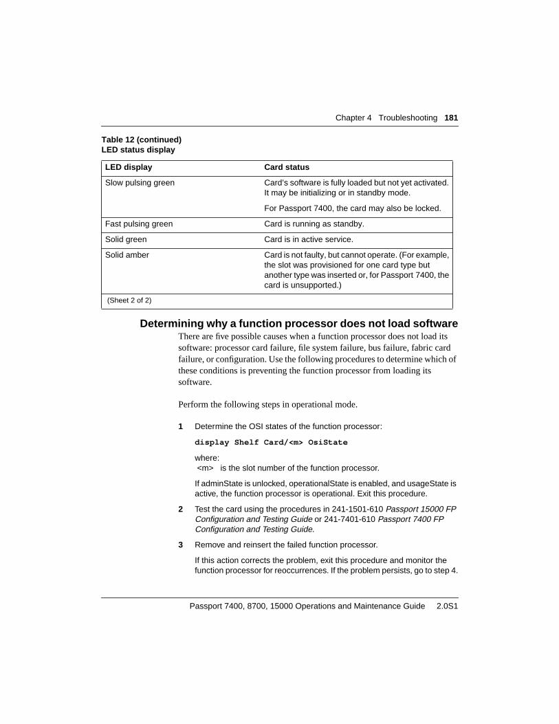
Chapter 4 Troubleshooting 181
Passport 7400, 8700, 15000 Operations and Maintenance Guide 2.0S1
Determining why a function processor does not load softwareThere are five possible causes when a function processor does not load itssoftware: processor card failure, file system failure, bus failure, fabric cardfailure, or configuration. Use the following procedures to determine which ofthese conditions is preventing the function processor from loading itssoftware.
Perform the following steps in operational mode.
1 Determine the OSI states of the function processor:
display Shelf Card/<m> OsiState
where: <m> is the slot number of the function processor.
If adminState is unlocked, operationalState is enabled, and usageState isactive, the function processor is operational. Exit this procedure.
2 Test the card using the procedures in 241-1501-610 Passport 15000 FPConfiguration and Testing Guide or 241-7401-610 Passport 7400 FPConfiguration and Testing Guide.
3 Remove and reinsert the failed function processor.
If this action corrects the problem, exit this procedure and monitor thefunction processor for reoccurrences. If the problem persists, go to step 4.
Slow pulsing green Card’s software is fully loaded but not yet activated.It may be initializing or in standby mode.
For Passport 7400, the card may also be locked.
Fast pulsing green Card is running as standby.
Solid green Card is in active service.
Solid amber Card is not faulty, but cannot operate. (For example,the slot was provisioned for one card type butanother type was inserted or, for Passport 7400, thecard is unsupported.)
Table 12 (continued)LED status display
LED display Card status
(Sheet 2 of 2)

182 Chapter 4 Troubleshooting
241-5701-605 2.0S1
4 Replace the failed function processor.
If this action corrects the problem, exit this procedure and return the failedfunction processor for repair.
5 Determine the OSI states for the file system:
display Fs OsiState
If adminState is unlocked, operationalState is enabled, and usageState isactive, the file system is functioning.
If any of the OSI state attributes for the file system have values other thanthose shown above, the file system is not available. Go to“Troubleshooting the file system” (page 194) to continue thetroubleshooting analysis.
6 If you are working with a Passport 15000, determine the cardPortStatusof the fabric card ports:
display Shelf FabricCard/<n> CardPort/<m>cardPortStatus
If cardPortStatus is OK for the function processor slot, you have verifiedthat the fabric card is functioning.
If cardPortStatus is none or is failed, replace the function processor.
Try using a different slot to provide service until you can replace the shelf.
If the fabric card still does not function, contact Nortel Networks.
7 If you are working with a Passport 7400 series switch, determine thebusTapStatus of the bus taps:
display Shelf Bus/* busTapStatus
If busTapStatus is OK for the function processor slot, you have verifiedthat the bus is functioning.
If busTapStatus is none or busTapStatus is failed, replace the functionprocessor.
Try using a different slot to provide service until you can replace the shelf.
If the bus tap still does not function, contact Nortel Networks.
Determining the cause of a function processor crashWhen a function processor crashes, use the following procedure to determinethe cause.

Chapter 4 Troubleshooting 183
Passport 7400, 8700, 15000 Operations and Maintenance Guide 2.0S1
Perform the following commands in operational mode.
1 Collect diagnostic information about the function processor crash. See“Collecting diagnostic information” (page 183).
2 Replace the failed function processor.
If this action corrects the problem, exit this procedure and return the failedfunction processor for repair.
3 Determine the memory utilization for the processor card:
display Shelf Card/<m> Utilization, Capacity
where: <m> is the slot number of the function processor
Compare the memory and message block usage against the capacity forthe card. If the memory is near or at exhaustion, exit this procedure andreduce the number of features running on the function processor. See“Configuring the software features of an LPT” (page 114).
4 Open a customer service request for Nortel Networks if the previous stepsfail to resolve the problem. See 241-1501-030 Passport 15000 Overviewor 241-7401-030 Passport 7400 Overview.
Include the diagnostic information collected in step 1 for analysis.
Collecting diagnostic informationWhen a processor card detects a critical fault or a recoverable error, it storesdiagnostic information about the error, even if the processor reloads. NortelNetworks support personnel can analyze this diagnostic information and useit for troubleshooting.
You can collect diagnostic information about the last critical fault and the lastrecoverable error on a processor card by displaying operationalsubcomponents of theCard component. These components contain line-by-line detail of the last critical fault (trap data) and last recoverable error. Onceyou have displayed the diagnostic information and stored it for analysis, youcan clear the information from the processor.
You can also collect diagnostic information for analysis by turning on thespooling of debug data to a file and then recreating the error. After you haverecreated the error, the diagnostic information is contained in the debug datafile.

184 Chapter 4 Troubleshooting
241-5701-605 2.0S1
If a function processor that does not load has been in storage, see the table“Troubleshooting function processor problems” (page 175) before collectingdiagnostic information.
Perform the following commands in operational mode.
1 Start a telnet session to the Passport node that is set to log screen outputto a file.
2 Display the diagnostic information about the last critical fault on theprocessor:
display Shelf Card/<m> Diag TrapData Line/*
where:<m> is the slot number of the processor.
3 Display the diagnostic information about the last recoverable error on theprocessor:
display Shelf Card/<m> Diag RecoverableError Line/*
where:<m> is the slot number of the processor.
4 When you are certain the diagnostic information has successfully beenlogged to a file, clear it from memory:
clear Shelf Card/<m> Diag TrapData
clear Shelf Card/<m> Diag RecoverableError
where:<m> is the slot number of the processor.
Troubleshooting control processorsThe most common problems with a control processor are software loadfailures and crashes. These problems can affect both the active and thestandby control processor.
The table “Troubleshooting control processor problems” (page 185) providesdetailed troubleshooting information for control processors.
See the following sections for more information on troubleshooting controlprocessors:
• “Determining why a control processor does not load” (page 189)

Chapter 4 Troubleshooting 185
Passport 7400, 8700, 15000 Operations and Maintenance Guide 2.0S1
• “Determining why the standby control processor does not load”(page 189)
• “Determining the cause of a control processor crash” (page 190)
Table 13Troubleshooting control processor problems
Symptom Probable causes Corrective measures
Control processor does notload.
Processor failure Replace the control processor.See “Replacing a controlprocessor in a single-CP node”(page 99) or “Replacing acontrol processor in a two-CPnode” (page 105).
Fabric card failure
Note: This cause applies onlyto the Passport 15000.
Contact Nortel Networks (see241-1501-030 Passport 15000Overview).
Unsupported PEC
Note: This cause applies onlyto the Passport 7400 seriesswitch.
Replace with a card supportedby Passport 7400. See241-7401-200 Passport 7400Hardware Description for a listof cards supported byPassport 7400.
(Sheet 1 of 4)

186 Chapter 4 Troubleshooting
241-5701-605 2.0S1
Control processor does notload and the Passportcontinually attempts to reboot.
Note: This symptom applies tothe Passport 7400 seriesswitch only.
Incompatibility of the controlprocessor’s firmware with thePassport’s newer shelf (ACshelf NTBP05BA or higher, orDC shelf NTBP64BA orhigher). This problem canhappen when you use an oldercontrol processor card that hasbeen held in storage.
Check if the control processorhas been in storage.
If an older Passport shelf (ACshelf NTBP05AA or DC shelfNTBP64AA) is available, usethat shelf to load the controlprocessor with R1.2.3 or highersoftware. You can then installthe control processor in thenewer shelf.
If an older Passport shelf is notavailable, contact NortelNetworks technical support forfurther instructions (see241-7401-030 Passport 7400Overview). Do not return thecontrol processor to NortelNetworks.
Control processor crashes. Hardware failure Replace the control processor.See “Replacing a controlprocessor in a single-CP node”(page 99) or “Replacing acontrol processor in a two-CPnode” (page 105).
Software problem Collect diagnostic informationfor the control processor andcontact Nortel Networkstechnical support. See241-1501-030 Passport 15000Overview or 241-7401-030Passport 7400 Overview.
Memory exhaustion Reduce the number ofapplications running on thePassport node.
Table 13 (continued)Troubleshooting control processor problems
Symptom Probable causes Corrective measures
(Sheet 2 of 4)

Chapter 4 Troubleshooting 187
Passport 7400, 8700, 15000 Operations and Maintenance Guide 2.0S1
Control processor switchover. OAM Ethernet port failure Troubleshoot the OAMEthernet port. See“Troubleshooting the OAMEthernet port” (page 191).
Table 13 (continued)Troubleshooting control processor problems
Symptom Probable causes Corrective measures
(Sheet 3 of 4)

188 Chapter 4 Troubleshooting
241-5701-605 2.0S1
Standby control processordoes not load.
Processor failure Replace the control processor.See “Replacing a controlprocessor in a single-CP node”(page 99) or “Replacing acontrol processor in a two-CPnode” (page 105).
File system failure See “Troubleshooting the filesystem” (page 194).
Fabric card failure
Note: This cause applies to thePassport 15000 only.
Contact Nortel Networks. See241-1501-030 Passport 15000Overview
Bus failure
Note: This cause applies to thePassport 7400 series switchonly.
Contact Nortel Networks. See241-7401-030 Passport 7400Overview
Standby control processordoes not load and the Passportcontinually attempts to reboot.
Note: This symptom applies tothe Passport 7400 seriesswitch only.
Incompatibility of the controlprocessor’s firmware with thePassport’s newer shelf (ACshelf NTBP05BA or higher, orDC shelf NTBP64BA orhigher). This problem canhappen when you use an oldercontrol processor card that hasbeen held in storage.
Check if the control processorhas been in storage.
If an older Passport shelf (ACshelf NTBP05AA or DC shelfNTBP64AA) is available, usethat shelf to load the controlprocessor with R1.2.3 or highersoftware. You can then installthe control processor in thenewer shelf.
If an older Passport shelf is notavailable, contact NortelNetworks technical support forfurther instructions (see241-7401-030 Passport 7400Overview). Do not return thecontrol processor to NortelNetworks.
Table 13 (continued)Troubleshooting control processor problems
Symptom Probable causes Corrective measures
(Sheet 4 of 4)

Chapter 4 Troubleshooting 189
Passport 7400, 8700, 15000 Operations and Maintenance Guide 2.0S1
Determining why a control processor does not loadThere are a number of reasons why a control processor does not load. Performthe following steps.
1 Verify that one of the control processors is attempting to load.
The control processor’s LED flashes red whenever the control processoris loading. If the control processor is loading, wait a few minutes todetermine if the attempt to load is likely to succeed. If the load attempt issuccessful, exit this procedure. If the load attempt fails, go to step 2.
2 Remove and reinsert the control processor.
If this action corrects the problem, exit this procedure and monitor thecontrol processor for reoccurrences. If the problem persists, go to step 3.
3 Monitor the information output of the control processor on the localterminal as the control processor attempts to load.
If the information output indicates that a specific file cannot be loadedfrom the disk, then the disk is corrupt.
Replace the control processor and restore the disk from a backup copyusing the procedure in 241-6001-023 NMS Architect for Passport UserGuide.
Note: If you are using redundant control processors and the standbycontrol processor now crossloads, reformat the standby controlprocessor’s disk. See “Formatting a disk” (page 129).
If the loading information indicates that bus errors are occurring, contactNortel Networks (see 241-1501-030 Passport 15000 Overview or241-7401-030 Passport 7400 Overview).
Determining why the standby control processor does not loadThere are a number of reasons why a standby control processor does not load.
Perform the following steps in operational mode.
1 Test the control processor using the procedures from 241-1501-610Passport 15000 FP Configuration and Testing Guide or 241-7401-610Passport 7400 FP Configuration and Testing Guide.
2 Replace the standby control processor.
See “Replacing a control processor in a single-CP node” (page 99) or“Replacing a control processor in a two-CP node” (page 105). If this

190 Chapter 4 Troubleshooting
241-5701-605 2.0S1
action corrects the problem, exit this procedure and return the failedcontrol processor for repair.
3 Determine the OSI states for the file system:
display Fs OsiState
If adminState is unlocked, operationalState is enabled, and usageState isactive, the file system is functioning.
If any of the OSI state attributes for the file system have values other thanthose shown above, the file system is not available. Go to“Troubleshooting the file system” (page 194) to continue thetroubleshooting analysis.
4 If you are using a Passport 15000, determine the cardPortStatus of thefabric card ports:
display Shelf FabricCard/<n> CardPort/*
If CardPortStatus is OK for the standby control processor slot, you haveverified that the fabric is functioning.
If CardPortStatus is none or is failed, replace the standby controlprocessor. See “Replacing a control processor in a single-CP node”(page 99) or “Replacing a control processor in a two-CP node”(page 105).
If the fabric card port still does not function, contact Nortel Networks.
5 If you are using a Passport 7400 series switch, determine thebusTapStatus of the bus taps:
display Shelf Bus/* busTapStatus
If busTapStatus is OK for the standby control processor slot, you haveverified that the bus is functioning.
If busTapStatus is none or busTapStatus is failed, replace the standbycontrol processor. See “Replacing a control processor in a single-CPnode” (page 99) or “Replacing a control processor in a two-CP node”(page 105).
If the bus tap still does not function, contact Nortel Networks.
Determining the cause of a control processor crashPerform the following steps in operational mode.
1 Collect diagnostic information about the control processor crash. See“Collecting diagnostic information” (page 183).

Chapter 4 Troubleshooting 191
Passport 7400, 8700, 15000 Operations and Maintenance Guide 2.0S1
2 Replace the failed control processor.
See “Replacing a control processor in a single-CP node” (page 99) or“Replacing a control processor in a two-CP node” (page 105). If thiscorrects the problem, exit this procedure and return the failed controlprocessor for repair.
3 Determine the memory utilization for the control processor:
display Shelf Card/<m> Utilization, Capacity
where: <m> is the slot number of the control processor.
Compare the memory and message block usage against the capacity forthe control processor. If the memory is near or at exhaustion, exit thisprocedure and reduce the number of features running on the Passportnode. See “Configuring the software features of an LPT” (page 114).
4 Open a customer service request for Nortel Networks if the previous stepsfail to resolve the problem. See 241-1501-030 Passport 15000 Overviewor 241-7401-030 Passport 7400 Overview.
Include the diagnostic information collected in step 1 for analysis.
Troubleshooting the OAM Ethernet portThere are two conditions related to the OAM Ethernet port component thatcan cause a CP switchover.
• Failure of the initial port test: If theswitchoverOnFailureattribute is setto enabled, the operational attributestandbyStatus has the valueavailable. Any failure of the initial port tests on the Ethernet port initiatesa CP switchover.
• Failure of the steady state link: If there is an absence of traffic on the linkfor a period of more than 25 seconds, a time domain reflectometry (TDR)test is performed on the link. If the TDR test fails and theswitchoverOnFailureandstandbyStatusattributes are set to enabled andavailable respectively, a CP switchover occurs.
Note: If either of these two error conditions occur, only one CPswitchover happens. The operational attributes activeStatus andstandbyStatus allow the port to keep track of the states of both OAMEthernet ports so that the CP can correctly determine when a switchoveris appropriate.

192 Chapter 4 Troubleshooting
241-5701-605 2.0S1
Note: If switchoverfailure is enabled and lp/0 oamenet standbystatus isset to available, an approximate two minute loss of Ethernet connectivityon both standby and active CP OAM Ethernet ports will trigger a CPswitchover and an OAM Ethernet port initialization failure on the newactive CP. The OAM Ethernet port will be locked and no other telnetconnections can be established until you lock or unlock the active CPOAM Ethernet port.
Note: If the OAM Ethernet port test fails during the initialization of anactive CP, the CP Ethernet port will remain locked in the not availablestate even if the cause of the failure disappears. For example, if theEthernet cable is disconnected and then reconnected, the CP Ethernetport will remain locked in the not available state.
See the following sections for information on testing the OAM Ethernet port:
• “Types of OAM Ethernet port tests” (page 192)
• “Testing the OAM Ethernet port” (page 192)
Types of OAM Ethernet port testsThere are four tests that you can execute on the Ethernet port. The first threeverify the port device; the fourth one verifies the link.
• The hardware test verifies the Ethernet controller hardware logic.
• The configuration test verifies the configuration of the device driver.
• The memory map test verifies the memory map for receive and transmitbuffers lists.
• The TDR test detects open or short circuits and their distance from theport.
Testing the OAM Ethernet portPerform the following steps in operational mode.

Chapter 4 Troubleshooting 193
Passport 7400, 8700, 15000 Operations and Maintenance Guide 2.0S1
1 Lock the OAM Ethernet port:
lock -force -forever Lp/0 oamEnet/0
Note 1: Use the -force option to place the port in an immediate lockedstate, without going through the shutting down state.
Note 2: Use the -forever option to lock the port permanently until youissue an unlock command. Without this option, the port locks for amaximum of 5 minutes before being unlocked automatically.
2 Assign the type of test to be conducted:
set Lp/0 oamEnet/0 Test type <type>
where:<type> is one of hardwareLogic, configuration, memoryMap, or tdr.
Note: These four tests are mutually exclusive. They cannot executeconcurrently.
3 Initiate the test:
start Lp/0 oamEnet/0 Test
Note: It is not necessary to use the stop command as the test takes avery small amount of time to execute. If an error occurs and the test doesnot terminate properly, the hardware detects this and terminates the test.
4 Review the results of the test:
display Lp/0 oamEnet/0 Test
The tests return pass/fail information. If an Ethernet port fails any test,switch to the standby CP and contact your Nortel Networksrepresentative.
5 If the Ethernet port passes all tests, unlock the port:
unlock Lp/0 oamEnet/0
CAUTIONPotential loss of NMS connectivityLocking the OAM Ethernet port disconnects allconnections to the Passport that use this port. Ensurethat the connection through which you are issuing thelock command does not use the OAM Ethernet port.

194 Chapter 4 Troubleshooting
241-5701-605 2.0S1
Troubleshooting the file systemFile system problems relate to either the file system software or to the disksubsystem on the control processor. The table “Troubleshooting file systemproblems” (page 194) details how to troubleshoot the file system.
See the following sections for more information on troubleshooting the filesystem:
• “Determining why a file cannot be saved” (page 195)
• “Determining why the file system is not operational” (page 196)
• “Testing a disk” (page 197)
• “Interpreting disk test results” (page 200)
Table 14Troubleshooting file system problems
Symptom Probable causes Corrective measures
File system not operational File system locked Issue unlock Fs command.
All disks failed Replace the controlprocessors. See “Replacing acontrol processor in a single-CP node” (page 99) or“Replacing a control processorin a two-CP node” (page 105).
(Sheet 1 of 2)

Chapter 4 Troubleshooting 195
Passport 7400, 8700, 15000 Operations and Maintenance Guide 2.0S1
Determining why a file cannot be savedIf you cannot save a file, there are two possible causes: the file system is notfunctioning or it is full. The following procedure helps you determine whyyou cannot save a file.
Perform the following steps in operational mode.
1 Determine the OSI states for the file system:
display Fs OsiState
If adminState is unlocked, operationalState is enabled, and usageState isactive, the file system is functioning. Exit this procedure.
If any of the OSI state attributes for the file system have values other thanthose shown above, the file system is not available. See the procedure“Determining why the file system is not operational” (page 196) tocontinue through troubleshooting analysis.
2 Determine the available free space on the file system:
display Fs freeSpace
Cannot save to disk File system locked Issue the unlock Fs command.
Disks are full Remove unnecessary filesfrom the disk. To removeunnecessary provisioning files,issue the tidy Prov command.To remove unnecessaryspooling files use theManagement Data Provider, orissue the remove Fs command.To remove unnecessarysoftware files, see241-5701-270 Passport 7400,8700, 15000 SoftwareInstallation Guide.
Table 14 (continued)Troubleshooting file system problems
Symptom Probable causes Corrective measures
(Sheet 2 of 2)

196 Chapter 4 Troubleshooting
241-5701-605 2.0S1
If the available free space is less than the size of the file to be saved,remove any unnecessary files from the disk. To remove unnecessaryprovisioning files, issue the tidy Prov command. To remove unnecessaryspooling files use the Management Data Provider, or issue the remove Fscommand. To remove unnecessary software files, see 241-5701-270Passport 7400, 8700, 15000 Software Installation Guide.
Determining why the file system is not operationalPerform the following steps in operational mode.
1 Determine the OSI states for the file system:
display Fs OsiState
If adminState is unlocked, operationalState is enabled, and usageState isactive, the file system is functioning. Exit this procedure.
If adminState is locked, consult with the operator who took the file systemout of service to verify that the file system can now be unlocked and thenissue the unlock Fs command. Exit this procedure.
If operationalState is disabled, it is likely that all disks have failed. Go tostep 2.
2 Lock and unlock the failed file system:
lock Fs
unlock Fs
By locking and then immediately unlocking the failed file system, you cansometimes clear a software related problem.
3 Determine the OSI states for the disks:
display Fs Disk/* OsiState
If operationalState is disabled for a given disk, that disk has failed.
4 Lock and unlock the failed disk:
lock Fs Disk/<n>
unlock Fs Disk/<n>
where:<n> is the number of the failed disk. The disk number corresponds to theslot number of the control processor holding the disk.

Chapter 4 Troubleshooting 197
Passport 7400, 8700, 15000 Operations and Maintenance Guide 2.0S1
By locking and then immediately unlocking the failed disk, you cansometimes clear a software related problem. If the disk still fails, go tostep 5.
5 Perform a disk test.
See “Testing a disk” (page 197).
6 If the previous steps have failed to restore the disk, replace the controlprocessor that holds the failed disk. See “Replacing a control processorin a single-CP node” (page 99) or “Replacing a control processor in a two-CP node” (page 105).
Testing a diskTest a disk only when you suspect a fault in the disk hardware. Note that youcannot test the disk on the active control processor. The procedure “Testing adisk” (page 198) details how to test a disk.
The disk tests cannot tolerate any interruptions from normal disk operations,so you must lock the disk before testing it. A locked disk cannot performnormal disk operations.
There are four types of tests for disks:
• Disk read test—reads every sector on the disk once, marking bad sectors.If the test detects an error, proceed with the file system check test. Thistest takes about four minutes.
• Flaky bit detection test—reads every sector on the disk twice andcompares the two read results. If the test reveals an error, proceed withthe file system check test. This test takes about eight minutes.
• File system check test—performs a file system sanity check, frees lostclusters, and attempts to correct bad sectors. This test takes a fewseconds.
You must run the file system check test if either the disk read test or flakybit detection test indicate errors.
• Surface analysis test—writes a pattern to the disk and reads back thepattern to determine the condition of the magnetic surface of the disk.This test destroys the contents of the disk. Only use this test if all otherdisk tests have failed to reveal the error. This test takes about 16 minutes.
198 Chapter 4 Troubleshooting
241-5701-605 2.0S1
Only test the standby disk on a dual-disk node. If the disk you want to test iscurrently active, switch control between the active and standby controlprocessors. See “Switching between active and standby processor cards”(page 124).
Testing a diskPerform the following steps in operational mode.
1 Set the test type:
set Fs Disk/<n> Test type <type>
where:<n> is the number of the disk to be tested. The disk number correspondsto the slot number of the control processor that holds the disk.<type> is one of diskRead, flakyBitDetection, filesystemCheck, orsurfaceAnalysis.
2 If you are working on a single-disk node, lock the file system:
lock Fs
3 Lock the disk:
lock Fs Disk/<n>
where:<n> is the number of the disk to be tested.
4 Start the test:
CAUTIONRisk of operational data records lossPerforming a disk test can cause a loss of operationaldata. When you lock a disk on a single-CP node,Passport cannot spool operational data records to thedisk.
CAUTIONRisk of data lossNever initiate a surface analysis test on a single-disksystem. The test erases all data on the disk andreformats the disk.

Chapter 4 Troubleshooting 199
Passport 7400, 8700, 15000 Operations and Maintenance Guide 2.0S1
start Fs Disk/<n> Test
where:<n> is the number of the disk to be tested.
5 If you want to stop the test before it is complete, enter
stop Fs Disk/<n> Test
where:<n> is the number of the disk being tested.
Note: The test does not always stop immediately. The test completes itscurrent cycle before ending.
6 Unlock the disk:
unlock Fs Disk/<n>
where:<n> is the number of the disk that was tested.
7 If you previously locked the file system, unlock it:
unlock Fs
If you performed a surface analysis test, proceed with step 8. If you aredoing any other disk tests, proceed to step 10.
8 If you performed a surface analysis test, reset the control processor:
reset Shelf Card/<m>
where:<m> is the number of the control processor containing the disk youtested.
The standby control processor (CP) attempts to load from its disk fourtimes before it initiates a crossload from the active CP.
9 When the standby CP comes up, use the sync command to restore filesystem synchronization:
sync Fs
10 Display the disk test results:
display Fs Disk/<n> Test Results
where:<n> is the number of the disk that you tested.
See “Interpreting disk test results” (page 200) for information on thevalues of the result attributes.

200 Chapter 4 Troubleshooting
241-5701-605 2.0S1
Interpreting disk test resultsThe table “Disk test results” (page 200) describes the possible results of thedisk tests.
Table 15Disk test results
Attribute Use
causeOfTermination Displays the reason the disk test ended. The reason can be one of thefollowing:
• testCountReached: The test ran the specified number of times in theattribute testCount and ended normally.
• error: An error terminated the test. The error is described in thenatureOfError attribute.
• neverStarted: The disk test has not started.
• stoppedByOperator: An operator issued a Stop Shelf Disk Testcommand.
• testTimeExpired: The duration of the test expired.
• testRunning: The test is still running.
• unknown: The test terminated for unknown reasons.
• internalError: An internal error terminated the test.
elapsedTime Displays the elapsed time (in minutes) since the test started.
natureOfError Describes the type of the error found by a test. The type of error can be oneof the following:
• logical: A filesystem check test followed by a synchronization can fix theerror.
• media: There is a suspected fault in the disk hardware.
• failedToComplete: The test terminated.
results Displays all results associated with the attributes in this table.
(Sheet 1 of 2)

Chapter 4 Troubleshooting 201
Passport 7400, 8700, 15000 Operations and Maintenance Guide 2.0S1
Troubleshooting the data collection systemProblems with the data collection system are usually related to devicecapacity.
The table “Troubleshooting problems with the data collection system”(page 201) details how to troubleshoot the data collection system.
severity Displays the severity of the error found by the test. The severity can be oneof the following:
• no lost data
• lost data
• hardware problem
testExecutionCount Displays the number of times the test ran.
Table 16Troubleshooting problems with the data collection system
Symptom Probable causes Corrective measures
A network managementinterface or the spooler is notreceiving the data collectioninformation (alarm, SCN, log,and debug data) it requested.
The control processor’smessage block usage is closeto capacity, probably due torouting table updates.
At least one networkmanagement interface or thespooler will be receiving all ofthe data collection information.Check all of the networkmanagement interfaces in thenetwork, or the spooling files onthe disk, to locate theinformation.
Table 15 (continued)Disk test results
Attribute Use
(Sheet 2 of 2)

202 Chapter 4 Troubleshooting
241-5701-605 2.0S1

203
Passport 7400, 8700, 15000 Operations and Maintenance Guide 2.0S1
Chapter 5Statistics
The data collection system collects Passport statistics. When enabled, the datacollection collects the values of particular attributes and spools them to disk.Once on disk, you can remove statistics files using the Management DataProvider. See 241-6001-309NMS Management Data Provider User Guidefor details.
For more information on the data collection system, see “Working with thedata collection system” (page 130). For more information on Passportstatistics, see 241-5701-600Passport 7400, 8700, 15000 Operations andMaintenance Fundamentals. For complete information on statistics attributescollected for each component, see 241-5701-060Passport 7400, 8700, 15000Components.
See the following sections for more information on statistics:
• “Enabling statistics collection” (page 203)
• “Displaying statistics collection information” (page 205)
Enabling statistics collectionBy default, the data collection system does not collect statistics data. Theagent queue size for statistics data is set to 0 (zero), which causes the agent todiscard all statistics data.

204 Chapter 5 Statistics
241-5701-605 2.0S1
To turn on statistics collection for a logical processor, you can use thefollowing typical settings:
• maximum agent queue size: 100
• spooling option: on
• maximum files in closed directory: 200
For additional guidelines on setting these parameters, see thePassportEngineering Notes and Guidelines
Use the following procedure to configure the data collection system to collectPassport statistics for a logical processor and spool them to disk. To performthis procedure, your userid must have a minimum scope of device and aminimum impact of service.
Perform the following steps in provisioning mode. For information onworking in provisioning mode, see “Changing the configuration using theprovisioning system” (page 33).
1 If you want to reset the statistics agent queue size on an LP, add anOverride component:
add Lp/<n> Eng DataStream/stats Override
where:<n> is the number of the logical processor.
2 Set the maximum agent queue size for the LP:
set Lp/<n> Eng Ds/stats Ov agentQueueSize <size>
where:<n> is the number of the logical processor.<size> is the maximum number of records in the queue. Use a valuebetween 20 and 200, depending on the number of applications configuredon that LP to generate records.
3 Turn the spooling option on:
set Col/stats Sp spool on
The value must be set to on to permit spooling of Passport statistics. If setto off, statistics do not spool to the disk.

Chapter 5 Statistics 205
Passport 7400, 8700, 15000 Operations and Maintenance Guide 2.0S1
4 Set the maximum number of files that can exist in a closed directory:
set Col/stats Sp maxFile <number>
where:<number> specifies the number of files to be kept on disk (any integerbetween 1 and 200). If you do not want the spooler to limit the number ofstatistics files kept on disk, enter 0 (zero). If you set this attribute to 0(zero), you can fill the disk with statistics data files. Carefully monitor diskusage.
Displaying statistics collection informationUse this procedure to display information about the number of statisticsrecords processed by the data collection system since the last processorrestart.
The following information is available for statistics collectors, agents, andspoolers:
• records currently in the queue (currentQueueSize attribute)
• received records (recordsRx attribute)
• discarded records (recordsDiscarded attribute)
Statistics agents also provide information on the number of records thatapplications were unable to generate due to some limitation(recordsNotGenerated attribute).
Perform the following commands in operational mode.
1 Display the queue information for the statistics collector:
display Col/stats Statistics
2 Display the queue information for the statistics agents:
display Col/stats Ag/* Statistics, AgentStatistics
This command displays a table showing queue information for eachlogical processor.
An agent discards records if its queue size is too small. If an agent isdiscarding records, you may want to increase the agent queue size of itsLP. However, you must be careful not to overload system resources withhigh queue size settings. For guidelines on determining appropriate

206 Chapter 5 Statistics
241-5701-605 2.0S1
values for agent queues sizes, see the Passport Engineering Notes andGuidelines.
When records are not generated, it usually indicates that some re-engineering is necessary.
3 Display the queue information for the statistics spooler:
display Col/stats Sp Statistics
A spooler discards records if its spooling option is turned off while thespooler still contains records.

207
Passport 7400, 8700, 15000 Operations and Maintenance Guide 2.0S1
Chapter 6Accounting
The data collection system collects accounting records from the logicalprocessors. It collects accounting records when a call clears and at acollection time in the time-of-day accounting (TODA) schedule.
In most cases, you can use the data collection defaults for accountinginformation collection. See “Working with the data collection system”(page 130) for more information on data collection defaults.
For more information on Passport accounting, see 241-5701-600Passport7400, 8700, 15000 Operations and Maintenance Fundamentals. You can alsofind detailed information about accounting in 241-5701-650Passport 7400,8700, 15000 Accounting Reference.
See the following sections for more information on accounting:
• “Configuring accounting” (page 207)
• “Viewing accounting data” (page 208)
• “Configuring a time-of-day accounting schedule” (page 208)
Configuring accountingUse the following procedure to configure the data collection system to collectPassport accounting information on the node.
Perform the following steps in provisioning mode. For information onworking in provisioning mode, see “Changing the configuration using theprovisioning system” (page 33).

208 Chapter 6 Accounting
241-5701-605 2.0S1
1 If you want to reset the accounting agent queue size on an LP, add anOverride component:
add Lp/<n> Eng DataStream/accounting Override
where:<n> is the number of the logical processor.
Note: When you add a DataStream component, Passport automaticallyadds an Override (Ov) component.
2 Set the maximum queue size for the LP:
set Lp/<n> Eng Ds/acc Ov agentQueueSize <size>
where:<n> is the number of the logical processor.<size> is the maximum number of records. Using a value of 0 will turnaccounting record collection off for the specified LP.
3 Turn the spooling option on:
set Col/acc Sp spool on
The value must be set to on to permit spooling of Passport accountinginformation. If set to off, accounting information does not spool to the disk.
4 Set the maximum number of files that can exist in a closed directory:
set Col/acc Sp maxFile <number>
where:<number> specifies the number of files to be kept on disk (any integerbetween 1 and 200). If you do not want the spooler to limit the number ofaccounting files kept on disk, enter 0 (zero).
Viewing accounting dataYou can use Network Management System (NMS) to view accounting data.Refer to 241-6001-309NMS Management Data Provider User Guide formore information.
Configuring a time-of-day accounting scheduleYou can define when Passport collects accounting records by setting up atime-of-day accounting (TODA) schedule. You use thecollectionTimesattribute to specify the TODA schedule. These scheduled times apply to a

Chapter 6 Accounting 209
Passport 7400, 8700, 15000 Operations and Maintenance Guide 2.0S1
24-hour period. The schedule repeats the following day unless you set up anew schedule. The procedure “Configuring a time-of-day accountingschedule” (page 208) describes how to set thecollectionTimes attribute.
Use the following guidelines to set up a TODA schedule:
• Limit the number of entries to 24.
• Enter collection times in any order. However, accounting data collectionoccurs chronologically.
• Only include entries that are at least one hour apart and at most 12 hoursapart. If you request data collection before one hour has passed since thelast collection, Passport waits for one hour to pass before collecting thedata. This occurs even if you change the time-of-day accounting scheduleor adjust network time.
If you do not provision TODA, the virtual circuit (VC), or ATM, theaccounting system starts its own 12-hour accounting timer. If you provisionany valid collection times, Passport uses the TODA schedule.
ThecollectionTimes attribute exists for allCollector component instances.However, if you set this attribute for anyCollectorcomponent other than theaccounting instance, it has no effect.
Perform the following steps in provisioning mode. For information onworking in provisioning mode, see “Changing the configuration using theprovisioning system” (page 33).
1 Display the current setting for time-of-day accounting:
display Col/accounting collectionTimes
2 Add schedule times for accounting record collection:
set Col/accounting collectionTimes <time>
where:<time> is the time of a scheduled collection (conform to the rules andrestrictions listed previously). Use a 24-hour time in the format HH:MM.You can enter more than one scheduled collection time by separatingthem with a space.

210 Chapter 6 Accounting
241-5701-605 2.0S1
3 Remove a scheduled collection time, as required:
set Col/accounting collectionTimes ~<time>
where:<time> is the time of the scheduled collection you want to remove.

211
Passport 7400, 8700, 15000 Operations and Maintenance Guide 2.0S1
Chapter 7Security
You maintain Passport security by controlling user access and a list of IPaddresses allowed to access your node. See the following sections forinformation on managing Passport security:
• “User administration” (page 211)
• “Controlling user sessions” (page 219)
• “Configuring authorized IP access” (page 223)
For more information on Passport security, see 241-5701-600Passport 7400,8700, 15000 Operations and Maintenance Fundamentals.
User administrationThe following procedures allow you to maintain Passport user information.
• “Adding a new user” (page 212)
• “Copying an existing userID for a new user” (page 214)
• “Changing a password” (page 215)
• “Changing user attributes” (page 218)
• “Deleting a userID” (page 218)

212 Chapter 7 Security
241-5701-605 2.0S1
Adding a new userWhen you first set up a node, you must define at least one userID withsystemAdministration impact. Nortel Networks recommends that at least twouserIDs exist with systemAdministration impact.
Nortel Networks also recommends that you define a userID that allows youto view Passport alarms on the Network Management System (NMS)workstation. This userID must have a scope of network, impact of service,and allowed access of FMIP. For more information, see 241-6001-303NMSAdministrator Guide.
Unless this is a new node, you must have systemAdministration impact to adda new user.
Perform the following steps in provisioning mode. For information onworking in provisioning mode, see “Changing the configuration using theprovisioning system” (page 33).
1 Add a Userid component:
add accessControl Userid/<userID>
where:<userID> is from one to eight characters in length.
2 Set the password:
set Ac Userid/<userID> password <password>
where:<userID> is from one to eight characters in length.<password> is from five to eight characters in length.
Note 1: Passwords are case-sensitive.
Note 2: Only users with an impact level of systemAdministration or highercan set a password.
Note 3: When you set a password, it displays on the user interface. Onceset, the password cannot be displayed.
3 Set the customer identifier (CID):
set Ac Userid/<userID> customerIdentifier <identifier>
where:<userID> is from one to eight characters in length.

Chapter 7 Security 213
Passport 7400, 8700, 15000 Operations and Maintenance Guide 2.0S1
<identifier> is any number between 0 and 8191. The CID constrains theuser to those components that belong to the same CID, except 0 whichcan access any component.
4 Set the command scope for the user:
set Ac Userid/<userID> commandScope <scope>
where:<userID> is from one to eight characters in length.<scope> is one of application (default), device, or network. Thecommand scope is automatically set to the default of application if you donot enter this command.
Note: In the NMS for Architect for Passport tool, <scope> must be set tonetwork.
5 Set the command impact for the user:
set Ac Userid/<userID> commandImpact <impact>
where:<userID> is from one to eight characters in length.<impact> is one of passive (default), service, configuration, orsystemAdministration. The command impact is automatically set to thedefault of passive if you do not enter this command.
6 Set the allowed network management interfaces:
set Ac Userid/<userID> allowedAccess <interface>
where:<userID> is from one to eight characters in length.<interface> is one or more of local (default), FMIP, telnet, or FTP. Thisvalue constrains the user to the specified interface types. The allowedinterface is automatically set to the default of local if you do not enter thiscommand.
The following indicates which interface to use for each tool:
• directly connected VT100 terminal—local
• NMS Integrated Command Console—FMIP
• NMS surveillance—FMIP
• Architect for Passport—FMIP
• standard telnet—telnet
• OMS network management system—telnet
• standard FTP—FTP

214 Chapter 7 Security
241-5701-605 2.0S1
If you want to disallow an interface, you can type the interface namepreceded by a tilde (~) character. For example, to allow access from allinterfaces except FTP, enter the following:
set Ac Userid/<userID> allowedAccess local fmip telnet~ftp
7 Set the allowed out access for the user:
set Ac Userid/<userid> allowedOutAccess <interface>
where:<userid> is from one to eight characters in length.<interface> is either telnet or ~telnet. If you want to allow the user toestablish outgoing telnet connections, use telnet. If you don’t want theuser to establish outgoing telnet connections, use ~telnet. The default is~telnet.
8 Optionally, you can set the user login directory for file system commandsor FTP commands:
set Ac Userid/<userID> loginDirectory <directory>
where:<userID> is from one to eight characters in length.<directory> is the user’s login directory.
Note: The directory is automatically set to the default of “/” if you do notenter this command. “/” is the root directory.
9 Optionally, you can check your new userID:
display Ac Userid/<userID>
where:<userID> is from one to eight characters in length.
Copying an existing userID for a new userYou can copy a userID and all of its attributes, except password attributes, ifyou have a large number of users that will have the same attributes where theonly difference is the userID and the password. This technique reduces theneed to reset attributes every time you add a new user. Once you copy aUserid component, you only need to change the password. If you want tochange other attributes, see “Changing user attributes” (page 218). You musthave systemAdministration impact to copy an existing userID.

Chapter 7 Security 215
Passport 7400, 8700, 15000 Operations and Maintenance Guide 2.0S1
Perform the following steps in provisioning mode. For information onworking in provisioning mode, see “Changing the configuration using theprovisioning system” on page 33.
1 Copy the Userid component:
copy -s(Ac Userid/<olduserID>) -d(Ac Userid/<newuserID>) Prov
where:<olduserID> is the existing userID.<newuserID> is the userID of the new user.
2 Set the password for the new userID:
set Ac Userid/<newuserID> password <password>
where:<newuserID> is the userID of the new user.<password> is from five to eight characters in length.
Note: When you set a password, it displays on the user interface. Onceset, the password cannot be displayed.
3 If you want to change the attributes of the new Userid component, do sowith the set command.
Changing a passwordThe following procedure explains how to change the password on an existinguserID. Individual users cannot change their passwords. Only the systemadministrator (systemAdministration impact) can change a password.
When you change a password, the actual characters of the password appearon the user interface. To keep passwords private, make sure your workstationis in a secure area before changing a password. For more information onpassword security, see “Secure method for setting a password” on page 216.
Perform the following command in provisioning mode. For information onworking in provisioning mode, see “Changing the configuration using theprovisioning system” on page 33.
1 Set the password:
set Ac Userid/<userID> password <password>

216 Chapter 7 Security
241-5701-605 2.0S1
where:<userID> is the name of the userID for which you are changing thepassword.<password> is the new password. The password must be from five toeight characters long.
Secure method for setting a passwordWhen setting an initial password for a user or changing an existing password,there are the following security risks:
• The actual characters of the password appear on the user interface.
• When you are not using a local session, the password travels over thenetwork in easy-to-read ASCII format.
• Local and telnet sessions have a command recall queue, which stores thelast 10 commands. The command in which you set the password can berecalled from the queue using the Up-Arrow and Down-Arrow keys.
The following procedure describes a method for minimizing the security riskwhen setting a password. It assumes that you have a physically securePassport where you can make password changes and that you need to changea password on another, insecure Passport. It also assumes that the user ID thatneeds the changed password exists on both the secure and the insecure node.
Only the system administrator (systemAdministration impact) can change apassword.
1 Log into a secure Passport node. You should access this node from aworkstation in a physically secure area using a local VT100 session. Youcan also use a telnet session as long as you use a secure connection. Donot establish a telnet session across a public network.
2 Start provisioning mode.
start Prov
3 Set the password.
set Ac Userid/<userID> password <password>
where:<userID> is name of the user ID for which you are setting the password<password> is the password. The password must be from five to eightcharacters long.

Chapter 7 Security 217
Passport 7400, 8700, 15000 Operations and Maintenance Guide 2.0S1
4 Save the Userid component with the changed password.
save -component(Ac Userid/<userID>) -file(<name>) Prov
where:<userID> is name of the user ID with the changed password<name> is a descriptive name for the partial saved view.
Note: When you save a partial saved view i to the file system, uses itscomplete name in the form <name>.part.<num>, where <num> is anautomatically generated sequence number. The save Prov commandresponds with the complete name of the view, for example,UserRoot.part.001.
5 End provisioning mode.
end Prov
6 Log out of the secure node to clear the command recall queue.
logout
7 Transfer the partial saved view containing the Userid component from thesecure node to an insecure node using FTP. You must use the completename of the view, which is in the form <name>.part.<num>.
Note: Since FTP does not have a secure login mechanism, do not usethe same user ID for FTP access as you have stored in the partial savedview.
a. Transfer the partial saved view from the secure node to a workstationusing FTP. You can find the partial saved view you created in the/provisioning directory of the Passport node.
b. Transfer the partial saved view from the workstation to the insecurenode using FTP. Put it in the /provisioning directory.
8 Log into the insecure node.
9 Start provisioning mode.
start Prov
10 Load the partial saved view.
load -file(<viewname>) Prov
where:<viewname> is the complete name of the partial saved view, which is inthe form <name>.part.<num>.
11 Verify that the provisioning changes you have made are acceptable.

218 Chapter 7 Security
241-5701-605 2.0S1
check Prov
Correct any errors, and then verify the provisioning changes again.
12 If you want these changes as well as other changes made in the edit viewto take effect immediately, activate and commit the provisioning changes.
activate Provconfirm Provcommit Prov
For more information on this step, see “Activating and committingprovisioning changes” on page 35.
13 End provisioning mode.
end Prov
Changing user attributesThis section explains how to change the user attributes of an existingUseridcomponent. For a description of all user attributes, see “Adding a new user”(page 212). You can also find descriptions of the attributes in 241-5701-600Passport 7400, 8700, 15000 Operations and Maintenance Fundamentals.You must have systemAdministration impact to change user attributes.
Perform the following command in provisioning mode. For information onworking in provisioning mode, see “Changing the configuration using theprovisioning system” on page 33.
1 Change the attributes of the Userid component:
set Ac Userid/<userID> <attribute> <value>
where:<attribute> is any attribute that corresponds to userid.<value> is any value that corresponds to the chosen attribute.
Deleting a userIDThis section explains how to delete an existing userID. You must havesystemAdministration impact to delete a user.
Perform the following command in provisioning mode. For information onworking in provisioning mode, see “Changing the configuration using theprovisioning system” on page 33.

Chapter 7 Security 219
Passport 7400, 8700, 15000 Operations and Maintenance Guide 2.0S1
1 Remove the Userid component:
delete accessControl Userid/<userID>
where:<userID> is from one to eight characters in length.
Controlling user sessionsThe following procedures allow you to control the user connections (sessions)to your Passport node:
• “Displaying the number of user sessions” (page 219)
• “Displaying users” (page 220)
• “Restricting access through a specific interface” (page 220)
• “Terminating a user session” (page 220)
• “Immediately terminating multiple user sessions” (page 221)
• “Releasing a locked interface” (page 222)
• “Enabling and disabling password encryption for telnet sessions”(page 222)
Displaying the number of user sessionsThe following procedure lets you determine how many users are logged intothe node and which network management interfaces they are using.
Perform the following steps in operational mode.
1 Display the number of current sessions of a particular networkmanagement interface:
display Nmis <interface> activeSessions
where:<interface> is one of telnet, local, fmip, or ftp.
2 Display the sessions logged on to a particular network managementinterface:
list Nmis <interface> *
where:<interface> is one of telnet, local, fmip, or ftp.

220 Chapter 7 Security
241-5701-605 2.0S1
Displaying usersUse the following procedure to display the users logged into each networkmanagement interface.
Perform the following command in operational mode.
1 Display all the users logged on to a network management interface:
display Nmis <interface> Session/* userid
where:<interface> is one of telnet, local, fmip, or ftp.
Restricting access through a specific interfaceThe following procedure explains how to terminate access through a specifiedinterface by placing the interface out of service. To place an interface out ofservice, you lock the appropriate interface component. All current sessionscontinue until they are complete and no further sessions start until you issuethe unlock command.
You must have systemAdministration impact to perform this procedure. Youcannot restrict access through the local interface.
Perform the following command in operational mode.
1 Lock the interface component:
lock Nmis <interface>
where:<interface> is one of ftp, fmip, or telnet. You can lock any interfacecomponent except the interface you are currently using to access thenode. The interface moves to a shutting-down state and does not allowset up of further sessions. All current sessions continue until they arecomplete.
If you lock the telnet interface while you have a current telnet session, youcan still set up outgoing telnet client connections (using the telnet Vrcommand), but you cannot set up new incoming telnet sessions.
Terminating a user sessionYou can terminate individual user sessions using the clear Nmis <interface>Session command against that session.

Chapter 7 Security 221
Passport 7400, 8700, 15000 Operations and Maintenance Guide 2.0S1
You must have systemAdministration impact to terminate a user session. Youcannot terminate a user session on the local interface.
Perform the following steps in operational mode.
1 Display all current sessions:
list Nmis <interface> *
where: <interface> is one of telnet, fmip, or ftp.
This command lists all sessions on the interface. Each session has aunique instance number.
2 Clear the Session component:
clear Nmis <interface> Session/<n>
where:<interface> is one of telnet, fmip, or ftp.<n> is the session number you want to terminate.
The user session terminates. If a telnet session has a client connection(as represented by the Client subcomponent), the command alsoterminates the client connection.
Immediately terminating multiple user sessionsYou can immediately terminate multiple user sessions by immediatelyshutting down an interface using the lock command with the force option. Allsessions on the interface terminate and new sessions cannot be set up.
You must have systemAdministration impact to terminate multiple usersessions. You cannot terminate user sessions on the local interface.
To terminate an individual user session, see “Terminating a user session”(page 220).
Perform the following command in operational mode.
1 Force the lock on the interface component:
lock -force Nmis <interface>
222 Chapter 7 Security
241-5701-605 2.0S1
where:<interface> is one of telnet, fmip, or ftp. You cannot lock the interface youare currently using to access the node.
The interface immediately terminates all its sessions, moves to a lockedstate, and does not set up further sessions.
Releasing a locked interfaceThe following procedure explains how to release or unlock a locked networkmanagement interface.
Perform the following command in operational mode.
1 Unlock the interface component:
unlock Nmis <interface>
where:<interface> is one of telnet, fmip, or ftp.
Once the interface is unlocked it can set up new sessions, enabling useraccess on the interface.
Enabling and disabling password encryption for telnetsessions
You can enable public key authentication of passwords on telnet sessions.When enabled, you can log into a Passport node from an OMS networkmanagement workstation and have your password encrypted using a publickey encryption algorithm. This encryption ensures that your password travelsacross the network securely.
The public authentication process used by Passport is only supported by thetelnet client of the OMS network management system. If you enable publickey authentication for the telnet session, you will not be able to use othertelnet clients (for example, UNIX telnet and Passport telnet Vr command) toaccess the node.
Perform the following command in provisioning mode. For information onworking in provisioning mode, see “Changing the configuration using theprovisioning system” on page 33.
1 Enable or disable password encryption for telnet sessions:

Chapter 7 Security 223
Passport 7400, 8700, 15000 Operations and Maintenance Guide 2.0S1
set accessControl publicKeyAuth <setting>
where:<setting> is telnet to enable or ~telnet to disable password encryption.
Configuring authorized IP accessTheIpAccess component prevents users from logging into a Passport nodefrom an unauthorized device. You create a list of devices that have permissionto access the node. You specify a individual device using its IP address. Youcan specify an entire IP subnetwork using an IP address and a subnetworkmask.
If you do not add anIpAccesscomponent, all devices are permitted to accessthe node, regardless of their IP address.
Perform the following steps in provisioning mode. For information onworking in provisioning mode, see “Changing the configuration using theprovisioning system” on page 33.
1 Add an IpAccess component:
add accessControl IpAccess/<address>
where:<address> is the IP address of the device to which you are givingpermission to access the node.
2 To allow access to a subnetwork, set the subnetwork mask:
set Ac IpAccess/<address> IpAddressMask <mask>
where:<address> is the IP address of a device in the subnetwork to which youare giving permission to access the node.<mask> is a special IP address that indicates which byte of the IPaddress to ignore when evaluating an incoming IP address. For example,setting the mask to 255.255.255.0 tells the node to ignore the last byte inthe address. This allows all devices with their first three bytes identical tothe IP address set in step 2 to access the node. The mask, combined withthe IP address, defines a subnetwork.

224 Chapter 7 Security
241-5701-605 2.0S1

225
Passport 7400, 8700, 15000 Operations and Maintenance Guide 2.0S1
AppendixOSI states
The Passport node uses component state definitions according to the OSIstandards. Components that are always up and never change state do notrequire any defined component state variables.
A component has three high-level state variables: an operational state, a usagestate, and an administrative state. These states are the primary factorsaffecting the management state of a component and are described in detail in241-5701-500Passport 6400, 7400, 8700, 15000 Alarms.
See the following sections for information on the state variables of particularcomponents:
• “Data collection system component states” (page 226)
• “File system component states” (page 226)
• “Network management interface system component states” (page 228)
• “Port management system component states” (page 229)
• “Framer component states” (page 232)
• “Processor card component states” (page 233)
• “Fabric card component states for the Passport 15000” (page 235)
• “Bus component states for the Passport 7400 or Passport 8700 seriesswitch” (page 237)

226 Appendix OSI states
241-5701-605 2.0S1
Data collection system component statesThe table “Spooler component state combination” (page 226) describes thecomponent state combinations of theSpooler component.
File system component statesThe following tables describe the component state combinations forcomponents of the file system. The table “FileSystem component statecombination” (page 227) describes the component state combinations for theFileSystem component. The table “Disk component state combination”(page 227) describes the component state combinations for theDiskcomponent. The table “Disk Test component state combination” (page 228)describes the component state combinations for the Disk Testcomponent.
Table 17Spooler component state combination
Combination (Administrative,Operational, Usage)
Details
Unlocked, Disabled, Idle This combination occurs when the spooler is unable to spool dueto some file system error. This combination can also occur whenspooling is turned off.
Unlocked, Enabled, Idle This combination typically occurs when the spooling is turnedoff. It can also occur when all the conditions for spooling havebeen met (file system OK, administratively allowed to spool) butthe spooler is not yet completely initialized (file not opened yet,not registered with the collector, and so on). For the most part,the state represented by this combination is transient.
Unlocked, Enabled, Active This combination occurs when the spooler has a spooling fileopen and is registered with the collector to receive records. Thespooler may or may not be spooling a record, but it is ready tospool a record.
Locked, Disabled, Idle This combination occurs when the spooler is administrativelyprohibited from spooling and has also detected an outstandingfile system error. This combination can also occur when spoolingis turned off.
Locked, Enabled, Idle This combination occurs when the spooler is administrativelyprohibited from spooling but otherwise would be ready to try andopen a file and register for the data.

Appendix OSI states 227
Passport 7400, 8700, 15000 Operations and Maintenance Guide 2.0S1
Table 18FileSystem component state combination
Combination (Administrative,Operational, Usage)
Details
Unlocked, Enabled, Active The file system is in normal operating state.
Unlocked, Disabled, Idle The file system is not available due to internal problems.
Locked, Disabled, Idle The file system is not available and is also locked.
Locked, Enabled, Idle The file system is capable of providing service but is manuallylocked.
Shutting down, Enabled, Active The file system is performing some tasks. The file system willenter the locked state as soon as the task is complete.
Table 19Disk component state combination
Combination (Administrative,Operational, Usage)
Details
Unlocked, Enabled, Active The disk is in normal operating state.
Unlocked, Disabled, Idle The disk is not available due to internal problems.
Locked, Disabled, Idle The disk is not available and is also locked.
Locked, Enabled, Idle The disk is capable of providing service but is manually locked.
Shutting down, Enabled, Active An operator has issued a lock command while the disk isperforming a certain task. The disk will enter the locked state assoon as the task is complete.

228 Appendix OSI states
241-5701-605 2.0S1
Network management interface system component statesAll NMIS managers have the same OSI state combinations. In the tablebelow, the term manager generically refers to any of FTP, local, FMIP, ortelnet.
Table 20Disk Test component state combination
Combination (Administrative,Operational, Usage)
Details
Unlocked, Enabled, Idle The test can run, but is not currently running.
Unlocked, Enabled, Active The test is running.
Unlocked, Disabled, Idle The test cannot run because the corresponding disk is notlocked.
Table 21FTP, local, FMIP, or telnet manager component state combination
Combination (Administrative,Operational, Usage)
Details
Unlocked, Enabled, Idle The manager component is operable, but currently not in use. Amanager component can be ready for service, but if there is noconnection between the interface and an external device, thenthe manager component remains in the idle state.
Unlocked, Enabled, Active The manager component enters the active state when there isone or more connections to an external device but fewer thanthe maximum number of connections.
Unlocked, Enabled, Busy The manager component enters this combination when themanager reaches it maximum number of sessions.
Shutting down, Enabled, Active The manager cannot accept any new connection establishmentrequests. When all existing user sessions clear, the managermoves to the locked administrative state.
Locked, Enabled, Idle. The manager cannot accept any new connection establishmentrequests. There are currently no connections between theinterface and an external device.

Appendix OSI states 229
Passport 7400, 8700, 15000 Operations and Maintenance Guide 2.0S1
Port management system component statesThe following tables describe the component state combinations forcomponents of the port management system.
• The table “Port Channel component state combination” (page 229)describes the component state combinations for theChannelcomponent.
• The table “Port Test component state combination” (page 230) describesthe component state combinations for the portTest component.
• The table “Passport 7400 or Passport 8700 series Aps component statecombination” (page 231) describes the component state combinationsfor theAutomaticProtectionSwitching (Aps) component forPassport 7400 or Passport 8700 series switches.
• The table “Passport 15000 Laps component state combination”(page 231) describes the component state combinations for theLineAutomaticProtectionSwitching (Laps) component forPassport 15000 switches.
• The table “OamEthernet port state combination” (page 232) describesthe component state combinations for theOamEthernet component.
See also 241-1501-610Passport 15000 FP Configuration and Testing Guidefor descriptions of the state combinations for ports of specific FPs.
Table 22Port Channel component state combination
Combination (Administrative,Operational, Usage)
Details
Unlocked, Disabled, Idle External factors render the Channel component inoperable (forexample, total BPV error threshold reached).
Unlocked, Enabled, Idle Not in use. The Channel component is being provisioned orwaiting for binding.
Unlocked, Enabled, Busy The Channel component is in use. The Channel component canonly service one user at a time.
(Sheet 1 of 2)

230 Appendix OSI states
241-5701-605 2.0S1
Shutting Down, Enabled, Busy The operator issued a lock command while the Channelcomponent was in use. The Channel component is in theprocess of terminating the user so that it can go into a lockedadministrative state.
An unlock command brings the component into an unlockedadministrative state.
Locked, Enabled, Idle A lock command is in effect. The Channel component isotherwise ready to service a user.
Locked, Disabled, Idle A hardware test failed and the Channel component is in thelocked administrative state.
Table 23Port Test component state combination
Combination (Administrative,Operational, Usage)
Details
Locked, Disabled, Idle The hardware component is locked. No resource is available tothe Test component. Start test requests will be rejected.
Locked, Enabled, Idle The hardware component is locked. A port and line test can beperformed.
Unlocked, Enabled, Active A start command has been issued, the Test process is beingcreated.
Unlocked, Enabled, Busy The Test component is in use.
Shutting Down, Enabled, Busy An operator issued a stop command while the Test componentwas in use. The Test component is in the process of terminatingso that it can go into a locked administrative state.
Table 22 (continued)Port Channel component state combination
Combination (Administrative,Operational, Usage)
Details
(Sheet 2 of 2)

Appendix OSI states 231
Passport 7400, 8700, 15000 Operations and Maintenance Guide 2.0S1
Table 24Passport 7400 or Passport 8700 series Aps component state combination
Combination (Administrative,Operational, Usage)
Details
Unlocked, Disabled, Idle The Aps component is inoperable due to both the working andprotection lines being disabled.
Unlocked, Enabled, Idle The Aps component is not in use. Waiting for binding to anapplication component.
Unlocked, Enabled, Busy The Aps component is in use. The Aps component can serviceonly one user at a time.
Shutting Down, Enabled, Busy A lock operator command is in effect. Waiting for a boundapplication to become suspended.
Locked, Enabled, Idle The Aps component is running in test mode.
Locked, Disabled, Idle A lock operator command is in effect and the component is inone of the following conditions:
• left offline (availabilityStatus: offline)
• if running in test mode (availabilityStatus: inTest), the Apscomponent is inoperable due to both the working and theprotection lines being disabled.
Table 25Passport 15000 Laps component state combination
Combination (Administrative,Operational, Usage)
Details
Unlocked, Disabled, Idle The Laps component is inoperable due to both the working andprotection lines being disabled.
Unlocked, Enabled, Idle The Laps component is not in use. Waiting for binding to anapplication component.
Unlocked, Enabled, Busy The Laps component is in use. The Laps component can serviceonly one user at a time.
Shutting Down, Enabled, Busy A lock operator command is in effect. Waiting for a boundapplication to become suspended.
(Sheet 1 of 2)

232 Appendix OSI states
241-5701-605 2.0S1
Framer component statesThe table “Control and function processor Framer component statecombination” (page 233) describes the component state combinations of theFramer component.
Locked, Enabled, Idle The Laps component is running in test mode.
Locked, Disabled, Idle A lock operator command is in effect and the component is inone of the following conditions:
• left offline (availabilityStatus: offline)
• if running in test mode (availabilityStatus: inTest), the Lapscomponent is inoperable due to both the working and theprotection lines being disabled.
Table 26OamEthernet port state combination
Combination (Administrative,Operational, Usage)
Details
Unlocked, Disabled, Idle The Lp/0 oamEthernet/0 component is disabled because ofbroken hardware or a faulty Ethernet connection to the port.
Unlocked, Enabled, Idle The component is not in use. It is waiting for the LAN applicationcomponent to bind to it.
Unlocked, Enabled, Active The component is in use.
Shutting Down, Enabled, Active The server component is going from the unlocked state to thelocked state.
Locked, Disabled, Idle A lock command is in effect. The component can be placed inthe test mode.
Locked, Enabled, Idle A lock command is in effect. A hardware test failed.
Table 25 (continued)Passport 15000 Laps component state combination
Combination (Administrative,Operational, Usage)
Details
(Sheet 2 of 2)

Appendix OSI states 233
Passport 7400, 8700, 15000 Operations and Maintenance Guide 2.0S1
Processor card component statesThe following tables describe the component state combinations forcomponents related to processor cards. The table “Card component statecombination” (page 233) describes the component state combinations for theCard component. The table “LogicalProcessor component statecombination” (page 234) describes the component state combinations for theLogicalProcessor (Lp) component. The table “Card test component statecombination” (page 234) describes the component state combinations for theShelf Card Testcomponent.
Table 27Control and function processor Framer component state combination
Combination (Administrative,Operational, Usage)
Details
Unlocked, Disabled, Idle A component that the Framer component depends on has failed.A likely cause is that the port component (for example, a V35component) is locked for testing.
External factors render the Framer component inoperable.Correct the line problem.
Unlocked, Enabled, Idle The component is not in use.
Unlocked, Enabled, Busy The Framer component is in use. The Framer componentservices only one user (an application component) at a time.
Table 28Card component state combination
Combination (Administrative,Operational, Usage)
Details
Unlocked, Disabled, Idle The card is not ready for an LP assignment.
Unlocked, Enabled, Idle The card is ready for an LP assignment, but has not receivedone.
Unlocked, Enabled, Active The card is running an LP.
Shutting down, Enabled, Active The card is running an LP, but the card will lock as soon as theLP stops running.
(Sheet 1 of 2)

234 Appendix OSI states
241-5701-605 2.0S1
Locked, Enabled, Idle The lock operator command is preventing an LP assignment forthe card.
Locked, Disabled, Idle The lock operator command is preventing an LP assignment forthe card. However, the card is not ready for an LP assignment.
Table 29LogicalProcessor component state combination
Combination (Administrative,Operational, Usage)
Details
Unlocked, Disabled, Idle The LP is not available for service.
Unlocked, Enabled, Active The active instance of the LP is running.
Shutting down, Enabled, Active The active instance of the LP is running, but will lock as soon asit stops running.
Locked, Disabled, Idle The lock operator command prevents the assignment of the LPto a processor card.
Table 30Card test component state combination
Combination (Administrative,Operational, Usage)
Details
Unlocked, Disabled, Idle The operator cannot perform a card test because:
• The target card of the card test is non-operational.
• The target card of the card test is identical to the source card.
Unlocked, Enabled, Idle A card test is not in progress but an operator request can startone.
Unlocked, Enabled, Busy A card test is in progress.
Table 28 (continued)Card component state combination
Combination (Administrative,Operational, Usage)
Details
(Sheet 2 of 2)

Appendix OSI states 235
Passport 7400, 8700, 15000 Operations and Maintenance Guide 2.0S1
Fabric card component states for the Passport 15000The following tables describe the component state combinations forcomponents related to the fabric card. The table “Fabric card component statecombination” (page 235) describes the component state combinations for theFabricCard component. The table “Fabric card test component statecombination” (page 236) describes the component state combinations for theTest subcomponent of the Fabric card component. The table “Fabric portcomponent state combination” (page 237) describes the component statecombinations for theFabricPortsubcomponent of theShelf Cardcomponent.
Table 31Fabric card component state combination
Combination(Administrative,Operational, Usage)
AvailabilityStatus
Details
Unlocked, Enabled,Active
(empty) The component is in service.
Unlocked, Disabled,Idle
InTest The component is not in service because the operator istesting it.
failed The component is not in service because at least onefailure condition was detected.
depend The component is not in service because it is dependenton another component.
notInstalled The component is not in service because the hardwarewas removed.
Locked, Disabled, Idle InTest The component is not in service because the operator istesting it.
failed The component was locked by the operator and at leastone failure condition was detected.
depend The component was locked by the operator and isdependent on another component.
notInstalled The component was locked by the operator and thehardware was removed.
(Sheet 1 of 2)

236 Appendix OSI states
241-5701-605 2.0S1
Locked, Enabled, Idle (empty) The component was locked by the operator. Service isnot provided.
InTest The component was locked by the operator, who isperforming a test of the component.
Table 32Fabric card test component state combination
Combination (Administrative,Operational, Usage)
Details
Unlocked, Disabled, Idle A fabric card test cannot start because of an error.
Unlocked, Enabled, Idle An operator request can start the fabric card test.
Unlocked, Enabled, Busy A fabric card test is in progress.
Table 31 (continued)Fabric card component state combination
Combination(Administrative,Operational, Usage)
AvailabilityStatus
Details
(Sheet 2 of 2)

Appendix OSI states 237
Passport 7400, 8700, 15000 Operations and Maintenance Guide 2.0S1
Bus component states for the Passport 7400 orPassport 8700 series switch
The following tables describe the component state combinations forcomponents related to the bus. The table “Bus component state combination”(page 238) describes the component state combinations for theBuscomponent. The table “BusTest component state combination” (page 238)describes the component state combinations for theTestsubcomponent of theBus component. The table “BusTap component state combination”(page 239) describes the component state combinations for theBusTapsubcomponent of theShelf Card component.
Table 33Fabric port component state combination
Combination (Administrative,Operational, Usage)
Details
Unlocked, Disabled, Idle The fabric port is not operational for one of the followingreasons:
• The fabric port failed its self-test.
• The fabric port is unable to receive clock signals from thefabric.
• The fabric port has detected too many parity errors on thefabric card.
OR
The fabric port is operational but is not communicating with otheroperational cards because the fabric is disabled or locked. Thefabric port’s availability status is dependency.
Unlocked, Enabled, Active The fabric port is operational and is communicating with otheroperational cards.

238 Appendix OSI states
241-5701-605 2.0S1
Table 34Bus component state combination
Combination (Administrative,Operational, Usage)
Details
Unlocked, Enabled, Active The bus is in service.
Unlocked, Disabled, Idle The bus is not in service because at least one operational cardis unable to access the bus. Its availability status is dependency.
Locked, Enabled, Idle The bus is not in service because the network administration haslocked it.
Locked, Disabled, Idle The bus is not in service because the network administration haslocked it and at least one operational card is unable to accessthe bus. Its availability status is In Test if a bus test is in progress.Otherwise, its availability status is Dependency.
Table 35BusTest component state combination
Combination (Administrative,Operational, Usage)
Details
Unlocked, Disabled, Idle A bus test cannot start because of an error.
Unlocked, Enabled, Idle An operator request can start the bus test.
Unlocked, Enabled, Busy A bus test is in progress.

Appendix OSI states 239
Passport 7400, 8700, 15000 Operations and Maintenance Guide 2.0S1
Table 36BusTap component state combination
Combination (Administrative,Operational, Usage)
Details
Unlocked, Disabled, Idle The bus tap is non operational for one of the following reasons:
• The bus tap failed its self-test.
• The bus tap is unable to receive clock signals from the bus.
• The bus tap has detected too many parity errors on the bus.
OR
The bus tap is operational but is not communicating with otheroperational cards because the bus is disabled or locked. Thebus tap’s availability status is dependency.
Unlocked, Enabled, Active The bus tap is operational and is communicating with otheroperational cards.

240 Appendix OSI states
241-5701-605 2.0S1


Passport 7400, 8700, 15000
Operations and Maintenance Guide
Release 2.0
Copyright © 2000 Nortel Networks.All Rights Reserved.
NORTEL, NORTEL NETWORKS, the globemark design, theNORTEL NETWORKS corporate logo, DPN, and PASSPORT aretrademarks of Nortel Networks. VT100 is a trademark of DigitalEquipment Corporation. UNIX is a trademark licensed exclusivelythrough X/Open Company Ltd. Sun, SunOS, and Solaris aretrademarks of Sun Microsystems, Inc. HP-UX is a trademark ofHewlett-Packard Company.
Publication: 241-5701-605Document status: StandardDocument version: 2.0S1Document date: July 2000Printed in Canada


