Mk7 Manual - Autoflame … · 6.1.5 Steam Flow Metering with Deaerator ..... 106 6.1.6 Steam Flow...
152
Mk7 Manual: Expansion Board Set-Up Guide
Transcript of Mk7 Manual - Autoflame … · 6.1.5 Steam Flow Metering with Deaerator ..... 106 6.1.6 Steam Flow...

Mk7 Manual: Expansion Board
Set-Up Guide

Mk7 Manual: Expansion Board Set-Up Guide
Issued by: AUTOFLAME ENGINEERING LTD
Unit 1-2, Concorde Business Centre Airport Industrial Estate, Wireless Road
Biggin Hill, Kent TN16 3YN
Tel: +44 (0)845 872 2000 Fax: +44 (0)845 872 2010
Email: [email protected] Website: http://www.autoflame.com/
Registered Holder: Company: Department:
This manual and all the information contained herein is copyright of
Autoflame Engineering Ltd. It may not be copied in the whole or part without the consent of the Managing Director.
Autoflame Engineering Ltd’s policy is one of continuous improvement in both design and manufacture. We therefore reserve the right to amend
specifications and/pr data without prior notice. All details contained in this manual are correct at the time of going to print.


Important Notes
A knowledge of combustion related procedures and commissioning is essential before embarking work on any of the M.M./E.G.A. systems. This is for safety reasons and effective use of the M.M./ E.G.A. system. Hands on training is required. For details on schedules and fees relating to group training courses and individual instruction, please contact the Autoflame Engineering Ltd. offices at the address listed on the front.
Short Form - General Terms and Conditions
A full statement of our business terms and conditions are printed on the reverse of all invoices. A copy of these can be issued upon application, if requested in writing.
The System equipment and control concepts referred to in this Manual MUST be installed, commissioned and applied by personnel skilled in the various technical disciplines that are inherent to the Autoflame product range, i.e. combustion, electrical and control.
The sale of Autoflame’s systems and equipment referred to in this Manual assume that the dealer, purchaser and installer has the necessary skills at his disposal. i.e. A high degree of combustion engineering experience, and a thorough understanding of the local electrical codes of practice concerning boilers, burners and their ancillary systems and equipment.
Autoflame’s warranty from point of sale is two years on all electronic systems and components. One year on all mechanical systems, components and sensors.
The warranty assumes that all equipment supplied will be used for the purpose that it was intended and in strict compliance with our technical recommendations. Auto-flame’s warranty and guarantee is limited strictly to product build quality, and design. Excluded absolutely are any claims arising from misapplication, incorrect installation and/or incorrect commissioning.


Contents 1 INTRODUCTION ...................................................................................................... 1
1.1 Overview of Water Level Control ............................................................................................ 1
1.1.1 Water Level Control Philosophy ...................................................................................... 1
1.1.2 Water Level Schematic .................................................................................................... 2
1.2 Water Level Features ............................................................................................................... 3
2 SET-UP ..................................................................................................................... 5
2.1 Expansion Board Wiring and Dimensions ............................................................................... 5
2.1.1 Wiring Diagram ............................................................................................................... 5
2.1.2 Dimensions ....................................................................................................................... 6
2.1.3 Terminals Description ....................................................................................................... 7
2.1.4 Electrical Specification .................................................................................................. 10
2.2 Options ................................................................................................................................. 11
2.3 Commissioning Water Level .................................................................................................. 20
2.3.1 Commissioning Procedure............................................................................................. 20
2.3.2 Operational Checks ...................................................................................................... 23
2.4 First Outs Set-Up ................................................................................................................... 24
2.5 Integrating Other Water Level Controls with Autoflame ....................................................... 26
3 WATER LEVEL PROBES ........................................................................................... 27
3.1 Breaking Bubbles/Spray ....................................................................................................... 27
3.1.1 Thermal Currents (heat energy in water) ...................................................................... 27
3.1.2 Steam Flow Induced Surge ........................................................................................... 28
3.1.3 Foaming ........................................................................................................................ 28
3.2 Schematic Explanation of the Water Level Probe Operation ............................................... 29
3.2.1 Capacitance Probe ....................................................................................................... 30
3.3 Schematic of the Probe Sampling Software .......................................................................... 31
3.4 Capacitance Probe – Externally Mounted Pots .................................................................... 32
3.5 Capacitance Probe – Internally Mounted Pots ..................................................................... 34
3.6 Capacitance Probe – Installation for a Water Tube Boiler ................................................... 36
3.7 External Probe Chamber Dimensions ................................................................................... 37
3.8 Capacitance Probe Specification .......................................................................................... 38
3.8.1 Capacitance Probes Terminals ...................................................................................... 38
3.8.2 Water Level Treatment .................................................................................................. 39
3.9 2nd Low Probe ........................................................................................................................ 40
3.10 Modulating Feed Water Valve ............................................................................................. 41
3.10.1 Feed Water Valve Exploded Diagram ......................................................................... 41
3.10.2 Feed Water Valve Specification ................................................................................... 42
3.10.3 Bronze Liner .................................................................................................................. 43
3.10.4 Replacing the bronze liner ............................................................................................ 43
3.10.5 Feed Water Valve Sizing Calculations ......................................................................... 44
3.10.6 Flanged Feed Water Valve ........................................................................................... 45
3.10.7 Threaded Feed Water Valve ........................................................................................ 46
3.10.8 Replacing the Servomotor for a Feed water Valve ....................................................... 48
3.10.9 Storage, Operation and Maintenance ......................................................................... 50
4 TOTAL DISSOLVED SOLIDS MANAGEMENT ............................................................ 51
4.1 Philosophy of TDS Control System ........................................................................................ 51
4.2 TDS Probe Calibration .......................................................................................................... 52
4.3 Method of TDS Control ......................................................................................................... 56
4.3.1 Timing Diagram ............................................................................................................ 56
4.3.2 Continuous TDS Blowdown ........................................................................................... 57
4.3.3 Solenoid Valve TDS Blowdown .................................................................................... 57
4.3.4 Installation of TDS Probe Assembly .............................................................................. 58
4.4 TDS Probe and Autoflame Sampling Vessel ......................................................................... 59
4.5 Top Blowdown Adjusters ...................................................................................................... 60
4.6 Sample Routine ..................................................................................................................... 62
4.7 Relationship between Conductivity, Temp and TDS Values .................................................. 63
5 BOTTOM BLOWDOWN .......................................................................................... 64
5.1 Overview of Bottom Blowdown ............................................................................................ 64
5.1.1 Features and Benefits .................................................................................................... 64
5.1.2 Bottom Blowdown Time Reduction ................................................................................ 65
5.1.3 Bottom Blowdown Valve Drawings ............................................................................... 68
5.1.4 Front Facia and Dimensions .......................................................................................... 70
5.2 Bottom Blowdown Configuration .......................................................................................... 71
5.2.1 Bottom Blowdown Options ........................................................................................... 71
5.2.2 Commissioning Bottom Blowdown Module with M.M. ................................................. 75
5.2.3 Battery Test ................................................................................................................... 79
5.2.4 Bottom Blowdown Timer Configuration ........................................................................ 80
5.3 Commissioning Standalone Bottom Blowdown Module........................................................ 83
5.4 Bottom Blowdown Operation ............................................................................................... 87
5.5 Further Bottom Blowdown Time Reduction Savings Calculations .......................................... 90
5.6 Shunt Switch ......................................................................................................................... 96
5.6.1 Shunt Switch Philosophy ............................................................................................... 96
6 STEAM AND HEAT FLOW METERING ...................................................................... 97
6.1 Steam Flow Metering ............................................................................................................ 97
6.1.1 Steam Flow Metering Incorporating a Deaerator ....................................................... 102
6.1.2 Calculations for Steam Flow Metering with Deaerator ............................................... 103
6.1.3 Steam Flow Metering without Deaerator .................................................................... 104
6.1.4 Steam Flow Metering without Deaerator, with Economiser ........................................ 105
6.1.5 Steam Flow Metering with Deaerator ......................................................................... 106
6.1.6 Steam Flow Metering with Deaerator and Economiser .............................................. 107
6.1.7 Steam Flow Metering with Deaerator and Feed water Sensor ................................... 108
6.2 Heat Flow Metering ............................................................................................................ 109
6.2.1 Calculation for Heat Output and Volume Flow ........................................................... 109
6.2.2 Heat Flow Metering Calculation ................................................................................. 110
6.2.3 Heat Flow Metering .................................................................................................... 111
6.2.4 Heat Flow Metering with Economiser ......................................................................... 112
7 DRAFT CONTROL ................................................................................................. 113
7.1 Introduction to Draft control ............................................................................................... 113
7.2 Autoflame Fully Integrated Draft Control ........................................................................... 113
7.3 Set-Up ................................................................................................................................. 115
7.3.1 Terminals ..................................................................................................................... 115
7.3.2 Draft Control Expansion Options ................................................................................ 115
7.4 Commissioning with Draft Control ...................................................................................... 117
7.5 Draft Control Operation ..................................................................................................... 132
7.5.1 Deactivation Window ................................................................................................. 132
7.5.2 Trim Operation ........................................................................................................... 134
8 TROUBLESHOOTING AND DIAGNOSTICS ............................................................ 135
8.1 Expansion Alarms ............................................................................................................... 135

1 INTRODUCTION
1.1 Overview of Water Level Control
1.1.1 Water Level Control Philosophy
The Autoflame water level control focuses on safety and accuracy in controlling the water level in a steam boiler. The system has a typical level control accuracy of ± 2mm in still water. This accuracy is maintained during normal operation by Autoflame’s patented “wave signature and turbulence management” software. The system safety is guaranteed as the level measurement is managed by two identical capacitance probes both of which measure and control to the level switching points entered at the time of commissioning. Both probes control typically “high level”, “required level”, “first low” and “second low”. The actual water level readings taken from both the probes are constantly compared and checked against each other, as well the commissioned water levels. When controlling the required level this data stream is combined with a PI algorithm which controls either the two port feed water control valve or the variable speed drive to the feed water pump. Each probe is self-checked for electrical and mechanical integrity by hardware references and self-checking software routines. Each probe and its control electronics are compensated for ambient temperature variations and component drift, guaranteeing absolute safety of operation. By our method the probes control the required level by learning the wave signature and managing the turbulence within the boiler shell. This “wave signature management” takes into account the changes in burner firing rate and any variance in pressure in the boiler shell. Incorporated within the system hardware are all necessary electronic switching functions to control audible alarms, mute/reset and indication lights required to meet standard North American and European codes. Safety, accuracy and integrity are guaranteed. Movement Detection of Water When the burner is running it is expected that a wave turbulence signature of in excess of 20Hz / 1mm will always be present (due to vibration of thermal energy). Both probes are checked for this value. The default setting is 20Hz, a range of 0-100Hz is possible, if set to ‘0’ this feature is turned off. This feature ensures that either probe cannot read a still water condition when the burner is running. This safety check ensures no static or stuck value can be accepted, thereby checking that the probes are in water. Swell Management When there is a sudden drop in boiler pressure an increase in water level will be observed. This is due to the expansion of the steam bubbles in the water causing the water level to increase. It follows that the water feed would then turn off or go to a low flow condition. The Autoflame system identifies this ambiguous condition by monitoring the sudden increase in burner firing rate to meet the load demand and increases the “required water level” by up to 50% of the distance between normal “required level” and “high water level”. When normal conditions are reinstated and the boiler firing rate stabilises, the “required level” returns to the normal setting. This stops spurious shut downs due to 1st low being switched during these transient conditions. The Autoflame system knows what the firing rate and boiler pressure is at any one time and uses this information to identify the above condition. This feature is one of the main elements in the patent claim.
1 Introduction
October 2014 Mk7 Manual: Expansion Board Set-Up Guide Page 1
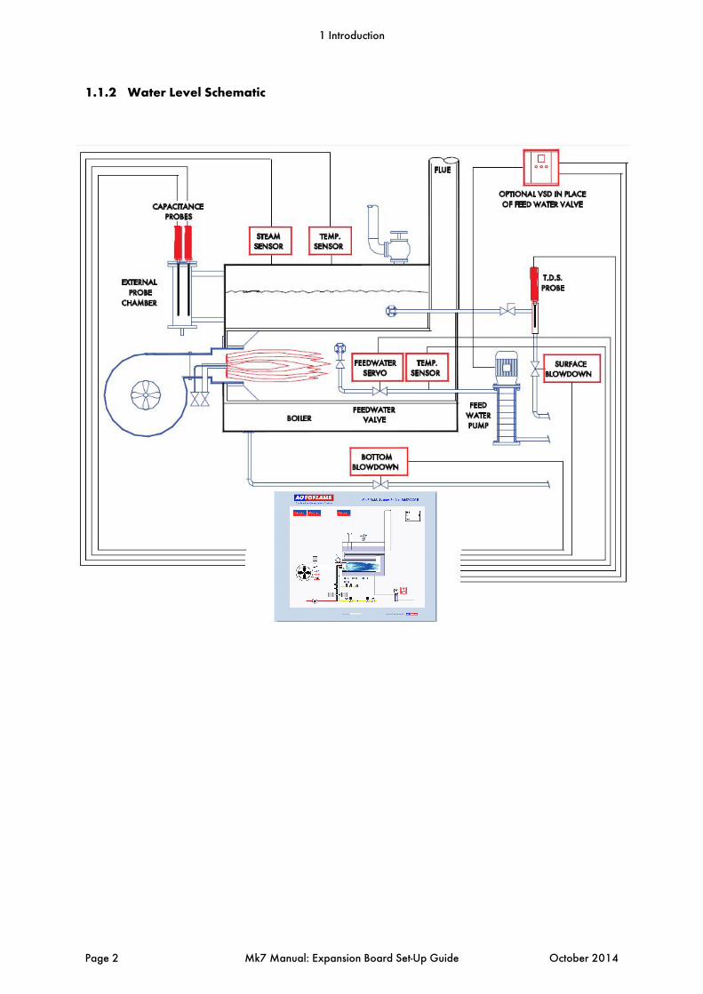
1.1.2 Water Level Schematic
1 Introduction
Page 2 Mk7 Manual: Expansion Board Set-Up Guide October 2014
1.2 Water Level Features
The Mk7 Expansion Board is used in conjunction with the Mk7 Micro-Modulation (M.M.) burner controller to report and control levels of water within industrial steam boilers. The intelligent water level control includes high water alarms, 1st low and 2nd low alarms. Alarm level reporting deals with the ability to determine whether the current water level in the boiler is above or below a predetermined level. These levels vary with each installation, and must therefore be programmed on site by a qualified commissioning engineer. Intelligent Water Level Control The feed water flow is managed by 3-element control, in response to the water level measured by the capacitance/frequency readings, boiler pressure and the burner’s firing rate. The flow is controlled by a fully modulating feed water/VSD or by using an on/off signal from a feed water pump. The Autoflame 3-element level control has been granted a worldwide patent; being the only system that can combine firing rate, steam pressure and water level within one controller for the purpose of improving feed water control. Safety, accuracy and integrity are guaranteed. The two capacitance probes control up to seven operational levels including: High high level High level Pre-high level Control point or pump on/off levels Pre-1st low level 1st low level 2nd low level End of probe level
The capacitance readings are constantly checked between both of the probes, the commissioned value and an internal hardware reference capacitor (to account for long term drift and temperature variations). Both probes have a self-checking feature for mechanical and electrical integrity. The commissioned levels by the capacitance probes have an accuracy of ± 2mm repeatability. The patented movement detection of water feature ensures that no static value can be accepted, i.e. the probes are in turbulent water. The swell management feature prevents intermittent shutdowns from the 1st low being switching due to increases in steam requirements. The Autoflame Micro-Modulation (M.M.) module knows the firing rate and boiler pressure, and accommodates for this transient condition by increasing the ‘control point’ level. The commissioning procedure for water level control, with a Mk7 M.M. unit and Mk7 Expansion Board, is extremely time-efficient and can be performed at operating pressure. It is ideal to maintain an amount of water in the boiler appropriate to the amount of steam being generated. Should the water level drop below this ideal level by an excessive amount, it is necessary to stop the burner firing. If there is insufficient water in the boiler damage may occur to its structure. In extreme cases there is the potential for the boiler to explode. The water level control herein is designed to maintain a satisfactory level of water in the boiler, whilst controlling and reporting low water level conditions.
1 Introduction
October 2014 Mk7 Manual: Expansion Board Set-Up Guide Page 3
These are the main water levels: High Water:
A high water level, although not dangerous is undesirable as water may infiltrate the steam header. If the boiler water level goes above this point the burner may or may not continue to run depending on the system configuration. If a high water level condition is detected high water audible and visual indicators are activated to notify the user. The audible indicator may be muted by means of the mute/reset push button. Pre High
A pre high level, is a pre warning before the water level reaches the high level. A visible alarm is shown. The alarm will reset once the water level is below the commissioned value. Control Point:
Ideal water level regulation point. There are no audible or visual indicators active. Pre Low
A pre low level, is a pre warning before the water level reaches 1st low. An audible and visual alarm is indicated. The alarm can be muted via the mute/reset button. The burner will not turn off; alarms will be reset once the water level is above the commissioned value. 1st Low:
A 1st low water level is a point below the control point at which the burner will turn off. If the water level falls below this point 1st low audible and visual indicators are activated. The audible indicator may be muted by means of the mute/reset push button. If the water level is restored above this point the burner will start automatically and all indicators will also be reset. 2nd Low:
A 2nd low water level is a point below 1st low at which the burner will remain off. If the water level falls below this point 2nd low audible and visual indicators are activated. The audible indicator may be muted by means of the mute/reset push button. Even if the water level is restored above this point the burner will remain off. Operator intervention is required to manually reset the system and can only be performed once the level is above the 2nd low point. The 2nd low reset condition is non-volatile - if the system is powered down the reset condition will remain when power is reapplied. In this scenario the operator reset will still be necessary. Bottom of probe:
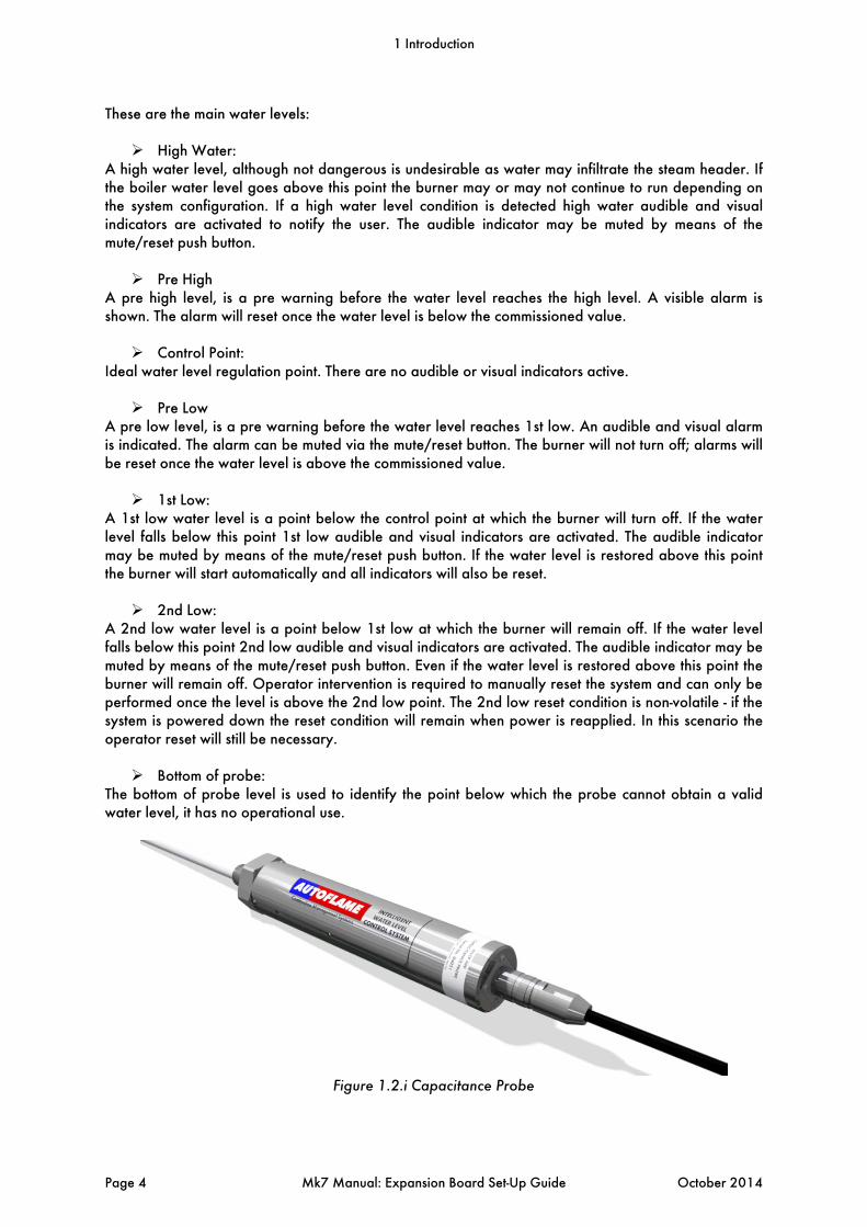
The bottom of probe level is used to identify the point below which the probe cannot obtain a valid water level, it has no operational use.
Figure 1.2.i Capacitance Probe
1 Introduction
Page 4 Mk7 Manual: Expansion Board Set-Up Guide October 2014

2 SET-UP
2.1 Expansion Board Wiring and Dimensions
2.1.1 Wiring Diagram
2 Set-Up
October 2014 Mk7 Manual: Expansion Board Set-Up Guide Page 5
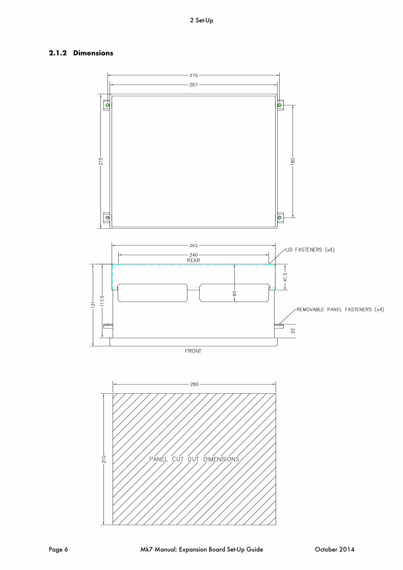
2.1.2 Dimensions
2 Set-Up
Page 6 Mk7 Manual: Expansion Board Set-Up Guide October 2014

2.1.3 Terminals Description
Note that all the “-” & P- terminals on the low voltage connection strip are common to each other, All of the circuitry associated with this terminal strip (analogue inputs and outputs) is isolated from earth potential (i.e. floating). If a VSD is used that has isolated input signal circuitry, link one of the “-” terminals to an S terminal (e.g. between P- and the adjacent S terminal to its left). If using a VSD and the VSD signal input circuitry is earthed, do NOT install a link.
ALL TERMINALS MARKED “S” ARE CONNECTED TO MAINS EARTH TERMINAL 66 ON THE MK7 M.M. AND ARE ONLY FOR CONNECTION TO CABLE SCREENS
Terminal Block 1 P- Top Bowdown and Feed water valve position potentiometer
PW Feed water valve position potentiometer
P+ Top Bowdown and Feed water valve position potentiometer
- Cold water make up and boiler steam temperature sensor
T1 Cold water make up temperature sensor
T2 Boiler steam temperature sensor
- Condensate return temperature sensor
T1A Condensate return temperature sensor
PW Top Bowdown valve position potentiometer
- Cold water make up and condensate return flow meter
MF Cold water make up flow meter
CF Condensate return flow meter
I+ Feed water VSD output
V+ Feed water VSD output
- Feed water VSD output Terminal Block 2 DPC Connections solely dedicated to the Autoflame draft pressure sensor
DPS Connections solely dedicated to the Autoflame draft pressure sensor
DP- Draft pressure sensor & motorised draft control damper voltage –ve
DP+ Draft pressure sensor & motorised draft control damper voltage +ve
DPW Motorised draft control damper potentiometer wiper
2 Set-Up
October 2014 Mk7 Manual: Expansion Board Set-Up Guide Page 7
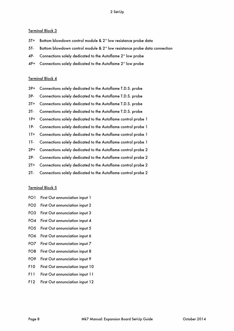
Terminal Block 3 5T+ Bottom blowdown control module & 2nd low resistance probe data
5T- Bottom blowdown control module & 2nd low resistance probe data connection
4P- Connections solely dedicated to the Autoflame 2nd low probe
4P+ Connections solely dedicated to the Autoflame 2nd low probe Terminal Block 4 3P+ Connections solely dedicated to the Autoflame T.D.S. probe
3P- Connections solely dedicated to the Autoflame T.D.S. probe
3T+ Connections solely dedicated to the Autoflame T.D.S. probe
3T- Connections solely dedicated to the Autoflame T.D.S. probe
1P+ Connections solely dedicated to the Autoflame control probe 1
1P- Connections solely dedicated to the Autoflame control probe 1
1T+ Connections solely dedicated to the Autoflame control probe 1
1T- Connections solely dedicated to the Autoflame control probe 1
2P+ Connections solely dedicated to the Autoflame control probe 2
2P- Connections solely dedicated to the Autoflame control probe 2
2T+ Connections solely dedicated to the Autoflame control probe 2
2T- Connections solely dedicated to the Autoflame control probe 2 Terminal Block 5 FO1 First Out annunciation input 1
FO2 First Out annunciation input 2
FO3 First Out annunciation input 3
FO4 First Out annunciation input 4
FO5 First Out annunciation input 5
FO6 First Out annunciation input 6
FO7 First Out annunciation input 7
FO8 First Out annunciation input 8
FO9 First Out annunciation input 9
F10 First Out annunciation input 10
F11 First Out annunciation input 11
F12 First Out annunciation input 12
2 Set-Up
Page 8 Mk7 Manual: Expansion Board Set-Up Guide October 2014
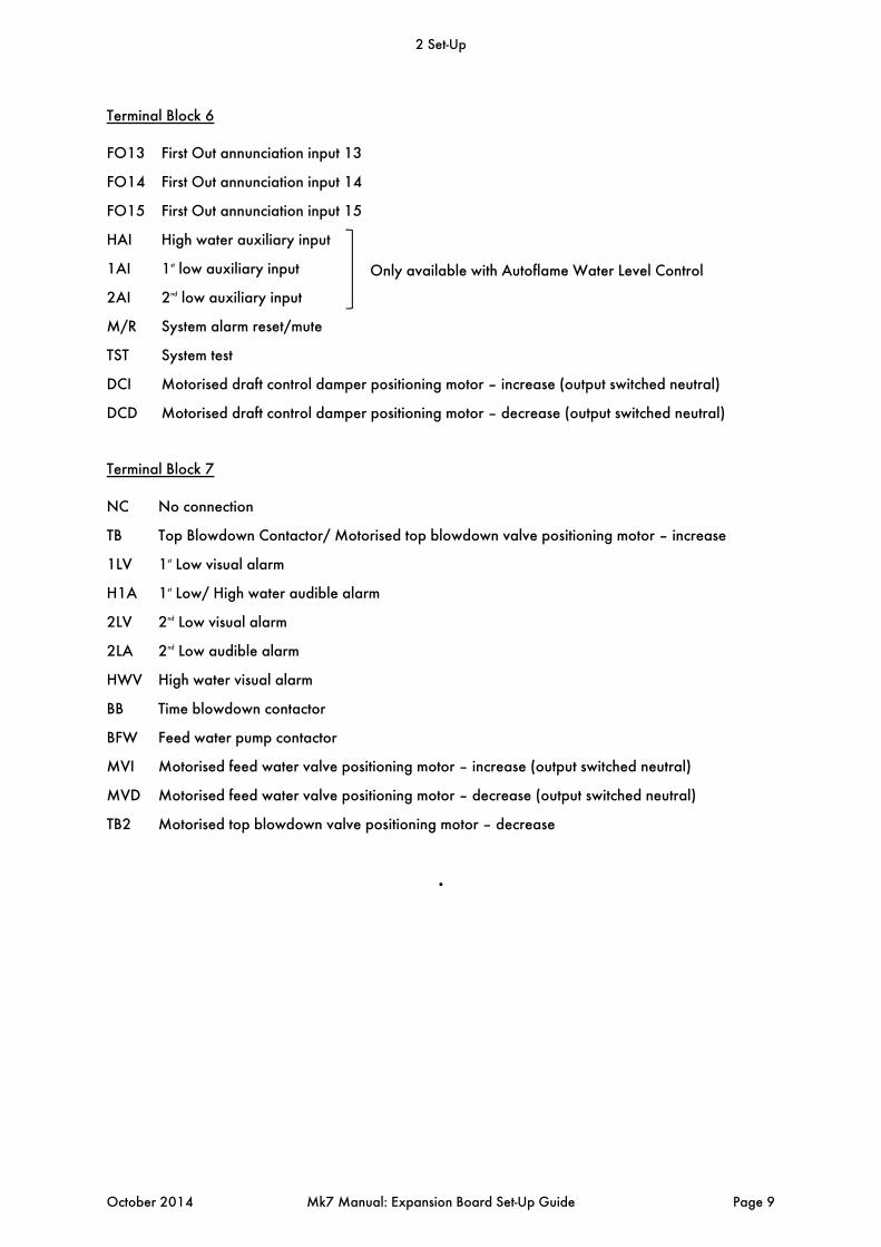
Terminal Block 6 FO13 First Out annunciation input 13
FO14 First Out annunciation input 14
FO15 First Out annunciation input 15
HAI High water auxiliary input
1AI 1st low auxiliary input
2AI 2nd low auxiliary input
M/R System alarm reset/mute
TST System test
DCI Motorised draft control damper positioning motor – increase (output switched neutral)
DCD Motorised draft control damper positioning motor – decrease (output switched neutral) Terminal Block 7 NC No connection
TB Top Blowdown Contactor/ Motorised top blowdown valve positioning motor – increase
1LV 1st Low visual alarm
H1A 1st Low/ High water audible alarm
2LV 2nd Low visual alarm
2LA 2nd Low audible alarm
HWV High water visual alarm
BB Time blowdown contactor
BFW Feed water pump contactor
MVI Motorised feed water valve positioning motor – increase (output switched neutral)
MVD Motorised feed water valve positioning motor – decrease (output switched neutral)
TB2 Motorised top blowdown valve positioning motor – decrease
.
Only available with Autoflame Water Level Control
2 Set-Up
October 2014 Mk7 Manual: Expansion Board Set-Up Guide Page 9
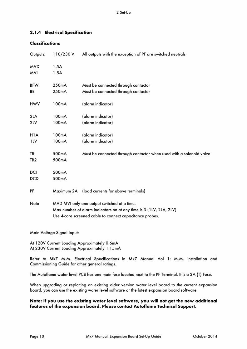
2.1.4 Electrical Specification
Classifications
Outputs: 110/230 V All outputs with the exception of PF are switched neutrals
MVD 1.5A
MVI 1.5A
BFW 250mA Must be connected through contactor
BB 250mA Must be connected through contactor
HWV 100mA (alarm indicator)
2LA 100mA (alarm indicator)
2LV 100mA (alarm indicator)
H1A 100mA (alarm indicator)
1LV 100mA (alarm indicator)
TB 500mA Must be connected through contactor when used with a solenoid valve
TB2 500mA
DCI 500mA
DCD 500mA
PF Maximum 2A (load currents for above terminals)
Note MVD MVI only one output switched at a time.
Max number of alarm indicators on at any time is 3 (1LV, 2LA, 2LV)
Use 4-core screened cable to connect capacitance probes.
Main Voltage Signal Inputs At 120V Current Loading Approximately 0.6mA At 230V Current Loading Approximately 1.15mA Refer to Mk7 M.M. Electrical Specifications in Mk7 Manual Vol 1: M.M. Installation and Commissioning Guide for other general ratings. The Autoflame water level PCB has one main fuse located next to the PF Terminal. It is a 2A (T) Fuse. When upgrading or replacing an existing older version water level board to the current expansion board, you can use the existing water level software or the latest expansion board software. Note: If you use the existing water level software, you will not get the new additional features of the expansion board. Please contact Autoflame Technical Support.
2 Set-Up
Page 10 Mk7 Manual: Expansion Board Set-Up Guide October 2014
2.2 Options
The expansion options can be changed by going to the Commission screen, entering the password and pressing on Expansion Options. These expansion options will need to be configured before commissioning the water level probes. To go into the additional water level set-ups, set M.M. parameter 109 to 1.
2 Set-Up
October 2014 Mk7 Manual: Expansion Board Set-Up Guide Page 11
Exp. O
ption
Facto
ry Setti
ng
ValueDescr
iption
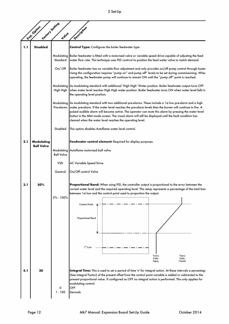
1.1 Disabled Control Type: Configures the boiler feedwater type.
Modulating Boiler feedwater is fitted with a motorised valve or variable speed drive capable of adjusting the feed
Standard water flow rate. This technique uses PID contrrol to position the feed water valve to match demand.
On/ Off Boiler feedwater has no variable flow adjustment and only provides on/off pump control through hyster
Using this configuration requires “pump on” and pump off” levels to be set during commissioning. When
operating, the feedwater pump will continue to remain ON until the “pump off” point is reached.
Modulating As modulating standard with additional ‘High High’ Water position. Boiler feedwater output turns OFF
High High when water level reaches High High water position. Boiler feedwater turns ON when water level falls to
the operating level position.
Modulating As modulating standard with two additional pre-alarms. These include a 1st low pre-alarm and a high
Pre-alarms water pre-alarm. If the water level reaches the pre-alarm levels then the burner will continue to fire. A
pulsed audible alarm will become active. The operator can mute this alarm by pressing the water level
button in the Mk6 mode screen. The visual alarm will still be displayed until the fault condition has
cleared when the water level reaches the operating level.
Disabled This option disables Autoflame water level control.
2.1 Modulating Feedwater control element: Required for display purposes.
Ball ValveModulating Autoflame motorised ball valve
Ball Valve
VSD AC Variable Speed Drive
General On/Off control Valve
3.1 50% Proportional Band: When using PID, the controller output is proportional to the error between the
current water level and the required operating level. This setup represents a percentage of the total ban
between 1st low and the control point used to proportion the output.
5% - 100%
4.1 20 Integral Time: This is used to set a period of time 'n' for integral action. At these intervals a percentage
(See Integral Factor) of the present offset from the control point variable is added or subtracted to the
present proportional value. If configured as OFF no integral action is performed. This only applies for
modulating control.
0 OFF
1 - 100 Seconds
2 Set-Up
Page 12 Mk7 Manual: Expansion Board Set-Up Guide October 2014

Exp. O
ption
Facto
ry Setti
ng
ValueDescr
iption
4.2 0.10 Integral Factor: This expansion option is used to set the percentage of the present offset from the contr
point variable to be added or subtracted from the present proportional value. This only applies for
modulating control. See also expansion options 3.1 and 4.1.
1 - 50 % (Increments of 0.01)
5.1 OFF Derivative Time: With derivative action, the controller output is proportional to the rate of change of t
water level. This expansion option controls the time interval between the controller comparing the curren
water level and the required water level points. If configured as OFF no derivative action is performed.
This only applies modulating control. See also expansion options 5.2 and 5.3.
0 OFF
1 - 100 Seconds
5.2 10% Derivative Deadband: This expansion option is used to configure the margin above and below the
required level within which there is no derivative action. This only applies for modulating control.
See also expansion options 5.1 and 5.3.
1 - 50 %
5.3 10% Derivative Response Sensitivity: This expansion option indicates the percentage of feedwater incre
or decrease that is inflicted by the derivative action. This only applies for modulating control. See also
expansion options 5.1 and 5.2.
1 - 50 %
6.1 152 Potentiometer Close Position: Servomotor potentiometer feedback at close position. This is only
required when configured for use with a motorized valve. See expansion option 6.2.
50 - 4050
6.2 2432 Potentiometer Open Position: Servomotor potentiometer feedback at open position. This is only
required when configured for use with a motorized valve. See expansion option 6.1.
7.1 3 Sudden Pressure Change - Time Between Readings: Period of seconds over which the change o
pressure is tested.
0 OFF
1 - 60 Seconds
7.2 1.5 Sudden Pressure Change - Delta Pressure (and clear band): Amount of pressure drop over tim
(specified in expansion option 7.1) that must occur for raised control point to be triggered.
1 - 50 (Increments of 0.1)
7.3 1 Sudden Pressure Change - Percent Increase Slider: Water level control point percent increase
scale. Percentage of distance between control point and High water.
0 0%
1 25%
2 50%
3 75%
7.4 1.0 Sudden Pressure Drop- Pressure Slider: Pressure scale - offset from Required value.
5 - 100 (Increments of 0.1)
8.1 RUNS Burner Operation at High Water: Sets whether the boiler should continue to run or stop when a hig
water condition exists.
RUNS
STOPS
9.1 1.00% Boiler Standing Losses: Percentage of boiler Maximum Continuous Rating, for the purpose of
steam flow metering only.
0 - 2.00 % (Increments of 0.1)
2 Set-Up
October 2014 Mk7 Manual: Expansion Board Set-Up Guide Page 13
Exp. O
ption
Facto
ry Setti
ng
ValueDescr
iption
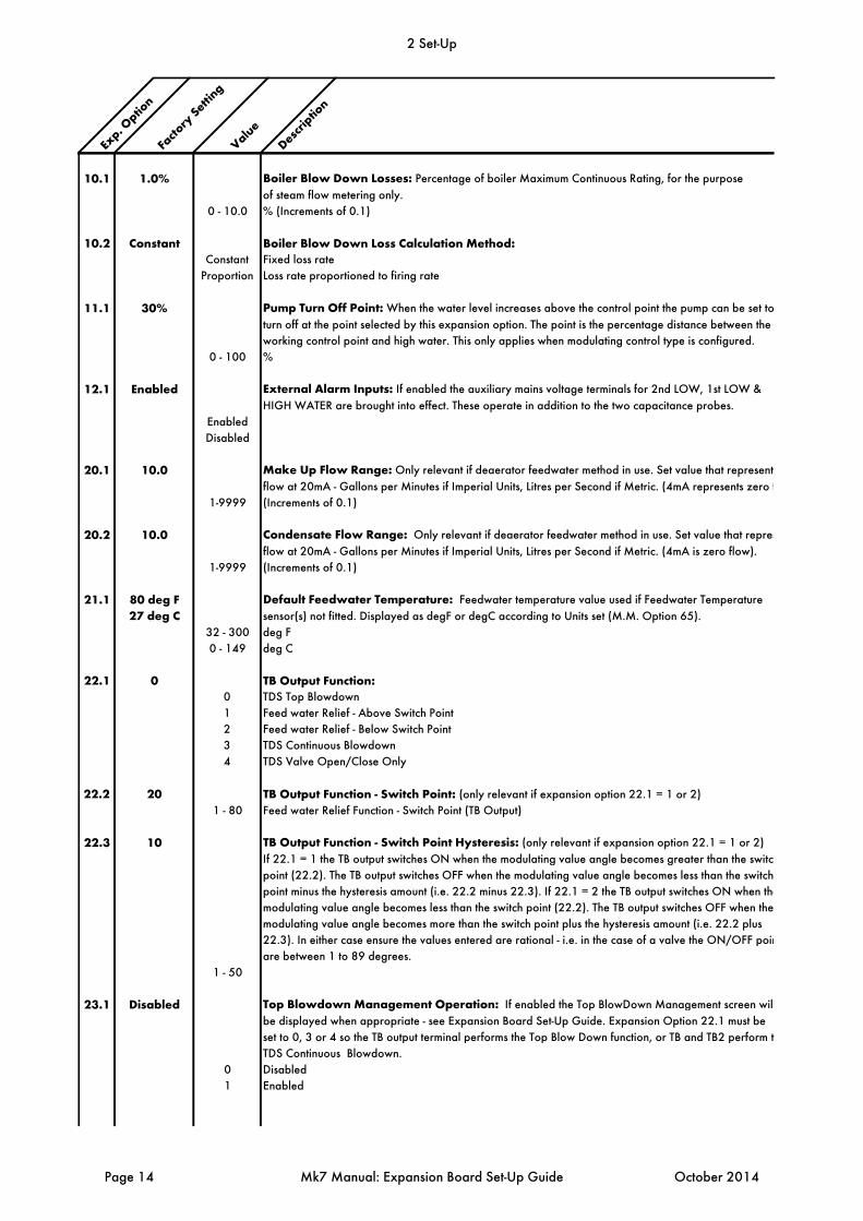
10.1 1.0% Boiler Blow Down Losses: Percentage of boiler Maximum Continuous Rating, for the purpose
of steam flow metering only.
0 - 10.0 % (Increments of 0.1)
10.2 Constant Boiler Blow Down Loss Calculation Method:Constant Fixed loss rate
Proportion Loss rate proportioned to firing rate
11.1 30% Pump Turn Off Point: When the water level increases above the control point the pump can be set to
turn off at the point selected by this expansion option. The point is the percentage distance between the
working control point and high water. This only applies when modulating control type is configured.
0 - 100 %
12.1 Enabled External Alarm Inputs: If enabled the auxiliary mains voltage terminals for 2nd LOW, 1st LOW &
HIGH WATER are brought into effect. These operate in addition to the two capacitance probes.
Enabled
Disabled
20.1 10.0 Make Up Flow Range: Only relevant if deaerator feedwater method in use. Set value that represents
flow at 20mA - Gallons per Minutes if Imperial Units, Litres per Second if Metric. (4mA represents zero f
1-9999 (Increments of 0.1)
20.2 10.0 Condensate Flow Range: Only relevant if deaerator feedwater method in use. Set value that repres
flow at 20mA - Gallons per Minutes if Imperial Units, Litres per Second if Metric. (4mA is zero flow).
1-9999 (Increments of 0.1)
21.1 80 deg F Default Feedwater Temperature: Feedwater temperature value used if Feedwater Temperature
27 deg C sensor(s) not fitted. Displayed as degF or degC according to Units set (M.M. Option 65).
32 - 300 deg F
0 - 149 deg C
22.1 0 TB Output Function:0 TDS Top Blowdown
1 Feed water Relief - Above Switch Point
2 Feed water Relief - Below Switch Point
3 TDS Continuous Blowdown
4 TDS Valve Open/Close Only
22.2 20 TB Output Function - Switch Point: (only relevant if expansion option 22.1 = 1 or 2)
1 - 80 Feed water Relief Function - Switch Point (TB Output)
22.3 10 TB Output Function - Switch Point Hysteresis: (only relevant if expansion option 22.1 = 1 or 2)
If 22.1 = 1 the TB output switches ON when the modulating value angle becomes greater than the switch
point (22.2). The TB output switches OFF when the modulating value angle becomes less than the switch
point minus the hysteresis amount (i.e. 22.2 minus 22.3). If 22.1 = 2 the TB output switches ON when the
modulating value angle becomes less than the switch point (22.2). The TB output switches OFF when the
modulating value angle becomes more than the switch point plus the hysteresis amount (i.e. 22.2 plus
22.3). In either case ensure the values entered are rational - i.e. in the case of a valve the ON/OFF poin
are between 1 to 89 degrees.
1 - 50
23.1 Disabled Top Blowdown Management Operation: If enabled the Top BlowDown Management screen will
be displayed when appropriate - see Expansion Board Set-Up Guide. Expansion Option 22.1 must be
set to 0, 3 or 4 so the TB output terminal performs the Top Blow Down function, or TB and TB2 perform t
TDS Continuous Blowdown.
0 Disabled
1 Enabled
2 Set-Up
Page 14 Mk7 Manual: Expansion Board Set-Up Guide October 2014
Exp. O
ption
Facto
ry Setti
ng
ValueDescr
iption
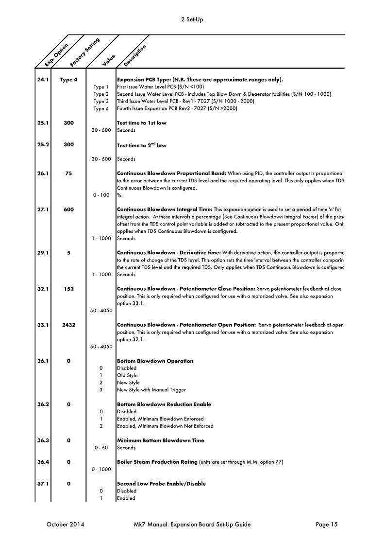
24.1 Type 4 Expansion PCB Type: (N.B. These are approximate ranges only).Type 1 First issue Water Level PCB (S/N <100)
Type 2 Second Issue Water Level PCB - includes Top Blow Down & Deaerator facilities (S/N 100 - 1000)
Type 3 Third Issue Water Level PCB - Rev1 - 7027 (S/N 1000 - 2000)
Type 4 Fourth Issue Expansion PCB Rev2 - 7027 (S/N >2000)
25.1 300 Test time to 1st low30 - 600 Seconds
25.2 300 Test time to 2nd low
30 - 600 Seconds
26.1 75 Continuous Blowdown Proportional Band: When using PID, the controller output is proportional
to the error between the current TDS level and the required operating level. This only applies when TDS
Continuous Blowdown is configured.
0 - 100 %
27.1 600 Continuous Blowdown Integral Time: This expansion option is used to set a period of time 'n' for
integral action. At these intervals a percentage (See Continuous Blowdown Integral Factor) of the prese
offset from the TDS control point variable is added or subtracted to the present proportional value. Only
applies when TDS Continuous Blowdown is configured.
1 - 1000 Seconds
29.1 5 Continuous Blowdown - Derivative time: With derivative action, the controller output is proportio
to the rate of change of the TDS level. This option sets the time interval between the controller comparing
the current TDS level and the required TDS. Only applies when TDS Continuous Blowdown is configured
1 - 1000 Seconds
32.1 152 Continuous Blowdown - Potentiometer Close Position: Servo potentiometer feedback at close
position. This is only required when configured for use with a motorized valve. See also expansion
option 33.1.
50 - 4050
33.1 2432 Continuous Blowdown - Potentiometer Open Position: Servo potentiometer feedback at open
position. This is only required when configured for use with a motorized valve. See also expansion
option 32.1.
50 - 4050
36.1 0 Bottom Blowdown Operation0 Disabled
1 Old Style
2 New Style
3 New Style with Manual Trigger
36.2 0 Bottom Blowdown Reduction Enable0 Disabled
1 Enabled, Minimum Blowdown Enforced
2 Enabled, Minimum Blowdown Not Enforced
36.3 0 Minimum Bottom Blowdown Time0 - 60 Seconds
36.4 0 Boiler Steam Production Rating (units are set through M.M. option 77)
0 - 1000
37.1 0 Second Low Probe Enable/Disable0 Disabled
1 Enabled
2 Set-Up
October 2014 Mk7 Manual: Expansion Board Set-Up Guide Page 15
Exp. O
ption
Facto
ry Setti
ng
ValueDescr
iption
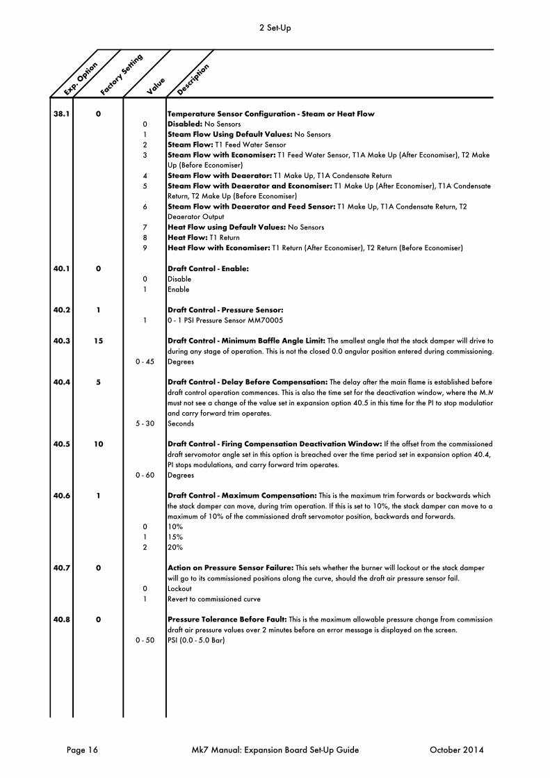
38.1 0 Temperature Sensor Configuration - Steam or Heat Flow0 Disabled: No Sensors
1 Steam Flow Using Default Values: No Sensors
2 Steam Flow: T1 Feed Water Sensor
3 Steam Flow with Economiser: T1 Feed Water Sensor, T1A Make Up (After Economiser), T2 Make
Up (Before Economiser)
4 Steam Flow with Deaerator: T1 Make Up, T1A Condensate Return
5 Steam Flow with Deaerator and Economiser: T1 Make Up (After Economiser), T1A Condensate
Return, T2 Make Up (Before Economiser)
6 Steam Flow with Deaerator and Feed Sensor: T1 Make Up, T1A Condensate Return, T2
Deaerator Output
7 Heat Flow using Default Values: No Sensors
8 Heat Flow: T1 Return
9 Heat Flow with Economiser: T1 Return (After Economiser), T2 Return (Before Economiser)
40.1 0 Draft Control - Enable:0 Disable
1 Enable
40.2 1 Draft Control - Pressure Sensor:1 0 - 1 PSI Pressure Sensor MM70005
40.3 15 Draft Control - Minimum Baffle Angle Limit: The smallest angle that the stack damper will drive to
during any stage of operation. This is not the closed 0.0 angular position entered during commissioning.
0 - 45 Degrees
40.4 5 Draft Control - Delay Before Compensation: The delay after the main flame is established before
draft control operation commences. This is also the time set for the deactivation window, where the M.M
must not see a change of the value set in expansion option 40.5 in this time for the PI to stop modulation
and carry forward trim operates.
5 - 30 Seconds
40.5 10 Draft Control - Firing Compensation Deactivation Window: If the offset from the commissioned
draft servomotor angle set in this option is breached over the time period set in expansion option 40.4,
PI stops modulations, and carry forward trim operates.
0 - 60 Degrees
40.6 1 Draft Control - Maximum Compensation: This is the maximum trim forwards or backwards which
the stack damper can move, during trim operation. If this is set to 10%, the stack damper can move to a
maximum of 10% of the commissioned draft servomotor position, backwards and forwards.
0 10%
1 15%
2 20%
40.7 0 Action on Pressure Sensor Failure: This sets whether the burner will lockout or the stack damper
will go to its commissioned positions along the curve, should the draft air pressure sensor fail.
0 Lockout
1 Revert to commissioned curve
40.8 0 Pressure Tolerance Before Fault: This is the maximum allowable pressure change from commissione
draft air pressure values over 2 minutes before an error message is displayed on the screen.
0 - 50 PSI (0.0 - 5.0 Bar)
2 Set-Up
Page 16 Mk7 Manual: Expansion Board Set-Up Guide October 2014
Exp. O
ption
Facto
ry Setti
ng
ValueDescr
iption
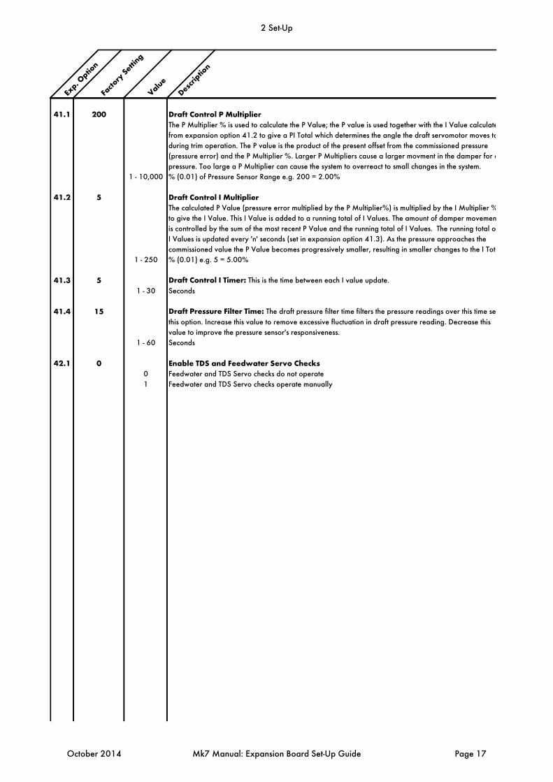
41.1 200 Draft Control P MultiplierThe P Multiplier % is used to calculate the P Value; the P value is used together with the I Value calculate
from expansion option 41.2 to give a PI Total which determines the angle the draft servomotor moves to
during trim operation. The P value is the product of the present offset from the commissioned pressure
(pressure error) and the P Multiplier %. Larger P Multipliers cause a larger movment in the damper for a
pressure. Too large a P Multiplier can cause the system to overreact to small changes in the system.
1 - 10,000 % (0.01) of Pressure Sensor Range e.g. 200 = 2.00%
41.2 5 Draft Control I MultiplierThe calculated P Value (pressure error multiplied by the P Multiplier%) is multiplied by the I Multiplier %
to give the I Value. This I Value is added to a running total of I Values. The amount of damper movemen
is controlled by the sum of the most recent P Value and the running total of I Values. The running total of
I Values is updated every 'n' seconds (set in expansion option 41.3). As the pressure approaches the
commissioned value the P Value becomes progressively smaller, resulting in smaller changes to the I Tota
1 - 250 % (0.01) e.g. 5 = 5.00%
41.3 5 Draft Control I Timer: This is the time between each I value update.
1 - 30 Seconds
41.4 15 Draft Pressure Filter Time: The draft pressure filter time filters the pressure readings over this time set
this option. Increase this value to remove excessive fluctuation in draft pressure reading. Decrease this
value to improve the pressure sensor's responsiveness.
1 - 60 Seconds
42.1 0 Enable TDS and Feedwater Servo Checks0 Feedwater and TDS Servo checks do not operate
1 Feedwater and TDS Servo checks operate manually
2 Set-Up
October 2014 Mk7 Manual: Expansion Board Set-Up Guide Page 17

Exp. O
ption
Facto
ry Setti
ng
ValueDescr
iption
A.1 10 Probe Filtering Time: Every second each probe takes 10 readings. This is then averaged over the
value set in this expansion option.
1 - 20 Seconds
B.1 5 Control Element Update Time: This is how often the modulating feedwater valve will be moved in
response to variations in the water level.
1 - 100 Seconds
C.1 2.0% Control Point Deadband: No modulation occurs within this deadband.
0 Off
1 - 200 0.1 - 20.0% (Increments of 0.1)
D.1 5 Peak to Peak Sampling Period: Highest/ lowest.
1 - 10 Seconds
D.2 1 Peak to Peak Update Time:1 - 20 Seconds
E.1 1500 Minimum Mismatch: Probe 1 is used as the reference based on the commissioing data. This probe
assesses the value of probe 2 to establish if there is a mismatch present (outside this set value). Mismatch
is a serious problem and is safety critical. If a probe mismatch occurs the probes may need cleaning.
0 - 2000 Hz (1500Hz = 3" or 75mm)
E.2 0 Maximum Mismatch: 0 - 2000 Hz
E.3 1.5 Mismatch Multiplier:10 - 100 1.0 - 10.0 (Increments of 0.1)
E.4 30 Mismatch Time: If the mismatch exceeds 30 seconds then the system will shut down. If the value of
probe 2 moves back inside the 1500 window then this timer is reset. 1st low takes priority over mistmatch.
1 - 200 Seconds
F.1 0.5 Turbulence Factor: The value set in this expansion option corresponds to the predicted water level.
0 - 25 0.0 - 2.5 (Increments of 0.1)
G.1 0 Expansion Offset:0 - 100 %
G.2 10 Expansion Turbulence Time:0 - 50 Seconds
G.3 10 Expansion Turbulence Amount:1 - 100
H.1 1 Control Point Method: 0 Probe 1: Works off the readings from probe 1 only - checks are still made between both probes.
1 Averaged: Averages the data between both probes.
J.1 1 Detect Turbulence Level:0 Disabled
1 - 100 mm. Non-movement detection: If the water is still, the frequency will drop below 10Hz and a fault occurs.
J.2 10 Detect Turbulence Time:1 - 100 Seconds
Note: If expansion option J.1 is set to 0, then this function is disabled.
2 Set-Up
Page 18 Mk7 Manual: Expansion Board Set-Up Guide October 2014
Exp. O
ption
Facto
ry Setti
ng
ValueDescr
iption
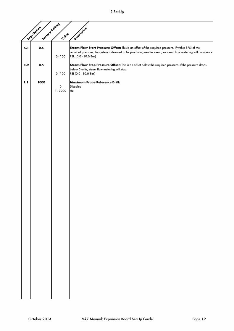
K.1 0.5 Steam Flow Start Pressure Offset: This is an offset of the required pressure. If within 5PSI of the
required pressure, the system is deemed to be producing usable steam, so steam flow metering will commence.
0 - 100 PSI. (0.0 - 10.0 Bar)
K.2 0.5 Steam Flow Stop Pressure Offset: This is an offset below the required pressure. If the pressure drops
below 5 units, steam flow metering will stop.
0 - 100 PSI (0.0 - 10.0 Bar)
L.1 1000 Maximum Probe Reference Drift:0 Disabled
1 - 3000 Hz
2 Set-Up
October 2014 Mk7 Manual: Expansion Board Set-Up Guide Page 19

2.3 Commissioning Water Level
2.3.1 Commissioning Procedure
When commissioning a burner with Autoflame water level cotnrol, the water level probes must be commissioned initially before the combustion curve is put in. Once the burner is commissioned with the Mk7 M.M., the water level probes will need to be recommissioned once the boiler is up to pressure, and water in the boiler is hot enough. If the water level control is optioned, the M.M. will be in error and cannot be commissioned until the probes have been set-up. Go into Commission mode when the system starts up and enter the password.
Figure 2.3.1.i Password Screen
2 Set-Up
Page 20 Mk7 Manual: Expansion Board Set-Up Guide October 2014
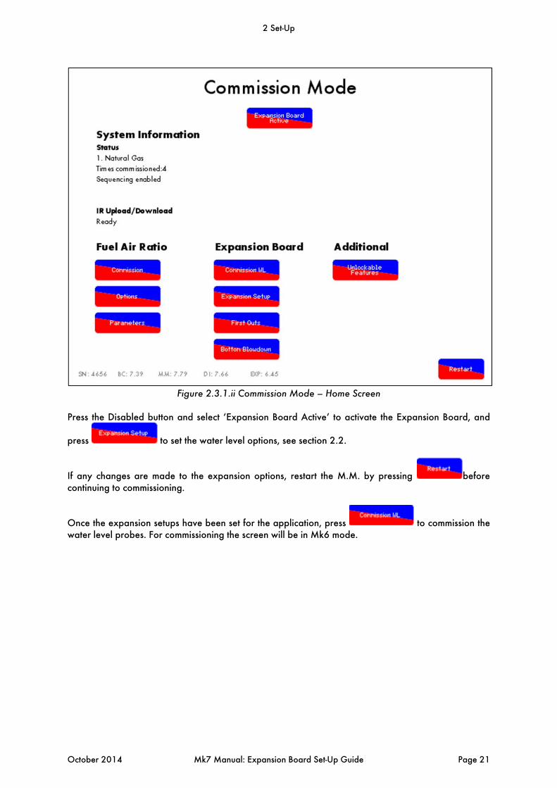
Figure 2.3.1.ii Commission Mode – Home Screen
Press the Disabled button and select ‘Expansion Board Active’ to activate the Expansion Board, and
press to set the water level options, see section 2.2.
If any changes are made to the expansion options, restart the M.M. by pressing before continuing to commissioning.
Once the expansion setups have been set for the application, press to commission the water level probes. For commissioning the screen will be in Mk6 mode.
2 Set-Up
October 2014 Mk7 Manual: Expansion Board Set-Up Guide Page 21
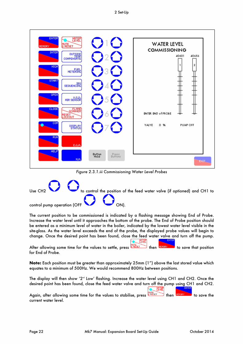
Figure 2.3.1.iii Commissioning Water Level Probes
Use CH2 to control the position of the feed water valve (if optioned) and CH1 to
control pump operation (OFF ON). The current position to be commissioned is indicated by a flashing message showing End of Probe. Increase the water level until it approaches the bottom of the probe. The End of Probe position should be entered as a minimum level of water in the boiler, indicated by the lowest water level visible in the site-glass. As the water level exceeds the end of the probe, the displayed probe values will begin to change. Once the desired point has been found, close the feed water valve and turn off the pump.
After allowing some time for the values to settle, press then to save that position for End of Probe. Note: Each position must be greater than approximately 25mm (1”) above the last stored value which equates to a minimum of 500Hz. We would recommend 800Hz between positions. The display will then show ‘2nd Low’ flashing. Increase the water level using CH1 and CH2. Once the desired point has been found, close the feed water valve and turn off the pump using CH1 and CH2.
Again, after allowing some time for the values to stabilise, press then to save the current water level.
2 Set-Up
Page 22 Mk7 Manual: Expansion Board Set-Up Guide October 2014
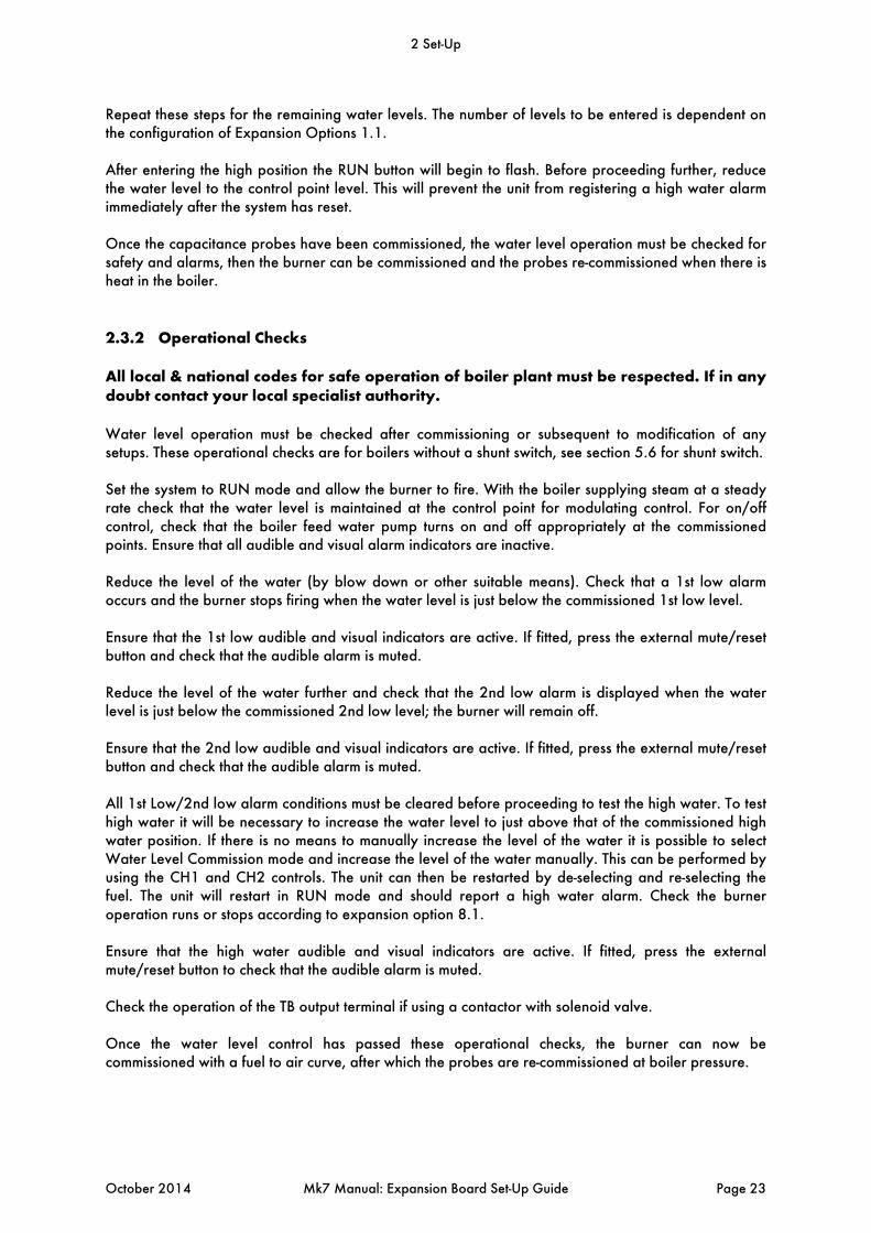
Repeat these steps for the remaining water levels. The number of levels to be entered is dependent on the configuration of Expansion Options 1.1. After entering the high position the RUN button will begin to flash. Before proceeding further, reduce the water level to the control point level. This will prevent the unit from registering a high water alarm immediately after the system has reset. Once the capacitance probes have been commissioned, the water level operation must be checked for safety and alarms, then the burner can be commissioned and the probes re-commissioned when there is heat in the boiler.
2.3.2 Operational Checks
All local & national codes for safe operation of boiler plant must be respected. If in any doubt contact your local specialist authority. Water level operation must be checked after commissioning or subsequent to modification of any setups. These operational checks are for boilers without a shunt switch, see section 5.6 for shunt switch. Set the system to RUN mode and allow the burner to fire. With the boiler supplying steam at a steady rate check that the water level is maintained at the control point for modulating control. For on/off control, check that the boiler feed water pump turns on and off appropriately at the commissioned points. Ensure that all audible and visual alarm indicators are inactive. Reduce the level of the water (by blow down or other suitable means). Check that a 1st low alarm occurs and the burner stops firing when the water level is just below the commissioned 1st low level. Ensure that the 1st low audible and visual indicators are active. If fitted, press the external mute/reset button and check that the audible alarm is muted. Reduce the level of the water further and check that the 2nd low alarm is displayed when the water level is just below the commissioned 2nd low level; the burner will remain off. Ensure that the 2nd low audible and visual indicators are active. If fitted, press the external mute/reset button and check that the audible alarm is muted. All 1st Low/2nd low alarm conditions must be cleared before proceeding to test the high water. To test high water it will be necessary to increase the water level to just above that of the commissioned high water position. If there is no means to manually increase the level of the water it is possible to select Water Level Commission mode and increase the level of the water manually. This can be performed by using the CH1 and CH2 controls. The unit can then be restarted by de-selecting and re-selecting the fuel. The unit will restart in RUN mode and should report a high water alarm. Check the burner operation runs or stops according to expansion option 8.1. Ensure that the high water audible and visual indicators are active. If fitted, press the external mute/reset button to check that the audible alarm is muted. Check the operation of the TB output terminal if using a contactor with solenoid valve. Once the water level control has passed these operational checks, the burner can now be commissioned with a fuel to air curve, after which the probes are re-commissioned at boiler pressure.
2 Set-Up
October 2014 Mk7 Manual: Expansion Board Set-Up Guide Page 23
2.4 First Outs Set-Up
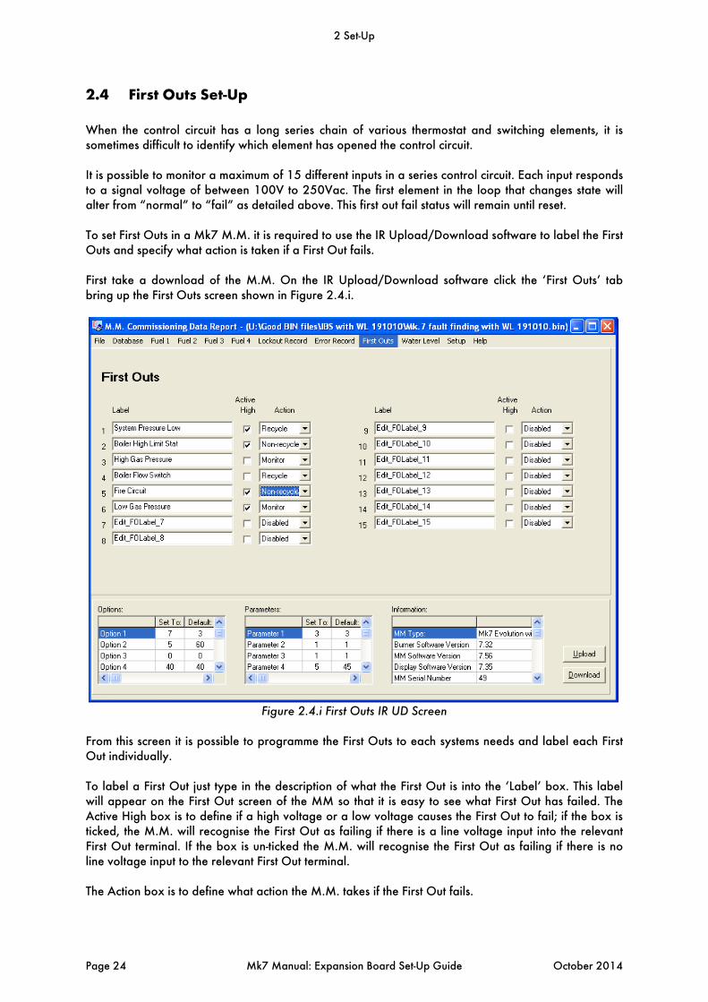
When the control circuit has a long series chain of various thermostat and switching elements, it is sometimes difficult to identify which element has opened the control circuit. It is possible to monitor a maximum of 15 different inputs in a series control circuit. Each input responds to a signal voltage of between 100V to 250Vac. The first element in the loop that changes state will alter from “normal” to “fail” as detailed above. This first out fail status will remain until reset. To set First Outs in a Mk7 M.M. it is required to use the IR Upload/Download software to label the First Outs and specify what action is taken if a First Out fails. First take a download of the M.M. On the IR Upload/Download software click the ‘First Outs’ tab bring up the First Outs screen shown in Figure 2.4.i.
Figure 2.4.i First Outs IR UD Screen
From this screen it is possible to programme the First Outs to each systems needs and label each First Out individually. To label a First Out just type in the description of what the First Out is into the ‘Label’ box. This label will appear on the First Out screen of the MM so that it is easy to see what First Out has failed. The Active High box is to define if a high voltage or a low voltage causes the First Out to fail; if the box is ticked, the M.M. will recognise the First Out as failing if there is a line voltage input into the relevant First Out terminal. If the box is un-ticked the M.M. will recognise the First Out as failing if there is no line voltage input to the relevant First Out terminal. The Action box is to define what action the M.M. takes if the First Out fails.
2 Set-Up
Page 24 Mk7 Manual: Expansion Board Set-Up Guide October 2014
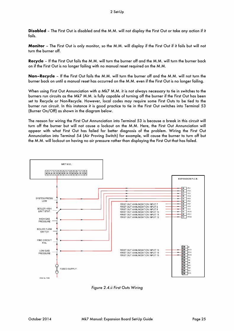
Disabled – The First Out is disabled and the M.M. will not display the First Out or take any action if it fails. Monitor – The First Out is only monitor, so the M.M. will display if the First Out if it fails but will not turn the burner off. Recycle – If the First Out fails the M.M. will turn the burner off and the M.M. will turn the burner back on if the First Out is no longer failing with no manual reset required on the M.M. Non–Recycle – If the First Out fails the M.M. will turn the burner off and the M.M. will not turn the burner back on until a manual reset has occurred on the M.M. even if the First Out is no longer failing. When using First Out Annunciation with a Mk7 M.M. it is not always necessary to tie in switches to the burners run circuits as the Mk7 M.M. is fully capable of turning off the burner if the First Out has been set to Recycle or Non-Recycle. However, local codes may require some First Outs to be tied to the burner run circuit. In this instance it is good practice to tie in the First Out switches into Terminal 53 (Burner On/Off) as shown in the diagram below. The reason for wiring the First Out Annunciation into Terminal 53 is because a break in this circuit will turn off the burner but will not cause a lockout on the M.M. Here, the First Out Annunciation will appear with what First Out has failed for better diagnosis of the problem. Wiring the First Out Annunciation into Terminal 54 (Air Proving Switch) for example, will cause the burner to turn off but the M.M. will lockout on having no air pressure rather than displaying the First Out that has failed.
Figure 2.4.ii First Outs Wiring
2 Set-Up
October 2014 Mk7 Manual: Expansion Board Set-Up Guide Page 25

2.5 Integrating Other Water Level Controls with Autoflame
It is possible to retain the site’s existing float type level controls. Autoflame have allocated 3 terminals to accommodate “high”, “1st low” and “2nd low”. This is a user selectable facility which can be accessed by the expansion options. Shown below is the connection schematic which shows how this can be implemented if required.
Figure 2.5.i External Water Level
Note: If any of the three inputs are not being used, a line voltage should be inputted to stop the unit alarming.
2 Set-Up
Page 26 Mk7 Manual: Expansion Board Set-Up Guide October 2014

3 WATER LEVEL PROBES
3.1 Breaking Bubbles/Spray
Breaking bubbles/spray refers to the bubbles of steam breaking at the boiler water level surface. These precipitate little droplets as spray several inches above the water surface in an upwards direction.
The droplets tend to coat the surface of the level probe which in turn will read as an increase in the water level. This situation is largely avoided by fitting anti surge pots inside the boiler shell. When the probes are fitted externally to the boiler shell this situation can not arise.
3.1.1 Thermal Currents (heat energy in water)
Many bubbles breaking simultaneously and thermal currents from the furnace tube and 2nd, 3rd, 4th pass smoke tube create their own turbulence/wave signature on the surface of the water. The typical result is short choppy/peaky wave patterns as below.
A second set of turbulence is the wave reflections off the sides of the boiler. The whole of the above is largely attenuated away by mounting the probes externally to the main boiler shell in a separate pot or pots.
3 Water Level Probes
October 2014 Mk7 Manual: Expansion Board Set-Up Guide Page 27

3.1.2 Steam Flow Induced Surge
When the boiler is producing high quantities of steam, this steam travels over the surface and can produce swells and surging motions (long wave).
The above situation will be shown in high relief when the steam outlet is at one end of the boiler and one level probe is sited adjacent to the steam outlet and the second probe is sited at the opposite end of the boiler. The user adjustable probe disparity value may have to be increased to take this situation into account. 3.1.3 Foaming
Foaming on the surface of the boiler is brought about by a less than adequate blow down regime and/or not controlling and managing TDS in the appropriate manner. Incorrect or insufficient water treatment will exacerbate all of the above. Foaming will read as a step increase in water level. This situation should only ever occur in a badly managed boiler plant. It can be seen from the above examples that wave signature will tend to be very installation specific. It is driven by boiler size, water treatment regime, position of heat transfer surface relative to water level and the load pattern imposed on boiler. The Autoflame system takes into account all of these variables and uses them to create a control algorithm that produces perfect level control with absolute safety.
3 Water Level Probes
Page 28 Mk7 Manual: Expansion Board Set-Up Guide October 2014
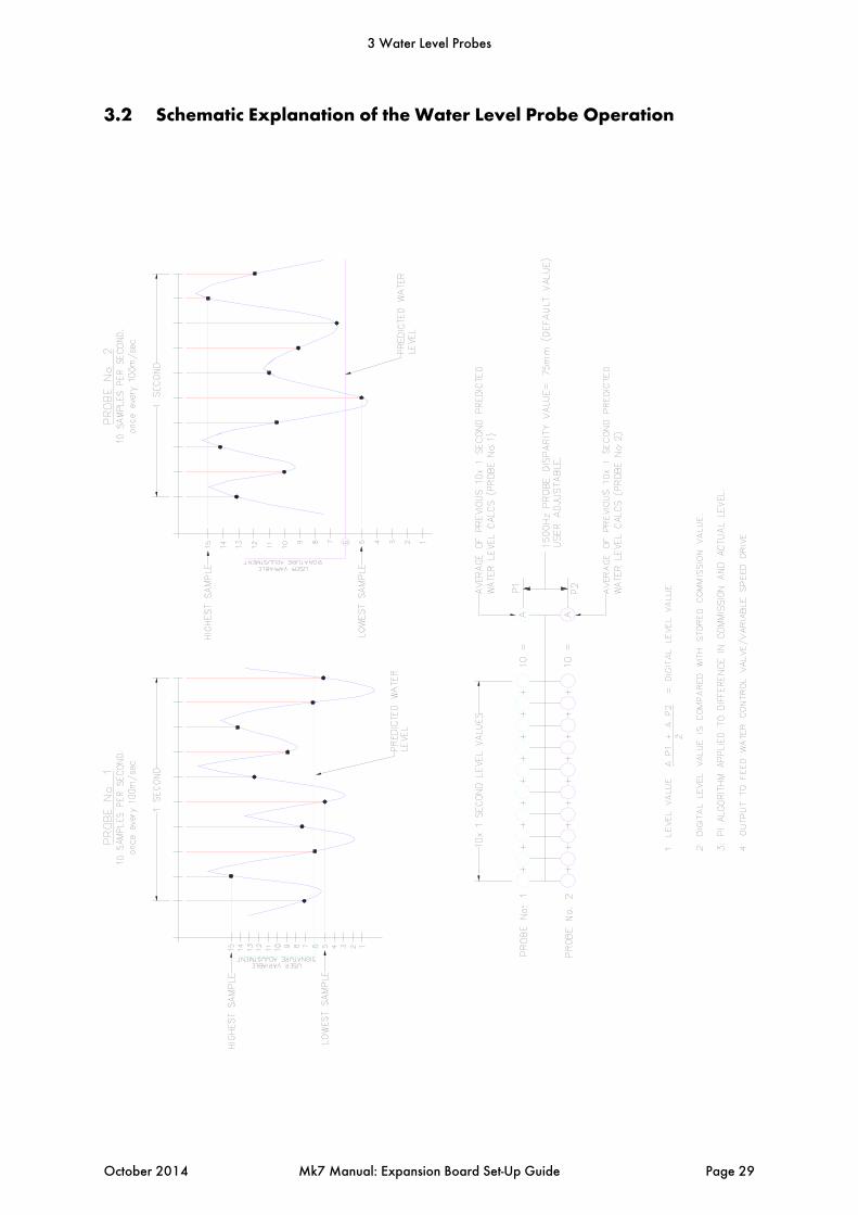
3.2 Schematic Explanation of the Water Level Probe Operation
3 Water Level Probes
October 2014 Mk7 Manual: Expansion Board Set-Up Guide Page 29
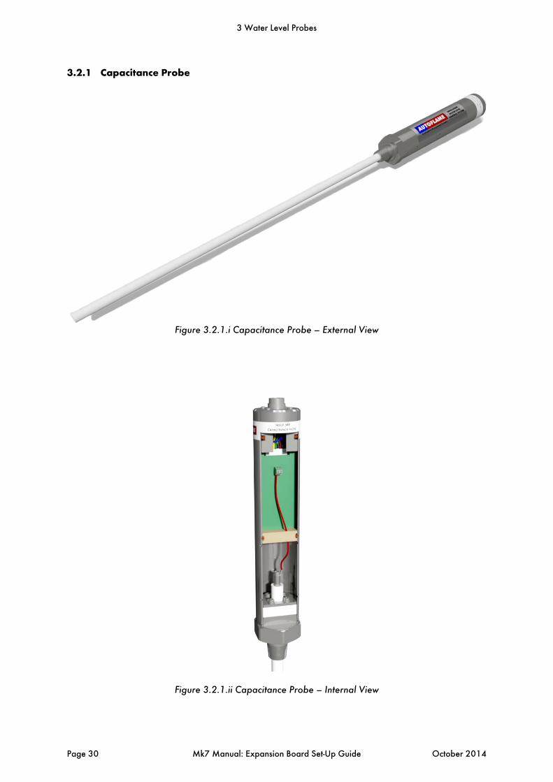
3.2.1 Capacitance Probe
Figure 3.2.1.i Capacitance Probe – External View
Figure 3.2.1.ii Capacitance Probe – Internal View
3 Water Level Probes
Page 30 Mk7 Manual: Expansion Board Set-Up Guide October 2014

3.3 Schematic of the Probe Sampling Software
3 Water Level Probes
October 2014 Mk7 Manual: Expansion Board Set-Up Guide Page 31

*IMPORTANT NOTE: THE NOTES AND MECHANICAL EXECUTIONS IMPLICIT IN THESE
DRAWINGS ARE FOR GUIDANCE PURPOSES ONLY. LOCAL, NATIONAL AND STATE
CODES MUST BE ADHERED TO IN ALL CASES. IT IS IMPORTANT TO USE ONLY
QUALIFIED AND EXPERIENCED INSTALLATION PERSONNEL. AUTOFLAME TECH
CENTRES CAN ADVISE.
UNDER ALL CODES THAT AUTOFLAME ARE AWAR OF, IT IS NOT PERMITTED TO FIT 2
PROBES IN ON EXTERNAL POT.
IF IN DOUBT, PLEASE CONTACT AUTOFLAME.
LEVEL PROBES MOUNTED EXTERNALLY
IN PURPOSED DESIGNED POTS
NON-RETURN
VALVE
AUTOFLAME FEED WATER VALVE CONTROLLED
BY A SERVOMOTOR (OPERATIONAL V.S.D.)
FEED WATER PUMP
AUTOFLAME FEED WATER
TEMP. SENSOR (PT1000)
CAPACITANCE PROBE
OPTIONAL V.S.D. CONTROL
FOR FEED WATER PUMP
FLUE
SAFETY VALVEAUTOFLAME
PRESSURE
DETECTOR
BOILER HIGH
LIMIT
STEAM NON-RETURN VALVE
STEAM FLOW VALVE/ CROWN VALVE
CAPACITANCE PROBE
AUTOFLAME STEAM TEMP. SENSOR
STEAM BOILER
SIGHT GLASS
HIGH WATER
REQUIRED LEVEL
1st LOW WATER
2nd LOW WATER
3.4 Capacitance Probe – Externally Mounted Pots
3 Water Level Probes
Page 32 Mk7 Manual: Expansion Board Set-Up Guide October 2014
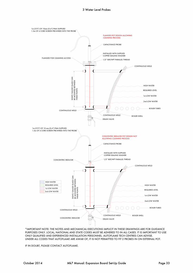
*IMPORTANT NOTE: THE NOTES AND MECHANICAL EXECUTIONS IMPLICIT IN THESE DRAWINGS ARE FOR GUIDANCE
PURPOSES ONLY. LOCAL, NATIONAL AND STATE CODES MUST BE ADHERED TO IN ALL CASES. IT IS IMPORTANT TO USE
ONLY QUALIFIED AND EXPERIENCED INSTALLATION PERSONNEL. AUTOFLAME TECH CENTRES CAN ADVISE.
UNDER ALL CODES THAT AUTOFLAME ARE AWAR OF, IT IS NOT PERMITTED TO FIT 2 PROBES IN ON EXTERNAL POT.
IF IN DOUBT, PLEASE CONTACT AUTOFLAME.
HIGH WATER
REQUIRED LEVEL
1st LOW WATER
2nd LOW WATER
CONCENTRIC REDUCER
CONTINUOUS WELD
DRAIN VALVE
CONTINUOUS WELD BOILER SHELL
BOILER TUBES
CONTINUOUS WELD
1/2” BSP/NPT PARALLEL THREAD
INSTALLED WITH SUPPLIED
COPPER SEALING WASHER
CAPACITANCE PROBE
CONCENTRIC REDUCER
1m (3’0”) OF 10 mm (0.4”) PMA SUPPLIED
1.5m OF 4 CORE SCREEN PRE-WIRED INTO THE PROBE
CONTINUOUS WELD
DRAIN VALVE
CONTINUOUS WELD BOILER SHELL
BOILER TUBES
HIGH WATER
REQUIRED LEVEL
1st LOW WATER
2nd LOW WATER
HIGH WATER
REQUIRED LEVEL
1st LOW WATER
2nd LOW WATER
CONCENTRIC REDUCER POT DESIGN NOT
ALLOWING CLEANING PROCESS
CONTINUOUS WELD
CAPACITANCE PROBE
INSTALLED WITH SUPPLIED
COPPER SEALING WASHER
1/2” BSP/NPT PARALLEL THREADFLANGED FOR CLEANING ACCESS
1m (3’0”) OF 10mm (0.4”) PMA SUPPLIED
1.5m OF 4 CORE SCREEN PRE-WIRED INTO THE PROBE
SIG
HT/
GA
UG
E G
LAS
S C
AN
BE M
OU
NTE
D B
ETW
EEN
THES
E P
OIN
TS
SIG
HT/
GA
UG
E G
LAS
S C
AN
BE M
OU
NTE
D B
ETW
EEN
THES
E P
OIN
TS
FLANGED POT DESIGN ALLOWING
CLEANING PROCESS
3 Water Level Probes
October 2014 Mk7 Manual: Expansion Board Set-Up Guide Page 33

*IMPORTANT NOTE: THE NOTES AND MECHANICAL EXECUTIONS IMPLICIT IN THESE DRAWINGS ARE FOR
GUIDANCE PURPOSES ONLY. LOCAL, NATIONAL AND STATE CODES MUST BE ADHERED TO IN ALL CASES.
IT IS IMPORTANT TO USE ONLY QUALIFIED AND EXPERIENCED INSTALLATION PERSONNEL. AUTOFLAME
TECH CENTRES CAN ADVISE.
IF IN DOUBT, PLEASE CONTACT AUTOFLAME.
HIGH WATER
REQUIRED LEVEL
1st LOW WATER
2nd LOW WATER
LEVEL PROBES INSTALLED DIRECTLY TO BOILER SHELL
NON-RETURN
VALVE
STEAM BOILER
SIGHT GLASS
AUTOFLAME FEED WATER VALVE CONTROLLED
BY A SERVOMOTOR (OPTIONAL V.S.D.)
FEED WATER PUMP
ISOLATION VALVE
AUTOFLAME FEED WATER
TEMP. SENSOR (PT1000)
OPTIONAL V.S.D. CONTROL
FOR FEED WATER PUMP
FLUE
SAFETY VALVECAPACITANCE
PROBES
STEAM NON-RETURN VALVE
STEAM FLOW VALVE/ CROWN VALVE
AUTOFLAME STEAM TEMP. SENSOR
3.5 Capacitance Probe – Internally Mounted Pots
3 Water Level Probes
Page 34 Mk7 Manual: Expansion Board Set-Up Guide October 2014

*IMPORTANT NOTE: THE NOTES AND MECHANICAL EXECUTIONS IMPLICIT IN THESE DRAWINGS ARE FOR GUIDANCE
PURPOSES ONLY. LOCAL, NATIONAL AND STATE CODES MUST BE ADHERED TO IN ALL CASES. IT IS IMPORTANT TO
USE ONLY QUALIFIED AND EXPERIENCED INSTALLATION PERSONNEL. AUTOFLAME TECH CENTRES CAN ADVISE.
IF IN DOUBT, PLEASE CONTACT AUTOFLAME.
HIGH WATER
REQUIRED LEVEL
1st LOW WATER
2nd LOW WATER
BOILER TUBES
2off 18mm x 120mm SLOTS
BOTTOM 1” OF THE PROBE IS THE
SEALING PLUG AND WILL NOT
GIVE A CAPACITANCE READING
RECOMMENDED MINIMUM 6” PIPE I.D.
10x 24mm HOLES EQUSPACED AROUND 6” PIPE
BOILER SHELL
1m (3’0”) OF 10mm (0.4”) PMA SUPPLIED
1.5m OF 4 CORE SCREEN PRE-WIRED INTO THE PROBE
CAPACITANCE PROBES
INSTALLED WITH COPPER
SEALING WASHER
1/2” BSP/NPT PARALLEL THREAD
RECOMMENDED
MINIMUM 6” PIPE TAPPING DETAIL
TAPPED 1/2” BSP
1/2
” C
LEA
RA
NC
E F
RO
M E
ND
OF
PR
OB
E S
HR
OU
D
1”
OF
CLE
AR
AN
CE
AB
OV
E B
OIL
ER
TU
BE
S
LEVEL PROBES MOUNTED DIRECTLY TO
BOILER SHELL (TOGETHER)
18mm WIDE SLOT BOTH SIDES
9mm WIDE SLOT BOTH SIDES
BOILER TUBES
2off 9mm x 67mm SLOTS
BOTTOM 1” OF THE PROBE IS THE
SEALING PLUG AND WILL NOT GIVE
A CAPACITANCE READING
RECOMMENDED MINIMUM 3” PIPE I.D.
10 x 12mm HOLES EQUISPACED AROUND 3” PIPE
BOILER SHELL
1m (3’0”) OF 10mm (0.4”) PMA SUPPLIED
1.5m OF 4 CORE SCREEN PRE-WIRED INTO THE PROBE
CAPACITANCE PROBE
INSTALLED WITH SUPPLIED
COPPER SEALING WASHER
1/2” BSP/NPT PARALLEL THREAD
1/2
” C
LEA
RA
NC
E F
RO
M E
ND
OF
PR
OB
E S
HR
OU
D
1”
OF
CLE
AR
AN
CE
AB
OV
E B
OIL
ER
TU
BE
S
3 Water Level Probes
October 2014 Mk7 Manual: Expansion Board Set-Up Guide Page 35
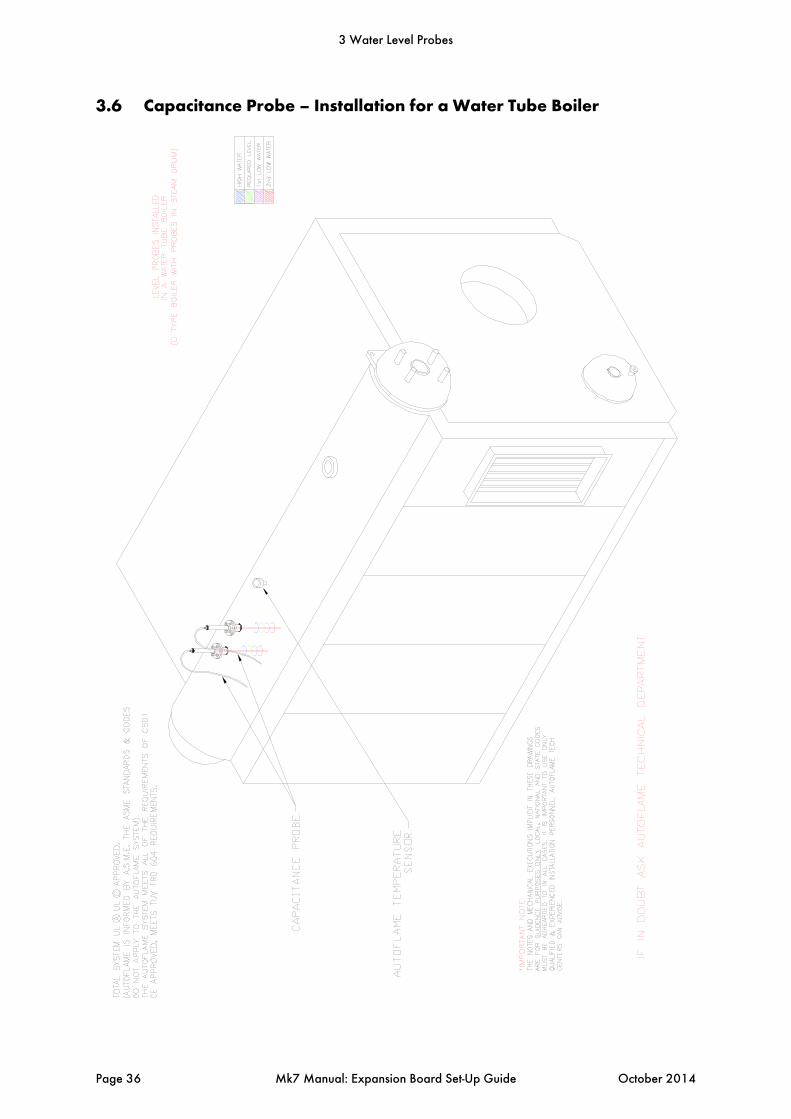
3.6 Capacitance Probe – Installation for a Water Tube Boiler
3 Water Level Probes
Page 36 Mk7 Manual: Expansion Board Set-Up Guide October 2014
3 Water Level Probes
October 2014 Mk7 Manual: Expansion Board Set-Up Guide Page 37
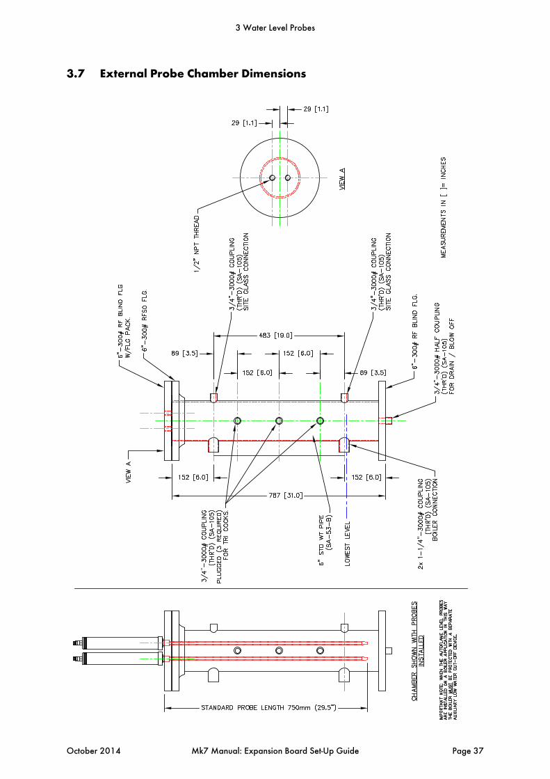
3.7 External Probe Chamber Dimensions
3.8 Capacitance Probe Specification
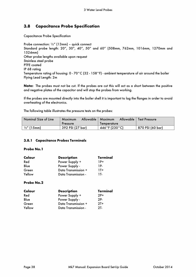
Capacitance Probe Specification Probe connection: ½” (13mm) – quick connect Standard probe length: 20”, 30”, 40”, 50” and 60” (508mm, 762mm, 1016mm, 1270mm and 1524mm) Other probe lengths available upon request Stainless steel probe PTFE coated IP 68 rating Temperature rating of housing: 0 - 70°C (32 - 158°F) - ambient temperature of air around the boiler Flying Lead Length: 2m Note: The probes must not be cut. If the probes are cut this will act as a short between the positive and negative plates of the capacitor and will stop the probes from working. If the probes are mounted directly into the boiler shell it is important to lag the flanges in order to avoid overheating of the electronics. The following table illustrates the pressure tests on the probes: Nominal Size of Line Maximum Allowable
Pressure Maximum Allowable Temperature
Test Pressure
½” (15mm) 392 PSI (27 bar) 446°F (230°C) 870 PSI (60 bar)
3.8.1 Capacitance Probes Terminals
Probe No.1 Colour Description TerminalRed Power Supply + 1P+ Blue Power Supply - 1P- Green Data Transmission + 1T+ Yellow Data Transmission - 1T- Probe No.2 Colour Description TerminalRed Power Supply + 2P+ Blue Power Supply - 2P- Green Data Transmission + 2T+ Yellow Data Transmission - 2T-
3 Water Level Probes
Page 38 Mk7 Manual: Expansion Board Set-Up Guide October 2014
3.8.2 Water Level Treatment
The water treatment regime in any boiler installation has an effect on the life of the boiler and poor water quality can also affect the performance of capacitance probes. It is important to install any level controls in accordance with the local and national authorities’ boiler inspection bodies, approval authorities and boiler manufacturer’s guidelines. As well as this, it is vitally important to select a suitable water level treatment regime to ensure correct and safe operation of the Autoflame system. The water level treatment will also affect the long term operational life of the Autoflame capacitance probes. Water treatment companies should be able to assist with the selection and implementation of a suitable water treatment regime. Generally, guidelines and standards for correct water treatment will be provided by your boiler manufacturer. The Autoflame water level capacitance probes are designed to work with steam boilers where the chemical treatment is maintained to the limits stated within these standards and guidelines. When the chemical treatment is maintained to levels under the maximum limits as stated in the standard’s tables, the water level probes will work as expected. It is important to remember that the guidelines set are limits that should not be exceeded at any time. If these guidelines and limits are not maintained then this can cause adverse effects on equipment installed as well reducing the longevity of your boiler and increasing ongoing maintenance requirements.
3 Water Level Probes
October 2014 Mk7 Manual: Expansion Board Set-Up Guide Page 39
3.9 2nd Low Probe
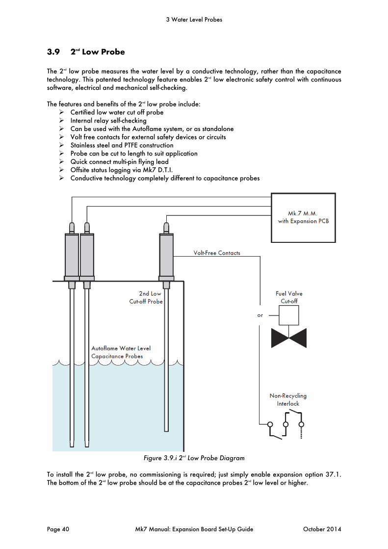
The 2nd low probe measures the water level by a conductive technology, rather than the capacitance technology. This patented technology feature enables 2nd low electronic safety control with continuous software, electrical and mechanical self-checking. The features and benefits of the 2nd low probe include: Certified low water cut off probe Internal relay self-checking Can be used with the Autoflame system, or as standalone Volt free contacts for external safety devices or circuits Stainless steel and PTFE construction Probe can be cut to length to suit application Quick connect multi-pin flying lead Offsite status logging via Mk7 D.T.I. Conductive technology completely different to capacitance probes
Figure 3.9.i 2nd Low Probe Diagram
To install the 2nd low probe, no commissioning is required; just simply enable expansion option 37.1. The bottom of the 2nd low probe should be at the capacitance probes 2nd low level or higher.
3 Water Level Probes
Page 40 Mk7 Manual: Expansion Board Set-Up Guide October 2014
3.10 Modulating Feed Water Valve
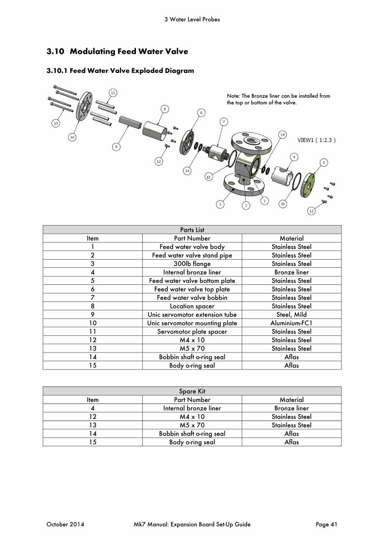
3.10.1 Feed Water Valve Exploded Diagram
Parts List Item Part Number Material
1 Feed water valve body Stainless Steel 2 Feed water valve stand pipe Stainless Steel 3 300lb flange Stainless Steel 4 Internal bronze liner Bronze liner 5 Feed water valve bottom plate Stainless Steel 6 Feed water valve top plate Stainless Steel 7 Feed water valve bobbin Stainless Steel 8 Location spacer Stainless Steel 9 Unic servomotor extension tube Steel, Mild
10 Unic servomotor mounting plate Aluminium-FC1 11 Servomotor plate spacer Stainless Steel 12 M4 x 10 Stainless Steel 13 M5 x 70 Stainless Steel 14 Bobbin shaft o-ring seal Aflas 15 Body o-ring seal Aflas
Spare Kit Item Part Number Material
4 Internal bronze liner Bronze liner 12 M4 x 10 Stainless Steel 13 M5 x 70 Stainless Steel 14 Bobbin shaft o-ring seal Aflas 15 Body o-ring seal Aflas
Note: The Bronze liner can be installed from the top or bottom of the valve.
3 Water Level Probes
October 2014 Mk7 Manual: Expansion Board Set-Up Guide Page 41
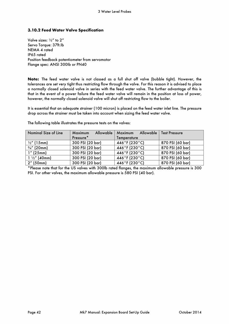
3.10.2 Feed Water Valve Specification
Valve sizes: ½” to 2” Servo Torque: 37ft.Ib NEMA 4 rated IP65 rated Position feedback potentiometer from servomotor Flange spec: ANSI 300Ib or PN40 Note: The feed water valve is not classed as a full shut off valve (bubble tight). However, the tolerances are set very tight thus restricting flow through the valve. For this reason it is advised to place a normally closed solenoid valve in series with the feed water valve. The further advantage of this is that in the event of a power failure the feed water valve will remain in the position at loss of power, however, the normally closed solenoid valve will shut off restricting flow to the boiler. It is essential that an adequate strainer (100 micron) is placed on the feed water inlet line. The pressure drop across the strainer must be taken into account when sizing the feed water valve. The following table illustrates the pressure tests on the valves: Nominal Size of Line Maximum Allowable
Pressure* Maximum Allowable Temperature
Test Pressure
½” (15mm) 300 PSI (20 bar) 446°F (230°C) 870 PSI (60 bar) ¾” (20mm) 300 PSI (20 bar) 446°F (230°C) 870 PSI (60 bar) 1” (25mm) 300 PSI (20 bar) 446°F (230°C) 870 PSI (60 bar) 1 ½” (40mm) 300 PSI (20 bar) 446°F (230°C) 870 PSI (60 bar) 2” (50mm) 300 PSI (20 bar) 446°F (230°C) 870 PSI (60 bar) *Please note that for the US valves with 300lb rated flanges, the maximum allowable pressure is 300 PSI. For other valves, the maximum allowable pressure is 580 PSI (40 bar).
3 Water Level Probes
Page 42 Mk7 Manual: Expansion Board Set-Up Guide October 2014

3.10.3 Bronze Liner
The Autoflame feed water control valves have been modified to include bronze liners. The liners have been incorporated within the design of the valve to assist with applications where the supply feed water is high in particulate, which can lead to premature valve failure. This is particularly applicable where feed water is insufficiently filtered. The liners have been designed to be easily replaced for general maintenance and service. The sizing table shows the valves available and the operating pressure requirements. It is important that the maximum stated differential pressure across the valve should not be exceeded. The differential pressure across the valve has a direct relationship to the velocity of the water through the valve. Excessive velocity will lead to premature failure of the bronze liner. There has also been the addition of high temperature bearings to hold the bobbin central in the valve; these are in the top and bottom plate. The higher velocities will not have as great an impact on the bronze liner as the PTFE liner. However if the valve only operates at the very low end, there will be long term wear of the liner edge. The valve should be sized from the tables in this section 3.10.5, not from the supply pipe size. 3.10.4 Replacing the bronze liner
When replacing the bronze liner in the valve make sure this is done in a clear area to avoid debris from entering the valve. Make sure the liner is placed on the feed water valve bobbin before inserting into the valve body. When the new liner and bobbin is re-assembled into the valve body ensure the constellations are in line with the machined pockets in the bottom plate, also ensure that the liner is in the correct orientation to the valve body as this can be installed 90 degrees out from the ports on the valve. It is not necessary to remove the entire valve from the pipe work but it is essential that the valve is sufficiently isolated and cooled before work begins.
Figure 3.10.4 Bronze Liner
3 Water Level Probes
October 2014 Mk7 Manual: Expansion Board Set-Up Guide Page 43
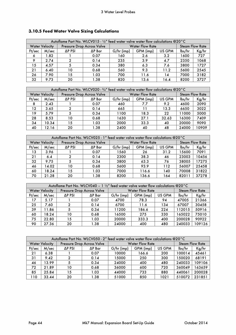
3.10.5 Feed Water Valve Sizing Calculations
Autoflame Part No. WLCV015 - ½” feed water valve water flow calculations @20°C Water Velocity Pressure Drop Across Valve Water Flow Rate Steam Flow Rate Ft/sec M/sec ∆P PSI ∆P Bar G/hr (imp) GPM (imp) US GPM lbs/hr Kg/hr
6 1.82 1 0.07 160 2.6 3.2 1600 727 9 2.74 2 0.14 235 3.9 4.7 2350 1068
15 4.57 5 0.34 380 6.3 7.6 3800 1727 21 6.40 10 0.68 560 9.3 11.2 5600 2545 26 7.90 15 1.03 700 11.6 14 7000 3182 32 9.73 20 1.38 820 13.6 16.4 8200 3727
Autoflame Part No. WLCV020 - ¾” feed water valve water flow calculations @20°C
Water Velocity Pressure Drop Across Valve Water Flow Rate Steam Flow Rate Ft/sec M/sec ∆P PSI ∆P Bar G/hr (imp) GPM (imp) US GPM lbs/hr Kg/hr
8 2.43 1 0.07 460 7.7 9.2 4600 2090 12 3.65 2 0.14 665 11 13.3 6650 3022 19 5.79 5 0.34 1100 18.3 22 11000 5000 28 8.53 10 0.68 1630 27.1 32.63 16300 7409 34 10.34 15 1.03 2000 33.3 40 20000 9090 40 12.16 20 1.38 2400 40 48 24000 10909
Autoflame Part No. WLCV025 - 1” feed water valve water flow calculations @20°C
Water Velocity Pressure Drop Across Valve Water Flow Rate Steam Flow Rate Ft/sec M/sec ∆P PSI ∆P Bar G/hr (imp) GPM (imp) US GPM lbs/hr Kg/hr
13 3.96 1 0.07 1560 26 31.2 15600 7091 21 6.4 2 0.14 2300 38.3 46 23003 1045632 9.75 5 0.34 3800 63.3 76 38005 1727546 14.02 10 0.68 5600 93.9 112 56007 2545860 18.24 15 1.03 7000 116.6 140 70008 3182270 21.28 20 1.38 8200 136.6 164 82011 37278
Autoflame Part No. WLCV040 – 1 ½” feed water valve water flow calculations @20°C
Water Velocity Pressure Drop Across Valve Water Flow Rate Steam Flow Rate Ft/sec M/sec ∆P PSI ∆P Bar G/hr (imp) GPM (imp) US GPM lbs/hr Kg/hr
17 5.17 1 0.07 4700 78.3 94 47005 21366 25 7.60 2 0.14 6700 11.6 134 67007 30458 39 11.86 5 0.34 11200 186.6 224 112015 50916 60 18.24 10 0.68 16500 275 330 165022 75010 75 22.80 15 1.03 20000 333.3 400 200028 90922 90 27.36 20 1.38 24000 400 480 240033 109126
Autoflame Part No. WLCV050 - 2” feed water valve water flow calculations @20°C Water Velocity Pressure Drop Across Valve Water Flow Rate Steam Flow Rate Ft/sec M/sec ∆P PSI ∆P Bar G/hr (imp) GPM (imp) US GPM lbs/hr Kg/hr
21 6.38 1 0.07 10000 166.6 200 100014 45461 31 9.42 2 0.14 15000 250 300 150020 68191 46 13.99 5 0.34 24000 400 480 240033 10910672 21.89 10 0.68 36000 600 720 360049 16365985 25.84 15 1.03 44000 733 880 440061 200028
110 33.44 20 1.38 51000 850 1021 510072 231851
3 Water Level Probes
Page 44 Mk7 Manual: Expansion Board Set-Up Guide October 2014
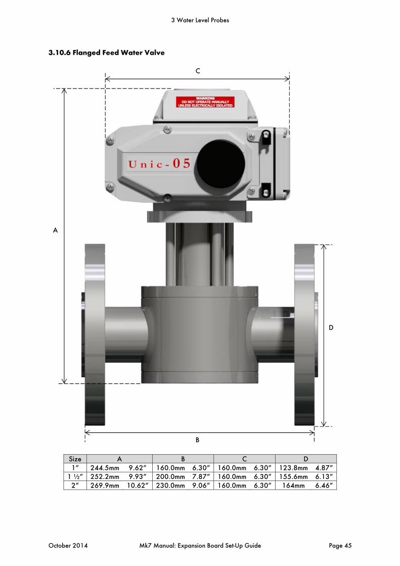
Size A B C D 1” 244.5mm 9.62” 160.0mm 6.30” 160.0mm 6.30” 123.8mm 4.87”
1 ½” 252.2mm 9.93” 200.0mm 7.87” 160.0mm 6.30” 155.6mm 6.13”2” 269.9mm 10.62” 230.0mm 9.06” 160.0mm 6.30” 164mm 6.46”
A
C
B
D
3.10.6 Flanged Feed Water Valve
3 Water Level Probes
October 2014 Mk7 Manual: Expansion Board Set-Up Guide Page 45
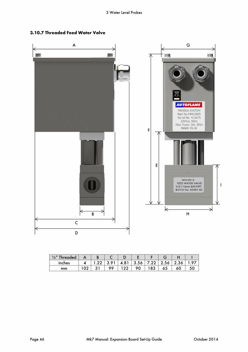
½” Threaded A B C D E F G H I inches 4 1.22 3.91 4.81 3.56 7.22 2.56 2.36 1.97
mm 102 31 99 122 90 183 65 60 50
A
D
B
C
H
F
E
G
I
3.10.7 Threaded Feed Water Valve
3 Water Level Probes
Page 46 Mk7 Manual: Expansion Board Set-Up Guide October 2014

¾” Threaded A B C D E F G H Inches 5.59 2.00 6.54 4.37 8.86 3.58 3.54 2.36
mm 142 51 166 111 225 91 90 60
A
B
C
D
E
F
G
H
3 Water Level Probes
October 2014 Mk7 Manual: Expansion Board Set-Up Guide Page 47
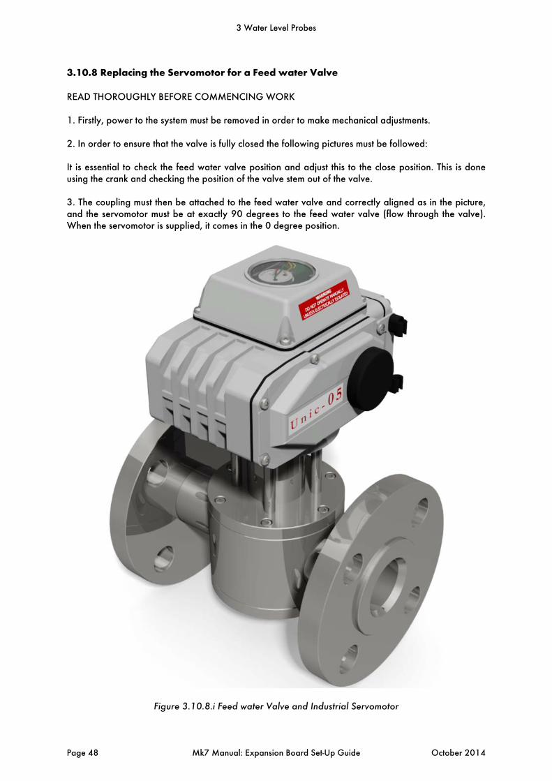
3.10.8 Replacing the Servomotor for a Feed water Valve
READ THOROUGHLY BEFORE COMMENCING WORK 1. Firstly, power to the system must be removed in order to make mechanical adjustments. 2. In order to ensure that the valve is fully closed the following pictures must be followed: It is essential to check the feed water valve position and adjust this to the close position. This is done using the crank and checking the position of the valve stem out of the valve. 3. The coupling must then be attached to the feed water valve and correctly aligned as in the picture, and the servomotor must be at exactly 90 degrees to the feed water valve (flow through the valve). When the servomotor is supplied, it comes in the 0 degree position.
Figure 3.10.8.i Feed water Valve and Industrial Servomotor
3 Water Level Probes
Page 48 Mk7 Manual: Expansion Board Set-Up Guide October 2014
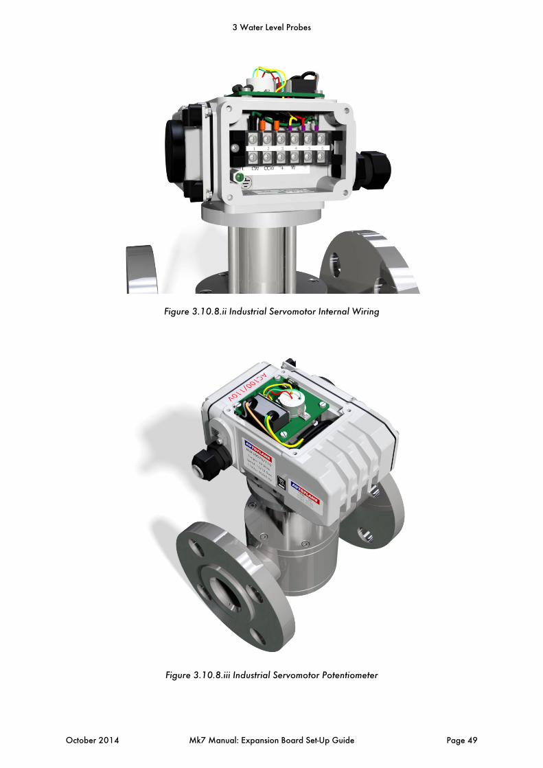
Figure 3.10.8.ii Industrial Servomotor Internal Wiring
Figure 3.10.8.iii Industrial Servomotor Potentiometer
3 Water Level Probes
October 2014 Mk7 Manual: Expansion Board Set-Up Guide Page 49

3.10.9 Storage, Operation and Maintenance
Delivery and Storage All Autoflame feed water valves are shipped in appropriate packing in the fully open position. They should be stored in a weatherproof building, and protected from ambient conditions, salt laden atmosphere and the ingress of foreign matter. If the feed water valves are not required immediately, please make sure they are stored correctly. Leave the valves stored in their original packing during the whole storage period. The valves should be kept at the open position for this duration. Inspect them periodically to ensure the valves have no damage and are clean and free form foreign materials. Any rust, dirt and foreign materials will need to be carefully removed using a cleaning cloth with solvent. After cleaning, the valves must be lubricated. Installation Prior to assembly the feed water valves should be operated for at least 2 complete cycles. Before installation, check that the pipe has no dirty parts such as calamine, residues of welding or burring, metallic filings etc. Be sure that the line is free from tractions and torsions, and that the valve is in axis with the tube, installed initially with the valve in the open position. Valves should be installed by qualified factory trained technicians. Operation The valve is controlled automatically by the M.M. water level control via the expansion board. The indicator on the base of the valve shows the position of the feed water valve. When the line points in the direction of the flow of the water, the valve is open. When the line is perpendicular to the flow of water, the valve is closed. For best results and a longer life, the Autoflame valves should be used within the pressure/ temperature limits of the valve. The materials of the body/trim of the valve should be compatible with the chemical characteristics of the medium. Maintenance and Servicing It is recommended that an annual service is made on the feed water valve. Electrically isolate the servomotor on the feed water valve and then remove the cabling, making a note of the wiring arrangement. The feed water valve must be mechanically isolated and can now be removed for servicing. It is important that the o-rings are greased within the feed water valve. Once this has been checked the feed water valve should be operated for 2 complete cycles. Warnings On site, there must be suitable and safety control devices to avoid over-pressure and over-temperature. The surrounding temperature should always be significantly lower than the inflammable temperature of the surrounding atmosphere and the accumulated dust. External factors need to be considered such as freezing, dynamic effects due to the line vibration, and extreme weather scenarios. For boiler plants in particularly humid areas, near to the sea or other hostile places, the valve material will need to be considered together with the external protective painting for external corrosion.
3 Water Level Probes
Page 50 Mk7 Manual: Expansion Board Set-Up Guide October 2014
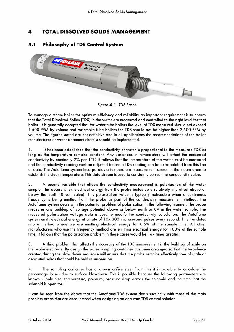
4 TOTAL DISSOLVED SOLIDS MANAGEMENT
4.1 Philosophy of TDS Control System
Figure 4.1.i TDS Probe
To manage a steam boiler for optimum efficiency and reliability an important requirement is to ensure that the Total Dissolved Solids (TDS) in the water are measured and controlled to the right level for that boiler. It is generally accepted that for water tube boilers the level of TDS measured should not exceed 1,500 PPM by volume and for smoke tube boilers the TDS should not be higher than 2,500 PPM by volume. The figures stated are not definitive and in all applications the recommendations of the boiler manufacturer or water treatment chemist should be implemented. 1. It has been established that the conductivity of water is proportional to the measured TDS as long as the temperature remains constant. Any variations in temperature will affect the measured conductivity by nominally 2% per 1°C. It follows that the temperature of the water must be measured and the conductivity reading must be adjusted before a TDS reading can be extrapolated from this line of data. The Autoflame system incorporates a temperature measurement sensor in the steam drum to establish the steam temperature. This data stream is used to constantly correct the conductivity value. 2. A second variable that effects the conductivity measurement is polarization of the water sample. This occurs when electrical energy from the probe builds up a relatively tiny offset above or below the earth (0 volt value). This polarization value is typically noticeable when a continuous frequency is being emitted from the probe as part of the conductivity measurement method. The Autoflame system deals with the potential problem of polarization in the following manner. The probe measures any build-up of voltage potential above or below earth or 0V in the water sample. The measured polarization voltage data is used to modify the conductivity calculation. The Autoflame system emits electrical energy at a rate of 10x 300 microsecond pulses every second. This translates into a method where we are emitting electrical energy for 0.6% of the sample time. All other manufacturers who use the frequency method are emitting electrical energy for 100% of the sample time. It follows that the polarization problem in these cases would be 167 times greater! 3. A third problem that affects the accuracy of the TDS measurement is the build up of scale on the probe electrode. By design the water sampling container has been arranged so that the turbulence created during the blow down sequence will ensure that the probe remains effectively free of scale or deposited solids that could be held in suspension. 4. The sampling container has a known orifice size. From this it is possible to calculate the percentage losses due to surface blowdown. This is possible because the following parameters are known – hole size, temperature, pressure, pressure drop across the solenoid and the time that the solenoid is open for. It can be seen from the above that the Autoflame TDS system deals succinctly with three of the main problem areas that are encountered when designing an accurate TDS control solution.
4 Total Dissolved Solids Management
October 2014 Mk7 Manual: Expansion Board Set-Up Guide Page 51

4.2 TDS Probe Calibration
Figure 4.2.i System Configuration
Once the expansions have been set for the TDS probe, the probe must be calibrated. While the M.M.
is in Run mode, press and then press in the System Configuration screen as in Figure 4.2.i.
4 Total Dissolved Solids Management
Page 52 Mk7 Manual: Expansion Board Set-Up Guide October 2014
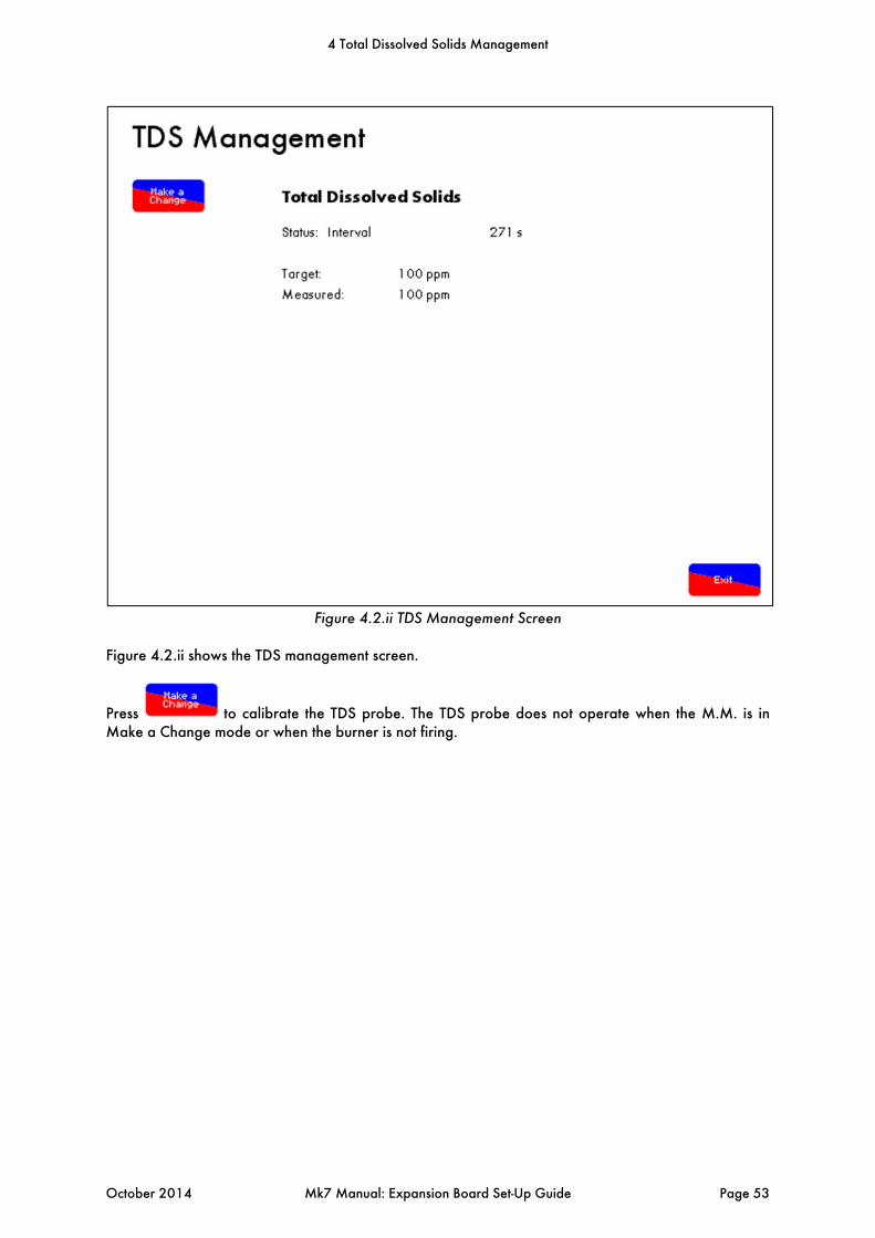
Figure 4.2.ii TDS Management Screen
Figure 4.2.ii shows the TDS management screen.
Press to calibrate the TDS probe. The TDS probe does not operate when the M.M. is in Make a Change mode or when the burner is not firing.
4 Total Dissolved Solids Management
October 2014 Mk7 Manual: Expansion Board Set-Up Guide Page 53
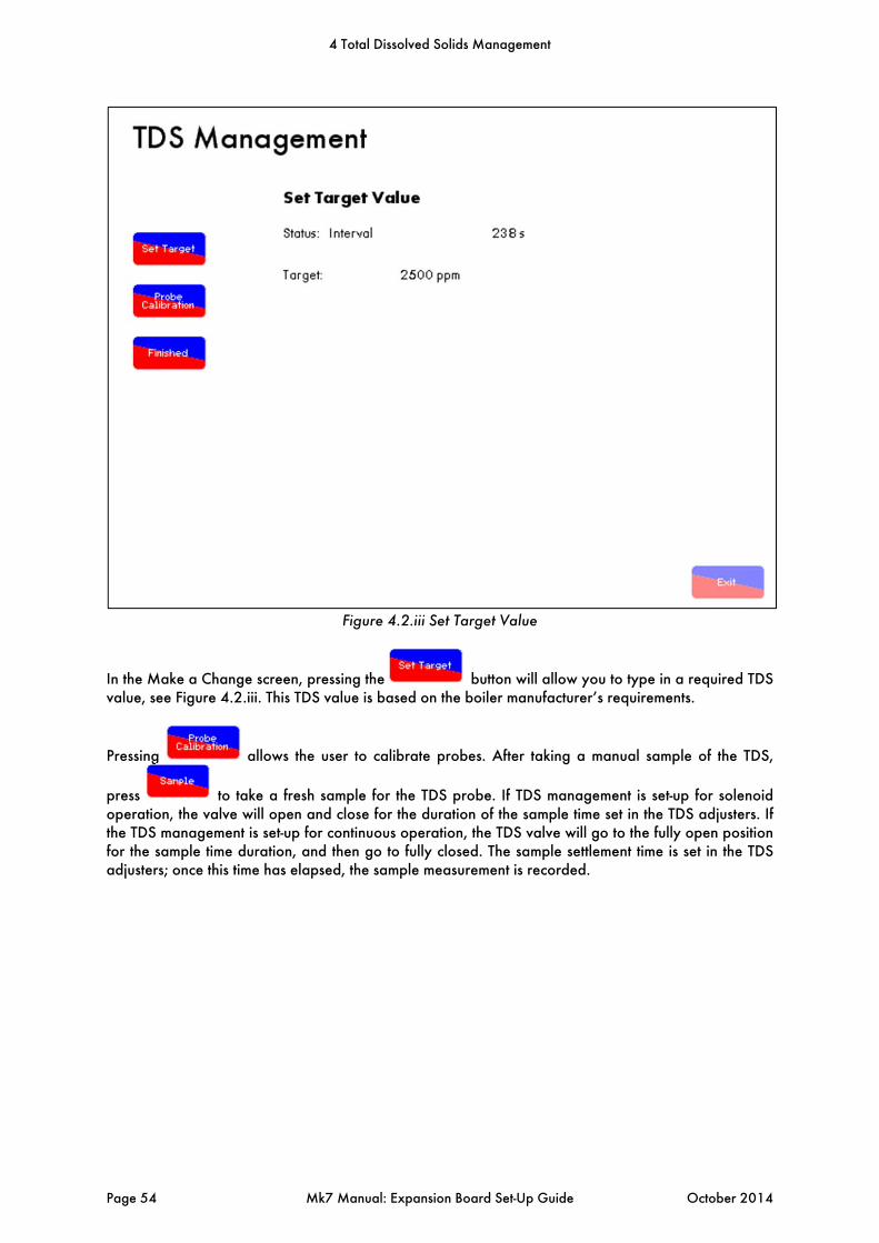
Figure 4.2.iii Set Target Value
In the Make a Change screen, pressing the button will allow you to type in a required TDS value, see Figure 4.2.iii. This TDS value is based on the boiler manufacturer’s requirements.
Pressing allows the user to calibrate probes. After taking a manual sample of the TDS,
press to take a fresh sample for the TDS probe. If TDS management is set-up for solenoid operation, the valve will open and close for the duration of the sample time set in the TDS adjusters. If the TDS management is set-up for continuous operation, the TDS valve will go to the fully open position for the sample time duration, and then go to fully closed. The sample settlement time is set in the TDS adjusters; once this time has elapsed, the sample measurement is recorded.
4 Total Dissolved Solids Management
Page 54 Mk7 Manual: Expansion Board Set-Up Guide October 2014
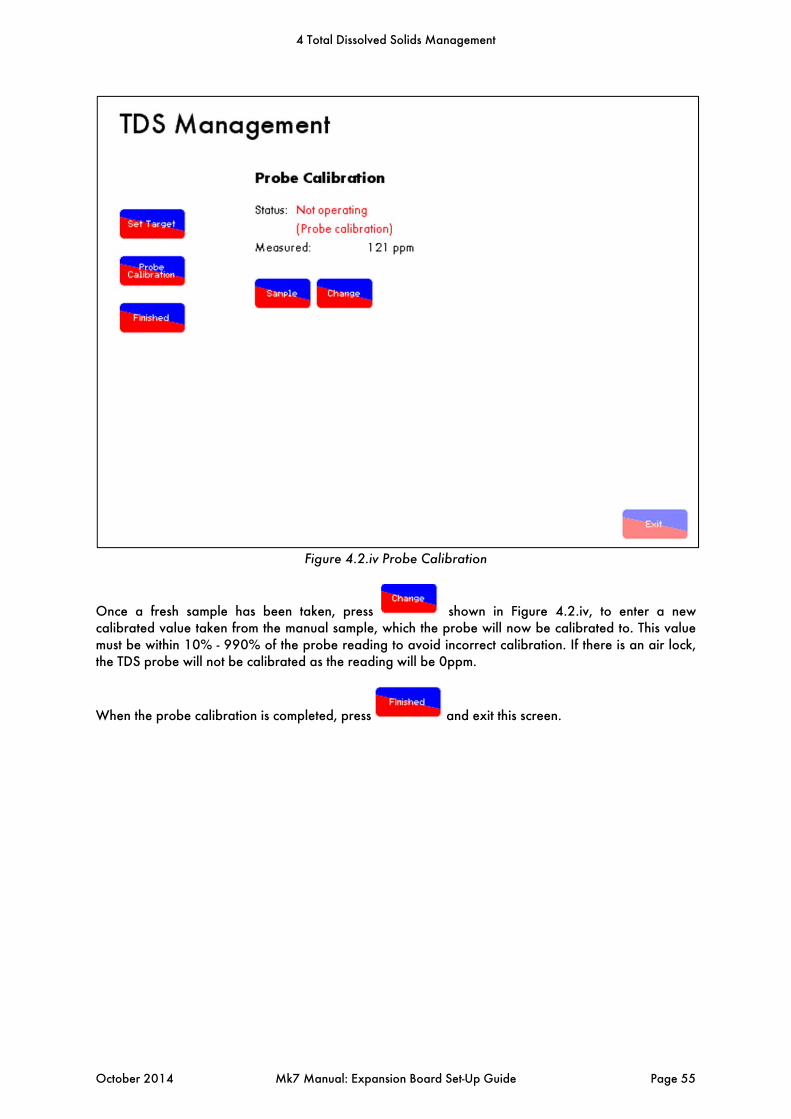
Figure 4.2.iv Probe Calibration
Once a fresh sample has been taken, press shown in Figure 4.2.iv, to enter a new calibrated value taken from the manual sample, which the probe will now be calibrated to. This value must be within 10% - 990% of the probe reading to avoid incorrect calibration. If there is an air lock, the TDS probe will not be calibrated as the reading will be 0ppm.
When the probe calibration is completed, press and exit this screen.
4 Total Dissolved Solids Management
October 2014 Mk7 Manual: Expansion Board Set-Up Guide Page 55
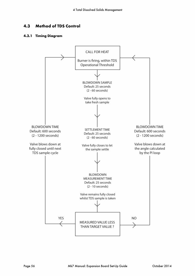
CALL FOR HEAT
Burner is firing, within TDS Operational Threshold
BLOWDOWN SAMPLEDefault: 25 seconds
(2 - 60 seconds)
Valve fully opens to take fresh sample
SETTLEMENT TIMEDefault: 25 seconds
(2 - 60 seconds)
Valve fully closes to let the sample settle
BLOWDOWN MEASUREMENT TIMEDefault: 25 seconds
(2 - 10 seconds)
Valve remains fully closed whilst TDS sample is taken
MEASURED VALUE LESS THAN TARGET VALUE ?
YES NO
BLOWDOWN TIMEDefault: 600 seconds
(2 - 1200 seconds)
Valve blows down at the angle calculated
by the PI loop
BLOWDOWN TIMEDefault: 600 seconds
(2 - 1200 seconds)
Valve blows down at fully closed until next
TDS sample cycle
4.3 Method of TDS Control
4.3.1 Timing Diagram
4 Total Dissolved Solids Management
Page 56 Mk7 Manual: Expansion Board Set-Up Guide October 2014

4.3.2 Continuous TDS Blowdown
The new TDS blowdown operation will hold the valve at a calculated value for the duration of the top blowdown. The top blowdown will not operate if the burner is not firing or if the water is within the allowed TDS threshold. The following procedure takes place during the continuous TDS operation:
1. From a closed position, the TDS valve fully opens to gain a fresh sample.
2. The valve then fully closes, allowing a settle time; the sample is then measured.
3. If the TDS value is above the target TDS value, the valve will use a PI loop to calculate a fixed angle for the blowdown; it will hold this position for the duration of the blowdown timing.
4. Once the top blowdown time has elapsed, the sequence shall start again.
5. Once the TDS value has been reached or decreased to below the target TDS value, the valve shall remain closed for the duration of the blowdown timing.
6. This PI loop control will continue to maintain the target TDS value. 4.3.3 Solenoid Valve TDS Blowdown
The sampling and control sequence of the top blowdown using the solenoid valve is detailed below:
1. If the boiler water sample is above the required TDS value the system will open the top blowdown control valve for 5-300 seconds. This time duration is user variable and is designated blowdown time.
2. After blow down the system invokes a 5 second settlement interval.
3. After the settlement period a 5 second measurement routine is carried out to establish the
current TDS level.
4. If the boiler water sample is still above the required TDS value the system will repeat the top ‘Blowdown Time’ routine as detailed above in 1) BDT.
5. When the boiler water sample is measured as below the required TDS level, the system will
then take a sample every 60-300 seconds. This sample time interval is user variable.
6. The duration of the sample time is 3-10 seconds. This is user variable.
7. The system then repeats this cycle.
4 Total Dissolved Solids Management
October 2014 Mk7 Manual: Expansion Board Set-Up Guide Page 57

4.3.4 Installation of TDS Probe Assembly
Illustrated below is the installation method for the T.D.S. probe incorporating Autoflame’s sampling system. (All dotted components are to be supplied by the customer). Note: There must be a minimum of 3ft (0.9m) straight pipe installed from the valve, of the same diameter as the actual valve.
Figure 4.3.2.i Vertically Mounted
4 Total Dissolved Solids Management
Page 58 Mk7 Manual: Expansion Board Set-Up Guide October 2014
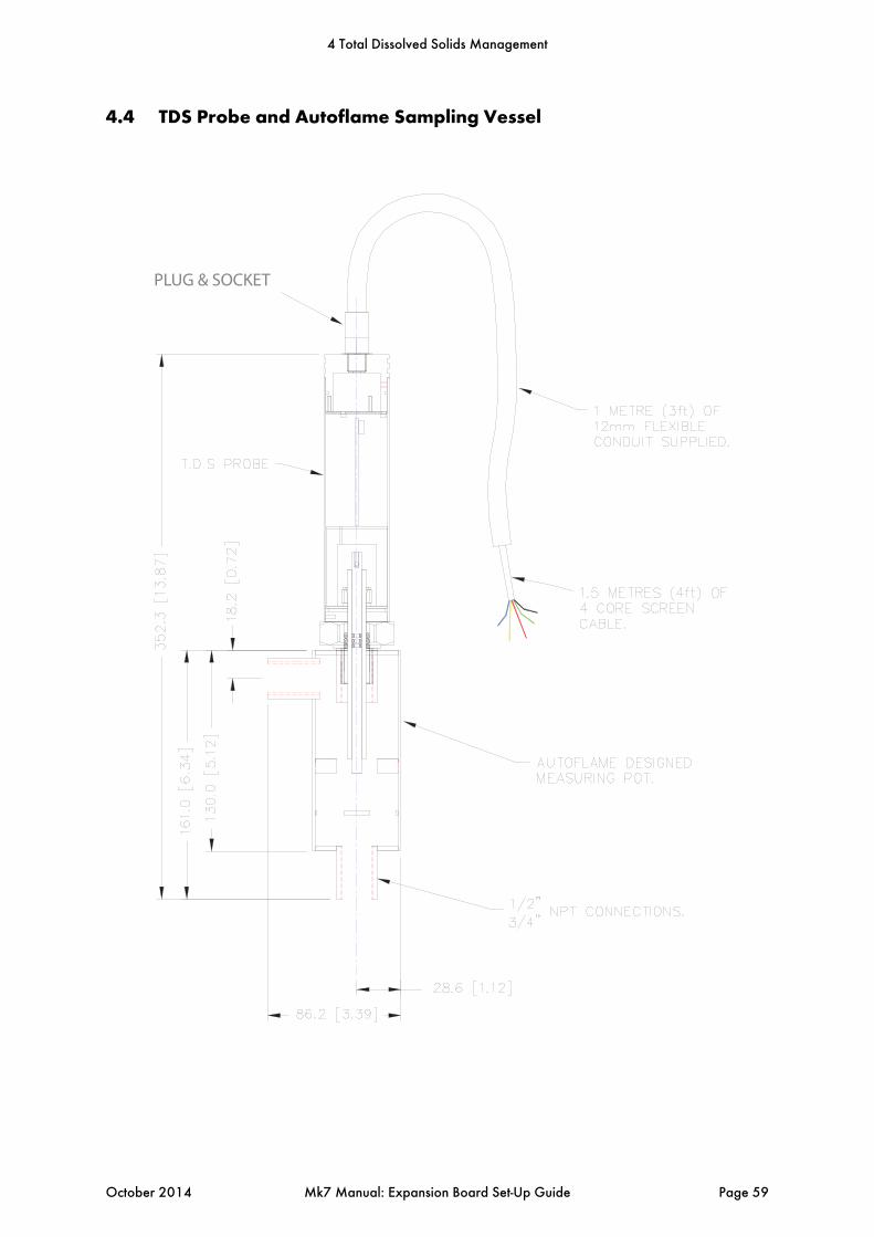
4.4 TDS Probe and Autoflame Sampling Vessel
PLUG & SOCKET
4 Total Dissolved Solids Management
October 2014 Mk7 Manual: Expansion Board Set-Up Guide Page 59
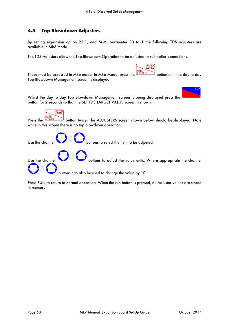
4.5 Top Blowdown Adjusters
By setting expansion option 23.1, and M.M. parameter 83 to 1 the following TDS adjusters are available in Mk6 mode. The TDS Adjusters allow the Top Blowdown Operation to be adjusted to suit boiler’s conditions.
These must be accessed in Mk6 mode. In Mk6 Mode, press the button until the day to day Top Blowdown Management screen is displayed.
Whilst the day to day Top Blowdown Management screen is being displayed press the button for 2 seconds so that the SET TDS TARGET VALUE screen is shown.
Press the button twice. The ADJUSTERS screen shown below should be displayed. Note while in this screen there is no top blowdown operation.
Use the channel buttons to select the item to be adjusted.
Use the channel buttons to adjust the value units. Where appropriate the channel
buttons can also be used to change the value by 10. Press RUN to return to normal operation. When the run button is pressed, all Adjuster values are stored in memory.
4 Total Dissolved Solids Management
Page 60 Mk7 Manual: Expansion Board Set-Up Guide October 2014
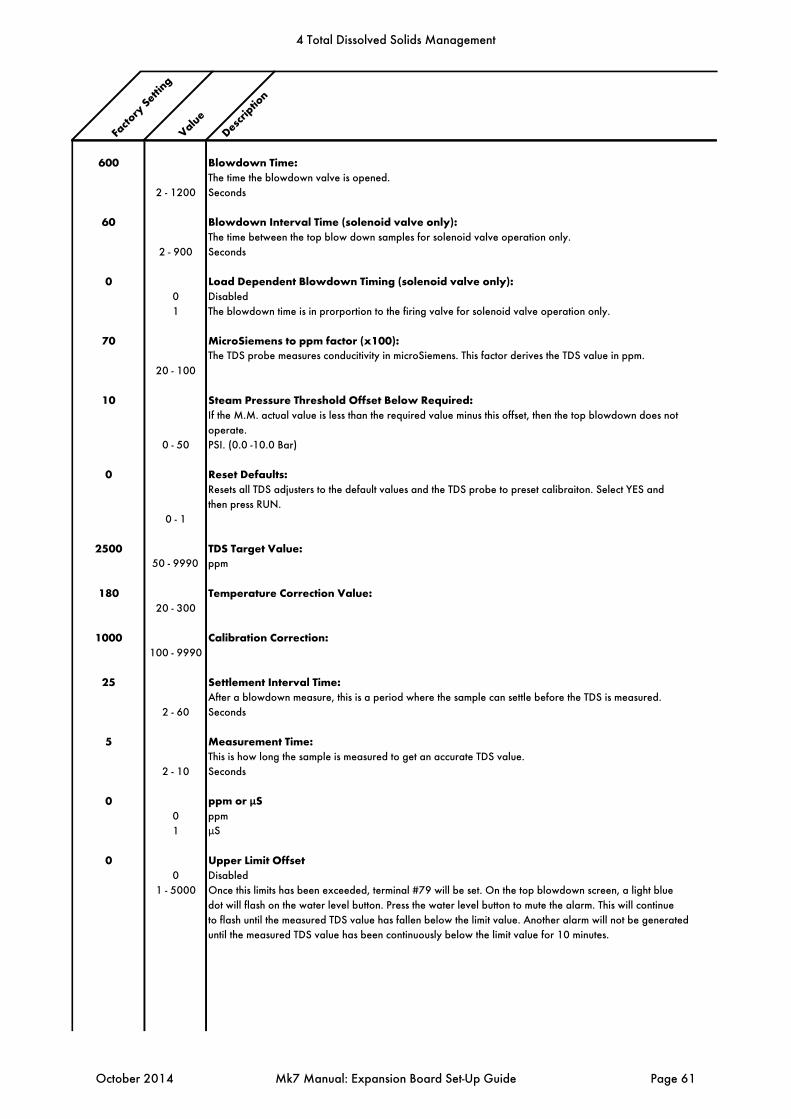
Facto
ry Setti
ng
ValueDescr
iption
600 Blowdown Time: The time the blowdown valve is opened.
2 - 1200 Seconds
60 Blowdown Interval Time (solenoid valve only):The time between the top blow down samples for solenoid valve operation only.
2 - 900 Seconds
0 Load Dependent Blowdown Timing (solenoid valve only):0 Disabled
1 The blowdown time is in prorportion to the firing valve for solenoid valve operation only.
70 MicroSiemens to ppm factor (x100):The TDS probe measures conducitivity in microSiemens. This factor derives the TDS value in ppm.
20 - 100
10 Steam Pressure Threshold Offset Below Required:If the M.M. actual value is less than the required value minus this offset, then the top blowdown does not
operate.
0 - 50 PSI. (0.0 -10.0 Bar)
0 Reset Defaults: Resets all TDS adjusters to the default values and the TDS probe to preset calibraiton. Select YES and
then press RUN.
0 - 1
2500 TDS Target Value:50 - 9990 ppm
180 Temperature Correction Value:20 - 300
1000 Calibration Correction:100 - 9990
25 Settlement Interval Time:After a blowdown measure, this is a period where the sample can settle before the TDS is measured.
2 - 60 Seconds
5 Measurement Time:This is how long the sample is measured to get an accurate TDS value.
2 - 10 Seconds
0 ppm or µS0 ppm
1 µS
0 Upper Limit Offset0 Disabled
1 - 5000 Once this limits has been exceeded, terminal #79 will be set. On the top blowdown screen, a light blue
dot will flash on the water level button. Press the water level button to mute the alarm. This will continue
to flash until the measured TDS value has fallen below the limit value. Another alarm will not be generated
until the measured TDS value has been continuously below the limit value for 10 minutes.
4 Total Dissolved Solids Management
October 2014 Mk7 Manual: Expansion Board Set-Up Guide Page 61
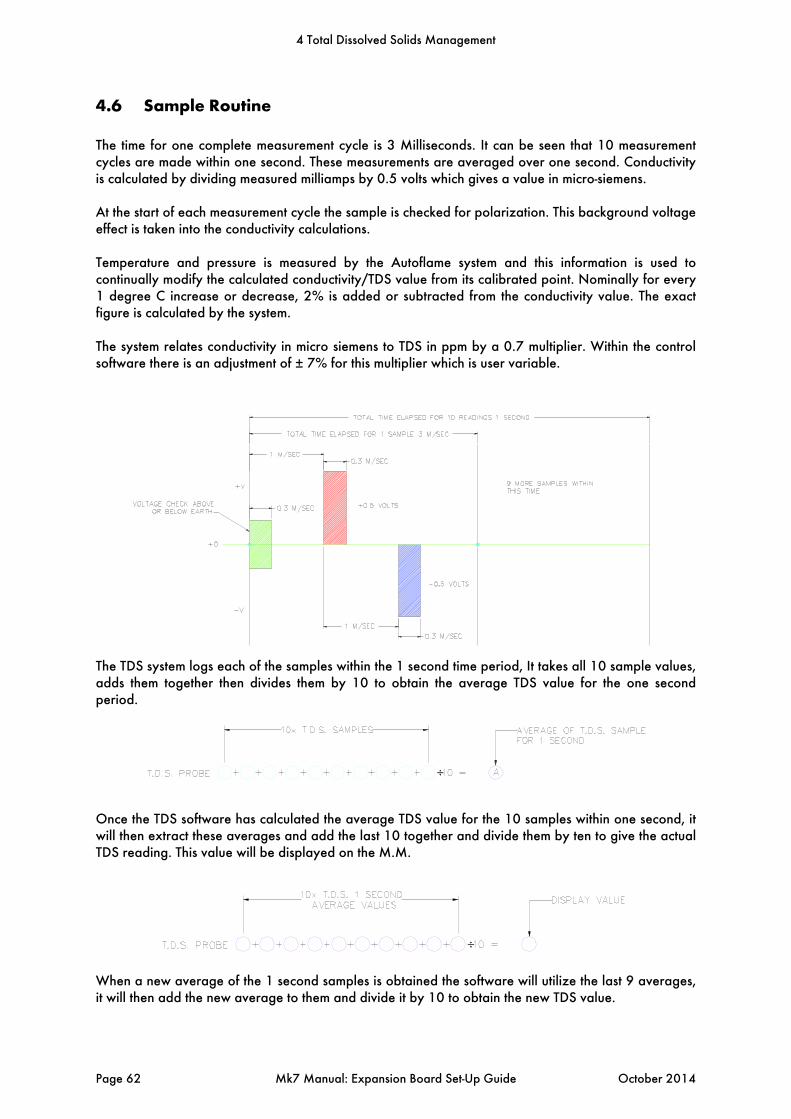
4.6 Sample Routine
The time for one complete measurement cycle is 3 Milliseconds. It can be seen that 10 measurement cycles are made within one second. These measurements are averaged over one second. Conductivity is calculated by dividing measured milliamps by 0.5 volts which gives a value in micro-siemens. At the start of each measurement cycle the sample is checked for polarization. This background voltage effect is taken into the conductivity calculations. Temperature and pressure is measured by the Autoflame system and this information is used to continually modify the calculated conductivity/TDS value from its calibrated point. Nominally for every 1 degree C increase or decrease, 2% is added or subtracted from the conductivity value. The exact figure is calculated by the system. The system relates conductivity in micro siemens to TDS in ppm by a 0.7 multiplier. Within the control software there is an adjustment of ± 7% for this multiplier which is user variable.
The TDS system logs each of the samples within the 1 second time period, It takes all 10 sample values, adds them together then divides them by 10 to obtain the average TDS value for the one second period.
Once the TDS software has calculated the average TDS value for the 10 samples within one second, it will then extract these averages and add the last 10 together and divide them by ten to give the actual TDS reading. This value will be displayed on the M.M.
When a new average of the 1 second samples is obtained the software will utilize the last 9 averages, it will then add the new average to them and divide it by 10 to obtain the new TDS value.
4 Total Dissolved Solids Management
Page 62 Mk7 Manual: Expansion Board Set-Up Guide October 2014

4.7 Relationship between Conductivity, Temp and TDS Values
A = These values measured by probe & sensors at operating steady state conditions. B = This value is conductivity value multiplied by 0.7 (TDS in PPM) C = This conductivity value temperature corrected to 25 degrees C / 77 degrees F. D = This is measured TDS value entered into the system to effect a user “calibration.”
1. Conductivity measurement corrected at 2% per 1°C. 2. At 25°C TDS in ppm is calculated by multiplying the conductivity value by 0.7. 3. Both of the above multipliers are user variable to accommodate specific site conditions. At the time of manufacture every TDS probe has buried in its electronics memory a “Calibration Correction Coefficient” or CCC This is effected as set out below. The TDS probe in a sampling vessel is immersed in a boiler water sample of a known TDS (i.e. 3500ppm for example). This is carried out at 25°C (77°F) which would give a reading in micro-siemens of 5000. If the reading from the probe electronics does not agree with this a correction multiplier or divider is implanted into this specific probes electronic memory. This is its own dedicated CCC value.
4 Total Dissolved Solids Management
October 2014 Mk7 Manual: Expansion Board Set-Up Guide Page 63

5 BOTTOM BLOWDOWN
5.1 Overview of Bottom Blowdown
5.1.1 Features and Benefits
Bottom blowdown is used to remove solids which build up at the bottom of steam boilers. In the Autoflame system, there are options to either manage the blowdowns through automatic timings, or to manually trigger them. The programmable electronic automatic blowdown ensures repeatable blowdown timings, without the need of a compressed air supply. A pulsed bottom blowdown is used to disturb settled solids at the bottom of the boiler, making the evacuation effect more efficient. The timings and intervals of the bottom blowdowns are user configurable. The benefits of the Autoflame bottom blowdown system include:
Full stainless steel valve construction with replaceable bronze liner 24V DC Autoflame Unic 5 servomotor for control and repeatability Electronic proof of open/close end switches Lithium ion battery technology ensures guaranteed closure on power failure Total electronic operation – no compressed air supply Timed blowdown with manual/automatic operation Bottom blowdown sequence logging Up to 4 timed blowdowns over a 24 hour period Repeatable up to 10 times from 1 to 60 seconds for each blowdown ‘Parked’ position to reduce valve opening time Quick servomotor disconnect facility for manual actuation Rotary operation ensures water tight shutoff Sealing design concept ensures no leaks
Valve Specifications Power Supply: 24V DC Flange Connection: 400lb/ PN40 Valve Sizes: 1”, 1 ½”, and 2”
Figure 5.1.1.i Bottom Blowdown Valve and Industrial Unic 5 Servomotor
5 Bottom Blowdown
Page 64 Mk7 Manual: Expansion Board Set-Up Guide October 2014
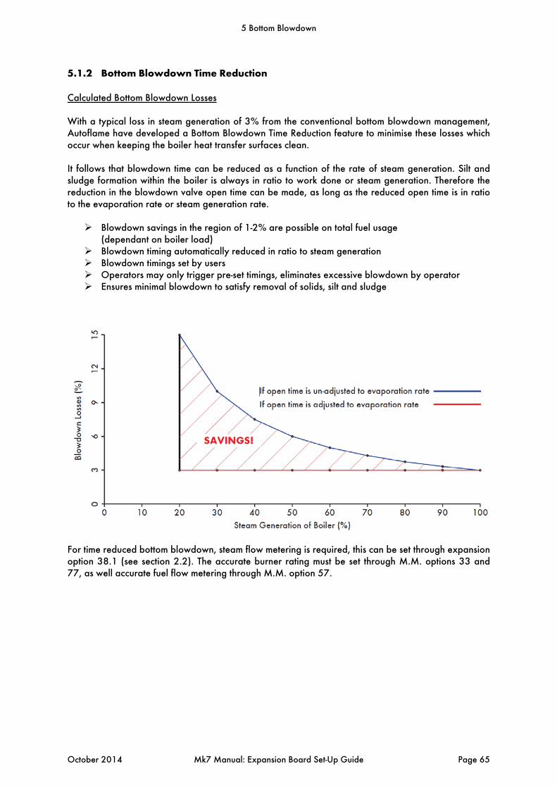
5.1.2 Bottom Blowdown Time Reduction
Calculated Bottom Blowdown Losses With a typical loss in steam generation of 3% from the conventional bottom blowdown management, Autoflame have developed a Bottom Blowdown Time Reduction feature to minimise these losses which occur when keeping the boiler heat transfer surfaces clean. It follows that blowdown time can be reduced as a function of the rate of steam generation. Silt and sludge formation within the boiler is always in ratio to work done or steam generation. Therefore the reduction in the blowdown valve open time can be made, as long as the reduced open time is in ratio to the evaporation rate or steam generation rate. Blowdown savings in the region of 1-2% are possible on total fuel usage
(dependant on boiler load) Blowdown timing automatically reduced in ratio to steam generation Blowdown timings set by users Operators may only trigger pre-set timings, eliminates excessive blowdown by operator Ensures minimal blowdown to satisfy removal of solids, silt and sludge
For time reduced bottom blowdown, steam flow metering is required, this can be set through expansion option 38.1 (see section 2.2). The accurate burner rating must be set through M.M. options 33 and 77, as well accurate fuel flow metering through M.M. option 57.
5 Bottom Blowdown
October 2014 Mk7 Manual: Expansion Board Set-Up Guide Page 65
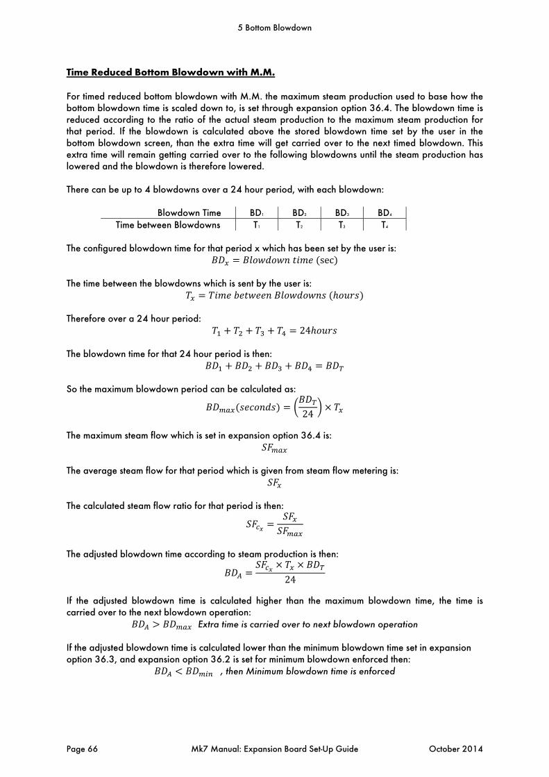
Time Reduced Bottom Blowdown with M.M. For timed reduced bottom blowdown with M.M. the maximum steam production used to base how the bottom blowdown time is scaled down to, is set through expansion option 36.4. The blowdown time is reduced according to the ratio of the actual steam production to the maximum steam production for that period. If the blowdown is calculated above the stored blowdown time set by the user in the bottom blowdown screen, than the extra time will get carried over to the next timed blowdown. This extra time will remain getting carried over to the following blowdowns until the steam production has lowered and the blowdown is therefore lowered. There can be up to 4 blowdowns over a 24 hour period, with each blowdown:
Blowdown Time BD1 BD2 BD3 BD4 Time between Blowdowns T1 T2 T3 T4
The configured blowdown time for that period x which has been set by the user is:
sec The time between the blowdowns which is sent by the user is:
Therefore over a 24 hour period:
24 The blowdown time for that 24 hour period is then:
So the maximum blowdown period can be calculated as:
24
The maximum steam flow which is set in expansion option 36.4 is:
The average steam flow for that period which is given from steam flow metering is:
The calculated steam flow ratio for that period is then:
The adjusted blowdown time according to steam production is then:
24
If the adjusted blowdown time is calculated higher than the maximum blowdown time, the time is carried over to the next blowdown operation:
Extra time is carried over to next blowdown operation
If the adjusted blowdown time is calculated lower than the minimum blowdown time set in expansion option 36.3, and expansion option 36.2 is set for minimum blowdown enforced then:
, then Minimum blowdown time is enforced
5 Bottom Blowdown
Page 66 Mk7 Manual: Expansion Board Set-Up Guide October 2014
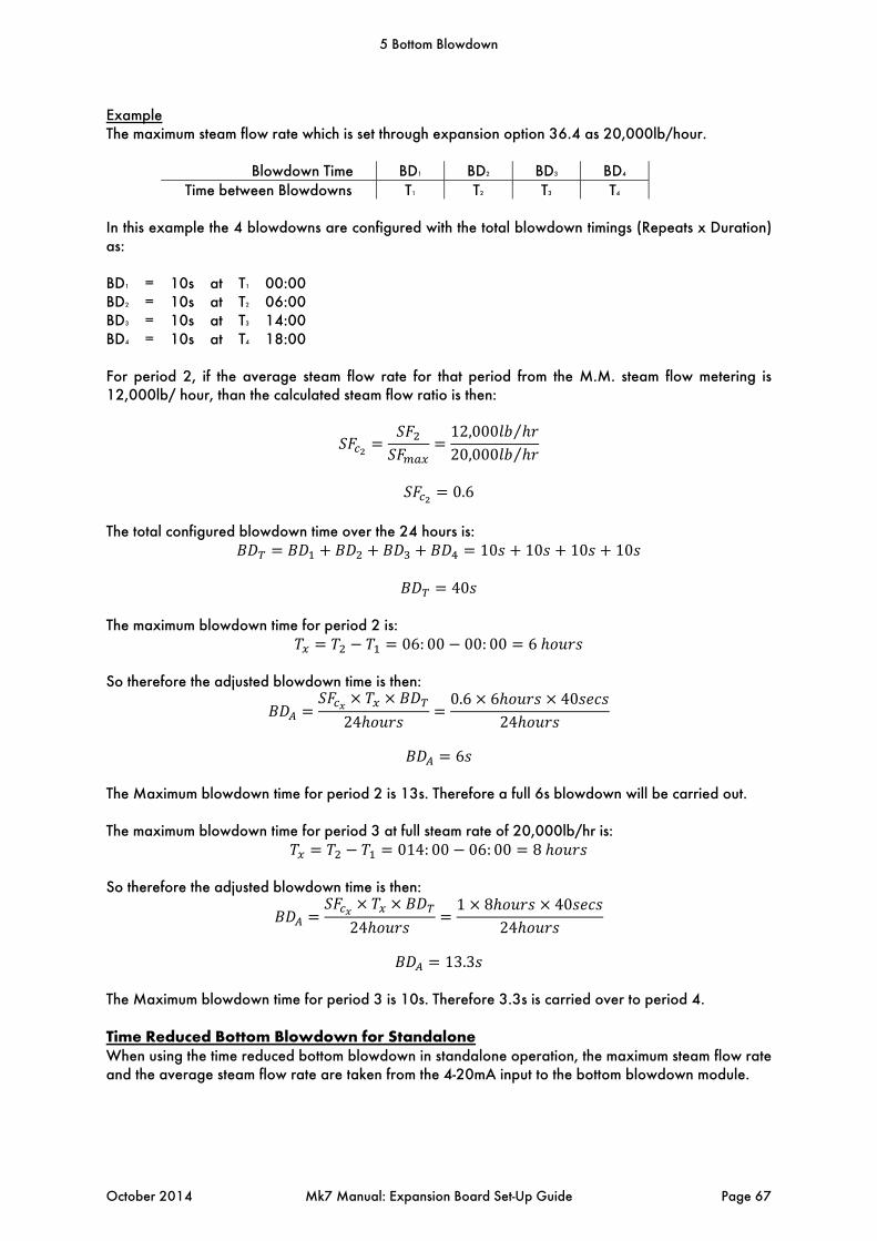
Example The maximum steam flow rate which is set through expansion option 36.4 as 20,000lb/hour.
Blowdown Time BD1 BD2 BD3 BD4 Time between Blowdowns T1 T2 T3 T4
In this example the 4 blowdowns are configured with the total blowdown timings (Repeats x Duration) as: BD1 = 10s at T1 00:00 BD2 = 10s at T2 06:00 BD3 = 10s at T3 14:00 BD4 = 10s at T4 18:00 For period 2, if the average steam flow rate for that period from the M.M. steam flow metering is 12,000lb/ hour, than the calculated steam flow ratio is then:
12,000 ⁄
20,000 ⁄
0.6
The total configured blowdown time over the 24 hours is:
10 10 10 10
40 The maximum blowdown time for period 2 is:
06: 00 00: 00 6 So therefore the adjusted blowdown time is then:
240.6 6 40
24
6
The Maximum blowdown time for period 2 is 13s. Therefore a full 6s blowdown will be carried out. The maximum blowdown time for period 3 at full steam rate of 20,000lb/hr is:
014: 00 06: 00 8 So therefore the adjusted blowdown time is then:
241 8 40
24
13.3
The Maximum blowdown time for period 3 is 10s. Therefore 3.3s is carried over to period 4. Time Reduced Bottom Blowdown for Standalone When using the time reduced bottom blowdown in standalone operation, the maximum steam flow rate and the average steam flow rate are taken from the 4-20mA input to the bottom blowdown module.
5 Bottom Blowdown
October 2014 Mk7 Manual: Expansion Board Set-Up Guide Page 67

5.1.3 Bottom Blowdown Valve Drawings
5 Bottom Blowdown
Page 68 Mk7 Manual: Expansion Board Set-Up Guide October 2014
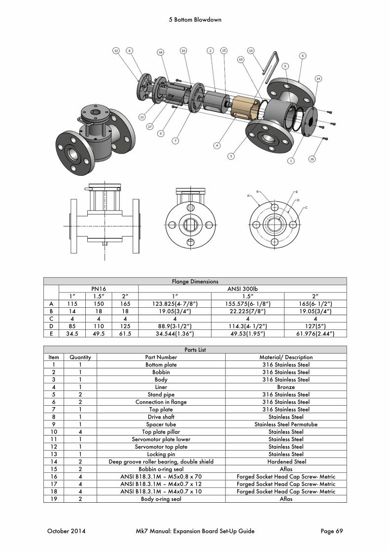
Flange Dimensions PN16 ANSI 300lb
1” 1.5” 2” 1” 1.5” 2” A 115 150 165 123.825(4- 7/8”) 155.575(6- 1/8”) 165(6- 1/2”) B 14 18 18 19.05(3/4”) 22.225(7/8”) 19.05(3/4”) C 4 4 4 4 4 4 D 85 110 125 88.9(3-1/2”) 114.3(4- 1/2”) 127(5”) E 34.5 49.5 61.5 34.544(1.36”) 49.53(1.95”) 61.976(2.44”)
Parts List
Item Quantity Part Number Material/ Description 1 1 Bottom plate 316 Stainless Steel 2 1 Bobbin 316 Stainless Steel 3 1 Body 316 Stainless Steel 4 1 Liner Bronze 5 2 Stand pipe 316 Stainless Steel 6 2 Connection in flange 316 Stainless Steel 7 1 Top plate 316 Stainless Steel 8 1 Drive shaft Stainless Steel 9 1 Spacer tube Stainless Steel Permatube
10 4 Top plate pillar Stainless Steel 11 1 Servomotor plate lower Stainless Steel 12 1 Servomotor top plate Stainless Steel 13 1 Locking pin Stainless Steel 14 2 Deep groove roller bearing, double shield Hardened Steel 15 2 Bobbin o-ring seal Aflas 16 4 ANSI B18.3.1M – M5x0.8 x 70 Forged Socket Head Cap Screw- Metric 17 4 ANSI B18.3.1M – M4x0.7 x 12 Forged Socket Head Cap Screw- Metric 18 4 ANSI B18.3.1M – M4x0.7 x 10 Forged Socket Head Cap Screw- Metric 19 2 Body o-ring seal Aflas
5 Bottom Blowdown
October 2014 Mk7 Manual: Expansion Board Set-Up Guide Page 69
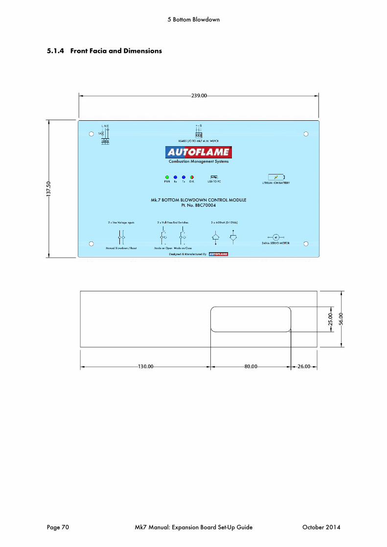
5.1.4 Front Facia and Dimensions
5 Bottom Blowdown
Page 70 Mk7 Manual: Expansion Board Set-Up Guide October 2014
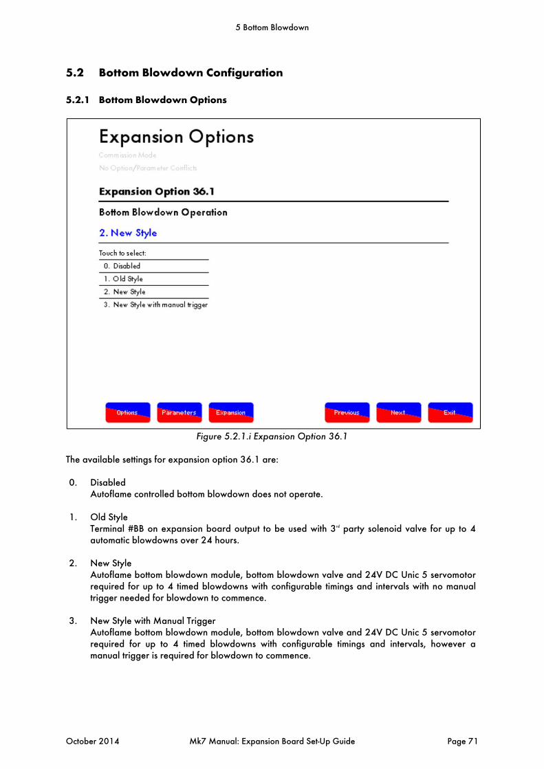
5.2 Bottom Blowdown Configuration
5.2.1 Bottom Blowdown Options
Figure 5.2.1.i Expansion Option 36.1
The available settings for expansion option 36.1 are: 0. Disabled Autoflame controlled bottom blowdown does not operate.
1. Old Style Terminal #BB on expansion board output to be used with 3rd party solenoid valve for up to 4
automatic blowdowns over 24 hours.
2. New Style Autoflame bottom blowdown module, bottom blowdown valve and 24V DC Unic 5 servomotor
required for up to 4 timed blowdowns with configurable timings and intervals with no manual trigger needed for blowdown to commence.
3. New Style with Manual Trigger Autoflame bottom blowdown module, bottom blowdown valve and 24V DC Unic 5 servomotor
required for up to 4 timed blowdowns with configurable timings and intervals, however a manual trigger is required for blowdown to commence.
5 Bottom Blowdown
October 2014 Mk7 Manual: Expansion Board Set-Up Guide Page 71
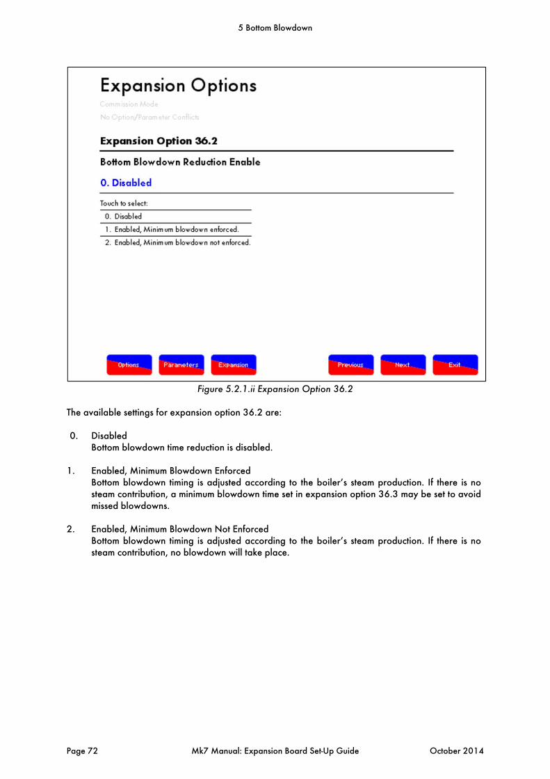
Figure 5.2.1.ii Expansion Option 36.2
The available settings for expansion option 36.2 are: 0. Disabled Bottom blowdown time reduction is disabled.
1. Enabled, Minimum Blowdown Enforced Bottom blowdown timing is adjusted according to the boiler’s steam production. If there is no
steam contribution, a minimum blowdown time set in expansion option 36.3 may be set to avoid missed blowdowns.
2. Enabled, Minimum Blowdown Not Enforced Bottom blowdown timing is adjusted according to the boiler’s steam production. If there is no
steam contribution, no blowdown will take place.
5 Bottom Blowdown
Page 72 Mk7 Manual: Expansion Board Set-Up Guide October 2014
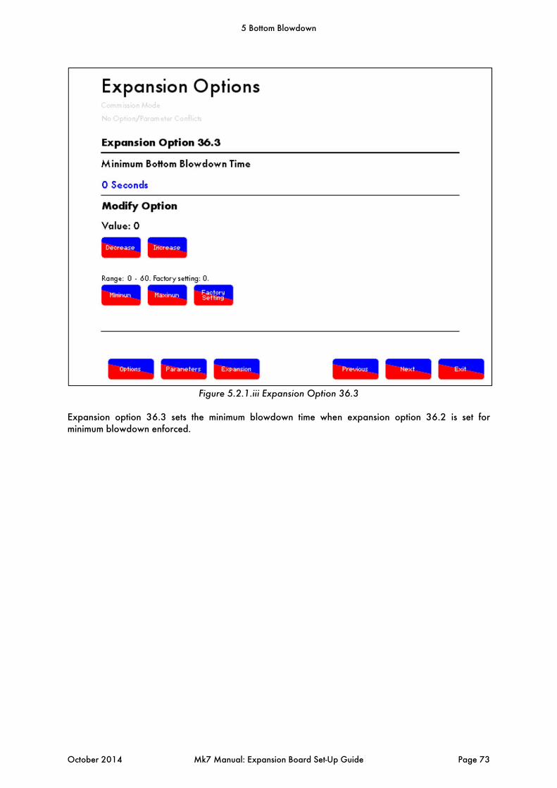
Figure 5.2.1.iii Expansion Option 36.3
Expansion option 36.3 sets the minimum blowdown time when expansion option 36.2 is set for minimum blowdown enforced.
5 Bottom Blowdown
October 2014 Mk7 Manual: Expansion Board Set-Up Guide Page 73

Figure 5.2.1.iv Expansion Options
Expansion option 36.4 allows the user to define the maximum steam production for the boiler so that the M.M. can use this rating to calculate the ratio of time decreases allowed in bottom blowdown time reduction according to the steam production.
5 Bottom Blowdown
Page 74 Mk7 Manual: Expansion Board Set-Up Guide October 2014
5.2.2 Commissioning Bottom Blowdown Module with M.M.
For a new installation, after checking the wiring, performing safety installation checks, and settings the options, parameters and expansion options, the order of commissioning the burner must follow:
1. Commission bottom blowdown module 2. Commission water level probes 3. Commission fuel to air ratio 4. Re-commission water level probes at operating temperature/pressure
The bottom blowdown module will be configured for battery operation with 35degrees from closed for the parked position. If changes are required, please refer to section 5.2.2 for how to set-up the bottom blowdown module with the bottom blowdown configurator. There are 4 expansion options to configure the bottom blowdown.
5 Bottom Blowdown
October 2014 Mk7 Manual: Expansion Board Set-Up Guide Page 75

Figure 5.2.2.i Bottom Blowdown Button
Once the expansion options have been configured for bottom blowdown, the will appear in the Commission Mode screen shown in Figure 5.2.2.i. Press this button to set the closed and open positions for the bottom blowdown valve as well as to test the battery back-up operation.
5 Bottom Blowdown
Page 76 Mk7 Manual: Expansion Board Set-Up Guide October 2014
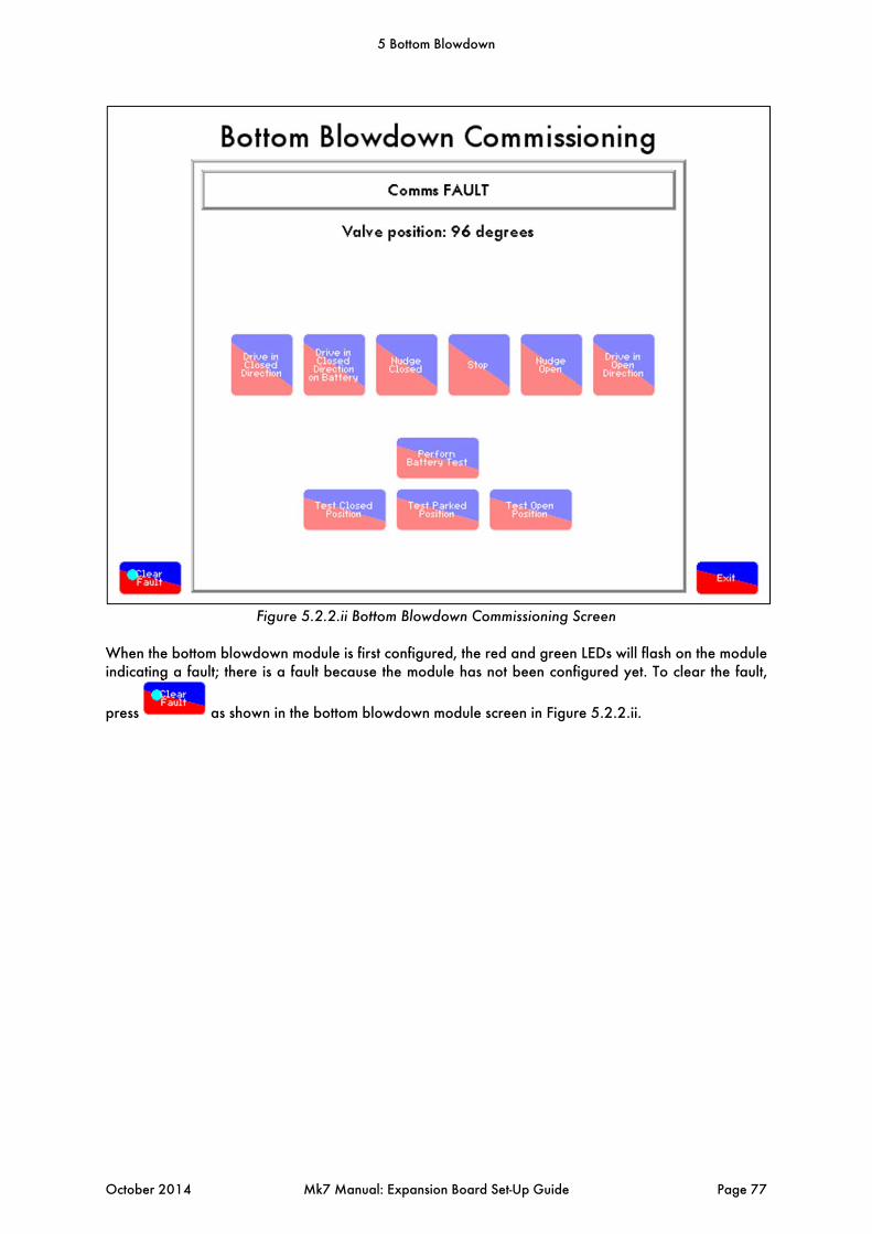
Figure 5.2.2.ii Bottom Blowdown Commissioning Screen
When the bottom blowdown module is first configured, the red and green LEDs will flash on the module indicating a fault; there is a fault because the module has not been configured yet. To clear the fault,
press as shown in the bottom blowdown module screen in Figure 5.2.2.ii.
5 Bottom Blowdown
October 2014 Mk7 Manual: Expansion Board Set-Up Guide Page 77
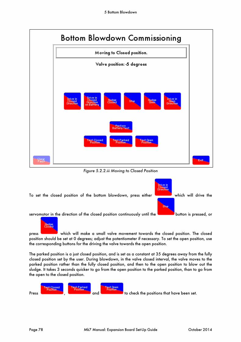
Figure 5.2.2.iii Moving to Closed Position
To set the closed position of the bottom blowdown, press either which will drive the
servomotor in the direction of the closed position continuously until the button is pressed, or
press which will make a small valve movement towards the closed position. The closed position should be set at 0 degrees; adjust the potentiometer if necessary. To set the open position, use the corresponding buttons for the driving the valve towards the open position.
The parked position is a just closed position, and is set as a constant at 35 degrees away from the fully closed position set by the user. During blowdown, in the valve closed interval, the valve moves to the parked position rather than the fully closed position, and then to the open position to blow out the sludge. It takes 3 seconds quicker to go from the open position to the parked position, than to go from the open to the closed position.
Press , and to check the positions that have been set.
5 Bottom Blowdown
Page 78 Mk7 Manual: Expansion Board Set-Up Guide October 2014
5.2.3 Battery Test
Pressing will the move the valve position towards the close position by using the battery power. A working battery will have 13V + in the cells, if this falls below 12.4V, there will not be enough voltage in the battery to drive the valve to the closed position should a power failure occurs.
To test the battery operation, drive the valve to the closed position, then press . The valve is then opened to the parked position using mains power, and then it is driven to the closed position using the battery power to test the battery. If the battery cannot drive the valve to the closed position, a 24V fault will appear.
The bottom blowdown module is now commissioned, press and then proceed to commission the water level probes, see section 2.3.1. After the M.M. has been commissioned for water level probes and fuel-to-air ratio, the timings and intervals of the bottom blowdown can be set.
5 Bottom Blowdown
October 2014 Mk7 Manual: Expansion Board Set-Up Guide Page 79
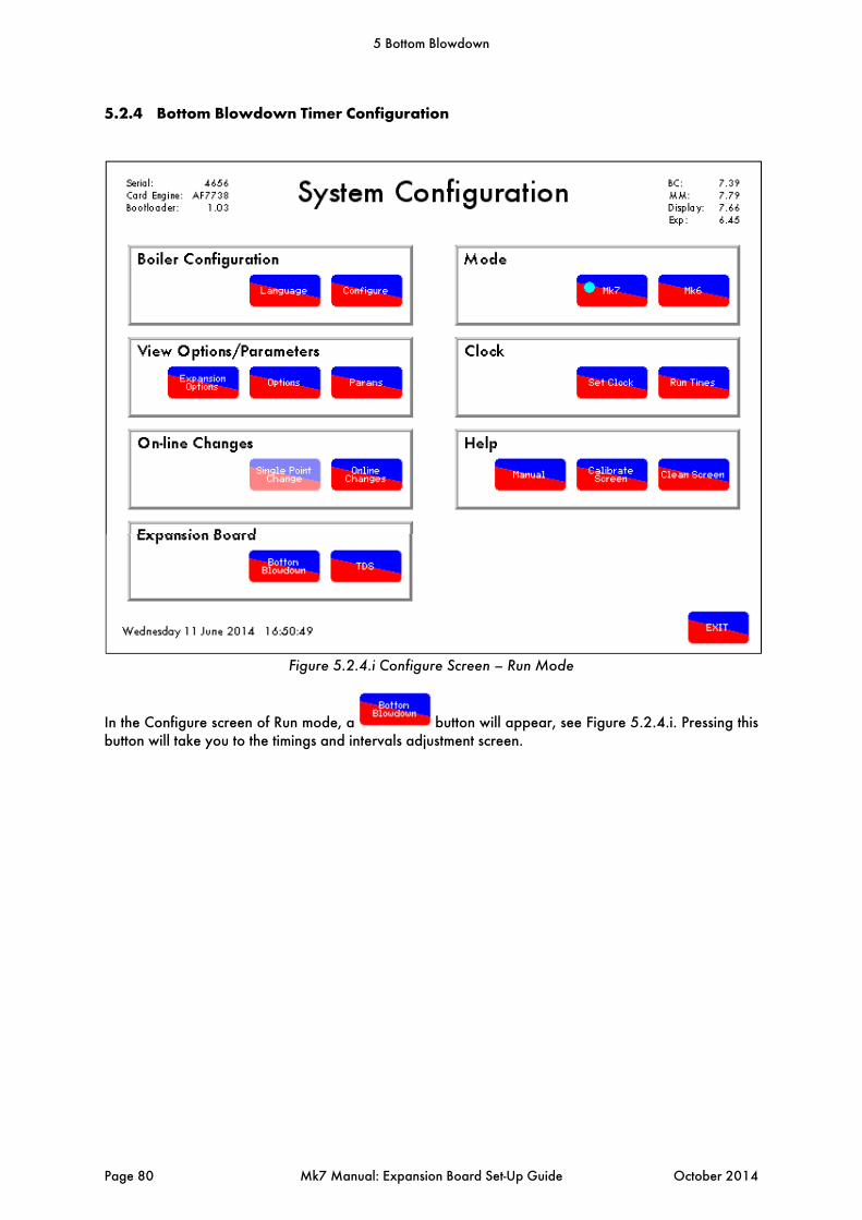
5.2.4 Bottom Blowdown Timer Configuration
Figure 5.2.4.i Configure Screen – Run Mode
In the Configure screen of Run mode, a button will appear, see Figure 5.2.4.i. Pressing this button will take you to the timings and intervals adjustment screen.
5 Bottom Blowdown
Page 80 Mk7 Manual: Expansion Board Set-Up Guide October 2014
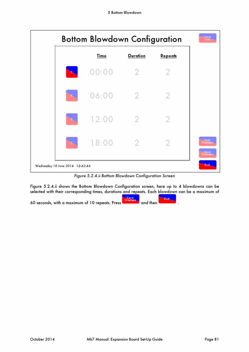
Figure 5.2.4.ii Bottom Blowdown Configuration Screen
Figure 5.2.4.ii shows the Bottom Blowdown Configuration screen, here up to 4 blowdowns can be selected with their corresponding times, durations and repeats. Each blowdown can be a maximum of
60 seconds, with a maximum of 10 repeats. Press and then .
5 Bottom Blowdown
October 2014 Mk7 Manual: Expansion Board Set-Up Guide Page 81
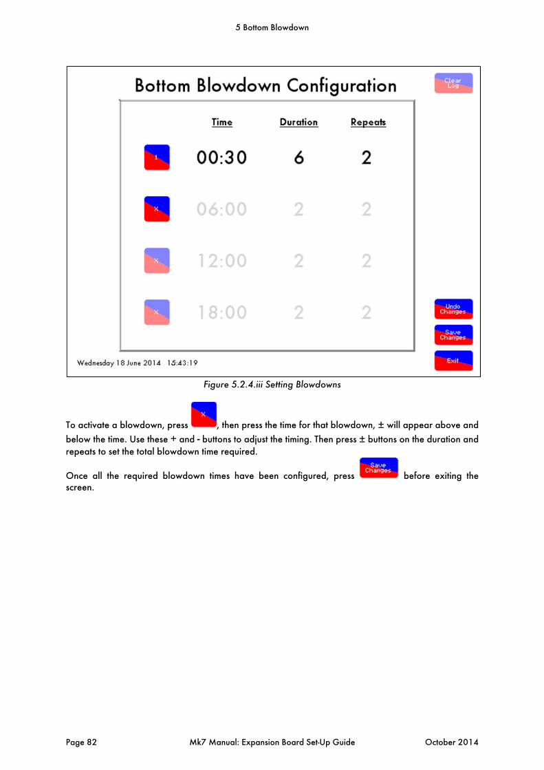
Figure 5.2.4.iii Setting Blowdowns
To activate a blowdown, press , then press the time for that blowdown, ± will appear above and
below the time. Use these + and - buttons to adjust the timing. Then press ± buttons on the duration and repeats to set the total blowdown time required.
Once all the required blowdown times have been configured, press before exiting the screen.
5 Bottom Blowdown
Page 82 Mk7 Manual: Expansion Board Set-Up Guide October 2014
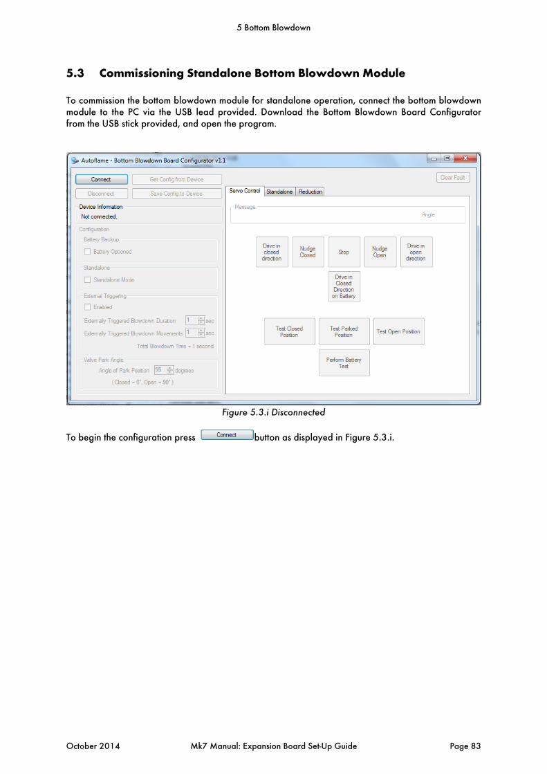
5.3 Commissioning Standalone Bottom Blowdown Module
To commission the bottom blowdown module for standalone operation, connect the bottom blowdown module to the PC via the USB lead provided. Download the Bottom Blowdown Board Configurator from the USB stick provided, and open the program.
Figure 5.3.i Disconnected
To begin the configuration press button as displayed in Figure 5.3.i.
5 Bottom Blowdown
October 2014 Mk7 Manual: Expansion Board Set-Up Guide Page 83
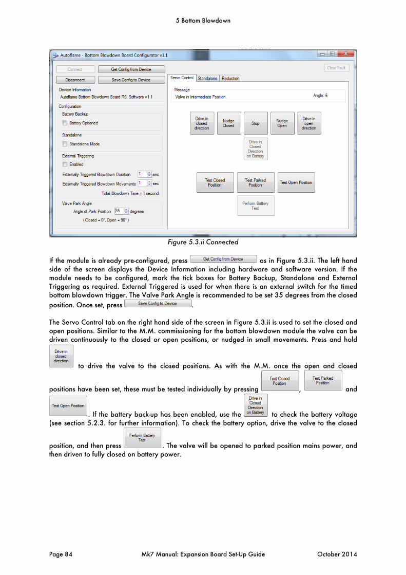
Figure 5.3.ii Connected
If the module is already pre-configured, press as in Figure 5.3.ii. The left hand side of the screen displays the Device Information including hardware and software version. If the module needs to be configured, mark the tick boxes for Battery Backup, Standalone and External Triggering as required. External Triggered is used for when there is an external switch for the timed bottom blowdown trigger. The Valve Park Angle is recommended to be set 35 degrees from the closed
position. Once set, press . The Servo Control tab on the right hand side of the screen in Figure 5.3.ii is used to set the closed and open positions. Similar to the M.M. commissioning for the bottom blowdown module the valve can be driven continuously to the closed or open positions, or nudged in small movements. Press and hold
to drive the valve to the closed positions. As with the M.M. once the open and closed
positions have been set, these must be tested individually by pressing , and
. If the battery back-up has been enabled, use the to check the battery voltage (see section 5.2.3. for further information). To check the battery option, drive the valve to the closed
position, and then press . The valve will be opened to parked position mains power, and then driven to fully closed on battery power.
5 Bottom Blowdown
Page 84 Mk7 Manual: Expansion Board Set-Up Guide October 2014
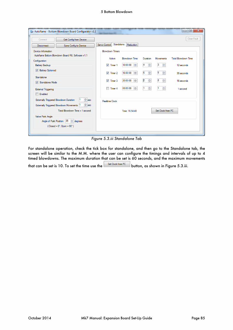
Figure 5.3.iii Standalone Tab
For standalone operation, check the tick box for standalone, and then go to the Standalone tab, the screen will be similar to the M.M. where the user can configure the timings and intervals of up to 4 timed blowdowns. The maximum duration that can be set is 60 seconds, and the maximum movements
that can be set is 10. To set the time use the button, as shown in Figure 5.3.iii.
5 Bottom Blowdown
October 2014 Mk7 Manual: Expansion Board Set-Up Guide Page 85
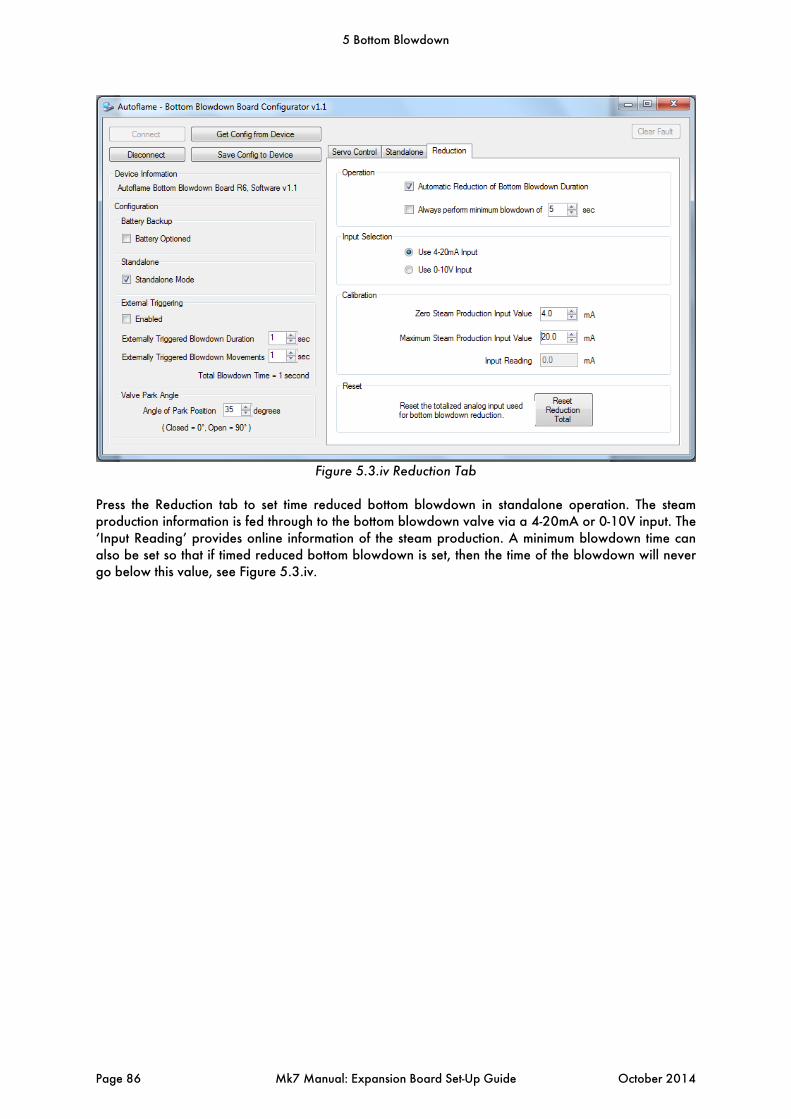
Figure 5.3.iv Reduction Tab
Press the Reduction tab to set time reduced bottom blowdown in standalone operation. The steam production information is fed through to the bottom blowdown valve via a 4-20mA or 0-10V input. The ‘Input Reading’ provides online information of the steam production. A minimum blowdown time can also be set so that if timed reduced bottom blowdown is set, then the time of the blowdown will never go below this value, see Figure 5.3.iv.
5 Bottom Blowdown
Page 86 Mk7 Manual: Expansion Board Set-Up Guide October 2014
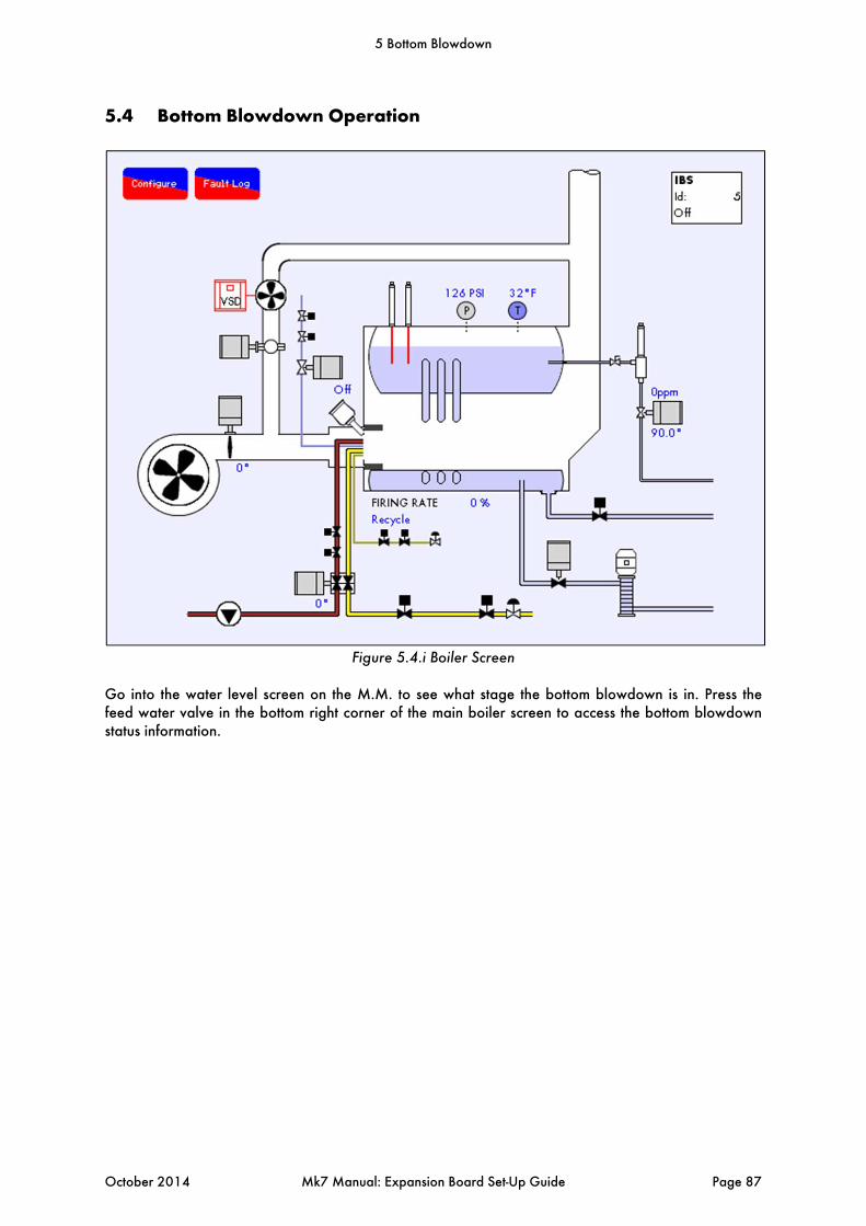
5.4 Bottom Blowdown Operation
Figure 5.4.i Boiler Screen
Go into the water level screen on the M.M. to see what stage the bottom blowdown is in. Press the feed water valve in the bottom right corner of the main boiler screen to access the bottom blowdown status information.
5 Bottom Blowdown
October 2014 Mk7 Manual: Expansion Board Set-Up Guide Page 87
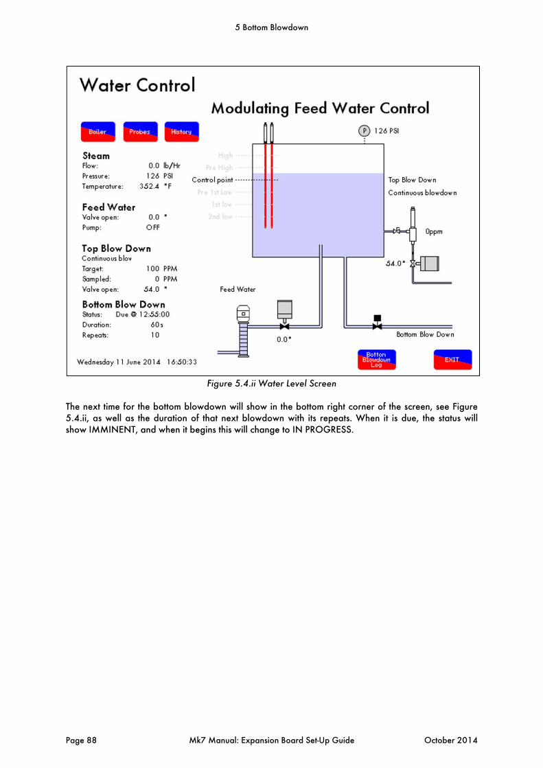
Figure 5.4.ii Water Level Screen
The next time for the bottom blowdown will show in the bottom right corner of the screen, see Figure 5.4.ii, as well as the duration of that next blowdown with its repeats. When it is due, the status will show IMMINENT, and when it begins this will change to IN PROGRESS.
5 Bottom Blowdown
Page 88 Mk7 Manual: Expansion Board Set-Up Guide October 2014
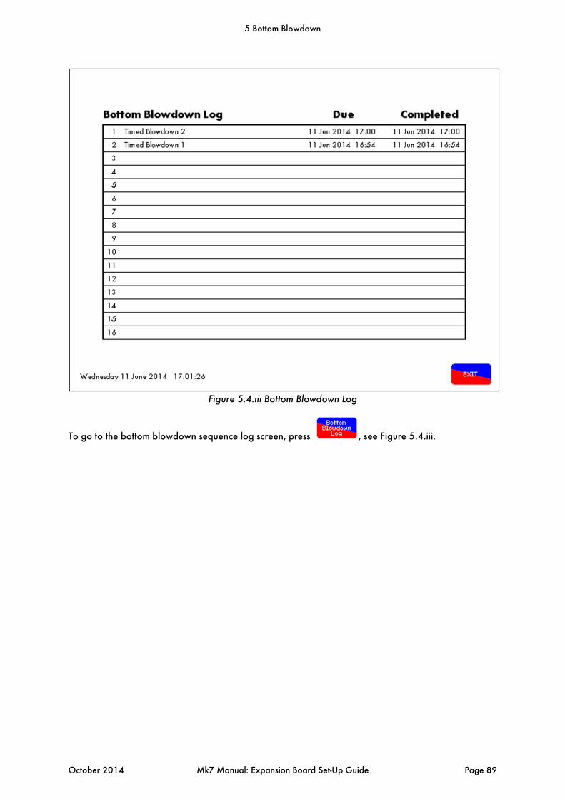
Figure 5.4.iii Bottom Blowdown Log
To go to the bottom blowdown sequence log screen, press , see Figure 5.4.iii.
5 Bottom Blowdown
October 2014 Mk7 Manual: Expansion Board Set-Up Guide Page 89
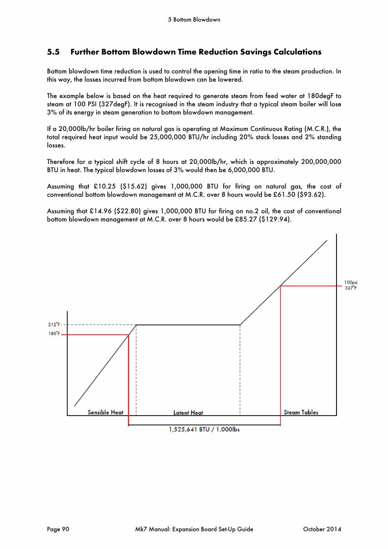
5.5 Further Bottom Blowdown Time Reduction Savings Calculations
Bottom blowdown time reduction is used to control the opening time in ratio to the steam production. In this way, the losses incurred from bottom blowdown can be lowered. The example below is based on the heat required to generate steam from feed water at 180degF to steam at 100 PSI (327degF). It is recognised in the steam industry that a typical steam boiler will lose 3% of its energy in steam generation to bottom blowdown management. If a 20,000lb/hr boiler firing on natural gas is operating at Maximum Continuous Rating (M.C.R.), the total required heat input would be 25,000,000 BTU/hr including 20% stack losses and 2% standing losses. Therefore for a typical shift cycle of 8 hours at 20,000lb/hr, which is approximately 200,000,000 BTU in heat. The typical blowdown losses of 3% would then be 6,000,000 BTU. Assuming that £10.25 ($15.62) gives 1,000,000 BTU for firing on natural gas, the cost of conventional bottom blowdown management at M.C.R. over 8 hours would be £61.50 ($93.62). Assuming that £14.96 ($22.80) gives 1,000,000 BTU for firing on no.2 oil, the cost of conventional bottom blowdown management at M.C.R. over 8 hours would be £85.27 ($129.94).
5 Bottom Blowdown
Page 90 Mk7 Manual: Expansion Board Set-Up Guide October 2014

In the example below, all savings are based on a 20,000lb/hr boiler operating over a 24 hour period for 8 hours at M.C.R., for 8 hours at 20% of M.C.R.. and 8 hours standby (banked). 8 hours High Fire, 8 hours Low Fire, 8 hours Standby – Blowdown without open time adjustment to
evaporation rate:
Natural Gas (£10.25/1MBTU) No.2 Oil (£14.96/1MBTU)
Average Steam Cost £19.22/1000lb £26.20/1000lb
Steam Production 144,538 lbs/day 145,042 lbs/day
Cost to Run Boiler (day) £2,460 /day £3,374.98 /day
Cost to Run Boiler (year) £897,900 /year £1,231,866 /year
8 hours High Fire, 8 hours Low Fire, 8 hours Standby – with open time adjustment to evaporation
rate:
Natural Gas (£10.25/1MBTU)
No.2 Oil (£14.96/1MBTU)
Average Steam Cost £17.23 / 1000 lb £ 23.49 /1000lb
Steam Production 148,571 lbs / day 149,136 /day
Cost to Run Boiler (day) £2,460 / day £3,374.98 /day
Cost to Run Boiler (year) £897,900 / year £1,231,866 /year
Steam Production 52,756,302 lb/year 52,940,336 lb/year
From this data, and keeping the same fuel consumption as before, using the reduced time bottom blowdown would give savings:
Typical Annual Savings (Gas) £25,373.49Typical Annual Savings (Oil) £35,101.27
5 Bottom Blowdown
October 2014 Mk7 Manual: Expansion Board Set-Up Guide Page 91
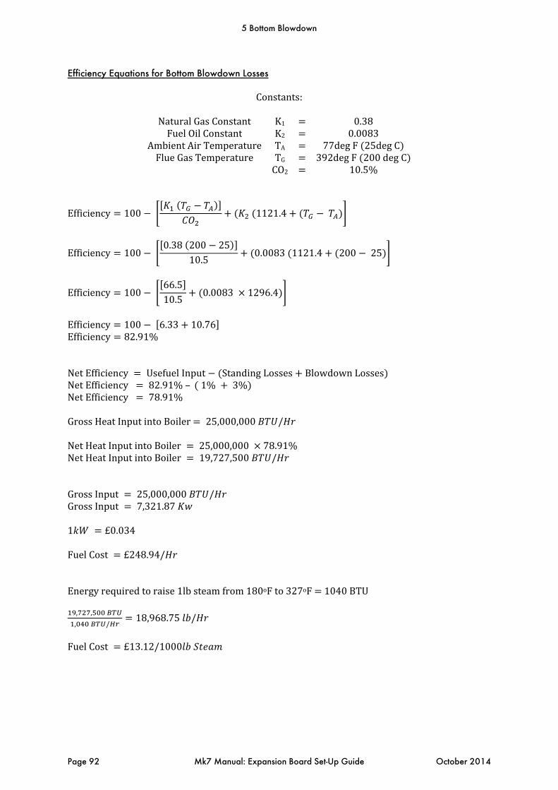
Efficiency Equations for Bottom Blowdown Losses
Constants:
NaturalGasConstant K1 0.38FuelOilConstant K2 0.0083
AmbientAirTemperature TA 77degF 25degC FlueGasTemperature TG 392degF 200degC
CO2 10.5%
Efficiency 100
1121.4
Efficiency 100 0.38 200 25
10.50.0083 1121.4 200 25
Efficiency 100 66.510.5
0.0083 1296.4
Efficiency 100 6.33 10.76 Efficiency 82.91%NetEfficiency UsefuelInput StandingLosses BlowdownLosses NetEfficiency 82.91%– 1% 3% NetEfficiency 78.91%
GrossHeatInputintoBoiler 25,000,000 /
NetHeatInputintoBoiler 25,000,000 78.91%NetHeatInputintoBoiler 19,727,500 / GrossInput 25,000,000 / GrossInput 7,321.87
1 £0.034
FuelCost £248.94/
Energyrequiredtoraise1lbsteamfrom180oFto327oF 1040BTU, ,
, /18,968.75 /
FuelCost £13.12/1000
5 Bottom Blowdown
Page 92 Mk7 Manual: Expansion Board Set-Up Guide October 2014
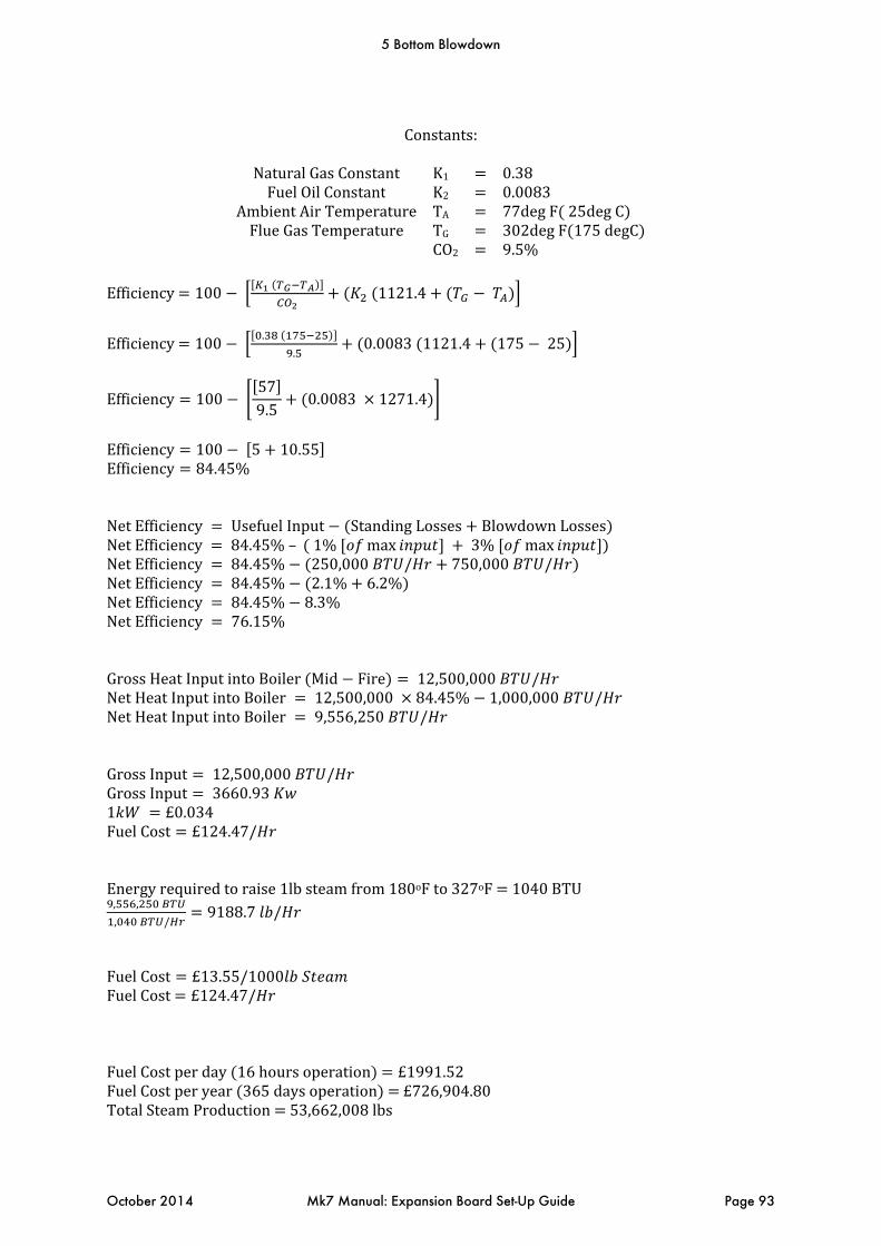
Constants:
NaturalGasConstant K1 0.38FuelOilConstant K2 0.0083
AmbientAirTemperature TA 77degF 25degC FlueGasTemperature TG 302degF 175degC
CO2 9.5%
Efficiency 100
1121.4
Efficiency 100 .
.0.0083 1121.4 175 25
Efficiency 100 579.5
0.0083 1271.4
Efficiency 100 5 10.55 Efficiency 84.45%NetEfficiency UsefuelInput StandingLosses BlowdownLosses NetEfficiency 84.45%– 1% max 3% max NetEfficiency 84.45% 250,000 / 750,000 / NetEfficiency 84.45% 2.1% 6.2% NetEfficiency 84.45% 8.3%NetEfficiency 76.15%GrossHeatInputintoBoiler Mid Fire 12,500,000 / NetHeatInputintoBoiler 12,500,000 84.45% 1,000,000 / NetHeatInputintoBoiler 9,556,250 / GrossInput 12,500,000 / GrossInput 3660.93 1 £0.034FuelCost £124.47/ Energyrequiredtoraise1lbsteamfrom180oFto327oF 1040BTU, ,
, /9188.7 /
FuelCost £13.55/1000 FuelCost £124.47/ FuelCostperday 16hoursoperation £1991.52FuelCostperyear 365daysoperation £726,904.80TotalSteamProduction 53,662,008lbs
5 Bottom Blowdown
October 2014 Mk7 Manual: Expansion Board Set-Up Guide Page 93

Constants:
NaturalGasConstant K1 0.38FuelOilConstant K2 0.0083
AmbientAirTemperature TA 77degF 25degC FlueGasTemperature TG 302degF 175degC
CO2 9.5%
Efficiency 100
1121.4
Efficiency 100 0.38 175 25
9.50.0083 1121.4 175 25
Efficiency 100 579.5
0.0083 1271.4
Efficiency 100 5 10.55 Efficiency 84.45%Byhalvingblowdownlosses:GrossHeatInputintoBoiler Mid Fire 12,500,000 / NetEfficency UsefulInput StandingLosses BlowdownLosses NetEfficiency 84.45%– 1% max 1.5% max NetEfficiency 84.45% 250,000 / 375,000 / NetEfficiency 84.45% 2.1% 3% NetEfficiency 84.45% 5.1%NetEfficiency 79.45%GrossHeatInputintoBoiler MidFire 12,500,000 / NetHeatInputintoBoiler 12,500,000 79.45%NetHeatInputintoBoiler 9,931,250 / GrossInput 12,500,000 / GrossInput 3660.93 1 £0.034FuelCost £124.47/ Energyrequiredtoraise1lbsteamfrom180oFto327oF 1040BTU, ,
, /9549.28 /
FuelCost £13.03/1000 FuelCost £124.47/ FuelCostperday 16hoursoperation £1991.52FuelCostperyear 365daysoperation £726,904.80TotalSteamProduction 55,767,795lbs
5 Bottom Blowdown
Page 94 Mk7 Manual: Expansion Board Set-Up Guide October 2014

Therefore:Peryear withan50%boileroutput :TotalSteamProductionwithStandardBlowdown 53,662,008lbsTotalSteamProductionwithTimeAdjustedBlowdown 55,767,795lbsAnadditional2,105,787lbsofsteamproducedforthesamecost.Ifproducingthesameamountofsteamthefollowingsavingisdeduced:
£0.01303x2,105,787 £27.438.40savings3.77%overallsavings
5 Bottom Blowdown
October 2014 Mk7 Manual: Expansion Board Set-Up Guide Page 95

5.6 Shunt Switch
5.6.1 Shunt Switch Philosophy
The ability to implement a controlled by-pass of the low water cut off’s during a manual water column blowdown, boiler blowdown or evaporation test is available on the Mk7 M.M. with water level control. This is incorporated into the Autoflame controller so as to avoid the requirement for any additional push buttons/key switches on the control panel. The operation of the shunt switch can only be accessed in Mk6 mode. Please follow this procedure: 1. While the burner is either firing or in the standby state, press the ‘Water Level’ and ‘Enter Memory’ buttons simultaneously. 2. The Mk.6 screen will show “Implement level Control Test Procedure”. 3. The operator will have to either confirm that he wanted to proceed by pressing ‘Water Level’ and ‘Enter Memory’ simultaneously or press ‘Run’ to exit. 4. If the operator proceeded to press the ‘Water Level’ and ‘Enter Memory’ button, the Mk.6 screen would then display ‘Feed Water Valve Shut’ and close the feed water valve. 5. The burner would continue to operate. At this time the operator would either let the water evaporate automatically or physically blow down the water column or boiler. A user-definable amount of time (time A) is set in expansion option 25.1, during which time the 1st Low must be reached. If not, the burner will revert back to the run condition. 6. The 1st Low Alarm would be initiated and the alarm would sound. The operator has the option of muting the alarm. The burner continues to operate. 7. The operator would continue to decrease the water level in the column or boiler or allow the water to continue evaporating. A user-definable amount of time (time B) is set in expansion option 25.2, during which time the 2nd Low must be reached. If not, the burner will turn off. 8. The 2nd Low Alarm would be initiated and the alarm would sound. The operator again has the option of muting the alarm. The burner continues to operate. 9. 3 seconds after the 2nd Low Alarm has been initiated the Mk.6 screen would display ‘Feed Water Valve Open’. The water level would start to increase. 10. The Mk.6 would expect to see the water level rise above the 2nd Low Level within 300 seconds (default value) or time B of the valve opening. Should the level not increase a 2nd Low Alarm will be initiated, causing the burner to turn off and a lockout to occur, requiring a manual reset to recycle the system. 11. Once the water level increased above the 2nd Low Level the Mk.6 would allow a further 300 seconds (default value) or time A for the water level to rise above the 1st Low Level. Again should the level not increase a 1st Low Alarm will be initiated, causing the burner to turn off and an alarm to sound. The system would automatically recycle the system once the water level is above the 1st Low Level. 12. Once the level returns to above the 1st Low Level the screen would display ‘Test Complete, Normal Operating Level Restored’
5 Bottom Blowdown
Page 96 Mk7 Manual: Expansion Board Set-Up Guide October 2014
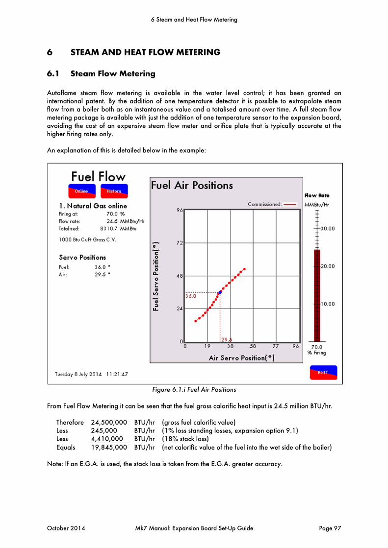
6 STEAM AND HEAT FLOW METERING
6.1 Steam Flow Metering
Autoflame steam flow metering is available in the water level control; it has been granted an international patent. By the addition of one temperature detector it is possible to extrapolate steam flow from a boiler both as an instantaneous value and a totalised amount over time. A full steam flow metering package is available with just the addition of one temperature sensor to the expansion board, avoiding the cost of an expensive steam flow meter and orifice plate that is typically accurate at the higher firing rates only. An explanation of this is detailed below in the example:
Figure 6.1.i Fuel Air Positions
From Fuel Flow Metering it can be seen that the fuel gross calorific heat input is 24.5 million BTU/hr.
Therefore 24,500,000 BTU/hr (gross fuel calorific value) Less 245,000 BTU/hr (1% loss standing losses, expansion option 9.1) Less 4,410,000 BTU/hr (18% stack loss) Equals 19,845,000 BTU/hr (net calorific value of the fuel into the wet side of the boiler)
Note: If an E.G.A. is used, the stack loss is taken from the E.G.A. greater accuracy.
6 Steam and Heat Flow Metering
October 2014 Mk7 Manual: Expansion Board Set-Up Guide Page 97
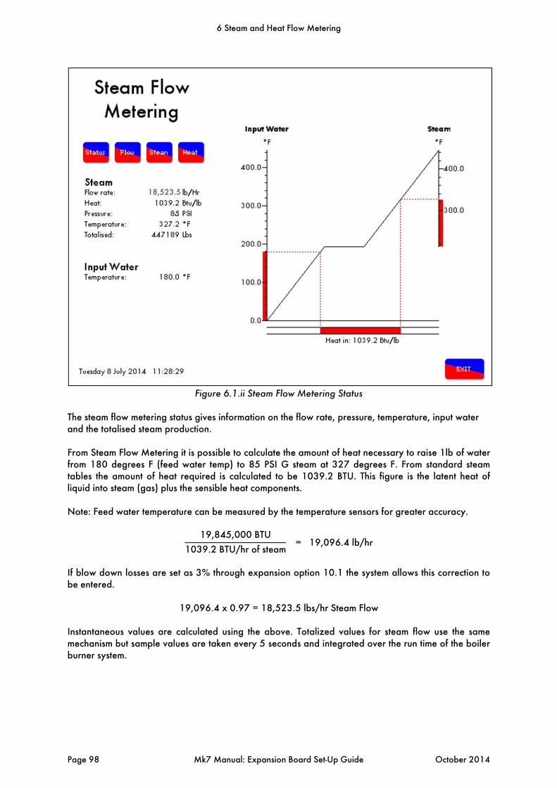
Figure 6.1.ii Steam Flow Metering Status
The steam flow metering status gives information on the flow rate, pressure, temperature, input water and the totalised steam production. From Steam Flow Metering it is possible to calculate the amount of heat necessary to raise 1lb of water from 180 degrees F (feed water temp) to 85 PSI G steam at 327 degrees F. From standard steam tables the amount of heat required is calculated to be 1039.2 BTU. This figure is the latent heat of liquid into steam (gas) plus the sensible heat components. Note: Feed water temperature can be measured by the temperature sensors for greater accuracy.
19,845,000 BTU
1039.2 BTU/hr of steam = 19,096.4 lb/hr
If blow down losses are set as 3% through expansion option 10.1 the system allows this correction to be entered.
19,096.4 x 0.97 = 18,523.5 lbs/hr Steam Flow Instantaneous values are calculated using the above. Totalized values for steam flow use the same mechanism but sample values are taken every 5 seconds and integrated over the run time of the boiler burner system.
18,523.5
6 Steam and Heat Flow Metering
Page 98 Mk7 Manual: Expansion Board Set-Up Guide October 2014

Figure 6.1.ii Steam Flow Rate History
The steam flow rate history screen logs the flow rate and totalised steam production for up to 24 hours.
6 Steam and Heat Flow Metering
October 2014 Mk7 Manual: Expansion Board Set-Up Guide Page 99
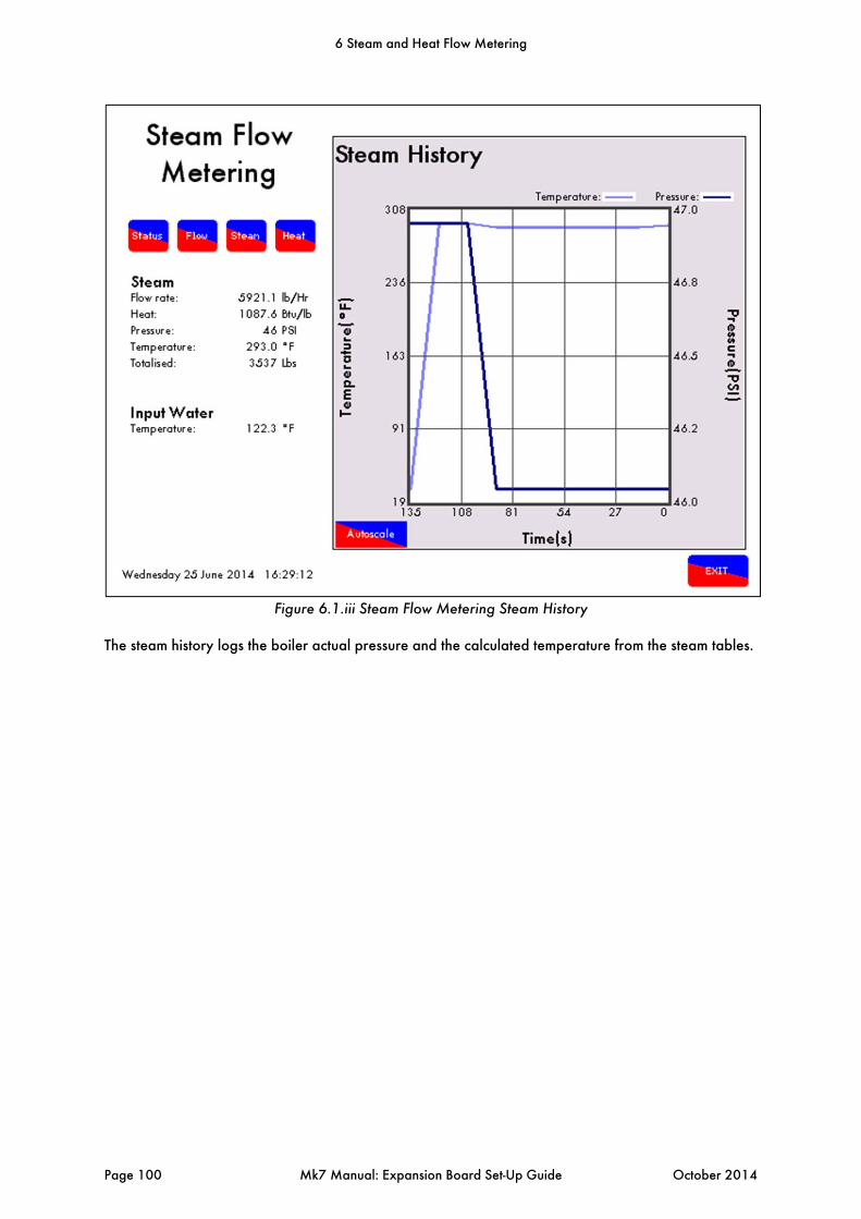
Figure 6.1.iii Steam Flow Metering Steam History
The steam history logs the boiler actual pressure and the calculated temperature from the steam tables.
6 Steam and Heat Flow Metering
Page 100 Mk7 Manual: Expansion Board Set-Up Guide October 2014

Figure 6.1.iv Steam Flow Metering Heat History
The heat history screen logs the input water temperature, steam temperature and the heat value for up to 24 hours.
6 Steam and Heat Flow Metering
October 2014 Mk7 Manual: Expansion Board Set-Up Guide Page 101
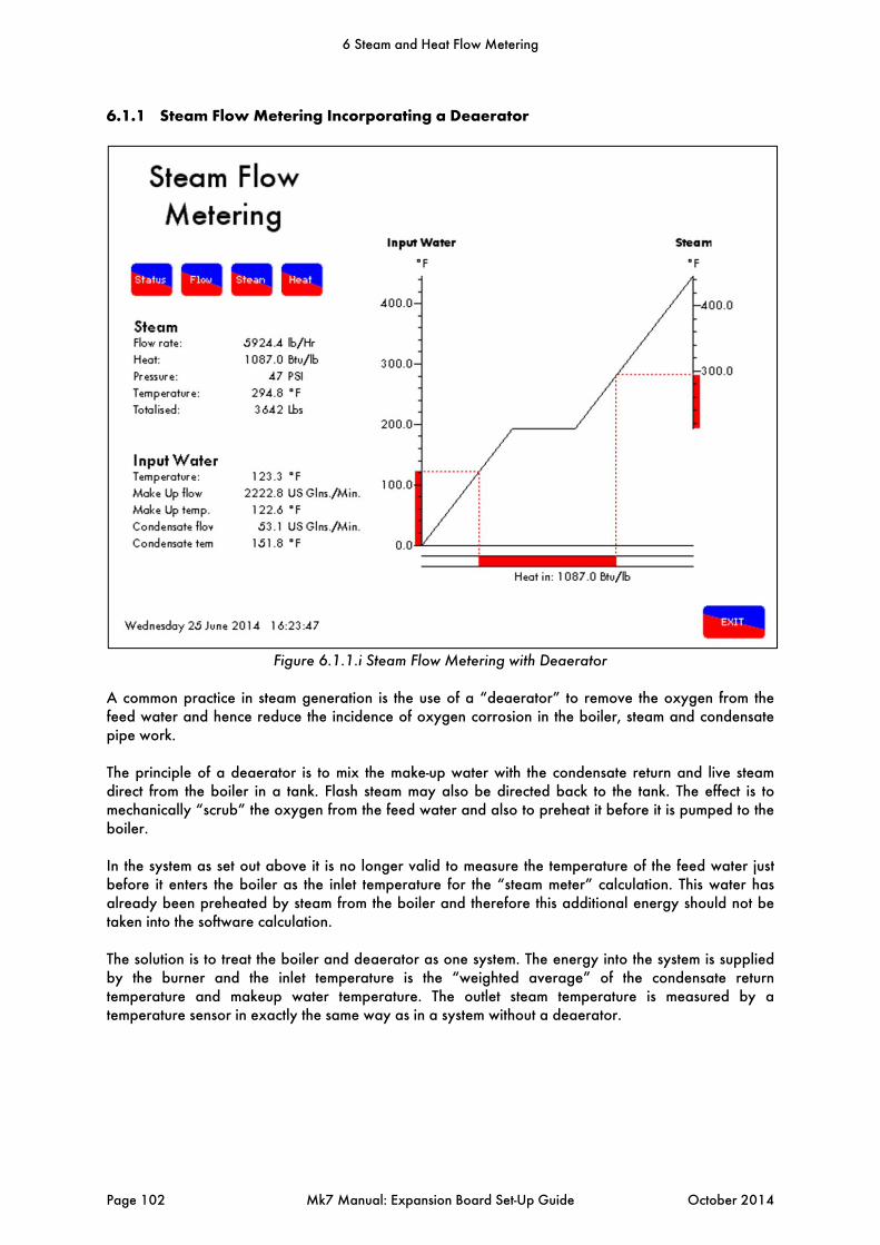
6.1.1 Steam Flow Metering Incorporating a Deaerator
Figure 6.1.1.i Steam Flow Metering with Deaerator
A common practice in steam generation is the use of a “deaerator” to remove the oxygen from the feed water and hence reduce the incidence of oxygen corrosion in the boiler, steam and condensate pipe work. The principle of a deaerator is to mix the make-up water with the condensate return and live steam direct from the boiler in a tank. Flash steam may also be directed back to the tank. The effect is to mechanically “scrub” the oxygen from the feed water and also to preheat it before it is pumped to the boiler. In the system as set out above it is no longer valid to measure the temperature of the feed water just before it enters the boiler as the inlet temperature for the “steam meter” calculation. This water has already been preheated by steam from the boiler and therefore this additional energy should not be taken into the software calculation. The solution is to treat the boiler and deaerator as one system. The energy into the system is supplied by the burner and the inlet temperature is the “weighted average” of the condensate return temperature and makeup water temperature. The outlet steam temperature is measured by a temperature sensor in exactly the same way as in a system without a deaerator.
6 Steam and Heat Flow Metering
Page 102 Mk7 Manual: Expansion Board Set-Up Guide October 2014
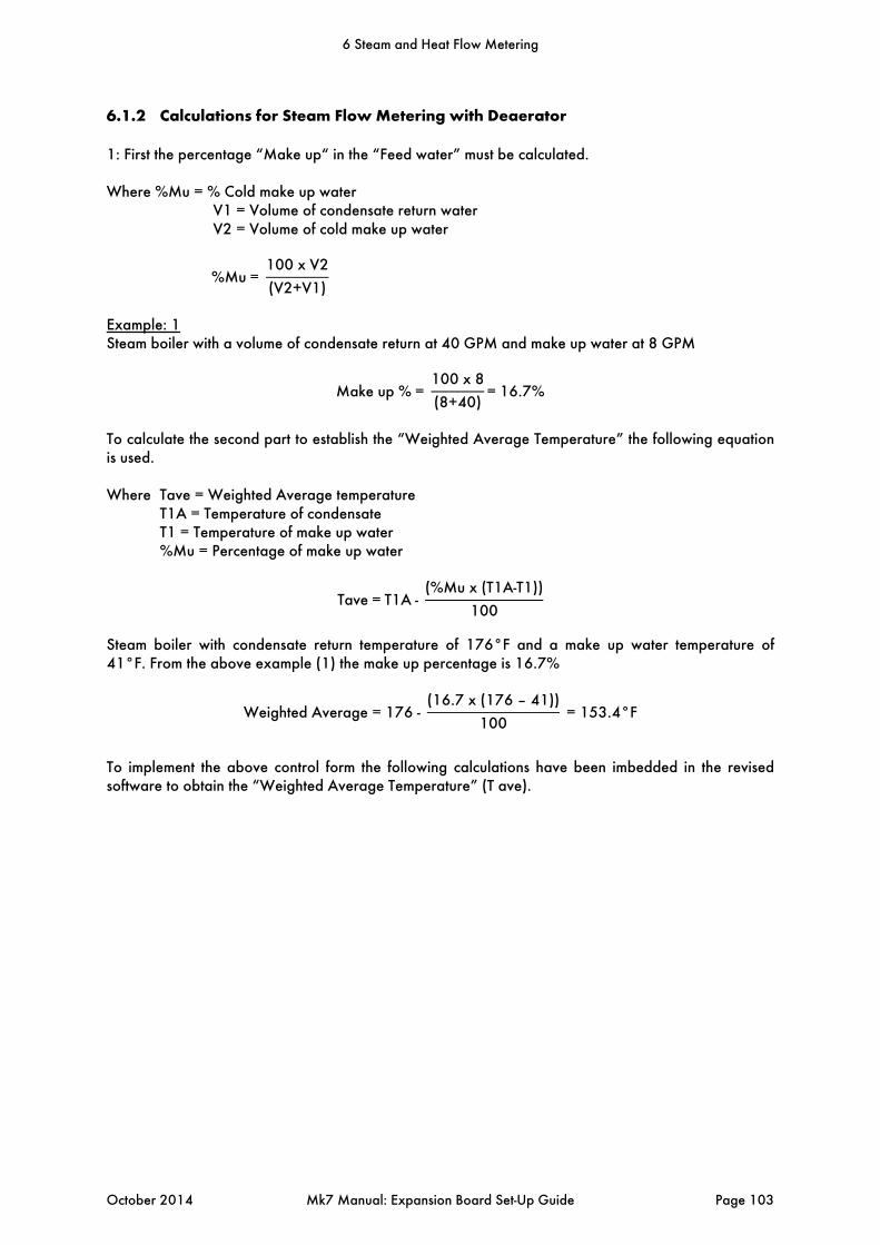
6.1.2 Calculations for Steam Flow Metering with Deaerator
1: First the percentage “Make up“ in the “Feed water” must be calculated. Where %Mu = % Cold make up water
V1 = Volume of condensate return water V2 = Volume of cold make up water
%Mu= 100 x V2
(V2+V1)
Example: 1 Steam boiler with a volume of condensate return at 40 GPM and make up water at 8 GPM
Make up %= 100 x 8
(8+40)=16.7%
To calculate the second part to establish the “Weighted Average Temperature” the following equation is used. Where Tave = Weighted Average temperature
T1A = Temperature of condensate T1 = Temperature of make up water %Mu = Percentage of make up water
Tave=T1A- (%Mu x (T1A-T1))
100
Steam boiler with condensate return temperature of 176°F and a make up water temperature of 41°F. From the above example (1) the make up percentage is 16.7%
Weighted Average = 176 - (16.7 x (176 – 41))
100 = 153.4°F
To implement the above control form the following calculations have been imbedded in the revised software to obtain the “Weighted Average Temperature” (T ave).
6 Steam and Heat Flow Metering
October 2014 Mk7 Manual: Expansion Board Set-Up Guide Page 103
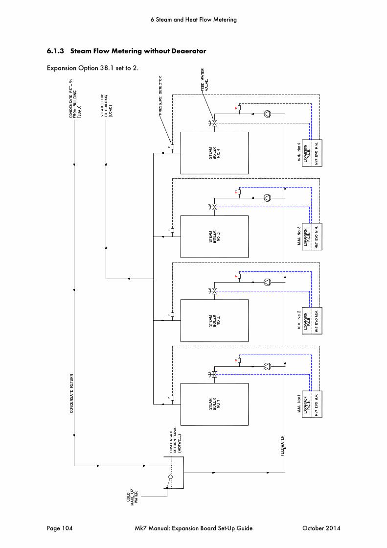
6.1.3 Steam Flow Metering without Deaerator
Expansion Option 38.1 set to 2.
6 Steam and Heat Flow Metering
Page 104 Mk7 Manual: Expansion Board Set-Up Guide October 2014
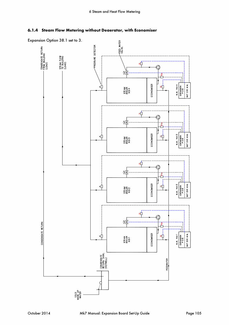
6.1.4 Steam Flow Metering without Deaerator, with Economiser
Expansion Option 38.1 set to 3.
6 Steam and Heat Flow Metering
October 2014 Mk7 Manual: Expansion Board Set-Up Guide Page 105
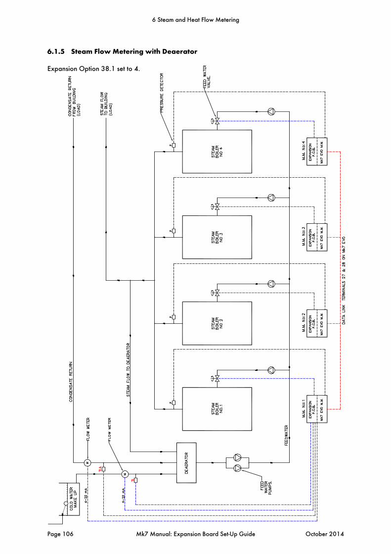
6.1.5 Steam Flow Metering with Deaerator
Expansion Option 38.1 set to 4.
6 Steam and Heat Flow Metering
Page 106 Mk7 Manual: Expansion Board Set-Up Guide October 2014

6.1.6 Steam Flow Metering with Deaerator and Economiser
Expansion Option 38.1 set to 5.
6 Steam and Heat Flow Metering
October 2014 Mk7 Manual: Expansion Board Set-Up Guide Page 107
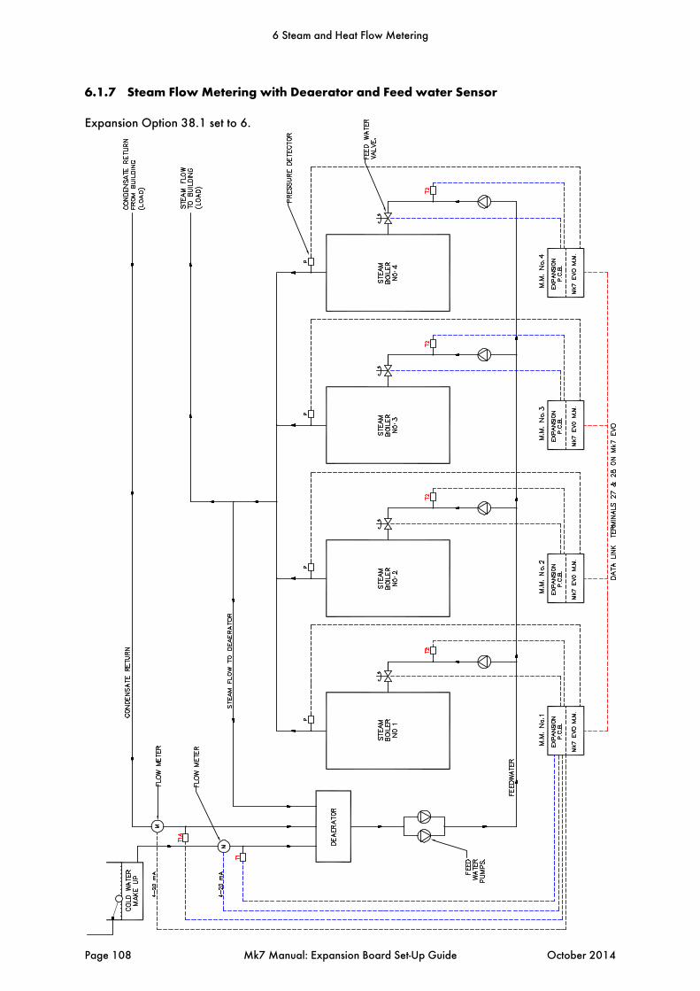
6.1.7 Steam Flow Metering with Deaerator and Feed water Sensor
Expansion Option 38.1 set to 6.
6 Steam and Heat Flow Metering
Page 108 Mk7 Manual: Expansion Board Set-Up Guide October 2014

6.2 Heat Flow Metering
Heat Flow Metering is simply measuring the amount of heat being transferred to the water by a hot water boiler. If we know the stack losses and the standing losses of the boiler at any moment then whatever energy is left over must be going into the water. From the E.G.A. stack losses = 100 – combustion efficiency Radiation losses are specific to the boiler, 1% radiation losses are typical for a packaged boiler operating at maximum continuous rating. The loss is constant regardless of boiler output so at 50% firing rate it would be 2% of the energy input. The total heat in at any time is given by the heat flow metering so we can calculate the instantaneous heat going into water. By integrating these values we can get a totalised value. 6.2.1 Calculation for Heat Output and Volume Flow
Efficiency% 100% StacklossRadiationLosses 100
FiringRate
UsefulHeatintoWater TotalHeatEfficiency
100
VolumeFlowinlbs/hr UsefulheatMBTU/Hr
SPHtBTU/lb/°F FlowTemp–ReturnTemp
VolumeFlowincuftHrVolumeFlowin lbs hr⁄
DensityofWateratReturnTemperature
Since1cuftHr 0.124676USG. P.M.
VolumeFlowinUSG. P.M. VolumeFlowincuftHr 0.124676
6 Steam and Heat Flow Metering
October 2014 Mk7 Manual: Expansion Board Set-Up Guide Page 109
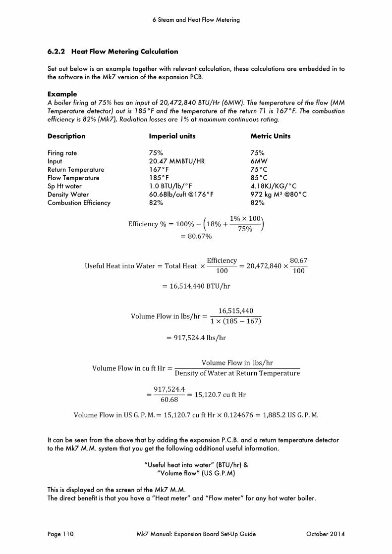
6.2.2 Heat Flow Metering Calculation
Set out below is an example together with relevant calculation, these calculations are embedded in to the software in the Mk7 version of the expansion PCB. Example A boiler firing at 75% has an input of 20,472,840 BTU/Hr (6MW). The temperature of the flow (MM Temperature detector) out is 185°F and the temperature of the return T1 is 167°F. The combustion efficiency is 82% (Mk7), Radiation losses are 1% at maximum continuous rating. Description Imperial units Metric Units Firing rate 75% 75% Input 20.47 MMBTU/HR 6MW Return Temperature 167°F 75°C Flow Temperature 185°F 85°C Sp Ht water 1.0 BTU/lb/°F 4.18KJ/KG/°C Density Water 60.68lb/cuft @176°F 972 kg M³ @80°C Combustion Efficiency 82% 82%
Efficiency% 100% 18%1% 10075%
80.67%
UsefulHeatintoWater TotalHeatEfficiency
10020,472,840
80.67100
16,514,440BTU/hr
VolumeFlowinlbs/hr 16,515,440
1 185 167
917,524.4lbs/hr
VolumeFlowincuftHrVolumeFlowin lbs hr⁄
DensityofWateratReturnTemperature
917,524.460.68
15,120.7cuftHr
VolumeFlowinUSG. P.M. 15,120.7cuftHr 0.124676 1,885.2USG. P. M.
It can be seen from the above that by adding the expansion P.C.B. and a return temperature detector to the Mk7 M.M. system that you get the following additional useful information.
“Useful heat into water” (BTU/hr) & “Volume flow” (US G.P.M)
This is displayed on the screen of the Mk7 M.M. The direct benefit is that you have a “Heat meter” and “Flow meter” for any hot water boiler.
6 Steam and Heat Flow Metering
Page 110 Mk7 Manual: Expansion Board Set-Up Guide October 2014
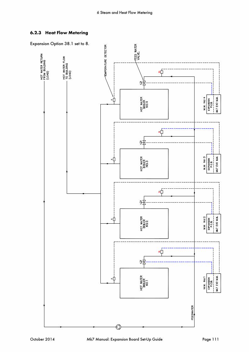
6.2.3 Heat Flow Metering
Expansion Option 38.1 set to 8.
6 Steam and Heat Flow Metering
October 2014 Mk7 Manual: Expansion Board Set-Up Guide Page 111
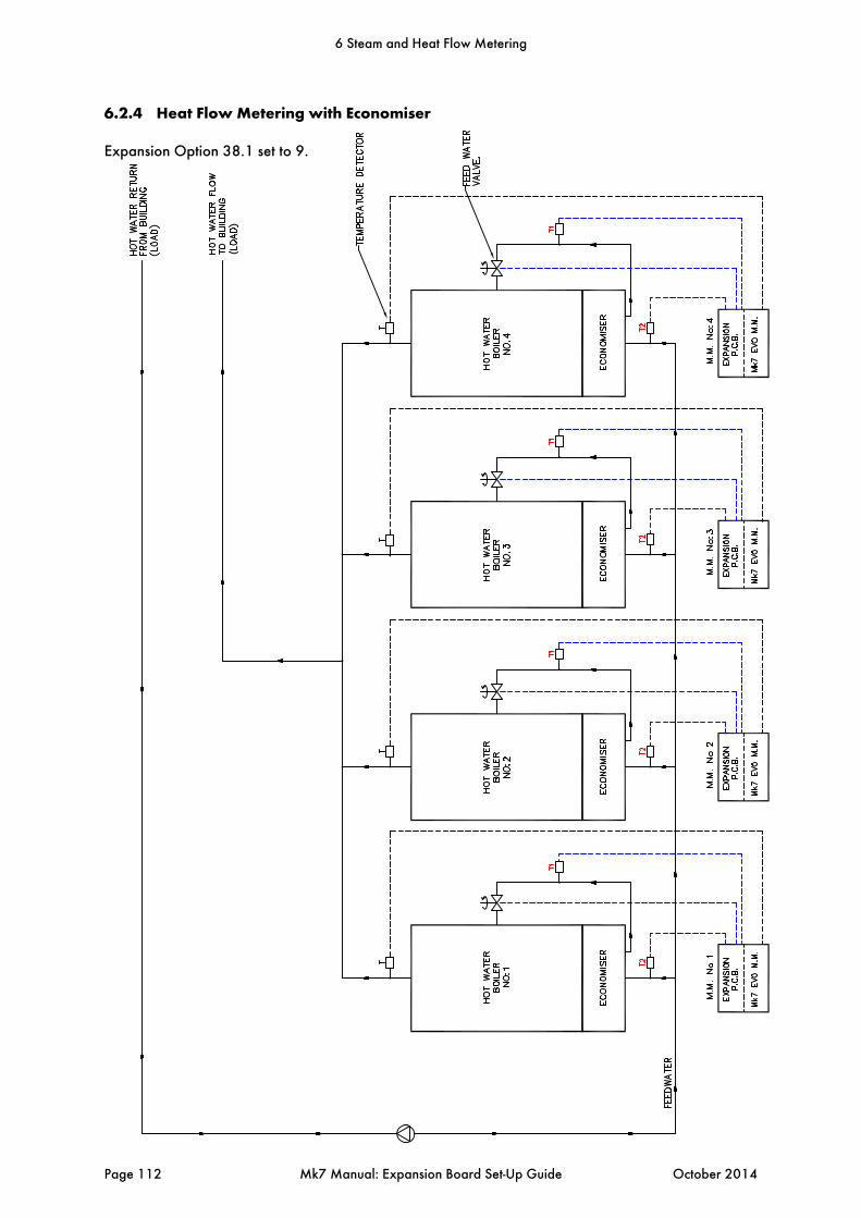
6.2.4 Heat Flow Metering with Economiser
Expansion Option 38.1 set to 9.
6 Steam and Heat Flow Metering
Page 112 Mk7 Manual: Expansion Board Set-Up Guide October 2014
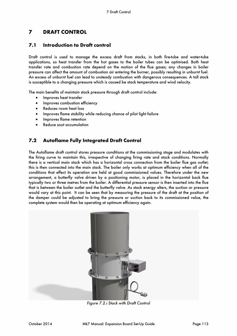
7 DRAFT CONTROL
7.1 Introduction to Draft control
Draft control is used to manage the excess draft from stacks, in both fire-tube and water-tube applications, so heat transfer from the hot gases to the boiler tubes can be optimised. Both heat transfer rate and combustion rate depend on the motion of the flue gases; any changes in boiler pressure can affect the amount of combustion air entering the burner, possibly resulting in unburnt fuel. An excess of unburnt fuel can lead to unsteady combustion with dangerous consequences. A tall stack is susceptible to a changing pressure which is caused be stack temperature and wind velocity. The main benefits of maintain stack pressure through draft control include:
Improves heat transfer Improves combustion efficiency Reduces room heat loss Improves flame stability while reducing chance of pilot light failure Improves flame retention Reduce soot accumulation
7.2 Autoflame Fully Integrated Draft Control
The Autoflame draft control stores pressure conditions at the commissioning stage and modulates with the firing curve to maintain this, irrespective of changing firing rate and stack conditions. Normally there is a vertical main stack which has a horizontal cross connection from the boiler flue gas outlet; this is then connected into the main stack. The boiler only works at optimum efficiency when all of the conditions that effect its operation are held at good commissioned values. Therefore under the new arrangement, a butterfly valve driven by a positioning motor, is placed in the horizontal back flue typically two or three metres from the boiler. A differential pressure sensor is then inserted into the flue that is between the boiler outlet and the butterfly valve. As stack energy alters, the suction or pressure would vary at this point. It can be seen that by measuring the pressure of the draft at the position of the damper could be adjusted to bring the pressure or suction back to its commissioned value, the complete system would then be operating at optimum efficiency again.
Figure 7.2.i Stack with Draft Control
7 Draft Control
October 2014 Mk7 Manual: Expansion Board Set-Up Guide Page 113
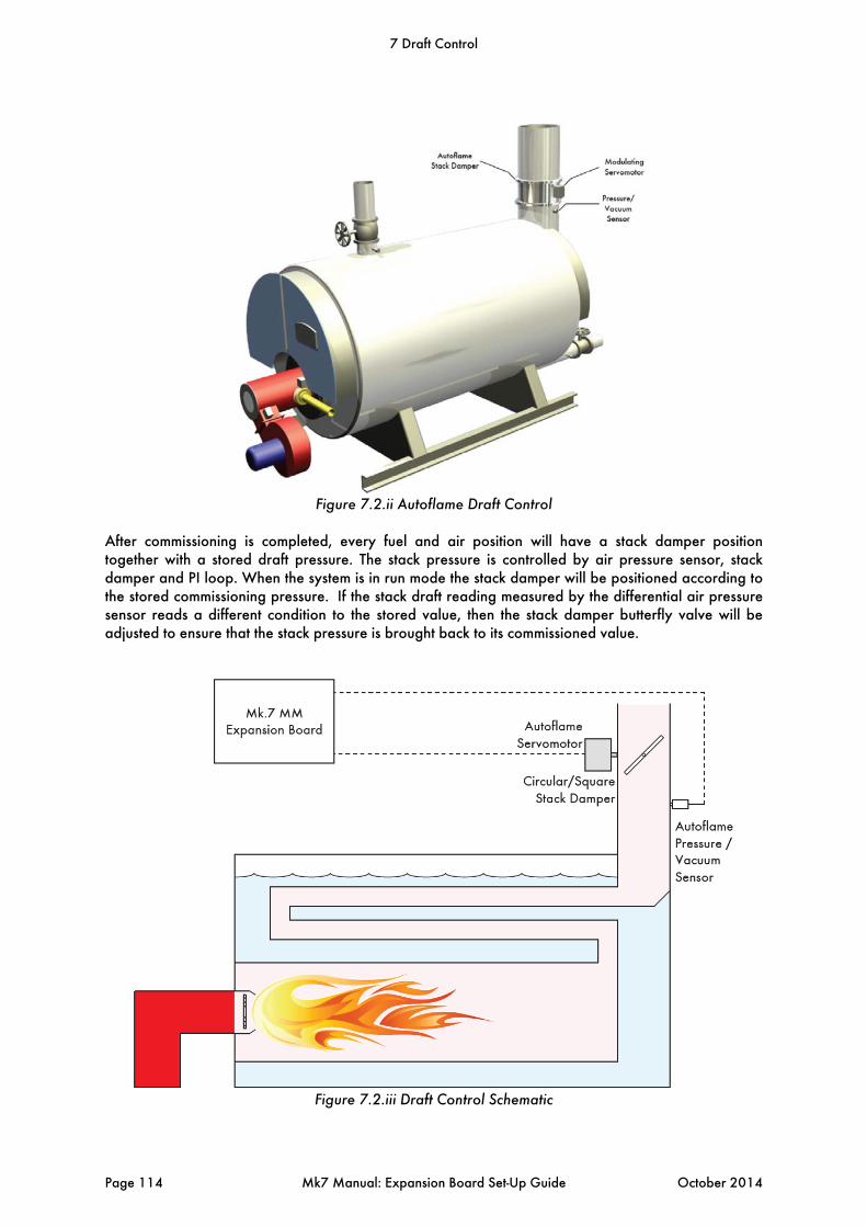
Figure 7.2.ii Autoflame Draft Control
After commissioning is completed, every fuel and air position will have a stack damper position together with a stored draft pressure. The stack pressure is controlled by air pressure sensor, stack damper and PI loop. When the system is in run mode the stack damper will be positioned according to the stored commissioning pressure. If the stack draft reading measured by the differential air pressure sensor reads a different condition to the stored value, then the stack damper butterfly valve will be adjusted to ensure that the stack pressure is brought back to its commissioned value.
Figure 7.2.iii Draft Control Schematic
7 Draft Control
Page 114 Mk7 Manual: Expansion Board Set-Up Guide October 2014
7.3 Set-Up
To maintain the stack pressure through the Autoflame draft control system, the following is required: Mk7 M.M. with Expansion Board Air Pressure Sensor MM70005 (SN 100 upwards) Industrial Servomotor
Note: A small or large servomotor can be used for smaller applications, however an industrial servomotor is recommended for the appropriate softened error checking for a large damper. If the site requires a new damper for draft control, please contact Autoflame Technical Support.
7.3.1 Terminals
The following terminals on the expansion board are used for the Autoflame draft control:
DPC Draft air pressure sensor (check)
DPS Draft air pressure sensor (signal)
DP- Draft pressure sensor & motorised draft control damper voltage –ve
DP+ Draft pressure sensor & motorised draft control damper voltage +ve
DPW Motorised draft control damper potentiometer wiper
DCI Motorised draft control damper servomotor – increase (output switched neutral)
DCD Motorised draft control damper servomotor – decrease (output switched neutral)
7.3.2 Draft Control Expansion Options
The draft control system can be configured through the following expansion options.
7 Draft Control
October 2014 Mk7 Manual: Expansion Board Set-Up Guide Page 115
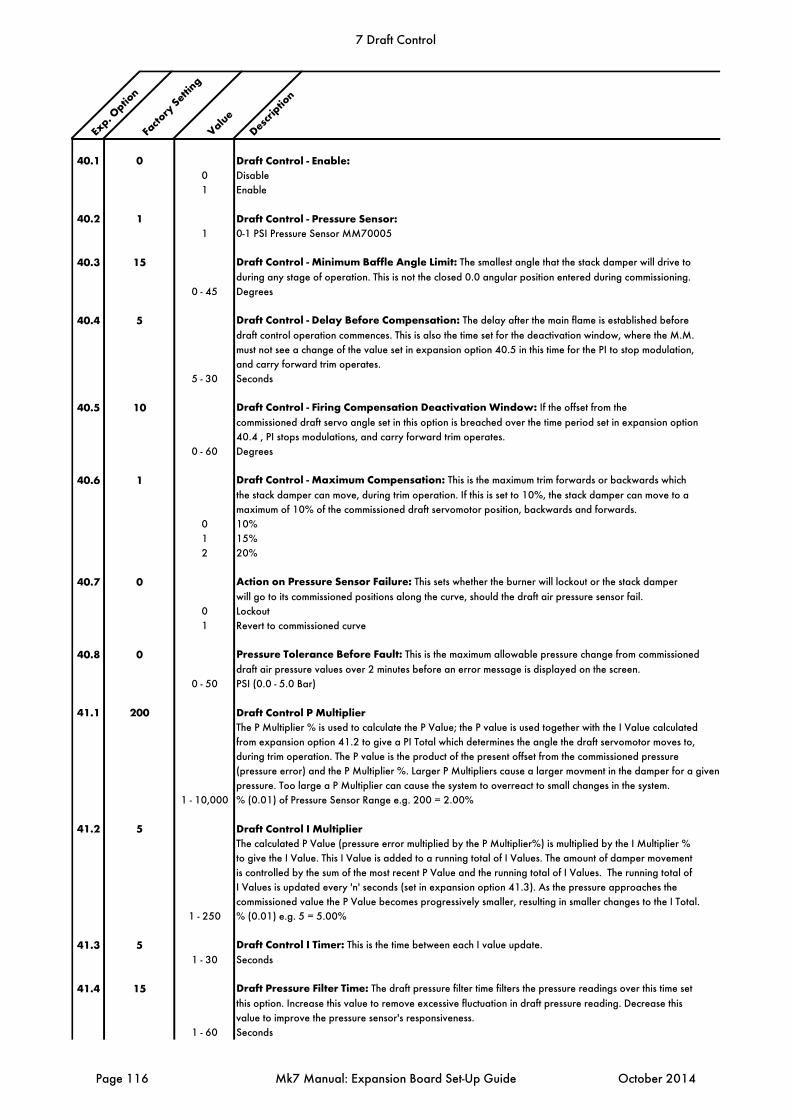
Exp. O
ption
Facto
ry Setti
ng
ValueDescr
iption
40.1 0 Draft Control - Enable:0 Disable
1 Enable
40.2 1 Draft Control - Pressure Sensor:1 0-1 PSI Pressure Sensor MM70005
40.3 15 Draft Control - Minimum Baffle Angle Limit: The smallest angle that the stack damper will drive to
during any stage of operation. This is not the closed 0.0 angular position entered during commissioning.
0 - 45 Degrees
40.4 5 Draft Control - Delay Before Compensation: The delay after the main flame is established before
draft control operation commences. This is also the time set for the deactivation window, where the M.M.
must not see a change of the value set in expansion option 40.5 in this time for the PI to stop modulation,
and carry forward trim operates.
5 - 30 Seconds
40.5 10 Draft Control - Firing Compensation Deactivation Window: If the offset from the
commissioned draft servo angle set in this option is breached over the time period set in expansion option
40.4 , PI stops modulations, and carry forward trim operates.
0 - 60 Degrees
40.6 1 Draft Control - Maximum Compensation: This is the maximum trim forwards or backwards which
the stack damper can move, during trim operation. If this is set to 10%, the stack damper can move to a
maximum of 10% of the commissioned draft servomotor position, backwards and forwards.
0 10%
1 15%
2 20%
40.7 0 Action on Pressure Sensor Failure: This sets whether the burner will lockout or the stack damper
will go to its commissioned positions along the curve, should the draft air pressure sensor fail.
0 Lockout
1 Revert to commissioned curve
40.8 0 Pressure Tolerance Before Fault: This is the maximum allowable pressure change from commissioned
draft air pressure values over 2 minutes before an error message is displayed on the screen.
0 - 50 PSI (0.0 - 5.0 Bar)
41.1 200 Draft Control P MultiplierThe P Multiplier % is used to calculate the P Value; the P value is used together with the I Value calculated
from expansion option 41.2 to give a PI Total which determines the angle the draft servomotor moves to,
during trim operation. The P value is the product of the present offset from the commissioned pressure
(pressure error) and the P Multiplier %. Larger P Multipliers cause a larger movment in the damper for a given
pressure. Too large a P Multiplier can cause the system to overreact to small changes in the system.
1 - 10,000 % (0.01) of Pressure Sensor Range e.g. 200 = 2.00%
41.2 5 Draft Control I MultiplierThe calculated P Value (pressure error multiplied by the P Multiplier%) is multiplied by the I Multiplier %
to give the I Value. This I Value is added to a running total of I Values. The amount of damper movement
is controlled by the sum of the most recent P Value and the running total of I Values. The running total of
I Values is updated every 'n' seconds (set in expansion option 41.3). As the pressure approaches the
commissioned value the P Value becomes progressively smaller, resulting in smaller changes to the I Total.
1 - 250 % (0.01) e.g. 5 = 5.00%
41.3 5 Draft Control I Timer: This is the time between each I value update.
1 - 30 Seconds
41.4 15 Draft Pressure Filter Time: The draft pressure filter time filters the pressure readings over this time set
this option. Increase this value to remove excessive fluctuation in draft pressure reading. Decrease this
value to improve the pressure sensor's responsiveness.
1 - 60 Seconds
7 Draft Control
Page 116 Mk7 Manual: Expansion Board Set-Up Guide October 2014
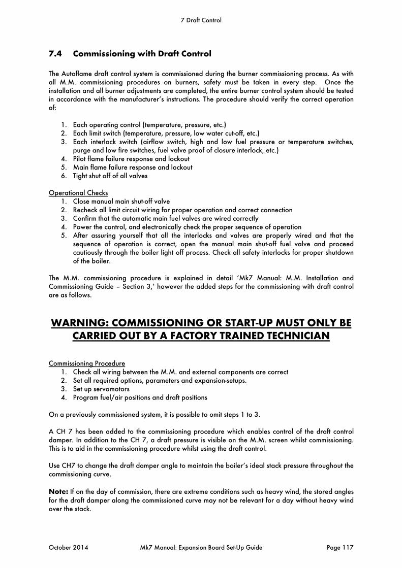
7.4 Commissioning with Draft Control
The Autoflame draft control system is commissioned during the burner commissioning process. As with all M.M. commissioning procedures on burners, safety must be taken in every step. Once the installation and all burner adjustments are completed, the entire burner control system should be tested in accordance with the manufacturer’s instructions. The procedure should verify the correct operation of:
1. Each operating control (temperature, pressure, etc.) 2. Each limit switch (temperature, pressure, low water cut-off, etc.) 3. Each interlock switch (airflow switch, high and low fuel pressure or temperature switches,
purge and low fire switches, fuel valve proof of closure interlock, etc.) 4. Pilot flame failure response and lockout 5. Main flame failure response and lockout 6. Tight shut off of all valves
Operational Checks
1. Close manual main shut-off valve 2. Recheck all limit circuit wiring for proper operation and correct connection 3. Confirm that the automatic main fuel valves are wired correctly 4. Power the control, and electronically check the proper sequence of operation 5. After assuring yourself that all the interlocks and valves are properly wired and that the
sequence of operation is correct, open the manual main shut-off fuel valve and proceed cautiously through the boiler light off process. Check all safety interlocks for proper shutdown of the boiler.
The M.M. commissioning procedure is explained in detail ‘Mk7 Manual: M.M. Installation and Commissioning Guide – Section 3,’ however the added steps for the commissioning with draft control are as follows.
WARNING: COMMISSIONING OR START-UP MUST ONLY BE CARRIED OUT BY A FACTORY TRAINED TECHNICIAN
Commissioning Procedure
1. Check all wiring between the M.M. and external components are correct 2. Set all required options, parameters and expansion-setups. 3. Set up servomotors 4. Program fuel/air positions and draft positions
On a previously commissioned system, it is possible to omit steps 1 to 3. A CH 7 has been added to the commissioning procedure which enables control of the draft control damper. In addition to the CH 7, a draft pressure is visible on the M.M. screen whilst commissioning. This is to aid in the commissioning procedure whilst using the draft control. Use CH7 to change the draft damper angle to maintain the boiler’s ideal stack pressure throughout the commissioning curve. Note: If on the day of commission, there are extreme conditions such as heavy wind, the stored angles for the draft damper along the commissioned curve may not be relevant for a day without heavy wind over the stack.
7 Draft Control
October 2014 Mk7 Manual: Expansion Board Set-Up Guide Page 117
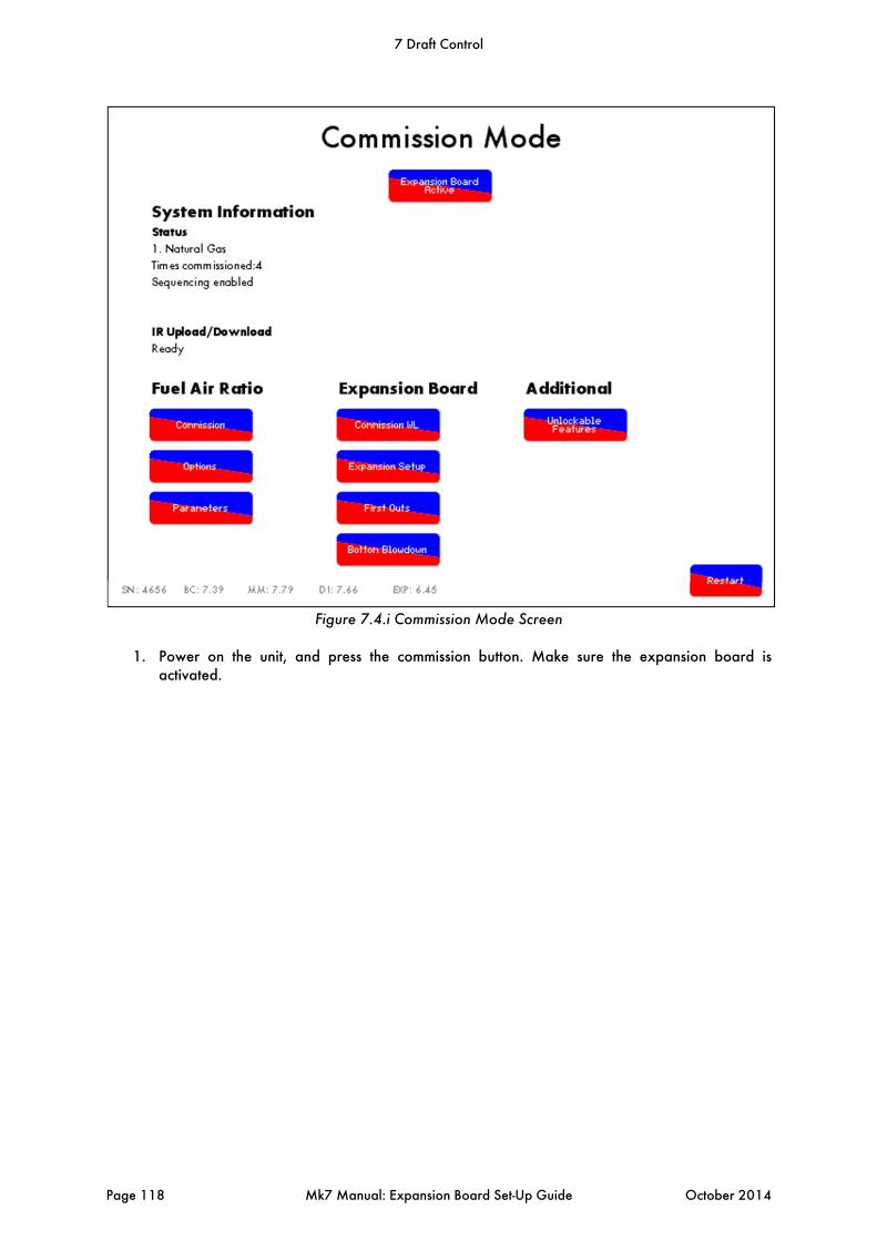
Figure 7.4.i Commission Mode Screen
1. Power on the unit, and press the commission button. Make sure the expansion board is
activated.
7 Draft Control
Page 118 Mk7 Manual: Expansion Board Set-Up Guide October 2014

Figure 7.4.ii Draft Control Expansion Options
2. Configure expansion options 40.1 to 41.4 for the draft control operation. It is recommended
that P and I options are set to default. If changes to either the P or the I are required, it is suggested that small changes are done to each at a time, to avoid less than satisfactory or excessive trim on the stack damper.
7 Draft Control
October 2014 Mk7 Manual: Expansion Board Set-Up Guide Page 119

Figure 7.4.iii Close Position
3. Enter commissioning mode.
4. Enter the CLOSED position (please note that the draft control minimum angle is set by
expansion set-up 40.3). The draft control damper can be increased/ decreased using CH 7 up
and down arrows .
Note: Once a CLOSE position is entered the draft servomotor will drive to the minimum baffle angle limit, expansion option 40.3.
7 Draft Control
Page 120 Mk7 Manual: Expansion Board Set-Up Guide October 2014
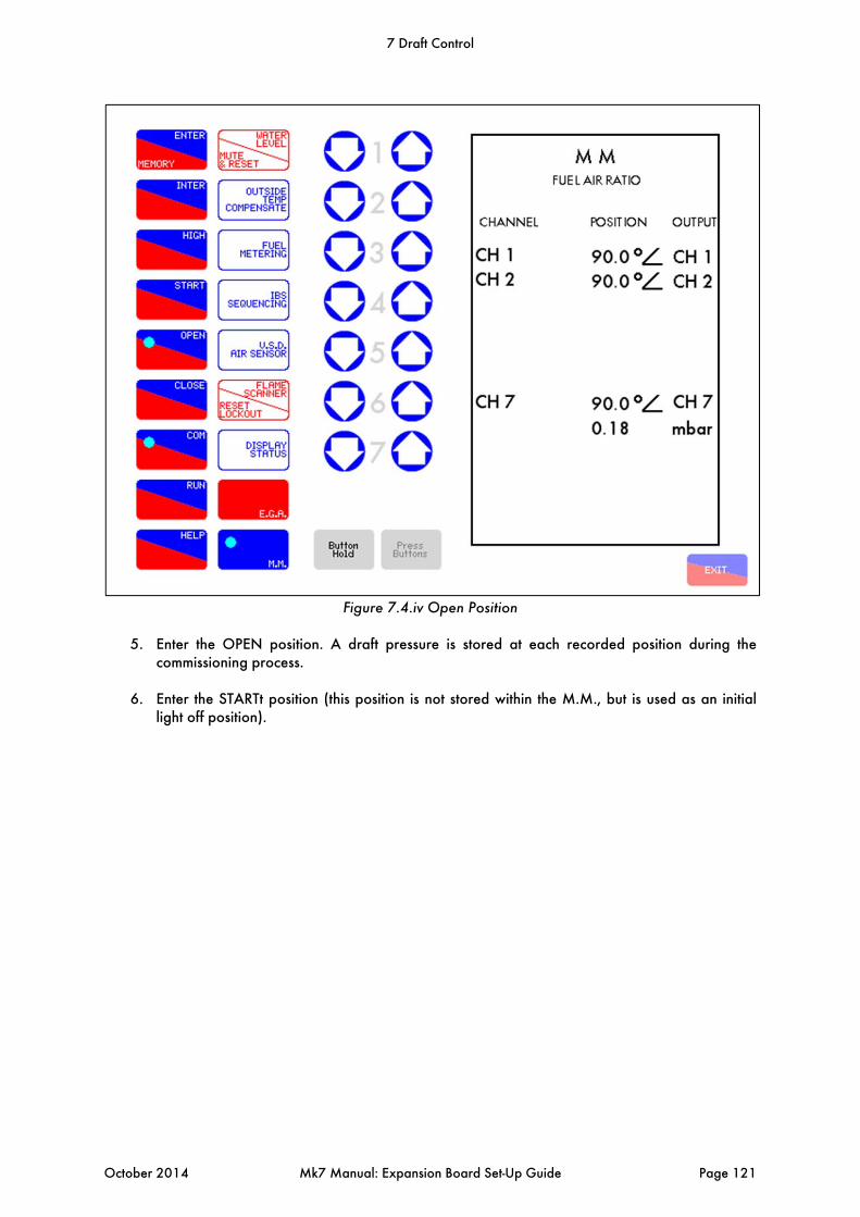
Figure 7.4.iv Open Position
5. Enter the OPEN position. A draft pressure is stored at each recorded position during the
commissioning process.
6. Enter the STARTt position (this position is not stored within the M.M., but is used as an initial light off position).
7 Draft Control
October 2014 Mk7 Manual: Expansion Board Set-Up Guide Page 121
Figure 7.4.v High Position
7. Drive the servomotors up to HIGH FIRE position and then press Enter.
7 Draft Control
Page 122 Mk7 Manual: Expansion Board Set-Up Guide October 2014

Figure 7.4.vi Inter Position
8. Enter up to 15 inter positions to make up the firing curve (minimum 3 inter positions).
Note: It is not possible to drive the draft servomotor past the minimum baffle angle limit, expansion option 40.3
7 Draft Control
October 2014 Mk7 Manual: Expansion Board Set-Up Guide Page 123

Figure 7.4.vii Start Position
9. Once all the required inter points have been entered, choose a low fire START position, press
Enter and then press Run to save the combustion curve. Note: It will not be possible to adjust CH 7 below its minimum angle as set in expansion option 40.3. if the angle is too high, either enter the position and adjust in a single point change once the option has been changed or change the expansion option and start commissioning from the beginning.
7 Draft Control
Page 124 Mk7 Manual: Expansion Board Set-Up Guide October 2014
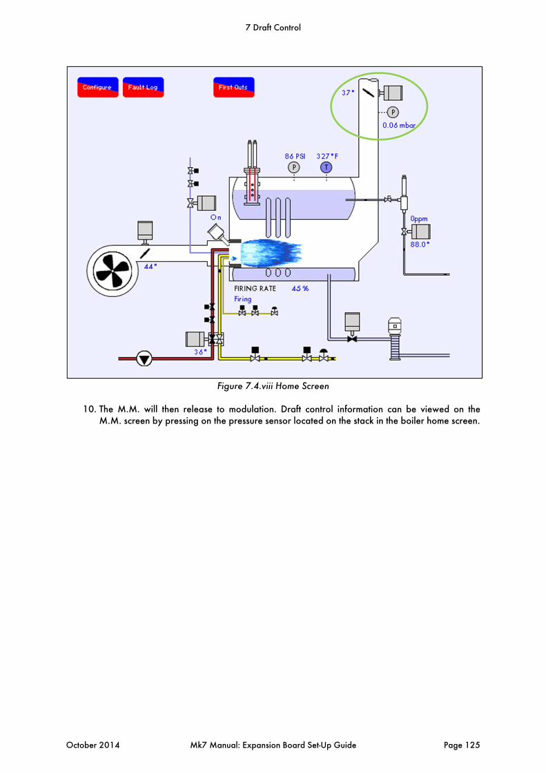
Figure 7.4.viii Home Screen
10. The M.M. will then release to modulation. Draft control information can be viewed on the
M.M. screen by pressing on the pressure sensor located on the stack in the boiler home screen.
7 Draft Control
October 2014 Mk7 Manual: Expansion Board Set-Up Guide Page 125

Figure 7.4.ix Draft Control Pressure Curve
11. In the draft control screens, you are able to view instantaneous data in comparison to the
commissioned data. The draft control pressure curve displays the current draft pressure in comparison to the commissioned value in relation to the current fuel valve position. In addition the pressure trend for the whole firing rate is visible.
7 Draft Control
Page 126 Mk7 Manual: Expansion Board Set-Up Guide October 2014
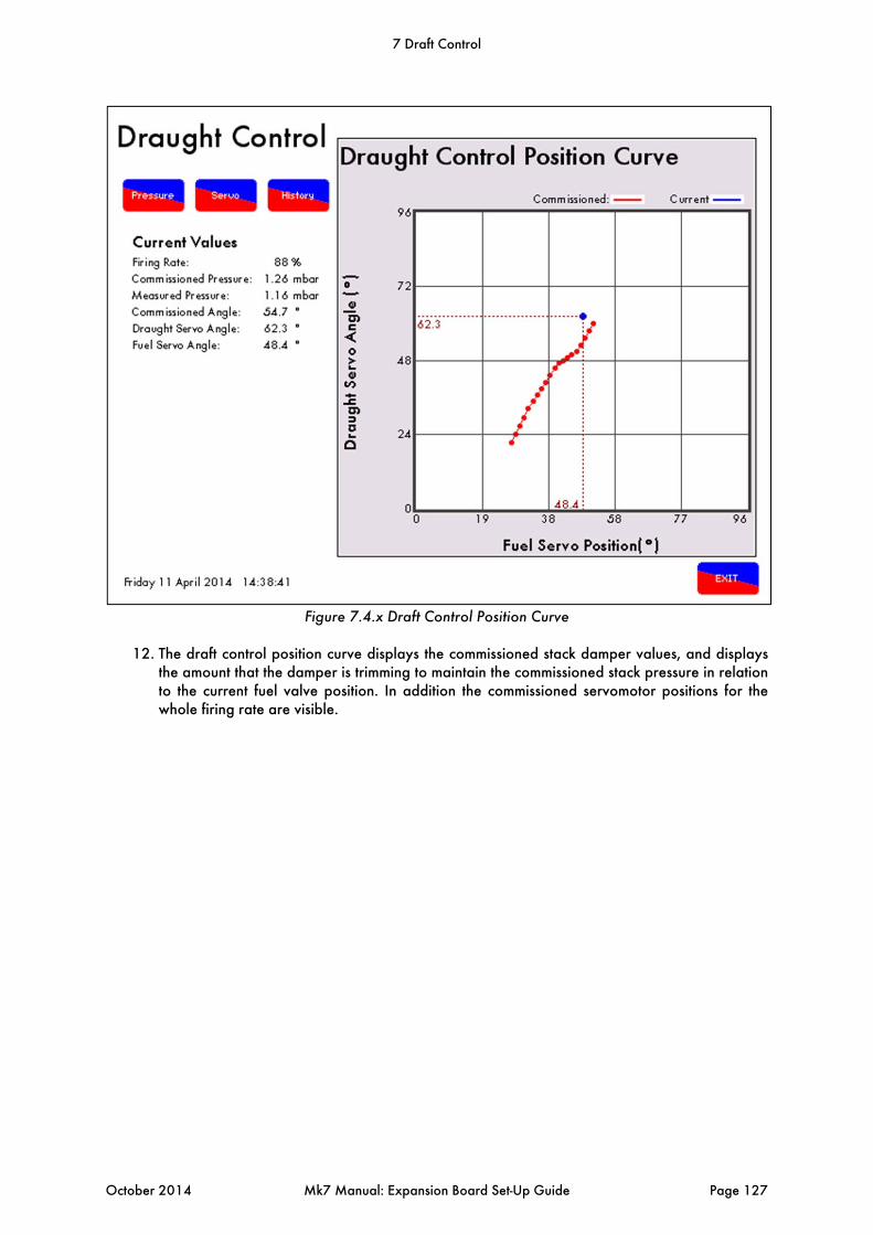
Figure 7.4.x Draft Control Position Curve
12. The draft control position curve displays the commissioned stack damper values, and displays
the amount that the damper is trimming to maintain the commissioned stack pressure in relation to the current fuel valve position. In addition the commissioned servomotor positions for the whole firing rate are visible.
7 Draft Control
October 2014 Mk7 Manual: Expansion Board Set-Up Guide Page 127
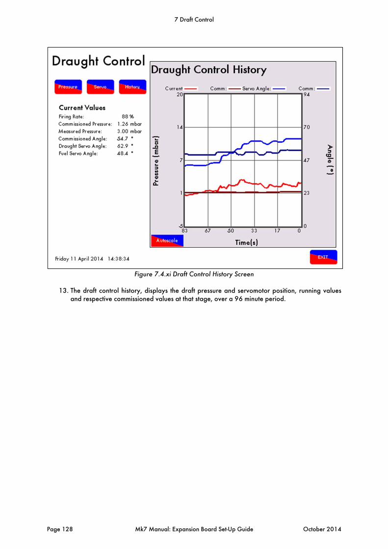
Figure 7.4.xi Draft Control History Screen
13. The draft control history, displays the draft pressure and servomotor position, running values
and respective commissioned values at that stage, over a 96 minute period.
7 Draft Control
Page 128 Mk7 Manual: Expansion Board Set-Up Guide October 2014
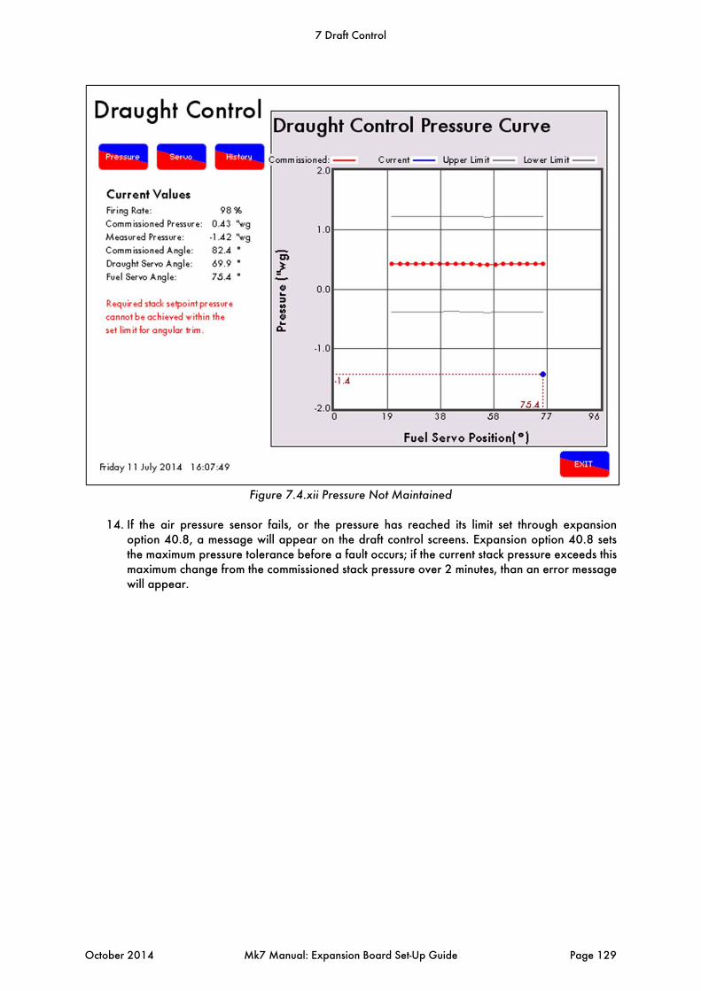
Figure 7.4.xii Pressure Not Maintained
14. If the air pressure sensor fails, or the pressure has reached its limit set through expansion option 40.8, a message will appear on the draft control screens. Expansion option 40.8 sets the maximum pressure tolerance before a fault occurs; if the current stack pressure exceeds this maximum change from the commissioned stack pressure over 2 minutes, than an error message will appear.
7 Draft Control
October 2014 Mk7 Manual: Expansion Board Set-Up Guide Page 129
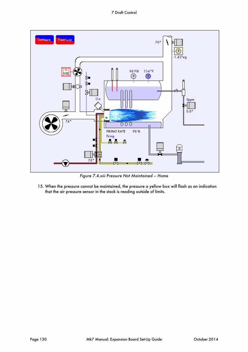
Figure 7.4.xiii Pressure Not Maintained – Home
15. When the pressure cannot be maintained, the pressure a yellow box will flash as an indication
that the air pressure sensor in the stack is reading outside of limits.
7 Draft Control
Page 130 Mk7 Manual: Expansion Board Set-Up Guide October 2014
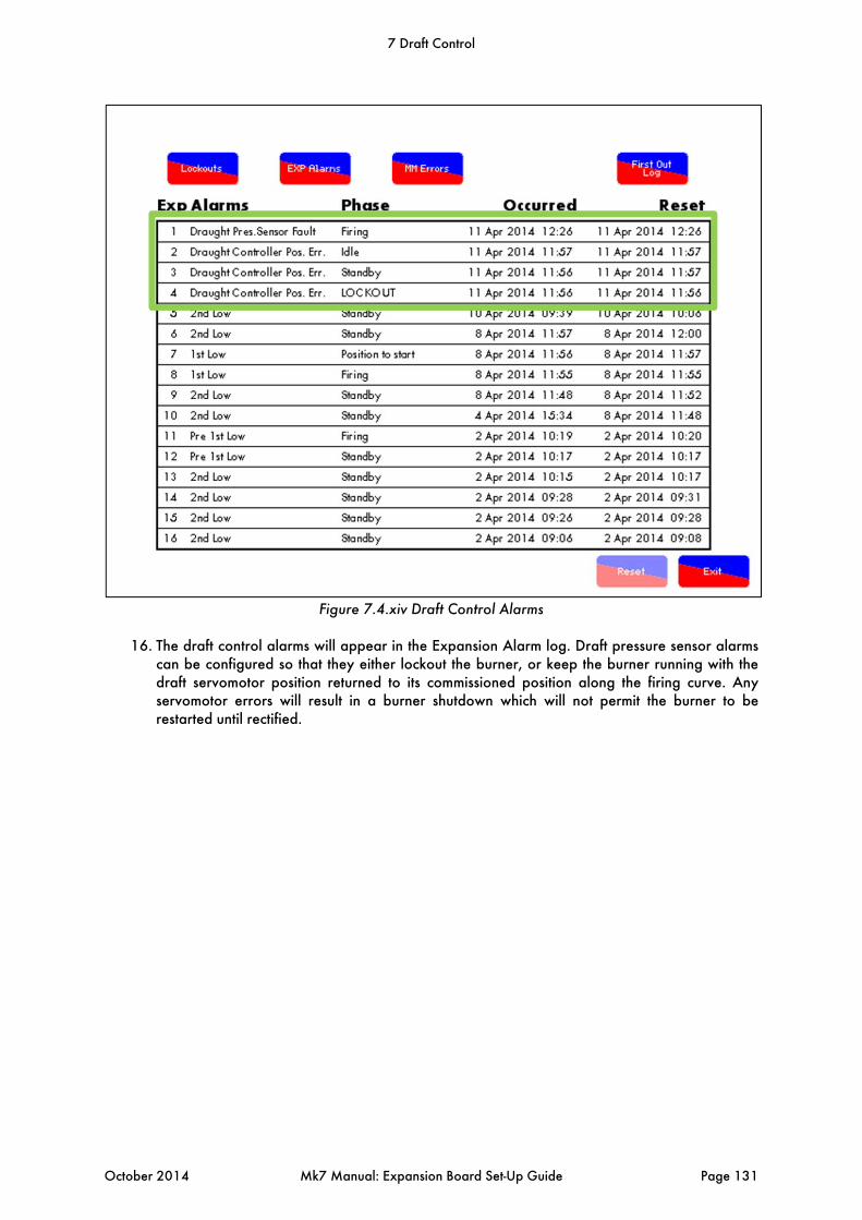
Figure 7.4.xiv Draft Control Alarms
16. The draft control alarms will appear in the Expansion Alarm log. Draft pressure sensor alarms
can be configured so that they either lockout the burner, or keep the burner running with the draft servomotor position returned to its commissioned position along the firing curve. Any servomotor errors will result in a burner shutdown which will not permit the burner to be restarted until rectified.
7 Draft Control
October 2014 Mk7 Manual: Expansion Board Set-Up Guide Page 131

7.5 Draft Control Operation
The draft control trim functionality follows the same ideology to the E.G.A., where corrections are made to air damper to compensate for the changes in exhaust gas values from their commissioned values, caused by fluctuations in ambient conditions. For Autoflame draft control, corrections are made to the stack damper to compensate for changes in wind and ambient conditions which cause the stack pressure to differ from the commissioned stack pressure along the fuel curve. Once the burner starts up and the main flame stabilised, there is a time delay where no draft control operation occurs, set in expansion option 40.4. After this time delay elapses, as the air going into the burner is increased from low fire to high fire, the boiler pressure may change and the draft servomotor will move to follow these changes as commissioned. If the atmospheric or stack pressures have changed from their commissioned values along the curve, the air damper will either move in the open, or close direction to adjust the air pressure in the stack back to its set value. The smallest angle that the draft damper can drive to while running is defined by expansion option 40.3; when the burner turns off, the draft damper will go to commissioned closed position to maintain heat within the boiler. If draft control is optioned off after being commissioned, then the draft servomotor will drive to the open position and re-commissioning is not required. The draft servomotor must remain connected and is still in operation so any channel errors will still shutdown the burner and generate an on screen indication. A full re-commission with this turned off will be required to remove the servomotor from the system. The air pressure sensor has no effect once draft control is optioned off and can be disconnected without any lockouts occurring. 7.5.1 Deactivation Window
There is a deactivation window, outside of which no trim occurs, and the air damper remains at the previously trimmed position until back within the window and trim is required. This deactivation window is defined by expansion options 40.4 - delay before compensation and 40.5 - firing compensation deactivation window. If the draft servomotor has moved more than the set angular degrees “x”, within the time period set “y”, than no trim functionality will operate, if trim has been performed prior to this deactivation then the trim is carried forward. For example, when the burner is first switched on with a high demand, or if the burner comes out of warming in lead-lag control, or is switched from low flame hold to auto mode. In these situations the firing rate may ramp up quickly to meet load demand, at this point if the draft servomotor is required to move greater than the set amount (40.5) quicker than the set time (40.3) then no trim functionality will occur and any trim % will be carried forward. See figure 7.5.1.i for a graphical representation of draft activation window.
7 Draft Control
Page 132 Mk7 Manual: Expansion Board Set-Up Guide October 2014
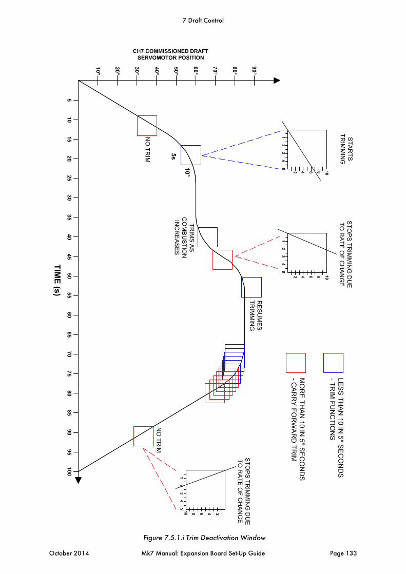
Figure 7.5.1.i Trim Deactivation Window
7 Draft Control
October 2014 Mk7 Manual: Expansion Board Set-Up Guide Page 133
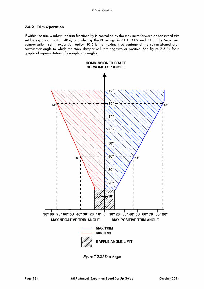
7.5.2 Trim Operation
If within the trim window, the trim functionality is controlled by the maximum forward or backward trim set by expansion option 40.6, and also by the PI settings in 41.1, 41.2 and 41.3. The ‘maximum compensation’ set in expansion option 40.6 is the maximum percentage of the commissioned draft servomotor angle to which the stack damper will trim negative or positive. See figure 7.5.2.i for a graphical representation of example trim angles.
Figure 7.5.2.i Trim Angle
7 Draft Control
Page 134 Mk7 Manual: Expansion Board Set-Up Guide October 2014

8 TROUBLESHOOTING AND DIAGNOSTICS
8.1 Expansion Alarms
The M.M. will display up to 16 expansion alarms. Please find to the expansion alarms bellow: 1 2nd Low Level The water level has fallen below the commissioned 2nd Low
position. If the alarm was preceded by a 1st Low alarm, the 1st Low entry will be automatically replaced within the alarm log.
2 Probe 1 Comms Fault The communications between the water level control and probe 1 have failed, exceeding the maximum allowed period of 3 seconds. Check probe wiring/ failed probe.
3 Probe 2 Comms Fault The communications between the water level control and probe 2 have failed, exceeding the maximum allowed period of 3 seconds. Check probe wiring/ failed probe.
4 Probe 1 Short Probe 1 has short circuit failure. This probe’s water level is currently outside of the normal operating limits range. This may be caused by a probe hardware failure. Contact an Autoflame technology centre.
5 Probe 2 Short Probe 2 has short circuit failure. This probe’s water level is currently outside of the normal operating limits range. This may be caused by a probe hardware failure. Contact an Autoflame technology centre.
6 Probe Mismatch The probe levels are not currently in line with commissioned levels suggesting a probe failure or alteration. This can also be caused by overheating of the electronics. It is important to lag the flanges if the probes are mounted directly into the boiler shell. Try cleaning and re-commissioning the probes.
7 Probe 1 TC Probe 1 has a temperature compensation failure. This probe’s water level is currently outside of normal operating conditions when compensating the water level. Check the wiring, clean the probes, and re-commissioning the probes. This could be probe hardware failure.
8 Probe 2 TC Probe 2 has a temperature compensation failure. This probe’s water level is currently outside of normal operating conditions when compensating the water level. Check the wiring, clean the probes, and re-commissioning the probes. This could be probe hardware failure.
9 Permanent Reset The water level control or M.M. mute/reset button was pressed for longer than 10 seconds. To reset this alarm ensure that both buttons are not pressed for at least 10 seconds. This will become a keystuck-reset alarm.
10 Permanent Test The water level control test input button was pressed for longer than 60 seconds.
8 Troubleshooting and Diagnostics
October 2014 Mk7 Manual: Expansion Board Set-Up Guide Page 135

11 Perm Reset Cleared This is now a keystuck-reset alarm.
12 EEprom PU Corrupt On power up, the EEprom test has failed; the water level control has not been used before, has a faulty EEprom. If the problem persists after resetting the error, contact Autoflame.
13 Bogus PU State The EEProm is in a bogus state, if the problem persists after resetting the error, contact Autoflame.
14 Control Cfg Mismatch The configuration and commission data do not have matching control type options. This would occur if the configuration has been changed after commissioning.
15 Probe 1 Com Data Probe 1 has corrupt commissioning data. Restart and re-commission the probes if error persists after resetting error.
16 Probe 2 Com Data Probe 2 has corrupt commissioning data. Restart and re-commission the probes if error persists after resetting error.
17 Config Range Check One or more of the configuration options is outside of the allowed range.
18 1st Low Level The water level is currently below the commissioned 1st Low position. If the alarm precedes a 2nd Low alarm, it will be automatically replaced by a 2nd Low alarm in the log. Once the water returns to a level above the commissioned 1st Low, the error will remain within the log but it will be automatically reset.
19 High Water Level The water level is currently above the commissioned High Water position. This alarm will clear automatically when the water level is reduced below the commissioned High Water position.
20 Probe 1 Still Water The signal from probe 1 appears static indicating that the probe is not in the water.
21 Probe 2 Still Water The signal from probe 2 appears static indicating that the probe is not in the water.
22 Probes Diverse One probe is reading above high water, the other is below 1st Low water. Usually caused by auxiliary inputs incorrectly connected/ optioned. See expansion option 12.1
23 Pre 1st Low The water level is below the commissioned Pre 1st Low position.
24 Pre High Water The water level is above the commissioned Pre High Water position.
25 Btm Blowdn Software Fault
Bottom blowdown software fault. Please contact Autoflame.
26 Btm Blowdn Comms Fault
Bottom blowdown board has a comms failure.
27 Btm Blowdn 24V Fault Bottom blowdown board – main power failed
8 Troubleshooting and Diagnostics
Page 136 Mk7 Manual: Expansion Board Set-Up Guide October 2014

28 Btm Blowdn Battery Fault
Bottom blowdown board – battery power failed
29 Btm Blowdn Opening Fault
Bottom blowdown valve failed to move while opening
30 Btm Blowdn Closing Fault
Bottom blowdown valve failed to move while closing
31 2nd Low Probe – No Water
The 2nd Low probe detects no water.
32 2nd Low Probe System Error
Please contact Autoflame.
33 2nd Low Probe Comms Fault
The 2nd Low probe has a communications failure, check wiring.
34 TDS Probe Comms Error
The TDS probe has a communications failure, check wiring.
35 TDS Limit Breached The TDS limit has been breached, check configuration options and water conditions.
36 TDS Valve Position Error
The TDS valve has a positioning error, check wiring.
37 Feed water Valve Position Error
The feed water valve has a positioning error, check wiring.
38 Draft Controller Position Error
The draft control servomotor has a positioning error, check wiring and feedback.
39 Sensor T1 Fault The temperature sensor wired in terminal #T1 has a fault.
40 Sensor T1A Fault The temperature sensor wired in terminal #T1A has a fault.
41 Sensor T2 Fault The temperature sensor wired in terminal #T2 has a fault.
42 Flow meter fault The steam flow meter has a fault.
43 Draft Pressure Sensor Fault
The draft control pressure sensor has a fault, check wiring.
44 Draft Pressure Tolerance Fail
The draft control pressure tolerance is outside the configured tolerance band for longer than 2 minutes.
45 Bottom BD Not Commissioned
The bottom blowdown operation has not been commissioned.
254 WL Board Reset Please contact Autoflame.
8 Troubleshooting and Diagnostics
October 2014 Mk7 Manual: Expansion Board Set-Up Guide Page 137


Notes


Autoflame Engineering Ltd Unit1-2 Concorde Business Centre
Airport Industrial Estate, Wireless Road Biggin Hill, Kent TN16 3YN
United Kingdom +44 (0) 845 872 2000 www.autoflame.com
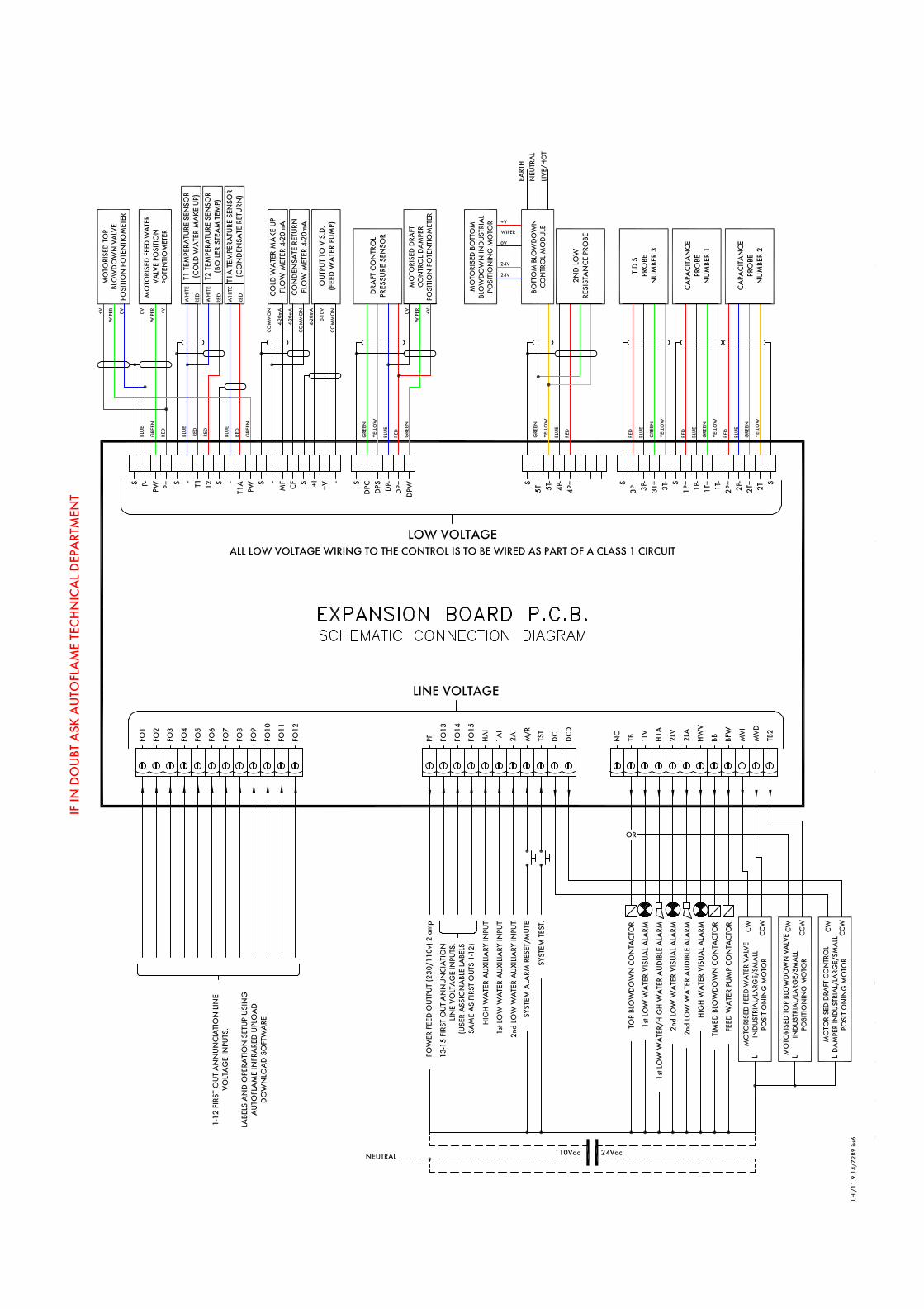


![DEAERATOR - powerhx.com · DEAERATOR General [ Typical Deaerator Connections and Accessories ] Principle of deaerating Classification by Shape The removal of dissolved gases from](https://static.fdocuments.in/doc/165x107/5e0656589a5fbe7d5a551d58/deaerator-deaerator-general-typical-deaerator-connections-and-accessories-.jpg)