Mixed Stepping / Scanning Mode Control of Stick-Slip SEM ...
16
HAL Id: hal-03225760 https://hal.archives-ouvertes.fr/hal-03225760 Submitted on 13 May 2021 HAL is a multi-disciplinary open access archive for the deposit and dissemination of sci- entific research documents, whether they are pub- lished or not. The documents may come from teaching and research institutions in France or abroad, or from public or private research centers. L’archive ouverte pluridisciplinaire HAL, est destinée au dépôt et à la diffusion de documents scientifiques de niveau recherche, publiés ou non, émanant des établissements d’enseignement et de recherche français ou étrangers, des laboratoires publics ou privés. Mixed Stepping / Scanning Mode Control of Stick-Slip SEM-integrated Nano-robotic Systems Raouia Oubellil, Alina Voda, Mokrane Boudaoud, Stéphane Régnier To cite this version: Raouia Oubellil, Alina Voda, Mokrane Boudaoud, Stéphane Régnier. Mixed Stepping / Scanning Mode Control of Stick-Slip SEM-integrated Nano-robotic Systems. Sensors and Actuators A: Physical , Elsevier, 2019, 285, pp.258-268. 10.1016/j.sna.2018.08.042. hal-03225760
Transcript of Mixed Stepping / Scanning Mode Control of Stick-Slip SEM ...

HAL Id: hal-03225760https://hal.archives-ouvertes.fr/hal-03225760
Submitted on 13 May 2021
HAL is a multi-disciplinary open accessarchive for the deposit and dissemination of sci-entific research documents, whether they are pub-lished or not. The documents may come fromteaching and research institutions in France orabroad, or from public or private research centers.
L’archive ouverte pluridisciplinaire HAL, estdestinée au dépôt et à la diffusion de documentsscientifiques de niveau recherche, publiés ou non,émanant des établissements d’enseignement et derecherche français ou étrangers, des laboratoirespublics ou privés.
Mixed Stepping / Scanning Mode Control of Stick-SlipSEM-integrated Nano-robotic Systems
Raouia Oubellil, Alina Voda, Mokrane Boudaoud, Stéphane Régnier
To cite this version:Raouia Oubellil, Alina Voda, Mokrane Boudaoud, Stéphane Régnier. Mixed Stepping / ScanningMode Control of Stick-Slip SEM-integrated Nano-robotic Systems. Sensors and Actuators A: Physical, Elsevier, 2019, 285, pp.258-268. �10.1016/j.sna.2018.08.042�. �hal-03225760�

Page 1 of 15
Accep
ted
Man
uscr
ipt
Mixed Stepping / Scanning Mode Control of Stick-Slip SEM-integrated Nano-roboticSystems
R. Oubellil1,∗, A. Voda1, M. Boudaoud2 and S. Regnier2
1GIPSA-lab, Control Systems department, ENSE3 bat B, BP 46, Domaine Universitaire,38400 Saint Martin d’Heres, France
2Sorbonne Universite, Institut des Systemes Intelligents et de Robotique, UMR 7222, ISIR, F-75005 Paris, France
Abstract
The ability to do dexterous automated and semi-automated tasks at the micro- and nano-meter scales inside a Scanning ElectronMicroscope (SEM) is a critical issue for nanotechnologies. SEM-integrated nano-robotic systems with several Degrees Of Freedom(DOF) and one or several end-effectors have therefore widely emerged in research laboratories and industry. The Piezoelectric Stick-Slip (PSS) is one of the best actuation principle for SEM-integrated nano-robotic systems as it has two operating modes, namely acoarse positioning mode with long travel range, and a fine positioning mode with a resolution of the order of the nanometer. Themain contribution of this paper is the design of a switch control strategy to deal efficiently and in a transparent way from the user’spoint of view, with the transition between the coarse and the fine operating modes of PSS actuators. The aim is to be able to performpositioning tasks with a millimeter displacement range and a nanometer resolution without worrying about the mode of operationof the actuator. The coarse mode and the fine mode are respectively controlled with a frequency/voltage proportional control anda H∞ control. The switch control is based on an internal model of the actuator. Experimental results show the effectiveness of thenew mixed coarse/fine mode control strategy to satisfy closed-loop stability and bumpless specifications at the switching time. Forthe best knowledge of the authors, this result is the first demonstration of such a control capability for PSS actuators.
1. Introduction
SEM-integrated nano-robotic systems have widely emergedin recent years to address the issue of automated and semi-automated tasks for nanotechnologies. The SEM is particularlyinteresting because it provides a visual feedback with nanome-ter resolution and a depth of field better than that of light mi-croscopes. Nano-robotics inside the SEM enables in-situ tasksat the nanometer scale such as nano-manipulation [1, 2], nano-assembly [3, 4] as well as electrical [5] and mechanical charac-terization [6] of materials and biological samples at the smallscales. SEM integrated nano-robotic systems have to be ableto generate two motion modes, namely a coarse positioningwith a displacement range of several micrometers or millime-ters to bring an end effector close to the micro/nano-object tobe manipulated, and a fine positioning with a resolution in thenanometer range to locally characterize and/or manipulate theobject. According to the literature, such robots are generallyactuated by piezoelectric inertial actuators in the coarse and thefine modes independently [3, 7, 5, 4, 1]. Particularly, the ba-sic architecture of Piezoelectric Stick-Slip (PSS) type actuator[3, 7, 5] is composed of a Piezoelectric Element (PE), a slider,and a friction material between the PE and the slider. It operatesin scanning mode when there is no slip between the PE and the
✩This work was not supported by any organization.∗Corresponding authorEmail address: [email protected] (R. Oubellil)
slider, and in stepping mode when several sequences of stickand slip phases occur. In scanning mode, the PSS actuator canperform a fine positioning with a nanometer resolution but thedisplacement range is limited by the maximal deformation ofthe PE (∼ few micrometers). In stepping mode, a coarse posi-tioning with a millimeter displacement range can be achieved,but with a poor resolution. In this mode, the input voltage isusually a sawtooth signal.
The state of art has shown that PSS actuators have a realpotential for nano-robotics. Design issues have been deeply in-vestigated [8]. However, several control issues related to thenonlinear behavior and the hybrid operating mode of these ac-tuators still require studies in order to satisfy the demandingperformance in nanotechnologies. Existing control strategiescan be classified into control in scanning mode and control instepping mode. The objective of the control in scanning modeis to reduce the hysteresis effect and to damp the vibrations [9].Hysteresis may induce open-loop positioning errors as high as10%-15% of the displacement range [10]. Furthermore, signif-icant oscillations of a hundred nanometers at the fundamentalresonance frequency can be observed in the slider displacement[11]. These mechanical vibrations present a major problem innano-robotics. For instance, for in situ stiffness measurementson membranes of 200 nm thickness [12], an oscillation of 100nm of the end-effector can produce the membrane destruction.Open-loop strategies can be used for hysteresis compensation[13, 14] [15, 16, 17] and vibration damping [18, 19]. However,
Preprint submitted to Sensors and Actuators September 28, 2018

Page 2 of 15
Accep
ted
Man
uscr
ipt
in practice, it is difficult to obtain precise compensators, andhence to guarantee positioning accuracy. Also, these methodsare not robust against hysteresis variations and shifts in the reso-nance frequency. For these reasons, numerous closed-loop con-trol strategies have been studied in the literature, including pole-placement [20], PID control [21], H∞ control [22, 23] [24], slid-ing mode control [25], LQG control [26], and so on. On theother hand, few techniques exist in the literature to control PSSactuators in stepping modes. A frequency proportional con-troller is proposed in [27] where the frequency of the sawtoothcontrol voltage is chosen based on the tracking error. A cascadecontroller is designed via dehybridization in [28] using a hybridmodel of the actuator. In the inner-loop, a hybrid controller isdesigned to impose a time-scale separation between continuousand discrete states. In the outer-loop, a continuous proportionalderivative controller is developed using an approximated con-tinuous model of the inner-loop in order to satisfy closed-loopstability. A frequency/amplitude proportional controller is pre-sented in [29] to control the amplitude and the frequency ofthe sawtooth control signal separately. The proportional gainsare determined in the same way as for classical proportionalcontrollers. None of the existing controllers has dealt with thestepping/scanning switch problem of PSS actuators. In fact,this switch generally leads to closed-loop instability and signif-icant vibrations at switching time, which compromises the useof these actuators for fully-automated tasks inside a SEM.
This paper focuses on a new control strategy able to drivea PSS actuator in closed loop in both stepping and scanningmodes while guaranteeing an efficient bumpless switch betweenthese two operating modes. The experimental setup used to val-idate the proposed strategy is a nano-robotic platform made upof a Cartesian structure actuated by PSS actuators (Fig. 1). Inour approach, these actuators are initially controlled separatelyin scanning mode and in stepping mode. The hybrid controllerinvolves a H∞ scanning mode controller, a frequency/ ampli-tude ( f /u) proportional stepping mode controller, and a switch-ing strategy using an internal model of the actuator. Experimen-tal results demonstrate the effectiveness of the new hybrid con-troller and its ability to achieve millimeter range motion witha resolution of the order of the nanometer. The closed-loopsystem enables automated coarse/fine positioning which opensnew perspectives on the use of PSS actuators in nano-robotics,particularly to perform precise automated tasks inside a SEM.
The paper is structured as follows. In Section 2, the exper-imental setup used in this study is described. Sections 3 and4 deal respectively with the scanning control and the steppingcontrol strategies. In section 5, the new mixed stepping/scanningmode controller is presented. Section 6 concludes the paper.
2. Experimental setup
The experimental setup of the laboratory enables SEM ma-nipulation and characterization tasks [12]. It consists of a SEM,a multi-Degrees Of Freedom (DOF) nano-robotic system in-cluding the 3 axes serial nanorobot that is studied in this paper
Z axis
X axis
Y axis
x
y
z
Figure 1: The 3-DOF Cartesian nano-robotic structure. It is composed of threeaxes X, Y and Z. Each axis is actuated by a piezoelectric stick slip actuator(SmarAct SLC-1720-S-HV).
(Fig. 1), a processor board and a human-robot interface. Theprocessor board features a QorlQ P5020 dual-core processorrunning at 2 GHz. The serial nano-robotic system is actuated byPSS actuators of the same reference (SLC-1720-S-HV). Eachactuator integrates an optical encoder sensor with a resolutionof 20 μm. Digital interpolators with an interpolation factor of4096 are used to obtain a measurement resolution of 5 nm.
The allowable input voltage for each PSS actuator is 0-100V. In scanning mode, the maximum displacement of the actu-ators is around 2 μm, whereas it is around 12 mm in steppingmode. The hypotheses of the study are that the PE is attached tothe base of the actuator, there is a friction material without lu-bricant between the PE and the slider and each axis (i.e. slider +the supported robot axis) is guided by a linear guideway, whichallows only a translational motion [11].
3. Robust control in scanning mode
The scanning mode controller has to deal with hysteresisand undamped resonant modes. The standard H∞ control strat-egy is designed for X, Y , and Z axes of the Cartesian structurebased on the models presented in the work [30].
The desired closed-loop multi-criteria performance is three-fold: (i) A closed-loop response time of few milliseconds onlyto deal with the need to perform fast positioning tasks in nano-robotics. To do so, the closed-loop bandwidth must be veryclose to the fundamental open-loop resonance frequency. (ii) Ahigh resolution positioning with a static error of few nanometersonly. This performance is fundamental in several micro/nano-robotic tasks such as nano-assembly and nanomaterial charac-terization. (iii) A closed-loop stability robustness against thehysteresis and the uncertain measurement time delay varying ina defined interval.
2

Page 3 of 15
Accep
ted
Man
uscr
ipt
Piezo stick-slips + hysteresis
Static hysteresis Linear dynamics
Vx (t)Vy (t)Vz (t)
Xs(t)Y s(t)Zs(t)
Vx (t)Vy (t)Vz (t)
Xs(t)Y s(t)Zs(t)
G(s)H
Optical encoder sensors
(a)
(b)
Optical encoder sensors
Figure 2: (a) Block diagram of the open-loop input/output transfers of X (resp.Y , Z) axis in scanning mode. (b) Using the Hammerstein model, a PSS ac-tuator in scanning mode is equivalent to a static hysteresis followed by linearpresliding dynamics.
3.1. Scanning mode dynamic modeling
The block diagram of Fig. 2(a) describes the open-loop sys-tem, where Vx (resp. Vy, Vz) is the input voltage and Xs(t) (resp.Ys(t), Zs(t)) is the slider displacement in X (resp. Y , Z) axis.
Each input/output transfer includes a hysteresis and a pres-liding dynamic between the PE and the slider. The hysteresisis the nonlinear relationship between the input voltage and theslider displacement. The Hammerstein model is used to de-scribe the nonlinear dynamic in scanning mode as a static hys-teresis H followed by a linear dynamic model G(s) as shown
120
80
40
0
-40X a
xis
disp
lac
em
en
t (n
m)
Time (ms)0 2 4 6 8
Experimental dataSimulation data Experimental data
Simulation data
X a
xis
PSD
(
)μm
2/H
z
Frequency (kHz)
100
10-5
10-10
0 5 10 15 20 25
Experimental dataSimulation data
Y a
xis
disp
lac
em
en
t (n
m)
Time (ms)
120
80
40
0
-400 2 4 6 8
Y a
xis
PSD
(
)μm
2/H
z
Frequency (kHz)
100
10-4
10-8
10-12
0 5 10 15 20 25
Experimental dataSimulation data
Experimental dataSimulation data
Z a
xis
disp
lac
em
en
t (n
m) 200
100
0
-100
Time (ms)0 2 4 6 8
Z a
xis
PSD
(
)μm
2/H
z Experimental dataSimulation data
100
10-4
10-8
10-12
Frequency (kHz)0 5 10 15 20 25
(a) (b)
(c) (d)
(e) (f)
Figure 3: Experimental and identified linear presliding dynamics: (a) PRBSresponse of X axis, (b) Power Spectral Density (PSD) of X axis response , (c)PRBS response of Y axis, (d) PSD of Y axis response, (e) PRBS response of Zaxis, (f) PSD of Z axis response [30].
in Fig. 2(b) [31]. This approximation is valid because the hys-teresis does not affect the dynamic parameters such as the reso-nance frequencies and the damping.
3.1.1. Linear presliding dynamic modeling
The presliding dynamics are identified for each actuator us-ing Pseudo-Random Binary Sequence (PRBS) signals, and mod-eled considering a linear parametric (an autoregressive-movingaverage with exogenous terms (ARMAX)) model. The modelparameters are identified from the experimental data using theMatlab Identification ToolboxTM.
Fig. 3 shows experimental data and simulation data of thePRBS responses of X (resp. Y , Z) axis. Fig. 3(b) (resp. Fig. 3(d),Fig. 3(f))) shows that the PSS actuator in X (resp. Y , Z) axis hasthree resonance frequencies at 2061 Hz, 3652 Hz, and 6761 Hz(resp. 1684 Hz and 2870 Hz and 4397 Hz, 5819 Hz and 6760Hz and 9613 Hz).
For an easy readability of the paper, in the sequel, the blockdiagrams will be presented for X axis only. Those of Y and Zaxes can be obtained by replacing X by Y and Z, respectively.
3.1.2. MPI model of hysteresis
The modified Prandtl Ishlinskii (MPI) model is chosen be-cause it is suitable for asymmetric hysteresis.
Unlike classical Prandtl Ishlinskii (PI) model which is com-posed of only backlash operators, the MPI model uses anothertype of operators, namely one-sided dead-zones, to catch theasymmetry [32]. This model is a superposition of weightedbacklash operators followed by a superposition of dead-zoneoperators, where each backlash (resp. dead-zone) is character-ized by a threshold rXS i (resp. rXHi ) and a weighting coefficientwXHi (resp. wXS i ) as shown in Fig .4.
Backlash Dead zone
Vx(t)
Gain Gain
xs (t)
-rXH1
rXH1 wXH1
-rXH2
rXH2 wXH2
-rXHn
rXHn
wXHn
-rXs1
rXs1
-rXs2
rXs2
-rXsm
rXsm
wXs1
wXs2
wXsm
Figure 4: Block diagram of the MPI model.
To identify the MPI model parameters, sinusoidal voltagesignals of different amplitudes and 50 Hz frequency are ap-plied to the PSS actuators. The frequency is chosen so thatthe displacement is performed only in scanning mode. A num-ber n = 16 of elementary backlashes and m = 16 of elemen-tary dead-zone operators are defined. The thresholds have beeninitialized, and the weighting coefficients have been thereafter
3

Page 4 of 15
Accep
ted
Man
uscr
ipt
Experimental dataSimulation data
Xa
xisd
ispla
cem
ent
(nm
)
Input voltage (V)0 20 40 60 80 100
0
500
1000
1500
2000
Input voltage (V)0 10 20 30 40
0
200
400
600700
Y a
xis d
ispla
cem
ent
(nm
)
Input voltage (V)0 20 40 60 80 100
0
500
1000
1500
2000
Input voltage (V)0 10 20 30 40
0
200
400
600
Z a
xis d
ispla
cem
ent
(nm
)
Input voltage (V)0 20 40 60 80 100
0
500
1000
1500
2000
Z a
xis d
ispla
cem
ent
(nm
)
Input voltage (V)0 10 20 30 40
0
200
400
600
800
(a) (b)
(c) (d)
(e) (f)
Y a
xis d
ispla
cem
ent
(nm
)
Experimental dataSimulation data
Experimental dataSimulation data
Experimental dataSimulation data
Experimental dataSimulation data Experimental data
Simulation data
Xa
xisd
ispla
cem
ent
(nm
)
Figure 5: Experimental and identified MPI hysteresis. X axis for input signalsof amplitudes: (a) 100 V, (b) 50 V. Y axis for input signals of amplitudes: (c)100 V, (d) 50 V. Z axis for input signals of amplitudes: (e) 100 V, (f) 50 V [30].
identified using the Quadratic Programming Algorithm of theMatlab Optimization ToolboxTM.
Fig. 5 shows a good agreement between experimental andsimulated hysteresis curves of the X, Y and Z axes, despite thesmall numbers of m and n.
3.1.3. Multi-linear approximation of hysteresis
The Multi-linear approximation of hysteresis is very suit-able for the control design because it leads to a model with veryfew parameters [33]. In the [V, X] plane, the hysteresis curve is
X a
xis
disp
lac
em
en
t (μ
m) Experimental hysteresis data
Affine approximation
2
1.5
1
0.5
0
Input voltage (V)
aMx=0.0382 μm/V
amx=0.0124 μm/V
0 20 40 60 80 100
Figure 6: Multilinear approximation of hysteresis, and parameters estimationon X axis [30].
++ x (t)svx(t)
dead-zone
b0x
a0x
a0x
Gnx(s)
Gx(s)
Figure 7: Block diagram of the PSS actuator with the multilinear approximationof hysteresis.
divided into several piecewise affine functions [34]. Fig. 6 il-lustrates this approximation using straight lines, where aMx andamx are the maximal and the minimal hysteresis slopes, respec-tively. Each hysteresis slope can be used for the control design.
The mean slope a0x = 0.0253 μm//V is chosen to repre-sent the static gain of the nominal model Gnx of the actuator asshown in Fig .7. As such, Gnx is the model whose frequency re-sponse is shown in Fig. 3 (b) but with a static gain equal to a0x.In Fig .7, the ratio of b0x on a0x is an input disturbance [35].The H∞ control strategy, developed in the following section, isbased on this model.
3.2. Scanning mode control
The scanning mode controller has to satisfy the followingclosed-loop specifications:
� maximal closed loop response time lower than 5 ms,
� vibrations damping with no overshoot,
� maximal static error lower than 2%.
These control specifications are introduced through the fol-lowing weighting functions:
� W1x to satisfy the tracking performances in terms of fastresponse time and low tracking error.
� W2x to keep the control voltage lower than 100 V.
� Wdx to reduce the effect of the input disturbanceb0
a0.
� Wtx to reject the measurement noise n(t).
3.2.1. H∞ principle
The H∞ optimization problem can be illustrated using theblock diagram of Fig. 8, where P(s) is the generalized plantmodel (i.e. the nominal model augmented by the weightingfunctions), K(s) is the H∞ controller, i are the exogenous inputs(e.g. reference signals, disturbances, noises,...etc), o are theexogenous outputs (e.g. errors or signals used in the optimiza-tion), ε are the available measurements, and u are the controlsignals.
4

Page 5 of 15
Accep
ted
Man
uscr
ipt
Fl(Px(s),Kx(s)) =
⎛⎜⎜⎜⎜⎜⎜⎜⎜⎝
W1x · S x −W1x · S x ·Gnx ·Wdx −W1x · S x
W2x · Kx · S x −W2x · Tx ·Wdx −W2x · Kx · S x
Wtx · Tx Wtx · S x ·Gnx ·Wdx −Wtx · Tx
⎞⎟⎟⎟⎟⎟⎟⎟⎟⎠
(1)
P(s)
K(s)
ε
i o
u
Figure 8: Block diagram of the general H∞ problem.
The control objective is to find an optimal value γ and a con-troller K(s), stabilizing internally the closed-loop system andguaranteeing the following inequality [36]:
||Fl(P(s),K(s))||∞ < γ (2)
Where Fl(P(s),K(s)) is defined as the transfer function be-tween the exogenous outputs and the exogenous inputs. Thistransfer can be modified by the weighting functions used to in-troduce the desired closed-loop performance.
3.2.2. Robust H∞ control
H∞ problems are generally solved in form of the standardfeedback control scheme illustrated in Fig. 9, where xs(t) de-notes the PSS actuator position, and xr(t) the position reference.
++
-
+
++
Gnx(s)xr(t)
Kx(s)vx(t)
b0x
a0x
xs(t)
n(t)
Figure 9: General feedback control scheme.
The closed-loop system augmented by the weighting func-tions is shown in Fig. 10. The transfer Fl between the exoge-nous inputs (xr d n)T and the exogenous outputs (e1 e2 e3)T isdefined as shown in equations (1) and (3).
S x = (1+Kx ·Gnx)−1 is the sensitivity function, and Tx = (1+Kx ·Gnx)−1 · Kx ·Gnx is the complementary sensitivity function.
⎛⎜⎜⎜⎜⎜⎜⎜⎜⎝
e1
e2
e3
⎞⎟⎟⎟⎟⎟⎟⎟⎟⎠= [Fl(Px(s),Kx(s))]
⎛⎜⎜⎜⎜⎜⎜⎜⎜⎝
xr
dn
⎞⎟⎟⎟⎟⎟⎟⎟⎟⎠
(3)
As previously mentioned, the H∞ problem consists in find-ing a controller Kx(s) such that the inequality (4) is satisfied.
++
_
+
++
W1x(s)
W2x(s)
Wdx(s)
Wtx(s)Kx(s) Gnx(s)xr(t)
e1(t)
e2(t)
d(t)
e3(t)
n(t)
vx(t) xs(t)
Figure 10: Closed-loop scheme with the weighting functions.
||Fl1−DOF (Px(s),Kx(s))||∞ < γx (4)
This amounts to meet the condition given in (5).
⎛⎜⎜⎜⎜⎜⎜⎜⎜⎜⎜⎜⎜⎜⎜⎜⎜⎜⎜⎜⎝
|S x| < | γx
W1x| |S x ·Gnx| < | γx
W1x ·Wdx| |S x| < | γx
W1x|
|Kx · S x| < | γx
W2x| |Tx| < | γx
W2x ·Wdx| |Kx · S x| < | γx
W2x|
|Tx| < | γx
Wtx| |S x ·Gnx| < | γx
Wtx ·Wdx|Tx| < | γx
Wtx|
⎞⎟⎟⎟⎟⎟⎟⎟⎟⎟⎟⎟⎟⎟⎟⎟⎟⎟⎟⎟⎠
(5)
3.2.3. H∞ control synthesis
The nonlinear static gain of PSS actuators comes from thehysteresis, and hence it takes values in the interval [amx, aMx].Furthermore, the experimentation has shown a measurementdelay. For the control design, this delay is considered vary-ing in an interval [0,Tr].
To take into consideration both the gain uncertainty andthe time delay in the control design, PSS actuators are firstlymodeled using the multilinear input uncertainty representationas shown in Fig. 11, where WIx(s) is the uncertainty weight-ing function, and ΔIx(s) is the uncertainty defined as any stabletransfer function with |ΔIx|( jw) ≤ 1 for all w ∈ R.
++
Ix(s)
v (t)x
u
x
WIx(s)
Gnx(s)xs(t)
Figure 11: Block diagram of the PSS actuator with the multiplicative inputuncertainty representation.
According to the small gain theorem, the closed-loop trans-fer xΔ/uΔ with the feedback H∞ controller for any uncertain
5

Page 6 of 15
Accep
ted
Man
uscr
ipt
plant Gpx(s) = Gnx(s)(1 + ΔIxωIx) can be written as in equation(6), where Tpx = (1+Kx ·Gpx)−1 ·Kx ·Gnx is the complementarysensitivity function of the uncertain plant Gpx(s).
xΔ = −WIx Tpx(s) uΔ (6)
To satisfy robust stability against the gain uncertainties andthe uncertain measurement delay, an additional constraint has tobe taken into account in the H∞ synthesis. This new constraintis obtained using the robust stability criterion as:
|Tpx(s)| < 1|wIx| ∀w, ∀ Gpx(s) (7)
Considering the weighting functions W1x, W2x, Wdx, Wtx,and WIx for each axis, and using the Riccati equation optimiza-tion algorithm [37], the H∞ controllers have been designed forthe three axes (X, Y , and Z) with a sampling frequency of 25kHz. They are obtained with an optimal performance index ofγx = 1.9024 for X axis, γy = 2.1699 for Y axis, and γz = 2.1864for Z axis.
3.2.4. Experimental results
The H∞ controllers are implemented on the 3-axes Carte-sian system of Fig 1 with a sampling frequency of 25 kHz.
Experimental closed-loop step responses for input referencesignals of 50 nm, 500 nm and 1 μm amplitudes are shown re-spectively in Fig. 12 (a), (c), and (e) for X axis, Fig. 13 (a), (c),
0.010.020.030.040.05
Closed-loop responseReference
0.2
0.4
0.6
Closed-loop responseReference
0.2
0.4
0.6
0.8
1
Closed-loop responseReference
8
10
12
10
20
30
40
10
20
30
40
50
60
X a
xis
disp
lac
em
en
t (μ
m)
X a
xis
disp
lac
em
en
t (μ
m)
X a
xis
disp
lac
em
en
t (μ
m)
Co
ntr
ol v
olta
ge
(V
)C
on
tro
l vo
ltag
e (
V)
Co
ntr
ol v
olta
ge
(V
)
Time (ms)
Time (ms)
Time (ms)Time (ms)
Time (ms)
Time (ms)0 2 4
0
6 8
0
0 2 4 6 8
0 2 4 6 8 0 2 4 6 8
0 2 4 6 8
0 2 4 6 8
0
(a) (b)
(c) (d)
(e) (f)
Figure 12: Experimental closed loop responses of X axis with the H∞ con-troller. Reference signals of: (a) 1 μm, (c) 500 nm, and (e) 50 nm. Controlvoltages for reference signals of: (b) 1 μm, (d) 500 nm, and (f) 50 nm.
00.010.020.030.040.05
Closed-loop responseReference
0
0.2
0.4
0.6
Closed-loop responseReference
0
0.2
0.4
0.6
0.8
1
Closed-loop responseReference
10
12.5
15
10
20
30
40
10203040506070
Y a
xis
disp
lac
em
en
t (μ
m)
Y a
xis
disp
lac
em
en
t (μ
m)
Y a
xis
disp
lac
em
en
t (μ
m)
Co
ntr
ol v
olta
ge
(V
)C
on
tro
l vo
ltag
e (
V)
Co
ntr
ol v
olta
ge
(V
)
Time (ms)
Time (ms)
Time (ms)Time (ms)
Time (ms)
Time (ms)0 2 4 6 8
0 2 4 6 8
0 2 4 6 8 0 2 4 6 8
0 2 4 6 8
0 2 4 6 8(a) (b)
(c) (d)
(e) (f)
Figure 13: Experimental closed loop responses of Y axis with the H∞ controller.Reference signals of: (a) 1 μm, (c) 500 nm, and (e) 50 nm. Control voltages forreference signals of: (b) 1 μm, (d) 500 nm, and (f) 50 nm.
and (e) for Y axis, and Fig. 14 (a), (c), and (e) for Z axis. The
Closed-loop responseReference
0.010.020.030.040.05
0
0.2
0.4
0.6
Closed-loop responseReference
0
0.2
0.4
0.6
0.8
1
Closed-loop responseReference
5
7
9
0
10
20
30
0
10
20
30
40
50
Z a
xis
disp
lac
em
en
t (μ
m)
Z a
xis
disp
lac
em
en
t (μ
m)
Z a
xis
disp
lac
em
en
t (μ
m)
Co
ntr
ol v
olta
ge
(V
)C
on
tro
l vo
ltag
e (
V)
Co
ntr
ol v
olta
ge
(V
)
Time (ms)
Time (ms)
Time (ms)
Time (ms)
Time (ms)0 2 4 6 8
0 2 4 6 8
0 2 4 6 0 2 4 6Time (ms)
0 2 4 6 8
0 2 4 6 8
0
(a) (b)
(c) (d)
(e) (f)
Figure 14: Experimental closed loop responses of Z axis with the H∞ controller.Reference signals of: (a) 1 μm, (c) 500 nm, and (e) 50 nm. Control voltages forreference signals of: (b) 1 μm, (d) 500 nm, and (f) 50 nm.
6
Page 7 of 15
Accep
ted
Man
uscr
ipt
corresponding control voltages are illustrated in Fig. 12 (b), (d),and (f) for X axis, Fig. 13 (b), (d), and (f) for Y axis, and Fig. 14(b), (d), and (f) for Z axis.
The closed loop response times for reference signals of 1μm and 500 nm amplitudes are respectively 1.2 ms, 0.8 ms forX axis, 1.2 ms, 1.1 ms for Y axis, and 0.5 ms, 0.4 ms for Z axis.In the dynamic mode, the overshoots are significantly reduced,and for reference signals of 1 μm and 500 nm amplitudes, theyare respectively equal to 4.3 %, 0.5 % for X axis, 8.6 %, 8.2 forY axis, and 0.6 %, 0.4 % for Z axis. The static error is close tozero and it is less than 1.2 % for the three axis and 1 μm and500 nm amplitudes reference signals.
Response times, overshoots, and static errors are not givenfor the 50 nm amplitude reference signals as the sensor noise issignificant in the corresponding step responses.
Closed-loop tracking of a circle with X and Y axes is per-
0 1
0
1
1 Hz10 Hz
50 Hz 100 Hz
200 Hz 300 Hz
350 Hz400 Hz
Closed-loop responseReference
X a
xis
disp
lac
em
en
t (μ
m)
X a
xis
disp
lac
em
en
t (μ
m)
X a
xis
disp
lac
em
en
t (μ
m)
X a
xis
disp
lac
em
en
t (μ
m)
X a
xis
disp
lac
em
en
t (μ
m)
X a
xis
disp
lac
em
en
t (μ
m)
X a
xis
disp
lac
em
en
t (μ
m)
X a
xis
disp
lac
em
en
t (μ
m)
Y axis displacement (μm)Y axis displacement (μm)
Y axis displacement (μm)Y axis displacement (μm)
Y axis displacement (μm)Y axis displacement (μm)
Y axis displacement (μm)Y axis displacement (μm)
Closed-loop responseReference
Closed-loop responseReference
Closed-loop responseReference
Closed-loop responseReference
Closed-loop responseReference
Closed-loop responseReference
Closed-loop responseReference
0.80.6
0.40.2
0
1
0.80.6
0.40.2
0
1
0.80.6
0.40.2
0
1
0.80.6
0.40.2
0
1
0.80.6
0.40.2
0
1
0.80.6
0.40.2
0
1
0.80.6
0.40.2
0
1
0.80.60.40.2
0.80.60.40.2
0 10.80.60.40.2
0 10.80.60.40.2
0 10.80.60.40.2
0 10.80.60.40.2
0 10.80.60.40.2
0 10.80.60.40.2
0 10.80.60.40.2
(a) (b)
(c) (d)
(e) (f)
(g) (h)
Figure 15: Experimental tracking of a circle by XY axes with the H∞ controller:(a) 1 Hz, (b) 10 Hz, (c) 50 Hz, (d) 100 Hz, (e) 200 Hz, and (f) 300 Hz, (g) 350Hz, and (h) 400 Hz.
X axisY axis
X axisY axis
X axisY axis
X axisY axis
X axisY axis
X axisY axis
X axisY axis
X axisY axis
Time (ms) Time (ms)
Time (ms) Time (ms)
Time (ms) Time (ms)
Time (ms) Time (ms)
Erro
r (μm
)
0 200 400 600 800
0 6 12 18
0 1.5 3 4.5
0 0.8 1.6 2.4 0 0.8 1.6 2.4
0 1 2 3
0 3 6 9
0 20 40 60 100 120
1 Hz 10 Hz
50 Hz 100 Hz
200 Hz 300Hz
350 Hz 400 Hz
0.05
0.025
0
- 0.025
- 0.05
Erro
r (μm
)
0.05
0.025
0
- 0.025
- 0.05
Erro
r (μm
)
0.05
0.025
0
- 0.025
- 0.05
Erro
r (μm
)
0.1
0.05
0
- 0.05
- 0.1
Erro
r (μm
)
0.05
0.025
0
- 0.025
- 0.05
Erro
r (μm
)
0.05
0.025
0
- 0.025
- 0.05
Erro
r (μm
)
0.05
0.025
0
- 0.025
- 0.05
Erro
r (μm
)
0.05
0.025
0
- 0.025
- 0.05
(a) (b)
(c) (d)
(e) (f)
(g) (h)
Figure 16: Experimental errors in XY axes in closed-loop with the H∞ con-troller when tracking a circle with frequencies: (a) 1 Hz, (b) 10 Hz, (c) 50 Hz,(d) 100 Hz, (e) 200 Hz, (f) 300 Hz, (g) 350 Hz, and (h) 400 Hz.
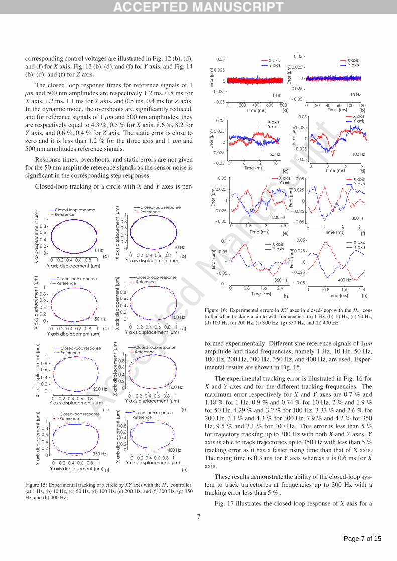
formed experimentally. Different sine reference signals of 1μmamplitude and fixed frequencies, namely 1 Hz, 10 Hz, 50 Hz,100 Hz, 200 Hz, 300 Hz, 350 Hz, and 400 Hz, are used. Exper-imental results are shown in Fig. 15.
The experimental tracking error is illustrated in Fig. 16 forX and Y axes and for the different tracking frequencies. Themaximum error respectively for X and Y axes are 0.7 % and1.18 % for 1 Hz, 0.9 % and 0.74 % for 10 Hz, 2 % and 1.9 %for 50 Hz, 4.29 % and 3.2 % for 100 Hz, 3.33 % and 2.6 % for200 Hz, 3.1 % and 4.3 % for 300 Hz, 7.9 % and 4.2 % for 350Hz, 9.5 % and 7.1 % for 400 Hz. This error is less than 5 %for trajectory tracking up to 300 Hz with both X and Y axes. Yaxis is able to track trajectories up to 350 Hz with less than 5 %tracking error as it has a faster rising time than that of X axis.The rising time is 0.3 ms for Y axis whereas it is 0.6 ms for Xaxis.
These results demonstrate the ability of the closed-loop sys-tem to track trajectories at frequencies up to 300 Hz with atracking error less than 5 % .
Fig. 17 illustrates the closed-loop response of X axis for a
7

Page 8 of 15
Accep
ted
Man
uscr
ipt
-5
0
5
10
Closed-loop responseReferenceX
axi
s d
ispla
ce
me
nt
(μm
)
Time (s)0 2 4 6 81 3 5 7
Figure 17: X axis closed-loop response for a reference square signal of 5 nmamplitude with the scanning controller.
square reference signal of 5 nm amplitude. This experimentaldisplacement curve shows the achievable positioning resolutionof these actuators in scanning mode using the H∞ controllers.
4. Control in stepping mode
The objective of the stepping mode control is to performa positioning with a large range displacement, i.e micrometerand millimeter ranges. To this end, a f /u proportional controlstrategy [29] is designed.
4.1. Mixed stepping / scanning dynamic modeling
The open-loop system is illustrated in Fig. 18, where xp(t)and xs(t) are respectively the PE and the slider displacements,vx(t) is the input voltage of the PE and F f (t) is the friction forcebetween the PE and the slider. CH is a static conversion coef-ficient. The nonlinear model involves the static hysteresis H,the dynamic model of the PE and that of the slider and the non-linear dynamic of the friction force. More details about thenon-linear mixed stepping/scanning modeling can be found inthe previous work [38]. This model is well adapted for the def-inition of stepping control parameters.
PE dynamics
slider dynamics
Hysteresis
Friction
CH
Dead-zone
+
_
vx(t)xp(t)
xs(t)Ff(t)xp(t)xs(t)
Figure 18: Block diagram of the open-loop input/output transfer in steppingmode.
4.2. Stepping mode control
4.2.1. f /u proportional control
The closed-loop f /u proportional control scheme is shownin Fig. 19. It includes the PSS actuator to be controlled, a home
made sawtooth generator based on an arduino due, an ampli-tude proportional controller gain Kux and a frequency propor-tional controller gain Kf x.
The sawtooth generator has three inputs, namely the volt-ages ux(t), fx(t) and dx(t) to set respectively the amplitude, thefrequency and the direction of the sawtooth voltage vx(t) at eachsampling time. The amplitude and the frequency of vx(t) canvary in the ranges [0 - 5V] and [few Hz - 20 kHz ] respectively.The voltage vx(t) is amplified by a linear amplifier with a gainof 20 to feed the PE.
xr(t) xs(t)ex(t)
.
.
Abs
Abs
Kux
Kfx
us
fs
+1
-1
Saturation
Saturation
Sgn
PSS
ux(t)
fx(t)
dx(t)
vx(t)
Sawtooth generator
+_
Figure 19: Closed-loop f /u proportional control scheme of the PSS actuator instepping mode.
4.2.2. Experimental results
The f /u proportional controllers are designed for the threeaxes of the Cartesian nano-robot (Fig. 1). The control gains Kux
and Kf x are defined experimentally by trial and error to havea good compromise between the positioning precision and thevibration damping. The gains have been defined for a posi-tion reference of 1 mm and the same gains have been used forall the experiments performed thereafter, i.e. for different in-put references and for the three nano-robot axes. The samplingfrequency is 25 kHz.
Step references of 1 mm, 100 μm, 50 μm, and 5 μm are usedfor the validation. Fig. 20 shows experimental results for X axis.The response time is equal to 26.9 ms (resp. 3.8 ms, 2.5 ms, 2.4ms) for a reference signal of 1 mm (resp. 100 μm, 50 μm, and5 μm) amplitude. Fig. 21 shows the experimental results for Yaxis. The response time is equal to 40.7 ms (resp. 4.7 ms, 2.8ms, 2.7 ms) for a reference signal of 1 mm (resp. 100 μm, 50μm, and 5 μm) amplitude. Fig. 22 shows the experimental re-sults for Z axis. The response time is equal to 27.7 ms (resp.3.4 ms, 1.9 ms, 1.1 ms) for a reference signal of 1 mm (resp.100 μm, 50 μm, and 5 μm) amplitude. Static errors are close tozero for the three axes and for the reference signals of differ-ent amplitudes. The displacement curves are smooth thanks tothe ability of the arduino due card and the defined algorithm togenerate sawtooth voltages at relatively high frequencies up to20 kHz. As such, the stick and slip phases are almost invisible.
The f /u proportional controller always feed the actuatorwith a sawtooth voltage. It ensures good tracking performancesbut for displacements lower than the maximum elongation ofthe PE, i.e. less than 2 μm. In this case, the scanning controllerprovides better positioning results mainly in terms of resolutionas it will be shown in the sequel. In an ideal case, a global
8

Page 9 of 15
Accep
ted
Man
uscr
ipt
Time(ms)0 10 20 30 40 50 60
X a
xis
disp
lac
em
en
t (μ
m)
0
200
400
600
800
1000
Time(ms)0 2 4 6 8 10 12X
axi
s d
ispla
ce
me
nt
(μm
)
0
20406080100
Time(ms)0 2 4 6 8 10 12
X a
xis
disp
lac
em
en
t (μ
m)
01020304050
Time(ms)0 2 4 6 8 10 12
axi
s d
ispla
ce
me
nt
(μm
)
012345
Closed-loop responseReference
Closed-loop responseReference
Closed-loop responseReference
Closed-loop responseReference
(a) (b)
(c) (d)
Figure 20: Experimental displacement of the X axis in closed-loop with the f /uproportional controller for step reference signals of amplitude: (a) 1000 μm, (b)100 μm, (d) 50 μm, and (e) 5 μm.
Time(ms)0 10 20 30 40 50 60 70 80Y
axi
s d
ispla
ce
me
nt
(μm
)
0
200
400
600
800
1000
Time(ms)0 2 4 6 8 10 12
Y a
xis
disp
lac
em
en
t (μ
m)
0
20
40
60
80
100
Time(ms)0 2 4 6 8 10 12
Y a
xis
disp
lac
em
en
t (μ
m)
0
10
20
30
40
50
Time(ms)0 2 4 6 8 10 12
Y a
xis
disp
lac
em
en
t (μ
m)
0
1
2
3
4
5
Closed-loop responseReference
Closed-loop responseReference
Closed-loop responseReference
Closed-loop responseReference
(a) (b)
(c) (d)
Figure 21: Experimental displacement of the Y axis in closed-loop with the f /uproportional controller for step reference signals of amplitude: (a) 1000 μm, (b)100 μm, (d) 50 μm, and (e) 5 μm.
Time(ms)0 2 4 6 8 10 12Z
axi
s d
ispla
ce
me
nt
(μm
)
020
40
60
80
100
Time(ms)0 10 20 30 40 50 60 70 80
Z a
xis
disp
lac
em
en
t (μ
m)
02004006008001000
Time(ms)0 2 4 6 8 10 12
Z a
xis
disp
lac
em
en
t (μ
m)
0
10
20
30
40
50
Time(ms)0 2 4 6 8 10 12
Z a
xis
disp
lac
em
en
t (μ
m)
0
1
2
3
4
5
Closed-loop responseReference Closed-loop response
Reference
Closed-loop responseReference
Closed-loop responseReference
(a) (b)
(c) (d)
Figure 22: Experimental displacement of the Z axis in closed-loop with the f /uproportional controller for step reference signals of amplitude: (a) 1000 μm, (b)100 μm, (d) 50 μm, and (e) 5 μm.
control structure should be able to switch between the steppingcontroller to the scanning controller when the required displace-ments are in the range of the elongation of the PE. This switchmust be transparent for the user. In other words, the aim is to beable to perform positioning tasks with millimeter or micrometerrange displacements and a nanometer resolution without worry-ing about the mode of operation of the actuator.
5. Mixed stepping/scanning mode control
5.1. Switching control problem
To deal with the transition between the coarse and the finepositioning of the nano-robot in a transparent way, a switch con-trol strategy between the stepping and the scanning controllersin needed. Even if the switch is stable, the bump transfer atswitching time can generate undesired vibrations of the actu-ator due to the discontinuity of the control voltage of the twocontrollers. The generated oscillations can damage the end ef-fector of the nano-robot or the object to be manipulated.
X a
xis
disp
lac
em
en
t (μ
m)
Time (s)0 0.02 0.040.01 0.03
0
0.5
1
1.5
2
Switch region
Figure 23: The closed-loop X axis displacement with the controller providedby SmarAct company. The maximum elongation of the PE is between 1 μmand 1.5 μm while the input reference is 2 μm. When the position of the sliderexceeds the maximum elongation of the PE, vibrations are produced due to aslip phase.
For instance, Let us consider the mechanical characteriza-tion task of mico-membranes of [12]. The end effector is atungsten probe attached on the Z axis. It is brought closeto the micro-membrane in a semi-automated way: (i) It is ap-proached from few millimeters distance to few micrometers dis-tance in a coarse mode. (ii) It is thereafter controlled using theSmarAct controller to bring it from few micrometer distance tofew nanometers distance. This characterization gives satisfac-tory results, but it is time consuming. Moreover the transitionfrom stepping mode to scanning mode generate significant vi-brations of around 100 nm as shown in Fig. 23 while the micro-membranes are 200 nm thin.
5.2. Control principle
Switched controllers have to provide control outputs withan equal first derivative at the switching time to avoid a bumptransfer. The issue for PSS actuators is that it is necessary todeal with a system that has two operating modes. The first oneis the scanning mode alone. The second is the stepping modethat includes a succession of scanning modes.
The structure of the proposed mixed stepping/scanning modecontrol is shown in Fig. 24. It includes the H∞ scanning con-troller, the f /u proportional stepping controller and the internal
9

Page 10 of 15
Accep
ted
Man
uscr
ipt
xr(t) xs(t)ex(t)
.
.
Abs
Abs
Kux
Kfx
us
fs
+1
-1
Saturation
Saturation
Sgn
ux(t)
fx(t)
dx(t)
vx(t)
Sawtooth generator
+_
1
2
1
2
PSS
Saturation
Kx(s)
Switch 1Switch 2
Gnx(s)
+_
Switch condition m (t)
Figure 24: The mixed stepping/scanning control strategy for PSS actuators.The dashed bloc includes the elements that are implemented in the processorboard for the experimental validation.
model of the actuator Gnx(s) to deal with the bumpless switch-ing. The aim is to to mitigate vibrations at the switching timeand to satisfy closed-loop stability.
Each PSS actuator can be controlled as follows:
-Stepping mode control-: the PSS actuator is initially con-trolled using the f /u proportional controller designed in section4. The nominal model Gnx(s) (see section 3.1.3) is meanwhileused when the scanning controller Kx is offline. In this case, theposition reference of the offline controller is the current positionxs(t) of the actuator. During the Stepping control, the Switch1 is on position 1 and and the Switch 2 is on position 2. Theswitch condition is defined by the user.
- Mixed stepping/scanning mode control-: Thanks to theclosed-loop system composed of Kx and Gnx with the referenceposition xs, during the stepping mode control, the control volt-age value of the scanning mode controller approaches that ofthe stepping mode controller so that at switching time, the tran-sition between the two control voltages is smooth.
-Scanning mode control-: the Switch 1 is on position 2and Switch 2 is on position 1. The actuator is controlled inscanning mode only using the H∞ controller designed in section3.2.2. The position reference is in this case xr. Precise and fastpositioning of the actuator can be achieved.
The mixed structure presented above can simultaneouslymanage the two operating modes of the actuator. Its main ad-vantage consists in the fact that the user has not to specify thewell-suited operating mode according to the desired task, as itis automatically done by the mixed control strategy. This is anovelty in control of PSS actuators. Experimental validationsare presented in the following section.
5.3. Experimental results
The real time implementation of the control is done on Xand Y axes of the Cartesian nano-robotic system of Fig. 1. The
Time(s)0 5 10 15 20 25X
axi
s d
ispla
ce
me
nt
(μm
)
0
5
10
15
20
Time(s)0 5 10 15 20 25Y
axi
s d
ispla
ce
me
nt
(μm
)0
5
10
15
20
Closed-loop responseReferenceInput signal for the switch condition
Closed-loop responseReferenceInput signal for the switch condition
Time(s)18.5 19 19.5 20 20.5X
axi
s d
ispla
ce
me
nt
(μm
)
0
0.5
1
1.5
Time(s)18.5 19 19.5 20 20.5 21Y
axi
s d
ispla
ce
me
nt
(μm
)
0
0.5
1
1.5
(I)
(III)
(II)
(I)
(III)
(a)
(b)
m(t)
m(t)
Stepping
Scanning
Figure 25: Closed loop response of X axis (a) and Y axis (b) to a 1 Hz sinusoidalreference position with a deceasing amplitude. The switch from the steppingmode to the scanning mode happens when the input signal m(t) for the switchcondition is less than 1.2 μm.
latter is operating inside the SEM vacuum chamber.
The parts inside the dashed bloc of Fig. 24 are implementedon the processor board. Different parameters such as those ofthe reference signal xr(t) and the switch condition can be set andchanged in real time thanks to the human-machine interface.The signals ux(t), fx(t) and dx(t) are calculated by the controllerand connected at the input of the sawtooth generator throughDAC (Digital To Analog) converters of 16 bit resolution and 1.6μs sample time. The current position of the actuator measuredby the integrated optical encoder is fed back to the controllerthanks to a an incremental encoder interface board.
The reference trajectory selected for the experimental testof the mixed controller is a sinusoidal signal of 1 Hz frequencyand a decreasing amplitude from 20 μm to less than 1 μm asshown in Fig. 25. Let m(t) be the straight line passing throughthe peaks of the reference signal (Fig. 25). The switch from thestepping control to the scanning control is performed when m(t)< 1.2 μm. The controller is implemented with 25 kHz samplingfrequency.
Experimental results are presented in Fig. 25 (a) Fig. 25 (b)and for X and Y axes respectively. The nano-robot axes are ac-tuated with the f/u proportional controller when m(t) >= 1.2 μmand with the H∞ controller otherwise. Three main vibrations
10

Page 11 of 15
Accep
ted
Man
uscr
iptTime(s)
18.5 19 19.5 20 20.5Y a
xis
disp
lac
em
en
t (μ
m)
0
0.2
0.4
0.6
0.8
1
Time(s)19.35 19.45 19.55 19.65 19.75 19.85
Y a
xis
disp
lac
em
en
t (μ
m)
0.2
0.22
0.24
0.26
Closed-loop response with mixed stepping/scanning controlClosed-loop response with stepping control only
Enlarged view
Switch for the mixed control
Figure 26: Closed-loop response of Y axis with the mixed stepping/scanningcontrol and the stepping control only.
can be observed as shown in Fig. 25. The vibration (I) is dueto the switch from the stepping to the scanning controller. Itsamplitude is lower than 80 nm for X axis and almost unobserv-able for Y axis. The vibration (II) happens during the steppingcontrol, it is due to the slip phase when the PE exceeds its max-imum elongation. The vibration (III) is due to the switch fromthe scanning to the stepping controller. This vibration occurssince the bumpless switch from the scanning to the steppingmode control is not considered in this paper.
Some experimental issues occur. The results of Fig. 25 arenot always reproducible. For instance, if the switch from thestepping to the scanning mode control happens when the con-trol voltage is close to 0 V or 100 V (i.e. the limits of inputvoltage of the PE), the PE has not enough displacement rangeto follow the reference trajectory. In this case the switch is pro-duced with vibrations. This is one of the probable reasons of thereproducibility issue. Nevertheless, several experiments havegiven very satisfactory results similar to those of Fig. 25. Thereproducibility of the experiments will be investigated in futureworks.
In a second time, the nano-robot axes are controlled onlyin stepping mode (i.e. without switch) for the same referenceposition xr(t). The results for Y axis are presented in Fig. 26and compared with those obtained using the mixed stepping /scanning control. For displacements lower than 1 μm, the use ofa scanning control (H∞ in the case of the study) allows reachingthe sensor resolution (i.e. 5 nm), while the resolution obtainedif only the stepping control is used is around 25 nm. The otheradvantage to use a scanning controller in the fine positioningmode and hence a switch strategy is that it offers the possibilityto set precisely the closed loop specifications during the controldesign which is not the case when the actuator is controlled withonly a sawtooth type voltage.
Experimentations have shown that the new mixed stepping/scanning control strategy can perform stable and smooth switchbetween two controllers of different structures. This controllercan guarantee fully-automated nano-robotic applications whenmillimeter or micrometer range displacements with a nanome-ter resolution are required.
6. Conclusion
Nanotechnologies are increasingly requiring robotics at thenanometer scale. SEM-integrated nano-robotic systems havetherefore emerged to perform the main required tasks, suchas nano-manipulation, nano-assembly, electrical characteriza-tion and mechanical characterizations. The PSS actuator isone of the best candidates in nano-robotics because it is ableto perform long-range coarse displacements in stepping modeand fine displacements with a nanometer resolution in scanningmode. Control of these actuators is challenging due to severalreasons among which the hybrid stepping/scanning operatingmodes. This paper has focused on the control of PSS actu-ators to perform large range motions with a nanometer rangeresolution. A H∞ controller has been firstly designed in scan-ning mode to satisfy multi-objective criteria in terms of stabil-ity robustness w.r.t hysteresis and the measurement time delay,closed loop bandwidth and precision. A f /u proportional con-troller has then been designed to control the actuators in a largemotion range in stepping mode. A new mixed control strategyable to switch from the stepping control mode to the scanningcontrol mode has been thereafter proposed to drive the PSS ac-tuators in a mixed stepping/scanning operating mode. Experi-mental results have demonstrated the effectiveness of the con-troller and have therefore opened new perspectives for the ca-pability of automated nano-robotics. Futur works will concernthe extension of the control method to deal with tracking per-formance of the switch from the scanning mode to the steppingmode.
7. Acknowledgment
The authors would like to thank Georges Daher, phd studentat Sorbonne Universite, for the complete design and program-ming of the sawtooth generator based on arduino due. Thiswork has been partially sponsored by the French governmentresearch program Investissements d’avenir through the Robo-tex Equipment of Excellence (ANR-10-EQPX-44)
References
[1] M. Takahashi, H. Ko, T. Ushiki, F. Iwata, Interactive nano manipulatorbased on an atomic force microscope for scanning electron microscopy,International Symposium on Micro-NanoMechatronics and Human Sci-ence (MHS) (2011) 495–500.
[2] S. Qin, T. Kim, Z. Wang, A. Li, Nanomanipulation and nanofabricationwith multi-probe scanning tunneling microscope: From individual atomsto nanowires, Review of Scientific Instruments 83 (6) (2012) 063704.
[3] V. Eichhorn, M. Bartenwerfer, S. Fatikow, Nanorobotic assembly andfocused ion beam processing of nanotube-enhanced afm probes, IEEETransactions on Automation Science and Engineering 9 (4) (2012) 679–686.
11

Page 12 of 15
Accep
ted
Man
uscr
ipt
[4] Z. Yang, M. Nakajima, Y. Shen, T. Fukuda, Assembly and evaluation ofmwcnts probe thermal sensor by nanorobotic manipulation, 12th IEEEConference on Nanotechnology (2012) 1–4.
[5] Y. Zhang, Z. Liang, R. Yong, C. Changhai, K. Brandon, Y. Sun, A load-lock-compatible nanomanipulation system for scanning electron micro-scope, IEEE/ASME Transactions on Mechatronics 18 (1) (2013) 230–237.
[6] S. Boles, A. Sedlmayr, O. Kraft, R. Monig, In situ cycling and mechanicaltesting of silicon nanowire anodes for lithium-ion battery applications,Applied Physics Letters 100 (24) (2012) 243901.
[7] C.Ru, Y. Zhang, Y. Sun, Y. Zhong, X. Sun, D. Hoyle, I. Cotton, Auto-mated four-point probe measurement of nanowires inside a scanning elec-tron microscope, IEEE Transactions on Nanotechnology 10 (4) (2011)674–681.
[8] Y. Wang, J. Zhu, M. Pang, J. Luo, S. Xie, M. Liu, L. Sun, C. Zhou, ,M. Tan, J. Ge, et al., A stick-slip positioning stage robust to load vari-ations, IEEE/ASME Transactions on Mechatronics 21 (4) (2016) 2165–2173.
[9] G.-Y. Gu, L.-M. Zhu, C.-Y. Su, H. Ding, S. Fatikow, Modeling and controlof piezo-actuated nanopositioning stages: A survey, IEEE Transactionson Automation Science and Engineering 13 (1) (2016) 313–332.
[10] Y. Li, Q. Xu, Adaptive sliding mode control with perturbation estimationand pid sliding surface for motion tracking of a piezo-driven micromanip-ulator, IEEE Transactions on Control Systems Technology 18 (4) (2010)798–810.
[11] T. Lu, M. Boudaoud, D. Heriban, S. Regnier, Nonlinear modeling fora class of nano-robotic systems using piezoelectric stick-slip actuators,IEEE/RSJ International Conference on Intelligent Robots and Systems(2015) 6020–6025.
[12] J. Abrahamians, B. Sauvet, J. Polesel-Maris, R. Braive, S. Regnier, Ananorobotic system for in situ stiffness measurements on membranes,IEEE Transactions on Robotics 30 (1) (2014) 119–124.
[13] G. Wang, G. Chen, F. Bai, High-speed and precision control of a piezo-electric positioner with hysteresis, resonance and disturbance compensa-tion, Microsystem Technologies 22 (10) (2016) 2499–2509.
[14] G.-Y. Gu, L.-M. Zhu, C.-Y. Su, Modeling and compensation of asym-metric hysteresis nonlinearity for piezoceramic actuators with a modi-fied prandtl–ishlinskii model, IEEE Transactions on Industrial Electronics61 (3) (2014) 1583–1595.
[15] X. Zhou, J. Zhao, G. Song, J. A. De Abreu-Garcia, Preisach modelingof hysteresis and tracking control of a thunder actuator system, SmartStructures and Materials 2003: Modeling, Signal Processing, and Control5049 (2003) 112–126.
[16] K. Kuhnen, H. Janocha, Inverse feedforward controller for complex hys-teretic nonlinearities in smart-material systems, Control and IntelligentSystems 29 (3) (2001) 74–83.
[17] M. Rakotondrabe, Bouc–wen modeling and inverse multiplicative struc-ture to compensate hysteresis nonlinearity in piezoelectric actuators,IEEE Transactions on Automation Science and Engineering 8 (2) (2011)428–431.
[18] S. R. Moheimani, A survey of recent innovations in vibration dampingand control using shunted piezoelectric transducers, IEEE transactions oncontrol systems technology 11 (4) (2003) 482–494.
[19] M. Rakotondrabe, C. Clevy, P. Lutz, Complete open loop control of hys-teretic, creeped, and oscillating piezoelectric cantilevers, IEEE Transac-tions on Automation Science and Engineering 7 (3) (2010) 440–450.
[20] L. Li, C.-X. Li, G. Gu, L.-M. Zhu, Positive acceleration, velocity andposition feedback based damping control approach for piezo-actuatednanopositioning stages, Mechatronics 47 (2017) 97 – 104.
[21] A. J. Fleming, S. S. Aphale, S. R. Moheimani, A new method for robustdamping and tracking control of scanning probe microscope positioningstages, IEEE Transactions on Nanotechnology 9 (4) (2010) 438–448.
[22] M.-S. Tsai, J.-S. Chen, Robust tracking control of a piezoactuator usinga new approximate hysteresis model, Journal of dynamic systems, mea-surement, and control 125 (1) (2003) 96–102.
[23] A. Sebastian, S. M. Salapaka, Design methodologies for robust nano-positioning, IEEE Transactions on Control Systems Technology 13 (6)(2005) 868–876.
[24] M. Al Janaideh, M. Rakotondrabe, O. Aljanaideh, Further results on hys-teresis compensation of smart micropositioning systems with the inverseprandtl–ishlinskii compensator, IEEE Transactions on Control Systems
Technology 24 (2) (2016) 428–439.[25] H. C. Liaw, B. Shirinzadeh, J. Smith, Enhanced sliding mode motion
tracking control of piezoelectric actuators, Sensors and Actuators A:Physical 138 (1) (2007) 194–202.
[26] I. R. Petersen, H. R. Pota, Minimax LQG optimal control of a flexiblebeam, Control Engineering Practice 11 (11) (2003) 1273–1287.
[27] J.-M. Breguet, R. Clavel, Stick and slip actuators: design, control, perfor-mances and applications, Micromechatronics and Human Science, 1998.MHS’98. Proceedings of the 1998 International Symposium o.
[28] B. Sedghi, Control design of hybrid systems via dehybridization, EPFL.[29] M. Rakotondrabe, Y. Haddab, P. Lutz, Voltage/frequency proportional
control of stick-slip micropositioning systems, IEEE Transactions onControl Systems Technology 16 (6) (2008) 1316–1322.
[30] R. Oubellil, A. Voda, M. Boudaoud, S. Regnier, A 2-dof H∞ control strat-egy for a 3 axes robotic system operating at the nanometer scale, 20thInternational Conference on System Theory, Control and Computing (IC-STCC) (2016) 355–362.
[31] S. Billings, Identification of nonlinear systems–a survey, IEE ProceedingsD (Control Theory and Applications) 127 (6) (1980) 272–285.
[32] K. Kuhnen, Modeling, identification and compensation of complex hys-teretic nonlinearities: A modified prandtl-ishlinskii approach, Europeanjournal of control 9 (4) (2003) 407–418.
[33] M. Grossard, M. Boukallel, N. Chaillet, C. Rotinat-Libersa, Modeling androbust control strategy for a control-optimized piezoelectric microgripper,IEEE/ASME Transactions On Mechatronics 16 (4) (2011) 674–683.
[34] M. Rakotondrabe, Y. Haddab, P. Lutz, Quadrilateral modelling and ro-bust control of a nonlinear piezoelectric cantilever, IEEE Transactions onControl Systems Technology 17 (3) (2009) 528–539.
[35] R. Oubellil, A. Voda, M. Boudaoud, S. Regnier, Robust control strategiesof stick-slip type actuators for fast and accurate nanopositioning opera-tions in scanning mode, 23th Mediterranean Conference on Control andAutomation (MED) (2015) 650–655.
[36] P. Apkarian, Elements de la theorie de la commande robuste.[37] J. C. Doyle, K. Glover, P. P. Khargonekar, B. A. Francis, State-space solu-
tions to standard H2 and H∞ infinity/control problems, IEEE Transactionson Automatic control 34 (8) (1989) 831–847.
[38] M. Boudaoud, S. Liang, T. Lu, R. Oubellil, S. Regnier, Voltage/frequencyrate dependent modeling for nano-robotic systems based on piezoelec-tric stick-slip actuators, IEEE/RSJ International Conference on IntelligentRobots and Systems (IROS) (2016) 5297–5303.
12

Page 13 of 15
Accep
ted
Man
uscr
ipt
Highlights
• Comprehensive modeling of Piezoelectric Stick-Slip (PSS) actuators to accurately describe
both scanning and stepping operating modes.
• A multi-criteria robust control strategy in scanning mode ensures positioning with motion
range from few nanometers to few micrometers, and nanometer resolution.
– It satisfies a good compromise between closed-loop bandwidth and vibration damping.
– It guarantees stability robustness against hysteresis and uncertain measurement time-
delay.
• A frequency/amplitude controller ensures precise positioning with displacement range from
few tens micrometers to few millimeters.
• A new mixed stepping/scanning mode control strategy guarantees accurate positioning with
displacement range from few nanometers to few millimeters.
– It is able to switch between the scanning and stepping modes while guaranteeing closed-
loop stability and bumpless at switching time.
– It opens new perspectives to the use of the PSS actuators in fully-automated nano-robotic
applications inside a Scanning Electron microscope (SEM).
1

Page 14 of 15
Accep
ted
Man
uscr
ipt
Authors biography
Raouia Oubellil received an engineer degree in control systems from National polytechnic school
of Algiers, Algeria, in 2012. She is also graduated master 2 Research in control systems, signal and
image processing from Ecole Normale Superieure de Cachan, Paris, France, in 2013. She obtained
a PhD degree in control systems from the University of Grenoble Alpes, in 2016. She is actually a
teaching assistant at the University of Franche-Comte (UFC), and a research assistant at FEMTO-
ST Institute, Besanon, France. Her primary research interest is in robust control. More specifically,
robust control of a nanorobotics system.
Alina Voda received the Diploma degree in energy engineering from the Polytechnical University
of Bucarest, Bucarest, Romania, and the Ph.D. degree in control from the Polytechnical Institute of
Grenoble, Grenoble, France, in 1987 and 1994, respectively. She was a Nuclear Power Engineer with
Cernavoda Nuclear Plant, and then with the Research Center for Energy, Bucarest, until 1990. She
was an Assistant Professor in control with University Joseph Fourier, Grenoble, in 1995, where she is
still serving as an Associate Professor. She was also with Pechiney Research Center, Voiron, France,
in 2001. Her current research interests are held at the Control Systems Department of GIPSA-lab
and cover various control/identification problems, as well as different application fields either in
1

Page 15 of 15
Accep
ted
Man
uscr
ipt
industry or in sciences (electro-mechanical systems, micro/nano-sciences).
Mokrane Boudaoud received the engineering degree in automatic control from the University
of science and technology Houari Boumediene (USTHB, Algiers, Algeria), and a MS degree in
mechatronics and microrobotics at the University of Franche-Comte (UFC, Besanon, France) in
2009. He received in 2012 the PhD degree in control engineering at AS2M (Automatic Control and
Micro-Mechatronic Systems) department of Femto-st Institute. He is currently Associate Professor
at University Pierre et Marie Curie / Institut des Systemes Intelligents et de Robotique. His field
of interest includes modeling and robust control of multi-degree-of-freedom nano-robotic systems
operating under a scanning electron microscope (SEM).
Stephane Regnier received his PhD degree in Mechanics and Robotics from the University of
Pierre and Marie Curie, Paris, France in 1996. He is currently Professor at the Institute of Intelligent
Systems and Robotics (ISIR), University of Pierre and Marie Curie, Paris, France. He has been head
of the ISIR micromanipulation team since 2001. His research interests are focused on micro and nano
manipulation, teleoperation and haptic feedback at the nanoscale, micromechatronics and biological
cell characterization.
2