Mixed-Signal- · PDF fileStephan Henzler Mixed -Signal Electronics 2011/12 ......
26
Stephan Henzler Mixed-Signal-Electronics 2011/12 Mixed-Signal-Electronics PD Dr.-Ing. Stephan Henzler 1
Transcript of Mixed-Signal- · PDF fileStephan Henzler Mixed -Signal Electronics 2011/12 ......

Stephan Henzler Mixed-Signal-Electronics 2011/12
Mixed-Signal-Electronics
PD Dr.-Ing. Stephan Henzler
1

Stephan Henzler Mixed-Signal-Electronics 2011/12
2

Stephan Henzler Mixed-Signal-Electronics 2011/12
3

Stephan Henzler Mixed-Signal-Electronics 2011/12
4

Stephan Henzler Mixed-Signal-Electronics 2011/12
5
Stephan Henzler Mixed-Signal-Electronics 2011/12
6

Stephan Henzler Mixed-Signal-Electronics 2011/12
Comparators
7
Chapter 7

Stephan Henzler Mixed-Signal-Electronics 2011/12
Ideal Comparator
Compare input signal to reference and provide binary output
signal
Often same symbol as for opamp
(reasonable as open loop opamp behaves like a comparator)
Comparator is essentially an amplifier with saturation,
ideal comparator means infinite gain in VCVS not realistic
8

Stephan Henzler Mixed-Signal-Electronics 2011/12
Comparator gain
Maximum voltage for negative saturation VDL
Minimum voltage for positive saturation VDH
Comparator resolution: (min. voltage increment, determines comparator gain)
Offset voltage: Horizontal shift of characteristic
Input common mode range
Static Characteristics of Comparator
9

Stephan Henzler Mixed-Signal-Electronics 2011/12
Dynamic Characteristics of Comparator
Note:
Comparators work in large signal mode of operation
– basic circuit theory to reveal trade-offs and mechanisms
– simulation to determine actual performance figures
Main dynamic performance figure: propagation delay td
10

Stephan Henzler Mixed-Signal-Electronics 2011/12
Operational Amplifier as Comparator
Opamp in open-loop configuration is comparator
– asynchronous
– relatively slow due to high gain and stability requirement
– offset error (may be compensated by correlated double sampling,
but this also means synchronous operation)
– Consider DC operating point at input for a reference voltage ≠ 0
– Compensation cap may be disconnected during latching
11

Stephan Henzler Mixed-Signal-Electronics 2011/12
OpAmp Comparator Dynamics
Gain-Bandwidth trade-off
– gain determined by desired resolution
– bandwidth determined by desired propagation delay
Amplifier model
Step response
Propagation Delay
12
0 2 4 6 8 100
0.1
0.2
0.3
0.4
0.5
0.6
0.7
0.8
0.9
1
time [AU]
outp
ut sig
nal [n
orm
]
Response of Stable 1st Order Linear System
-0.1
-0.5
-1.0
-2.0
-2.0
-0.5
-1.0
-0.1

Stephan Henzler Mixed-Signal-Electronics 2011/12
Comparator Propagation Delay
Linear mode of operation
Propagation delay for small input signals is determined by
linear small signal dynamics of amplifier
Slew rate limited mode of operation
Propagation delay for large input signals is dominated by
slew rate of opamp output stage
Propagation delay for slew rate limited operation
13

Stephan Henzler Mixed-Signal-Electronics 2011/12
Discrete Time Comparators
In some applications comparator function only desired
– during certain intervals
– at certain discrete time instances
Allows for offset compensation via auto-zeroing
and other switched capacitor benefits
Allows for amplifiers in positive feedback configuration
– full level always reached
– gain boosting (reuse one amplifier by cyclic amplification
14

Stephan Henzler Mixed-Signal-Electronics 2011/12
Track & Latch Circuit I
15

Stephan Henzler Mixed-Signal-Electronics 2011/12
Track & Latch Circuit II
16

Stephan Henzler Mixed-Signal-Electronics 2011/12
Principle of Track-and-Latch Stage
17

Stephan Henzler Mixed-Signal-Electronics 2011/12
Linear Dynamic of Latch
Linear small signal analysis (ref. Schaltungstechnik 2)
Node voltages
Differential voltage
Propagation delay
18
0 0.5 1 1.5 2 2.5 3 3.5 40
0.1
0.2
0.3
0.4
0.5
0.6
0.7
0.8
0.9
1
time [AU]
outp
ut sig
nal [n
orm
]
Response of Instable 1st Order Linear System (Latch)
0.01
0.1
0.4

Stephan Henzler Mixed-Signal-Electronics 2011/12
Latched Comparators I
Standard architecture for high-speed comparators
Latch offset voltage limits resolution of latch-only comparator
Two step approach:
– analog pre-amplifier stage(s)
– regenerative track and latch stage
19

Stephan Henzler Mixed-Signal-Electronics 2011/12
Latched Comparators II
Pre-amplifier:
– 1-3 amplifier stages
– low gain, high-speed
– delay along amplifier chain
– separation of input from latch to reduce loading and avoid
kickback effect
20

Stephan Henzler Mixed-Signal-Electronics 2011/12
Latched Comparators III
Track & latch circuit:
– amplifies signal in track mode
– restores (regenerates) signal to full rail in regenerative
latch mode (positive feedback)
21

Stephan Henzler Mixed-Signal-Electronics 2011/12
Input Referred Offset of Latch
Input referred offset error of latch stage is reduced by gain A
of pre-amplifier
22

Stephan Henzler Mixed-Signal-Electronics 2011/12
Current Mode (CML) Latch
Combines amplifier and
latch functionality
23

Stephan Henzler Mixed-Signal-Electronics 2011/12
Memory and Hysteresis in Comparators
Hysteresis:
Switching threshold is different when switching from low to
high and from high to low, respectively.
Useful to avoid bouncing outputs for small (noisy) signals
near comparator threshold
Memory effect:
Kind of hysteresis that causes the comparator decision to be
dependent on previous decisions.
Has to be strongly avoided in Nyquist rate ADCs such as
flash converters. 24
Stephan Henzler Mixed-Signal-Electronics 2011/12
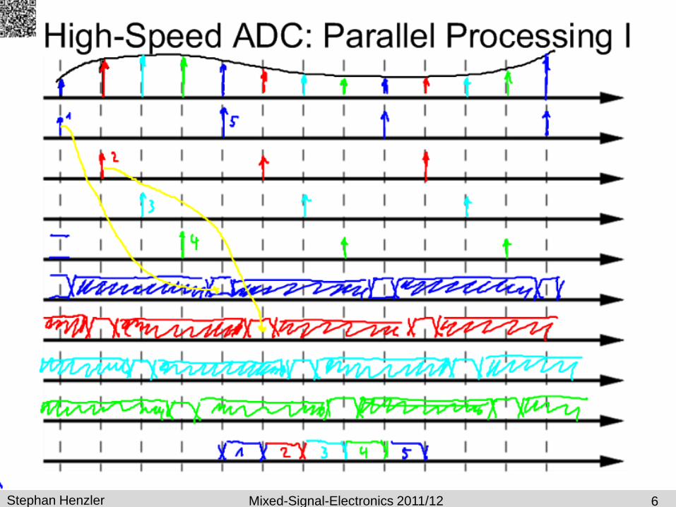
Elimination of Memory Effect
Precharge and equalize circuit elements eliminate all
information from previous cycles and decisions
25

Stephan Henzler Mixed-Signal-Electronics 2011/12
Switched Capacitor Comparator
Offset compensated
Threshold determined by capacitynce ratio
26