Mixed-Mode Fracture Investiga~ions Interface Cracks in ... · Mixed-Mode Fracture Investiga~ions of...
18
M. M eyer, * S. Schmauder, * and G. Eissner* Mixed-Mode Fracture Investiga~ions of Interface Cracks in Dissimilar Media REFERENCE Meyer, M., Schmauder, S., and Eissner, G., Mixed-mode fracture investigatioos of interface cracks in dissimilar media. Mixed-Mode Fatigue and Fracture, ESIS 14 (Edited by H. P. Rossmanith and K. J. Miller) 1993, Mechanical Engineering Publications, London, pp. 303-318. Abstract The stress field of an interface crack depends on the thermo-elastic mismatch of the bonded bodies. Thus, interface cracks in dissimilar media experience local mixed-mode loading, even when the structure is remotely loaded in pure tension. This property can lead to crack kinking out of the interface, preventing reliable interface toughness tests. In this paper the near tip stress field of an interface crack in bimaterials is evaluated in order to obtain a proper mixed-mode fracture criterion for bimaterials. The evaluation is based on the circumferential stress criterion given by ErdoganjSih (1) for homogeneous materials. An extended virtual crack extension technique for calculating single mode stress intensity factors KI (i = I, 11)is presented and discussed. Finally, a modified compact tension shear loading device for testing bimaterials is introduced. The corresponding calibration functions Yk and local phase angles t/I for this geometry are presented and discussed with respect to a systematic variation of elastic proper- ties, crack length ratios, and applied mixed-mode loads. NotatioD K Complex interface stress intensity factor KIc Mode I fracture toughness KI.II Mode I, II stress intensity factors Yk Geometrical calibration function '" Local phase angle of (Ka)U O"ij Stress components at the crack tip e Polar coordinate at the crack tip ~ij Mode I, II angular functions T Remote stress magnitude r Distance from the crack tip a Crack length a, ß Dundur's parameters e Bimaterial constant J1. Shear modulus v Poisson ratio w CTS loading angle w Specimen width * Max-Planck-Institute für Metallforschung, Institut für Werkstoffwissenschaft, Seestraße 92, D-7000 Stuttgart 1, Germany. 303
Transcript of Mixed-Mode Fracture Investiga~ions Interface Cracks in ... · Mixed-Mode Fracture Investiga~ions of...

M. M eyer, * S. Schmauder, * and G. Eissner*
Mixed-Mode Fracture Investiga~ionsofInterface Cracks in Dissimilar Media
REFERENCE Meyer, M., Schmauder, S., and Eissner, G., Mixed-mode fracture investigatioosof interface cracks in dissimilar media. Mixed-Mode Fatigue and Fracture, ESIS 14 (Edited byH. P. Rossmanith and K. J. Miller) 1993, Mechanical Engineering Publications, London, pp.303-318.
Abstract The stress field of an interface crack depends on the thermo-elastic mismatch of thebonded bodies. Thus, interface cracks in dissimilar media experience local mixed-mode loading,even when the structure is remotely loaded in pure tension. This property can lead to crackkinking out of the interface, preventing reliable interface toughness tests. In this paper the neartip stress field of an interface crack in bimaterials is evaluated in order to obtain a propermixed-mode fracture criterion for bimaterials. The evaluation is based on the circumferentialstress criterion given by ErdoganjSih (1) for homogeneous materials. An extended virtual crackextension technique for calculating single mode stress intensity factors KI (i = I, 11)is presentedand discussed. Finally, a modified compact tension shear loading device for testing bimaterialsis introduced. The corresponding calibration functions Yk and local phase angles t/I for thisgeometry are presented and discussed with respect to a systematic variation of elastic properties, crack length ratios, and applied mixed-mode loads.
NotatioD
K Complex interface stress intensity factorKIc Mode I fracture toughnessKI.II Mode I, II stress intensity factorsYk Geometrical calibration function'" Local phase angle of (Ka)U
O"ij Stress components at the crack tipe Polar coordinate at the crack tip~ij Mode I, II angular functionsT Remote stress magnituder Distance from the crack tipa Crack lengtha, ß Dundur's parameterse Bimaterial constant
J1. Shear modulusv Poisson ratio
w CTS loading anglew Specimen width
* Max-Planck-Institute für Metallforschung, Institut für Werkstoffwissenschaft, Seestraße 92,D-7000 Stuttgart 1, Germany.
303

304 MIXED-MODE FATIGUE AND FRACTURE
Problem formulation
Cracks in isotropic, homogeneous materials tend to grow in the openingmode; hence the fracture toughness is characterized by a single mode parameter - the fracture toughness KIc' However, the fracture toughness of interfacecracks in general is no longer a single mode stress intensity factor (SIF) but isa function of local mixed-mode conditions Kc =f(KI, Ku). Interface cracks inperfectly brittle, isotropic systems, e.g., glass-glass bimaterials often tend tokink out of their initial plane, even if pure mode I conditions are appliedremotely. Interface cracks in more compliant bimaterials, e.g., in metalceramic composites tend to grow along the interface regardless of minor localmixes of modes. For these reasons it is necessary to quantify the local moderatios as a f1:inction of elastic properties, crack length ratios, and loadingstates.
Elastic crack tip fields of interface cracks
Due to the elastie mismatch of a bimaterial, an interface craek tip experiencesboth normal and shear stresses, even if remote mode I loading is applied.Using the notations of Fig. 1, the near tip stress field for an interface cracklying between two infinite, homogeneous, and isotropie materials can be
y
x..
Fig 1 Analysed geometry of abimaterial witb an interface crack

INTERFACE CRACKS IN DISSIMILAR MEDIA
described by (2)
O"jj = J(~1tr) {Re (Krit)1:b (0, e) + Im (Krit)Lg(O, en (i, j = r, 0)
305
(1)
(2)
(3)
where r is,the radial distance from the crack tip, and the bimaterial constant e
is a function of both the shear moduli Jij and the Poisson's ratios vj (j = 1, 2)of the bonded materials
e = ~ In {(Kl + ~)/(K2 + ~)}21t Jil Ji2 Ji2 Jil
where Muskhelishvili's constant Kj (j = 1,2) is defined as Kj = 3 - 4vj in planestrain and (3 - vj)j(l + vj) in plane stress. The dimensionless angular functionsL:j and 1:g are related to the tractions across the interface and are given in theappendix (2). These functions are scaled in a manner that the local stress fieldahead of the interface crack (0 = 0) is given by
Krit
(0"99 + i1:r9)9=O = .J(21tr)
where the complex stress intensity factor K in equations (1) and (3) has thegeneric form
(4)
a is the crack length and T is the representative stress amplitude. By definition, '" is the phase of Kait where· '" can be interpreted as the phase of thetractions at r = a, assuming that equation (1) still holds at this distance aheadof the crack tip. y.: is a dimensionless geometrie function of material properties, loading conditions, and crack length ratios.
According to Rice (3) a global SIF for interface cracks may, therefore, bedefined in the usual manner, if the distance r is chosen as a fixed length quantity r = f. Due to this substitution we can rearrange equation (4) to
Kfit = K~f) + iKI~f) = y.: T .J(1taXfja)iteit/1
so that
1/1= '" + e In (fja)
(5)
(6)
These global SIFs Kj(f) (i = I, 11)have the usual dimensions (MPa.J(m)) andmay be interpreted in the conventional manner according to equation (1). Adetailed discussion of stress oscillation and the effect of length quantities canbe found in (3).
For our subsequent treatment of mixed-mode fracture in bimaterials weincorporate at this point Kj(f) = Kj (i = 1,11) and f = a. The fact that f = aobviously lies outside the zone of K dominance is of no consequence as long

306 MIXED-MODE FATIGUE AND FRACTURE
as r is recorded along with the results of I/J and as long as one is familiar withthe I/J transformation given in equation (6).
The solution for an interface crack problem depends eiastically only on thetwo dimensionless Dundur's parameters a and ß (4) which are contractions of
the four elastic constants (Young's moduli Ej and Poisson's ratios vj (j = 1, 2))according to
k(Kl + 1) - (K2 + 1)a=-------k(Kl + 1) + (K2 + 1)
and ß = k(Kl - 1) - (K2 - 1)k(Kl + 1) + (K2 + 1)
(7)
where k = Jl2/ Jll is the ratio of the shear moduli. Changing the sign of a and ßcorresponds to interchanging materials '1' and '2'.
The main objective of the following chapter is to provide a proper fracturecriterion for testing bimaterials. This fracture criterion should be able topredict the onset of unstable crack growth as weIl as the expected crack deftection angle.
Modified circumferential stress criterion
Tbe definition of an interfacial SIF K given in equation (5) involves ambiguities considering the arbitrary choice of a fixed length rand the associatedchange of phase IjI. Nonetheless, if a near tip region of K dominance exists, itmay be assumed that there is no difference in evaluating local mixed-modeconditions produced by applied loads and by elastic mismatches. For thisreason it should be possible to formulate a fracture hypo thesis for bimaterialssimilar to the weIl known circumferential stress criterion for homogeneousmaterials as given by Erdogan/Sih (1). The criterion is based on three assumptions:
(8)and
(a) the onset of crack growth starts at the crack tip in a radial direction;(b) the preferred direction of crack growth (characterized through the crack
deftection angle 0 = 00) is perpendicular to the direction of the maximumcircumferential stress component (Je, max;
(c) the onset of crack growth starts, if (Je, max reaches a critical material value(Je, c or if an equivalent SIF approaches the critical mode I SIF KIc'
A relation for calculating the crack deftection angle 00 can be obtained bydifferentiating the circumferential stress in equation (1) with respect to thepolar coordinate O. That is
82(Je
802 < 0
which may equivalently be written as
1 {I II}Lre = .j(2nr) KI ~re(Oo' 8) + Ku ~re(Oo' 8) = 0
(9)

INTERFACE CRACKS IN DtSStMtLAR-_MEDIA 307
Equation (9) can be rearranged in order to determine the crack deflectionangle ()o
KIl:~«()o, e) + Kul:~()o' e) = 0 (10)
From equation (10) it can be seen that the predicted crack deflection angle ()o
depends on the ratio of KIJ KI' In contrast to the formalism for homogeneousbodies ()o depends additionallyon the bimaterial parameter e. The numericalevaluation of equation (10) and its graphical representation is shown in Fig. 2.As expected, the ()o curve for a material combination with e = 0 coincidenceswith the given solution of ErdoganjSih. Increasing evalues produce an asymmetrie trend for ()o with respect to the mode 11sign, where positive Ku valuesresult in smaller crack deflection angles into the stitTermaterial than vice versa.
Following condition (c), the onset of crack growth occurs if the circumferential stress takes a critical value 0'8. mall = 0'9, c' Using equation (1) we nowrelate these stress components to the corresponding stress intensity factors
o80
o40
o-40
o-80
-.,r/2 -n/4 0 +n/4
tan -l(KII/KI)
+n/2
Fig 2 Predicted kinking angles 80 of interface cracks in bimaterials

308 MIXED-MODE FATIGUE AND FRACTURE
according, to
K80 = lim {0"8. max.J(21tr)} = tim {O"JOo).J(21tr)}r->O r->O
and
K1e = lim {0"8. e.J(21tr)}r- >0
The fracture criterion reads as
K80 = K1e
Summarizing equations (11k(13) finally leads to
KI I Ku uK I:~00' e) +K I:~Oo' e) = 1le le
(11)
(12)
(13)
(14)
By making use of the crack deflection angle 00 = 00(K1JK1, e)' equation (14)permits a prediction of the theoretical onset of crack growth, assuming thatmixed-mode fracture is characterized through pairs of SIFs (Klc, Kuc).
The evaluation of equation (14) is shown in Fig. 3. Similar to the resultsdepicted in Fig. 2, the Ku = f(KJ values for e = 0 coincide with the solution ofErdoganjSih for homogeneous materials. Again the sign of Ku affects the theoretical results for interfacial failure: positive Ku values predict a crack growthprior to negative Ku SIFs of the same magnitude. This behaviour is due to thefact that Ku > 0 forces the interface crack to grow in the stiffer material,whereas Ku < 0 forces the interface crack kink into the more compliantmaterial.
In contrast to the homogeneous fracture theory, we additionally need todefine the contributing K1c value for use in equation (14). This K1e definitioncan be determined by evaluating the predicted angle of crack kinking. Theequations below provide the necessary K1e values depending on the predictedcrack deflection angle
II 00 K - K(1)°0 > => le = le
00 < 00 => K1e = K~~)
o = 00 => K = K(int)o le - le
where the superscripts (1), (2), and (int) refer to materials (1), (2), and the interface, respectively.
It is worth noting that the results for crack kinking (Fig. 2) and crack onset(Fig. 3) will hold as long as the interface toughness K~~nt) exceeds the K~)(j = 1,2) SIFs of the layered materials. A reduced interface toughness (e.g., dueto impurities or defects) with K~~nt) < K~) can lead to interfacial failure, even inthe presence of local mixed-mode behaviour.

INTERFACE CRACKS IN DISSIMILAR MEDIA 309
1.0
0.5
-0.5
-1.0 .0.0
na fracture
0.4 0.8 1.2
Fig 3 Predicted onset of interfacial crack growth in bimaterials
Numerical method on computing single mode SIFs
. The application of the given fracture criterion requires knowledge of the actualKj values (i = I, 11). An effective numerical method for ca1culating Kl and KzSIFs (which are related to KI•n through equations (4) and (5)) for interfacecracks is given by Matos et al. (5). This procedure is based on the evaluationof the J integral of Rice (6) using the finite element method. If there are twodifferent displacement fields UD and ub, each representing a solution to the twodifferent boundary value problems for the crack, the values of the energyrelease rate G associated with them are Ga and Gb• When the displacementfields UD and ub are superimposed to give uC, the value of G resulting is
(15)
where MI is a J like path-independent integral (7), characterizing the energetic
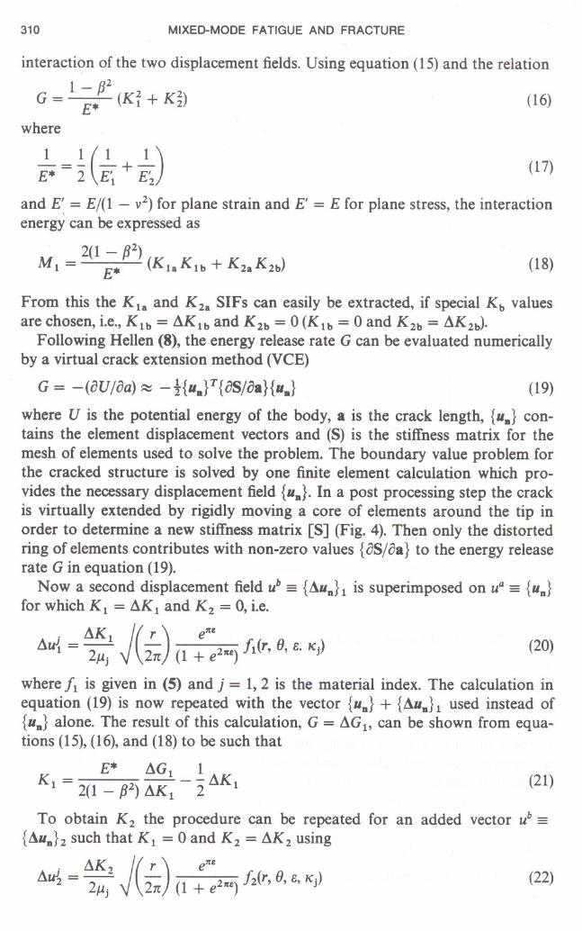
310 MIXED-MODE FATIGUE AND FRACTURE
(18)
interaction of the two displacement fields. Using equation (15) and the relation
1 ß2
G = E* (Ki + K~) (16)where
1 1(1 1)-=- -+- (17)E* 2 E' E'1 2
and g = E/(1 - v2) for plane strain and E' = E for plane stress, the interactionenergy can be expressed as
2(1 - ß2)M1 = r-* (KlaK1b + K2aK2b)
From this the K1a and K2a SIFs can easily be extracted, if special Kb valuesare chosen, i.e., K1b = AK1b and K2b = 0 (K1b = 0 and K2b = AK2b).
Following Hellen (8), the energy release rate G can be evaluated numericallyby a virtual crack extension method (VCE)
(19)
(22)
where U is the potential energy of the body, a is the crack length, {UD} contains the element displacement vectors and (S) is the stiffness matrix for themesh of elements used to solve the.problem. The boundary value problem forthe cracked structure is solved by one finite element calculation which provides the necessary displacement field {UD}' In a post processing step the crackis virtually extended by rigidly moving a core of elements around the tip inorder to determine a new stiffness matrix ES] (Fig. 4). Then only the distortedring of elements contributes with non-zero values {eS/ca} to the energy releaserate Gin equation (19).
Now a second displacement field ub = {AuD}1 is superimposed on ua = {UD}
for which K1 = AK1 and K2 = 0, i.e.
. AK 1 J( r ) e1t1!.Au{ = 2f.J.j 2n (1 + e21t1!.) /1(r, fJ, e. "j) (20)
where /1 is given in (5) and j = 1,2 is the material index. The calculation inequation (19) is now repeated with the vector {UD} + {AuD}1 used instead of{UD} alone. The result of this calculation, G = AG1, can be shown from equations (15), (16), and (18) to be such that
E* AG1 1
K1 = 2(1 _ ß2) AK1 - 2 AK1 (21)
To obtain K2 the procedure can be repeated for an added vector ub ={AUD}2 such that K1 = 0 and K2 = AK2 using
. AK 2 J( r ) e1t1!.Au~ = 2f.J.j 2n (1 + e21t1!.) /2(r, fJ, e, "j)

INTERFACE CRACKS IN DISSIMILAR MEDIA 311
rigid
distorted
Fig 4 A typical ring of elements around tbe crack tip to be distorted in the J calculatioDs
or alternatively using equation (16) to determine Kz. From these K1, Kz
values the aspired Kl,n SIFs can be determined using equatio~ (5). A moredetailed description of computing interfacial stress intensities cab be found inMatos et al. (5).
Calibrating the compact tension shear loading device for testing bimaterials
The geometry to be used for testing bimaterials is shown in Fig. 5. A similarcompact tension shear (CTS) loading device has been used· successfully byRichard (9) to measure the fracture toughness in homogeneous materials. Themode ratio is varied by chan ging the loading angle w. This angle can rangefrom - 90 to +90 degrees. For homogeneous materials pure mode I conditions are achieved when w = 0 degrees and pure mode 11 conditions whenw = +90 degrees.
For testing small bimaterial specimens having a low interface fracturetoughness, the CTS loading device must be modified for eliminating inherentmass moments. Depending on the material to be tested, the resulting momentmight cause SIFs which are elose to the critical Kc value of the bimaterial. Forthis reason the originalloading device is counterbalanced by additional compensation weights as shown in Fig. 5.
The finite element model used to solve the elastic boundary value problemis shown in Fig. 6. The model employs eight-noded quadrilateral plane mem-

312 MIXED-MODE FATIGUE AND FRACTURE
F
loadingangle c.J /
/
1) CTS loading device
2) CTS specimen
3) counterbalance unit
)
Fig 5 Modified crs loading device and specimen geometry
brane elements, with a square focused crack tip mesh. The loading device itselfdoes not need to be modelIed and can be simulated by the tabulated static/kinematic boundary conditions. These boundary conditions correspond to theloading angle Q) and are tabulated in Table 1 (9). Increasing crack lengthratios were simulated by moving the square focused crack tip mesh throughthe remaining structure. This procedure provides crack length ratios of
a/w = i/6 (i = 1, 2, 3, 4) (23)
The specimen has been calibrated systematically for a wide range ofmaterial combinations and crack length ratios according to the numerical procedure described in the previous section. Beside this variation we utilized acharacteristic bimaterial property by which most technically importantmaterial combinations can be approximately described through the relation

INTERFACE CRACKS IN DISSIMILAR MEDIA 313
x
Fig 6 Finite element model of tbe CTS specimen and its Ijding grip
ß = rx/4 (10) and are within the limits (Fig. 7)
o ~ rx ~ 0.6
rx/4 - 0.1 ~ ß ~ rx/4 + 0.1 (24)
The K calibration of the CTS geometry following equation (5) uses a representative stress magnitude of
FT=wt
(25)
where F is the applied load, w the specimen width, and t the specimen thickness. The calibration of the CTS specimen is reduced to determining ~ and t/J
for the interesting range of material combinations, crack length ratios, andloading angles.

314 MIXED-MODE FATIGUE AND FRACTURE
Table 1
Kinematie and statieboundaryeonditiollSaccording to (9) ror computing tbe crsgeometry using tbe finite element metbodKinematic boundary conditions
Q)
a a'bc
V,
V,VxV,
0°
0 - 0015°
0- 0030°
- 00045°
- 00060°
- 00075°
- 00090°
- 000
Static boundary conditions
-Q)d d' ef
F,
F,FxF,
0°
0.50*F -O.OO*F0.50*F15°
0.22*F--0.26*F0.74*F30°
--0.07*F-0.50*F0.93*F45°
--0.35*F-O.71*Fl.06*F60°
--0.62*F-0.87*F1.12*F75°
--0.84*F-0.97*Fl.09*F90°
--l.OO*F-l.OO*Fl.OO*F
0.2
0.1
0.0
-0.1
-0.2
0.0
/J=a/4+0.1
lass/epoxy
1.0
Fig 7 Distribution of typical material combinatiollS in tbe a.-ß diagram according to (10)

6
INTERFACE CRACKS IN DISSIMILAR MEDIA
a/w=4/6 ß=a./4
315
5
4
2
1
o I-90 -60 -30 o 30 60 90
(,,)
Fig 8 crs calibration functions, Yk = Yk(alw, w, ~ fJ)
The dependence of ~ and '" on cx, ß = cx/4, a/w and w is shown in "g. 8 andFig. 9(a)-(d). However, similar results have been obtained for different ß valuesaccording to equation (24). Obviously the computed ~ and '" values are nolonger symmetrie with respect to the sign of w, except for the homogeneouscase cx = ß = o. There is a significant difference relative to the resulting ~ and'" values whether the applied load is positively (w > 0 degrees) or negatively(w < 0 degrees) introduced. In general we ascertain that
~(w > 0 degrees) =1=Yiw < 0 degrees)
and
(26)
I'" I(w > 0 degrees) =1=I'" I(w < 0 degrees)
holds for systems with cx, ß =1=o.From Fig. 8 we also obtain an increasing crack length effect on this ~
asymmetry: a crack length ratio a/w = 4/6 needs a K calibration of Yk= 2.7

316 MIXED-MODE FATIGUE AND FRACTURE
100
1Oll
15
'7G
46
46
Ul
15" "-15
-15
-46
-45
-15
-'7G
-10ll
-10ll-80
-eo-300308080 -80-eo-3003080
c.l ( b )c.l
( a )
1Oll
1Oll
15
'7G
46
46
15
15
" "-15
-1l!
-46
-46
-15-10ll I
IIIIII -1011
-80
-80-3003080110 -80-eo-SO030
( C )
c.l c.l
( d )Fig 9
CTS phase angles, '" = tjI(alw, co, oe, fJ)
for w = - 60 degrees whilst w = +60 degrees must be corrected with ~ = 3.3,considering a = 0.6.
The local phase angle ljJ (Fig. 9) is affected by changes in the crack lengthratio. Short cracks with a/w = 1/6 produce a phase angle of IljJI (w = +90degrees) ~ 90 degrees independent of the chosen a value. Therefore, mode 11fracture tests result in mode 11 crack tip conditions, which are unaffected bythe elastic mismatch if the crack length ratio is about a/w = 1/6. The a dependence becomes more evident when changing towards mode I fracture tests: ata loading angle w = 0 degree, short cracks of a/w = 1/6 experience mixedmode conditions with a small mode 11contribution resulting in smallljJ valuesof less than 10 degrees. Similar results were found by ü'Dowd et al. (11) forbend bar geometries.

INTERFACE CRACKS IN DISSIMILAR MEDIA 317
The func~ional effect of the elastic mismatch a and ß on the phase l/J issomewhat different when passing over to crack length ratios larger thana/w> 1/6: increasing a values produce an increasing phase shift towardshigher l/J values along the full range of loading angles. This entails negative K,values (l/J > 90 degrees) when remotely loading in negative mode II direction(w = - 90 degrees), i.e., the crack surfaces experience compressive stresses.Positive w values always lead to a crack opening mode, independent of theelastic mismatch and crack length ratio.
Conclusions
The near tip stress field of an interface crack was investigated in order todetermine a suitable criterion for the interface fracture of bimaterials. The presented results predict a strong influence of the elastic mismatch on the onset ofcrack growth as well as on the preferred kinking angles for cracks deviatingfrom the interface, on the condition that interfacial stress intensity factors canbe taken as crack controlling parameters. There is strong evidence that carefulattention must be paid to the sign of Ku values when examining bimaterialswith e =1= O.The applicability of the elaborated fracture criterion for bimaterialswill be verified by future mixed-mode experiments using a modified CTSloading device.
The preliminary studies on calibrating this CTS specimen provide the basisfor these experiments. The computation of local mode ratio was performedusing a modified virtual crack extension technique. Asymmetrie trends in thecalibration functions Yi.: and the phase angles l/J were found with respect to thesign of the loading angle w. Increasing crack length ratios intensifies the influence of elastic misfit properties on Yi.: and l/J.
It can be conc1uded that stress intensity factors and phase angles of the t.TSbimaterial specimen have been presented for the first time in a systemJticmanner as a function of crack length, elastic mismatch, and loading state. Theexact knowledge of these SIFs is important for all systems with elastic misfit.In the framework of linear eIasticity the single mode SIFs Kj (i = I, 11)may besuperimposed on stress intensity factors due to thermal stresses (12) in orderto obtain effective SIFs acting in thermally pre-stressed bimaterials.
Acknowledgements
This work was supported by the Deutsche Forschungsgemeinschaft (projectEL 53/13-1); their support is gratefully acknowledged. Many thanks are alsodue to Dr F. G. Buchholz for his helpful discussions.
Appendix
Angular functions for the near crack tip stress field of an interface crack lyingbetween two isotropie materials (Rice, Suo, Wang 1990)

318 MIXED-MODE FATIGUE AND FRACTURE
Mode! angular functions
I sinh e(n - 8) (38) e-e(1t-9) (8)L = ------cos - +---cos -
rr cosh (ne) 2 cosh (ne) 2 .
x {I + Sin2(~) + 6 sin (lIl}
sinh e(n - 8) (38) e-e(1t-9) (8){ (8) }L~9 = " , cos "2 + cosh (ne) cos 2 cos2 2 - e sin (8)
sinh e(n - 8) (38) e-e(1t-9) (8){ (8) }L~9 = u _ L ,_ ~, sin "2 + cosh (ne) sin 2 cos2 2 - e sin (8)
Mode I I angular functions
cosh e(n - 8) (38) e-e(1t-9) (8){ (8) }L~~= cosh (ne) sin "2 - cosh (ne) sin 2 1 + cos2 2 - e sin (8)
cosh e(n - 8) (38) e-e(1C-9) (8){ (8) }L~9 = ~u1~ " sin "2 - cosh (ne) sin 2 sin2 2 + e sin (8)
cosh e(n - 8) (38) e-Il(1t-9) (8){ (8) }L~~= u ~1~, , COS "2 + cosh (ne) cos 2 sin2 2 + e sin (8)
References
(1) ERDOGAN, F. and SIH, G. C. (1963) On the crack extension in plates under plane loadingand transverse shear, J. Basic Engng, 85,519-525.
(2) RICE, J. R., SUO, Z., and WANG, J.-S. (1990) Mechanics and thermodynamics of brittleinterfacial failure in bimaterial systems, Acta Scripta Met., 4, 269-294.
(3) RICE, J. R. (1988) Elastic fracture mechanics concepts for interfacial cracks, J. Appl. Mech.,
55, 98-103. "(4) DUNDURS, J. (1969) Edge-bonded dissimilar orthogonal elastic wedges under normli\ andshear loading, J. Appl. Mech. 36, 650-652.
(5) MATOS, P. P., McMEEKING, R. M., CHARALAMBIDES, P. G., and DRORY, M. D.(1989) A method for calculating stress intensities in bimaterial fracture, Int. J. Fracture 40,235-254.
(6) RICE, J. R. (1968) A path independent and approximate analysis of strain concentration bynotches and cracks, J. Appl. Mech., 35, 379-386.
(7) CHEN, F. H. K. and SHIELD, R. T. (1977) Conservation laws in elasticity of the J integraltype, ZeitschriftJür angewandte Mathematik und Mechanik, 28, 1-22.
(8) HELLEN, T. K. (1975) On the method of virtual crack extensions, Int. J. Num. MethodsEngng,9,187-207.
(9) RICHARD, H. A. (1985) Bruchvorhersagen bei überlagerter Normal- und Schubbeanspruchung von Rissen, VDI-Forschungsheft, 631, VDI-Verlag, Düsseldorf.
(10) SUGA, T., ELSSNER, G., and SCHMAUDER, S. (1988) Composite parameters and mechanical compatibility of material joints, J. Composite Mater., 22, 917-934.
(11) O'DOWD, N. P., SHIH, C. F., and STOUT, M. G. (1992) Test geometries for measuringinterfacial fracture toughness, Int. J. Solids Structures, 5, 571-589.
(12) MEYER, M. and SCHMAUDER, S. (1992) Thermal stress intensity factors of interfacecracks in bimaterials, Int. J. Fracture, submitted for publication.
Mixed-Mode Fatigue and Fracture
Edited by
H. P. Rossmanith
and
K. J. Miller
ESIS Publication 14
Papers presented at the International Conference onMixed-Mode Fracture and Fatigue held at the TechnicalUniversity of Vienna, Austria.
~SISEuropean Structural Integrity Society
Mechanical Engineering Publications LimitedLONDON
First published 1993
This publication is copyright under the Berne Convention and the International Copyright Convention. All rights reserved. Apart from any fair dealingfor the purpose of private study, research, criticism or review, as permittedunder the Copyright, Designs and Patents Act, 1988, no part may be reproduced, stored in a retrieval system, or transmitted in any form or by anymeans, electronic, electrical, chemieal, mechanical, photocopying, recording orotherwise, without the prior permission of the copyright owners. Reprographiereproduction is permitted only in accordance with the terms of licences issuedby the Copyright Licensing Agency, 90 Tottenham Court Road, London·W1P9HE. Unlicensed multiple copying of the contents of this publication is illegal.Inquiries should be addressed to: The Managing Editor, Mechanical Engineering Publications Limited, Northgate Avenue, Bury St Edmunds, Suffolk,IP326BW.
Authorization to photocopy items for personal or internal use, is granted bythe Institution of Mechanical Engineers for libraries and other users registeredin the Uni ted States with the Copyright Clearance Center (CCC), providedthat the fee of $0.50 per page is paid direct to CCC, 21 Congress Street, Salem,Ma 01970, USA. This authorization does not extend to other kinds of copyingsuch as copying for general distribution for advertising or promotional purposes, for creating new collective works, or for resale (085298 $0.00 + .50).
© 1993 European Structural Integrity Society
ISBN 0 85298 845 1
A CIP catalogue record for this book is available from the British Library.
Typeset by Santype International Limited, Salisbury