Mitigation of Power Quality Issues using UPQC with STF-SRF ...
12
JOURNAL OF ELECTRICAL AND ELECTRONIC SYSTEMS RESEARCH 105 Abstract— A three-phase three-wire of Unified Power Quality Conditioner (UPQC) is used to compensate for the power quality issues that exist in the point of common coupling (PCC) on the microgrid (MG) of the power system and the harmonics penetrated by the non-linear loads. This paper presents an amalgamation of a self-tuning filter (STF) with synchronous reference framework (SRF) of direct-quadrature-zero (dq0) fundamental based on UPQC to enhance power quality at the PCC under adverse voltage source condition (unbalanced and distorted source voltage). The modified SRF technique integrated the self- tuning filter (STF) with the unit vector generator (UVG) technique for designing the control phase synchronization algorithm of UPQC. Therefore, a phase-locked loop (PLL) necessity is omitted. The STF-UVG is used to produce the synchronization phases reference which can lead to UPQC controller generated reference current and voltage in phase with the operating power system. The suggested STF-SRF technique is compared with the traditional SRF technique by considering several case scenarios of source voltage in MATLAB-Simulink software are discussed in detail. Index Terms— Power Quality Issues, Unified Power Quality Conditioner (UPQC), Self-Tuning Filter (STF), Synchronization Phases, Phase-Locked Loop (PLL), Microgrid (MG). I. INTRODUCTION HE booming global energy demand is the main reason for increased fossil fuel burning and increased greenhouse gas emissions. Many researchers are working to find ways to substitute traditional fossil fuels and reduce environmental issues by encouraging the renewable generation sector. For this rationale, in recent years, the implementation and unification of renewable energy generation (REG) into the existing power system has grown significantly. The amalgamation of existing distribution generation (DG) with energy storage systems (ESS) is also needed due to REG characteristics of high environment- dependency, instability, and generate a small amount of power during peak time [1][2]. Therefore, MG's concept is developed with composed of REG, ESS, DG, and load cluster that share the same PCC that performs as a single grid as shown in Fig. 1. However, one of the most relevant technical challenges with functioning and handling MG systems concerns power quality issues [3]. Due to the structure, operating model, and REG performance in MG, these challenges are a significant concern in the MG system. Many of the power quality issues caused by DG's high penetration include current harmonics, voltage harmonics, voltage swell or sag, fluctuation, unbalance, protective system breakdown, electrical equipment overloading, and failure [4]. This matter is caused by MG sources entirely dependent on power electronic converters, which may also extend the presence of power electronic interfaces in an existing distribution network [5]. One of the most powerful solutions to enhance the power quality is to utilize the UPQC on the PCC of the MG [6]. It is a custom power device that can mitigate the power quality issues on both sides of voltage and current [7]. H. Akagi first introduced the UPQC in 1995 as one of the most innovative technologies that Mitigation of Power Quality Issues using UPQC with STF-SRF Technique Under Adverse Voltage Source Condition Muhammad Alif Mansor, Muhammad Murtadha Othman, Ismail Musirin and Siti Zaliha Mohammad Noor. T Fig. 1. Structure diagram of MG. This manuscript is submitted on 21 st September 2020 and accepted on 4 th March 2021. Muhammad Alid Mansor, Muhammad Murtadha Othman, Ismail Musirin and Siti Zaliha Mohammad Noor are with the School of Electrical Engineering, College of Engineering, Universiti Teknologi MARA, 40450 Shah Alam, Selangor (e-mail: [email protected], [email protected],[email protected], [email protected]) 1985-5389/© 2021 The Authors. Published by UiTM Press. This is an open access article under the CC BY-NC-ND license (http://creativecommons.org /licenses/by-nc-nd/4.0/). doi.org/10.24191/jeesr.v19i1.014
Transcript of Mitigation of Power Quality Issues using UPQC with STF-SRF ...
JOURNAL OF ELECTRICAL AND ELECTRONIC SYSTEMS RESEARCH
105
Abstract— A three-phase three-wire of Unified Power Quality
Conditioner (UPQC) is used to compensate for the power quality issues that exist in the point of common coupling (PCC) on the microgrid (MG) of the power system and the harmonics penetrated by the non-linear loads. This paper presents an amalgamation of a self-tuning filter (STF) with synchronous reference framework (SRF) of direct-quadrature-zero (dq0) fundamental based on UPQC to enhance power quality at the PCC under adverse voltage source condition (unbalanced and distorted source voltage). The modified SRF technique integrated the self-tuning filter (STF) with the unit vector generator (UVG) technique for designing the control phase synchronization algorithm of UPQC. Therefore, a phase-locked loop (PLL) necessity is omitted. The STF-UVG is used to produce the synchronization phases reference which can lead to UPQC controller generated reference current and voltage in phase with the operating power system. The suggested STF-SRF technique is compared with the traditional SRF technique by considering several case scenarios of source voltage in MATLAB-Simulink software are discussed in detail.
Index Terms— Power Quality Issues, Unified Power Quality Conditioner (UPQC), Self-Tuning Filter (STF), Synchronization Phases, Phase-Locked Loop (PLL), Microgrid (MG).
I. INTRODUCTION HE booming global energy demand is the main reason for increased fossil fuel burning and increased greenhouse gas
emissions. Many researchers are working to find ways to substitute traditional fossil fuels and reduce environmental issues by encouraging the renewable generation sector. For this rationale, in recent years, the implementation and unification of renewable energy generation (REG) into the existing power system has grown significantly. The amalgamation of existing distribution generation (DG) with energy storage systems (ESS) is also needed due to REG characteristics of high environment-
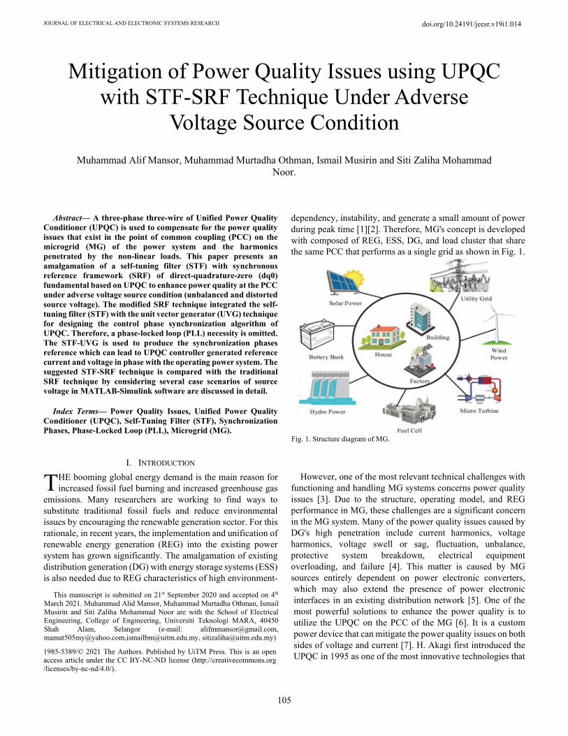
dependency, instability, and generate a small amount of power during peak time [1][2]. Therefore, MG's concept is developed with composed of REG, ESS, DG, and load cluster that share the same PCC that performs as a single grid as shown in Fig. 1.
However, one of the most relevant technical challenges with functioning and handling MG systems concerns power quality issues [3]. Due to the structure, operating model, and REG performance in MG, these challenges are a significant concern in the MG system. Many of the power quality issues caused by DG's high penetration include current harmonics, voltage harmonics, voltage swell or sag, fluctuation, unbalance, protective system breakdown, electrical equipment overloading, and failure [4]. This matter is caused by MG sources entirely dependent on power electronic converters, which may also extend the presence of power electronic interfaces in an existing distribution network [5]. One of the most powerful solutions to enhance the power quality is to utilize the UPQC on the PCC of the MG [6]. It is a custom power device that can mitigate the power quality issues on both sides of voltage and current [7]. H. Akagi first introduced the UPQC in 1995 as one of the most innovative technologies that
Mitigation of Power Quality Issues using UPQC with STF-SRF Technique Under Adverse
Voltage Source Condition Muhammad Alif Mansor, Muhammad Murtadha Othman, Ismail Musirin and Siti Zaliha Mohammad
Noor.
T
Fig. 1. Structure diagram of MG.
This manuscript is submitted on 21st September 2020 and accepted on 4th
March 2021. Muhammad Alid Mansor, Muhammad Murtadha Othman, Ismail Musirin and Siti Zaliha Mohammad Noor are with the School of Electrical Engineering, College of Engineering, Universiti Teknologi MARA, 40450 Shah Alam, Selangor (e-mail: [email protected], [email protected],[email protected], [email protected])
1985-5389/© 2021 The Authors. Published by UiTM Press. This is an open access article under the CC BY-NC-ND license (http://creativecommons.org /licenses/by-nc-nd/4.0/).
doi.org/10.24191/jeesr.v19i1.014
JOURNAL OF ELECTRICAL AND ELECTRONIC SYSTEMS RESEARCH, VOL. 19 OCT 2021
106
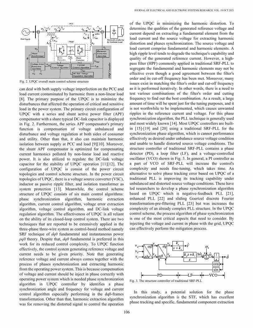
can deal with both supply voltage imperfection on the PCC and load current contaminated by harmonic from a non-linear load [8]. The primary purpose of the UPQC is to minimize the disturbances that affected the operation of critical and sensitive load in the power system. The primary circuit configuration of UPQC with a series and shunt active power filter (APF) compensator with a share typical DC-link capacitor is displayed in Fig. 2. Furthermore, the series APF compensator's primary function is compensation of voltage unbalanced and disturbance and voltage regulation at both sides of consumer and utility. Other than that, it also can maintain harmonic isolation between supply at PCC and load [9][10]. Moreover, the shunt APF compensator is optimized for compensating current harmonics polluted by non-linear load and reactive power. It is also utilized to regulate the DC-link voltage capacitor for the stability of UPQC operation [11][12]. The configuration of UPQC is consist of the power circuit topologies and control scheme structure. In the power circuit topologies of UPQC, there is a voltage source converter (VSC), inductor as passive ripple filter, and isolation transformer as system protection [13]. Meanwhile, the control scheme structure of UPQC consists of six main control algorithms: phase synchronization algorithm, harmonic extraction algorithm, current control algorithm, voltage error extraction algorithm, voltage control algorithm, and DC-link voltage regulation algorithm. The effectiveness of UPQC is all reliant on the ability of its closed-loop control system. There are two techniques that are reported to be extensively applied in the three-phase three-wire system as control-based method namely SRF technique of dq0 fundamental and instantaneous power pq0 theory. Despite that, dq0 fundamental is preferred in this work for its reduced control complexity. To UPQC function effectively, the control system generating reference voltage and current needs to be given priority. Note that generating reference voltage and current always comes together with the process of phases synchronization and extracting harmonic from the operating power system. This is because compensation of voltage and current should be inject in phase correctly with operating power system which is needed phase synchronization algorithm in UPQC controller by identifies a phase synchronization angle and frequency for voltage and current control algorithm especially performing in the dq0-frames transformation. Other than that, harmonic extraction algorithm was for removing the distorted signal to control the operation
of the UPQC in minimizing the harmonic distortion. To determine the qualities of the generated reference voltage and current depend on extracting a fundamental element from the load current and the source voltage for extracting harmonic distortion and phases synchronization. The source voltage and load current comprise fundamental and harmonic elements. A high ripple level tends to degrade the technique's capability and quality of the generated reference current. However, a high-pass filter (HPF) commonly applied in traditional SRF-PLL to segregate the fundamental and harmonic elements may not be effective even though a good agreement between the filter's order and its cut-off frequency has been met. Moreover, many issues exist in matching the filter's order and cut-off frequency as it is performed iteratively. In other words, there is a need to test various combinations of the filter's order and cutting frequency to find out the best combination. As a result, a large amount of time will be spent just for the tuning purposes, and it is not worthwhile to be implemented, which causes unwanted ripples in the reference current and voltage. For this phase synchronization algorithm, the PLL technique is generally used and most widely known [14]. Most UPQC controllers are built-in [15]-[19] and [20] using a traditional SRF-PLL for the synchronization phase algorithm, which is cannot performance effectively as desired under unbalance source voltage condition and unable to handle distorted source voltage conditions. The structure controller of traditional SRF-PLL contains a phase detector (PD), a loop filter (LF), and a voltage-controlled oscillator (VCO) shown in Fig. 3. In general, a PI controller as a part of VCO of SRF-PLL will increase the control's complexity and needs fine-tuning, which takes time. An alternative to solve phase tracking error based on UPQC of a traditional PLL is improving its tracking capability under unbalanced and distorted source voltage conditions. These have led researchers to develop a phase synchronization algorithm based on UPQC which is negative-feedback PLL [21], enhanced PLL [22] and sliding Goertzel discrete Fourier transformation-pre-filtering PLL [23] but was increases the complexity of an already complex PLL structure. In the UPQC control scheme, the process algorithm of phase synchronization is one of the most critical aspects that need to consider. By injecting the voltage and current in phase with the grid, UPQC can effectively perform the mitigation process.
In this study, a potential solution for the phase
synchronization algorithm is the STF, which has excellent phase tracking and specific, fundamental component extraction
Fig. 2. UPQC overall main control scheme structure
Fig. 3. The structure controller of traditional SRF-PLL

Mansor et al.: Mitigation of Power Quality Issues using UPQC with STF-SRF Technique Under Adverse Voltage Source Condition
107
capabilities for dealing with adverse source voltage conditions. To remove the complexity working block VCO of PLL, the straightforward phase synchronization of UVG is utilized to generate unit vectors consisting of sine and cosine functions. Furthermore, the modified traditional SRF technique with STF is utilized to extract harmonic elements to generate reference current for UPQC. The suggested STF-SRF technique based on UPQC is compared with the traditional SRF technique based on UPQC. Validation of this study to support the STF-SRF technique based on UPQC was done by considering several case source voltage scenarios in MATLAB-Simulink software is discussed in detail.
II. PROPOSED STF-SRF TECHNIQUE BASED ON UPQC The main controller of UPQC is the series and shunt APF
compensator controller, which includes the synchronization phase algorithm method for both controllers. The series APF compensator controller insulates the critical load from the source voltage of power quality problems (grid side) by compensating appropriate voltage in phase with the grid voltage. The shunt APF compensator is optimized for compensating current harmonics polluted by non-linear load and reactive power. It also is utilized for regulating the DC-link voltage capacitor for the stability of UPQC operation. UPQC is a control-based method designed to integrate STF with the SRF technique of dq0-fundamental to perform effectively under unbalanced and distorted source voltage conditions. Generally, the present STF-SRF technique based on UPQC generates reference voltage and current in the same concept as a traditional SRF technique. Nevertheless, the two improvements are made to enhance further the performance of UPQC, which utilizes the straightforward phase synchronization of UVG with STF (STF-UVG) for suppressing the negative sequence of the source voltage. Other than that, STF also utilizes to extract the harmonic element for generating reference current in the shunt APF compensator controller.
A. Synchronization Phase Algorithm Method The suggested STF-UVG utilizes the measured source
voltage at the PCC to generate the synchronization phase for the STF-SRF technique based on UPQC to compensate in-phase with the grid supply shown in Fig. 4. The Clarke transformation matrix is utilized to transform three-phase source voltage from abc-domain to αβ0-domain is demonstrated in (1).
�𝑈𝑈𝛼𝛼𝑈𝑈𝛽𝛽𝑈𝑈0� = �
23
⎣⎢⎢⎢⎢⎡1 −
12
−12
0√32
−√32
12
12
12 ⎦
⎥⎥⎥⎥⎤
�𝑈𝑈𝑎𝑎𝑈𝑈𝑏𝑏𝑈𝑈𝑐𝑐� (1)
By considering only two phases in the αβ-domain, the distorted source voltage can be categories into a fundamental and harmonic element. Therefore, the fundamental (fund) element state as a 𝑉𝑉𝑠𝑠,𝛼𝛼𝛽𝛽(𝑓𝑓𝑓𝑓𝑓𝑓𝑓𝑓) and the harmonic (har) element state as 𝑉𝑉𝑠𝑠,𝛼𝛼𝛽𝛽(ℎ𝑎𝑎𝑎𝑎) in 𝛼𝛼𝛼𝛼-domain. It is required the fundamental element only to produce phase reference. By using the STF, the fundamental element can split from the distorted source voltage signal. Thus, the STF can eliminate all the negative sequences existing in the distorted voltage signal and improve the synchronization phase's extraction quality. The Laplace transformation is executed, and a typical STF transfer function is shown in (2)
�𝑈𝑈𝛼𝛼 (𝑓𝑓𝑓𝑓𝑓𝑓𝑓𝑓)(𝑠𝑠)𝑈𝑈𝛽𝛽 (𝑓𝑓𝑓𝑓𝑓𝑓𝑓𝑓)(𝑠𝑠)� =
𝐾𝐾1𝑠𝑠�𝑈𝑈𝛼𝛼(𝑠𝑠) − 𝑈𝑈𝛼𝛼 (𝑓𝑓𝑓𝑓𝑓𝑓𝑓𝑓)(𝑠𝑠) 𝑈𝑈𝛽𝛽(𝑠𝑠) − 𝑈𝑈𝛽𝛽 (𝑓𝑓𝑓𝑓𝑓𝑓𝑓𝑓)(𝑠𝑠)�
+ 2𝜋𝜋𝑓𝑓𝑐𝑐1𝑠𝑠
�−𝑈𝑈𝛽𝛽 (𝑓𝑓𝑓𝑓𝑓𝑓𝑓𝑓)(𝑠𝑠)𝑈𝑈𝛼𝛼 (𝑓𝑓𝑓𝑓𝑓𝑓𝑓𝑓)(𝑠𝑠) �
(2)
Here, K1 indicates the constant gain parameter, and fc1 indicates the power system's cut-off frequency. In this study, the rating is determined 20 for K1 and 50 Hz for fc1. In (3), demonstrated the straightforward phase synchronization of UVG, which applying the 𝑉𝑉𝑠𝑠,𝛼𝛼(𝑓𝑓𝑓𝑓𝑓𝑓𝑓𝑓) and 𝑉𝑉𝑠𝑠,𝛽𝛽 (𝑓𝑓𝑓𝑓𝑓𝑓𝑓𝑓) to obtain synchronization phases reference in term of sin(𝜔𝜔𝜔𝜔) and cos(𝜔𝜔𝜔𝜔). The action of a traditional VCO of PLL structure can be omitted, which can reduce control complexity.
�sin(𝜔𝜔𝜔𝜔)cos(𝜔𝜔𝜔𝜔)�
= 1
�(𝑉𝑉𝑆𝑆𝛼𝛼 (𝑓𝑓𝑓𝑓𝑓𝑓𝑓𝑓) )2 + (𝑉𝑉𝑆𝑆𝛼𝛼 (𝑓𝑓𝑓𝑓𝑓𝑓𝑓𝑓) )2 �𝑉𝑉𝑆𝑆𝛼𝛼 (𝑓𝑓𝑓𝑓𝑓𝑓𝑓𝑓)
−𝑉𝑉𝑆𝑆𝛼𝛼 (𝑓𝑓𝑓𝑓𝑓𝑓𝑓𝑓)� (3)
Fig. 5. Series APF Compensator control scheme structure
Fig. 4. Synchronization Phase control scheme structure
STF-UVG
(2) & (3)

JOURNAL OF ELECTRICAL AND ELECTRONIC SYSTEMS RESEARCH, VOL. 19 OCT 2021
108
B. Series APF Compensator Controller The control scheme structure of series APF compensator
based on SRF technique implement the following sequence of transformation (abc-αβ0-dq0-αβ0-abc) displayed in Fig. 5. Firstly, in (4), is the three-phase reference voltage signal, 𝑉𝑉𝑎𝑎𝑟𝑟𝑓𝑓,𝑎𝑎𝑏𝑏𝑐𝑐
∗ in 𝑎𝑎𝑎𝑎𝑎𝑎-domain. Here, the parameter of maximum peak voltage magnitude, 𝑉𝑉𝑚𝑚,𝑚𝑚𝑎𝑎𝑚𝑚−𝑝𝑝𝑟𝑟𝑎𝑎𝑝𝑝 is acquired from a peak amplitude of the actual grid source voltage. Next, the three-phase reference voltage signal converts from abc-domain to αβ0-domain using the Clarke transformation matrix (1). Secondly, the resulted synchronization phases reference STF-UVG in term of sin(𝜔𝜔𝜔𝜔) and cos(𝜔𝜔𝜔𝜔) obtained in (3) is utilized for creating a reference axis in the 𝑓𝑓𝑑𝑑-domain of the park transformation matrix. It is used to a covert reference voltage signal in the 𝑓𝑓𝑑𝑑-domain id demonstrated in (5). Furthermore, the three-phase load voltage, 𝑉𝑉𝐿𝐿,𝛼𝛼𝑏𝑏𝑐𝑐 and the three-phase supply voltage, 𝑉𝑉𝑠𝑠,𝛼𝛼𝑏𝑏𝑐𝑐 also, utilizing the Clarke-Park matrix to transform from abc-domain into 𝑓𝑓𝑑𝑑-domain is demonstrated in (1) and (5). In the series APF compensator, a voltage error extraction algorithm method is using a comparison technique of the load voltage, 𝑉𝑉𝐿𝐿,𝑓𝑓𝑑𝑑 and source voltage, 𝑉𝑉𝑠𝑠,𝑓𝑓𝑑𝑑 at PCC, both in the 𝑓𝑓𝑑𝑑-domain to result in real voltage error. Next, a real reference voltage is obtained by differentiating between the reference voltage signal, 𝑉𝑉𝑎𝑎𝑟𝑟𝑓𝑓,𝑓𝑓𝑑𝑑
∗ and supply voltage, 𝑉𝑉𝑠𝑠,𝑓𝑓𝑑𝑑 in the 𝑓𝑓𝑑𝑑-domain. Thus, the compensation reference voltage, 𝑉𝑉𝑆𝑆𝑆𝑆,𝑓𝑓𝑑𝑑
∗ acquired by comparing a real reference voltage and a real voltage error is shown in (6).
�𝑉𝑉𝑎𝑎𝑟𝑟𝑓𝑓𝑎𝑎
∗
𝑉𝑉𝑎𝑎𝑟𝑟𝑓𝑓𝑏𝑏∗
𝑉𝑉𝑎𝑎𝑟𝑟𝑓𝑓𝑐𝑐∗� = 𝑉𝑉𝑚𝑚𝑚𝑚𝑎𝑎𝑚𝑚−𝑝𝑝𝑝𝑝𝑎𝑎𝑝𝑝
⎣⎢⎢⎢⎡
sin(𝜔𝜔𝜔𝜔)
sin(𝜔𝜔𝜔𝜔 − 2𝜋𝜋3
)
sin(𝜔𝜔𝜔𝜔 + 2𝜋𝜋3
)⎦⎥⎥⎥⎤
(4)
�𝑈𝑈𝑓𝑓𝑈𝑈𝑑𝑑� = � cos(𝜔𝜔𝜔𝜔) sin(𝜔𝜔𝜔𝜔)
− sin(𝜔𝜔𝜔𝜔) cos(𝜔𝜔𝜔𝜔)� �𝑈𝑈𝛼𝛼𝑈𝑈𝛽𝛽� (5)
𝑉𝑉𝑆𝑆𝑆𝑆𝑑𝑑𝑑𝑑∗ = �𝑉𝑉𝑎𝑎𝑟𝑟𝑓𝑓𝑑𝑑𝑑𝑑
∗−𝑉𝑉𝑆𝑆𝑑𝑑𝑑𝑑� − (𝑉𝑉𝐿𝐿𝑑𝑑𝑑𝑑−𝑉𝑉𝑆𝑆𝑑𝑑𝑑𝑑) (6)
Lastly, the equation (7) and (8) is used to transform from 𝑓𝑓𝑑𝑑-domain to 𝑎𝑎𝑎𝑎𝑎𝑎-domain of the compensation reference voltage, 𝑉𝑉𝑆𝑆𝑆𝑆,𝑓𝑓𝑑𝑑
∗. To produce appropriate gating pulses for the series VSC, the compensation reference voltage series compensator, 𝑉𝑉𝑆𝑆𝑆𝑆,𝑎𝑎𝑏𝑏𝑐𝑐
∗ is using a pulse width modulation (PWM) as a voltage control algorithm method.
�𝑈𝑈𝛼𝛼𝑈𝑈𝛽𝛽� = � sin(𝜔𝜔𝜔𝜔) cos(𝜔𝜔𝜔𝜔)
− cos(𝜔𝜔𝜔𝜔) sin(𝜔𝜔𝜔𝜔)� �𝑈𝑈𝑓𝑓𝑈𝑈𝑑𝑑� (7)
�𝑈𝑈𝑎𝑎𝑈𝑈𝑏𝑏𝑈𝑈𝑐𝑐� = �
23
⎣⎢⎢⎢⎡
1 0
−12
√32
−12
−√32 ⎦⎥⎥⎥⎤
�𝑈𝑈𝛼𝛼𝑈𝑈𝛽𝛽� (8)
C. Shunt APF Compensator Controller Next, the control scheme structure of the shunt APF
compensator is based on the SRF technique implement the following sequence of transformation (abc-αβ0-dq0-αβ0-abc) displayed in Fig. 6. The suggested STF is used for load current harmonic extraction in the shunt APF compensator controller. Firstly, the three-phase load current is converted from 𝑎𝑎𝑎𝑎𝑎𝑎 domain to 𝛼𝛼𝛼𝛼0-domain using Clarke-matrix (1). In 𝛼𝛼𝛼𝛼0-domain, it consists of a fundamental and harmonic element. Therefore, the fundamental (fund) element state as a 𝑖𝑖𝐿𝐿,𝛼𝛼𝛽𝛽 (𝑓𝑓𝑓𝑓𝑓𝑓𝑓𝑓) and the harmonic (har) element state as 𝑖𝑖𝐿𝐿,𝛼𝛼𝛽𝛽 (ℎ𝑎𝑎𝑎𝑎)in 𝛼𝛼𝛼𝛼-domain. The extraction of a fundamental element, 𝑖𝑖𝐿𝐿,𝛼𝛼𝛽𝛽 (𝑓𝑓𝑓𝑓𝑓𝑓𝑓𝑓) is utilizing the STF transfer function shown in (2). Here, K2 indicates the constant gain parameter, and fc2 indicates the power system's cut-off frequency. In this study, the rating is determined 20 for K2 and 50 Hz for fc2. The harmonic element, 𝑖𝑖𝐿𝐿,𝛼𝛼𝛽𝛽 (ℎ𝑎𝑎𝑎𝑎) is obtained after removing the fundamental element from the distorted load current as the harmonic extraction algorithm method is shown in (9). Thus, the harmonic element is extracted indirectly. Secondly, the transformation in 𝑓𝑓-domain is expressed in (10) is used the synchronization phase reference of STF-UVG in term of sin(𝜔𝜔𝜔𝜔) and cos(𝜔𝜔𝜔𝜔) obtained in (3) and load current of a harmonic element in (9). For transformation in 𝑑𝑑-domain, the original load current and the synchronization phase reference is utilized shown in (11). Moreover, the DC-link voltage regulation algorithm method is to stabilization the DC-link voltage capacitor obtained by calculating the appropriate 𝑖𝑖𝑟𝑟𝑎𝑎𝑎𝑎𝑒𝑒𝑎𝑎,𝑓𝑓𝑐𝑐. It is measured by minimizing the error acquired between total instantaneous DC-link voltage and reference DC-link voltage 𝑉𝑉𝑓𝑓𝑐𝑐,𝑎𝑎𝑟𝑟𝑓𝑓 with a PI controller. In this study, the value of proportional gain is set as 0.3, and integral gains are set as 2 of the PI controllers. Lastly, the equation (7) and (8) is used to transform from 𝑓𝑓𝑑𝑑-domain to 𝑎𝑎𝑎𝑎𝑎𝑎-domain of compensation reference current, 𝑖𝑖𝑆𝑆𝑆𝑆,𝑎𝑎𝑏𝑏𝑐𝑐 . The compensation reference voltage current is compared with measured compensation current in a hysteresis current controller algorithm method to produce appropriate gating pulses for the shunt VSC.
�𝑖𝑖𝐿𝐿𝛼𝛼 (ℎ𝑎𝑎𝑎𝑎)
𝑖𝑖𝐿𝐿𝛽𝛽 (ℎ𝑎𝑎𝑎𝑎)� = �
𝑖𝑖𝐿𝐿𝛼𝛼 − 𝑖𝑖𝐿𝐿𝛼𝛼 (𝑓𝑓𝑓𝑓𝑓𝑓𝑑𝑑) 𝑖𝑖𝐿𝐿𝛽𝛽 − 𝑖𝑖𝐿𝐿 𝛽𝛽 (𝑓𝑓𝑓𝑓𝑓𝑓𝑑𝑑)
� (9)
Fig. 6. Shunt APF Compensator control scheme structure
STF[fund.
extraction]
+_
+
_
+ _
+ _
Hysteresis Current
Controller
++
Gate Pulses Shunt VSC
to
(10) & (11)

Mansor et al.: Mitigation of Power Quality Issues using UPQC with STF-SRF Technique Under Adverse Voltage Source Condition
109
𝑖𝑖𝐿𝐿𝑑𝑑 (ℎ𝑎𝑎𝑎𝑎) = 𝑖𝑖𝐿𝐿𝛼𝛼 (ℎ𝑎𝑎𝑎𝑎) sin(𝜔𝜔𝜔𝜔) − 𝑖𝑖𝐿𝐿𝛽𝛽 (ℎ𝑎𝑎𝑎𝑎) cos(𝜔𝜔𝜔𝜔) (10)
𝑖𝑖𝐿𝐿𝑑𝑑 = 𝑖𝑖𝐿𝐿𝛼𝛼 cos(𝜔𝜔𝜔𝜔) + 𝑖𝑖𝐿𝐿𝛽𝛽 sin(𝜔𝜔𝜔𝜔) (11)
III. SIMULATION RESULT The operating framework of the suggested UPQC is provided
using the STF-SRF technique approach and evaluated using MATLAB Simulink (R2018a) technology. A common two-level VSC for series and shunt APF is sharing common DC link capacitor of 9400 µF are utilized. For this study, the DC-link reference voltage is defined as 880 V. The output of the series and shunt compensator is then connected to the 5 mH L-typed filter, and the switching ripples are reduced. In the meantime, non-linear load imbalance is considered and consist of obtained distributed as three single phases in an unbalanced way. The capabilities of the suggested model are evaluated comparatively. The UPQC simulation using the proposed STF-SRF technique compared to the traditional SRF technique. Many case scenarios are performed in a steady-state condition where specific power quality issues of source voltage from PCC are considered under unbalanced and distorted source voltage conditions.
A. Balanced Voltage Sag The capabilities of UPQC with STF-SRF technique is
considered to deal with supply balanced voltage sag from PCC of MG for case scenario 1. Under this case scenario, all the obtained simulation waveform is displayed in Fig. 7-9. Furthermore, the highlighted comparative analysis for load voltage and source current between the suggested STF-SRF technique versus the traditional SRF technique is tabulated in Table I and II, respectively. It is observed that both techniques can precisely identify synchronization phase value 𝜔𝜔𝜔𝜔 in the shape of sawtooth waveform shape from balanced voltage sag of source voltage in Fig. 7. Thus, from Fig. 8(A), shown during 0.36s to 0.49s, source voltage from PCC has a voltage sag of 0.3 p.u from a standard magnitude of the source voltage. The mitigation process to keep the load voltage at the rated voltage by injected appropriate voltage in phase with the grid source voltage by series compensator is shown in Fig. 8(B). As the non-linear load is used, the distorted load current is shown in
Fig. 8(D). The compensation of current reference by shunt compensator successfully mitigated harmonic current produced by non-linear load. The current supply has risen during voltage sag condition to retain power balance in the system but has regained sinusoidal as shown in Fig. 8(F). Thus, the THD of source current is measured between 0.4s to 0.45s when steady-state waveform condition. From Fig. 9 show the voltage across DC-link capacitor is reduced during 0.36s to 0.49s so that the load voltage can be supported at rated voltage during voltage sag condition. It also shows the UPQC is constructively regulated and retained DC-link voltage at the desired reference value of 880V (between the acceptance voltage range) after the source voltage's nominal condition. It shows the utilized PI controller for regulating the DC-link voltage has performed excellent and reliable with the suggested STF-SRF technique based on UPQC. Table I shows the suggested STF-SRF technique can minimize THD values of distorted load voltage that deal voltage sag from source voltage at PCC with optimum compensation magnitude and phase angle by the series compensator. In contrast, the traditional SRF technique
Fig. 7. Simulation results identified the synchronization phase reference, 𝜔𝜔𝜔𝜔 under balanced voltage sag and voltage swell, comparative with (A) suggested STF-SRF Technique (B) traditional SRF technique.
Mag
nitu
deM
agni
tude
Detected Phase Actual Phase
Detected Phase Actual Phase
Fig. 9. Simulation waveform the total voltage across DC-link capacitor of UPQC acquired under balanced voltage sag.
Reference Voltage (880V)Actual Voltage (V)During Voltage Sag
After Voltage Sag
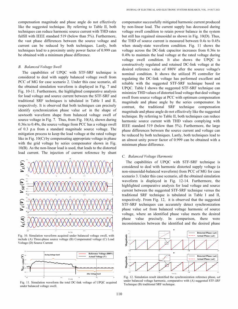
Fig. 8. Simulation waveform acquired under balanced voltage sag, with include (A) Three-phase source voltage (B) Compensated voltage (C) Load Voltage (D) Load Current (E) Compensated current (F) Source Current
JOURNAL OF ELECTRICAL AND ELECTRONIC SYSTEMS RESEARCH, VOL. 19 OCT 2021
110
compensation magnitude and phase angle do not effectively like the suggested technique. By referring to Table II, both techniques can reduce harmonic source current with THD rates fulfill with IEEE standard 519 (below than 5%). Furthermore, the vast phase differences between the source voltage and current can be reduced by both techniques. Lastly, both techniques lead to a proximity unity power factor of 0.999 can be obtained with a minimum phase difference.
B. Balanced Voltage Swell The capabilities of UPQC with STF-SRF technique is
considered to deal with supply balanced voltage swell from PCC of MG for case scenario 2. Under this case scenario, all the obtained simulation waveform is displayed in Fig. 7 and Fig. 10-11. Furthermore, the highlighted comparative analysis for load voltage and source current between the STF-SRF and traditional SRF techniques is tabulated in Table I and II, respectively. It is observed that both techniques can precisely identify synchronization phase value 𝜔𝜔𝜔𝜔 in the shape of sawtooth waveform shape from balanced voltage swell of source voltage in Fig. 7. Thus, from Fig. 10(A), shown during 0.36s to 0.49s, the source voltage from PCC has a voltage swell of 0.3 p.u from a standard magnitude source voltage. The mitigation process to keep the load voltage at the rated voltage like in Fig. 10(C) by compensating appropriate voltage in phase with the grid voltage by series compensator shown in Fig. 10(B). As the non-linear load is used, that leads to the distorted load current. The injection of current reference by shunt
compensator successfully mitigated harmonic current produced by non-linear load. The current supply has decreased during voltage swell condition to retain power balance in the system but still has regained sinusoidal as shown in Fig. 10(D). Thus, the THD of source current is measured between 0.4s to 0.45s when steady-state waveform condition. Fig. 11 shows the voltage across the DC-link capacitor increases from 0.36s to 0.49s to maintain the load voltage at the rated voltage during voltage swell condition. It also shows the UPQC is constructively regulated and retained DC-link voltage at the desired reference value of 880V after the source voltage's nominal condition. It shows the utilized PI controller for regulating the DC-link voltage has performed excellent and reliable with the suggested STF-SRF technique based on UPQC. Table I shows the suggested STF-SRF technique can minimize THD values of distorted load voltage that deal voltage swell from source voltage at PCC with optimum compensation magnitude and phase angle by the series compensator. In contrast, the traditional SRF technique compensation magnitude and phase angle do not effectively like the suggested technique. By referring to Table II, both techniques can reduce harmonic source current with THD values complying with IEEE standard 519 (below than 5%). Furthermore, the large phase differences between the source current and voltage can be reduced by both techniques. Lastly, both techniques lead to an almost unity power factor of 0.999 can be obtained with a minimum phase difference.
C. Balanced Voltage Harmonic The capabilities of UPQC with STF-SRF technique is
considered to deal with harmonic distorted supply voltage (a non-sinusoidal-balanced waveform) from PCC of MG for case scenario 3. Under this case scenario, all the obtained simulation waveform is displayed in Fig. 12-14. Furthermore, the highlighted comparative analysis for load voltage and source current between the suggested STF-SRF technique versus the traditional SRF technique is tabulated in Table I and II, respectively. From Fig. 12, it is observed that the suggested STF-SRF techniques can accurately detect synchronization phase value 𝜔𝜔𝜔𝜔 from balanced voltage harmonic of source voltage, where an identified phase value meets the desired phase value precisely. In comparison, there were inconsistencies between the identified and the desired phase
Fig. 10. Simulation waveform acquired under balanced voltage swell, with include (A) Three-phase source voltage (B) Compensated voltage (C) Load Voltage (D) Source Current
Fig. 12. Simulation result identified the synchronization reference phase, 𝜔𝜔𝜔𝜔 under balanced voltage harmonic, comparative with (A) suggested STF-SRF Technique (B) traditional SRF technique.
Mag
nitu
deM
agni
tude
Detected Phase Actual Phase
Detected Phase Actual Phase
Fig. 11. Simulation waveform the total DC-link voltage of UPQC acquired under balanced voltage swell.
Reference Voltage (880V)Actual Voltage (V)
During Voltage Swell
After Voltage Swell
Mansor et al.: Mitigation of Power Quality Issues using UPQC with STF-SRF Technique Under Adverse Voltage Source Condition
111
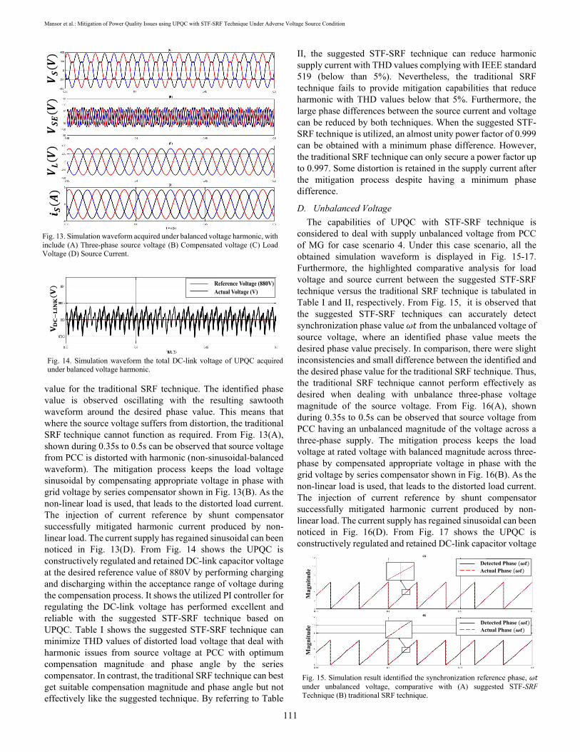
value for the traditional SRF technique. The identified phase value is observed oscillating with the resulting sawtooth waveform around the desired phase value. This means that where the source voltage suffers from distortion, the traditional SRF technique cannot function as required. From Fig. 13(A), shown during 0.35s to 0.5s can be observed that source voltage from PCC is distorted with harmonic (non-sinusoidal-balanced waveform). The mitigation process keeps the load voltage sinusoidal by compensating appropriate voltage in phase with grid voltage by series compensator shown in Fig. 13(B). As the non-linear load is used, that leads to the distorted load current. The injection of current reference by shunt compensator successfully mitigated harmonic current produced by non-linear load. The current supply has regained sinusoidal can been noticed in Fig. 13(D). From Fig. 14 shows the UPQC is constructively regulated and retained DC-link capacitor voltage at the desired reference value of 880V by performing charging and discharging within the acceptance range of voltage during the compensation process. It shows the utilized PI controller for regulating the DC-link voltage has performed excellent and reliable with the suggested STF-SRF technique based on UPQC. Table I shows the suggested STF-SRF technique can minimize THD values of distorted load voltage that deal with harmonic issues from source voltage at PCC with optimum compensation magnitude and phase angle by the series compensator. In contrast, the traditional SRF technique can best get suitable compensation magnitude and phase angle but not effectively like the suggested technique. By referring to Table
II, the suggested STF-SRF technique can reduce harmonic supply current with THD values complying with IEEE standard 519 (below than 5%). Nevertheless, the traditional SRF technique fails to provide mitigation capabilities that reduce harmonic with THD values below that 5%. Furthermore, the large phase differences between the source current and voltage can be reduced by both techniques. When the suggested STF-SRF technique is utilized, an almost unity power factor of 0.999 can be obtained with a minimum phase difference. However, the traditional SRF technique can only secure a power factor up to 0.997. Some distortion is retained in the supply current after the mitigation process despite having a minimum phase difference.
D. Unbalanced Voltage The capabilities of UPQC with STF-SRF technique is
considered to deal with supply unbalanced voltage from PCC of MG for case scenario 4. Under this case scenario, all the obtained simulation waveform is displayed in Fig. 15-17. Furthermore, the highlighted comparative analysis for load voltage and source current between the suggested STF-SRF technique versus the traditional SRF technique is tabulated in Table I and II, respectively. From Fig. 15, it is observed that the suggested STF-SRF techniques can accurately detect synchronization phase value 𝜔𝜔𝜔𝜔 from the unbalanced voltage of source voltage, where an identified phase value meets the desired phase value precisely. In comparison, there were slight inconsistencies and small difference between the identified and the desired phase value for the traditional SRF technique. Thus, the traditional SRF technique cannot perform effectively as desired when dealing with unbalance three-phase voltage magnitude of the source voltage. From Fig. 16(A), shown during 0.35s to 0.5s can be observed that source voltage from PCC having an unbalanced magnitude of the voltage across a three-phase supply. The mitigation process keeps the load voltage at rated voltage with balanced magnitude across three-phase by compensated appropriate voltage in phase with the grid voltage by series compensator shown in Fig. 16(B). As the non-linear load is used, that leads to the distorted load current. The injection of current reference by shunt compensator successfully mitigated harmonic current produced by non-linear load. The current supply has regained sinusoidal can been noticed in Fig. 16(D). From Fig. 17 shows the UPQC is constructively regulated and retained DC-link capacitor voltage
Fig. 13. Simulation waveform acquired under balanced voltage harmonic, with include (A) Three-phase source voltage (B) Compensated voltage (C) Load Voltage (D) Source Current.
Fig. 14. Simulation waveform the total DC-link voltage of UPQC acquired under balanced voltage harmonic.
Reference Voltage (880V)Actual Voltage (V)
Fig. 15. Simulation result identified the synchronization reference phase, 𝜔𝜔𝜔𝜔 under unbalanced voltage, comparative with (A) suggested STF-SRF Technique (B) traditional SRF technique.
Mag
nitu
deM
agni
tude
Detected Phase Actual Phase
Detected Phase Actual Phase

JOURNAL OF ELECTRICAL AND ELECTRONIC SYSTEMS RESEARCH, VOL. 19 OCT 2021
112
at the desired reference value of 880V by performing charging and discharging within the acceptance range of voltage during the compensation process. It shows the utilized PI controller for regulating the DC-link voltage has performed excellent and reliable with the suggested STF-SRF technique based on UPQC. Table I shows the suggested STF-SRF technique can minimize THD values of distorted load voltage that deal unbalanced magnitude issues across three-phase from source voltage at PCC with optimum compensation magnitude and phase angle by the series compensator. However, the traditional SRF technique compensation magnitude and phase angle do not effectively like the suggested technique. By referring to Table II, the suggested STF-SRF technique can reduce harmonic supply current with THD values complying with IEEE standard 519 (below than 5%). However, the traditional SRF technique fails to provide mitigation capabilities that reduce harmonic with THD values below that 5%. Furthermore, the large phase differences between the source current and voltage can be reduced by both techniques. When the suggested STF-SRF technique is utilized, an almost unity power factor of 0.999 can be obtained with a minimum phase difference. However, the traditional SRF technique can only secure a power factor up to 0.998 because some distortion retained in the supply current after the mitigation process despite having a minimum phase difference.
E. Non-sinusoidal-Unbalanced Voltage The capabilities of UPQC with STF-SRF technique is
considered to deal with supply non-sinusoidal (harmonic distorted) and unbalanced magnitude voltage across three-phase from PCC of MG for case scenario 5. Under this case scenario, all the obtained simulation waveform is displayed in Fig. 18-20. Furthermore, the highlighted of comparative analysis for load voltage and source current between suggested STF-SRF technique versus traditional SRF technique is tabulated in Table I and II, respectively. From Fig. 18 observed that the suggested STF-SRF techniques could accurately detect synchronization phase value 𝜔𝜔𝜔𝜔 from non-sinusoidal-unbalanced voltage of source voltage. An identified phase value meets the desired phase value precisely. In comparison, there were slight inconsistencies between the identified and the desired phase value for the traditional SRF technique. Thus, the traditional SRF technique cannot perform effectively when dealing with unbalance three-phase voltage magnitude and harmonic distorted of source voltage. From Fig. 19(A), shown during 0.35s to 0.5s can be observed that source voltage from PCC having an unbalanced magnitude of the voltage across three-phase supply with distorted harmonic. The mitigation process to keep the load voltage at rated voltage with balanced magnitude across three-phase by compensated appropriate voltage in phase with the grid voltage by series compensator shown in Fig. 19(B). As the non-linear load is used, that leads to the distorted load current. The injection of current reference by shunt compensator successfully mitigated harmonic current produced by non-linear load. The source current has regained sinusoidal can been noticed in Fig. 19(D). Furthermore, from Fig. 20 shows the UPQC is constructively regulated and retained DC-link capacitor voltage at the desired reference value of 880V by performing charging and discharging within the acceptance range of voltage during the compensation process. It is showing the utilize PI controller for regulating the DC-link voltage have performed excellent and reliable with suggested STF-SRF technique based on UPQC. Table I shows the suggested STF-SRF technique can minimize THD values of distorted load voltage that deal unbalanced magnitude issues across three-phase with distorted harmonic from supply voltage at PCC with optimum compensation magnitude and phase angle by the series compensator. However, the traditional SRF technique compensation magnitude and phase angle do not effectively like suggested technique. By referring to Table II, the suggested STF-SRF technique can reduce harmonic supply
Fig. 16. Simulation waveform acquired under Unbalanced Voltage, with include (A) Three-phase source voltage (B) Compensated voltage (C) Load Voltage (D) Source Current.
Fig. 17. Simulation waveform the total DC-link voltage of UPQC acquired under unbalanced voltage.
Reference Voltage (880V)Actual Voltage (V)
Fig. 18. Simulation result identified the synchronization reference phase, 𝜔𝜔𝜔𝜔 under non-sinusoidal-unbalanced voltage, comparative with (A) suggested STF-SRF Technique (B) traditional SRF technique.
Mag
nitu
deM
agni
tude
Detected Phase Actual Phase
Detected Phase Actual Phase

Mansor et al.: Mitigation of Power Quality Issues using UPQC with STF-SRF Technique Under Adverse Voltage Source Condition
113
current with THD values complying with IEEE standard 519 (below than 5%). However, the traditional SRF technique fails to provide mitigation capabilities that reduce harmonic with THD values below that 5%. Furthermore, the large phase differences that emerged between the source current and voltage can reduce by both techniques. When the suggested STF-SRF technique is utilized, almost unity power factor of 0.999 can be obtained with a minimum phase difference. However, the traditional SRF technique can only secure a power factor up to 0.998 because some distortion retained in the
supply current after the mitigation process despite having a minimum phase difference. Generally based on case scenario 1 to 5, all the result shows the suggested STF-SRF technique design method based on UPQC and working performance can be accepted especially during dealing with unbalance and distorted source voltage condition. Based on Table I and II, the suggested technique is revealed the ideal sinusoidal load voltage has been regained with low THD values below than 0.29% with appropriate compensation magnitude. Other than that, by complying the IEEE standard 519, the most distorted source current has been recovered with low THD values between 1.99% to 3.15% with minimizing the phase differences to achieving 0.999 of power factor which is closed to unity. In addition, all DC-link capacitor voltages have been controlled as required, meaning the UPQC can properly mitigate power quality issues in the
operating power system.
TABLE I COMPARATIVE LOAD VOLTAGE ANALYSIS OF THE SUGGESTED UPQC USING STF-SRF TECHNIQUE AND TRADITIONAL SRF TECHNIQUE:
Analysis Parameter
Balance Voltage Sag Balance Voltage Swell Balance Voltage Harmonic
Unbalance Voltage Non-sinusoidal-Unbalanced Voltage
Phase a
Phase b
Phase c
Phase a
Phase b
Phase c
Phase a
Phase b
Phase c
Phase a
Phase b
Phase c
Phase a
Phase b
Phase c
Before Connecting UPQC THD value (%) 17.65 19.36 19.28 16.84 17.63 17.03 22.62 24.11 24.22 12.14 13.54 13.33 24.63 26.31 25.74
Phase Angle (°) 0 -120 120 0 -120 120 0 -120 120 0 -120 120 0 -120 120
After Connecting UPQC with the suggested STF-SRF technique THD value (%) 0.25 0.25 0.25 0.25 0.25 0.25 0.28 0.28 0.28 0.29 0.29 0.29 0.29 0.29 0.29
Phase Angle (°) 0 -120 120 0 -120 120 0 -120 120 0 -120 120 0 -120 120
Compensation Magnitude (%)
100 99.64 99.814 100 100.3 100.4 100 100.1 99.78 100 99.89 99.81 100.1 99.78 99.64
After Connecting UPQC with the traditional SRF technique THD value (%) 0.72 1.86 1.98 0.61 1.54 2.00 0.31 0.31 0.32 0.65 1.03 1.11 0.93 2.33 2.51
Phase Angle (°) 0 -120.2 119.9 0 -120.2 199.9 0 -120.2 199.9 0 -120.2 199.9 0 -120.2 199.9
Compensation Magnitude (%)
100 99.2 99.43 100 100.6 100.4 99.97 99.48 100.2 99.94 99.68 100.4 99.70 99.48 100.5
Fig. 19. Simulation waveform acquired under non-sinusoidal-unbalanced voltage, with include (A) Three-phase source voltage (B) Compensated voltage (C) Load Voltage (D) Source Current.
Fig. 20. Simulation waveform the total DC-link voltage of UPQC acquired under non-sinusoidal-unbalanced voltage.
Reference Voltage (880V)Actual Voltage (V)

JOURNAL OF ELECTRICAL AND ELECTRONIC SYSTEMS RESEARCH, VOL. 19 OCT 2021
114
TABLE II COMPARATIVE SOURCE CURRENT ANALYSIS OF THE SUGGESTED UPQC USING STF-SRF TECHNIQUE AND TRADITIONAL SRF TECHNIQUE:
Analysis Parameter
Balance Voltage Sag Balance Voltage Swell Balance Voltage Harmonic
Unbalance Voltage Non-sinusoidal-Unbalanced Voltage
Phase a
Phase b
Phase c
Phase a
Phase b
Phase c
Phase a
Phase b
Phase c
Phase a
Phase b
Phase c
Phase a
Phase b
Phase c
Before Connecting UPQC THD value (%) 48.49 46.57 49.43 48.49 46.57 49.43 53.28 52.92 53.28 48.49 46.57 49.43 59.49 57.57 59.43
Phase Difference (°) 10.6 9.1 9.8 10.6 9.1 9.8 12.5 11.3 9.2 11.6 9.4 10.3 10.2 9.8 9.3.7
Power Factor 0.913 0.860 0.920 0.913 0.860 0.920 0.808 0.812 0.905 0.903 0.810 0.910 0.906 0.850 0.926 After Connecting UPQC with the suggested STF-SRF technique
THD value (%) 1.99 2.13 2.76 1.98 2.59 2.88 2.09 2.67 3.15 2.79 2.86 3.01 2.81 2.69 2.99
Phase Difference (°) 0.3 0.2 0.4 0.2 0.2 0.5 0.4 0.3 0.5 0.2 0.3 0.3 0.2 0.4 0.3
Power Factor 0.999 0.999 0.999 0.999 0.999 0.999 0.999 0.999 0.999 0.999 0.999 0.999 0.999 0.999 0.999 After Connecting UPQC with the traditional SRF technique
THD value (%) 2.89 2.80 3.00 2.66 2.50 2.81 4.12 5.75 6.14 5.09 5.11 5.69 5.87 5.91 6.04
Phase Difference (°) 0.5 0.3 0.6 0.4 0.4 0.7 0.5 0.4 0.7 0.3 0.5 0.4 0.5 0.6 0.4
Power Factor 0.999 0.999 0.999 0.999 0.999 0.999 0.997 0.997 0.996 0.998 0.996 0.997 0.997 0.996 0.995
IV. CONCLUSION The use of the STF-SRF technique-based on UPQC improves
standard UPQC in dealing with adverse source voltage conditions. Besides that, this technique is applied effectively in the UPQC controller scheme. The modified SRF technique integrated with STF-UVG as phase synchronization which can lead to UPQC controller generated reference current and voltage in phase with the operating power system. Furthermore, the UPQC with STF-SRF technique is formed without relying on the complexity of PLL components. The compensation of current and voltage is performed successfully following the adverse source voltage condition and consideration of non-linear load. This is to ensure the system stability and obtains almost unity power factor. It is verified that the harmonics are minimized in source current by following the IEEE-519 standard. On top of that, the ideal sinusoidal load voltage has been regained with low THD values with appropriate compensation magnitude. Therefore, the suggested STF-SRF technique based on the UPQC system can enhance the overall performance and more reliable to mitigate power quality issues by considering dealing with adverse source voltage conditions in the power grid system.
ACKNOWLEDGMENT This research was supported by the Long-Term Research
Grant (LRGS), Ministry of Education Malaysia for the program titled "Decarbonisation of Grid with an Optimal Controller and Energy Management for Energy Storage System in Microgrid Applications" with project code 600-IRMI/LRGS 5/3 (001/2019). The authors would also like to acknowledge The Institute of Research Management & Innovation (IRMI), Universiti Teknologi MARA (UiTM), Shah Alam, Selangor, Malaysia for the facilities provided to support on this research.
REFERENCES [1] E. Planas, A. Gil-De-Muro, J. Andreu, I. Kortabarria, and I. Martínez
De Alegría, "General aspects, hierarchical controls and droop methods in microgrids: A review," Renew. Sustain. Energy Rev., vol. 17, pp. 147–159, 2013.
[2] Y. Parag and M. Ainspan, "Sustainable microgrids: Economic, environmental and social costs and benefits of microgrid deployment," Energy Sustain. Dev., vol. 52, pp. 72–81, 2019.
[3] M. F. Zia, E. Elbouchikhi, and M. Benbouzid, "Microgrids energy management systems: A critical review on methods, solutions, and prospects," Appl. Energy, vol. 222, no. April, pp. 1033–1055, 2018.
[4] P. K. Ray, S. R. Mohanty, N. Kishor, and J. P. S. Catalao, "Optimal feature and decision tree-based classification of power quality disturbances in distributed generation systems," IEEE Trans. Sustain. Energy, vol. 5, no. 1, pp. 200–208, 2014.
[5] S. K. Khadem, M. Basu, and M. F. Conlon, "A comparative analysis of placement and control of UPQC in DG integrated grid connected network," Sustain. Energy, Grids Networks, vol. 6, no. xxxx, pp. 46–57, 2016.
[6] E. Hossain, M. R. Tur, S. Padmanaban, S. Ay, and I. Khan, "Analysis and Mitigation of Power Quality Issues in Distributed Generation Systems Using Custom Power Devices," IEEE Access, vol. 6, no. c, pp. 16816–16833, 2018.
[7] M. Yavari, S. H. Edjtahed, and S. A. Taher, "A non-linear controller design for UPQC in distribution systems," Alexandria Eng. J., vol. 57, no. 4, pp. 3387–3404, 2018.
[8] H. Fujita and H. Akagi, "The unified power quality conditioner: The integration of series- and shunt-active filters," IEEE Trans. Power Electron., vol. 13, no. 2, pp. 315–322, 1998.
[9] M. A. Mansor, M. M. Othman, I. Musirin, and S. Z. M. Noor, "Dynamic voltage restorer (DVR) in a complex voltage disturbance compensation," Int. J. Power Electron. Drive Syst., vol. 10, no. 4, pp. 2222–2230, 2019.
[10] S. A. Taher, H. T. Fard, and E. B. Kashani, "New switching approach for DVR using one cycle control method," Ain Shams Eng. J., vol. 9, no. 4, pp. 2227–2254, 2018.
[11] Y. Hoon, M. A. M. Radzi, M. K. Hassan, and N. F. Mailah, "Control algorithms of shunt active power filter for harmonics mitigation: A review," Energies, vol. 10, no. 12, 2017.
[12] W. U. Tareen and S. Mekhilef, "Transformer-less 3P3W SAPF (three-phase three-wire shunt active power filter) with line-interactive UPS (uninterruptible power supply) and battery energy storage stage," Energy, vol. 109, pp. 525–536, 2016.
[13] S. B. Karanki, N. Geddada, M. K. Mishra, and B. K. Kumar, "A modified three-phase four-wire UPQC topology with reduced DC-
Mansor et al.: Mitigation of Power Quality Issues using UPQC with STF-SRF Technique Under Adverse Voltage Source Condition
115
link voltage rating," IEEE Trans. Ind. Electron., vol. 60, no. 9, pp. 3555–3566, 2013.
[14] S. Golestan, J. M. Guerrero, and J. C. Vasquez, "Three-Phase PLLs: A Review of Recent Advances," IEEE Trans. Power Electron., vol. 32, no. 3, pp. 1897–1907, 2017.
[15] S. Devassy and B. Singh, "Design and Performance Analysis of Three-Phase Solar PV Integrated UPQC," IEEE Trans. Ind. Appl., vol. 54, no. 1, pp. 73–81, 2018.
[16] M. Kesler and E. Ozdemir, "Synchronous-reference-frame-based control method for UPQC under unbalanced and distorted load conditions," IEEE Trans. Ind. Electron., vol. 58, no. 9, pp. 3967–3975, 2011.
[17] S. Devassy and B. Singh, "Modified pq-Theory-Based Control of Solar-PV-Integrated UPQC-S," IEEE Trans. Ind. Appl., vol. 53, no. 5, pp. 5031–5040, 2017.
[18] V. G. Kinhal, P. Agarwal, and H. O. Gupta, "Performance investigation of neural-network-based unified power-quality conditioner," IEEE Trans. Power Deliv., vol. 26, no. 1, pp. 431–437, 2011.
[19] K. Hasan, M. M. Othman, N. F. A. Rahman, M. A. Hannan, and I. Musirin, "Significant implication of unified power quality conditioner in power quality problems mitigation," Int. J. Power Electron. Drive Syst., vol. 10, no. 4, p. 2231, 2019.
[20] A. Teke, L. Saribulut, and M. Tumay, "A novel reference signal generation method for power-quality improvement of unified power-quality conditioner," IEEE Trans. Power Deliv., vol. 26, no. 4, pp. 2205–2214, 2011.
[21] R. Kumar Patjoshi, R. Panigrahi, and V. Ratnam Kolluru, "Variable non-linear gain fuzzy with improved synchronous reference frame control strategy for performance enhancement of unified power quality conditioner," Ain Shams Eng. J., no. xxxx, 2020.
[22] A. Jeraldine Viji and T. Aruldoss Albert Victoire, "Enhanced PLL based SRF control method for UPQC with fault protection under unbalanced load conditions," Int. J. Electr. Power Energy Syst., vol. 58, pp. 319–328, 2014.
[23] J. Yu, Y. Xu, Y. Li, and Q. Liu, "An Inductive Hybrid UPQC for Power Quality Management in Premium-Power-Supply-Required Applications," IEEE Access, vol. 8, pp. 113342–113354, 2020.
Muhammad Alif Mansor obtained a Diploma in Electrical Engineering (Power) in 2015 and a Bachelor of Electrical Engineering (Hons) in 2018 from Universiti Teknologi MARA (UiTM), Malaysia. He is currently working toward the M.Sc. degree in Electrical Engineering with the Faculty of Electrical Engineering, UiTM,
Malaysia on the research project of "Classification and Mitigation of Complex Power Quality Problems in Energy Storage System (ESS)". He has been working in Power and Energy with Artificial Intelligence Research laboratory (PEAiRL) group, UiTM, since February 2019. His research interests include power electronics, power quality, renewable energy, and energy storage.
Muhammad Murtadha Othman received his B.Eng. (Hons) from Staffordshire University, England in 1998; M.Sc from Universiti Putra Malaysia in 2000 and PhD from Universiti Kebangsaan Malaysia in 2006. He is currently working as a Director for the UiTM-Solar Energy Research (U-SER) Centre under the project
of 50MW LSSPV at Gambang, Pahang. He is also an Associate Professor at the Faculty of Electrical Engineering (FEE),
Universiti Teknologi MARA (UiTM), Malaysia. He served as the Head of Department of the Centre for Electrical Power Engineering Studies (CEPES) from February 2009 to December 2010. From 2012 until present he served two times as the Deputy Director for the collaborative research project under the auspices of Ministry of Energy, Green Technology and Water (KeTTHA), Malaysia, and also the Public Works Department (JKR), Malaysia. He also served as the Deputy Director for service commercialization on energy efficiency technology under the collaboration with Centre of Excellence for Engineering and Technology JKR (CREaTE), Malaysia. He was previously appointed as the Chairman for the Energy Efficiency Committee in FEE, UiTM and also the committee member in the Master of Electrical Power Engineering Programme, Faculty of Engineering, Universiti Putra Malaysia (UPM). He has served as the panel assessor for research grant proposals at the Ministry of Higher Education (MOHE), Malaysia and Latvian Science Council, Europe. His area of research interests are artificial intelligence, energy efficiency, transfer capability assessment, integrated resource planning, demand side management, hybrid renewable energy, power system stability, reliability studies in a deregulated power system, power quality and active power filters
Ismail Musirin obtained Bachelor of Electrical Engineering (Hons) in 1990 from Universiti Teknologi Malaysia, MSc Pulsed Power Technology in 1992 from University of Strathclyde, United Kingdom and PhD in Electrical Engineering from Universiti Teknologi MARA (UiTM), Malaysia in 2005. He
started his higher education at Universiti Teknologi Malaysia (UTM) and gained Diploma in Electrical Power Engineering in 1987. He has been the Head of Programme for Diploma of Electrical Engineering, UiTM for 3 years (2004-2007), Head of Department Electrical Power Engineering for year (2007), Deputy Dean Research and Industrial Networking for 2 years (2008-2010) and Director for Community of Research UiTM for 4 years (2014-2017). He is currently a Professor of Power System at the Faculty of Electrical Engineering. He has authored and co-authored 2 books, over 300 papers in international journal and indexed conferences. He is also an international journal reviewer for IEEE Transactions, Elsevier Science, WSEAS, John Wiley, IET and some other publishers. His research interest includes artificial intelligence, optimization techniques, power system analysis, renewable energy, distributed generation and power system stability. He is a senior member of International Association of Computer Science and Information Technology (IACSIT), member of Artificial Immune System Society (ARTIST) and member of International Association of Engineers (IAENG).

JOURNAL OF ELECTRICAL AND ELECTRONIC SYSTEMS RESEARCH, VOL. 19 OCT 2021
116
Siti Zaliha Binti Mohammad Noor obtained Bachelor of Electrical Engineering (Hons) in 2005, MSc Power Electronics in 2008 and PhD in Electrical Engineering in 2018 from Universiti Teknologi MARA (UiTM), Malaysia. She is currently a Senior Lecturer at the Faculty of Electrical Engineering, UiTM.
She has authored and co-authored over 35 technical papers in indexed international journal and conferences. Her research interests are renewable energy, power electronics, modeling and simulation, signal processing and embedded controller applications. She is a Certified Energy Manager, Certified Professional in Measurement and Verification CPMV), and Qualified Person (QP) SEDA Malaysia Grid-Connected Solar Photovoltaic Systems Design. She is also attached to industry collaborations as the Subject Matter Expert (SME) for the Photovoltaic (PV) system and energy audit. She also received a gold award on the e-ConDev2018 for Course Renewable Energy -Friends of The World as an educator and developer of the course. Currently, more than 500 students joined the course worldwide.