Mitigation of Power Quality Issues using PV- UPQC and MTG ...
9
Mitigation of Power Quality Issues using PV- UPQC and MTG - UPQC in a Distribution system A. Radhika 1 , A. Shunmugalatha 2 , N. Karuppiah 3 , M. Devaki 4 1 Assistant Professor, Department of EEE, Velammal College of Engineering and Technology, Madurai, Tamilnadu, India [email protected] 2 Professor and Head, Department of EEE, Velammal College of Engineering and Technology, Madurai, Tamilnadu, India 3 Associate Professor, Department of EEE, Vardhaman College of Engineering, Shamshabad, Hyderabad, Telangana, India [email protected] 4 Assistant Professor, Department of EEE, Velammal College of Engineering and Technology, Madurai, Tamilnadu, India Abstract: Maintaining power quality at the distribution end is a serious concern that the power system faces today. The usage of power conditioning devices like UPQC mitigates the power quality problems to certain extent. Nowadays the distributed generation sources like photo voltaic cells and micro turbine generation are integrated in the existing distribution system to improve power quality and reliability. This paper proposes the installation of Photo Voltaic cell - Unified Power Quality Conditioner and Micro Turbine Generator - Unified Power Quality Conditioner in a distribution system to solve the power quality problems. Also this paper compares the effective usage of PV- UPQC and MTG – UPQC in the distribution system to mitigate the power quality issues. Due to the installation of PV-UPQC or MTG-UPQC the total harmonic distortion in the source current is reduced and the problem of voltage sag is avoided. MTG-UPQC installed in the distribution system performs better in the mitigation of power quality issues than PV-UPQC. The results are validated using MATLAB/Simulink. Keywords: Microturbine Generation (MTG), Photo Voltaic (PV), Voltage Sag, Total Harmonic Distortion (THD) 1. INTRODUCTION Normally, in three phase power systems, all the three phase voltages are displaced by 120 o each resulting in sinusoidal and equal magnitude voltages in each phase. But at the point of utilization, these voltages become unbalanced and suffer from various power quality problems such as fundamental frequency deviation, fundamental phase angle deviation and unequal levels of harmonic distortion between the phases. This is due to the nature of unpredictable loads and deployment of Adjustable Speed Drives (ASD) at customer premises as Energy saving measure [1,2]. Now-a-days due to the usage of inverters in residential households the problem of power quality at the customer end is alarming. In many applications, at the customer end, power electronic converters serves as the interface for many electronic loads. Most of these power electronic converters consist of a diode rectifier, a dc link capacitor and a PWM inverter which draws non sinusoidal currents. Hence the problem of harmonic distortion arises [3-5]. In the proposed paper the need to balance the voltage at the customer premises is discussed. The voltage balance problem becomes difficult due to the large usage of single phase non linear switch mode power supply based loads such as computers. Moreover the increase of lighting loads in a particular phase also imposes serious voltage unbalance problems [6]. Many measures are being taken to correct the voltage unbalance in the distribution system and are discussed in literature. The addition of passive filters reduces the voltage unbalance by adding reactive elements parallel to the load. Also the introduction of thyristor controlled shunt compensators in the distribution system reduces the voltage unbalance. But the disadvantage of this system is the introduction of harmonics due to the power electronic components [7]. The installation of custom power devices is a solution for Voltage Unbalance problem. UPQC is used in this paper to mitigate the voltage sag and swell. It consists of both series and shunt converter and by controlling the magnitude of series injected voltage and phase angle, voltage profile is improved in the distribution system [8]. The integration of distributed generation in the distribution system is increasing day by day. The distributed generation includes the penetration of photo voltaic cells, Micro turbine generation, wind, fuel cell and other sources. The penetration of these sources in the distribution network reduces pollution, increases reliability, effective load management and reduces losses [9]. In recent times the installation of single phase grid connected roof top photo voltaic cells in residential homes
Transcript of Mitigation of Power Quality Issues using PV- UPQC and MTG ...

Mitigation of Power Quality Issues using PV- UPQC and MTG - UPQC in
a Distribution system
A. Radhika1, A. Shunmugalatha2, N. Karuppiah3, M. Devaki4
1 Assistant Professor, Department of EEE, Velammal College of Engineering and Technology, Madurai, Tamilnadu, India
[email protected] 2Professor and Head, Department of EEE, Velammal College of Engineering and Technology, Madurai, Tamilnadu, India 3Associate Professor, Department of EEE, Vardhaman College of Engineering, Shamshabad, Hyderabad, Telangana, India
4Assistant Professor, Department of EEE, Velammal College of Engineering and Technology, Madurai, Tamilnadu, India
Abstract: Maintaining power quality at the distribution end is a serious concern that the power system faces today. The usage of power conditioning devices like UPQC mitigates the power quality problems to certain extent. Nowadays the distributed generation sources like photo voltaic cells and micro turbine generation are integrated in the existing distribution system to improve power quality and reliability. This paper proposes the installation of Photo Voltaic cell - Unified Power Quality Conditioner and Micro Turbine Generator - Unified Power Quality Conditioner in a distribution system to solve the power quality problems. Also this paper compares the effective usage of PV- UPQC and MTG – UPQC in the distribution system to mitigate the power quality issues. Due to the installation of PV-UPQC or MTG-UPQC the total harmonic distortion in the source current is reduced and the problem of voltage sag is avoided. MTG-UPQC installed in the distribution system performs better in the mitigation of power quality issues than PV-UPQC. The results are validated using MATLAB/Simulink.
Keywords: Microturbine Generation (MTG), Photo Voltaic (PV), Voltage Sag, Total Harmonic Distortion (THD)
1. INTRODUCTION
Normally, in three phase power systems, all the three phase voltages are displaced by 120o each resulting in sinusoidal and equal magnitude voltages in each phase. But at the point of utilization, these voltages become unbalanced and suffer from various power quality problems such as fundamental frequency deviation, fundamental phase angle deviation and unequal levels of harmonic distortion between the phases. This is due to the nature of unpredictable loads and deployment of Adjustable Speed Drives (ASD) at customer premises as Energy saving measure [1,2]. Now-a-days due to the usage of inverters in residential households the problem of power quality at the customer end is alarming. In many applications, at the customer end, power electronic converters serves as the interface for many electronic loads. Most of these power electronic converters consist of a diode rectifier, a dc link capacitor and a PWM inverter which draws non sinusoidal currents. Hence the problem of harmonic distortion arises [3-5]. In the proposed paper the need to balance the voltage at the customer premises is discussed. The voltage balance problem becomes difficult due to the large usage of single phase non linear switch mode power supply based loads such as computers. Moreover the increase of lighting loads in a particular phase also imposes serious voltage unbalance problems
[6]. Many measures are being taken to correct the voltage unbalance in the distribution system and are discussed in literature. The addition of passive filters reduces the voltage unbalance by adding reactive elements parallel to the load. Also the introduction of thyristor controlled shunt compensators in the distribution system reduces the voltage unbalance. But the disadvantage of this system is the introduction of harmonics due to the power electronic components [7].
The installation of custom power devices is a solution for Voltage Unbalance problem. UPQC is used in this paper to mitigate the voltage sag and swell. It consists of both series and shunt converter and by controlling the magnitude of series injected voltage and phase angle, voltage profile is improved in the distribution system [8].
The integration of distributed generation in the distribution system is increasing day by day. The distributed generation includes the penetration of photo voltaic cells, Micro turbine generation, wind, fuel cell and other sources. The penetration of these sources in the distribution network reduces pollution, increases reliability, effective load management and reduces losses [9].
In recent times the installation of single phase grid connected roof top photo voltaic cells in residential homes

imposes serious voltage unbalance problems [10]. The penetration of photo voltaic cell, its rating and its location in the distribution system is unpredictable and so a sensitivity analysis needs to be carried out to study the effect of voltage unbalance. From VU sensitivity analysis it is found that the VU problem is more pronounced at the feeder end [11]. The performance of single and multiple PV arrays connected with UPQC for Voltage Unbalance problem is analyzed [12]. Single phase energy storage systems added to the PV-UPQC distribution system further improves the voltage profile of the system [13].
The MTG system generates power from 25 kW to 500 kW. This type of generation is operated as standalone systems or interconnected with utility applications. The main applications of this type of generation are base load power and peak shaving [14]. The load following performance of MTGs in grid connected and islanded modes are analyzed. The grid tied MTG suffers from voltage instability and synchronization problems. But the performance of MTG for microgrid networks is acceptable [15]. Even in grid tied MTGs the problem of VU is improved using UPQC and by varying the output of MTG. The dynamic behavior of PMSG coupled MTG is analyzed and it is found suitable for micro grid distribution system [16].
The organization of the proposed paper is as follows: Section 1 describes the need for installing power quality devices at the distribution side. Section 2 outlines the role of the proposed system in mitigating power quality issues in the distribution system. Section 3 describes the PV-UPQC compensated distribution system and the role of UPQC and PV in improving the voltage sag and reducing the Total Harmonic Distortion of the source current and voltage. Section 4 discusses about the results obtained through PV-UPQC system. Section 5 details the role of MTG-UPQC in mitigating power quality issues like voltage unbalances and reduction of Total Harmonic Distortion of the source current and voltage. Section 6 discusses about the results obtained through MTG-UPQC system. Section 7 discusses about the results of the proposed system and compares the performance of PV-UPQC and MTG-UPQC systems in mitigating the power quality problems.
1.2. Proposed System
Fig. 1 Block Diagram of the Proposed System
Ps - Power from grid
PL - Power to load
PMTG - Power from micro turbine
PPV - Power from PV Figure 1 shows the block diagram of the proposed system.
UPQC is placed between the Grid and the Load. UPQC along with MTG or PV is inserted into the system during heavy load
conditions. When the non linear loading is high in the proposed
system the source current and the load current suffers from
harmonics and the problem of voltage sag also arises. The
insertion of PV-UPQC or MTG-UPQC in the proposed system
restores the voltage and reduces the Total Harmonic Distortion of source current and load current. The controller compares the
actual voltage with the reference voltage and an error signal is
produced. The series and the shunt converter of UPQC inject
voltage and current in proportional to the error signal to
mitigate the power quality issues.
1.3. PV-UPQC Compensated Distributed System
The block diagram of Distribution system compensated by PV-UPQC is shown in Figure 2. This system has a load connected to the feeder. The feeder is powered by a source. UPQC is placed between source and the load. At the point of common coupling the source voltage Vs would be equal to Thevenin’s voltage Vth and the feeder impedance is assumed to be Thevenin’s impedance. To match the load voltage with the source voltage the series converter of UPQC inserts a voltage so that the load voltage is balanced with respect to source voltage. The shunt converter of UPQC injects a current of proper magnitude to obtain a nearly sinusoidal source current.
Fig. 2 Block Diagram of UPQC compensated
Distribution system
Consider the equivalent circuit of the PV-UPQC
compensated distribution system as shown in Figure 3.
Fig. 3 Equivalent circuit of PV-UPQC compensated
Distribution system

VS - Voltage at power supply
VSR- Series-Active Power Filter for voltage
compensation
VL - Load voltage and
ISh - Shunt-Active Power Filter for current and VSR compensation
In general, the source voltage is expressed as
VS + VSR = VL (1) Balanced sinusoidal load voltage with fixed amplitude V is
obtained from the given expression [16]
VSR = (V − V1P) sin( ωt + θ1P) − VLn − ∑ Vk
∞
k=2
(t) (2)
where
V1P - positive sequence voltage amplitude of
fundamental frequency
Ɵ1P - initial phase of voltage for positive
sequence
VLn - negative sequence component
The load current is given by the expression [16]
IL = I1p cos( ωt + θ1P) sin φ + ILn + ∑ ILk
∞
k=2
(3)
∅1P = φ1P
− θ1P (4)
where
φ1P - initial phase of current for positive sequence
The terminal source current is harmonic free sinusoid and
has the same phase angle as the phase voltage at the load
terminal and is expressed as [16]
IS = IL − Ish (5)
= I1p sin( ωt − θ1p) cos φ1p
(6)
The block diagram of the PV-UPQC system is shown in Figure 4. The PV is connected to the dc link of the UPQC.
The load is fed by PV and utility grid. The nature of load is
non linear and the shunt and series filter provides
compensation for the load. The Simulink diagram of MPPT
controlled PV-UPQC is shown in Figure 5. The simulink
diagram of MPPT controlled PV system is shown in Figure
6.
Fig. 4 Circuit Diagram of PV-UPQC compensated
Distribution system
Fig. 5 SIMULINK diagram of PV-UPQC
compensated Distribution system
The proposed system configuration of UPQC consists of
a 600V, 60 Hz generation system, feeding two transmission
lines through a 3- winding transformer connected in Δ /Δ/Δ,
115/25/25 kV. To verify the working of UPQC for voltage
compensation, both linear and nonlinear loads are connected
at the distribution end. The UPQC is simulated to be in
operation only for the heavy load condition. Thus, UPQC
will be inserted in series with the load to help improving the
supply voltage before it is being fed to the load. The system
parameters of UPQC are given in the Table 1.

Table 1
Parameters of UPQC
Sl. No. Parameters Values
1 Source Voltage 600V
2 No. of bridge arms 3
3 Transition time 0.1 to 0.2 sec
4 Snubber resistance 0.1 mΩ
5 Breaker resistance 0.0001Ω
6 Line frequency 50 Hz
7 Generator Voltage 126 V
Fig. 6 SIMULINK diagram of PV Panel with MPPT
Maximum Power Point Tracking (MPPT) algorithm is
used to improve the performance of the solar panel. This
algorithm tracks the point of maximum power. There are
many types of MPPT algorithm in which Perturb and
Observe type algorithm is implemented in the proposed
system. The implementation of maximum power point
tracking is shown in Figure 7.
Fig. 7 Maximum Power Point Tracking in PV
1.4. Results and Discussion for PV-UPQC
The simulation was done initially without connecting the
PV-UPQC in the three phase grid line. The voltage at the
grid side contains sag, swell and unbalanced current due to
non-linear loads. The voltage sag is created for a period of
500 to 1000 seconds. The grid voltage without PV-UPQC
compensated distribution system is shown in Figure 8.
Figure 9 shows the grid current obtained without PV-
UPQC compensated distribution system for non linear
loads. The THD of grid voltage without PV-UPQC
compensated distribution system is 13.96% as shown in
Figure 10. The THD of source current for non-linear load
without PV-UPQC compensated distribution system is
16.04% as shown in Figure 11.
Fig. 8 Grid voltage obtained without PV-UPQC
Fig. 9 Grid Current obtained without PV-UPQC
Fig. 10 THD of Grid voltage without PV-UPQC
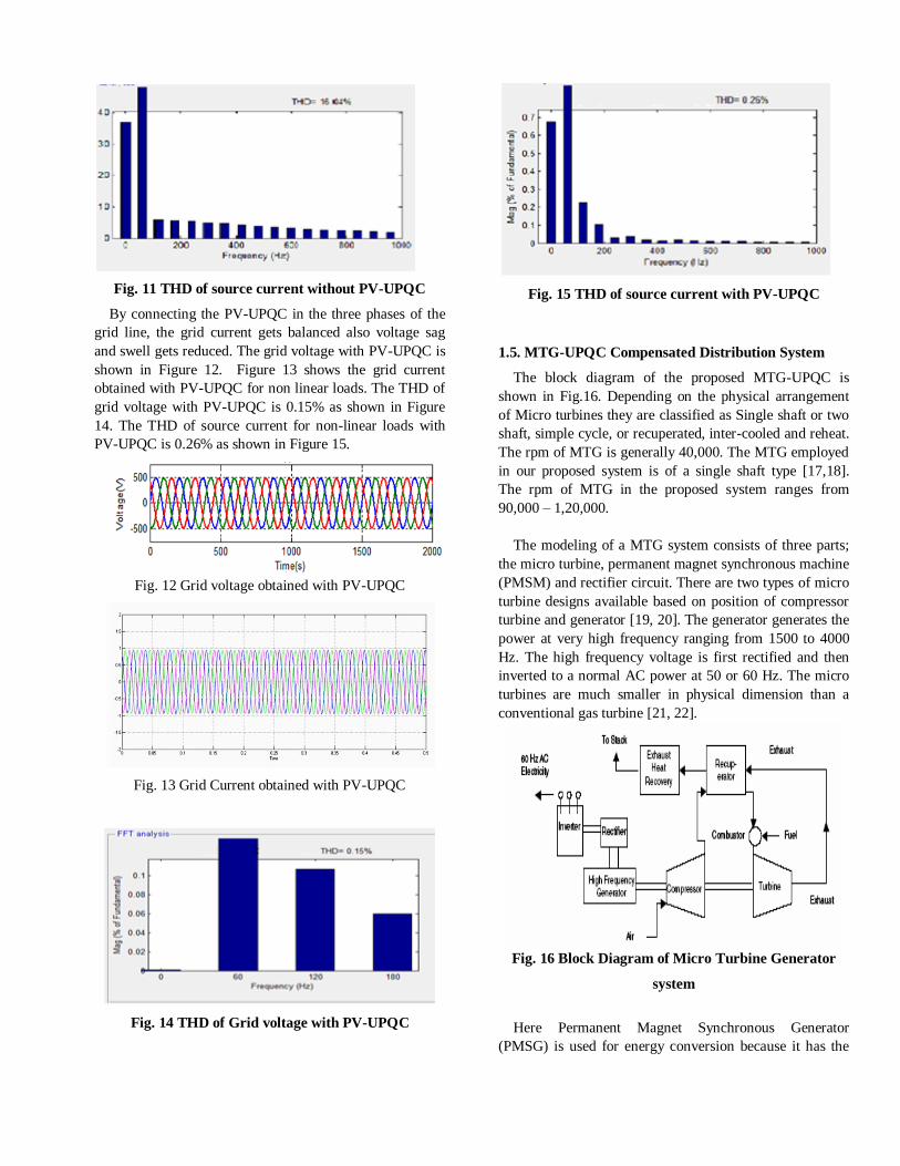
Fig. 11 THD of source current without PV-UPQC
By connecting the PV-UPQC in the three phases of the
grid line, the grid current gets balanced also voltage sag
and swell gets reduced. The grid voltage with PV-UPQC is
shown in Figure 12. Figure 13 shows the grid current
obtained with PV-UPQC for non linear loads. The THD of
grid voltage with PV-UPQC is 0.15% as shown in Figure
14. The THD of source current for non-linear loads with
PV-UPQC is 0.26% as shown in Figure 15.
Fig. 12 Grid voltage obtained with PV-UPQC
Fig. 13 Grid Current obtained with PV-UPQC
Fig. 14 THD of Grid voltage with PV-UPQC
Fig. 15 THD of source current with PV-UPQC
1.5. MTG-UPQC Compensated Distribution System
The block diagram of the proposed MTG-UPQC is
shown in Fig.16. Depending on the physical arrangement
of Micro turbines they are classified as Single shaft or two
shaft, simple cycle, or recuperated, inter-cooled and reheat.
The rpm of MTG is generally 40,000. The MTG employed
in our proposed system is of a single shaft type [17,18].
The rpm of MTG in the proposed system ranges from
90,000 – 1,20,000.
The modeling of a MTG system consists of three parts;
the micro turbine, permanent magnet synchronous machine
(PMSM) and rectifier circuit. There are two types of micro
turbine designs available based on position of compressor
turbine and generator [19, 20]. The generator generates the
power at very high frequency ranging from 1500 to 4000
Hz. The high frequency voltage is first rectified and then
inverted to a normal AC power at 50 or 60 Hz. The micro
turbines are much smaller in physical dimension than a
conventional gas turbine [21, 22].
Fig. 16 Block Diagram of Micro Turbine Generator
system
Here Permanent Magnet Synchronous Generator
(PMSG) is used for energy conversion because it has the

advantage of super high speed operation with small unit
size of the machine which is directly proportional to the
increase in speed [23, 24]. The Simulink diagram of micro
turbine generator system is shown in Figure 17. Figure 18
shows the Simulink diagram of MTG with Permanent
Magnet Synchronous Generator system. Figure 19 shows
the Simulink diagram of MTG-UPQC compensated
distribution system.
Fig. 17 Simulink Diagram of Micro Turbine system
Fig. 18 Simulink Diagram of Micro Turbine Generator system employing Permanent Magnet Synchronous Generator
Fig. 19 Simulink Diagram of MTG-UPQC compensated Distribution system

1.6. Results and Discussion for MTG-UPQC
To demonstrate the effectiveness of the proposed
system, UPQC is simulated using MATLAB/SIMULINK
for the system disturbances. The results are shown for
source voltage and load current. Two conditions are carried
out in this system which is before and after connecting the
MTG-UPQC in the feeder. The simulation was done
initially without connecting the MTG-UPQC in the three
phase grid line. The voltage at the grid side contains sag,
swell and unbalanced current due to non-linear loads. The
grid voltage without MTG-UPQC compensated
distribution system is shown in Figure 20. Figure 21
shows the Load current obtained without MTG-UPQC
compensated distribution system for non linear loads.
Fig. 20 Grid voltage obtained without MTG-UPQC
Fig. 21 Load current obtained without MTG-UPQC
By connecting the MTG-UPQC in the three phases of
the grid line, the grid current gets balanced also voltage sag
and swell gets reduced. The grid voltage with MTG-UPQC
is shown in Figure 22. Figure 23 shows the load current
obtained with MTG-UPQC for non linear loads. The THD
of grid voltage with MTG-UPQC is 0.01% as shown in
Figure 24. The THD of source current for non-linear loads
with MTG-UPQC is 0.03% as shown in Figure 25.
Fig. 22 Grid voltage with MTG-UPQC
Fig. 23 Load current with MTG-UPQC
Fig. 24 THD of Grid voltage with MTG-UPQC

Fig. 25 THD of source current with MTG-UPQC
1.7. Results and Discussion
The performance comparison of the PV-UPQC
compensated and MTG-UPQC compensated distributed
system are shown in Table 2. The percentage THD for grid
voltage and current is calculated with and without
compensation and the results are compared. The
percentage grid voltage THD for the uncompensated
system is 13.96%. For PV-UPQC compensated distribution
system the THD measured is 0.15% and for MTG-UPQC
system it is found to be 0.01%. The percentage source
current THD for the uncompensated system is 16.04%. For
PV-UPQC compensated distribution system the THD
measured is 0.26% and for MTG-UPQC system it is found
to be 0.03%.
Table 2
Performance comparison of PV-UPQC and MTG-
UPQC compensated Distribution System
Percentage
THD
without
PV-
UPQC /
without
MTG-
UPQC
with PV-
UPQC
with MTG-
UPQC
Percentage
Grid
Voltage
THD
13.96 0.15 0.01
Percentage
Source
Current
THD
16.04 0.26 0.03
The results show that MTG-UPQC compensated
distribution system performs better than PV-UPQC
compensated distribution system.
A photovoltaic panel is connected with UPQC in order
to increase the voltage level of the three phase line. P & O
method is proposed to improve the panel efficiency. The
improvement of distorted current is reduced by connecting
UPQC in the feeder. Also, sag, swell and distortion are
also reduced in the distribution side. The PV-UPQC
system provides a significant improvement in the
unbalances and distortions due to linear and non-linear
loads. The THD value gets reduced from 13.96% to 0.15%
after connecting the PV-UPQC. Micro turbine Generator
(MTG) System is also connected with UPQC in order to
increase the voltage level of the three phase line. While
connecting PV to UPQC, the % THD content in the source
voltage and load current after compensation is 0.15% and
0.26%. While connecting Micro turbine to UPQC the %
THD content in the source voltage and load current after
compensation is reduced to 0.01% and 0.03%. Thus, the
efficiency has been improved and % THD content has been
reduced using this MTG-UPQC. The developed MTG-
UPQC provides a significant improvement in the
unbalances and distortions due to linear and non-linear
loads.
The advantage of the proposed PV-UPQC is that it can
be used to compensate for the long voltage interruption and
it is suitable for active power supply. The advantage of the
proposed MTG-UPQC is that in the case of reactive power
compensation there is no need for a real power source at
the DC link. The MTG is useful for this purpose. When the
load is balanced and linear then the real power from the
MTG can be injected into the line as a supplementary
balanced three phase real power. In this way the MTG is
useful.
1.8. Conclusion
The role of custom power device UPQC and the
distributed generation sources such as Photo Voltaic cell
and Micro Turbine Generator in mitigating the power
quality issues like voltage unbalance, reduction of Total
Harmonic Distortion and improvement of voltage sag has
been discussed in this paper. The performance of the two
systems is compared and it is found that MTG-UPQC
system performs better than PV-UPQC system. PV is
useful for real power compensation and MTG is for
reactive power compensation. In future, the performance of
a hybrid distributed generation system along with UPQC
placed in a distribution system and their role in mitigating
power quality issues can be studied.
REFERENCES
[1] Annette von Jouanne, Basudeb Banerjee, “Assessment
of Voltage Unbalance” IEEE Transactions on Power
Delivery, vol. 16, no. 4, pp. 782-790, 2001. [2] Kein Huat Chua, Jianhui Wong, Yun Seng Lim, Phil
Taylor, Ezra Morris, Stella Morris, “Mitigation of Voltage

Unbalance in Low Voltage Distribution Network with
High Level of Photo voltaic system”, Energy Procedia, vol.
12, pp. 495-501, 2011.
[3] Farhad Shahnia, Peter Wolfs, Arindam Ghosh,
“Voltage Unbalance reduction in low voltage feeders by
dynamic switching of residential customers among three phases”, IEEE Power and Energy Society General Meeting
(PES), 21-25 July, 2013, Vancouver, Canada.
[4] Om Prakash Mahela, Abdul Gafoor Shaik, “Power
Quality improvement in distribution network using
DSTATCOM with battery energy storage system”,
International Journal of Electric Power & Energy Systems,
vol. 83, pp. 229-240, 2016.
[5] Shoji Kawasaki, Genki Ogasawara, “Influence analyses
of harmonics on distribution system in consideration of
non linear loads and estimation of harmonic source”,
Journal of International Council on Electrical Engineering,
Taylor & Francis Online, vol. 7, no. 1, pp. 76-82, 2017. [6] Santanu Kumar Dash, Pravat Kumar Ray, “Design and
Modeling of single phase PV-UPQC scheme for power
quality improvement utilizing a novel notch filter based
control algorithm: An Experimental Approach”, Arabian
Journal of Science and Engineering, vol. 43, no. 6, pp.
3083-3102, 2018.
[7] Jingsheng Huang, Meiying Liu, Junjun Zhang, Zhilei
Chen, “Analysis and field test on reactive capability of
photovoltaic power plants based on clusters of inverters”,
Journal of Modern Power Systems and Clean Energy, vol.
5, no. 2, pp. 283-289, 2017. [8] Anup Kumar Panda, Nishant Patnaik, “Combined
operation of a new power angle control unit vector
template based unified power quality conditioner and fuel
stack supply with effective utilization of shunt and series
inverter”, Electric Power Components and Systems, Taylor
& Francis Online, vol. 44, no. 18, pp. 2048-2058, 2016.
[9] K. Kalaipriya, S. Jayachitra, “Power Quality
Improvement using UPQC”, International Journal of
Engineering Research and Applications, vol. 4, no. 5, pp.
1-4, 2014.
[10] F. Shahnia, R. Majumder, A. Ghosh, G. Ledwich, F. Zare, “Sensitivity analysis of voltage imbalance in
distribution networks with rooftop PVs”, IEEE power and
energy society general meeting, 2010.
[11] M. A. Eltawil, Z. Zhao, “Grid-connected photovoltaic
power systems: technical and potential problems – a
review”, Renewable and Sustainable Energy Reviews, vol.
14, no. 1, pp. 112–129, 2010.
[12] Abbas Ketabi, Mohammad Farshadnia, Majid
Malekpour, Rene Feuillet, “A new control strategy for
active power line conditioner (APLC) using adaptive notch
filter”, Elsevier, International Journal of Electrical Power
& Energy Systems, vol. 47, pp. 31-40, 2013. [13] C. M. Cavalcanti, G. M. S. Azevedo, B. A. Amaral, F.
A. S. Neves, “Unified Power Quality Conditioner in a grid
connected photovoltaic system”, Power Quality and
Utilization Journal, vol. 12, no. 2, pp. 59-69, 2006.
[14] Payal Deshpande, Amit Shrivastava, “Comparative
Aspects of single and multiple PV arrays connected with
UPQC”, International Journal of computational
Engineering Research, vol. 4, no. 2, pp. 42-49, 2014.
[15] N. Mallikarjuna, S. Muqthiar Ali, M. Padma Lalitha,
“Improvement of voltage quality of micro turbine generator with matrix converter & venturini techniques",
International Journal of Engineering Research and
Development, vol. 9, no. 8, pp. 41- 49, 2014.
[16] A. Radhika, A. Shunmugalatha, M. Devaki,
“Augmentation of Photovoltaic Power into Grid for Power
Quality Improvement Using Unified Power Quality
Conditioner (UPQC) with P&O Based MPPT”,
International Journal of Advanced Research in Electrical,
Electronics and Instrumentation Engineering, vol. 4, no. 5,
pp. 4358-4366, 2015.
[17] D. N. Gaonkar, Sanjeev Nayak, “Modeling and
Performance Analysis of Micro turbine Based Distributed Generation System - A review”, IEEE Energy Tech, 25-26
May 2011, Cleveland, USA.
[18] A. K. Saha, S. Chowdhury, S. P. Chowdhury, P. A.
Crossley, “Microturbine Based Distributed Generator in
smart grid application" CIRED Seminar on smart grids for
distribution, 23-24, June 2008, Frankfurt, Germany.
[19] Kshitij Tiwari, Tirumalachetty Harinarayanat,
“Increasing the efficiency of Grid Tied Micro wind
Turbines in Low Wind Speed Regimes”, Smart Grid and
Renewable Energy, vol. 5, pp. 249-257, 2014.
[20] P. A. Pilavachi, “Mini and micro-gas turbines for combined heat and power. Applied Thermal Engineering,
vol. 22, no. 18, pp. 2003–2014, 2002.
[21] Abbas Khorshidi, Mahdi Zolfaghari, Maryam
Akhavan Hejazi, “Dynamic Modeling and Simulation of
Micro turbine Generating System for stability Analysis in
Microgrid Networks”, International Journal of Basic
Sciences & Applied Research, vol. 3, no. 9, pp. 663-670,
2014.
[22] Bikash Das, Debapriya Das, “Dynamic Performance
of Split-Shaft Micro turbine Generator (MTG) and Diesel
Generator as Distributed Energy Resources”, International Journal of Innovative Research in Electrical, Electronics,
Instrumentation and Control Engineering, vol. 2, no. 10,
pp. 2131-2137, 2014.
[23] M. S. Dincer, S. S. Tezcan, S. Korjani, “Using TV-
ACPSO for islanding detection and controlling Based
Micro turbine Network System”, International Journal on
Technical and Physical Problems of Engineering, vol. 6,
no. 20, pp. 145-152, 2014.
[24] E. E. B. Gomes, M A R do Nascimento, E. E. S. Lora,
P. Pilidis, A. Haslam, “Performance evaluation and case
studies of microturbines fuelled with natural gas and
diesel”, Proceedings of the Institution of Mechanical Engineers, Part A: Journal of Power and Energy, vol. 218,
no. 4, 2004.