Mitigating Pavement Edge Drop offPavement edge drop off is the vertical elevation difference between...
56
Mitigating Pavement Edge Drop off Nebraska Department of Roads Research Project SPR-P1 (15) M018 Wayne Jensen, Ph.D., PE and Niles Uerling
Transcript of Mitigating Pavement Edge Drop offPavement edge drop off is the vertical elevation difference between...

Mitigating Pavement Edge Drop off
Nebraska Department of Roads
Research Project SPR-P1 (15) M018
Wayne Jensen, Ph.D., PE and Niles Uerling

i
Technical Report Documentation Page 1. Report No
2. Government Accession No. 3. Recipient’s Catalog No.
4. Title and Subtitle Mitigating Pavement Edge Drop off
5. Report Date Dec 2015
6. Performing Organization Code
7. Author/s Dr. Wayne Jensen and Niles Uerling
8. Performing Organization Report No.
9. Performing Organization Name and Address University of Nebraska-Lincoln
10. Work Unit No. (TRAIS)
E-113 Nebraska Hall Lincoln, NE 68588-0500
11. Contract or Grant No. SPR-P1(15) M018
12. Sponsoring Organization Name and Address The Nebraska Department of Roads 1500 Highway 2
13. Type of Report and Period Covered
Lincoln, NE 68509-4759 14. Sponsoring Agency Code
15. Supplementary Notes 16. Abstract The objective of this research was to investigate and document practices currently being used by the Nebraska Department of Roads (NDOR) districts and other State DOTs to mitigate pavement edge drop off. The NDOR has developed (or borrowed) and is currently incorporating into its standard practices several procedures that significantly decrease the incidence and magnitude of pavement edge-drop off. As these practices become more fully integrated into highway reconstruction projects, pavement edge drop off is expected to decrease dramatically. Localized areas of pavement edge drop off along paved lanes with bare or vegetated shoulders were noted as posing particular problems for NDOR maintenance personnel. Several commercial systems for artificially reinforcing soil beneath vegetated or aggregate shoulders were investigated. Suggestions for follow-on research and field studies involving various mitigation procedures are included in the recommendations. 17. Key Words Pavement Edge Drop Off
18. Distribution Statement
19. Security Classification (of this report) Unclassified
20. Security Classification (of this page) Unclassified
21. No. Of Pages
22. Price
Form DOT F 1700.7 (8-72) Reproduction of form and completed page is authorized
ii
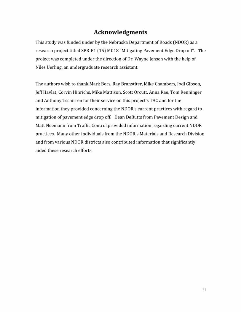
Acknowledgments This study was funded under by the Nebraska Department of Roads (NDOR) as a
research project titled SPR-P1 (15) M018 “Mitigating Pavement Edge Drop off”. The
project was completed under the direction of Dr. Wayne Jensen with the help of
Niles Uerling, an undergraduate research assistant.
The authors wish to thank Mark Bors, Ray Branstiter, Mike Chambers, Jodi Gibson,
Jeff Havlat, Corvin Hinrichs, Mike Mattison, Scott Orcutt, Anna Rae, Tom Renninger
and Anthony Tschirren for their service on this project’s TAC and for the
information they provided concerning the NDOR’s current practices with regard to
mitigation of pavement edge drop off. Dean DeButts from Pavement Design and
Matt Neemann from Traffic Control provided information regarding current NDOR
practices. Many other individuals from the NDOR’s Materials and Research Division
and from various NDOR districts also contributed information that significantly
aided these research efforts.

iii
Table of Contents Chapter 1 Introduction…………………………………………………………………………..…….. 1
1.1 Pavement Edge Drop Off …………………………………………………………....…… 1
1.2 Problems with Pavement Edge Drop Off ……………………………………….…… 3
1.3 Research Approach …………………………………………………………………............. 4
Chapter 2 Literature Search …………………………………………………………………….….. 5
2.1 Federal Guidelines .………………………………………………………………….…..…… 5
2.1.1 AASHTO Roadside Design Guidance..………………………..……..……. 5
2.1.2 Manual of Uniform Traffic Control Devices ……………………..……. 5
2.1.3 AASHTO Geometric Design of Highways and Streets…….…..…… 6
2.1.4 Federal Highway Administration ……………………………………..….. 6
2.1.5 Transportation Research Board ……………………………………..……. 7
2.2 Iowa Research ………………………………………………………………………….….…... 7
2.2.1 Liquid Polymer ……………………………………………………………...……. 8
2.2.2 Foamed Asphalt ……………………………………………………………..…… 9
2.2.3 Soybean Oil …………………………………………………………………..…….. 9
2.2.4 Portland Cement ……………………………………………………………..….. 9
2.2.5 Fly Ash, Recycled Concrete and Asphalt ……………………….…….. 10
2.2.6 Geogrid …………………………………………………………………….………. 10
2.2.7 Conclusions from the Iowa Study ……….…………………….………… 11
2.3 Texas Initiatives ……………………………………………………………….………….…. 11
2.3.1 Raw Edging …………………………………………………………………...….. 11
2.3.2 Edge Seal/Strip Seal …………………………………………………………... 12
2.3.3 Promoting the Growth of Desirable Vegetation …………………… 12
2.3.4 Edge Striping …………………………………………………………………..… 13
2.3.5 Reshaping Shoulders with On-Site Material ……………………..…. 13
2.3.6 Replenishing Pavement Edge with Select Borrow Material ….. 14
2.3.7 Edge (Lane) Widening ……………………………………………………….. 14
2.3.8 Buffalo Grass ……………………………………………………………………... 15
2.4 Other Initiatives ……………………………………………………………………………… 15
iv
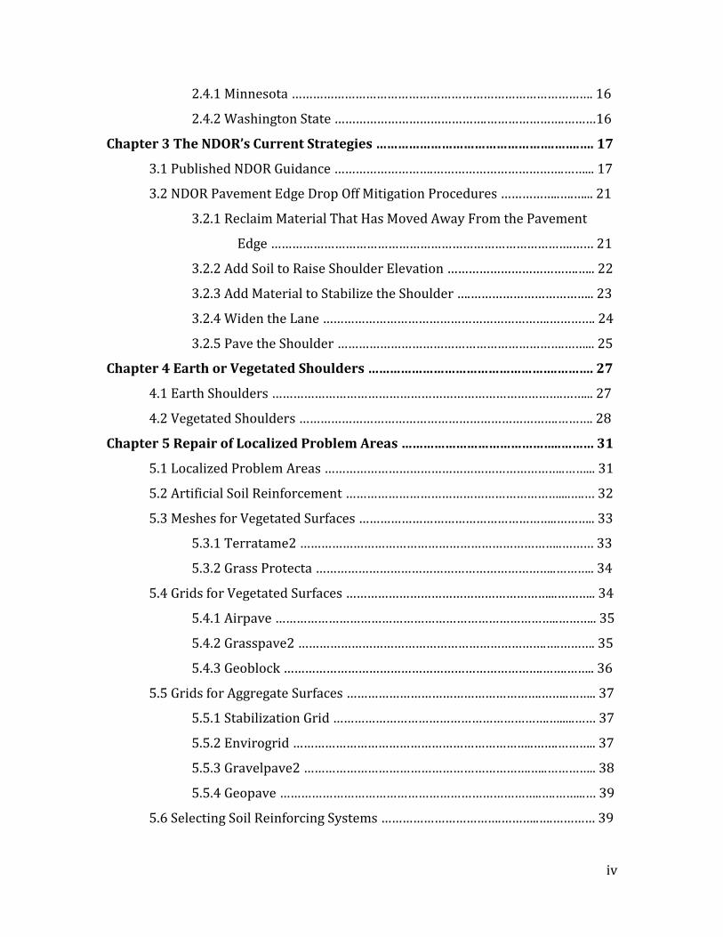
2.4.1 Minnesota …………………………………………………………………………. 16
2.4.2 Washington State …………………………………….………………….………16
Chapter 3 The NDOR’s Current Strategies ………………………………………….…….…. 17
3.1 Published NDOR Guidance ……………………….……………………………….……... 17
3.2 NDOR Pavement Edge Drop Off Mitigation Procedures ……………..….…... 21
3.2.1 Reclaim Material That Has Moved Away From the Pavement
Edge ………………………………………………………………………….…… 21
3.2.2 Add Soil to Raise Shoulder Elevation ……………………………….….. 22
3.2.3 Add Material to Stabilize the Shoulder ….…………………………….. 23
3.2.4 Widen the Lane ……………………………………………………….…………. 24
3.2.5 Pave the Shoulder ……………………………………………………….……... 25
Chapter 4 Earth or Vegetated Shoulders …………………………………………….………. 27
4.1 Earth Shoulders ……………………………………………………………………….……... 27
4.2 Vegetated Shoulders ……………………………………………………………….………. 28
Chapter 5 Repair of Localized Problem Areas ……………………………………..……… 31
5.1 Localized Problem Areas …………………………………………………………..……... 31
5.2 Artificial Soil Reinforcement ……………………………………………………....….… 32
5.3 Meshes for Vegetated Surfaces ………………………………………………..……….. 33
5.3.1 Terratame2 ………………………………………………………………..……… 33
5.3.2 Grass Protecta …………………………………………………………..……….. 34
5.4 Grids for Vegetated Surfaces …………………………………………………...……….. 34
5.4.1 Airpave ……………………………………………………………………..……….. 35
5.4.2 Grasspave2 …………………………………………………………….….………. 35
5.4.3 Geoblock ……………………………………………………………….…….…….. 36
5.5 Grids for Aggregate Surfaces ……………………………………………….……..…….. 37
5.5.1 Stabilization Grid …………………………………………………….….....…… 37
5.5.2 Envirogrid …………………………………………………………..…….……….. 37
5.5.3 Gravelpave2 ……………………………………………………….…..………….. 38
5.5.4 Geopave ………………………………………………………………..….……...… 39
5.6 Selecting Soil Reinforcing Systems …………………………….………..….………… 39

v
Chapter 6 Recommendations ………………………………………….………………….…..……43
6.1 Research Focus and Limitations ………………………….…………….….……….…. 43
6.2 Suggestions for Additions to the NDOR’s Publications ………….……..…….. 43
6.3 Suggestions for Future Research ……………………………….……….………..…… 44
6.4 Conclusions ……………………………………………………………………….….……….... 45
References ………………………………………………………………………………………………….. 46

vi
List of Figures Figure 1 – Exhibit 8.3a Typical Shoulder Construction (Uncurbed Section) ……….. 18
Figure 2 – Exhibit 8.3b Typical Shoulder Construction (Curbed Section) ………….... 19
Figure 3 – Shoulder Retriever Behind Tractor ………………………………………………….. 22
Figure 4 – NDOR District Maintenance Crews Adding Soil to Shoulder ……………… 23
Figure 5 – Concrete Millings Incorporated into Shoulder on NE 66 …………………… 24
Figure 6 – 12-Foot-Wide Lanes on 14-Foot-Wide Pavement (NE 41 West
of Wilber) …………………………………………………………………………………. 25
Figure 7 – Paved Shoulders on NE 61 South of Ogallala, NE ………………………………. 26
Figure 8 – Rumble Strips on Shoulder (US 77 south of Beatrice) ……………………….. 26
Figure 9 – Landscape Regions of Nebraska ………………………………………………………. 27
Figure 10 – Mean Annual Precipitation in Nebraska …………………………………………. 29
Figure 11 – Suggested Highway Shoulder Seed Mixture for the Sandhills ………….. 30
Figure 12 – Terratame2 …………………………..……………………………………………………… 33
Figure 13 – Grass Protecta ……………………………..……………………………………………….. 34
Figure 14 – Airpave Cross Section …………………………………………………………………… 35
Figure 15 – Grasspave2 Showing Infill Material ……………………………………………….. 36
Figure 16 – Geoblock Porous Pavement with Sod ……………………………………….……. 36
Figure 17 – Stabilization Grid Partially Filled ………………………………………….……….. 37
Figure 18 – Envirogrid Used as a Road Base ……………………………………………………. 38
Figure 19 – Driveway Constructed with Gravelpave2 ……………………………………… 38
Figure 20 – Constructing Parking with Geopave ……………………………………………… 39
Figure 21 – Grids for Vegetated Shoulders ……………………………………………………… 40
Figure 22 – Grids for Aggregate Shoulders ……………………………………………………… 41
Figure 23 – Recommended Base Course and Infill Materials ……………………………. 42
Figure 24 – The FHWA’s Safety Edge ………………………………………………………………. 43

vii
List of Tables Table 1 – Problematic Locations for Pavement Edge Drop Off ………………………….. 31
Table 2 – Artificial Soil Reinforcement Systems ………………………………………………. 40
1
Chapter 1 Introduction
1.1 Pavement Edge Drop Off
The shoulders adjacent to traveled lanes are critical components of overall
highway structure. Shoulders provide lateral support for the pavement, a place for
vehicles to pull over during emergencies, a recovery area when a vehicle’s wheel
leaves the pavement and (in many states) increased width to accommodate oversize agricultural equipment.
Pavement edge drop off is the vertical elevation difference between the
pavement’s surface and the adjacent shoulder surface. Pavement edge drop off
occurs on highways with both paved and unpaved shoulders. Edge drop off
between a paved lane and an unpaved shoulder often results from lack of shoulder
maintenance or from resurfacing a lane without a proper transition being created
between the paved lane and its shoulder. Vehicle wheels leaving the edge of the
pavement and erosion of unconsolidated and/or unstabilized shoulder material by
wind and water also create significant pavement edge drop off.
The underlying cause of pavement edge drop off is displacement of shoulder
material by one or more forces, creating a depression (drop off) adjacent to the
pavement’s edge. The extent to which shoulder material is displaced (by wheels,
wind or water) is dependent upon its composition. Composition of shoulder
material varies widely from one location to another. Some materials are more
resistant to deformation and movement than others.
Unstabilized earth is the most common type of shoulder material displaying
significant pavement edge drop off. Unstabilized earth shoulders exist where turf or
vegetation has not been established due to inadequate time, precipitation, sunlight,
or soil conditions/nutrients. When unstabilized earth shoulders become saturated
by precipitation, the soil within often becomes incapable of supporting wheel loads.
When a wheel strays off the pavement onto an unstabilized earth shoulder where
the shoulder material is saturated by runoff or precipitation, the wheel creates a rut
along the edge of the pavement.
2
Settlement of shoulder material along a pavement’s edge can also create
pavement edge drop off. Settlement is usually relatively uniform and occurs over a
period of years. Settlement can be mitigated significantly by establishing and
adhering to shoulder compaction standards during highway construction and
resurfacing. Shoulders can be treated as embankments (or subgrades) and
compacted to similar standards. Adequate shoulder compaction will eliminate
much of the magnitude of uniform settlement along pavement edges.
Wind and water erosion is another problem along highways with
unstabilized earth shoulders. Although pavements are somewhat porous, most are
porous enough to pass only very small amounts of water to the soil beneath. Almost
all precipitation events result in water flowing across the pavement’s surface onto
the shoulders. Significant rainfall is not required to generate significant quantities
of runoff when water accumulates across one or two lanes of pavement. Runoff
flows downhill across or along pavement until it reaches a low point, where it
begins to move away from the road. Unstabilized earth shoulders, composed of
lightly compacted or non-compacted in-situ material, lack a redundant source of
stability such as vegetation or aggregate to hold soil particles in place. Runoff
flowing parallel to pavement edges can transport considerable quantities of
material, creating significant edge drop off.
Pavement edge drop off can be particularly annoying and is often more
prevalent along narrow two-lane roads with unpaved shoulders that carry heavy
truck traffic. Trucks displace shoulder material during dry weather by slipstream
erosion. Trucks also disturb shoulder material by traveling with one (or more)
wheel(s) overhanging the pavement’s edge, particularly along the inside of curves.
Shoulder material is highly susceptible to displacement by vehicles with a wheel off
the road, especially during wet weather.
Common types of highway shoulders include concrete paved, bituminous
paved, bituminous (or other) surface treated, stabilized aggregate (a compacted
thickness of specified material), aggregate surfaced (a surface layer of gravel or
crushed stone) and vegetated or unstabilized earth. Unstabilized earth, vegetated
and aggregate surfaced shoulders are initially less expensive to construct than
3
paved shoulders, but are far more expensive to maintain. This study focused
primarily on pavement edge drop off mitigation for unstabilized earth and vegetated
shoulders.
1.2 Problems with Pavement Edge Drop Off
Accidents on two-lane undivided highways accounted for almost 60% of total
US traffic fatalities in 2006 (AASHTO, 2008). Conditions along the shoulder adjacent
to the pavement edge have been identified as a primary cause of many of these
accidents. Significant vertical drop off along the pavement edge becomes dangerous
when a vehicle’s wheel unexpectedly leaves the pavement. The surprised driver
attempts to turn the wheel and steer his/her vehicle back onto the highway. The
raised edge of pavement hinders the vehicle from easily reentering, forcing the
driver to apply additional force on the steering wheel. This can result in the vehicle
(1) moving abruptly across the travel lanes and colliding with a vehicle traveling in
the opposite direction or colliding with roadside hazards on the opposite side of the
roadway, (2) overturning on the roadway or roadside, or (3) colliding with roadside
hazards on the side of the road along its original direction of travel (Glennon, 2005).
The ability of a driver to recover from an encounter with pavement edge
drop off is a function of the vehicle’s speed, the shape and height of the drop off, the
width of the lane available for recovery and the driver’s training and experience.
Hallmark et al. (2006) reviewed driver’s licensing manuals from 49 states and found
that 32 contained advice to drivers about how to react when a vehicle’s wheels leave
the pavement edge. Advice can generally be summarized as follows: 1. Don’t panic;
2. Grip the steering wheel tightly; 3. Slow down without braking hard; and 4. Return
wheels to the pavement at slow speed. Only five states listed a recommended speed
of travel when attempting to steer the vehicle’s wheels back onto the pavement.
This varied from 15 mph in Delaware to almost stopped in Colorado (Hallmark, et
al., 2006).
Shoulder drop off is among the most cited accident-related highway
conditions and is a common source for tort claims against state transportation
agencies (Glennon, 2005). Substantial debate has occurred about what minimum

4
magnitude constitutes hazardous pavement edge drop and what responsibility state
DOTs have for minimizing pavement edge drop off and/or warning drivers of its
existence. This topic remains the subject of considerable discussion in courtrooms
across the nation and research by institutions of higher learning.
1.3 Research Approach
Multiple perspectives exist on pavement edge drop off and when or how it
should be prevented or mitigated. Pavement edge drop off can be alleviated by
using appropriate methods and procedures during design, construction and/or
maintenance and repair. The Nebraska Department of Roads (NDOR) is actively
committed to alleviating pavement edge drop off through development and use of
appropriate and cost effective methods during all phases of design, construction and
operation. This research study focused on documenting methods and procedures
used successfully by the NDOR districts and other states with the goal of
consolidating agency knowledge for dissemination to district personnel across the
entire State.

5
Chapter 2
Literature Search 2.1 Federal Guidelines
This section summarizes federal guidelines addressing the problem of
pavement edge drop off. While several agencies provide guidelines addressing this
subject, there appears to be no agreed-upon national standard concerning the
magnitude of pavement edge drop off which requires some form of remedial action.
Considerable advice is offered, some of it conflicting, concerning appropriate
thresholds where motorists should be warned about pavement edge drop off
conditions.
2.1.1 AASHTO Roadside Design Guidance
Chapter 9 of the Roadside Design Guide (AASHTO, 2002) discusses control
devices, barriers and safety features in construction work zones. The guide states
“no vertical drop off greater than 50 mm (2 inches) should occur”. It further states
that pavement edge drop off greater than 75 mm (3 inches) should not be allowed to
remain overnight. Mitigation procedures discussed include placing a temporary
wedge along the drop off, installing portable barriers to restrict traffic flow or using
traffic channelizing devices to create a buffer along the edge of the drop off.
2.1.2 Manual on Uniform Traffic Control Devices
This manual contains national standards for installing and maintaining traffic
control devices. Guidance specific to pavement edge drop off discusses signage
requirements recommended when edge drop off occurs, both in temporary and
permanent situations. Pavement edge drop off is discussed in Chapter 2C, Warning
Signs and in Chapter 6F, Temporary Traffic Control Devices.
Chapter 2C recommends the use of warning signs to alert drivers to
unexpected conditions at the pavement’s edge when the condition is permanent.
When an elevation difference of three inches or less exists between the pavement
surface and the shoulder, a sign warning of “Low Shoulder” is suggested. When an

6
elevation difference of greater than three inches exists, the same sign or a warning
sign indicating “Shoulder Drop Off” is suggested. The above recommendations are
intended as guidance only and can be overruled by engineering judgment (AASHTO,
2004).
Chapter 6F discusses temporary traffic control in construction work zones.
Signage appropriate for drop off conditions in work zones is discussed Section
6F.42. Guidance is identical to that given in Chapter 2c where “Low Shoulder”
signage is recommended when edge drop offs are less than three inches and
“Shoulder Drop Off” signage is recommended when drop offs are in excess of three
inches.
2.1.3 AASHTO Geometric Design of Highways and Streets
This AASHTO design manual stresses that periodic maintenance is necessary
to maintain shoulder elevation that is near the pavement’s surface. It provides no
guidance on what level of edge drop off is acceptable or what level of edge drop off
begins to warrant shoulder maintenance. It states that unstabilized shoulders will
undergo consolidation over time, so the elevation of the shoulder will gradually
become lower than the elevation of the traveled way (AASHTO, 2001).
2.1.4 Federal Highway Administration (FHWA)
The FHWA publication, Standard Specifications for Construction of Roads and
Bridges on Federal Highway Projects, offers guidance concerning pavement edge
drop off in construction work zones only. It states that “Low Shoulder” warning
signs should be used where the edge drop off exceeds two inches. Where the edge
drop off exceeds four inches, warning signs should be used and a 1:3 safety
(beveled) edge should be constructed along the pavement edge (FHWA, 2012a).
When bituminous pavement is being resurfaced, the FHWA recommends
installing a fillet (safety wedge) along the pavement edge adjacent to each shoulder.
The surface angle of the wedge should be inclined 30-35o from vertical to allow a
vehicle to reenter the driving lane without the driver having to overcompensate
(FHWA, 2012b). Placing new aggregate against the wedge flush with the pavement
7
surface eliminates the potential for edge drop off. The fillet adds minimal cost to the
paving project but has the potential to significantly reduce the number and severity
of accidents caused by edge drop off. Although the fillet reduces the hazards
associated with edge drop off, it does not eliminate the need for regular shoulder
maintenance on unpaved shoulders.
2.1.5 Transportation Research Board (TRB)
TRB publications basically summarize the results of various studies
concerning how levels of pavement edge drop off affect highway safety and
influence the severity and probability of vehicular crashes. Some contain
information about the effects of pavement edge drop off on safety in construction
work zones (Ivey et al., 1988) while others focus on the effects of pavement edge
drop off during post-construction highway operations (Glennon, 1985).
Studies have shown that a statistically significant relationship exists between
the frequency of pavement edge drop off related vehicle crashes and the magnitude
of pavement edge drop off when drop off is equal to or exceeds 2.5 inches (Hallmark
et al., 2006). Numerous states have established their threshold to begin repair or
maintenance work when pavement edge drop off exceeds 2 inches (White et al.,
2007), which seems prudent and provides a small margin of safety.
2.2 Iowa Research
Other states have conducted significant research on mitigating and repairing
pavement edge drop off, with the States of Iowa and Texas among the leaders in
published material. Iowa has tested a wide array of materials and methods in an
attempt to alleviate both pavement edge drop off and shoulder rutting on a variety
of shoulder types. Research on stabilization of granular shoulders in Iowa was
investigated specifically to determine if procedures had been developed that could
be adapted to stabilize highway shoulders in the Nebraska Sandhills.
A study completed in 2008 attempted to develop strategies for mitigating
pavement edge rutting problems using various combinations and gradations of
granular materials and soil stabilizing agents (Jahren et al., 2011). Calcium chloride,

8
magnesium chloride, Base One® and DUSTLOCK® were employed as soil
stabilization agents. Calcium chloride, magnesium chloride and Base One® did not
provide noticeable improvement (Jahren et al., 2011). DUSTLOCK appeared to
work well in locations where the underlying subgrade provided a stable base.
Iowa State University (ISU) conducted research which examined six methods
of stabilizing aggregate shoulders to mitigate edge drop off (White, et al., 2007). Six
locations along Iowa highways were selected to test chemical and mechanical
stabilization products designed to hold granular shoulder material in place. The
stabilization products tested included:
1. Liquid Polymer topically applied to a silty-gravel shoulder material.
2. Foamed asphalt over 12” full-depth shoulder reclamation with 3-4% class C
fly ash added (wet subgrade problem).
3. Soybean Oil emulsion applied to silty sand shoulder material by spray bar.
4. Portland cement mixed and compacted into silty sand shoulder material.
5. Fly Ash subgrade (6”) with 50% asphalt/ 50% concrete top layer.
6. Geogrid on sandy clay granular material placed at the interface between the
subgrade and granular aggregate layer above.
2.2.1 Liquid Polymer
Liquid polymer was tested on a section of pavement that had experienced
1.5-3” of rutting adjacent to the pavement edge before application. The liquid
polymer was applied as a 6-12” wide strip to a thickness of ½” adjacent to the
pavement edge. The polymer strip became detached from the pavement edge under
the impact of traffic and showed signs of delamination after only 30 days. Shoulder
material stabilized with liquid polymer began to disintegrate after soaking in water
for four hours, indicating poor stability under wet conditions. The liquid polymer
was characterized as performing inadequately as a soil stabilization agent on
highway shoulders by this study.

9
2.2.2 Foamed Asphalt
Soil mixing equipment was used to mix fly ash and fine aggregate into the
shoulder material to a depth of twelve inches. The mixture was then compacted
using a vibratory pad-foot roller followed by a smooth-wheel roller. Foamed
asphalt was subsequently placed over the compacted subgrade material.
The foamed asphalt improved the compressive strength of the shoulder
adjacent to the pavement edge by only 20%. However, significant edge drop off
and rutting were observed on the test section after eight months. Foamed
asphalt was judged to be useful only as a short-term solution, as this material
showed no permanence with regard to mitigating edge drop off or rutting.
2.2.3 Soybean Oil
Commercial emulsions were used to simplify application of soybean oil to
pavement shoulders. Problems were encountered with the oil separating from
water in the emulsion during application, which plugged the distributor. A two-
foot wide by six-inch deep section of shoulder 340 feet in length was stabilized
using various soybean emulsions.
After soybean oil had been applied to the shoulder subgrade using a
spray bar, an additional six inches of crushed rock was placed on top, bladed and
then compacted. Soybean oil proved unsuccessful in mitigating the formation of
ruts along the pavement edge. Ruts three inches deep were observed along the
pavement edge after only eight months. Performance of soybean oil as a soil
stabilization agent varied significantly depending on which commercial product
was being tested, but overall soybean oil was not considered to be successful as
a mitigating agent for pavement edge drop off.
2.2.4 Portland Cement
Well-graded sand with silt shoulder material was mixed and then
compacted with 10% Portland cement and water to a depth of six inches. The
resulting mixture was subsequently sealed using a pad foot roller.

10
Four months after placement, significant wash-boarding and lateral
erosion were observed along this shoulder section. At that time, pavement edge
drop off averaged about one inch. Eight months after placement of the Portland
cement-shoulder material mix, edge drop off had increased to an average of
three inches. Cement stabilization was not considered successful in mitigating
pavement edge drop off.
2.2.5 Fly Ash, Recycled Concrete and Asphalt
The first step in this shoulder reconstruction was to mix 15-20% fly ash
into the upper twelve inches of clay subgrade. The subgrade was then
compacted using a pad foot roller. On top of the compacted subgrade, a six-inch
layer of 50% concrete/50% recycled asphalt millings was placed and compacted
using a smooth wheel roller.
The fly ash subgrade stabilization with a compacted aggregate surface
layer was considered successful in mitigating both short and long term
pavement edge drop off as well as rutting. Little to no pavement edge drop off or
rutting was noted after one year. A comparison section with an identical
subgrade where six inches of crushed limestone was used as the surface layer
achieved similar results.
2.2.6 Geo-grid
Geo-grid was installed between a compacted subgrade and six inches of
compacted, granular surface material. Three different types of Tensar geo-grids
were tested, with their cost varying from $1.50-$3.50/yd2.
The control section, which contained no geo-grid, began developing
rutting adjacent to the pavement edge within 30 days. Little to no pavement
edge drop off in sections where geo-grid was installed had occurred after one
year. All three types of geo-grid provided significant improvement to the soft
foundation soil and were effective in preventing both rutting and pavement edge
drop off. Areas where the geo-grid had been exposed to weathering (uncovered

11
by a snow plow) showed more rutting and pavement edge drop off than areas
where the geo-grid remained entirely covered by aggregate.
2.2.7 Conclusions from the Iowa Study
Of the six strategies tested, only two were considered to be successful.
These two, fly ash stabilization and geo-grid stabilization of the subgrade, both
require removal of existing shoulder material, emplacement of select
replacement material(s) in layers and compaction. While these strategies work
well as permanent solutions to the problem of pavement edge drop off, they are
currently too expensive to be used for stabilizing shoulders on most roads in the
Nebraska Sandhills.
Fly ash stabilization of shoulder material could most economically be
employed in conjunction with either major highway reconstruction or
resurfacing operations. The high cost of geo-grid stabilization makes it useful for
shoulder stabilization mostly on high traffic volume roads. However, geo-grid
stabilization, applied on a much smaller scale, may be appropriate for making
repairs to small sections of shoulder plagued by locally induced problems.
2.3 Texas Initiatives
The Texas Department of Transportation (TxDOT) embraces a wide
range of maintenance and repair activities designed to decrease the rate of
pavement edge deterioration and to mitigate pavement edge drop off. A brief
description of activities thought by researchers to be most applicable to
adoption for use in Nebraska follows.
2.3.1 Raw Edging
Sealing transverse cracks that begin at the edge of the pavement and
progress inward is known as “raw edging”. This procedure is normally
performed by TxDOT in-house maintenance personnel and is charged against
the maintenance function code for fog sealing. Raw edging involves spraying a
liquid asphalt material along the pavement edge, generally covering somewhere

12
between one and two feet of pavement. The most common types of spray
solution include asphalt emulsions or cutbacks. The spray width is often
centered on the pavement edge, so the spray pattern includes 50% of the
pavement surface and 50% of the unpaved soil along the pavement edge. When
done in this manner, raw edging confers a degree of resistance to shoulder
erosion from wind and light rain. Some districts distribute a thin layer of fine
sand over the initial spray pattern to prevent stickiness. Raw edging is often
done after other forms of edge repair as preventative maintenance.
This process extends the lifespan of asphalt pavement and retards
raveling of aggregate along the pavement’s edge. It also helps to seal the
pavement edge to prevent damage from water infiltration (Lawson and Hossain,
2004).
2.3.2 Edge Seal/Strip Seal
Edge seal or strip seal is another common preventative maintenance
procedure used on asphalt pavement edges in Texas. This practice involves
spray application of a single layer of binder (emulsion or cutback) followed by
immediate application of a thin layer of aggregate which is then rolled. The
process is commonly done on a one to two foot wide strip along the outer edge
of the pavement.
This process is similar to raw edging but it generally extends over a larger
area and includes the addition (and rolling) of aggregate. The main concern with
repeatedly using this procedure is a buildup of aggregate along the pavement’s
outer edge, which can inhibit water from draining freely off the pavement’s
surface (Lawson and Hossain, 2004).
2.3.3 Promoting the Growth of Desirable Vegetation
Vegetation along a roadway’s shoulders is beneficial, as it controls both
wind and water erosion of shoulder material. A well-developed root system
along a roadway also helps to support and stabilize the pavement’s edge.
Roadside vegetation must ultimately be maintained by natural precipitation. In
13
the eastern one-third of Texas (as in the eastern one-third of Nebraska), rich soil
and adequate rainfall is usually sufficient to establish and maintain successful
roadside vegetation. In the western two-thirds of Texas (as in the western two-
thirds of the Nebraska), the sparse rainfall and sandy soil make establishment of
good vegetative cover challenging and sometimes impossible.
In the eastern one-third of Texas, maintenance personnel try to promote
vegetation growth during scheduled repair and maintenance processes (Lawson
and Hossain, 2004). Many districts rely upon native processes to reseed the
disturbed soil, while others sow native or Buffalo grass along highway shoulders
as the last step of rehabilitation or repair.
Establishment of vegetation is often included in TxDOT’s construction
contracts for road repair and maintenance projects. EPA regulations for storm
water pollution prevention plans (SWPPP) require that 70% of the original
roadside vegetation be re-established before the contractor can be relieved of
responsibility for maintaining the roadside. This requirement can present a
major challenge for a contractor repairing roads in West Texas.
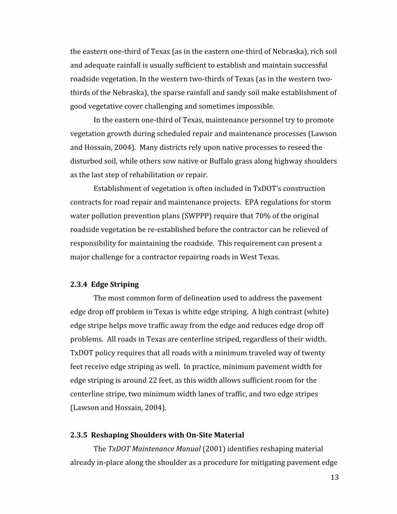
2.3.4 Edge Striping
The most common form of delineation used to address the pavement
edge drop off problem in Texas is white edge striping. A high contrast (white)
edge stripe helps move traffic away from the edge and reduces edge drop off
problems. All roads in Texas are centerline striped, regardless of their width.
TxDOT policy requires that all roads with a minimum traveled way of twenty
feet receive edge striping as well. In practice, minimum pavement width for
edge striping is around 22 feet, as this width allows sufficient room for the
centerline stripe, two minimum width lanes of traffic, and two edge stripes
(Lawson and Hossain, 2004).
2.3.5 Reshaping Shoulders with On-Site Material
The TxDOT Maintenance Manual (2001) identifies reshaping material
already in-place along the shoulder as a procedure for mitigating pavement edge

14
drop off. This method consists of using equipment (most commonly a motor
grader) to pull materials from down the shoulder slope back up to the
pavement’s edge. Material is then compacted by equipment tires or by a
pneumatic tire roller as part of the reshaping process.
Reshaping shoulders has become quite common in Texas as minimum
personnel and equipment required consist of one man and a grader. Reshaping
is a very quick and inexpensive method of mitigating pavement edge drop off.
However, reshaping may be effective for only a few weeks up to a year under
optimal conditions. Adjusting the moisture content of the soil and applying a
minimum level of compaction can extend the life of this repair procedure by up
to three years (Lawson and Hossain, 2004).
2.3.6 Replenishing Pavement Edge with Select Borrow Material
Replenishing the pavement edge with select borrow material is similar to
reshaping shoulders except new material must be added to the shoulder. New
material can consist of reclaimed asphalt pavement (RAP), concrete or asphalt
millings, or other select borrow materials. Typical steps when replenishing
pavement edge material includes surface preparation, delivering and spreading
borrow material(s), compaction and surface sealing (Lawson and Hossain,
2004). Compaction specifications for this type of repair vary. In many instances
compaction is applied using only wheels of equipment already on-site.
Replenishing a pavement’s edge requires traffic control personnel plus a
crew of equipment operators (grader, borrow trucks, water trucks and roller)
and at least one person controlling deposition of the borrow material along the
pavement edge. The effectiveness and durability of this procedure is a function
of the effort expended and quality of borrow materials used.
2.3.7 Edge (Lane) Widening
Lawson and Hossain (2004) make the claim that lane widening is the
ultimate solution for pavement edge repair problems. This strategy is based
upon the observation that narrow lanes lacking shoulders, in combination with

15
moderate traffic loads and local environmental factors, create an environment
where pavement edge drop off occurs more frequently. An example cited is the
Houston district, where most of the edge maintenance procedures during the
past seven years consisted of installing narrow (two feet wide), paved shoulders.
Most accidents attributed to pavement edge drop off problems in the Houston
District now result from deliberate or illegal activities (Lawson and Hossain,
2004). Examples of where narrow paved shoulders have reduced pavement
edge drop off problems in Georgia and Pennsylvania are also cited.
Edge widening can be completed as part of a larger rebuild, rehabilitation
or construction effort. Upgrading the traveled way width to a minimum of
twenty-six feet has become the customary TxDOT standard for pavement
reconstruction projects (Lawson and Hossain, 2004). TxDOT also regularly lets
both construction and maintenance contracts to add two feet of width on both
sides of narrow but otherwise serviceable highways.
2.3.8 Buffalo Grass
Researchers at Texas Transportation Institute found that Buffalo grass,
which is extremely hardy, requires no water (other than natural precipitation)
and little maintenance, can be very effective when used to stabilize highway
shoulders. Buffalo grass is naturally adapted to dryland conditions on prairies
and plains and new varieties have been developed that extend its natural area of
adaption. It is less invasive of asphalt pavement structure and requires less
water than to hold soil together than many other grasses (TTI, 1996). Buffalo
grass matures at a rate competitive with fast growing weeds, but because of its
low density, stands of Buffalo grass often become weedy.
2.4 Other Initiatives
Many other states are experimenting with various methods and
procedures to mitigate pavement edge drop off. Most currently employed
methods and procedures are similar to those already discussed. Two additional
16
examples are included here to illustrate that pavement edge drop off is being
addressed using a wide variety of techniques.
2.4.1 Minnesota
MNDOT routinely lets contracts for paving an additional two feet
beyond the point where edge striping will be placed on its major highways
(Shoulder Safety and Maintenance, 2009). The additional two feet of pavement
allows drivers of straying vehicles to recover while their wheels remain on
pavement, rather than having a wheel move onto an aggregate or earth shoulder.
Rumble strips are being experimentally incorporated into paved shoulders along
the outside edge of the white edge stripe to provide drivers with an acoustic
warning that a wheel is leaving the normal driving lane.
2.4.2 Washington State
Shoulder rumble strips are meant to warn drivers that they are
entering a portion of the roadway that is not intended for routine traffic use.
Washington State has experimented with installing shoulder rumble strips on
several sections of its interstates and US highways with paved shoulders.
Shoulder rumble strips installed on a 44-mile test section of I-82 in 1992
resulted in a 40% reduction in off-road vehicle crashes. A before-and-after
comparison evaluating 56 miles of pavement conducted on I-5, I-90 and US 395
showed a 35% reduction in off-road crashes after installation of shoulder
rumble strips (Washington State DOT, 2014).

17
Chapter 3
The NDOR’s Current Strategies 3.1 Published NDOR Guidance
The NDOR provides guidance for shoulder construction and maintenance in
both its Roadway Design Manual and in Specifications for Highway Construction.
Guidance in the Roadway Design Manual (NDOR, 2014) is included in Chapters 8
and 17. Chapter 8, Surfacing, contains the following information:
Shoulder Construction. The subgrade on all projects that have new
surfacing shall be designed an additional 0.2 ft (50 mm) high for
trimming. The excess material should be incorporated into the earth
shoulder as shown in Exhibits 8.3a and 8.3b. Soil material used for
shoulder construction must have the capability to support vegetation.
Sources of shoulder material include:
• Undercutting, leaving the grade high for use in shoulders after
the trimming operation.
• Excess excavation.
• Located sites within state right-of-way (station-to-station).
• Locations outside the state right-of-way (contractor’s
responsibility).
Exhibits 8.3a and 8.3b from the Roadway Design Manual are shown below as
Figure 1 and 2. Both figures show subgrade preparation extending a minimum of
three feet (0.9 m) outward from where the edges of the subgrade have been
prepared for paving. Thirty feet is thus the minimum subgrade preparation
required to accommodate two twelve-foot lanes of traffic. The extra three feet of
subgrade preparation on each side of the traffic lanes provides a stable platform on
which a stabilized aggregate, aggregate surfaced or paved shoulder can be
constructed.

18
Figure 1 – Exhibit 8.3a Typical Shoulder Construction (Uncurbed Section)

19
Figure 2 – Exhibit 8.3b Typical Shoulder Construction (Curbed Section)
The Roadway Design Manual also contains information on pavement
shoulders in Chapter 17 – Resurfacing, Restoration and Rehabilitation (3R) Projects.
Page 17-4, Safety Improvements, contains information in the ninth bullet from the
top, which reads:
A beveled edge is a sloped finish to the edge of pavement (both asphaltic
concrete and Portland Cement Concrete). The beveled edge will be
installed on rural high-speed (V > 50 mph) highways when:
1. The project includes 3 inches or greater of surfacing placement.
2. Surfaced shoulders are less than 6 feet in width, not including
segments of erosion control curbed shoulder.
3. The highway is not curbed.

20
4. At other project locations identified by Traffic as a mitigation
measure for crash history.
No specifications or details concerning composition or methods of construction for
the beveled edge are included.
Section 304, Earth Shoulder Construction, from Specifications for Highway
Construction (NDOR, 2007), contains additional information on shoulder
construction. Section 304.03, Construction Methods, includes:
4. a. (1) The contractor shall construct shoulders to the typical cross
sections shown in the plans.
(2) The shoulder shall be tight bladed using a motor grader to
remove any vegetation. The underlying subgrade shall be scarified to a
depth of 6 inches (150 mm) and then compacted with at least two
complete coverages over the area with an approved roller.
(3) Shoulder construction shall match the existing width and fill
slope or plan sections widths, whichever is widest.
This section contains no compaction specifications. No compaction of
shoulder material is appropriate for locations where rainfall is sufficient to establish
vegetated shoulders. Compaction generally inhibits but does not prevent eventual
establishment of vegetation on road shoulders.
Page 43 of the Pavement Design Manual (NDOR, 2013) contains a letter by
Robert Rae, an NDOR pavement engineer, discussing a widened in-place recycling
strategy for asphalt pavement. This strategy consists of placing milled asphalt in a
trench along the outer edges of each lane during mill-and-fill operations to minimize
grade rise when an asphalt overlay is applied over the milled surface. The total
overlaid width becomes twenty-eight feet, creating two fourteen foot lanes.
Advantages cited for this practice include:
1) Reduces duration of pavement edge drop off during paving operations.
2) Eliminates the need to borrow material for shoulder construction.
3) Pavement elevation increase is minimized.
4) Incidence of pavement edge drop off accidents should be reduced post-
construction because of wider lanes.

21
5) Wider lanes are better able to accommodate agricultural equipment.
6) Snow plowing is safer due to the increased surface area.
This strategy has been widely adopted by the NDOR districts and is currently being
used extensively for asphalt overlay operations.
3.2 NDOR Pavement Edge Drop Off Mitigation Procedures
The NDOR districts have developed several procedures for shoulder
maintenance and/or repair which significantly alleviate pavement edge drop off.
Some procedures work better than others under specific climatic conditions and
with particular types of soil. Some procedures are used only within a few NDOR
districts, while others are used across the entire state. These procedures include:
• Reclaim or redistribute aggregate or soil that has moved away from the
pavement edge.
• Add material (usually soil) to raise the shoulder elevation.
• Add aggregate or other materials to stabilize the shoulder.
• Widen the lane.
• Pave the shoulder.
3.2.1 Reclaim Material That Has Moved Away From The Pavement Edge
Wind, water and vehicle tires all move shoulder material away from
pavement edges. Material remains nearby, but it is not performing its intended
function. The NDOR has traditionally recovered this material by using a grader to
reshape the highway shoulder, moving material closer to the pavement edge.
A type of specialized equipment (referred to as a shoulder retriever) created
especially for this task is being used by District 3 in lieu of a grader. Figure 3 shows
a shoulder retriever being used to increase the elevation of the shoulder material
adjacent to the pavement. A shoulder retriever can be mounted on a tractor, grader,
or loader.

22
Figure 3 – Shoulder Retriever Behind Tractor.
This procedure involves minimal investment in equipment and personnel.
The task is usually performed by one maintenance worker operating a single piece
of equipment. Compaction is seldom applied unless some type of shoulder surfacing
procedure is scheduled to follow recovery of material.
3.2.2 Add Soil to Raise the Shoulder Elevation
Soil is commonly added to shoulders where settlement over time has
resulted in a fairly uniform edge drop off over an extended distance. Soil is
commonly transported to the site by truck and emplaced by mechanical equipment
before being smoothed with a blade (Figure 4). The graded soil will usually be
compacted if the shoulder is scheduled to be surfaced. Since obtaining and
transporting borrow material to the site is required, this procedure is more
complicated and more expensive than reclaiming material already on-site.
23
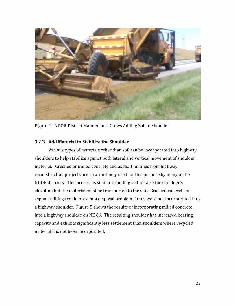
Figure 4 - NDOR District Maintenance Crews Adding Soil to Shoulder.
3.2.3 Add Material to Stabilize the Shoulder
Various types of materials other than soil can be incorporated into highway
shoulders to help stabilize against both lateral and vertical movement of shoulder
material. Crushed or milled concrete and asphalt millings from highway
reconstruction projects are now routinely used for this purpose by many of the
NDOR districts. This process is similar to adding soil to raise the shoulder’s
elevation but the material must be transported to the site. Crushed concrete or
asphalt millings could present a disposal problem if they were not incorporated into
a highway shoulder. Figure 5 shows the results of incorporating milled concrete
into a highway shoulder on NE 66. The resulting shoulder has increased bearing
capacity and exhibits significantly less settlement than shoulders where recycled
material has not been incorporated.

24
Figure 5 – Concrete Millings Incorporated into Shoulder on NE 66.
3.2.4 Widen the Lane
One of the most effective methods of reducing pavement edge drop off is to
widen the lanes. The enhanced safety afforded by paved shoulders can often be
achieved by paving only an extra two to three feet (Souleyrette et al., 2001). Figure
6 shows NE 41 west of Wilber where pavement width was increased to fourteen feet
through the NDOR’s recycling in-place strategy for bituminous pavement. Distance
from the center of roadway to the inner edge of the outside lane marking is twelve
feet. Nebraska may be partially realizing the benefits of paved shoulders from the
14-foot-wide lanes, where effectively a 2-foot-wide paved shoulder abuts each 12-
foot-wide lane. For highways with significant bicycle traffic, a minimum paved
shoulder width of four feet is desirable (Souleyrette et al., 2001).
Delineating a traffic lane’s outer edge with a white line mitigates pavement
edge drop off by providing a visual clue to the driver as the vehicle’s wheels begin
nearing the edge of the lane. The NDOR requires marking the outside edge of all
pavements ten or more feet in width with solid white lines five inches in width.
25
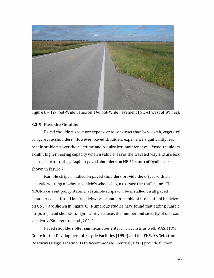
Figure 6 – 12-Foot-Wide Lanes on 14-Foot-Wide Pavement (NE 41 west of Wilber).
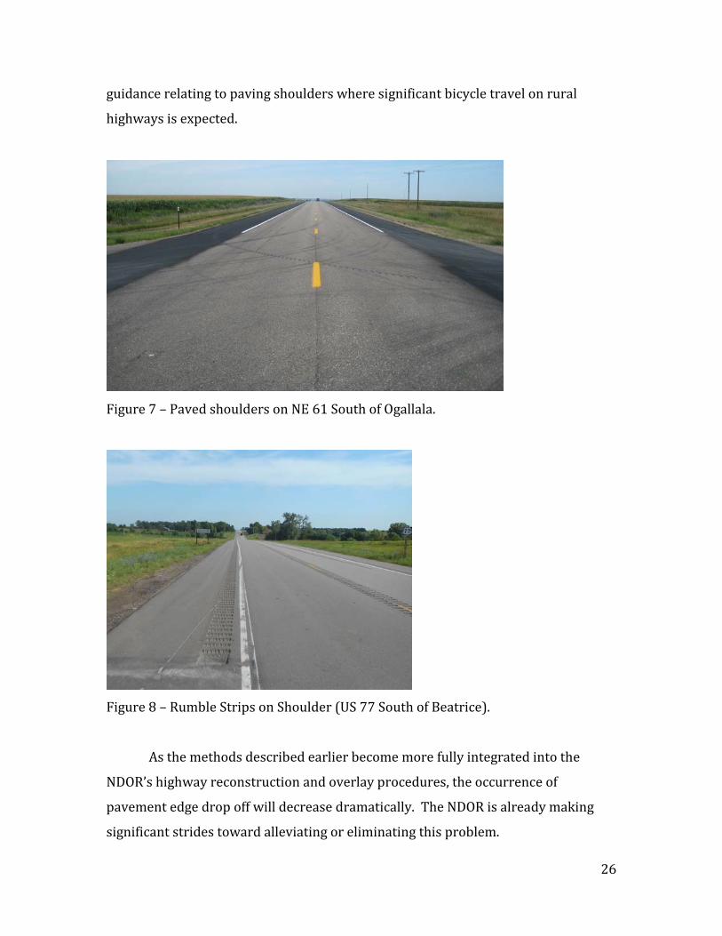
3.2.5 Pave the Shoulder
Paved shoulders are more expensive to construct than bare earth, vegetated
or aggregate shoulders. However, paved shoulders experience significantly less
repair problems over their lifetime and require less maintenance. Paved shoulders
exhibit higher bearing capacity when a vehicle leaves the traveled way and are less
susceptible to rutting. Asphalt paved shoulders on NE 61 south of Ogallala are
shown in Figure 7.
Rumble strips installed on paved shoulders provide the driver with an
acoustic warning of when a vehicle’s wheels begin to leave the traffic lane. The
NDOR’s current policy states that rumble strips will be installed on all paved
shoulders of state and federal highways. Shoulder rumble strips south of Beatrice
on US 77 are shown in Figure 8. Numerous studies have found that adding rumble
strips to paved shoulders significantly reduces the number and severity of off-road
accidents (Souleyrette et al., 2001).
Paved shoulders offer significant benefits for bicyclists as well. AASHTO’s
Guide for the Development of Bicycle Facilities (1999) and the FHWA’s Selecting
Roadway Design Treatments to Accommodate Bicycles (1992) provide further
26
guidance relating to paving shoulders where significant bicycle travel on rural
highways is expected.
Figure 7 – Paved shoulders on NE 61 South of Ogallala.
Figure 8 – Rumble Strips on Shoulder (US 77 South of Beatrice).
As the methods described earlier become more fully integrated into the
NDOR’s highway reconstruction and overlay procedures, the occurrence of
pavement edge drop off will decrease dramatically. The NDOR is already making
significant strides toward alleviating or eliminating this problem.

27
Chapter 4
Earth or Vegetated Shoulders 4.1 Earth Shoulders
A well-maintained shoulder has a sloped surface only slightly lower than the
adjacent highway’s driving surface. The shoulder elevation should be flush with the
pavement surface where the two meet and slope gently away from the paved lane.
Ideally the shoulder should not exhibit any abrupt changes in elevation (have
erosion problems) either longitudinally or transversely.
Shoulder surfaces can be as simple as bare earth. Composition of earth
shoulders varies from stabilized, compacted, select fill material to unmodified, in-
situ soil. Earth shoulders are the least expensive type of shoulders to construct, but
generally require more maintenance and repair than any other type due to erosion
of material by wind, water and the passage of vehicles.
The size of particles within and composition of earth shoulders varies with
geology and the landscape position (Figure 9). Unique problems with pavement
edge erosion are encountered where road shoulders are composed of relatively
uniform, unconsolidated material, such as soil found in the Sandhills.
Figure 9 - Landscape Regions of Nebraska.

28
The Sandhills (Region D in Figure 9) is a region of mixed-grass prairie
covering a large field of sand dunes in north-central Nebraska. This region was
formed by wind action across glacial outwash during the late Tertiary and Early
Pleistocene. Shoulders along highways in the Sandhills have proven to be highly
erodible. The relatively uniform particle size and absence of smaller particles
produce considerable void space within the soil and enable the shoulder to drain
extremely well. The absence of smaller particles, however, robs the soil of sufficient
internal cohesion to remain stable when buffeted by wind or water. When
emplacing material to support vehicular loads and to resist wind and water erosion,
not less than ten percent should pass the #200 sieve. The most economical solution
for prevention of erosion on this type of shoulders is to encourage the growth of
vegetation, which stabilizes shoulder material through root penetration.
4.2 Vegetated Shoulders
Vegetation is temporarily removed from road shoulders by construction
activities. Road shoulders sometimes remain without vegetation for long periods of
time because of the inability of vegetation to re-establish itself in a particular
climate or under adverse nutrient or light conditions.
Vegetation along a highway is beneficial to stabilization of the pavement
edges. It represents the most edge drop off resistant non-paved shoulder option
where precipitation is adequate to maintain it. Vegetation increases shoulder
stability in all climates and under all soil conditions due to its roots penetrating soil
layers and holding larger soil particles in place. The principle factor influencing
vegetation growth is rainfall. Rainfall is remarkably different across Nebraska,
varying from almost thirty-four inches annually in the southeastern corner of the
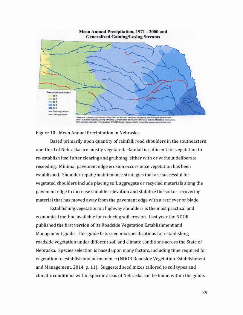
State to less than twelve inches annually along its far western border (Figure 10).
29
Figure 10 - Mean Annual Precipitation in Nebraska.
Based primarily upon quantity of rainfall, road shoulders in the southeastern
one-third of Nebraska are mostly vegetated. Rainfall is sufficient for vegetation to
re-establish itself after clearing and grubbing, either with or without deliberate
reseeding. Minimal pavement edge erosion occurs once vegetation has been
established. Shoulder repair/maintenance strategies that are successful for
vegetated shoulders include placing soil, aggregate or recycled materials along the
pavement edge to increase shoulder elevation and stabilize the soil or recovering
material that has moved away from the pavement edge with a retriever or blade.
Establishing vegetation on highway shoulders is the most practical and
economical method available for reducing soil erosion. Last year the NDOR
published the first version of its Roadside Vegetation Establishment and
Management guide. This guide lists seed mix specifications for establishing
roadside vegetation under different soil and climate conditions across the State of
Nebraska. Species selection is based upon many factors, including time required for
vegetation to establish and permanence (NDOR Roadside Vegetation Establishment
and Management, 2014, p. 11). Suggested seed mixes tailored to soil types and
climatic conditions within specific areas of Nebraska can be found within the guide.
30
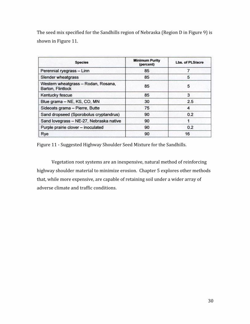
The seed mix specified for the Sandhills region of Nebraska (Region D in Figure 9) is
shown in Figure 11.
Figure 11 - Suggested Highway Shoulder Seed Mixture for the Sandhills.
Vegetation root systems are an inexpensive, natural method of reinforcing
highway shoulder material to minimize erosion. Chapter 5 explores other methods
that, while more expensive, are capable of retaining soil under a wider array of
adverse climate and traffic conditions.
31
Chapter 5
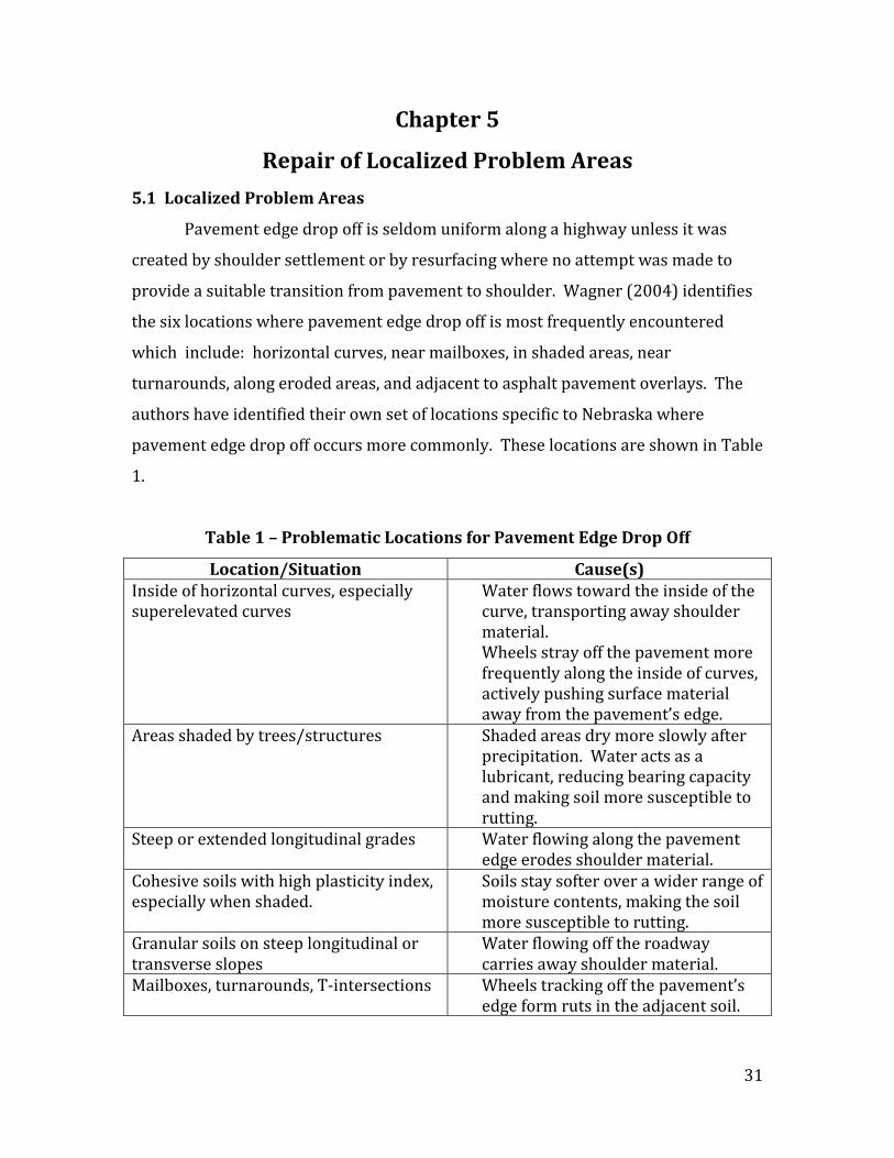
Repair of Localized Problem Areas 5.1 Localized Problem Areas
Pavement edge drop off is seldom uniform along a highway unless it was
created by shoulder settlement or by resurfacing where no attempt was made to
provide a suitable transition from pavement to shoulder. Wagner (2004) identifies
the six locations where pavement edge drop off is most frequently encountered
which include: horizontal curves, near mailboxes, in shaded areas, near
turnarounds, along eroded areas, and adjacent to asphalt pavement overlays. The
authors have identified their own set of locations specific to Nebraska where
pavement edge drop off occurs more commonly. These locations are shown in Table
1.
Table 1 – Problematic Locations for Pavement Edge Drop Off
Location/Situation Cause(s) Inside of horizontal curves, especially superelevated curves
Water flows toward the inside of the curve, transporting away shoulder material. Wheels stray off the pavement more frequently along the inside of curves, actively pushing surface material away from the pavement’s edge.
Areas shaded by trees/structures Shaded areas dry more slowly after precipitation. Water acts as a lubricant, reducing bearing capacity and making soil more susceptible to rutting.
Steep or extended longitudinal grades Water flowing along the pavement edge erodes shoulder material.
Cohesive soils with high plasticity index, especially when shaded.
Soils stay softer over a wider range of moisture contents, making the soil more susceptible to rutting.
Granular soils on steep longitudinal or transverse slopes
Water flowing off the roadway carries away shoulder material.
Mailboxes, turnarounds, T-intersections Wheels tracking off the pavement’s edge form ruts in the adjacent soil.

32
Methods of alleviating edge drop off in small areas can be very different from
methods used to mitigate edge drop off along extended sections of highway. One of
the most practical methods of treating edge drop off in localized areas is the
addition of some type of artificial soil reinforcement to the problem shoulder.
5.2 Artificial Soil Reinforcement
Artificial soil reinforcement is basically of two types, mesh and grid. Mesh
has a very limited vertical cross-section. Its thickness is often measured in
millimeters. Mesh was originally conceived and created as a membrane to separate
different layers of soil. It is typically used for reinforcement of soil in retaining
walls, steepened slopes, embankments, and waste containment facilities.
Mesh is composed of high molecular weight multifilament yarns coated with
PVC and woven into a stable network. It is very resistant to biological degradation
and to attack from naturally occurring chemicals and soil conditions. Mesh limits
downward movement of aggregate larger than the size of the mesh openings, which
creates a layer of soil more resistant to penetration (i.e. rutting). Mesh is sometimes
used without an aggregate layer but this practice does not confer the same
resistance to rutting as use of mesh with an aggregate layer provides.
Grid is three-dimensional soil reinforcement which creates a composite layer
of material having increased strength. Vertical depth of the grid can vary from a
minimum of about one inch to a maximum of eight inches or more. Greater depth
makes placement of infill material more difficult. Infill material is typically select
aggregate, although gravel, sand and many different types of soil have all been used
successfully under varying conditions. Grids reinforce soil by confining infill
material within a three-dimensional framework. Spreading of the infill material
under load is prevented by the grid’s honeycomb structure. The composite layer
created by the grid distributes concentrated wheel loads across a larger area of
subgrade beneath, which prevents rutting.
Many different types and sizes of meshes and grids are available from a wide
variety of manufacturers. Most meshes and grids are patented; many are
trademarked. Meshes and grids are commonly employed to control soil erosion on

33
slopes, stabilize vegetation or aggregate for overflow and temporary parking lots, to
stabilize soil beneath fire and utility lanes as well as to improve the bearing capacity
of cart paths and driveways. Some commercially available meshes and grids
specifically used to mitigate rutting caused by automobile and emergency vehicle
wheel loads are discussed in the remainder of this chapter.
5.3 Meshes for Vegetated Surfaces
Mesh is used almost exclusively to reinforce vegetated surfaces, since mesh
has minimal vertical cross-section and thus has limited ability to laterally contain
material within its openings. Mesh only partially decreases penetration by wheel
loads due to its tensile strength, so it is used to mitigate rutting only where rutting
does not constitute a serious problem .
5.3.1 Terratame2
Terratame2 is a woven polyethylene mesh that was originally developed for
control of scour in highly erosive locations. It is widely used for scour protection
below culvert outlets and for erosion control on slopes and in ditches. Terratame2
has been used in traffic applications primarily to reinforce unstable soils in
temporary and permanent grass parking lots. Terratame2 is placed over a seeded
or sodded soil surface. Vegetation grows up and through the mesh structure.
Figure 12 shows Terratame2 being unrolled to create a parking lot.
Figure 12 – Terratame2.

34
5.3.2 Grass Protecta
Grass Protecta is a polyethylene mesh that is also available in 2 m x 20 m
rolls (Figure 13). It was originally developed for reinforcing soft soils beneath fire
and utility lanes, but its uses have evolved to include reinforcement of soil beneath
temporary and recreational vehicle parking lots, aircraft taxiways, helicopter
landing pads and recreational trails. Grass Protecta can be installed directly over
existing grass by cutting the grass short, unrolling the mesh and securing the mesh
to the existing surface with metal or plastic pins. Grass Protecta protects, reinforces
and stabilizes grass against damage caused by traffic (both pedestrian and
vehicular). It has been found to be especially effective in minimizing rutting on
muddy surfaces. Grass Protecta is actively marketed for use as grass shoulder
reinforcement along highways.
Figure 13 – Grass Protecta.
5.4 Grids for Vegetated Surfaces
Grids are more versatile than meshes because a grid can be used to reinforce
either vegetated or aggregate surfaces. Common thicknesses of grids used to
reinforce vegetated surfaces vary from one to two and one-half inches. The three-
dimensional structure of a grid retains soil or aggregate particles and creates a
stable layer of composite material within the overall soil structure. This stable layer
increases the bearing capacity of the soil and decreases rutting.
35
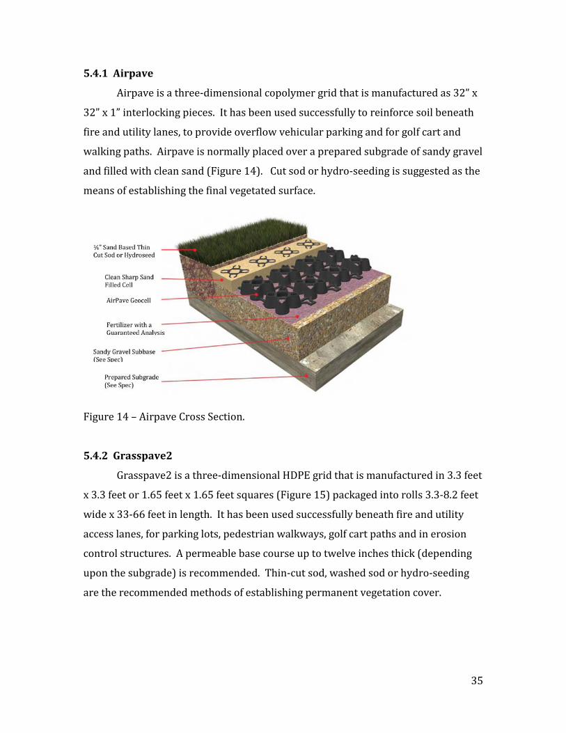
5.4.1 Airpave
Airpave is a three-dimensional copolymer grid that is manufactured as 32” x
32” x 1” interlocking pieces. It has been used successfully to reinforce soil beneath
fire and utility lanes, to provide overflow vehicular parking and for golf cart and
walking paths. Airpave is normally placed over a prepared subgrade of sandy gravel
and filled with clean sand (Figure 14). Cut sod or hydro-seeding is suggested as the
means of establishing the final vegetated surface.
Figure 14 – Airpave Cross Section.
5.4.2 Grasspave2
Grasspave2 is a three-dimensional HDPE grid that is manufactured in 3.3 feet
x 3.3 feet or 1.65 feet x 1.65 feet squares (Figure 15) packaged into rolls 3.3-8.2 feet
wide x 33-66 feet in length. It has been used successfully beneath fire and utility
access lanes, for parking lots, pedestrian walkways, golf cart paths and in erosion
control structures. A permeable base course up to twelve inches thick (depending
upon the subgrade) is recommended. Thin-cut sod, washed sod or hydro-seeding
are the recommended methods of establishing permanent vegetation cover.

36
Figure 15 – Grasspave2 Showing Infill Material.
5.4.3 Geoblock
Geoblock is a recycled polyethylene grid that is marketed as porous
pavement. It is manufactured as 20 inch x 40 inch mats (Figure 16), of one or two
inch thickness. It has been successfully used for grass driveways, walkways, plus
fire and emergency vehicle access lanes. The polyethylene grid should be placed
upon well-drained aggregate or topsoil engineered fill. Material placed as infill
should be conducive to vegetation growth. Sod or hydro-seeding are the
recommended methods of establishing vegetation cover.
Figure 16 – Geoblock Porous Pavement with Sod.

37
5.5 Grids for Aggregate Surfaces
Grids designed for aggregate surfaces are characterized by a greater vertical
dimension than grids used for vegetated surfaces, with thicknesses between two
and eight inches being the most common. Specifications for infill material
(aggregate) differ slightly depending upon the product.
5.5.1 Stabilization Grid
Stabilization grid consists of non-woven geotextile strips thermo-welded into
a cellular matrix (Figure 17). Unfolded area is 25 feet by 4 feet with thickness being
either 2 or 4 inches. Stabilization grid has been used successfully to create parking
lots, driveways, golf cart pathways, and sports fields.
Figure 17 – Stabilization Grid Partially Filled.
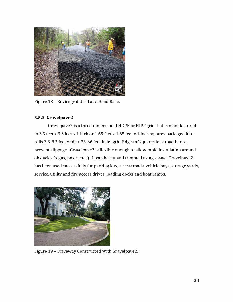
5.5.2 Envirogrid
EnviroGrid is a three dimensional grid composed of sheets of three, four, six
or eight inch high interlocking HDPE cells with mesh thermos-welded across the
bottom. It has been used successfully as a road base (Figure 18), as driveways, for
streets and for beach stabilization projects. Envirogrid is shipped as a 12” x 5” x cell
height bundle which expands to 27.4’ and 8.4‘ x cell height grid when expanded.
Expanded grids are connected to one another using clips and pins.
38
Figure 18 – Envirogrid Used as a Road Base.
5.5.3 Gravelpave2
Gravelpave2 is a three-dimensional HDPE or HIPP grid that is manufactured
in 3.3 feet x 3.3 feet x 1 inch or 1.65 feet x 1.65 feet x 1 inch squares packaged into
rolls 3.3-8.2 feet wide x 33-66 feet in length. Edges of squares lock together to
prevent slippage. Gravelpave2 is flexible enough to allow rapid installation around
obstacles (signs, posts, etc.,). It can be cut and trimmed using a saw. Gravelpave2
has been used successfully for parking lots, access roads, vehicle bays, storage yards,
service, utility and fire access drives, loading docks and boat ramps.
Figure 19 – Driveway Constructed With Gravelpave2.

39
5.5.4 Geopave
Geopave is a recycled polyethylene grid that is manufactured in 20 inch x 40
inch mats, two inches in thickness. It has been successfully used to reinforce soil
beneath trails, fire and emergency vehicle access lanes plus temporary and
permanent parking lots. The grid can be installed on top of an engineered drainage
layer varying from two to six inches in depth depending upon the traffic loading
conditions. Geopave is recommended for use on highway (aggregate) shoulders
and is advertised as a “natural storm water retention system”.
Figure 20 – Constructing Parking with Geopave.
5.6 Selecting Soil Reinforcing Systems
The various types of artificial soil reinforcement systems mentioned earlier
are shown in Table 2 with their websites listed. Further information about each
product is available from the websites.
A soil reinforcement system should ideally have reinforcing material
available in large rolls for repair of extended areas when necessary. Sections of
reinforcing material should be detachable as smaller units for repair of localized
edge drop off. A similar system could be used for repair of both vegetated and
granular shoulders with only the infill material being different between the two
applications. Infill material would consist of soil/seed where a vegetated shoulder
is desired and some type of aggregate where the shoulder is expected to remain
unvegetated.

40
Table 2 – Artificial Soil Reinforcement Systems.
The presence or absence of vegetation along the highway shoulder is the best
indicator of what that shoulder’s surface will ultimately resemble. If vegetation is
growing near a highway’s edge, a system that stabilizes soil while supporting
vegetation growth would be ideal. Two systems considered appropriate which
promote vegetation growth are Grasspave2 and Geoblock (Figure 21).
Figure 21 - Grids for Vegetated Shoulders.
Surface Product Website Meshes Vegetation Terratame2 http://www.invisiblestructures.com/terratame2.html
Vegetation Grass Protecta http://www.typargeosynthetics.com/
Grids Vegetation Airpave http://www.airfieldsystems.com/grass-pave/
Vegetation Grasspave2 http://www.invisiblestructures.com/grasspave2.html
Vegetation Geoblock http://www.prestogeo.com/geoblock_porous_pavement
Aggregate Stabilization Grid http://www.landscapediscount.com/Ground-Grid-DuPont-p/dpgg-5055.htm
Aggregate Envirogrid http://iwtcargoguard.com/products/envirogrid-cellular-confinement-system/
Aggregate Gravelpave2 http://www.invisiblestructures.com/gravelpave2.html
Aggregate Geopave http://www.prestogeo.com/geopave_porous_pavement

41
Grasspave2 and Geoblock can be purchased in large rolls for placement over
extended areas. Rolls of each can be disassembled into smaller pieces. Smaller
pieces can be hand-placed for more localized repair work at specific locations.
Similar systems produced by the same manufacturers for aggregate
shoulders are Gravelpave2 and Geopave (Figure 22). These systems perform better
when installed over an aggregate base course which functions as a drainage layer.
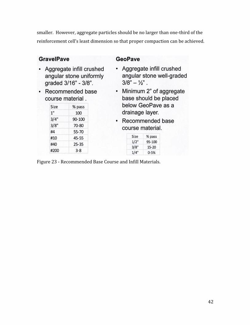
Manufacturer’s suggestions for base course include material ranging in size from
0.1875 – 0.5 inches (Figure 23).
Because the primary function of the base course is to act as a drainage layer,
any material with good hydraulic conductivity should be acceptable. Acceptable
base course materials include Nebraska’s 47B aggregate. Theoretically, any
material with less than ten percent passing the #200 sieve could be used to
construct a base course.
Figure 22 - Grids for Aggregate Shoulders.
Infill material must resist vertical forces imposed by wheel loads, so angular
aggregate will perform better than smooth. The top surface of infill material must
resist movement by air and water, so larger particles will perform better than
42
smaller. However, aggregate particles should be no larger than one-third of the
reinforcement cell’s least dimension so that proper compaction can be achieved.
Figure 23 - Recommended Base Course and Infill Materials.
43
Chapter 6
Recommendations 6.1 Research Focus and Limitations
This study focused on documenting methods and procedures used
successfully by the NDOR districts and by other state DOTs to mitigate pavement
edge drop off. The goal of this research was consolidation of institutional
knowledge, making it available for dissemination to district design and maintenance
personnel across Nebraska. No funding for field trials or for testing of
recommended pavement edge drop off mitigation procedures was included in this
study’s submission.
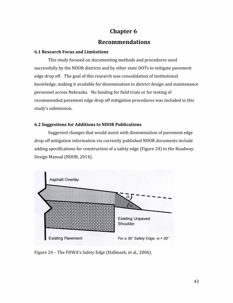
6.2 Suggestions for Additions to NDOR Publications
Suggested changes that would assist with dissemination of pavement edge
drop off mitigation information via currently published NDOR documents include
adding specifications for construction of a safety edge (Figure 24) to the Roadway
Design Manual (NDOR, 2014).
Figure 24 – The FHWA’s Safety Edge (Hallmark, et al., 2006).

44
Initial studies by Humphreys and Parham (1994) recommended a 45o safety
edge sloping downward from the top edge of the overlay toward the top edge of the
existing unpaved shoulder. A 30o safety edge was found to have a higher degree of
safety regardless of the degree of longitudinal elevation change (Ivey, 2008) and
was much easier to construct. Crossing a 30o slope has roughly 60% of the
detrimental effects of crossing a 45o slope of the same vertical height (Ivey, 2008),
so the safety edge ultimately adopted (and promoted) by the FHWA incorporated
the 30o (versus 45o) angle. A safety edge can be added to bituminous overlays with
almost zero impact on productivity while adding less than one percent to material
costs (Wagner, 2004).
The Roadway Design Manual could be modified to include information added
about stabilizing highway shoulder material characterized by a high plasticity index.
This practice is already being required by the NDOR for highway subgrades.
Provisions for subgrade preparation could simply be extended to cover shoulder
material as well. Reducing the plasticity index of materials used for shoulder
construction will limit the range of water contents over which the shoulder is most
subject to rutting.
Specifications for soil that has the ability to support vegetation growth (on
highway shoulders) could be added to the Roadside Vegetation Establishment and
Management (NDOR, 2014) guide. Specifications might include the requirement
that only topsoil can be used as the shoulder’s surface layer where vegetation is the
desired surface cover. Compaction could be limited or prohibited, as compaction
minimizes void space needed for successful root development as vegetation
matures.
6.3 Suggestions for Future Research
District maintenance personnel may wish to experiment with raw edging
and/or strip sealing/edge sealing (mentioned under Texas Initiatives) as methods
to extend the lifespan of asphalt overlays. Cost of these strategies is significantly
less than for fog sealing or chip sealing applied across the entire width of pavement.

45
These procedures are considered to be both effective and economical and are used
extensively by the State of Texas.
During TAC meetings, several research initiatives were suggested that have
the potential to provide valuable data which could improve highway shoulder drop
off mitigation procedures in Nebraska. Some of these include:
• Field testing to determine whether broadcast seeding or drilling
produces thicker and more uniform shoulder vegetation.
• Field testing to determine whether the current practice of placing
cattle manure on unvegetated highway shoulders encourages
satisfactory establishment of local vegetation.
• Field testing of soil reinforcement meshes and grids using agricultural
machinery and/or cattle as loads.
6.4 Conclusions
Current NDOR practices will mitigate many of the problems associated with
pavement edge drop off as they become more commonly employed on Nebraska
highways in future years. The most economical way for the NDOR to mitigate
present and future hazards associated with pavement edge drop off is to issue
resurfacing/reconstruction contracts that require providing a stabilized shoulder
flush with the pavement surface as an integral part of each contract. All resurfacing
contracts for lanes with unpaved shoulders should require that the pavement be
constructed with a 30° safety edge per FHWA guidance.
Effective shoulder maintenance requires many different strategies depending
upon climate, soil composition and type of shoulder material. Most NDOR districts
have multiple variations of climate, soil composition and type of shoulder material
to consider, which necessitates that maintenance personnel apply the most
appropriate strategy for many differing sets of conditions. NDOR district
maintenance personnel seem to have adapted well to this challenge and are either
using or experimenting with strategies that effectively mitigate pavement edge drop
off in a wide variety of situations.

46
References AASHTO (1999). Guide for Development of Bicycle Facilities. American Association of State Highway and Transportation Officials, Washington, D.C. 20001.
AASHTO (2001). A Policy on Geometric Design of Highways and Streets. American Association of State Highway and Transportation Officials, Washington, D.C. 20001.
AASHTO (2002). Roadside Design Guide. American Association of State Highway and Transportation Officials, Washington, D.C. 20001.
AASHTO (2004). Manual on Uniform Traffic Control Devices. American Association of State Highway and Transportation Officials, Washington, D.C. 20001.
AASHTO (2008). Driving Down Lane-Departure Crashes: A National Priority. American Association of State Highway and Transportation Officials, Washington, D.C. 20001.
FHWA (1992). Selecting Roadway Design Treatments to Accommodate Bicycles. Report FHWA-RD-92-073. Federal Highway Administration, Washington, D.C. 20590.
FHWA (2012a). Standard Specifications for Construction of Roads and Bridges on Federal Highway Projects. Federal Highway Administration, Washington, D.C. 20590.
FHWA (2012b). Safety Edge. Downloaded on 3/1/2015 from http://www.fhwa.dot.gov/everydaycounts/technology/safetyedge/intro.cfm.
Glennon, J.C. (1985). Effect of Pavement/Shoulder Drop-Offs on Highway Safety: A Synthesis of Prior Research. Transportation Research Board, Washington, D.C.
Glennon, J. C. (2005). A Primer on Pavement Edge Drop Offs, CrashForensics.com, downloaded from http://www.crashforensics.com/papers.cfm?PaperID=26 on April 6, 2015.
Hallmark, S., Veneziano, D., McDonald, T., Graham J. Bauer, K.M. and Patel, R. (2006). Safety Effects of Pavement Edge Drop offs, AAA Foundation for Traffic Safety, 607 14th Street NW, Washington, D.C. 20005.

47
Humphreys, J.D. and Parham, J.A. (1994). Elimination or Mitigation of Hazards Associated with Pavement Edge Drop offs During Roadway Resurfacing, AAA Foundation for Traffic Safety, Washington, D.C. 20005.
Ivey, D.L., Mak, K.K., Cooner, H.D. and Mareky, M.A. (1988). Safety in Construction Zones Where Pavement Edges and Drop-Offs Exist, Journal of the Transportation Research Record, 1163:43-62.
Ivey, D. L. (2008). Innovations in Asphaltic Pavement Edge Profiles to Improve Safety and Reduce Maintenance Costs, Texas A&M University, College Station, TX 77843-9356.
Jahren, C.T., White, D.J., Phan, T.H., Westercamp, C., and Becker, P. (2011). Stabilization Procedures to Mitigate Edge Rutting for Granular Shoulders –Phase II. IHRB Project TR-591, Center for Transportation Research and Education, Iowa State University, Ames IA 50010-8664.
Lawson, W. and Hossain, M. (2004). Best Practices for Pavement Edge Management, Research Report 0-4396-1, Center for Multidisciplinary Research in Transportation, Texas Tech University, Lubbock, TX 79409.
NDOR Specifications for Highway Construction (2007). The Nebraska Department of Roads, 1500 Highway 2, Lincoln, NE 68509-4759.
NDOR Pavement Design Manual (2013). The Nebraska Department of Roads, 1500 Highway 2, Lincoln, NE 68509-4759.
NDOR Roadway Design Manual (2014). The Nebraska Department of Roads, 1500 Highway 2, Lincoln, NE 68509-4759.
NDOR Roadside Vegetation Establishment and Management (2014). The Nebraska Department of Roads, 1500 Highway 2, Lincoln, NE 68509-4759.
Shoulder Safety and Maintenance (2009). MnROAD downloaded from http://www.mrr.dot.state.mn.us/research/pdf/2009MRRDOC014.pdf on 8/6/2014.
Souleyrette, R., McDonald, T., Hans, Z., Kamyab, A., Welch, T. and Storm B. (2001). Paved Shoulders on Primary Highways in Iowa: Analysis of Shoulder Surfacing Criteria, Cost and Benefits. Center for Transportation Research and Education, Iowa State University, Ames, IA 50010-8664.
TxDOT Maintenance Manual (2001). Maintenance Division, Texas Department of Transportation, Austin, TX 78701.
48
Texas Transportation Institute (1996). Buffalo Grass Less Harmful to Road Shoulder Than Traditional Bermuda Grass, Texas Transportation Researcher, Vol. 32, No. 2, TTI, College Station, TX 77843-3135.
Wagner, C. (2004). Construction of a Safe Pavement Edge: Minimizing the Effects of Shoulder Dropoff, 2005 Transportation Research Board Annual Meeting, downloaded from http://www.transtechsys.com/pdf/trb%20swm.pdf on 8/5/2014.
Washington State DOT (2014). Downloaded on 12/9/2014 from http://www.wsdot.wa.gov/Design/Policy/RumbleStrips.htm.
White, D., Mekkawy, M., Jahren, C., Smith D., and Suleiman, M. (2007). Effective Shoulder Design and Maintenance, IHRB Project TR-531, Center for Transportation Research and Education, Iowa State University, Ames IA 50010-8664.