Mit Owners_Guide_c
79
Projection Television Models VS-50111, VS-60111, WT-42311, WS-48311, WS-55311, WS-65311, WS-55411, WS-65411 and WS-73411 visit our website at www.mitsubishi-tv.com ®
Transcript of Mit Owners_Guide_c
Projection Television Models VS-50111, VS-60111, WT-42311, WS-48311, WS-55311, WS-65311, WS-55411, WS-65411 and WS-73411
visit our website at
www.mitsubishi - tv.com
®
CAUTION: TO REDUCE THE RISK OF ELECTRIC SHOCK, DO NOT REMOVE COVER (OR BACK).NO USER SERVICEABLE PARTS INSIDE.REFER SERVICING TO QUALIFIED SERVICE PERSONNEL.
CAUTIONRISK OF ELECTRIC SHOCKDO NOT OPEN
The lightning flash with arrowhead symbol within an equilateral triangle is intended to alert the user of the presence of uninsulated “dangerous voltage” within the product’s enclosure that may be sufficient magnitude to constitute a risk of electric shock.
The exclamation point within an equilateral triangle is intended to alert the user to the presence of important operating and maintenance (servicing) instructions in the literature accompanying the appliance.
Warning: To avoid permanently imprinting a fixed image onto your TV screen, please do not display the same stationary images on the screen for more than 15% of your total TV viewing in one week. Examples of stationary images are letterbox top/bottom bars from DVD disk or other video sources, side bars when showing standard TV pictures on widescreen TV’s, stock market reports, video game patterns, station logos, web sites or stationary computer images. Such patterns can unevenly age the picture tubes causing permanent damage to the TV. Please see page 51 for a detailed explanation.
Note: This equipment has been tested and found to comply with the limits for a Class B digital device, pursuant to part 15 of the FCC Rules. These limits are designed to provide reasonable protection against harmful interference in a residential installation. This equipment generates, uses and can radiate radio frequency energy and, if not installed and used in accordance with the instructions, may cause harmful interference to radio communications. However, there is no guarantee that interference will not occur in a particular installation. If this equipment does cause harmful interference to radio or television reception, which can be determined by turning the equipment off and on, the user is encouraged to try to correct the interference by one or more of the following measures:
• Reorient or relocate the receiving antenna.• Increase the separation between the equipment and the receiver.• Connect the equipment into an outlet on a circuit different from that to which the receiver is
connected.• Consult the dealer or an experienced radio/TV technician for help.
Changes or modifications not expressly approved by Mitsubishi could void the user’s authority to operate this equipment.
WARNING:TO REDUCE THE RISK OF FIRE OR ELECTRIC SHOCK, DO NOT EXPOSE THIS APPLIANCE TO RAIN OR MOISTURE.
CAUTION:TO PREVENT ELECTRIC SHOCK, MATCH WIDE BLADE OF PLUG TO WIDE SLOT, FULLY INSERT.NOTE TO CATV SYSTEM INSTALLER:THIS REMINDER IS PROVIDED TO CALL THE CATV SYSTEM INSTALLER’S ATTENTION TO ARTICLE 820-40 OF THE NEC THAT PROVIDES GUIDELINES FOR THE PROPER GROUNDING AND, IN PARTICULAR, SPECIFIES THAT THE CABLE GROUND SHALL BE CONNECTED TO THE GROUNDING SYSTEM OF THE BUILDING, AS CLOSE TO THE POINT OF CABLE ENTRY AS PRACTICAL.
33
OPERATION
SETUP
INSTALLATION
INTRO
Table o
f Co
nten
ts
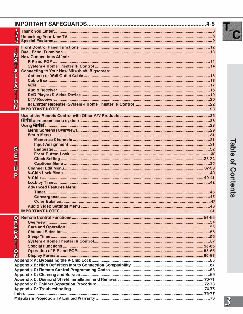
IMPORTANT SAFEGUARDS.............................................................................4-5 Thank You Letter...............................................................................................................................................8 Unpacking Your New TV...................................................................................................................................9 Special Features ...............................................................................................................................................9
Front Control Panel Functions ......................................................................................................................12 Back Panel Functions.....................................................................................................................................13 How Connections Affect: PIP and POP .............................................................................................................................................. 14 System 4 Home Theater IR Control ........................................................................................................ 14 Connecting to Your New Mitsubishi Bigscreen: Antenna or Wall Outlet Cable ..................................................................................................................16 Cable Box...................................................................................................................................................16 VCR ......................................................................................................................................................... 17 Audio Receiver..........................................................................................................................................18 DVD Player /S-Video Device ....................................................................................................................19 DTV Receiver.............................................................................................................................................20 IR Emitter Repeater (System 4 Home Theater IR Control) ...................................................................22 IMPORTANT NOTES .......................................................................................................................................23
Use of the Remote Control with Other A/V Products .................................................................................26 on-screen menu system ......................................................................................................................28 Using .....................................................................................................................................................28 Menu Screens (Overview)........................................................................................................................29 Setup Menu................................................................................................................................................31 Memorize Channels ............................................................................................................................31 Input Assignment................................................................................................................................31 Language .............................................................................................................................................32 Front Button Lock..........................................................................................................................32 Clock Setting ................................................................................................................................ .33-34 Captions Menu ....................................................................................................................................35 Channel Edit Menu...............................................................................................................................37-39 V-Chip Lock Menu.....................................................................................................................................40 V-Chip .................................................................................................................................................. 40-41 Lock by Time .............................................................................................................................................42 Advanced Features Menu Timer.....................................................................................................................................................43 Convergence........................................................................................................................................45 Color Balance.................................................................................................................................47 Audio Video Settings Menu .....................................................................................................................48 IMPORTANT NOTES .......................................................................................................................................51
Remote Control Functions....................................................................................................................... 54-65 Overview ....................................................................................................................................................54 Care and Operation ..................................................................................................................................55 Channel Selection.....................................................................................................................................56 Sleep Timer................................................................................................................................................56 System 4 Home Theater IR Control.........................................................................................................57 Special Functions ............................................................................................................................... 58-65 Operation of PIP and POP.................................................................................................................. 58-65 Display Formats .................................................................................................................................. 60-65Appendix A: Bypassing the V-Chip Lock ...........................................................................................................66Appendix B: High Definition Inputs Connection Compatibility .......................................................................67Appendix C: Remote Control Programming Codes ..........................................................................................68Appendix D: Cleaning and Service .....................................................................................................................69Appendix E: Diamond Shield Installation and Removal ............................................................................. 70-71Appendix F: Cabinet Separation Procedure .................................................................................................72-73Appendix G: Troubleshooting ........................................................................................................................74-75Index ................................................................................................................................................................. 76-77Mitsubishi Projection TV Limited Warranty .......................................................................................................78
44
Imp
ort
ant
Saf
egu
ard
s
IMPORTANT SAFEGUARDSPlease read the following safeguards for your TV and retain for future reference.Always follow all warnings and instructions marked on the television.
1. Read, Retain and Follow All InstructionsRead all safety and operating instructions before operating the TV. Retain the safety and operating instructions for future reference. Follow all operating and use instructions.
2. Heed WarningsAdhere to all warnings on the appliance and in the operating instructions.
3. CleaningUnplug the TV from the wall outlet before cleaning. Do not use liquid, abrasive, or aerosol cleaners. Cleaners can permanently damage the cabinet and screen. Use a lightly dampened cloth for cleaning.
4. Attachments and EquipmentNever add any attachments and/or equipment without approval of the manufacturer as such additions may result in the risk of fire, electric shock or other personal injury.
5. Water and MoistureDo not use the TV where contact with or immersion in water is possible. Do not use near bath tubs, wash bowls, kitchen sinks, laundry tubs, swimming pools, etc.
6. AccessoriesDo not place the TV on an unstable cart, stand, tripod, or table. The TV may fall, causing serious injury to a child or adult and serious damage to the TV. Use only with a cart, stand, tripod, bracket, or table recommended by the manufacturer, or sold with the TV. Any mounting of the TV should follow the manufacturer’s instructions, and should use mounting accessories recommended by the manufacturer.
An appliance and cart combination should be moved with care. Quick stops, excessive force, and uneven surfaces may cause the appliance and cart combination to overturn.
7. VentilationSlots and openings in the cabinet are provided for ventilation and to ensure reliable operation of the TV and to protect it from overheating. Do not block these openings or allow them to be obstructed by placing the TV on a bed, sofa, rug, or other similar surface. Nor should it be placed over a radiator or heat register. If the TV is to be placed in a rack or bookcase, ensure that there is adequate ventilation and that the manufacturer’s instructions have been adhered to.
8. Power SourceThis TV should be operated only from the type of power source indicated on the marking label. If you are not sure of the type of power supplied to your home, consult your appliance dealer or local power company.
9. Grounding or PolarizationThis TV is equipped with a polarized alternating current line plug having one blade wider than the other. This plug will fit into the power outlet only one way. If you are unable to insert the plug fully into the outlet, try reversing the plug. If the plug should still fail to fit, contact your electrician to replace your obsolete outlet. Do not defeat the safety purpose of the polarized plug.
10. Power-Cord ProtectionPower-supply cords should be routed so that they are not likely to be walked on or pinched by items placed upon or against them, paying particular attention to cords at plugs, convenience receptacles, and the point where they exit from the TV.
11. LightningFor added protection for this TV during a lightning storm, or when it is left unattended and unused for long periods of time, unplug it from the wall outlet and disconnect the antenna or cable system. This will prevent damage to the TV due to lightning and power-line surges.
55
Imp
ortan
t Safeg
uard
s
IMPORTANT SAFEGUARDS Continued
12. Power LinesAn outside antenna system should not be located in the vicinity of overhead power lines or other electric light or power circuits, or where it can fall into such power lines or circuits. When installing an outside antenna system, extreme care should be taken to keep from touching such power lines or circuits as contact with them might be fatal.
13. OverloadingDo not overload wall outlets and extension cords as this can result in a risk of fire or electric shock.
14. Object and Liquid EntryNever push objects of any kind into this TV through openings as they may touch dangerous voltage points or short-out parts that could result in fire or electric shock. Never spill liquid of any kind on or into the TV.
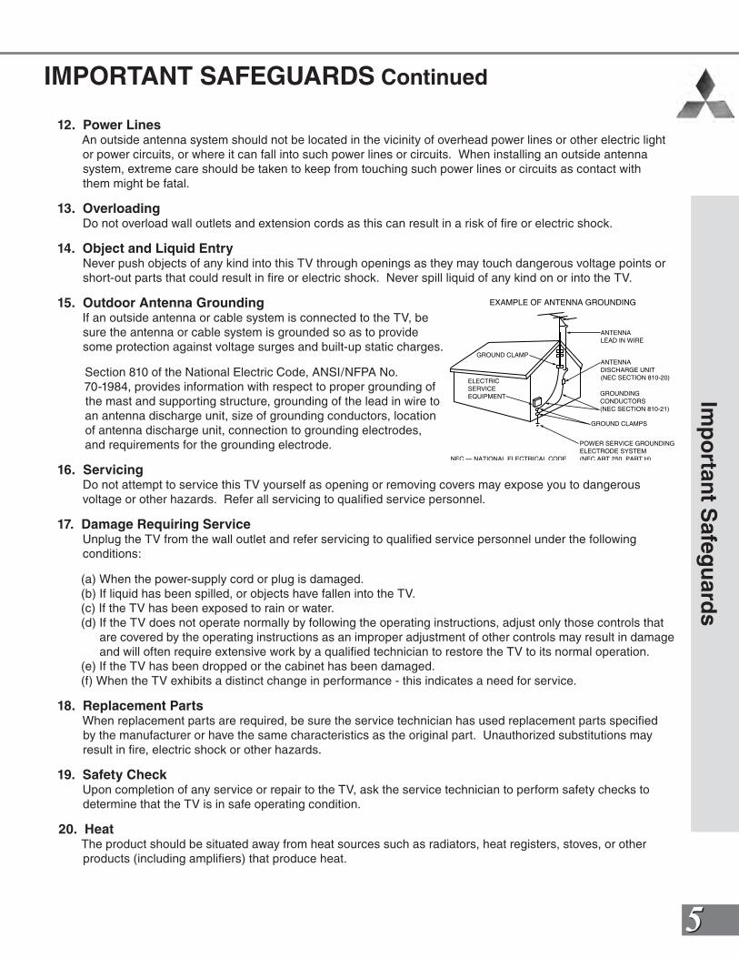
15. Outdoor Antenna GroundingIf an outside antenna or cable system is connected to the TV, be sure the antenna or cable system is grounded so as to provide some protection against voltage surges and built-up static charges.
Section 810 of the National Electric Code, ANSI/NFPA No. 70-1984, provides information with respect to proper grounding of the mast and supporting structure, grounding of the lead in wire to an antenna discharge unit, size of grounding conductors, location of antenna discharge unit, connection to grounding electrodes, and requirements for the grounding electrode.
16. ServicingDo not attempt to service this TV yourself as opening or removing covers may expose you to dangerous voltage or other hazards. Refer all servicing to qualified service personnel.
17. Damage Requiring ServiceUnplug the TV from the wall outlet and refer servicing to qualified service personnel under the following conditions:
(a) When the power-supply cord or plug is damaged.(b) If liquid has been spilled, or objects have fallen into the TV.(c) If the TV has been exposed to rain or water.(d) If the TV does not operate normally by following the operating instructions, adjust only those controls that
are covered by the operating instructions as an improper adjustment of other controls may result in damage and will often require extensive work by a qualified technician to restore the TV to its normal operation.
(e) If the TV has been dropped or the cabinet has been damaged.(f) When the TV exhibits a distinct change in performance - this indicates a need for service.
18. Replacement PartsWhen replacement parts are required, be sure the service technician has used replacement parts specified by the manufacturer or have the same characteristics as the original part. Unauthorized substitutions may result in fire, electric shock or other hazards.
19. Safety CheckUpon completion of any service or repair to the TV, ask the service technician to perform safety checks to determine that the TV is in safe operating condition.
20. HeatThe product should be situated away from heat sources such as radiators, heat registers, stoves, or other products (including amplifiers) that produce heat.
ANTENNALEAD IN WIRE
ANTENNADISCHARGE UNIT(NEC SECTION 810-20)
GROUNDINGCONDUCTORS(NEC SECTION 810-21)
GROUND CLAMPS
POWER SERVICE GROUNDINGELECTRODE SYSTEM(NEC ART 250 PART H)
GROUND CLAMP
ELECTRICSERVICEEQUIPMENT
NEC — NATIONAL ELECTRICAL CODE
EXAMPLE OF ANTENNA GROUNDING

CONSUMER RELATIONS
If you have questions regarding your television Call (800) 332-2119, or email us at
MDEAserv [email protected]
REMOTE CONTROL AND OWNER’S GUIDE
Call (800) 553-7278 to order a replacement Remote Control or Owner’s Guide.
Or visit our website at
www.Mitsubishi -TV.com
77
IntroductionThank You Letter..............................8
Unpacking Your New TV .................9
Special Features ..............................9
88
Th
ank
You
Let
ter
We at Mitsubishi Would Like to Thank You
To the Mitsubishi Consumer:
Welcome to the wonderful and exciting world of digital television! We are honored that you chose Mitsubishi as your premier home entertainment partner. The development team at Mitsubishi understands that our customers demand and expect the very best. Mitsubishi is founded on the core beliefs and philosophies that drive us to deliver products that are both cutting-edge and upgradeable.
While some televisions are destined for near-future obsolescence, Mitsubishi’s HD-upgradeable televisions are engineered with “future-ability.” Your television will continue to provide unparalleled home entertainment for years!
Whether this is your first Mitsubishi consumer electronics product or an addition to your growing Mitsubishi family, we hope that this television will bring you and your family many hours of enjoyment.
THE PROMISE
We will engineer and manufacture the upgrades necessary so the HD-Upgradeable television you purchased today can be made compatible with near-future advances in digital television and digital interconnectivity. Specifically, we promise that you will be able to have your television upgraded, at a reasonable cost, to include an off-air HDTV tuner, a cable TV tuner (for unscrambled programming), an IEEE 1394 (FireWire®) connection, HAVi system control, and 5C copy protection.
99
Un
packin
g Yo
ur N
ew T
V / S
pecial F
eatures
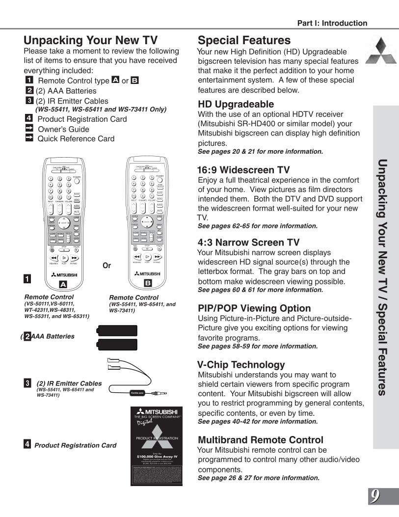
Unpacking Your New TVPlease take a moment to review the following list of items to ensure that you have received everything included:1 Remote Control type A or B 2 (2) AAA Batteries3 (2) IR Emitter Cables
(WS-55411, WS-65411 and WS-73411 Only)
4 Product Registration Card Owner’s Guide Quick Reference Card
POWER
INFO
PAUSEREC
FF/FWDREW/REV PLAY
STOP
3
6
9
QV
VOLUME
GUIDE
EXCH
ENTER
CANCEL MENU
V-CHIP
FORMAT
PIP CH
1
7
SQV
4
INPUT
SLEEP
VIDEO
AUDIO
MUTE
2
5
8
0
CHANNEL
ADJUST
PIP INPUT
PIP/POP
HOME
TV AUDIOCABLE/DBS DVD
VCR
Remote Control(VS-50111,VS-60111,WT-42311,WS-48311,WS-55311, and WS-65311)
(2) AAA Batteries
Special FeaturesYour new High Definition (HD) Upgradeable bigscreen television has many special features that make it the perfect addition to your home entertainment system. A few of these special features are described below.
HD UpgradeableWith the use of an optional HDTV receiver (Mitsubishi SR-HD400 or similar model) your Mitsubishi bigscreen can display high definition pictures.See pages 20 & 21 for more information.
16:9 Widescreen TVEnjoy a full theatrical experience in the comfort of your home. View pictures as film directors intended them. Both the DTV and DVD support the widescreen format well-suited for your new TV. See pages 62-65 for more information.
4:3 Narrow Screen TVYour Mitsubishi narrow screen displays widescreen HD signal source(s) through the letterbox format. The gray bars on top and bottom make widescreen viewing possible.See pages 60 & 61 for more information.
PIP/POP Viewing OptionUsing Picture-in-Picture and Picture-outside- Picture give you exciting options for viewing favorite programs.See pages 58-59 for more information.
V-Chip TechnologyMitsubishi understands you may want to shield certain viewers from specific program content. Your Mitsubishi bigscreen will allow you to restrict programming by general contents, specific contents, or even by time.See pages 40-42 for more information.
Multibrand Remote ControlYour Mitsubishi remote control can be programmed to control many other audio/video components.See page 26 & 27 for more information.
Ferrite core
Remote Control(WS-55411, WS-65411, and WS-73411)
2
1
3
4
(2) IR Emitter Cables(WS-55411, WS-65411 and WS-73411)
Product Registration Card
A B
Or
Part l: Introduction

1111
InstallationFront Control Panel .......................12Back Panel ....................................13
How Connections Affect: PIP and POP...............................14 System 4 Home Theater IR Control ...................................14
Connecting Your New Mitsubishi Bigscreen: Antenna or Wall Outlet Cable ...16 Cable Box ...................................16 VCR .............................................17 Audio Receiver...........................18 DVD Player..................................19 DTV Receiver .............................20 Connecting the System 4 Home Theater IR Control ...................22
IMPORTANT NOTES ......................23
1212
VOL CH
ENTER
MENU A/V RESET INPUT
ADJUST ADJUST CANCEL MENU
INPUT-3
S-VIDEO VIDEO L-AUDIO-R
ENTER
TIMER
POWER
Fro
nt
Co
ntr
ol P
anel
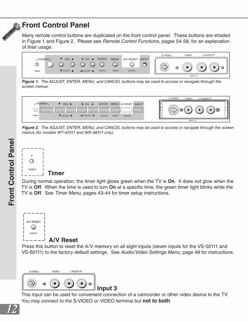
Front Control PanelMany remote control buttons are duplicated on the front control panel. These buttons are shaded in Figure 1 and Figure 2. Please see Remote Control Functions, pages 54-58, for an explanation of their usage.
Figure 1. The ADJUST, ENTER, MENU, and CANCEL buttons may be used to access or navigate through the screen menus.
TIMER
TimerDuring normal operation, the timer light glows green when the TV is On. It does not glow when the TV is Off. When the time is used to turn On at a specific time, the green timer light blinks while the TV is Off. See Timer Menu, pages 43-44 for timer setup instructions.
A/V RESET
CANCEL
A/V ResetPress this button to reset the A/V memory on all eight inputs (seven inputs for the VS-50111 and VS-60111) to the factory default settings. See Audio/Video Settings Menu, page 48 for instructions.
S-VIDEO VIDEO L-AUDIO-R
Input 3This input can be used for convenient connection of a camcorder or other video device to the TV. You may connect to the S-VIDEO or VIDEO terminal but not to both.
VOL CH
ENTER
MENU A/V RESET INPUT
ADJUST ADJUST CANCEL MENU
ENTER
TIMER
POWER
INPUT-3
S-VIDEO VIDEO L-AUDIO-R
Figure 2. The ADJUST, ENTER, MENU, and CANCEL buttons may be used to access or navigate through the screen menus (for models WT-42311 and WS-48311 only).
1313
21
4
65
3
COMPONENT 480 i / 480P/ 1080i
AUDIO -RIGHT
L E FT /( MONO)
AUDIO -
DT V (YPbPr/ GBRHV )
MONITOR I N P U TOUT 21
AN T - A AN T- BLOO POUT
480 i / 480P /1080 i
AUDIO-
RIGHT
AUDIO-
LEFT /
(MONO)
V I D EO
S-VIDEO
2
IR EMITTER REPEATER
Y
P r
P b
V
H
Y
G
Pb
B
P r
R
TV Back Panel
Back P
anel
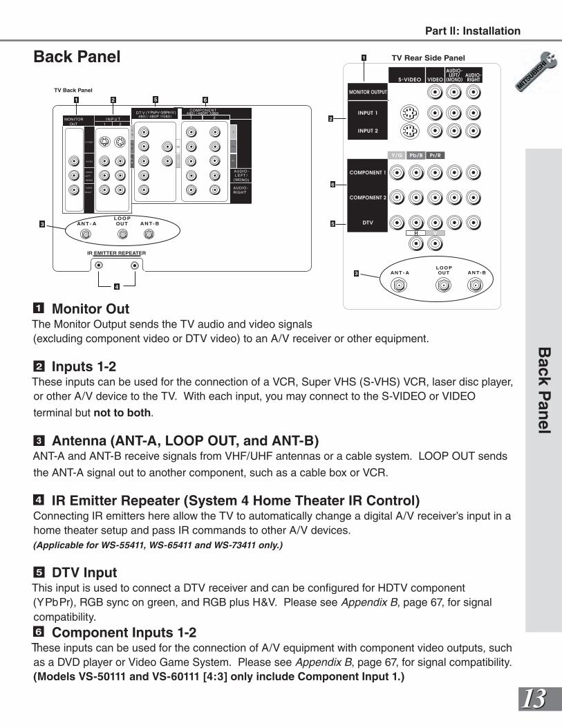
1 Monitor OutThe Monitor Output sends the TV audio and video signals (excluding component video or DTV video) to an A/V receiver or other equipment.
2 Inputs 1-2These inputs can be used for the connection of a VCR, Super VHS (S-VHS) VCR, laser disc player, or other A/V device to the TV. With each input, you may connect to the S-VIDEO or VIDEO
terminal but not to both.
3 Antenna (ANT-A, LOOP OUT, and ANT-B)ANT-A and ANT-B receive signals from VHF/UHF antennas or a cable system. LOOP OUT sends
the ANT-A signal out to another component, such as a cable box or VCR.
4 IR Emitter Repeater (System 4 Home Theater IR Control)Connecting IR emitters here allow the TV to automatically change a digital A/V receiver’s input in a home theater setup and pass IR commands to other A/V devices. (Applicable for WS-55411, WS-65411 and WS-73411 only.)
5 DTV InputThis input is used to connect a DTV receiver and can be configured for HDTV component (YPbPr), RGB sync on green, and RGB plus H&V. Please see Appendix B, page 67, for signal compatibility. 6 Component Inputs 1-2
These inputs can be used for the connection of A/V equipment with component video outputs, such as a DVD player or Video Game System. Please see Appendix B, page 67, for signal compatibility. (Models VS-50111 and VS-60111 [4:3] only include Component Input 1.)
1
2
3 AN T - A AN T- BLOO POUT
6
5
TV Rear Side PanelBack Panel
Part ll: Installation
1414
PIP / POPMain
Ant-A
Ant-B
DTV480i, 480p, 1080i
Input-1 Input-2Input-3
Component-1(Component-2)480i, 480p,1080i
Ant-A Ant-BDTV480i, 480p,1080i
Input-1 Input-2Input-3
Component-1(Component-2)480i, 480p,1080i
OK*
OK
OK
OK
OK OK OK OK
OK
OK
OK
OKOK
OK
OK
OK
OK
OKOK
OK
No PIP/POP
OK*
OK**
OK**
OK**
Ho
w C
on
nec
tio
ns
Aff
ect
the
PIP
an
d P
OP
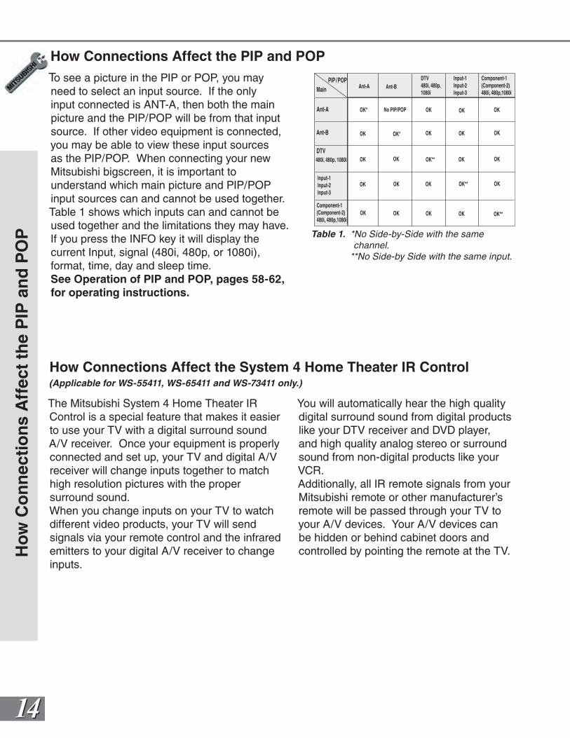
How Connections Affect the PIP and POPTo see a picture in the PIP or POP, you may need to select an input source. If the only input connected is ANT-A, then both the main picture and the PIP/POP will be from that input source. If other video equipment is connected, you may be able to view these input sources as the PIP/POP. When connecting your new Mitsubishi bigscreen, it is important to understand which main picture and PIP/POP input sources can and cannot be used together. Table 1 shows which inputs can and cannot be used together and the limitations they may have. If you press the INFO key it will display the current Input, signal (480i, 480p, or 1080i), format, time, day and sleep time.See Operation of PIP and POP, pages 58-62, for operating instructions.
Table 1. *No Side-by-Side with the same channel. **No Side-by Side with the same input.
How Connections Affect the System 4 Home Theater IR Control(Applicable for WS-55411, WS-65411 and WS-73411 only.)
The Mitsubishi System 4 Home Theater IR Control is a special feature that makes it easier to use your TV with a digital surround sound A/V receiver. Once your equipment is properly connected and set up, your TV and digital A/V receiver will change inputs together to match high resolution pictures with the proper surround sound.When you change inputs on your TV to watch different video products, your TV will send signals via your remote control and the infrared emitters to your digital A/V receiver to change inputs.
You will automatically hear the high quality digital surround sound from digital products like your DTV receiver and DVD player, and high quality analog stereo or surround sound from non-digital products like your VCR.Additionally, all IR remote signals from your Mitsubishi remote or other manufacturer’s remote will be passed through your TV to your A/V devices. Your A/V devices can be hidden or behind cabinet doors and controlled by pointing the remote at the TV.
1515
Ho
w C
on
nectio
ns A
ffect the S
ystem 4 H
om
e Th
eater IR C
on
trol
Special Setups: A/V Equipment
VCR: Connect the cables to the TV as directed on page 17, with one exception. Connect the audio output connection to the appropriate input on the back of the A/V receiver (as shown in Table 1).
DVD: Connect the cables as directed on page 19 (using the COMPONENT-1 input), with one exception. Connect the digital audio output connection on the DVD player to the appropriate digital input on the back of the digital A/V receiver (as shown in Table 1).
DTV: Connect the cables as directed on pages 20-21, with one exception. Connect the digital audio output connection on the DTV receiver to the appropriate digital input on the back of the digital A/V receiver (as shown in Table 1).
A/V Receiver: Connect as directed on page 18, with two additions. Use an S-Video cable in step 1 if you have an S-Video VCR. The TV outputs should be connected to the A/V receivers input marked TV.
•Auto Standby: ON (See your A/V receiver’s Owner’s Guide for this procedure). For all TV use, the sound will come from the A/V receiver. Not available with all A/V receivers.
•Digital Input Assignment for DVD: Assign the digital input you used for your DVD player to the A/V receiver’s DVD input selector. This procedure is explained in your A/V receiver’s Owner’s Guide.
•Digital Assignment for DTV: Assign the digital input you used for DTV to the A/V receiver’s DTV input selector. This procedure is explained in your A/V receiver’s Owner’s Guide.
Infrared Emitter: Connect as shown on page 22.
Special Setups: TVTo correctly setup System 4 use the following settings
•TV Speakers: OFF
•Audio Output: Fixed See Audio Video Menu, page 31.
•TV Inputs Appropriately Named See Input Assignment Menu, page 31.
Remote Control, pages 26-27.•Set the slide switch to the TV position and follow the programming instructions using the A/V receiver code appropriate for your A/V receiver, page 27 (Figure 5).
(For System 4 Home Theater IR Control)
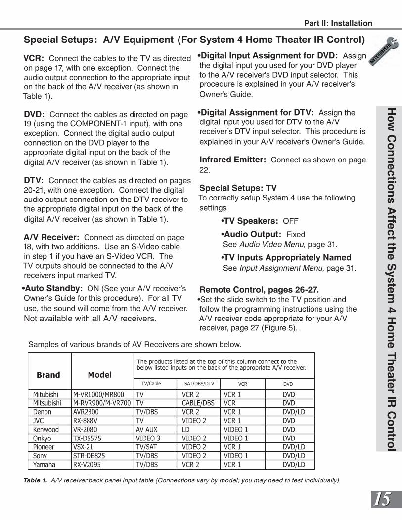
Mitubishi M-VR1000/MR800 TV VCR 2 VCR 1 DVD
Mitsubishi M-RVR900/M-VR700 TV CABLE/DBS VCR DVD
Denon AVR2800 TV/DBS VCR 2 VCR 1 DVD/LD
JVC RX-888V TV VIDEO 2 VCR 1 DVD
Kenwood VR-2080 AV AUX LD VIDEO 1 DVD
Onkyo TX-DS575 VIDEO 3 VIDEO 2 VIDEO 1 DVD
Pioneer VSX-21 TV/SAT VIDEO 2 VCR 1 DVD/LD
Sony STR-DE825 TV/DBS VIDEO 2 VIDEO 1 DVD/LD
Yamaha RX-V2095 TV/DBS VCR 2 VCR 1 DVD/LD
Brand Model
The products listed at the top of this column connect to thebelow listed inputs on the back of the appropriate A/V receiver.
TV/Cable SAT/DBS/DTV VCR DVD
Table 1. A/V receiver back panel input table (Connections vary by model; you may need to test individually)
Samples of various brands of AV Receivers are shown below.
Part ll: Installation
1616
Additional connection cables are not provided with the TV. They should be available at most electronic stores.
Co
nn
ecti
ng
an
An
ten
na,
Wal
l Ou
tlet
Cab
le, o
r C
able
Box
Connecting an Antenna, Wall Outlet Cable, or Cable Box
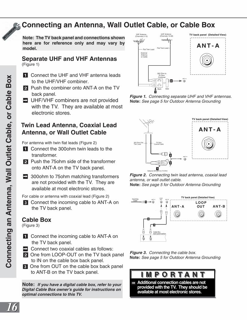
Separate UHF and VHF Antennas(Figure 1)
1 Connect the UHF and VHF antenna leads to the UHF/VHF combiner.
2 Push the combiner onto ANT-A on the TV back panel.
UHF/VHF combiners are not provided with the TV. They are available at most electronic stores.
Twin Lead Antenna, Coaxial Lead Antenna, or Wall Outlet Cable
For antenna with twin flat leads (Figure 2)
1 Connect the 300ohm twin leads to the transformer.
2 Push the 75ohm side of the transformer onto ANT-A on the TV back panel.
300ohm to 75ohm matching transformers are not provided with the TV. They are available at most electronic stores.
For cable or antenna with coaxial lead (Figure 2)
3 Connect the incoming cable to ANT-A on the TV back panel.
Cable Box(Figure 3)
1 Connect the incoming cable to ANT-A on the TV back panel.
Connect two coaxial cables as follows:2 One from LOOP-OUT on the TV back panel
to IN on the cable box back panel.3 One from OUT on the cable box back panel
to ANT-B on the TV back panel.
COMPONENT 480 i / 480P/ 1080i
AUDIO -RIGHT
L E FT /( MONO)
AUDIO -
DT V (YPbPr/ GBRHV )
MONITOR I N P U TOUT 21
AN T - A AN T- BLOO POUT
480 i / 480P /1080 i
AUDIO-
RIGHT
AUDIO-
LEFT /
(MONO)
V I D EO
S-VIDEO
2
IR EMITTER REPEATER
Y
P r
P b
V
H
Y
G
Pb
B
P r
R
ExternalAntennaor Cable
Back Side
Flat Twin Lead
UHF Antenna (Channels 14-69)
VHF Antenna (Channels 2-13)
300 Ohm to75 Ohm Combiner
Flat Twin Lead TV back panel
UHF
VHF
AN T - A
TV back panel (Detailed View)
2
1
Figure 1. Connecting separate UHF and VHF antennas.Note: See page 5 for Outdoor Antenna Grounding
COMPONENT 480 i / 480P/ 1080i
AUDIO -RIGHT
L E FT /( MONO)
AUDIO -
DT V (YPbPr/ GBRHV )
MONITOR I N P U TOUT 21
AN T - A AN T- BLOO POUT
480 i / 480P /1080 i
AUDIO-
RIGHT
AUDIO-
LEFT /
(MONO)
V I D EO
S-VIDEO
2
IR EMITTER REPEATER
Y
P r
P b
V
H
Y
G
Pb
B
P r
R
300 Ohm FlatTwin Lead
Optional 300 Ohm to 75 OhmMatching Transformer
75 OhmCoaxial Cable
1
2
3
TV back panel (Detailed View)
AN T - A
Figure 2. Connecting twin lead antenna, coaxial lead antenna, or wall outlet cable.Note: See page 5 for Outdoor Antenna Grounding
Figure 3. Connecting the cable box.Note: See page 5 for Outdoor Antenna Grounding
COMPONENT 480 i / 480P/ 1080i
AUDIO -RIGHT
L E FT /( MONO)
AUDIO -
DT V (YPbPr/ GBRHV )
MONITOR I N P U TOUT 21
AN T - A AN T- BLOO POUT
480 i / 480P /1080 i
AUDIO-
RIGHT
AUDIO-
LEFT /
(MONO)
V I D EO
S-VIDEO
2
IR EMITTER REPEATER
Y
P r
P b
V
H
Y
G
Pb
B
P r
R
OUT
Cable Box back panel section
IN
IncomingCable
1
2
3
AN T - A AN T- BLOO POUT
TV back panel (Detailed View)
Note: The TV back panel and connections shown here are for reference only and may vary by model.
Note: If you have a digital cable box, refer to yourDigital Cable Box owner’s guide for instructions onoptimal connections to this TV.
1717
Additional connection cables are not provided with the TV. They should be available at most electronic stores.
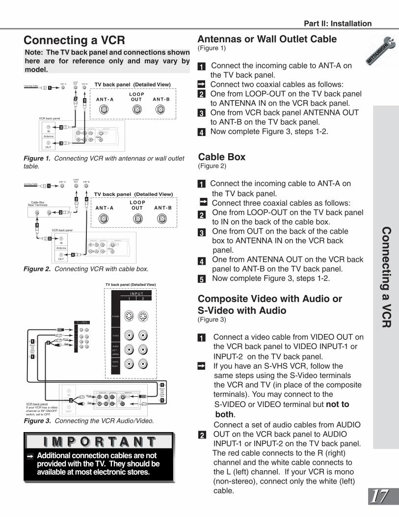
Connecting a VCR Antennas or Wall Outlet Cable(Figure 1)
Connect the incoming cable to ANT-A on the TV back panel. Connect two coaxial cables as follows: One from LOOP-OUT on the TV back panel to ANTENNA IN on the VCR back panel. One from VCR back panel ANTENNA OUT to ANT-B on the TV back panel. Now complete Figure 3, steps 1-2.
Co
nn
ecting
a VC
R
Cable Box(Figure 2)
Connect the incoming cable to ANT-A on the TV back panel. Connect three coaxial cables as follows: One from LOOP-OUT on the TV back panel to IN on the back of the cable box. One from OUT on the back of the cable box to ANTENNA IN on the VCR back
panel. One from ANTENNA OUT on the VCR back panel to ANT-B on the TV back panel. Now complete Figure 3, steps 1-2.
Composite Video with Audio or S-Video with Audio(Figure 3)
Connect a video cable from VIDEO OUT on the VCR back panel to VIDEO INPUT-1 or INPUT-2 on the TV back panel.
If you have an S-VHS VCR, follow the same steps using the S-Video terminals the VCR and TV (in place of the composite terminals). You may connect to the
S-VIDEO or VIDEO terminal but not to both.
Connect a set of audio cables from AUDIO OUT on the VCR back panel to AUDIO INPUT-1 or INPUT-2 on the TV back panel. The red cable connects to the R (right) channel and the white cable connects to the L (left) channel. If your VCR is mono (non-stereo), connect only the white (left) cable.
COMPONENT 480 i / 480P/ 1080i
AUDIO -RIGHT
L E FT /( MONO)
AUDIO -
DT V (YPbPr/ GBRHV )
MONITOR I N P U TOUT 21
AN T - A AN T- BLOO POUT
480 i / 480P /1080 i
AUDIO-
RIGHT
AUDIO-
LEFT /
(MONO)
V I D EO
S-VIDEO
2
IR EMITTER REPEATER
Y
P r
P b
V
H
Y
G
Pb
B
P r
R
AUDIO OUT AUDIO IN VIDEO OUT
(Y/C)
MONITOR
1
L
R
L
R
1 2
IN
OUT
Antenna
VCR back panel
Incoming Cable
Cable BoxRear Terminals
INOUT
1
2 4
2
3
3
4
AN T - A AN T- BLOO POUT
TV back panel (Detailed View)
COMPONENT 480 i / 480P/ 1080i
AUDIO -RIGHT
L E FT /( MONO)
AUDIO -
DT V (YPbPr/ GBRHV )
MONITOR I N P U TOUT 21
AN T - A AN T- BLOO POUT
480 i / 480P /1080 i
AUDIO-
RIGHT
AUDIO-
LEFT /
(MONO)
V I D EO
S-VIDEO
2
IR EMITTER REPEATER
Y
P r
P b
V
H
Y
G
Pb
B
P r
R
AUDIO OUT AUDIO IN VIDEO OUT
(Y/C)
MONITOR
1
L
R
L
R
1 2
Incoming Cable
IN
OUT
Antenna
VCR back panel
1
AN T - A AN T- BLOO POUT
TV back panel (Detailed View)
2
3
2 32
3
4
1
1
2
3
4
5
1
2
Figure 3. Connecting the VCR Audio/Video.
Note: The TV back panel and connections shown here are for reference only and may vary by model.
Figure 1. Connecting VCR with antennas or wall outlet table.
Figure 2. Connecting VCR with cable box.
COMPONENT 480 i / 480P/ 1080i
AUDIO -RIGHT
L E FT /( MONO)
AUDIO -
DT V (YPbPr/ GBRHV )
MONITOR I N P U TOUT 21
AN T - A AN T- BLOO POUT
480 i / 480P /1080 i
AUDIO-
RIGHT
AUDIO-
LEFT /
(MONO)
V I D EO
S-VIDEO
2
IR EMITTER REPEATER
Y
P r
P b
V
H
Y
G
Pb
B
P r
R
I N P U T21
AUDIO-
RIGHT
AUDIO-
LEFT /
(MONO)
V I D EO
S-VIDEO
IN
OUT
Antenna
AUDIO OUT AUDIO IN VIDEO OUT
(Y/C)
MONITOR
1
L
R
L
R
1 2
VCR back panelIf your VCR has a videochannel or RF ON/OFFswitch, set to OFF.
Attachonlyone
cabletype
1
1
Attachonlyone
cabletype
1
1
2
2White
Red
White
Red
TV back panel (Detailed View)
Part ll: Installation
1818
COMPONENT 480 i / 480P/ 1080i
AUDIO -RIGHT
L E FT /( MONO)
AUDIO -
DT V (YPbPr/ GBRHV )
MONITOR I N P U TOUT 21
AN T - A AN T- BLOO POUT
480 i / 480P /1080 i
AUDIO-
RIGHT
AUDIO-
LEFT /
(MONO)
V I D EO
S-VIDEO
2
IR EMITTER REPEATER
Y
P r
P b
V
H
Y
G
Pb
B
P r
R
Yellow
S-Video
A
b
1
1
2
3
White
White
Red
Red
Yellow
MONITOR I N P U TOUT 21
AUDIO-
RIGHT
AUDIO-
LEFT /
(MONO)
V I D EO
S-VIDEO
TV back panel(Detailed View)
AV Receiver (M-VR900)Back panel section
COMPONENT 480 i / 480P/ 1080i
AUDIO -RIGHT
L E FT /( MONO)
AUDIO -
DT V (YPbPr/ GBRHV )
MONITOR I N P U TOUT 21
AN T - A AN T- BLOO POUT
480 i / 480P /1080 i
AUDIO-
RIGHT
AUDIO-
LEFT /
(MONO)
V I D EO
S-VIDEO
2
IR EMITTER REPEATER
Y
P r
P b
V
H
Y
G
Pb
B
P r
R
MONITOROUT
AUDIO-
RIGHT
AUDIO-
LEFT /
(MONO)
V I D EO
S-VIDEO
TV back panel (Detailed View)
Red
Red
Audio system back panel section
OUTOUT
OUT
ININININ SUBWOOFER
(MONO)
CD AUX TAPE 1 TAPE 2
L
R
White
White
1
Please see your A/V receiver Owner’s Guide for more detailed connections.
Additional connection cables are not provided with the TV. They should be available at most electronic stores.
Co
nn
ecti
ng
an
Au
dio
Rec
eive
r
Connecting an Audio Receiver
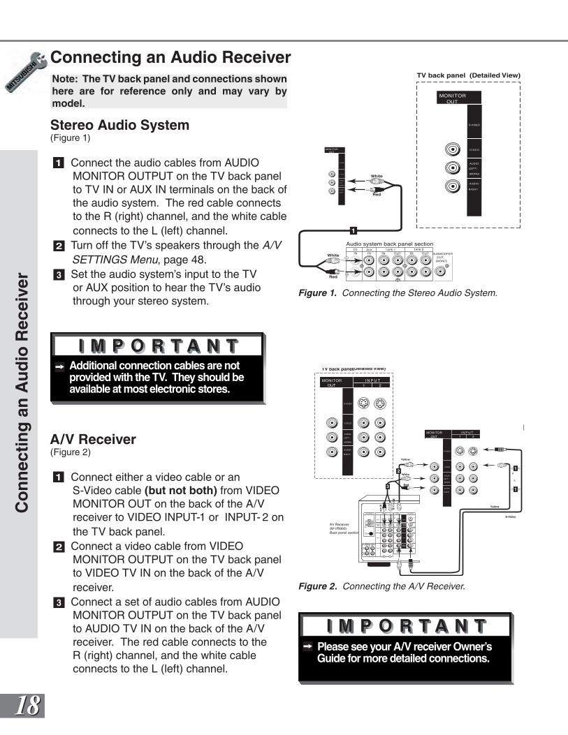
Stereo Audio System(Figure 1)
1 Connect the audio cables from AUDIO MONITOR OUTPUT on the TV back panel to TV IN or AUX IN terminals on the back of the audio system. The red cable connects to the R (right) channel, and the white cable connects to the L (left) channel.
2 Turn off the TV’s speakers through the A/V SETTINGS Menu, page 48.
3 Set the audio system’s input to the TV or AUX position to hear the TV’s audio through your stereo system.
A/V Receiver(Figure 2)
1 Connect either a video cable or an S-Video cable (but not both) from VIDEO MONITOR OUT on the back of the A/V receiver to VIDEO INPUT-1 or INPUT- 2 on the TV back panel.
2 Connect a video cable from VIDEO MONITOR OUTPUT on the TV back panel to VIDEO TV IN on the back of the A/V receiver.
3 Connect a set of audio cables from AUDIO MONITOR OUTPUT on the TV back panel to AUDIO TV IN on the back of the A/V receiver. The red cable connects to the R (right) channel, and the white cable connects to the L (left) channel.
Figure 1. Connecting the Stereo Audio System.
Figure 2. Connecting the A/V Receiver.
Note: The TV back panel and connections shown here are for reference only and may vary by model.
1919
Do not display the same stationary images on the screen for more than 15% of your total TV viewing in one week. Examples of stationary images are
letterbox top/bottom bars from DVD or other video sources, side bars when showing standard TV pictures on widescreen TV’s, stock market reports, video game patterns, station logos, web sites, or stationary computer images. Such patterns can unevenly age the picture tubes causing permanent damage to the TV. Please see pages 23 and 51 for a detailed explanation.
WARNING:
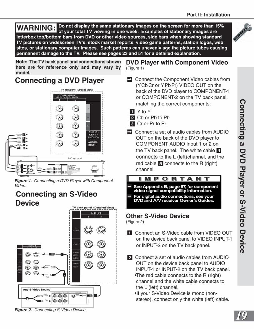
Connecting a DVD Player
DVD Player with Component Video(Figure 1)
Connect the Component Video cables from (YCb Cr or YPbPr) VIDEO OUT on the back of the DVD player to COMPONENT-1 or COMPONENT-2 on the TV back panel, matching the correct components:
1 Y to Y2 Cb or Pb to Pb3 Cr or Pr to Pr
Connect a set of audio cables from AUDIO OUT on the back of the DVD player to COMPONENT AUDIO Input 1 or 2 on the TV back panel. The white cable 4 connects to the L (left)channel, and the red cable 5 connects to the R (right) channel.
See Appendix B, page 67, for component video signal compatibility information.
For digital audio connections, see your DVD and A/V receiver Owner’s Guides.
Co
nn
ecting
a DV
D P
layer or S
-Vid
eo D
eviceI N P U T21
AUDIO-
RIGHT
AUDIO-
LEFT /
(MONO)
V I D EO
S-VIDEO
AUDIO OUT AUDIO IN VIDEO OUT
(Y/C)L
R
L
R
1 221
1
2
Any S-Video Device
I N P U T21
AUDIO-
RIGHT
AUDIO-
LEFT /
(MONO)
V I D EO
S-VIDEO
TV back panel (Detailed View)
White
Red
White
Red
Other S-Video Device(Figure 2)
1 Connect an S-Video cable from VIDEO OUT on the device back panel to VIDEO INPUT-1 or INPUT-2 on the TV back panel.
2 Connect a set of audio cables from AUDIO OUT on the device back panel to AUDIO INPUT-1 or INPUT-2 on the TV back panel. •The red cable connects to the R (right) channel and the white cable connects to the L (left) channel.•If your S-Video Device is mono (non-stereo), connect only the white (left) cable.
Connecting an S-Video Device
Figure 2. Connecting S-Video Device.
Note: The TV back panel and connections shown here are for reference only and may vary by model.
COMPONENT 480 i / 480P/ 1080i
AUDIO -
RIGHT
L E FT /( MONO)
AUDIO -
2
Y
P r
P b
VIDEO
S
Y
CB
CR
VIDEO OUT
BITSTREAM/PCM5.1 CH SURROUND 2CH
L
R
CENTER
SUBWOOFER SURROUND FRONT COAXIAL OPTICAL
AUDIO OUTAC INMITSUBISHI
DVD PLAYER
MODEL DD-5000POWER SUPPLY 120V~ 60Hz
POWER CONSUMPTION 20W
MITSUBISHI DIGITAL ELECTRONICSDISTRIBUTED BY
9351 JERONIMO ROADIRVINE, CA 92618
MADE IN JAPAN
AMERICA, INC.
SERIAL NO.
MANUFACTURED
5
4
TV back panel (Detailed View)
White
Red
White
Red
DVD back panel
2
1
1
3
5
4
2
3
Part ll: Installation
Figure 1. Connecting a DVD Player with Component Video.
2020
Co
nn
ecti
ng
a D
TV
Rec
eive
r
Connecting a DTV Receiver
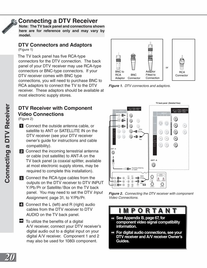
DTV Connectors and Adaptors(Figure 1)
The TV back panel has five RCA-type connectors for the DTV connection. The back panel of your DTV receiver may use RCA-type connectors or BNC-type connectors. If your DTV receiver comes with BNC type connections, you will need to purchase BNC to RCA adaptors to connect the TV to the DTV receiver. These adaptors should be available at most electronic supply stores.
DTV Receiver with Component Video Connections(Figure 2)
1 Connect the outside antenna cable, or satellite to ANT or SATELLITE IN on the
DTV receiver (see your DTV receiver owner’s guide for instructions and cable
compatibility).2 Connect the incoming terrestrial antenna
or cable (not satellite) to ANT-A on the TV back panel (a coaxial splitter, available at most electronic supply stores, may be required to complete this installation).
3 Connect the RCA-type cables from the outputs on the DTV receiver to DTV INPUT Y/Pb/Pr or Satellite / Box on the TV back panel. You may need to set the DTV Input Assignment, page 31, to Y/Pb/Pr.
4 Connect the L (left) and R (right) audio cables from the DTV receiver to DTV AUDIO on the TV back panel.
To utilize the benefits of a digital A/V receiver, connect your DTV receiver’s digital audio out to a digital input on your digital A/V receiver. Component 1 and 2 may also be used for 1080i component.
See Appendix B, page 67, for component video signal compatibility information.
For digital audio connections, see your DTV receiver and A/V receiver Owner’s Guides.
BNC toRCA BNCAdaptor Connector
AdaptorFitted toConnection
RCA Connector
or
Figure 1. DTV connectors and adaptors.
Figure 2. Connecting the DTV receiver with componentVideo Connections.
AUDIO AUDIO
VIDEO VIDEO
L
R
L
R
Y
Pr
Pb
S-VIDEO
VCRCONTROL
DIGITALAUDIO OUT
PHONE JACK
RF
REMOTE SATELLITE ININ FROM ANT
OUT TO TV
CH 3CH 4
CAUTIONRISK OF ELECTRICAL SHOCK
DO NOT OPEN
DT V (YPbPr/ GBRHV )
I N P U T21
AN T - A
480 i / 480P /1080 i
AUDIO-
RIGHT
AUDIO-
LEFT /
(MONO)
Y
G
Pb
B
P r
RV I D EO
S-VIDEO
White
Red
3
3
3
4
4
4
4
3
3
3
Incoming Antenna,or Cable.
White
Red
2
2
DT V (YPbPr/ GBRHV )
I N P U T21
AN T - A
480 i / 480P /1080 i
AUDIO-
RIGHT
AUDIO-
LEFT /
(MONO)
Y
G
Pb
B
P r
RV I D EO
S-VIDEO
TV back panel (Detailed View)
Note: The TV back panel and connections shown here are for reference only and may vary by model.
2121
Co
nn
ecting
a DT
V R
eceiver
Connecting a DTV Receiver
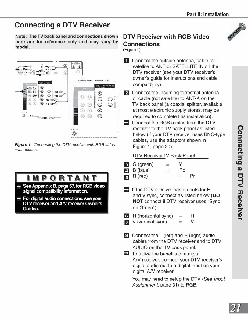
DTV Receiver with RGB Video Connections(Figure 1)
1 Connect the outside antenna, cable, or satellite to ANT or SATELLITE IN on the DTV receiver (see your DTV receiver’s owner’s guide for instructions and cable compatibility).
2 Connect the incoming terrestrial antenna or cable (not satellite) to ANT-A on the TV back panel (a coaxial splitter, available at most electronic supply stores, may be required to complete this installation).
Connect the RGB cables from the DTV receiver to the TV back panel as listed below (if your DTV receiver uses BNC-type cables, use the adaptors shown in
Figure 1, page 20):
DTV Receiver TV Back Panel
G (green) = Y B (blue) = Pb R (red) = Pr
If the DTV receiver has outputs for H and V sync, connect as listed below (DO NOT connect if DTV receiver uses “Sync on Green”):
H (horizontal sync) = H V (vertical sync) = V
8 Connect the L (left) and R (right) audio cables from the DTV receiver and to DTV AUDIO on the TV back panel.
To utilize the benefits of a digital A/V receiver, connect your DTV receiver’s digital audio out to a digital input on your digital A/V receiver.
You may need to setup the DTV (See Input Assignment, page 31) to RGB.
Figure 1. Connecting the DTV receiver with RGB video connections.
DT V (YPbPr/ GBRHV )
I N P U T21
AN T - A
480 i / 480P /1080 i
AUDIO-
RIGHT
AUDIO-
LEFT /
(MONO)
Y
G
Pb
B
P r
RV I D EO
S-VIDEO
V
H
DT V (YPbPr/ GBRHV )
I N P U T21
AN T - A
480 i / 480P /1080 i
AUDIO-
RIGHT
AUDIO-
LEFT /
(MONO)
Y
G
Pb
B
P r
RV I D EO
S-VIDEO
V
H
TV back panel (Detailed View)
AUDIO
L
R
H
V
G
R
B
S-VIDEO
VCRCONTROL
DIGITALAUDIO OUT
PHONE JACK
RF
REMOTE SATELLITE ININ FROM ANT
OUT TO TV
CH 3CH 4
CAUTIONRISK OF ELECTRICAL SHOCK
DO NOT OPEN
White
Red
4
3
5
6
7
6
7
8
8
8
8
3
4
5
2Incoming Antenna,or Cable.2
See Appendix B, page 67, for RGB video signal compatibility information.
For digital audio connections, see your DTV receiver and A/V receiver Owner’s Guides.
Note: The TV back panel and connections shown here are for reference only and may vary by model.
Part ll: Installation
34
5
6
7
2222
COMPONENT 480 i / 480P/ 1080i
AUDIO -RIGHT
L E FT /( MONO)
AUDIO -
DT V (YPbPr/ GBRHV )
MONITOR I N P U TOUT 21
AN T - A AN T- BLOO POUT
480 i / 480P /1080 i
AUDIO-
RIGHT
AUDIO-
LEFT /
(MONO)
V I D EO
S-VIDEO
2
IR EMITTER REPEATER
Y
P r
P b
V
H
Y
G
Pb
B
P r
R
Other A/V Device
1
Ferr
iteC
ore
A/V Receiver
IR EMITTER REPEATER
TV back panel (Detailed View)
D I G I T A L
S U R R O U N D
SCH
D I G I T A L
S U R R O U N D
SAH
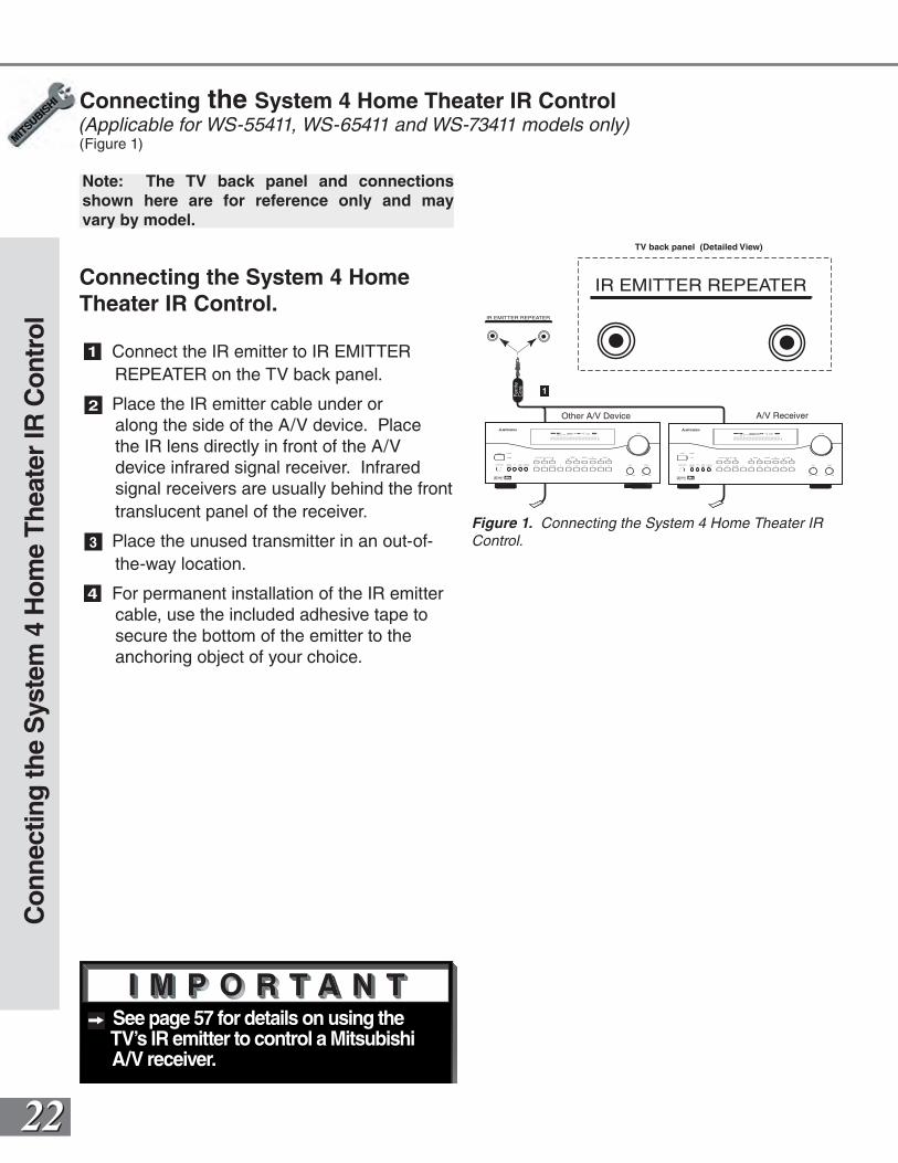
Figure 1. Connecting the System 4 Home Theater IR Control.
See page 57 for details on using the TV’s IR emitter to control a Mitsubishi A/V receiver.
1 Connect the IR emitter to IR EMITTER REPEATER on the TV back panel.
2 Place the IR emitter cable under or along the side of the A/V device. Place the IR lens directly in front of the A/V device infrared signal receiver. Infrared signal receivers are usually behind the front translucent panel of the receiver.
3 Place the unused transmitter in an out-of-the-way location.
4 For permanent installation of the IR emitter cable, use the included adhesive tape to secure the bottom of the emitter to the anchoring object of your choice.
Connecting the System 4 Home Theater IR Control(Applicable for WS-55411, WS-65411 and WS-73411 models only)(Figure 1)
Con
nect
ing
the
Sys
tem
4 H
ome
Thea
ter
IR C
ontr
ol
Connecting the System 4 Home Theater IR Control.
Note: The TV back panel and connections shown here are for reference only and may vary by model.
2323
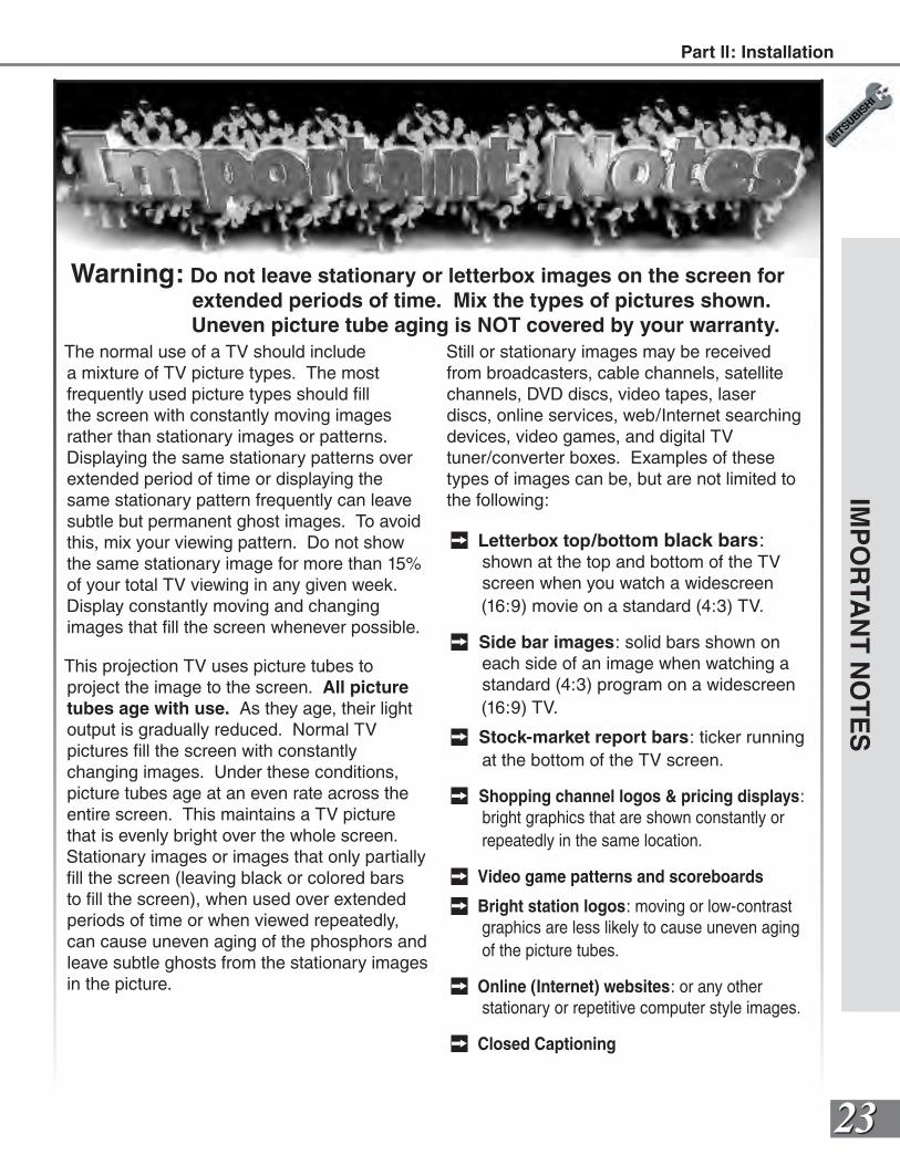
Warning: Do not leave stationary or letterbox images on the screen for extended periods of time. Mix the types of pictures shown. Uneven picture tube aging is NOT covered by your warranty.
The normal use of a TV should include a mixture of TV picture types. The most frequently used picture types should fill the screen with constantly moving images rather than stationary images or patterns. Displaying the same stationary patterns over extended period of time or displaying the same stationary pattern frequently can leave subtle but permanent ghost images. To avoid this, mix your viewing pattern. Do not show the same stationary image for more than 15% of your total TV viewing in any given week.Display constantly moving and changing images that fill the screen whenever possible.
This projection TV uses picture tubes to project the image to the screen. All picture tubes age with use. As they age, their light output is gradually reduced. Normal TV pictures fill the screen with constantly changing images. Under these conditions, picture tubes age at an even rate across the entire screen. This maintains a TV picture that is evenly bright over the whole screen. Stationary images or images that only partially fill the screen (leaving black or colored bars to fill the screen), when used over extended periods of time or when viewed repeatedly, can cause uneven aging of the phosphors and leave subtle ghosts from the stationary images in the picture.
Still or stationary images may be received from broadcasters, cable channels, satellite channels, DVD discs, video tapes, laser discs, online services, web/Internet searching devices, video games, and digital TV tuner/converter boxes. Examples of these types of images can be, but are not limited to the following:
Letterbox top/bottom black bars: shown at the top and bottom of the TV screen when you watch a widescreen (16:9) movie on a standard (4:3) TV.
Side bar images: solid bars shown on each side of an image when watching a standard (4:3) program on a widescreen (16:9) TV.
Stock-market report bars: ticker running at the bottom of the TV screen.
Shopping channel logos & pricing displays: bright graphics that are shown constantly or repeatedly in the same location.
Video game patterns and scoreboards
Bright station logos: moving or low-contrast graphics are less likely to cause uneven aging of the picture tubes.
Online (Internet) websites: or any other stationary or repetitive computer style images.
Closed Captioning
IMP
OR
TAN
T N
OT
ES
Part ll: Installation

2525
SetupUse of the Remote Control with Other A/V Products ................. 26-27
Menu System......................28
Using ...............................28
Menu Screens (Overview)... 29-30 Setup Menu..............................29 Memorize Channels ............31 Input Assignment..................31 Language...............................32 Front Button Lock.................32 Clock Setting.........................33 Captions Menu ........................35 Channel Edit Menu..................37 SQV (Super Quick View™)...39 V-Chip Lock .............................40 Lock by Time.........................42 V-Chip Hours.........................42 Passcode...............................42 Advanced Features Menu.......43 Timer ......................................43 Convergence .........................45 Color Balance........................47 Audio Video Settings Menu....48
2626
1 2
POWER
Code to enter:
To reset to default code, enter 000
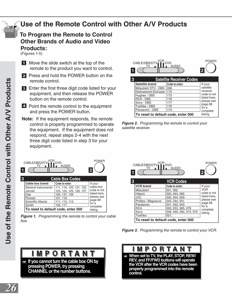
Cable box brandGeneral Instruments/JerroldOak PioneerScientific AtlantaZenith
111, 119, 120, 121, 122,123, 124, 125, 126, 127102, 137, 139101, 116 111, 112, 113 100, 117
If your cable box code is notlisted here, please see page 68for a complete listing.
Cable Box Codes3
TV AUDIOCABLE/DBS/DTV DVD
VCR
Figure 3. Programming the remote to control your VCR.
TV AUDIOCABLE/DBS/DTV DVD
VCR
1 2
POWER
Code to enter:
To reset to default code, enter 000
VCR brandMitsubishiHitachiJVCPhillips / MagnavoxPanasonicRCASonyToshiba
001, 002 020, 043, 065 030, 054, 059 043, 044, 051 041, 042, 043 020, 053, 065, 079 048, 049, 050, 074, 075 021,
If your VCR code is notlisted here, please see page 68for a complete listing.
VCR Codes3
TV AUDIOCABLE/DBS/DTV DVD
VCR
1 2
POWER
Code to enter:
To reset to default code, enter 000
Satellite brandMitsubishi DTV - DBSDishnetwork /EchostarHughes - DBSRCA - DBSSony - DBSToshiba - DBSPanasonic - DBS
006 175 173 176 177 170 174
If your satellitereceivercode is notlisted here, please see page 68for a complete listing.
Satellite Receiver Codes3
Figure 2. Programming the remote to control your satellite receiver.
If you cannot turn the cable box ON by pressing POWER, try pressing CHANNEL or the number buttons.
When set to TV, the PLAY, STOP, REW/REV, and FF/FWD buttons will operate the VCR after the VCR codes have been properly programmed into the remote control.
Figure 1. Programming the remote to control your cable box.
Use
of
the
Rem
ote
Co
ntr
ol w
ith
Oth
er A
/V P
rod
uct
s
Use of the Remote Control with Other A/V Products
To Program the Remote to Control Other Brands of Audio and Video Products:(Figures 1-5)
1 Move the slide switch at the top of the remote to the product you want to control.
2 Press and hold the POWER button on the remote control.
3 Enter the first three digit code listed for your equipment, and then release the POWER button on the remote control.
4 Point the remote control to the equipment and press the POWER button.
Note: If the equipment responds, the remote control is properly programmed to operate the equipment. If the equipment does not respond, repeat steps 2-4 with the next three digit code listed in step 3 for your equipment.
2727
TV AUDIOCABLE/DBS/DTV DVD
VCR
1 2
POWER
Code to enter:
To reset to default code, enter 000
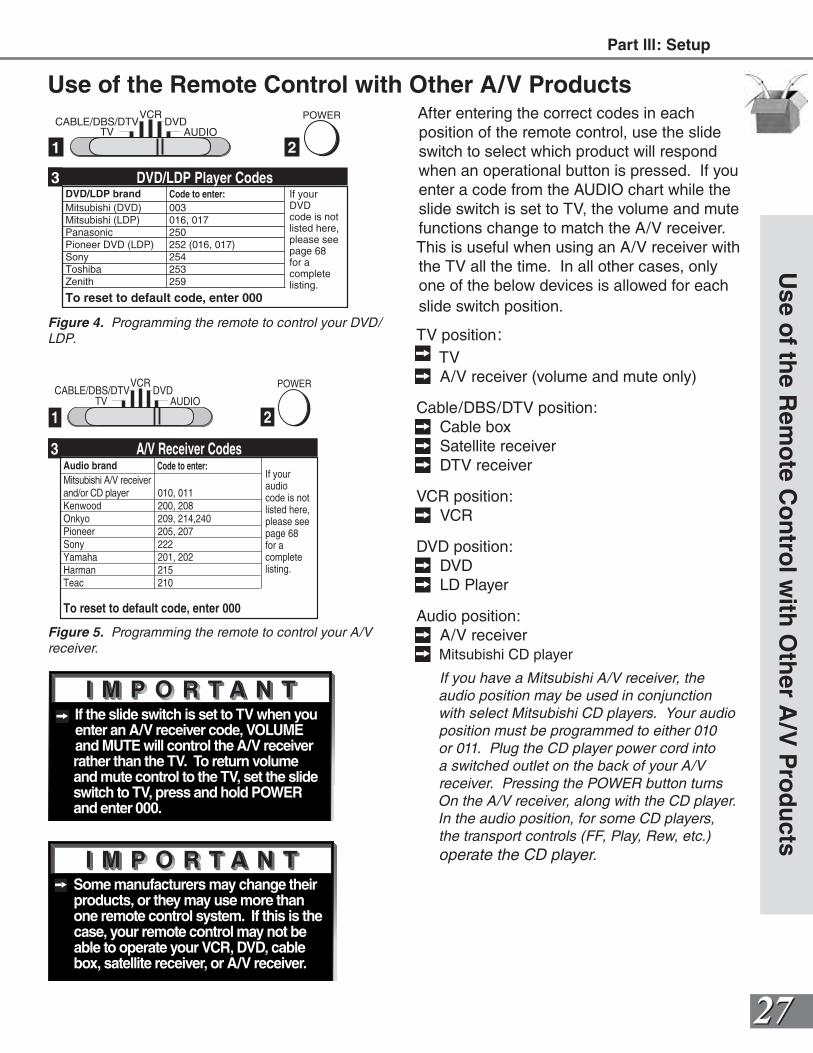
DVD/LDP brandMitsubishi (DVD)Mitsubishi (LDP)PanasonicPioneer DVD (LDP)SonyToshibaZenith
003 016, 017 250 252 (016, 017) 254 253259
If your DVD code is notlisted here, please see page 68for a complete listing.
DVD/LDP Player Codes3
TV AUDIOCABLE/DBS/DTV DVD
VCR
1 2
POWER
Code to enter:
To reset to default code, enter 000
Audio brandMitsubishi A/V receiverand/or CD playerKenwoodOnkyoPioneerSonyYamahaHarmanTeac
010, 011 200, 208 209, 214,240 205, 207 222 201, 202215 210
If your audio code is notlisted here, please see page 68for a complete listing.
A/V Receiver Codes3
If the slide switch is set to TV when you enter an A/V receiver code, VOLUME and MUTE will control the A/V receiver rather than the TV. To return volume and mute control to the TV, set the slide switch to TV, press and hold POWER and enter 000.
Some manufacturers may change their products, or they may use more than one remote control system. If this is the case, your remote control may not be able to operate your VCR, DVD, cable box, satellite receiver, or A/V receiver.
Figure 5. Programming the remote to control your A/V receiver.
Figure 4. Programming the remote to control your DVD/LDP.
Use of the Remote Control with Other A/V ProductsAfter entering the correct codes in each position of the remote control, use the slide switch to select which product will respond when an operational button is pressed. If you enter a code from the AUDIO chart while the slide switch is set to TV, the volume and mute functions change to match the A/V receiver. This is useful when using an A/V receiver with the TV all the time. In all other cases, only one of the below devices is allowed for each slide switch position.
TV position: TV A/V receiver (volume and mute only)
Cable/DBS/DTV position: Cable box Satellite receiver DTV receiver
VCR position: VCR
DVD position: DVD LD Player
Audio position: A/V receiver Mitsubishi CD player
If you have a Mitsubishi A/V receiver, the audio position may be used in conjunction with select Mitsubishi CD players. Your audio position must be programmed to either 010 or 011. Plug the CD player power cord into a switched outlet on the back of your A/V receiver. Pressing the POWER button turns On the A/V receiver, along with the CD player. In the audio position, for some CD players, the transport controls (FF, Play, Rew, etc.) operate the CD player.
Use o
f the R
emo
te Co
ntro
l with
Oth
er A/V
Pro
du
ctsPart lll: Setup
2828
POWER
INFO
PAUSEREC
FF/FWDREW/REV PLAY
STOP
3
6
9
QV
VOLUME
GUIDE
EXCH
ENTER
CANCEL MENU
V-CHIP
FORMAT
PIP CH
1
7
SQV
4
INPUT
SLEEP
VIDEO
AUDIO
MUTE
2
5
8
0
CHANNEL
ADJUST
PIP INPUT
PIP/POP
HOME
TV AUDIOCABLE/DBS DVD
VCR
234
6
7
1
Figure 2. These buttons are used for navigation within the on-screen operating system.
8
5
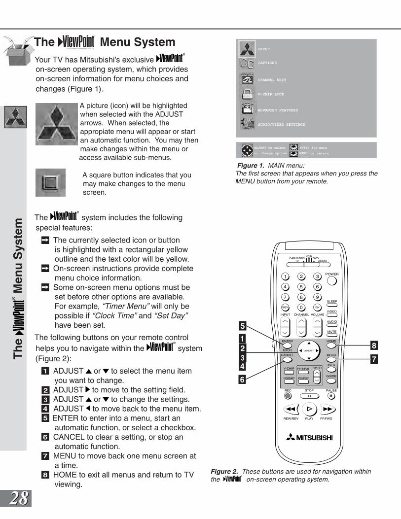
The Menu SystemYour TV has Mitsubishi’s exclusive on-screen operating system, which provides on-screen information for menu choices and changes (Figure 1).
A picture (icon) will be highlighted when selected with the ADJUST arrows. When selected, the appropiate menu will appear or start an automatic function. You may then make changes within the menu or
access available sub-menus.
A square button indicates that you may make changes to the menu screen.
The system includes the following special features:
The currently selected icon or button is highlighted with a rectangular yellow outline and the text color will be yellow.
On-screen instructions provide complete menu choice information.
Some on-screen menu options must be set before other options are available. For example, “Timer Menu” will only be possible if “Clock Time” and “Set Day” have been set.
The following buttons on your remote control helps you to navigate within the system (Figure 2):
1 ADJUST or to select the menu item you want to change.
2 ADJUST to move to the setting field.3 ADJUST or to change the settings.4 ADJUST to move back to the menu item. ENTER to enter into a menu, start an
automatic function, or select a checkbox.6 CANCEL to clear a setting, or stop an
automatic function.7 MENU to move back one menu screen at
a time.8 HOME to exit all menus and return to TV
viewing.
Th
e M
enu
Sys
tem
ENTER for menu or to start
MENU to return
SETUP
CAPTIONS
CHANNEL EDIT
V-CHIP LOCK
ADVANCED FEATURES
AUDIO/VIDEO SETTINGS
or change option
ENTER for menu
MENU to return
ADJUST to select
5
Figure 1. MAIN menu: The first screen that appears when you press the MENU button from your remote.
2929
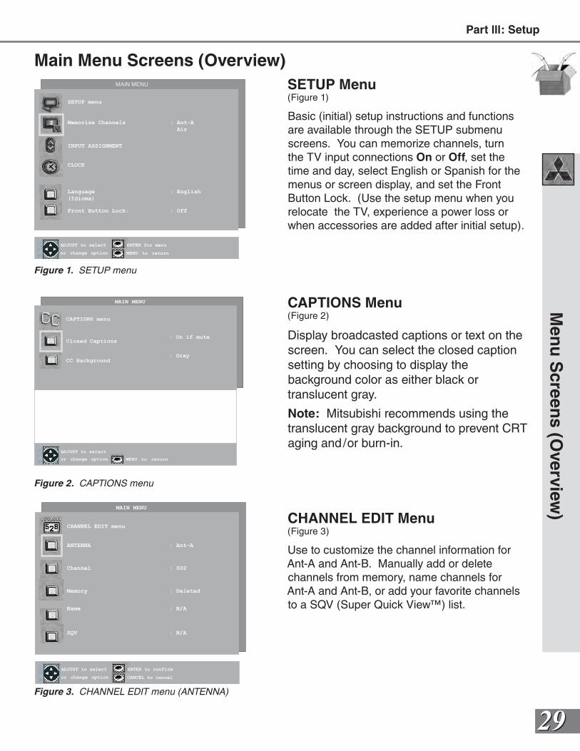
Main Menu Screens (Overview)SETUP Menu(Figure 1)
Basic (initial) setup instructions and functions are available through the SETUP submenu screens. You can memorize channels, turn the TV input connections On or Off, set the time and day, select English or Spanish for the menus or screen display, and set the Front Button Lock. (Use the setup menu when you relocate the TV, experience a power loss or when accessories are added after initial setup).
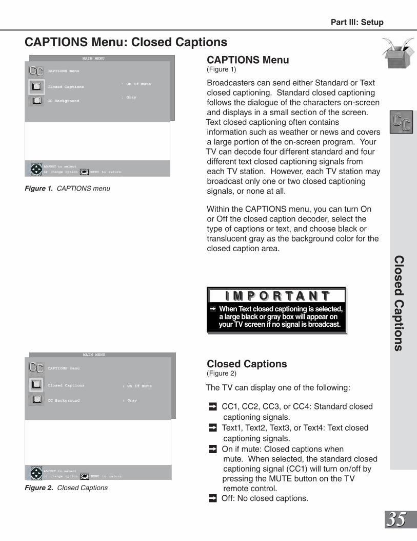
CAPTIONS Menu(Figure 2)
Display broadcasted captions or text on the screen. You can select the closed caption setting by choosing to display the background color as either black or translucent gray.
Note: Mitsubishi recommends using the translucent gray background to prevent CRT aging and/or burn-in.
Men
u S
creens (O
verview)
ENTER for menu or to start
MENU to return
CAPTIONS menu
Closed Captions
CC Background
or change option MENU to return
ADJUST to select
: On if mute
: Gray
MAIN MENU
Figure 2. CAPTIONS menu
ENTER for menu or to start
MENU to return
SETUP menu
Memorize Channels : Ant-A
Air
INPUT ASSIGNMENT
CLOCK
Language : English
(Idioma)
Front Button Lock: : Off
or change option
ENTER for menu
MENU to return
ADJUST to select
MAIN MENU
Figure 1. SETUP menu
ENTER for menu or to start
MENU to returnor change option
ENTER to confirm
CANCEL to cancel
ADJUST to select
MAIN MENU
CHANNEL EDIT menu
ANTENNA : Ant-A
Channel : 002
Memory : Deleted
Name : N/A
SQV : N/A
Figure 3. CHANNEL EDIT menu (ANTENNA)
CHANNEL EDIT Menu(Figure 3)
Use to customize the channel information for Ant-A and Ant-B. Manually add or delete channels from memory, name channels for Ant-A and Ant-B, or add your favorite channels to a SQV (Super Quick View™) list.
Part lll: Setup
3030
Main Menu Screens (Overview)
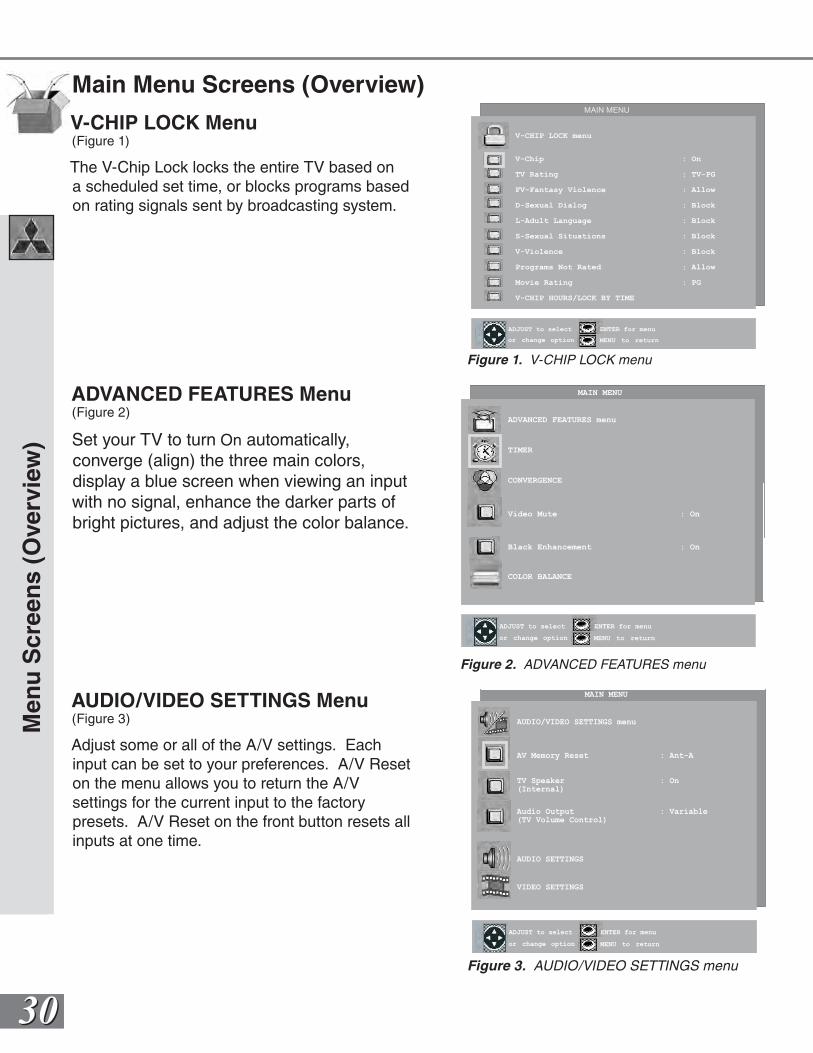
ADVANCED FEATURES Menu(Figure 2)
Set your TV to turn On automatically, converge (align) the three main colors, display a blue screen when viewing an input with no signal, enhance the darker parts of bright pictures, and adjust the color balance.
AUDIO/VIDEO SETTINGS Menu(Figure 3)
Adjust some or all of the A/V settings. Each input can be set to your preferences. A/V Reset on the menu allows you to return the A/Vsettings for the current input to the factory presets. A/V Reset on the front button resets all inputs at one time.
Men
u S
cree
ns
(Ove
rvie
w)
ENTER for menu or to start
MENU to returnor change option
ENTER for menu
MENU to return
ADJUST to select
MAIN MENU
AUDIO/VIDEO SETTINGS menu
AV Memory Reset : Ant-A
TV Speaker : On(Internal)
Audio Output : Variable(TV Volume Control)
AUDIO SETTINGS
VIDEO SETTINGS
Figure 3. AUDIO/VIDEO SETTINGS menu
ENTER for menu or to start
MENU to returnor change option
ENTER for menu
MENU to return
ADJUST to select
MAIN MENU
ADVANCED FEATURES menu
TIMER
CONVERGENCE
Video Mute : On
Black Enhancement : On
COLOR BALANCE
ENTER for menu or to start
MENU to returnor change option
ENTER for menu
MENU to return
ADJUST to select
MAIN MENU
V-CHIP LOCK menu
V-Chip : On
TV Rating : TV-PG
FV-Fantasy Violence : Allow
D-Sexual Dialog : Block
L-Adult Language : Block
S-Sexual Situations : Block
V-Violence : Block
Programs Not Rated : Allow
Movie Rating : PG
V-CHIP HOURS/LOCK BY TIME
Figure 1. V-CHIP LOCK menu
V-CHIP LOCK Menu(Figure 1)
The V-Chip Lock locks the entire TV based on a scheduled set time, or blocks programs based on rating signals sent by broadcasting system.
Figure 2. ADVANCED FEATURES menu
3131
ENTER for menu or to start
MENU to return
SETUP MENU
MEMORIZE menu
Memorize Channels : 002In Memory
Now memorizingall the stationsyou can receiveon Ant-A Air.Please stand by.
CANCEL to cancel memorization
MAIN MENU
PIP
SETUP Menu: Memorize Channels/INPUT ASSIGNMENT
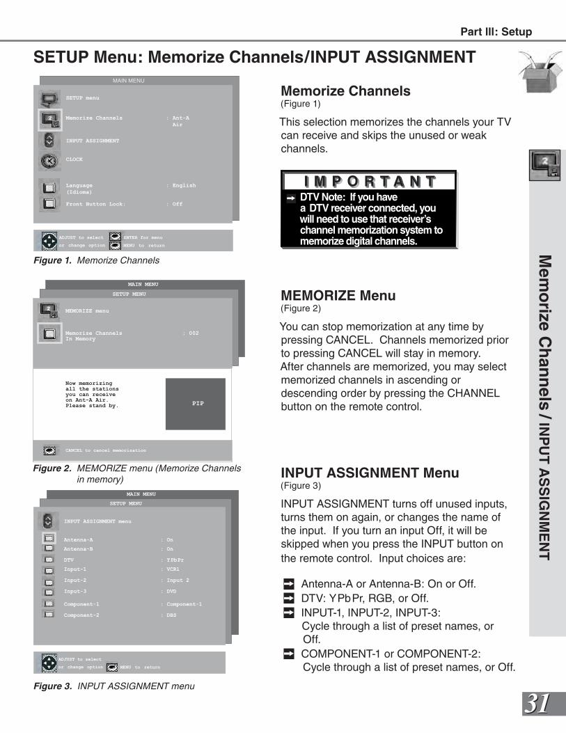
Memorize Channels(Figure 1)
This selection memorizes the channels your TV can receive and skips the unused or weak channels.
MEMORIZE Menu(Figure 2)
You can stop memorization at any time by pressing CANCEL. Channels memorized prior to pressing CANCEL will stay in memory. After channels are memorized, you may select memorized channels in ascending or descending order by pressing the CHANNEL button on the remote control.
Figure 3. AUDIO/VIDEO SETTINGS menu
ENTER for menu or to start
MENU to return
SETUP menu
Memorize Channels : Ant-A
Air
INPUT ASSIGNMENT
CLOCK
Language : English
(Idioma)
Front Button Lock: : Off
or change option
ENTER for menu
MENU to return
ADJUST to select
MAIN MENU
Figure 1. Memorize Channels
INPUT ASSIGNMENT Menu(Figure 3)
INPUT ASSIGNMENT turns off unused inputs, turns them on again, or changes the name of the input. If you turn an input Off, it will be skipped when you press the INPUT button on the remote control. Input choices are:
Antenna-A or Antenna-B: On or Off. DTV: YPbPr, RGB, or Off. INPUT-1, INPUT-2, INPUT-3:
Cycle through a list of preset names, or Off.
COMPONENT-1 or COMPONENT-2: Cycle through a list of preset names, or Off.
MAIN MENU
ENTER for menu or to start
MENU to returnor change option MENU to return
ADJUST to select
SETUP MENU
INPUT ASSIGNMENT menu
Antenna-A : On
Antenna-B : On
DTV : YPbPr
Input-1 : VCR1
Input-2 : Input 2
Input-3 : DVD
Component-1 : Component-1
Component-2 : DBS
ENTER for menu or to start
MENU to return
SETUP MENU
MEMORIZE menu
Memorize Channels : 002In Memory
Now memorizingall the stationsyou can receiveon Ant-A Air.Please stand by.
CANCEL to cancel memorization
MAIN MENU
PIP
Figure 2. MEMORIZE menu (Memorize Channels in memory)
Figure 3. INPUT ASSIGNMENT menu
DTV Note: If you have a DTV receiver connected, you will need to use that receiver’s channel memorization system to memorize digital channels.
Part lll: SetupM
emo
rize Ch
ann
els/
INP
UT
AS
SIG
NM
EN
T
3232
SETUP Menu: Language / Front Button Lock
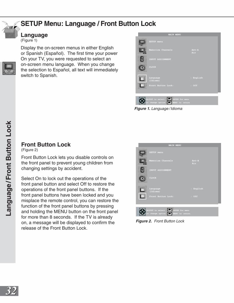
Language(Figure 1)
Display the on-screen menus in either English or Spanish (Español). The first time your power On your TV, you were requested to select an on-screen menu language. When you change the selection to Español, all text will immediately switch to Spanish.
Lan
gu
age
/Fro
nt
Bu
tto
n L
ock
ENTER for menu or to start
MENU to return
SETUP menu
Memorize Channels Ant-A
Air
INPUT ASSIGNMENT
CLOCK
Language : English
(Idioma)
Front Button Lock: : Off
or change option
ENTER for menu
MENU to return
ADJUST to select
MAIN MENU
Figure 1. Language / Idioma
ENTER for menu or to start
MENU to return
SETUP menu
Memorize Channels Ant-A
Air
INPUT ASSIGNMENT
CLOCK
Language : English
(Idioma)
Front Button Lock: : Off
or change option
ENTER for menu
MENU to return
ADJUST to select
MAIN MENU
Figure 2. Front Button Lock
Front Button Lock(Figure 2)
Front Button Lock lets you disable controls on the front panel to prevent young children from changing settings by accident.
Select On to lock out the operations of the front panel button and select Off to restore the operations of the front panel buttons. If the front panel buttons have been locked and you misplace the remote control, you can restore the function of the front panel buttons by pressing and holding the MENU button on the front panel for more than 8 seconds. If the TV is already on, a message will be displayed to confirm the release of the Front Button Lock.
3333
CLOCK Menu: Clock Setting / Tme Zone / D.S.T.
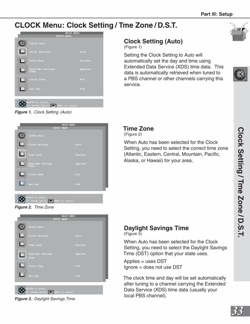
Clock Setting (Auto)(Figure 1)
Setting the Clock Setting to Auto will automatically set the day and time using Extended Data Service (XDS) time data. This data is automatically retrieved when tuned to a PBS channel or other channels carrying this service.
Time Zone(Figure 2)
When Auto has been selected for the Clock Setting, you need to select the correct time zone (Atlantic, Eastern, Central, Mountain, Pacific, Alaska, or Hawaii) for your area.
Daylight Savings Time(Figure 3)
When Auto has been selected for the Clock Setting, you need to select the Daylight Savings Time (DST) option that your state uses.
Applies = uses DSTIgnore = does not use DST
The clock time and day will be set automatically after tuning to a channel carrying the Extended Data Service (XDS) time data (usually your local PBS channel).
MAIN MENU
ENTER for menu or to start
MENU to return
CLOCK menu
Clock Setting : Auto
Time Zone : Eastern
Daylight Savings : Applies
Time
Clock Time : N/A
Set Day : N/A
or change option MENU to return
ADJUST to select
SETUP MENU
Figure 3. Daylight Savings Time
MAIN MENU
ENTER for menu or to start
MENU to return
CLOCK menu
Clock Setting : Auto
Time Zone : Eastern
Daylight Savings : AppliesTime
Clock Time : N/A
Set Day : N/A
or change option MENU to return
ADJUST to select
SETUP MENU
Figure 2. Time Zone
MAIN MENU
ENTER for menu or to start
MENU to return
CLOCK menu
Clock Setting : Auto
Time Zone : Eastern
Daylight Savings : AppliesTime
Clock Time : N/A
Set Day : N/A
or change option MENU to return
ADJUST to select
SETUP MENU
Figure 1. Clock Setting (Auto)
Clo
ck Settin
g/Tm
e Zo
ne
/D.S
.T.Part lll: Setup
3434
Clock Menu: Clock Time / Set Day
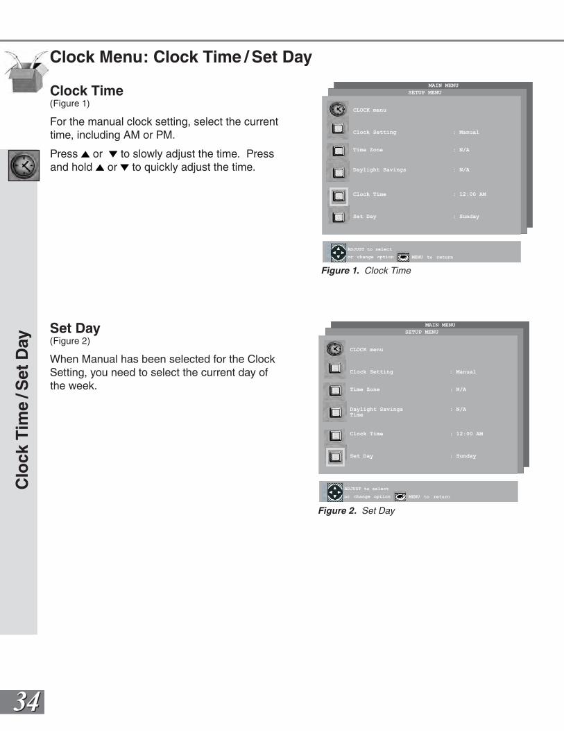
Clock Time(Figure 1)
For the manual clock setting, select the current time, including AM or PM.
Press or to slowly adjust the time. Press and hold or to quickly adjust the time.
Set Day(Figure 2)
When Manual has been selected for the Clock Setting, you need to select the current day of the week.
MAIN MENU
ENTER for menu or to start
MENU to return
CLOCK menu
Clock Setting : Manual
Time Zone : N/A
Daylight Savings : N/ATime
Clock Time : 12:00 AM
Set Day : Sunday
or change option MENU to return
ADJUST to select
SETUP MENU
Figure 2. Set Day
MAIN MENU
ENTER for menu or to start
MENU to return
CLOCK menu
Clock Setting : Manual
Time Zone : N/A
Daylight Savings : N/A
Clock Time : 12:00 AM
Set Day : Sunday
or change option MENU to return
ADJUST to select
SETUP MENU
Figure 1. Clock Time
Clo
ck T
ime
/Set
Day
3535
When Text closed captioning is selected, a large black or gray box will appear on your TV screen if no signal is broadcast.
CAPTIONS Menu: Closed CaptionsCAPTIONS Menu(Figure 1)
Broadcasters can send either Standard or Text closed captioning. Standard closed captioning follows the dialogue of the characters on-screen and displays in a small section of the screen. Text closed captioning often contains information such as weather or news and covers a large portion of the on-screen program. Your TV can decode four different standard and four different text closed captioning signals from each TV station. However, each TV station may broadcast only one or two closed captioning signals, or none at all.
Within the CAPTIONS menu, you can turn On or Off the closed caption decoder, select the type of captions or text, and choose black or translucent gray as the background color for the closed caption area.
Closed Captions(Figure 2)
The TV can display one of the following:
CC1, CC2, CC3, or CC4: Standard closed captioning signals.
Text1, Text2, Text3, or Text4: Text closed captioning signals.
On if mute: Closed captions when mute. When selected, the standard closed captioning signal (CC1) will turn on/off by
pressing the MUTE button on the TV remote control.
Off: No closed captions.
Clo
sed C
aptio
ns
ENTER for menu or to start
MENU to return
CAPTIONS menu
Closed Captions
CC Background
or change option MENU to return
ADJUST to select
: On if mute
: Gray
MAIN MENU
Figure 2. Closed Captions
ENTER for menu or to start
MENU to return
CAPTIONS menu
Closed Captions
CC Background
or change option MENU to return
ADJUST to select
: On if mute
: Gray
MAIN MENU
Figure 1. CAPTIONS menu
Part lll: Setup
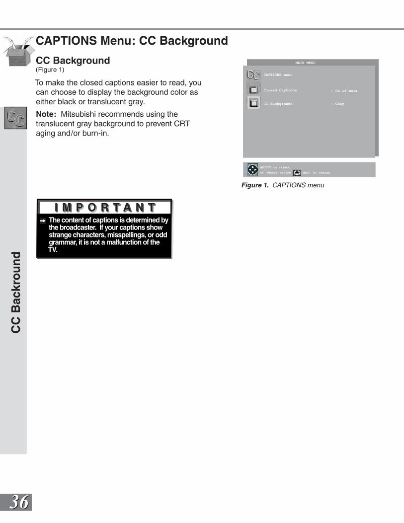
3636
The content of captions is determined by the broadcaster. If your captions show strange characters, misspellings, or odd grammar, it is not a malfunction of the TV.
CAPTIONS Menu: CC Background
CC
Bac
kro
un
d
ENTER for menu or to start
MENU to return
CAPTIONS menu
Closed Captions
CC Background
or change option MENU to return
ADJUST to select
: On if mute
: Gray
MAIN MENU
Figure 1. CAPTIONS menu
CC Background(Figure 1)
To make the closed captions easier to read, you can choose to display the background color as either black or translucent gray.
Note: Mitsubishi recommends using the translucent gray background to prevent CRT aging and/or burn-in.
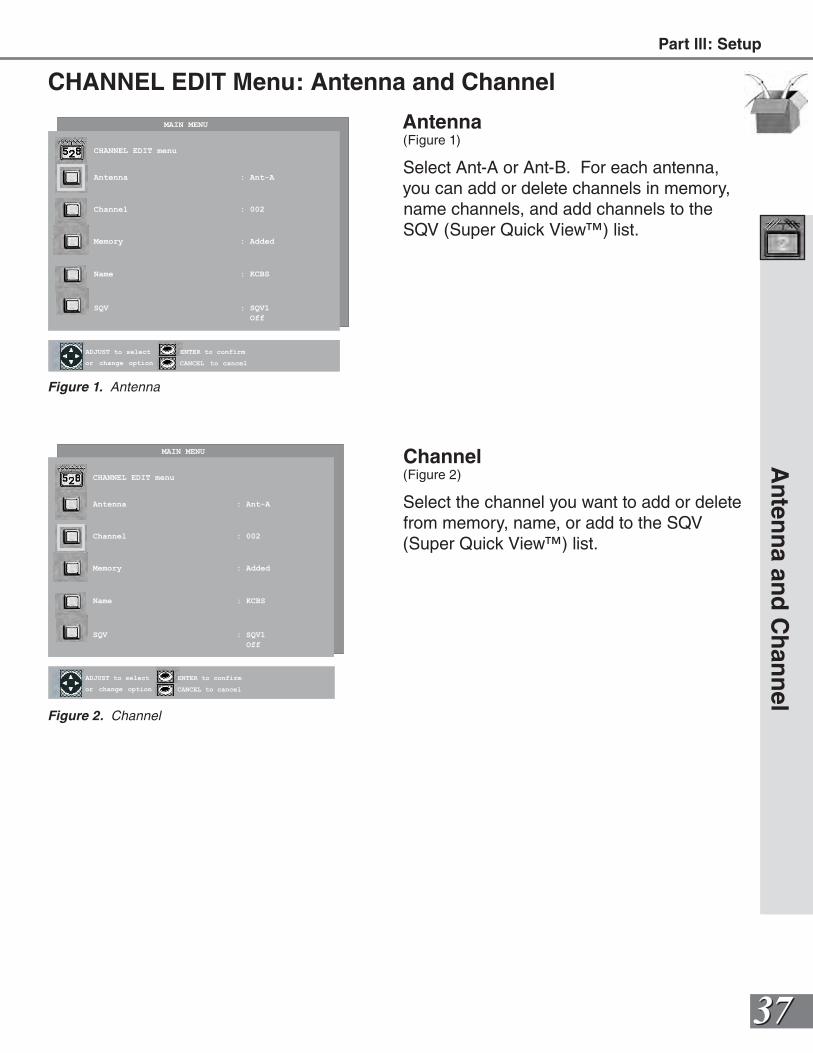
3737
Antenna(Figure 1)
Select Ant-A or Ant-B. For each antenna, you can add or delete channels in memory, name channels, and add channels to the SQV (Super Quick View™) list.
Channel(Figure 2)
Select the channel you want to add or delete from memory, name, or add to the SQV (Super Quick View™) list.
CHANNEL EDIT Menu: Antenna and Channel
An
tenn
a and
Ch
ann
el
ENTER for menu or to start
MENU to returnor change option
ENTER to confirm
CANCEL to cancel
ADJUST to select
MAIN MENU
CHANNEL EDIT menu
Antenna : Ant-A
Channel : 002
Memory : Added
Name : KCBS
SQV : SQV1
Off
Figure 2. Channel
ENTER for menu or to start
MENU to returnor change option
ENTER to confirm
CANCEL to cancel
ADJUST to select
MAIN MENU
CHANNEL EDIT menu
Antenna : Ant-A
Channel : 002
Memory : Added
Name : KCBS
SQV : SQV1
Off
Figure 1. AntennaFigure 1. CAPTIONS menu
Part lll: Setup
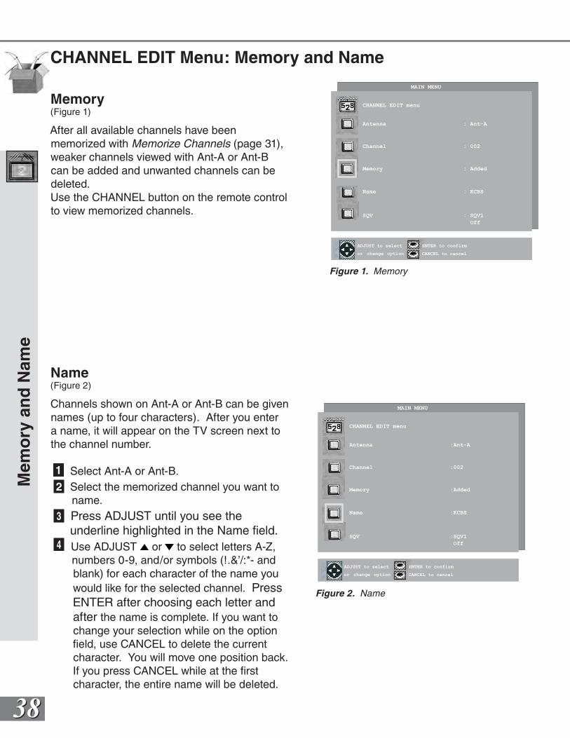
3838
Name(Figure 2)
Channels shown on Ant-A or Ant-B can be given names (up to four characters). After you enter a name, it will appear on the TV screen next to the channel number.
1 Select Ant-A or Ant-B.2 Select the memorized channel you want to name.3 Press ADJUST until you see the
underline highlighted in the Name field.4 Use ADJUST or to select letters A-Z,
numbers 0-9, and/or symbols (!.&’/:*- and blank) for each character of the name you would like for the selected channel. Press ENTER after choosing each letter and after the name is complete. If you want to change your selection while on the option field, use CANCEL to delete the current character. You will move one position back. If you press CANCEL while at the first character, the entire name will be deleted.
Memory(Figure 1)
After all available channels have been memorized with Memorize Channels (page 31), weaker channels viewed with Ant-A or Ant-B can be added and unwanted channels can be deleted.Use the CHANNEL button on the remote control to view memorized channels.
CHANNEL EDIT Menu: Memory and Name
Mem
ory
an
d N
ame
ENTER for menu or to start
MENU to returnor change option
ENTER to confirm
CANCEL to cancel
ADJUST to select
MAIN MENU
CHANNEL EDIT menu
Antenna :Ant-A
Channel :002
Memory :Added
Name :KCBS
SQV :SQV1
Off
Figure 2. Name
ENTER for menu or to start
MENU to returnor change option
ENTER to confirm
CANCEL to cancel
ADJUST to select
MAIN MENU
CHANNEL EDIT menu
Antenna : Ant-A
Channel : 002
Memory : Added
Name : KCBS
SQV : SQV1
Off
Figure 1. Memory
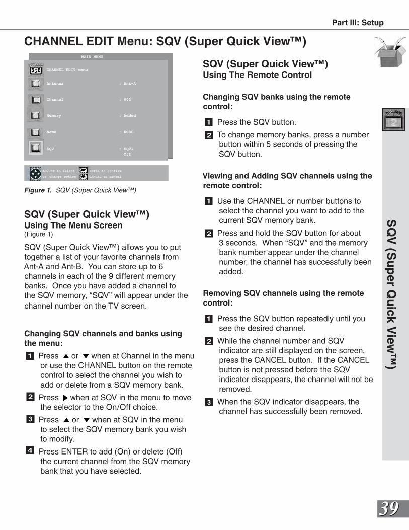
3939
CHANNEL EDIT Menu: SQV (Super Quick View™)
SQV (Super Quick View™)Using The Menu Screen(Figure 1)
SQV (Super Quick View™) allows you to put together a list of your favorite channels from Ant-A and Ant-B. You can store up to 6 channels in each of the 9 different memory banks. Once you have added a channel to the SQV memory, “SQV” will appear under the channel number on the TV screen.
Changing SQV channels and banks using the menu:
1 Press or when at Channel in the menu or use the CHANNEL button on the remote control to select the channel you wish to add or delete from a SQV memory bank.
2 Press when at SQV in the menu to move the selector to the On/Off choice.
3 Press or when at SQV in the menu to select the SQV memory bank you wish to modify.
4 Press ENTER to add (On) or delete (Off) the current channel from the SQV memory bank that you have selected.
SQ
V (S
up
er Qu
ick View
™)
ENTER for menu or to start
MENU to returnor change option
ENTER to confirm
CANCEL to cancel
ADJUST to select
MAIN MENU
CHANNEL EDIT menu
Antenna : Ant-A
Channel : 002
Memory : Added
Name : KCBS
SQV : SQV1
Off
Figure 1. SQV (Super Quick View™)
SQV (Super Quick View™)Using The Remote Control
Changing SQV banks using the remote control:
1 Press the SQV button.
2 To change memory banks, press a number button within 5 seconds of pressing the SQV button.
Viewing and Adding SQV channels using the remote control:
1 Use the CHANNEL or number buttons to select the channel you want to add to the current SQV memory bank.
2 Press and hold the SQV button for about 3 seconds. When “SQV” and the memory bank number appear under the channel number, the channel has successfully been added.
Removing SQV channels using the remote control:
1 Press the SQV button repeatedly until you see the desired channel.
2 While the channel number and SQV indicator are still displayed on the screen, press the CANCEL button. If the CANCEL button is not pressed before the SQV indicator disappears, the channel will not be removed.
3 When the SQV indicator disappears, the channel has successfully been removed.
Part lll: Setup
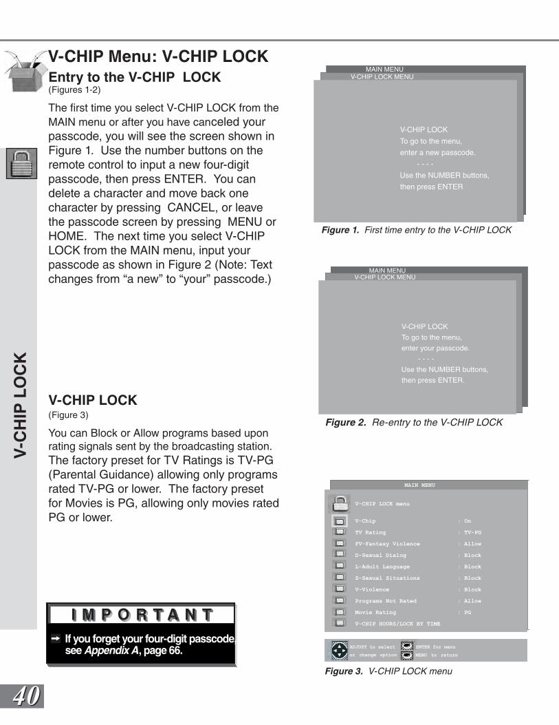
4040
If you forget your four-digit passcode, see Appendix A, page 66.
V-CHIP Menu: V-CHIP LOCK
V-C
HIP
LO
CK
V-CHIP LOCK To go to the menu,
enter a new passcode.
- - - -
Use the NUMBER buttons,
then press ENTER
V-CHIP LOCK MENUMAIN MENU
Figure 1. First time entry to the V-CHIP LOCK
ENTER for menu or to start
MENU to returnor change option
ENTER for menu
MENU to return
ADJUST to select
MAIN MENU
V-CHIP LOCK menu
V-Chip : On
TV Rating : TV-PG
FV-Fantasy Violence : Allow
D-Sexual Dialog : Block
L-Adult Language : Block
S-Sexual Situations : Block
V-Violence : Block
Programs Not Rated : Allow
Movie Rating : PG
V-CHIP HOURS/LOCK BY TIME
V-CHIP LOCK MENUMAIN MENU
V-CHIP LOCK To go to the menu,
enter your passcode.
- - - -
Use the NUMBER buttons,
then press ENTER.
Figure 2. Re-entry to the V-CHIP LOCK
V-CHIP LOCK(Figure 3)
You can Block or Allow programs based upon rating signals sent by the broadcasting station. The factory preset for TV Ratings is TV-PG (Parental Guidance) allowing only programs rated TV-PG or lower. The factory preset for Movies is PG, allowing only movies rated PG or lower.
Entry to the V-CHIP LOCK(Figures 1-2)
The first time you select V-CHIP LOCK from the MAIN menu or after you have canceled your passcode, you will see the screen shown in Figure 1. Use the number buttons on the remote control to input a new four-digitpasscode, then press ENTER. You can delete a character and move back one character by pressing CANCEL, or leave the passcode screen by pressing MENU or HOME. The next time you select V-CHIP LOCK from the MAIN menu, input your passcode as shown in Figure 2 (Note: Text changes from “a new” to “your” passcode.)
Figure 3. V-CHIP LOCK menu
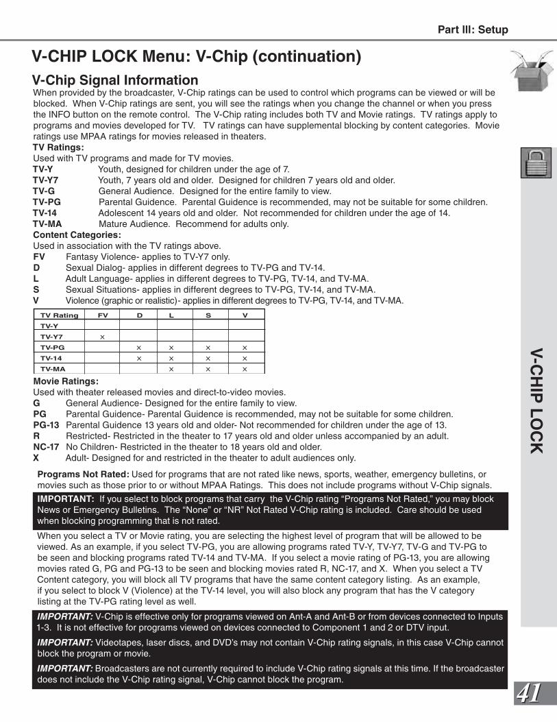
4141
V-C
HIP
LOC
K
Figure 2. Re-entry to the V-CHIP LOCK
TV Rating FV D L S V
TV-Y
TV-Y7 X
TV-PG X X X X
TV-14 X X X X
TV-MA X X X
V-CHIP LOCK Menu: V-Chip (continuation)V-Chip Signal Information When provided by the broadcaster, V-Chip ratings can be used to control which programs can be viewed or will be blocked. When V-Chip ratings are sent, you will see the ratings when you change the channel or when you press the INFO button on the remote control. The V-Chip rating includes both TV and Movie ratings. TV ratings apply to programs and movies developed for TV. TV ratings can have supplemental blocking by content categories. Movie ratings use MPAA ratings for movies released in theaters.TV Ratings:Used with TV programs and made for TV movies.TV-Y Youth, designed for children under the age of 7.TV-Y7 Youth, 7 years old and older. Designed for children 7 years old and older.TV-G General Audience. Designed for the entire family to view.TV-PG Parental Guidence. Parental Guidence is recommended, may not be suitable for some children.TV-14 Adolescent 14 years old and older. Not recommended for children under the age of 14.TV-MA Mature Audience. Recommend for adults only.Content Categories:Used in association with the TV ratings above.FV Fantasy Violence- applies to TV-Y7 only.D Sexual Dialog- applies in different degrees to TV-PG and TV-14.L Adult Language- applies in different degrees to TV-PG, TV-14, and TV-MA.S Sexual Situations- applies in different degrees to TV-PG, TV-14, and TV-MA.V Violence (graphic or realistic)- applies in different degrees to TV-PG, TV-14, and TV-MA.
Movie Ratings:Used with theater released movies and direct-to-video movies.G General Audience- Designed for the entire family to view.PG Parental Guidence- Parental Guidence is recommended, may not be suitable for some children.PG-13 Parental Guidence 13 years old and older- Not recommended for children under the age of 13.R Restricted- Restricted in the theater to 17 years old and older unless accompanied by an adult.NC-17 No Children- Restricted in the theater to 18 years old and older.X Adult- Designed for and restricted in the theater to adult audiences only.
Programs Not Rated: Used for programs that are not rated like news, sports, weather, emergency bulletins, or movies such as those prior to or without MPAA Ratings. This does not include programs without V-Chip signals.
IMPORTANT: If you select to block programs that carry the V-Chip rating “Programs Not Rated,” you may block News or Emergency Bulletins. The “None” or “NR” Not Rated V-Chip rating is included. Care should be used when blocking programming that is not rated.
When you select a TV or Movie rating, you are selecting the highest level of program that will be allowed to be viewed. As an example, if you select TV-PG, you are allowing programs rated TV-Y, TV-Y7, TV-G and TV-PG to be seen and blocking programs rated TV-14 and TV-MA. If you select a movie rating of PG-13, you are allowing movies rated G, PG and PG-13 to be seen and blocking movies rated R, NC-17, and X. When you select a TV Content category, you will block all TV programs that have the same content category listing. As an example, if you select to block V (Violence) at the TV-14 level, you will also block any program that has the V category listing at the TV-PG rating level as well.
IMPORTANT: V-Chip is effective only for programs viewed on Ant-A and Ant-B or from devices connected to Inputs 1-3. It is not effective for programs viewed on devices connected to Component 1 and 2 or DTV input.
IMPORTANT: Videotapes, laser discs, and DVD’s may not contain V-Chip rating signals, in this case V-Chip cannot block the program or movie.
IMPORTANT: Broadcasters are not currently required to include V-Chip rating signals at this time. If the broadcaster does not include the V-Chip rating signal, V-Chip cannot block the program.
Part lll: Setup
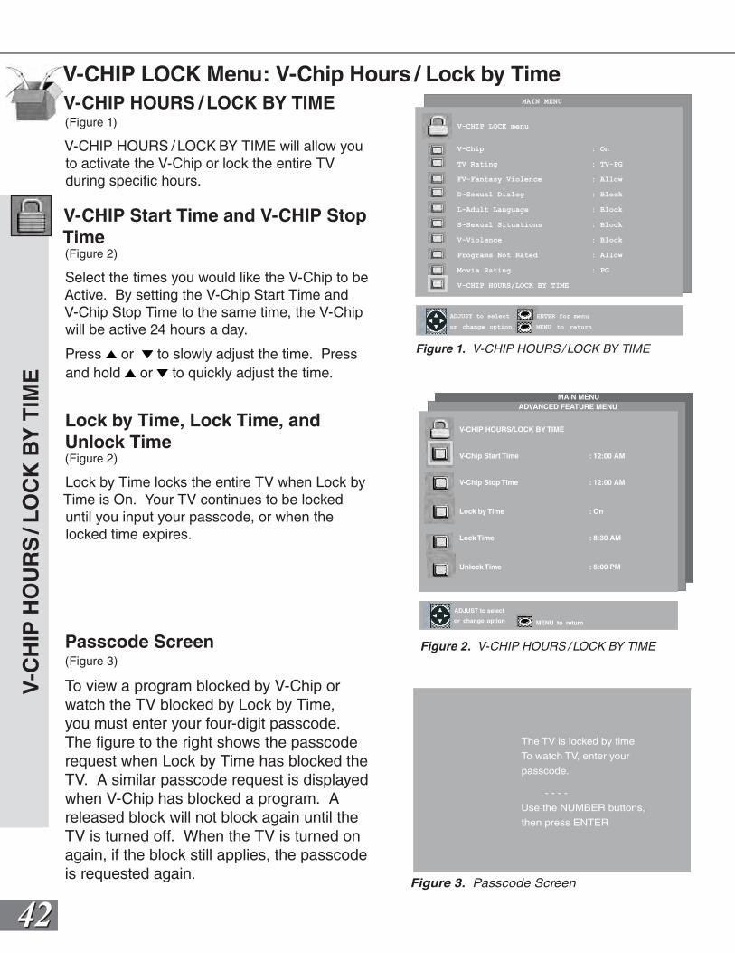
4242
V-CHIP LOCK Menu: V-Chip Hours / Lock by TimeV-CHIP HOURS / LOCK BY TIME(Figure 1)
V-CHIP HOURS / LOCK BY TIME will allow you to activate the V-Chip or lock the entire TV during specific hours.
V-CHIP Start Time and V-CHIP Stop Time(Figure 2)
Select the times you would like the V-Chip to be Active. By setting the V-Chip Start Time and V-Chip Stop Time to the same time, the V-Chip will be active 24 hours a day.
Press or to slowly adjust the time. Press and hold or to quickly adjust the time.
Lock by Time, Lock Time, and Unlock Time(Figure 2)
Lock by Time locks the entire TV when Lock by Time is On. Your TV continues to be locked until you input your passcode, or when the locked time expires.
V-C
HIP
HO
UR
S/L
OC
K B
Y T
IME
The TV is locked by time.
To watch TV, enter your
passcode.
- - - -
Use the NUMBER buttons,
then press ENTER
Figure 3. Passcode Screen
ENTER for menu or to start
MENU to return
V-CHIP HOURS/LOCK BY TIME
V-Chip Start Time : 12:00 AM
V-Chip Stop Time : 12:00 AM
Lock by Time : On
Lock Time : 8:30 AM
Unlock Time : 6:00 PM
ADVANCED FEATURE MENU
or change option MENU to return
ADJUST to select
MAIN MENU
Figure 2. V-CHIP HOURS / LOCK BY TIME
ENTER for menu or to start
MENU to returnor change option
ENTER for menu
MENU to return
ADJUST to select
MAIN MENU
V-CHIP LOCK menu
V-Chip : On
TV Rating : TV-PG
FV-Fantasy Violence : Allow
D-Sexual Dialog : Block
L-Adult Language : Block
S-Sexual Situations : Block
V-Violence : Block
Programs Not Rated : Allow
Movie Rating : PG
V-CHIP HOURS/LOCK BY TIME
Figure 1. V-CHIP HOURS/ LOCK BY TIME
Passcode Screen(Figure 3)
To view a program blocked by V-Chip or watch the TV blocked by Lock by Time, you must enter your four-digit passcode. The figure to the right shows the passcode request when Lock by Time has blocked the TV. A similar passcode request is displayed when V-Chip has blocked a program. A released block will not block again until the TV is turned off. When the TV is turned on again, if the block still applies, the passcode is requested again.
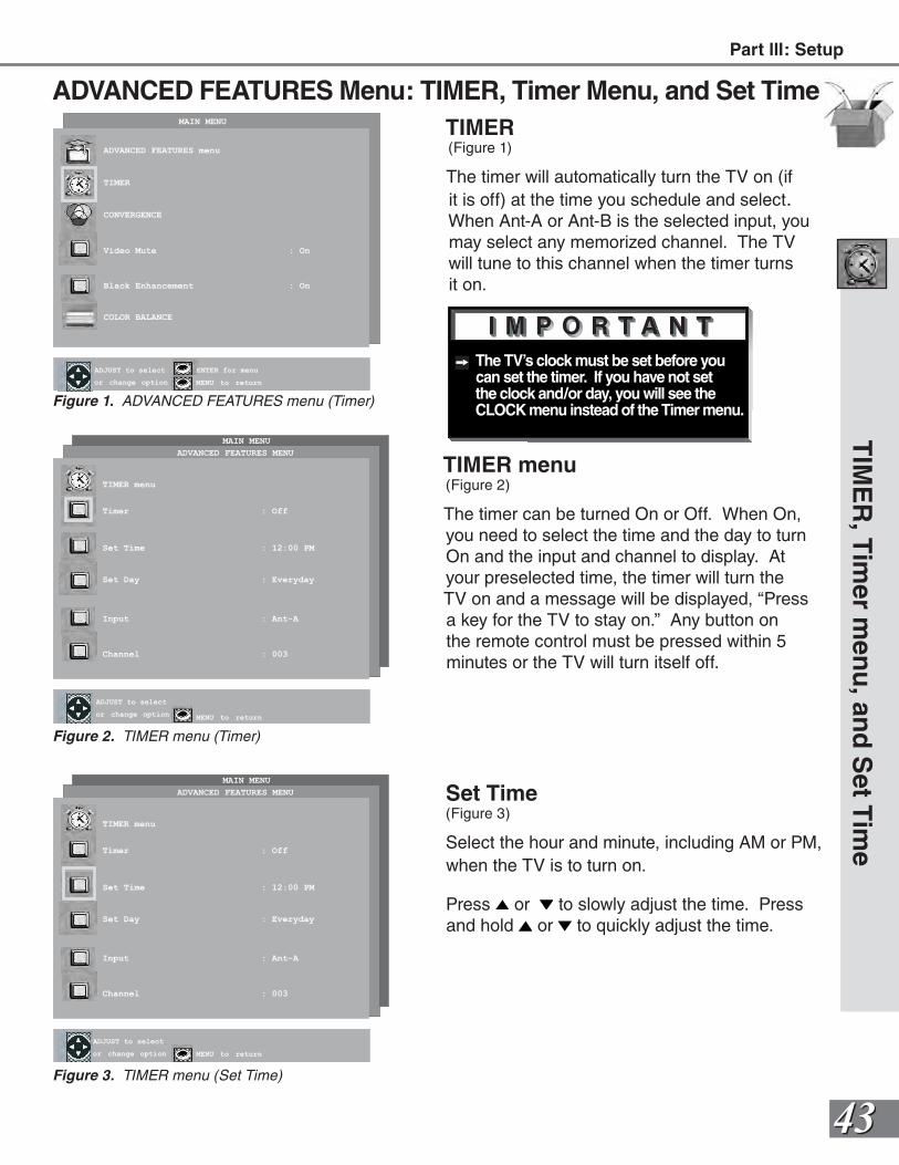
4343
The TV’s clock must be set before you can set the timer. If you have not set the clock and/or day, you will see the CLOCK menu instead of the Timer menu.
ADVANCED FEATURES Menu: TIMER, Timer Menu, and Set Time
TIMER menu(Figure 2)
The timer can be turned On or Off. When On, you need to select the time and the day to turn On and the input and channel to display. At your preselected time, the timer will turn the TV on and a message will be displayed, “Press a key for the TV to stay on.” Any button on the remote control must be pressed within 5 minutes or the TV will turn itself off.
Set Time(Figure 3)
Select the hour and minute, including AM or PM, when the TV is to turn on.
Press or to slowly adjust the time. Press and hold or to quickly adjust the time.
TIMER(Figure 1)
The timer will automatically turn the TV on (if it is off) at the time you schedule and select. When Ant-A or Ant-B is the selected input, you may select any memorized channel. The TV will tune to this channel when the timer turns it on.
TIM
ER
, Tim
er men
u, an
d S
et Tim
e
MAIN MENU
ENTER for menu or to start
MENU to return
TIMER menu
Timer : Off
Set Time : 12:00 PM
Set Day : Everyday
Input : Ant-A
Channel : 003
or change option MENU to return
ADJUST to select
ADVANCED FEATURES MENU
Figure 3. TIMER menu (Set Time)
MAIN MENU
ENTER for menu or to start
MENU to return
TIMER menu
Timer : Off
Set Time : 12:00 PM
Set Day : Everyday
Input : Ant-A
Channel : 003
or change optionMENU to return
ADJUST to select
ADVANCED FEATURES MENU
Figure 2. TIMER menu (Timer)
ENTER for menu or to start
MENU to returnor change option
ENTER for menu
MENU to return
ADJUST to select
MAIN MENU
ADVANCED FEATURES menu
TIMER
CONVERGENCE
Video Mute : On
Black Enhancement : On
COLOR BALANCE
Figure 1. ADVANCED FEATURES menu (Timer)
Figure 3. Passcode Screen
Part lll: Setup
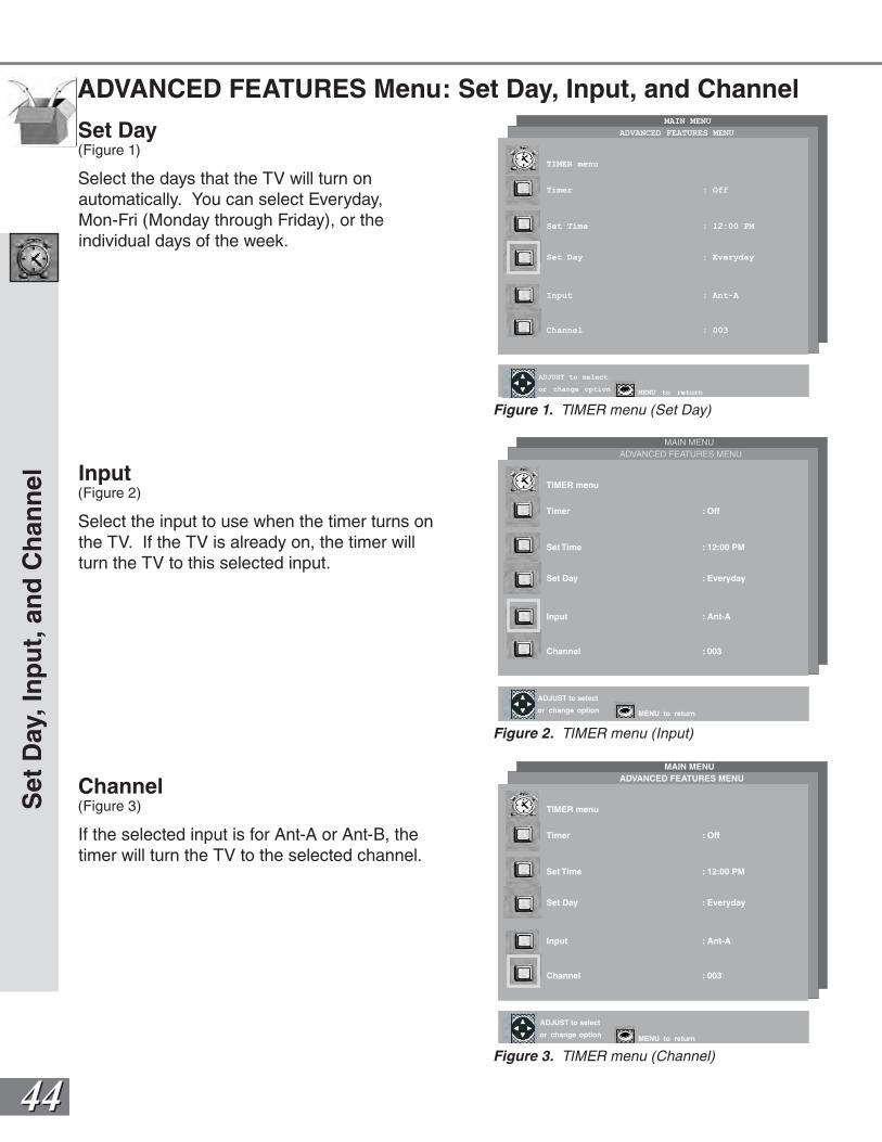
4444
ADVANCED FEATURES Menu: Set Day, Input, and Channel
Set Day(Figure 1)
Select the days that the TV will turn on automatically. You can select Everyday, Mon-Fri (Monday through Friday), or the individual days of the week.
Input(Figure 2)
Select the input to use when the timer turns on the TV. If the TV is already on, the timer will turn the TV to this selected input.
Channel(Figure 3)
If the selected input is for Ant-A or Ant-B, the timer will turn the TV to the selected channel.
Set
Day
, In
pu
t, a
nd
Ch
ann
el
MAIN MENU
ENTER for menu or to start
MENU to return
TIMER menu
Timer : Off
Set Time : 12:00 PM
Set Day : Everyday
Input : Ant-A
Channel : 003
or change option MENU to return
ADJUST to select
ADVANCED FEATURES MENU
Figure 3. TIMER menu (Channel)
MAIN MENU
ENTER for menu or to start
MENU to return
TIMER menu
Timer : Off
Set Time : 12:00 PM
Set Day : Everyday
Input : Ant-A
Channel : 003
or change option MENU to return
ADJUST to select
ADVANCED FEATURES MENU
Figure 2. TIMER menu (Input)
MAIN MENU
ENTER for menu or to start
MENU to return
TIMER menu
Timer : Off
Set Time : 12:00 PM
Set Day : Everyday
Input : Ant-A
Channel : 003
or change optionMENU to return
ADJUST to select
ADVANCED FEATURES MENU
Figure 1. TIMER menu (Set Day)
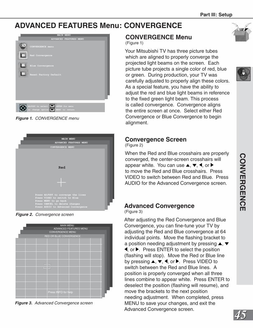
4545
ADVANCED FEATURES Menu: CONVERGENCE
CONVERGENCE Menu(Figure 1)
Your Mitsubishi TV has three picture tubes which are aligned to properly converge the projected light beams on the screen. Each picture tube projects a single color of red, blue or green. During production, your TV was carefully adjusted to properly align these colors. As a special feature, you have the ability to adjust the red and blue light beams in reference to the fixed green light beam. This process is called convergence. Convergence aligns the entire screen at once. Select either Red Convergence or Blue Convergence to begin alignment.
CO
NV
ER
GE
NC
E
MAIN MENU
ENTER for menu or to start
MENU to returnor change option
ENTER for menu
MENU to return
ADJUST to select
ADVANCED FEATURES MENU
CONVERGENCE menu
Red Convergence
Blue Convergence
Reset Factory Default
Figure 1. CONVERGENCE menu
CONVERGENCE MENU
ADVANCED FEATURES MENU
MAIN MENU
Red
Press ADJUST to converge the lines
Press VIDEO to switch to Blue
Press MENU to go back
Press CANCEL to delete changes
Press AUDIO to Advanced Convergence
Figure 2. Convergence screen
Convergence Screen(Figure 2)
When the Red and Blue crosshairs are properly converged, the center-screen crosshairs will appear white. You can use , , , or to move the Red and Blue crosshairs. Press VIDEO to switch between Red and Blue. Press AUDIO for the Advanced Convergence screen.
Advanced Convergence(Figure 3)
After adjusting the Red Convergence and Blue Convergence, you can fine-tune your TV by adjusting the Red and Blue convergence at 64 individual points. Move the flashing bracket to a position needing adjustment by pressing , , or . Press ENTER to select the position
(flashing will stop). Move the Red or Blue line by pressing , , , or . Press VIDEO to switch between the Red and Blue lines. A position is properly converged when all three lines combine to appear white. Press ENTER to deselect the position (flashing will resume), and move the brackets to the next positionneeding adjustment. When completed, press MENU to save your changes, and exit the Advanced Convergence screen.
CONVERGENCE MENUADVANCED FEATURES MENU
MAIN MENU
RED OR BLUE CONVERGENCE
Press INFO for help
Figure 3. Advanced Convergence screen
Part lll: Setup
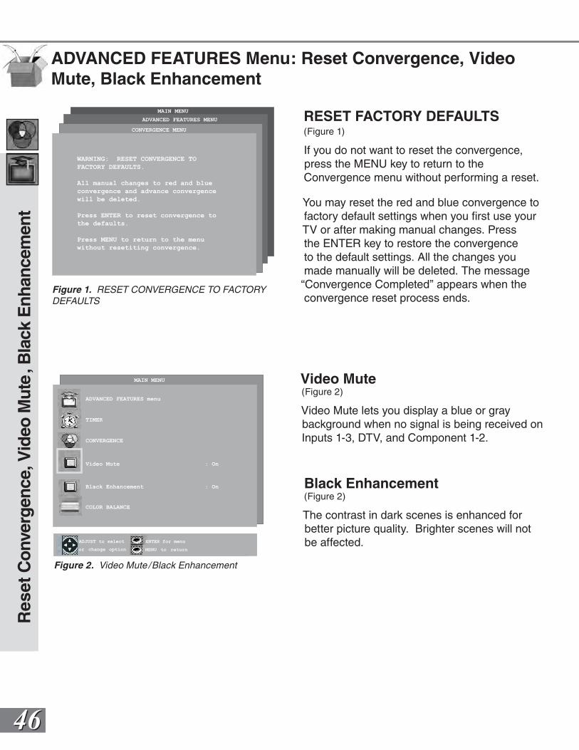
4646
Video Mute(Figure 2)
Video Mute lets you display a blue or gray background when no signal is being received on Inputs 1-3, DTV, and Component 1-2.
Res
et C
onve
rgen
ce, V
ideo
Mut
e, B
lack
Enh
ance
men
t
ENTER for menu or to start
MENU to returnor change option
ENTER for menu
MENU to return
ADJUST to select
MAIN MENU
ADVANCED FEATURES menu
TIMER
CONVERGENCE
Video Mute : On
Black Enhancement : On
COLOR BALANCE
Figure 2. Video Mute /Black Enhancement
Black Enhancement(Figure 2)
The contrast in dark scenes is enhanced for better picture quality. Brighter scenes will not be affected.
ADVANCED FEATURES Menu: Reset Convergence, Video Mute, Black Enhancement
RESET FACTORY DEFAULTS(Figure 1)
If you do not want to reset the convergence, press the MENU key to return to the Convergence menu without performing a reset.
You may reset the red and blue convergence to factory default settings when you first use your TV or after making manual changes. Press the ENTER key to restore the convergence to the default settings. All the changes you made manually will be deleted. The message “Convergence Completed” appears when the convergence reset process ends.
CONVERGENCE MENU
ADVANCED FEATURES MENU
MAIN MENU
WARNING: RESET CONVERGENCE TO
FACTORY DEFAULTS.
All manual changes to red and blue
convergence and advance convergence
will be deleted.
Press ENTER to reset convergence to
the defaults.
Press MENU to return to the menu
without resetiting convergence.
Figure 1. RESET CONVERGENCE TO FACTORY DEFAULTS
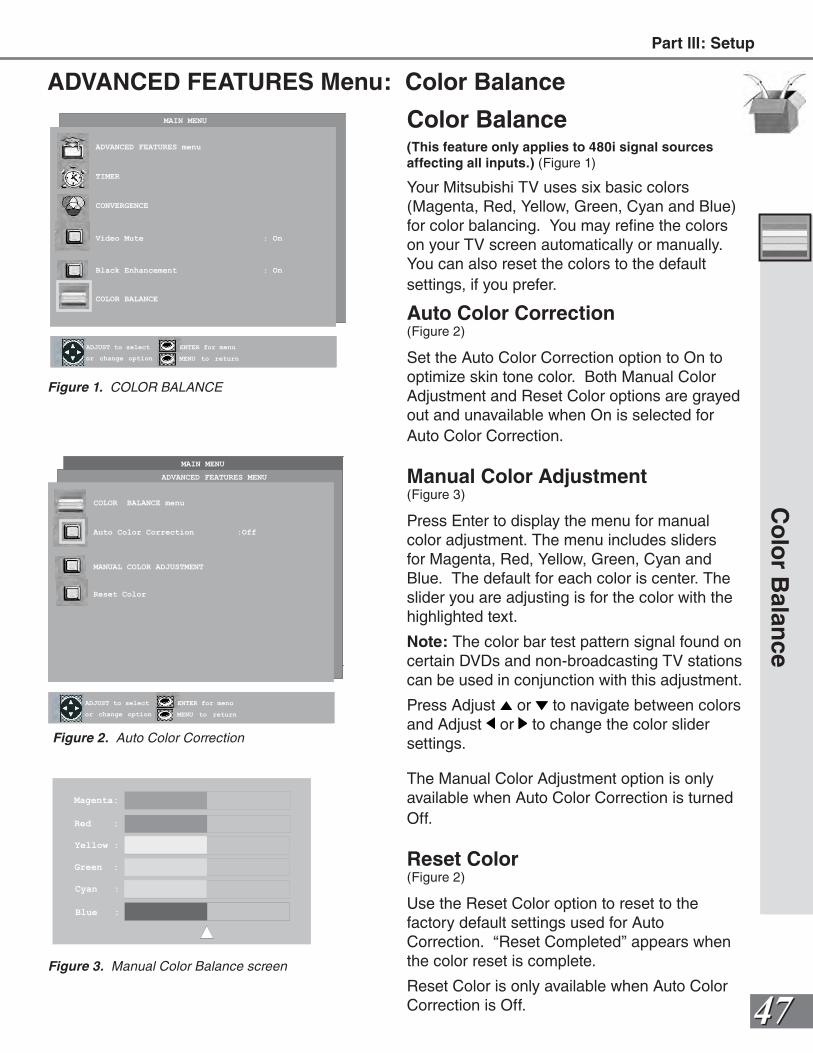
4747
ADVANCED FEATURES Menu: Color Balance
MAIN MENU
ENTER for menu or to start
MENU to returnor change option
ENTER for menu
MENU to return
ADJUST to select
ADVANCED FEATURES MENU
COLOR BALANCE menu
Auto Color Correction :Off
MANUAL COLOR ADJUSTMENT
Reset Color
Figure 2. Auto Color Correction
ENTER for menu or to start
MENU to returnor change option
ENTER for menu
MENU to return
ADJUST to select
MAIN MENU
ADVANCED FEATURES menu
TIMER
CONVERGENCE
Video Mute : On
Black Enhancement : On
COLOR BALANCE
Figure 1. COLOR BALANCE
Magenta:
Red :
Yellow :
Green :
Cyan :
Blue :
Figure 3. Manual Color Balance screen
Color Balance(This feature only applies to 480i signal sources affecting all inputs.) (Figure 1)
Your Mitsubishi TV uses six basic colors (Magenta, Red, Yellow, Green, Cyan and Blue) for color balancing. You may refine the colors on your TV screen automatically or manually. You can also reset the colors to the default settings, if you prefer.
Auto Color Correction(Figure 2)
Set the Auto Color Correction option to On to optimize skin tone color. Both Manual Color Adjustment and Reset Color options are grayed out and unavailable when On is selected for Auto Color Correction.
Manual Color Adjustment(Figure 3)
Press Enter to display the menu for manual color adjustment. The menu includes sliders for Magenta, Red, Yellow, Green, Cyan and Blue. The default for each color is center. The slider you are adjusting is for the color with the highlighted text.
Note: The color bar test pattern signal found on certain DVDs and non-broadcasting TV stations can be used in conjunction with this adjustment.
Press Adjust or to navigate between colors and Adjust or to change the color slider settings.
The Manual Color Adjustment option is only available when Auto Color Correction is turned Off.
Reset Color(Figure 2)
Use the Reset Color option to reset to the factory default settings used for Auto Correction. “Reset Completed” appears when the color reset is complete.
Reset Color is only available when Auto Color Correction is Off.
Co
lor B
alance
Part lll: Setup
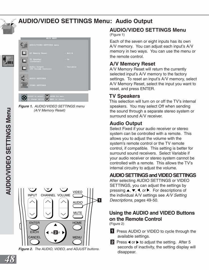
4848
AUDIO/VIDEO SETTINGS Menu: Audio Output
AUDIO/VIDEO SETTINGS Menu(Figure 1)
Each of the seven or eight inputs has its own A/V memory. You can adjust each input’s A/V memory in two ways. You can use the menu or the remote control.
A/V Memory ResetA/V Memory Reset will return the currently selected input’s A/V memory to the factory settings. To reset an input’s A/V memory, select A/V Memory Reset, select the input you want to reset, and press ENTER.
TV SpeakersThis selection will turn on or off the TV’s internal speakers. You may select Off when sending the sound through a separate stereo system or surround sound A/V receiver.
Audio OutputSelect Fixed if your audio receiver or stereo system can be controlled with a remote. This allows you to adjust the volume with the system’s remote control or the TV remote control, if compatible. This setting is better for surround sound receivers. Select Variable if your audio receiver or stereo system cannot be controlled with a remote. This allows the TV’s internal circuitry to adjust the volume.
AUDIO SETTINGS and VIDEO SETTINGSAfter selecting AUDIO SETTINGS or VIDEO SETTINGS, you can adjust the settings by pressing , , , or . For descriptions of the individual A/V settings see A/V Setting Descriptions, pages 49-50.
Using the AUDIO and VIDEO Buttons on the Remote Control(Figure 2)
1 Press AUDIO or VIDEO to cycle through the available settings.
2 Press or to adjust the setting. After 5 seconds of inactivity, the setting display will disappear.
AU
DIO
/VID
EO
SE
TTI
NG
S M
enu
ENTER for menu or to start
MENU to returnor change option
ENTER for menu
MENU to return
ADJUST to select
MAIN MENU
AUDIO/VIDEO SETTINGS menu
AV Memory Reset : Ant-A
TV Speaker : On(Internal)
Audio Output : Variable(TV Volume Control)
AUDIO SETTINGS
VIDEO SETTINGS
Figure 1. AUDIO/VIDEO SETTINGS menu (A/V Memory Reset)
POWER
INFO
PAUSEREC
FF/FWDREW/REV PLAY
STOP
3
6
9
QV
VOLUME
GUIDE
EXCH
ENTER
CANCEL MENU
V-CHIP
FORMAT
PIP CH
1
7
SQV
4
INPUT
SLEEP
VIDEO
AUDIO
MUTE
2
5
8
0
CHANNEL
ADJUST
PIP INPUT
PIP/POP
HOME
TV AUDIOCABLE/DBS DVD
VCR
Figure 2. The AUDIO, VIDEO, and ADJUST buttons.
1
2
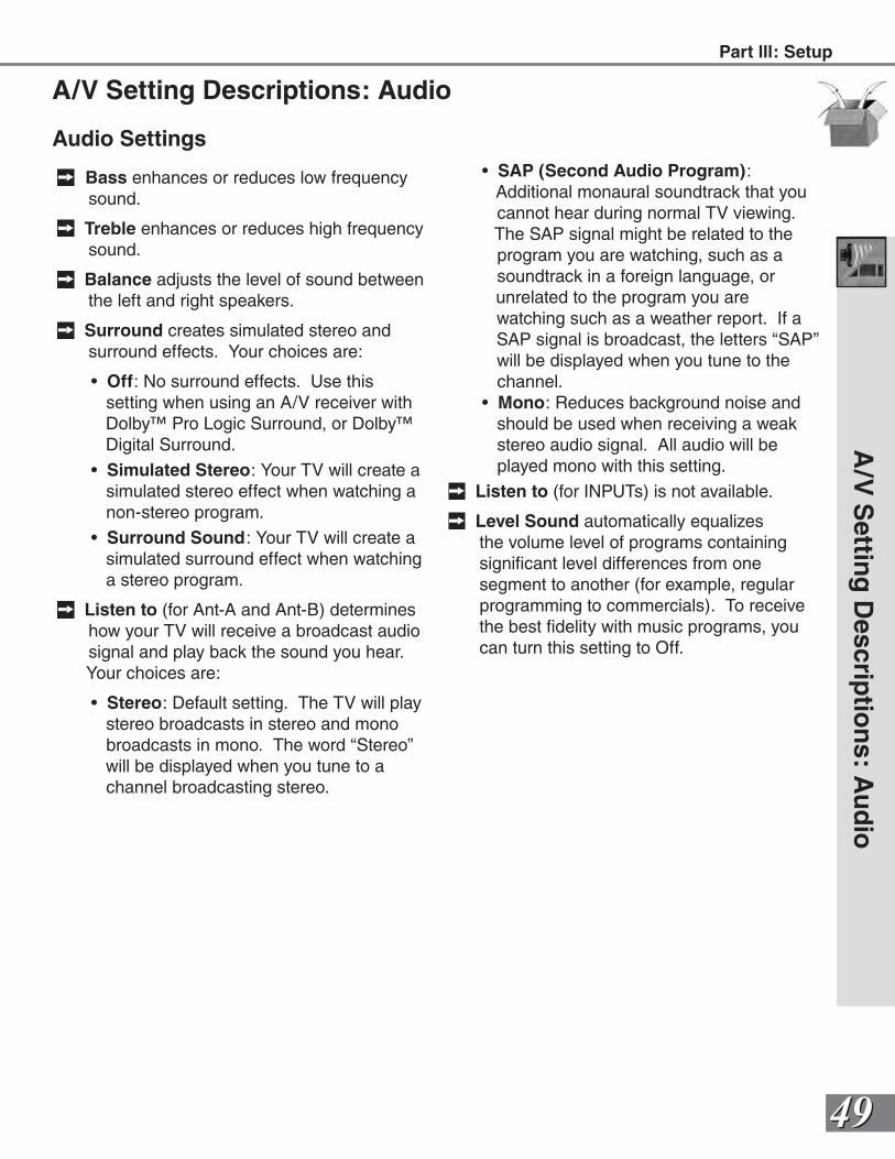
4949
Audio Settings
Bass enhances or reduces low frequency sound.
Treble enhances or reduces high frequency sound.
Balance adjusts the level of sound between the left and right speakers.
Surround creates simulated stereo and surround effects. Your choices are:
• Off: No surround effects. Use this setting when using an A/V receiver with Dolby™ Pro Logic Surround, or Dolby™ Digital Surround.
• Simulated Stereo: Your TV will create a simulated stereo effect when watching a non-stereo program.
• Surround Sound: Your TV will create a simulated surround effect when watching a stereo program.
Listen to (for Ant-A and Ant-B) determines how your TV will receive a broadcast audio signal and play back the sound you hear. Your choices are:
• Stereo: Default setting. The TV will play stereo broadcasts in stereo and mono broadcasts in mono. The word “Stereo” will be displayed when you tune to a channel broadcasting stereo.
A/V Setting Descriptions: Audio
• SAP (Second Audio Program): Additional monaural soundtrack that you cannot hear during normal TV viewing. The SAP signal might be related to the program you are watching, such as a soundtrack in a foreign language, or
unrelated to the program you are watching such as a weather report. If a SAP signal is broadcast, the letters “SAP” will be displayed when you tune to the channel.
• Mono: Reduces background noise and should be used when receiving a weak stereo audio signal. All audio will be played mono with this setting.
Listen to (for INPUTs) is not available.
Level Sound automatically equalizes the volume level of programs containing significant level differences from one segment to another (for example, regular programming to commercials). To receive the best fidelity with music programs, you can turn this setting to Off.
A/V
Settin
g D
escriptio
ns: A
ud
ioPart lll: Setup
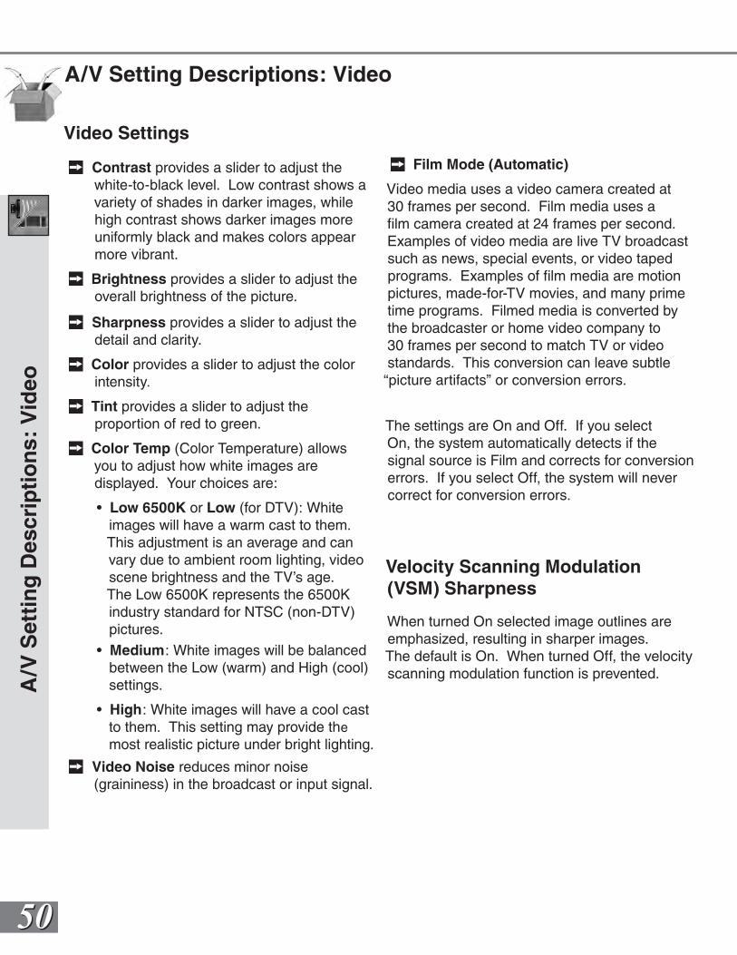
5050
A/V Setting Descriptions: Video
Video Settings
Contrast provides a slider to adjust the white-to-black level. Low contrast shows a variety of shades in darker images, while high contrast shows darker images more uniformly black and makes colors appear more vibrant.
Brightness provides a slider to adjust the overall brightness of the picture.
Sharpness provides a slider to adjust the detail and clarity.
Color provides a slider to adjust the color intensity.
Tint provides a slider to adjust the proportion of red to green.
Color Temp (Color Temperature) allows you to adjust how white images are displayed. Your choices are:
• Low 6500K or Low (for DTV): White images will have a warm cast to them. This adjustment is an average and can vary due to ambient room lighting, video scene brightness and the TV’s age. The Low 6500K represents the 6500K industry standard for NTSC (non-DTV) pictures.
• Medium: White images will be balanced between the Low (warm) and High (cool) settings.
• High: White images will have a cool cast to them. This setting may provide the most realistic picture under bright lighting.
Video Noise reduces minor noise (graininess) in the broadcast or input signal.
Film Mode (Automatic)
Video media uses a video camera created at 30 frames per second. Film media uses a film camera created at 24 frames per second. Examples of video media are live TV broadcast such as news, special events, or video taped programs. Examples of film media are motion pictures, made-for-TV movies, and many prime time programs. Filmed media is converted by the broadcaster or home video company to 30 frames per second to match TV or video standards. This conversion can leave subtle “picture artifacts” or conversion errors.
The settings are On and Off. If you select On, the system automatically detects if the signal source is Film and corrects for conversion errors. If you select Off, the system will never correct for conversion errors.
Velocity Scanning Modulation (VSM) Sharpness
When turned On selected image outlines are emphasized, resulting in sharper images.The default is On. When turned Off, the velocity scanning modulation function is prevented.
A/V
Set
tin
g D
escr
ipti
on
s: V
ideo
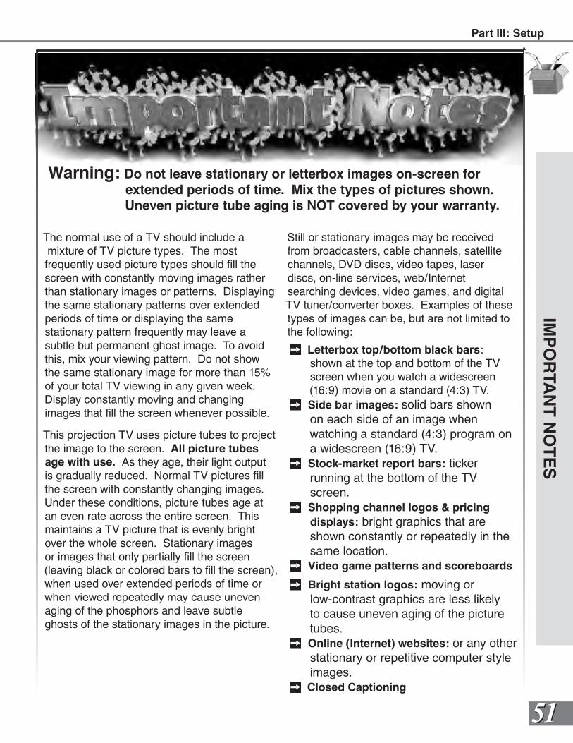
5151
IMP
OR
TAN
T N
OT
ES
Warning: Do not leave stationary or letterbox images on-screen for extended periods of time. Mix the types of pictures shown. Uneven picture tube aging is NOT covered by your warranty.
The normal use of a TV should include a mixture of TV picture types. The most frequently used picture types should fill the screen with constantly moving images rather than stationary images or patterns. Displaying the same stationary patterns over extended periods of time or displaying the same stationary pattern frequently may leave a subtle but permanent ghost image. To avoid this, mix your viewing pattern. Do not show the same stationary image for more than 15% of your total TV viewing in any given week. Display constantly moving and changingimages that fill the screen whenever possible.
This projection TV uses picture tubes to project the image to the screen. All picture tubes age with use. As they age, their light output is gradually reduced. Normal TV pictures fill the screen with constantly changing images. Under these conditions, picture tubes age at an even rate across the entire screen. This maintains a TV picture that is evenly bright over the whole screen. Stationary images or images that only partially fill the screen (leaving black or colored bars to fill the screen), when used over extended periods of time or when viewed repeatedly may cause uneven aging of the phosphors and leave subtle ghosts of the stationary images in the picture.
Still or stationary images may be received from broadcasters, cable channels, satellite channels, DVD discs, video tapes, laser discs, on-line services, web/Internet searching devices, video games, and digital TV tuner/converter boxes. Examples of these types of images can be, but are not limited to the following:
Letterbox top/bottom black bars: shown at the top and bottom of the TV screen when you watch a widescreen (16:9) movie on a standard (4:3) TV.
Side bar images: solid bars shown on each side of an image when watching a standard (4:3) program on a widescreen (16:9) TV.
Stock-market report bars: ticker running at the bottom of the TV screen.
Shopping channel logos & pricing displays: bright graphics that are shown constantly or repeatedly in the same location.
Video game patterns and scoreboards
Bright station logos: moving or low-contrast graphics are less likely to cause uneven aging of the picture tubes.
Online (Internet) websites: or any other stationary or repetitive computer style images.
Closed Captioning
Part lll: Setup

5353
OperationRemote Control Functions...... 54-65
Overview.....................................54
Care and Operation ...................55
Channel Selection .......................56
Sleep Timer ................................56
System 4 Home Theater IR Control ......................................57
Special Functions ................ 58-65
Operation of PIP and POP... 58-65
Display Formats................... 60-65
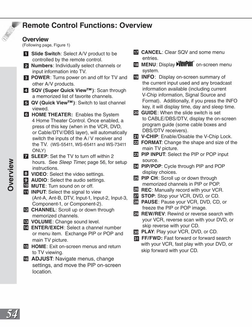
5454
Remote Control Functions: Overview
Overview(Following page, Figure 1)
1 Slide Switch: Select A/V product to be controlled by the remote control.
2 Numbers: Individually select channels or input information into TV.
3 POWER: Turns power on and off for TV and other A/V products.
4 SQV (Super Quick View™): Scan through a memorized list of favorite channels.
5 QV (Quick View™): Switch to last channel viewed.
HOME THEATER: Enables the System 4 Home Theater Control. Once enabled, a press of this key (when in the VCR, DVD, or Cable/DTV/DBS layer), will automatically switch the inputs of the A / V receiver and the TV. (WS-55411, WS-65411 and WS-73411 ONLY)
7 SLEEP: Set the TV to turn off within 2 hours. See Sleep Timer, page 56, for setup instructions.
8 VIDEO: Select the video settings.9 AUDIO: Select the audio settings.10 MUTE: Turn sound on or off.11 INPUT: Select the signal to view
(Ant-A, Ant-B, DTV, Input-1, Input-2, Input-3, Component-1, or Component-2).
12 CHANNEL: Scroll up or down through memorized channels.
13 VOLUME: Change sound level.14 ENTER/EXCH : Select a channel number
or menu item. Exchange PIP or POP and main TV picture.
15 HOME: Exit on-screen menus and return to TV viewing.
16 ADJUST: Navigate menus, change settings, and move the PIP on-screen location.
17 CANCEL: Clear SQV and some menu entries.
18 MENU: Display on-screen menu system.
19 INFO: Display on-screen summary of the current input used and any broadcast information available (including current V-Chip information, Signal Source and Format). Additionally, if you press the INFO key, it will display time, day and sleep time.
20 GUIDE: When the slide switch is set to CABLE/DBS/DTV, display the on-screen program guide (some cable boxes and DBS/DTV receivers).
21 V-CHIP: Enable/Disable the V-Chip Lock.22 FORMAT: Change the shape and size of the
main TV picture.23 PIP INPUT: Select the PIP or POP input
source.24 PIP/POP: Cycle through PIP and POP
display choices.25 PIP CH : Scroll up or down through
memorized channels in PIP or POP.26 REC: Manually record with your VCR.27 STOP: Stop your VCR, DVD, or CD.28 PAUSE: Pause your VCR, DVD, CD, or
freeze the PIP or POP image.29 REW/REV: Rewind or reverse search with
your VCR, reverse scan with your DVD, or skip reverse with your CD.
30 PLAY: Play your VCR, DVD, or CD. 31 FF/FWD: Fast forward or forward search
with your VCR, fast play with your DVD, or skip forward with your CD.
Ove
rvie
w
6
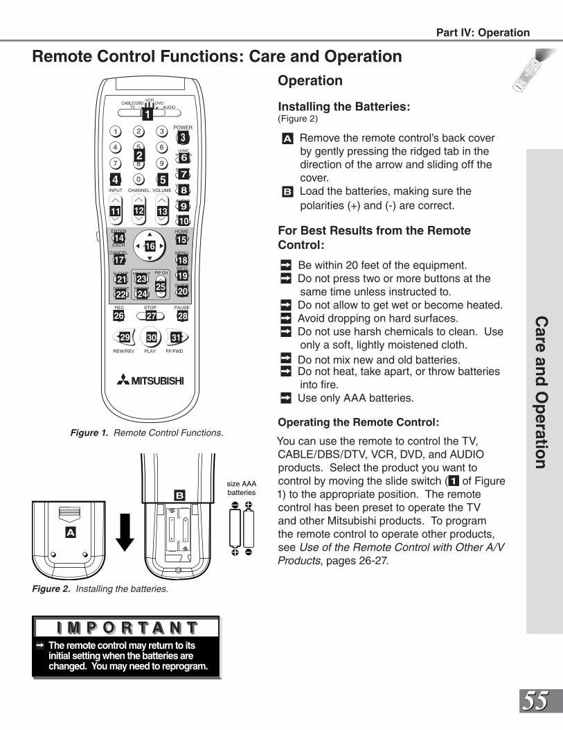
5555
The remote control may return to its initial setting when the batteries are changed. You may need to reprogram.
POWER
INFO
PAUSEREC
FF/FWDREW/REV PLAY
STOP
3
6
9
QV
VOLUME
GUIDE
EXCH
ENTER
CANCEL MENU
V-CHIP
FORMAT
PIP CH
1
7
SQV
4
INPUT
SLEEP
VIDEO
AUDIO
MUTE
2
5
8
0
CHANNEL
ADJUST
PIP INPUT
PIP/POP
HOME
TV AUDIOCABLE/DBS DVD
VCR
HOMETEATHER
Operation
Installing the Batteries:(Figure 2)
A Remove the remote control’s back cover by gently pressing the ridged tab in the direction of the arrow and sliding off the cover.
B Load the batteries, making sure the polarities (+) and (-) are correct.
For Best Results from the Remote Control:
Be within 20 feet of the equipment. Do not press two or more buttons at the
same time unless instructed to. Do not allow to get wet or become heated. Avoid dropping on hard surfaces. Do not use harsh chemicals to clean. Use
only a soft, lightly moistened cloth. Do not mix new and old batteries. Do not heat, take apart, or throw batteries
into fire. Use only AAA batteries.
Operating the Remote Control:
You can use the remote to control the TV, CABLE/DBS/DTV, VCR, DVD, and AUDIO products. Select the product you want to control by moving the slide switch ( 1 of Figure 1) to the appropriate position. The remote control has been preset to operate the TV and other Mitsubishi products. To program the remote control to operate other products, see Use of the Remote Control with Other A/V Products, pages 26-27.
Care an
d O
peratio
n
size AAAbatteries
Figure 2. Installing the batteries.
A
B
Remote Control Functions: Care and Operation
6
7
8
9
1011 12 13
14 1516
17 18
19
2021
22
23
2425
26 27 28
29 30 31
1
2
3
4 5
Figure 1. Remote Control Functions.
Part lV: Operation
5656
Remote Control Functions: Channel Selection, Sleep Timer
Channel Selection
For Non-DTV Channels:
Enter three numbers (for channel 2, press 002).
or Press the channel number and ENTER (for
channel 2, press 2, then ENTER).or
Enter the channel number and wait four seconds. The TV will change automatically.
Sleep Timer
Setting the Sleep Timer:
Press SLEEP on the remote control. A message indicating the length of time
the sleep timer is to be set appears on the TV screen.
Each press of SLEEP will increase the time displayed by 30 minutes, until the maximum value of 120 minutes is reached.
After 5 seconds of inactivity, the message will disappear.
Press SLEEP to view the remaining time before the timer turns the TV off.
Canceling the Sleep Timer:
Press SLEEP to display the on-screen message.
Press SLEEP repeatedly until OFF is displayed. After 5 seconds of inactivity, the message will disappear.
Ch
ann
el S
elec
tio
n, S
leep
Tim
er
5757
Remote Control Functions: System 4 Home Theater IR Control (WS-55411, WS-65411 and WS-73411 ONLY)
The Mitsubishi Home Theater IR System Control is a special feature that makes it easier to use your TV with a Mitsubishi digital A/V receiver. Once your equipment is properly connected and set up, your TV and Mitsubishi digital A/V receiver will change inputs together, to match high resolution pictures with the proper surround sound. See How Connections Affect the System 4 Home Theater IR Control, Pages 14-15, for installation instructions.
When you change inputs on your TV to watch different video products, your TV will send signals via the infrared emitter to your Mitsubishi digital A/V receiver and will also change inputs to hear the sound from that product. You will automatically hear the high quality digital surround sound from digital products like your DTV receiver and DVD, and high quality analog stereo or surround sound from non-digital products like your VCR.
As you change TV inputs, the A/V receiver changes its source for sound.
System
4 Ho
me T
heater IR
Co
ntro
l Part lV: Operation
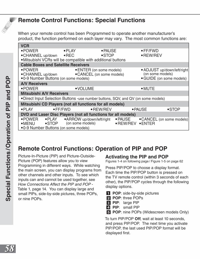
5858
VCR
Cable Boxes and Satellite Receivers
A/V Receivers
Mitsubishi CD Players (not all functions for all models)
Mitsubishi A/V Receivers
DVD and Laser Disc Players (not all functions for all models)
POWER
POWER
CHANNEL up/downENTER (on some models)
STOPPAUSE
MENU
REW/REVPLAY FF/FWD
ADJUST up/down/left/right(on some models)
VOLUME MUTE
GUIDE (on some models)CANCEL (on some models)
POWER PLAYREC STOP
PAUSE FF/FWDREW/REVCHANNEL up/down
Mitsubishi VCRs will be compatible with additional buttons
0-9 Number Buttons (on some models)
POWERSTOP
PAUSEREW/REV ENTER
PLAY ARROW up/down/left/right(on some models)
CANCEL (on some models)
0-9 Number Buttons (on some models)
Direct Input Selection Buttons -use number buttons, SQV, and QV (on some models)
Remote Control Functions: Special Functions
When your remote control has been Programmed to operate another manufacturer’s product, the function performed on each layer may vary. The most common functions are:
Remote Control Functions: Operation of PIP and POPPicture-In-Picture (PIP) and Picture-Outside- Picture (POP) features allow you to view Programming in different ways. While watching the main screen, you can display programs from other channels and other inputs. To see which inputs can and cannot be used together, see How Connections Affect the PIP and POP - Table 1, page 14. You can display large and small PIPs, side-by-side pictures, three POPs, or nine POPs.
Activating the PIP and POPFigures 1-4 on following page / Figure 1-5 on page 62
Press PIP/POP to choose a display format. Each time the PIP/POP button is pressed on the TV remote control (within 3 seconds of each other), the PIP/POP cycles through the following display options.
1 POP: side-by-side pictures2 POP: three POPs3 PIP: large PIP4 PIP: small PIP5 POP: nine POPs (Widescreen models Only)
To turn PIP/POP Off, wait at least 10 seconds, and press PIP/POP. The next time you activate PIP/POP, the last used PIP/POP format will be displayed first.
Sp
ecia
l Fu
nct
ion
s/O
per
atio
n o
f P
IP a
nd
PO
P
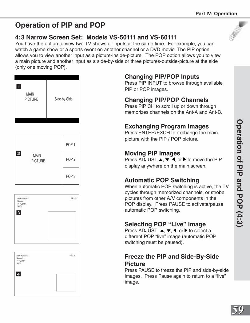
5959
Operation of PIP and POP
Changing PIP/POP InputsPress PIP INPUT to browse through available PIP or POP images.
Changing PIP/POP ChannelsPress PIP CH to scroll up or down through memorizes channels on the Ant-A and Ant-B.
Exchanging Program ImagesPress ENTER/EXCH to exchange the main picture with the PIP / POP picture.
Moving PIP ImagesPress ADJUST , , , or to move the PIP display anywhere on the main screen.
Automatic POP SwitchingWhen automatic POP switching is active, the TV cycles through memorized channels, or strobe pictures from other A/V components in the POP display. Press PAUSE to activate/pause automatic POP switching.
Selecting POP “Live” ImagePress ADJUST , , , or to select a different POP “live” image (automatic POP switching must be paused).
Freeze the PIP and Side-By-Side PicturePress PAUSE to freeze the PIP and side-by-side images. Press Pause again to return to a “live” image.
Op
eration
of P
IP an
d P
OP
(4:3)
MAIN PICTURE Side-by-Side
MAIN PICTURE
POP 1
POP 2
POP 3
1
2
3
4
PIP A 017Ant-A 002 KCBSStandardTV-PG DLSVSQV-1
PIP A 017Ant-A 002 KCBSStandardTV-PG DLSVSQV-1
4:3 Narrow Screen Set: Models VS-50111 and VS-60111You have the option to view two TV shows or inputs at the same time. For example, you can watch a game show or a sports event on another channel or a DVD movie. The PIP option allows you to view another input as a picture-inside-picture. The POP option allows you to view a main picture and another input as a side-by-side or three pictures-outside-picture at the side (only one moving POP).
Part lV: Operation
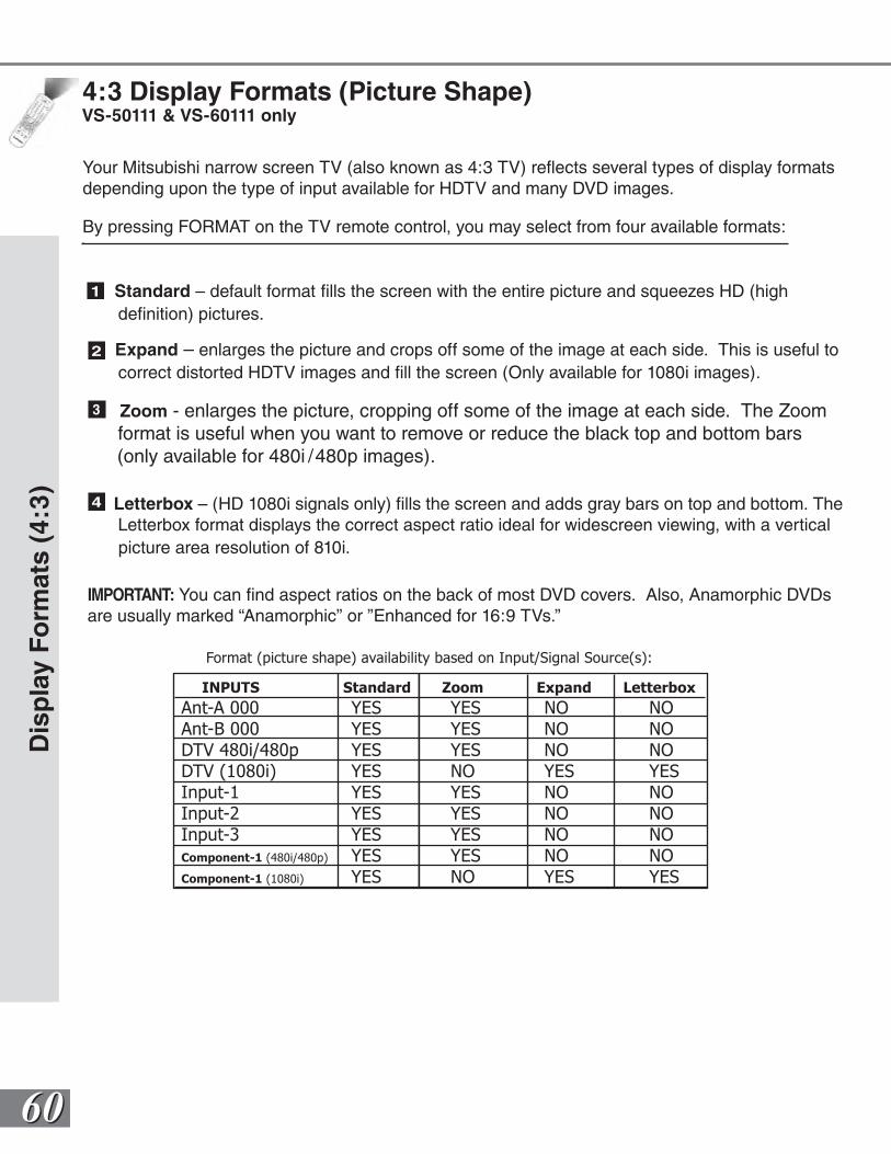
6060
4:3 Display Formats (Picture Shape)VS-50111 & VS-60111 only
1 Standard – default format fills the screen with the entire picture and squeezes HD (high definition) pictures.
2 Expand – enlarges the picture and crops off some of the image at each side. This is useful to correct distorted HDTV images and fill the screen (Only available for 1080i images).
3 Zoom - enlarges the picture, cropping off some of the image at each side. The Zoom format is useful when you want to remove or reduce the black top and bottom bars (only available for 480i /480p images).
4 Letterbox – (HD 1080i signals only) fills the screen and adds gray bars on top and bottom. The Letterbox format displays the correct aspect ratio ideal for widescreen viewing, with a vertical picture area resolution of 810i.
IMPORTANT: You can find aspect ratios on the back of most DVD covers. Also, Anamorphic DVDsare usually marked “Anamorphic” or ”Enhanced for 16:9 TVs.”
Dis
pla
y F
orm
ats
(4:3
)
Your Mitsubishi narrow screen TV (also known as 4:3 TV) reflects several types of display formats depending upon the type of input available for HDTV and many DVD images.
By pressing FORMAT on the TV remote control, you may select from four available formats:
INPUTS Standard Zoom Expand Letterbox
Ant-A 000 YES YES NO NOAnt-B 000 YES YES NO NODTV 480i/480p YES YES NO NODTV (1080i) YES NO YES YESInput-1 YES YES NO NOInput-2 YES YES NO NOInput-3 YES YES NO NOComponent-1 (480i/480p) YES YES NO NOComponent-1 (1080i) YES NO YES YES
Format (picture shape) availability based on Input/Signal Source(s):
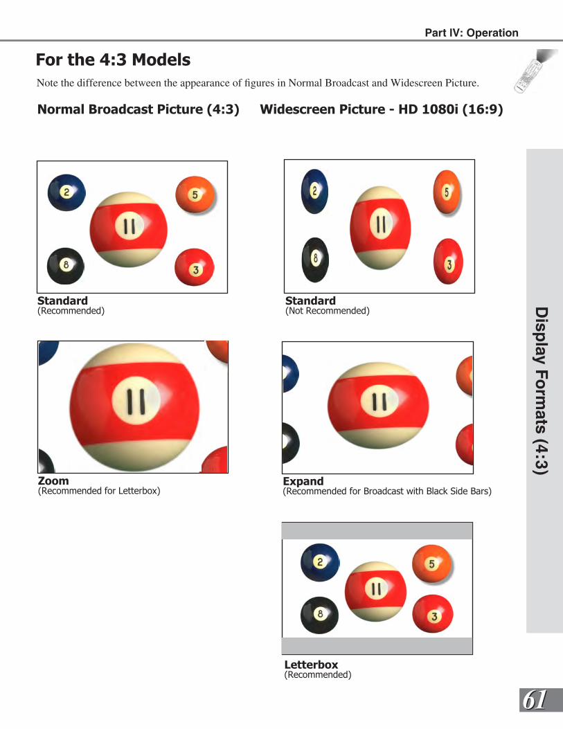
6161
Disp
lay Fo
rmats (4:3)
Part lV: Operation
For the 4:3 ModelsNote the difference between the appearance of figures in Normal Broadcast and Widescreen Picture.
Normal Broadcast Picture (4:3) Widescreen Picture - HD 1080i (16:9)
Standard(Recommended)
Standard(Not Recommended)
Zoom(Recommended for Letterbox)
Expand(Recommended for Broadcast with Black Side Bars)
Letterbox(Recommended)
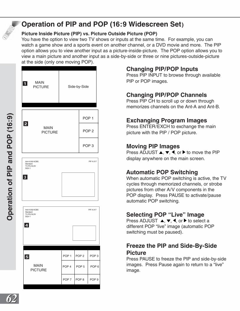
6262
Operation of PIP and POP (16:9 Widescreen Set)
Changing PIP/POP InputsPress PIP INPUT to browse through available PIP or POP images.
Changing PIP/POP ChannelsPress PIP CH to scroll up or down through memorizes channels on the Ant-A and Ant-B.
Exchanging Program ImagesPress ENTER/EXCH to exchange the main picture with the PIP / POP picture.
Moving PIP ImagesPress ADJUST , , , or to move the PIP display anywhere on the main screen.
Automatic POP SwitchingWhen automatic POP switching is active, the TV cycles through memorized channels, or strobe pictures from other A/V components in the POP display. Press PAUSE to activate/pause automatic POP switching.
Selecting POP “Live” ImagePress ADJUST , , , or to select a different POP “live” image (automatic POP switching must be paused).
Freeze the PIP and Side-By-Side PicturePress PAUSE to freeze the PIP and side-by-side images. Press Pause again to return to a “live” image.
Op
erat
ion
of
PIP
an
d P
OP
(16:
9)
MAIN PICTURE Side-by-Side
MAIN PICTURE
POP 1
POP 2
POP 3
1
2
3
4
PIP A 017Ant-A 002 KCBSStandardTV-PG DLSVSQV-1
PIP A 017Ant-A 002 KCBSStandardTV-PG DLSVSQV-1
Picture Inside Picture (PIP) vs. Picture Outside Picture (POP)You have the option to view two TV shows or inputs at the same time. For example, you can watch a game show and a sports event on another channel, or a DVD movie and more. The PIP option allows you to view another input as a picture-inside-picture. The POP option allows you to view a main picture and another input as a side-by-side or three or nine pictures-outside-picture at the side (only one moving POP).
MAINPICTURE
POP 1 POP 2 POP 3
POP 4 POP 5 POP 6
POP 7 POP 8 POP 9
5
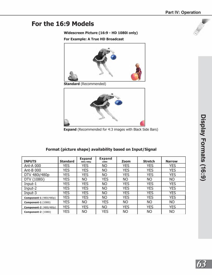
6363
INPUTS Standard 480i/480p 1080i Zoom Stretch Narrow
Ant-A 000 YES YES NO YES YES YESAnt-B 000 YES YES NO YES YES YESDTV 480i/480p YES YES NO YES YES YESDTV (1080i) YES NO YES NO NO NOInput-1 YES YES NO YES YES YESInput-2 YES YES NO YES YES YESInput-3 YES YES NO YES YES YESComponent-1 (480i/480p) YES YES NO YES YES YESComponent-1 (1080i) YES NO YES NO NO NOComponent-2 (480i/480p) YES YES NO YES YES YESComponent-2 (1080i) YES NO YES NO NO NO
Expand Expand
Disp
lay Fo
rmats (16:9)
Part lV: Operation
Expand (Recommended for 4:3 images with Black Side Bars)
Widescreen Picture (16:9 - HD 1080i only)
For Example: A True HD Broadcast
Standard (Recommended)
For the 16:9 Models
Format (picture shape) availability based on Input/Signal
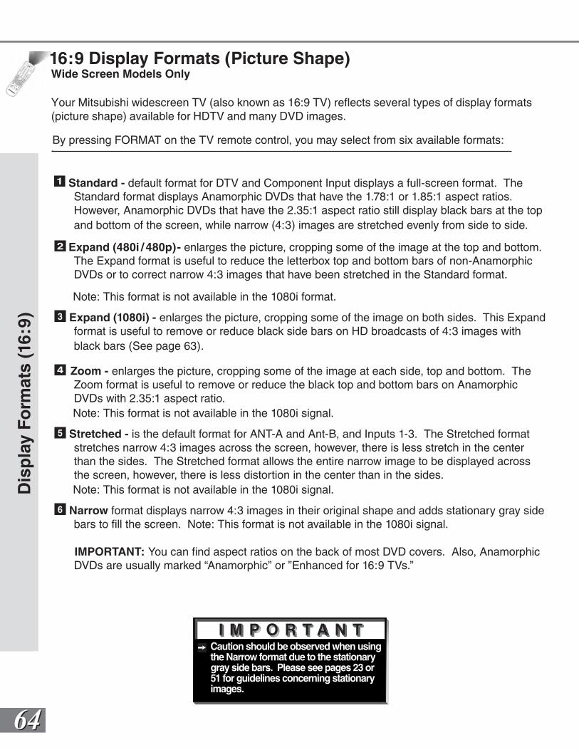
6464
Dis
pla
y F
orm
ats
(16:
9)
Caution should be observed when using the Narrow format due to the stationary gray side bars. Please see pages 23 or 51 for guidelines concerning stationary images.
Your Mitsubishi widescreen TV (also known as 16:9 TV) reflects several types of display formats (picture shape) available for HDTV and many DVD images.
By pressing FORMAT on the TV remote control, you may select from six available formats:
16:9 Display Formats (Picture Shape)Wide Screen Models Only
1 Standard - default format for DTV and Component Input displays a full-screen format. The Standard format displays Anamorphic DVDs that have the 1.78:1 or 1.85:1 aspect ratios. However, Anamorphic DVDs that have the 2.35:1 aspect ratio still display black bars at the top and bottom of the screen, while narrow (4:3) images are stretched evenly from side to side.
2 Expand (480i / 480p)- enlarges the picture, cropping some of the image at the top and bottom. The Expand format is useful to reduce the letterbox top and bottom bars of non-Anamorphic DVDs or to correct narrow 4:3 images that have been stretched in the Standard format.
Note: This format is not available in the 1080i format.
3 Expand (1080i) - enlarges the picture, cropping some of the image on both sides. This Expand format is useful to remove or reduce black side bars on HD broadcasts of 4:3 images with black bars (See page 63).
4 Zoom - enlarges the picture, cropping some of the image at each side, top and bottom. The Zoom format is useful to remove or reduce the black top and bottom bars on Anamorphic DVDs with 2.35:1 aspect ratio.
Note: This format is not available in the 1080i signal.
5 Stretched - is the default format for ANT-A and Ant-B, and Inputs 1-3. The Stretched format stretches narrow 4:3 images across the screen, however, there is less stretch in the center than the sides. The Stretched format allows the entire narrow image to be displayed across the screen, however, there is less distortion in the center than in the sides.
Note: This format is not available in the 1080i signal.
6 Narrow format displays narrow 4:3 images in their original shape and adds stationary gray side bars to fill the screen. Note: This format is not available in the 1080i signal.
IMPORTANT: You can find aspect ratios on the back of most DVD covers. Also, Anamorphic DVDs are usually marked “Anamorphic” or ”Enhanced for 16:9 TVs.”
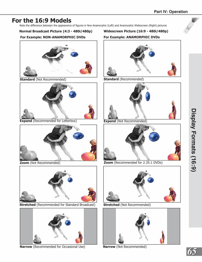
6565
Disp
lay Fo
rmats (16:9)
Part lV: Operation
For the 16:9 ModelsNote the difference between the appearance of gures in Non-Anamorphic (Left) and Anamorphic Widescreen (Right) pictures
Normal Broadcast Picture (4:3 - 480i/480p)
For Example: NON-ANAMORPHIC DVDs
Widescreen Picture (16:9 - 480i/480p)
For Example: ANAMORPHIC DVDs
Standard (Not Recommended) Standard (Recommended)
Expand (Recommended for Letterbox) Expand (Not Recommended)
Zoom (Not Recommended)
Stretched (Recommended for Standard Broadcast)
Zoom (Recommended for 2.35:1 DVDs)
Stretched (Not Recommended)
Narrow (Recommended for Occasional Use) Narrow (Not Recommended)
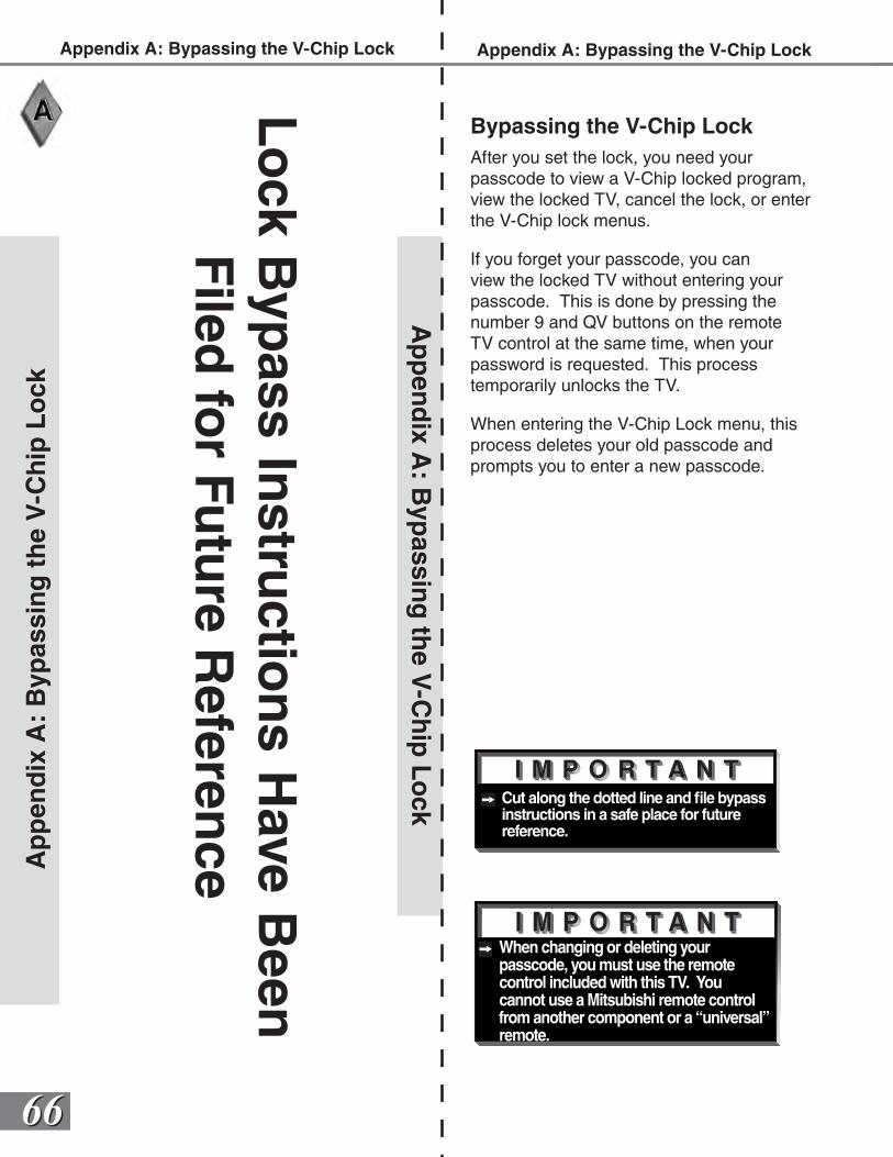
6666
When changing or deleting your passcode, you must use the remote control included with this TV. You cannot use a Mitsubishi remote control from another component or a “universal” remote.
Cut along the dotted line and file bypass instructions in a safe place for future reference.
Ap
pen
dix
A:
Byp
assi
ng
th
e V
-Ch
ip L
ock
Bypassing the V-Chip LockAfter you set the lock, you need your passcode to view a V-Chip locked program, view the locked TV, cancel the lock, or enter the V-Chip lock menus.
If you forget your passcode, you can view the locked TV without entering your passcode. This is done by pressing the number 9 and QV buttons on the remote TV control at the same time, when your password is requested. This process temporarily unlocks the TV.
When entering the V-Chip Lock menu, this process deletes your old passcode and prompts you to enter a new passcode.
Ap
pen
dix A
: Byp
assing
the V
-Ch
ip L
ock
Appendix A: Bypassing the V-Chip Lock
Lo
ck Byp
ass Instru
ction
s Have B
een
Filed
for Fu
ture R
eference
Appendix A: Bypassing the V-Chip Lock
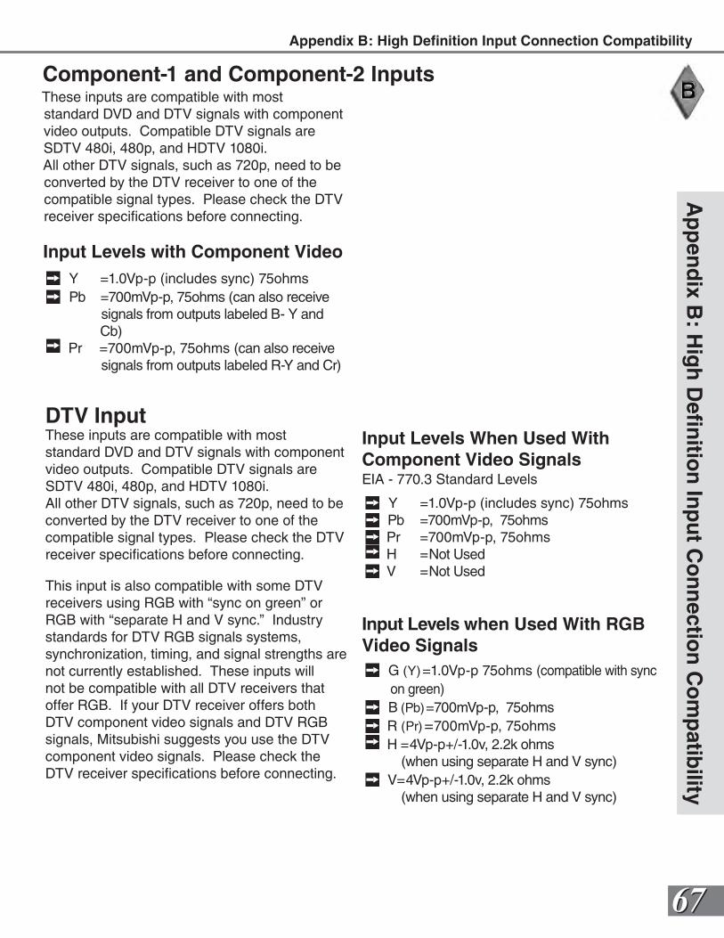
6767
Ap
pen
dix B
: Hig
h D
efin
ition
Inp
ut C
on
nectio
n C
om
patib
ility
These inputs are compatible with most standard DVD and DTV signals with component video outputs. Compatible DTV signals are SDTV 480i, 480p, and HDTV 1080i.All other DTV signals, such as 720p, need to be converted by the DTV receiver to one of the compatible signal types. Please check the DTV receiver specifications before connecting.
Component-1 and Component-2 Inputs
Input Levels with Component Video Y =1.0Vp-p (includes sync) 75ohms Pb =700mVp-p, 75ohms (can also receive
signals from outputs labeled B- Y and Cb)
Pr =700mVp-p, 75ohms (can also receive signals from outputs labeled R-Y and Cr)
DTV InputThese inputs are compatible with most standard DVD and DTV signals with component video outputs. Compatible DTV signals are SDTV 480i, 480p, and HDTV 1080i.All other DTV signals, such as 720p, need to be converted by the DTV receiver to one of the compatible signal types. Please check the DTV receiver specifications before connecting.
This input is also compatible with some DTV receivers using RGB with “sync on green” or RGB with “separate H and V sync.” Industry standards for DTV RGB signals systems, synchronization, timing, and signal strengths are not currently established. These inputs will not be compatible with all DTV receivers that offer RGB. If your DTV receiver offers both DTV component video signals and DTV RGB signals, Mitsubishi suggests you use the DTV component video signals. Please check the DTV receiver specifications before connecting.
Input Levels When Used With Component Video SignalsEIA - 770.3 Standard Levels
Y =1.0Vp-p (includes sync) 75ohms Pb =700mVp-p, 75ohms Pr =700mVp-p, 75ohms H =Not Used V =Not Used
Input Levels when Used With RGB Video Signals
G (Y)=1.0Vp-p 75ohms (compatible with sync on green)
B (Pb)=700mVp-p, 75ohms R (Pr)=700mVp-p, 75ohms H =4Vp-p+/-1.0v, 2.2k ohms
(when using separate H and V sync) V=4Vp-p+/-1.0v, 2.2k ohms
(when using separate H and V sync)
Appendix B: High Definition Input Connection Compatibility
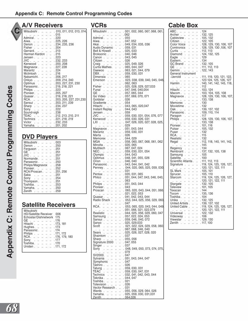
6868
Mitsubishi . .. .. .. . 010, 011, 012, 013, 014, . .. .. .. .. .. .. . 015
Admiral . .. .. .. .. . 220Aiwa. .. .. .. .. .. . 225, 226Denon . .. .. .. .. . 234, 235, 236Fisher . .. .. .. .. . 204Gerrard . .. .. .. .. . 213Harman Kardon . .. . 215Jensen . .. .. .. .. . 223JVC . .. .. .. .. .. . 232, 233Kenwood . .. .. .. . 200, 208Magnavox . .. .. .. . 227, 228Marantz . .. .. .. . 224Mclintosh . .. .. .. . 216Nakamichi . .. .. .. . 206, 217Onkyo . .. .. .. .. . 209, 214, 240Optimus . .. .. .. . 203, 227, 231, 230Panasonic . .. .. .. . 219, 218, 221Philips . .. .. .. .. . 223Pioneer . .. .. .. .. . 205, 207Quasar . .. .. .. .. . 219, 218, 221RCA. .. .. .. .. .. . 203, 205, 227, 231,230Sansui . .. .. .. .. . 203, 211, 239Sharp . .. .. .. .. . 234, 237Sony . .. .. .. .. . 222Sound-sigh . .. .. . 238TEAC . .. .. .. .. . 212, 213, 210, 211Technics . .. .. .. . 221, 218, 219Victor . .. .. .. .. . 232, 233Yamaha. .. .. .. .. . 201, 202
A/V Receivers Cable Box
Satellite Receivers
DVD PlayersMitsubishi . .. .. .. . 003Denon . .. .. .. .. . 250Ferguson . .. .. .. . 251GE . .. .. .. .. .. . 251JVC . .. .. .. .. .. . 257Normande . .. .. .. . 251Panasonic . .. .. .. . 250Philips/Magnavox . . 258Pioneer . .. .. .. .. . 252RCA/Proscan . .. .. . 251, 256Saba . .. .. .. .. . 251Sony . .. .. .. .. . 254Thompson . .. .. .. . 251Toshiba . .. .. .. .. . 253Yamaha. .. .. .. .. . 250Zenith . .. .. .. .. . 259
MitsubishiHD/Satellite Receiver 006Echostar/Dishnetwork 175GE . .. .. .. .. .. . 176Hitachi . .. .. .. .. . 173, 181Hughes. .. .. .. .. . 173Panasonic . .. .. .. . 174Philips . .. .. .. .. . 171, 172RCA. .. .. .. .. .. . 176, 179, 180Sony . .. .. .. .. . 177Toshiba . .. .. .. .. . 170Uniden . .. .. .. .. . 171, 172
ABC . .. .. .. .. .. . 124Archer . .. .. .. .. . 132, 125Cableview . .. .. .. . 105, 132Citizen . .. .. .. .. . 122, 105Color Voice . .. .. . 128, 129, 130, 106, 107Comtronics . .. .. . 128, 129, 130 ,106, 107Curtis . .. .. .. .. . 112, 113Diamond . .. .. .. . 124, 132, 125Eagle . .. .. .. .. . 129Eastern. .. .. .. .. . 134GC Brand . .. .. .. . 132, 105GE . .. .. .. .. .. . 111, 112, 113Gemini . .. .. .. .. . 122, 143General Instrument /Jerrold . .. .. .. . 111, 119, 120, 121, 122,
. .. .. .. .. .. .. . 123 124, 125, 126, 127Hamlin . .. .. .. .. . 140, 141, 142, 145, 118,
. .. .. .. .. .. .. . 112Hitachi . .. .. .. .. . 103, 124Macom . .. .. .. .. . 103, 104, 105, 108Magnavox . .. .. .. . 128, 129, 130, 106, 107,
. .. .. .. .. .. .. . 133, 138Memorex . .. .. .. . 130Movietime . .. .. .. . 132Oak . .. .. .. .. .. . 139, 137, 102Panasonic . .. .. .. . 109, 110, 114Paragon . .. .. .. . 117Philips . .. .. .. .. . 128, 129, 130, 106, 107,
. .. .. .. .. .. .. . 133, 138Pioneer . .. .. .. .. . 101, 116Pulsar . .. .. .. .. . 105, 132Puser . .. .. .. .. . 132RCA. .. .. .. .. .. . 115Realistic . .. .. .. . 132Regal . .. .. .. .. . 112, 118, 140, 141, 142,
. .. .. .. .. .. .. . 145Regency . .. .. .. . 134Rembrant . .. .. .. . 137, 132, 105, 138Samsung . .. .. .. . 105Satellite. .. .. .. .. . 100Scientific Atlanta . .. . 111, 112, 113Signature . .. .. .. . 119, 124, 125, 126, 127,
. .. .. .. .. .. .. . 120, 121, 122, 111SL Mark . .. .. .. . 105, 101Sprucer. .. .. .. .. . 105, 110Starcom . .. .. .. . 119, 124, 125, 126, 127,
. .. .. .. .. .. .. . 120, 121, 122, 111Stargate . .. .. .. . 132, 105Teleview . .. .. .. . 101, 105Texscan . .. .. .. . 144Tocom . .. .. .. .. . 135, 136Toshiba . .. .. .. .. . 104Unika . .. .. .. .. . 132, 125United Artists . .. .. . 139, 137, 102United Cable . .. .. . 119, 124, 125, 126, 127,
. .. .. .. .. .. .. . 120, 121, 122, 111Universal . .. .. .. . 122, 132Videoway . .. .. .. . 106Viewstar . .. .. .. . 129, 130Zenith . .. .. .. .. . 117, 100
Mitsubishi . .. .. .. . 001, 002, 060, 067, 068, 061, . .. .. .. .. .. .. . 062
Admiral . .. .. .. .. . 055Aiwa. .. .. .. .. .. . 047, 052Akai . .. .. .. .. .. . 049, 034, 035, 036Audio Dynamic . .. . 059, 031Bell & Howell . .. .. . 025, 033Broksonic . .. .. .. . 040, 046Canon . .. .. .. .. . 043, 045Citizen . .. .. .. .. . 026Craig . .. .. .. .. . 025, 049, 026Curtis Mathes. .. .. . 065, 044, 047Daewoo . .. .. .. . 063, 021, 044, 079DBX . .. .. .. .. .. . 059, 030, 031Dimensia . .. .. .. . 065Emerson . .. .. .. . 023, 038, 039, 040, 045, 046,
. .. .. .. .. .. .. . 062, 063Fisher . .. .. .. .. . 025, 028, 029, 027,033Funai . .. .. .. .. . 047, 046, 040,054GE . .. .. .. .. .. . 057, 065, 044Go Video . .. .. .. . 057, 069, 070, 071Goldstar . .. .. .. . 026Gradiente . .. .. .. . 054Hitachi . .. .. .. .. . 043, 065, 020,047Instant Replay . .. . 044, 043Jensen . .. .. .. .. . 059JVC . .. .. .. .. .. . 059, 030, 031, 054, 076, 077Kenwood . .. .. .. . 059, 030, 026, 031LXI . .. .. .. .. .. . 047, 026, 020, 027, 028, 025,
. .. .. .. .. .. .. . 029Magnavox . .. .. .. . 051, 043, 044Marantz . .. .. .. . 059, 030, 031Marta . .. .. .. .. . 026Memorex . .. .. .. . 044, 029MGA . .. .. .. .. . 058, 060, 067, 068, 061, 062Minolta . .. .. .. .. . 020, 065Multitech . .. .. .. . 067, 047, 024NEC. .. .. .. .. .. . 059, 030, 031, 054Olympic . .. .. .. . 044, 043Optimus . .. .. .. . 048, 041, 055, 026Orion . .. .. .. .. . 046, 040Panasonic . .. .. .. . 043, 044, 041, 042Penney . .. .. .. .. . 044, 020, 065, 025, 059, 030,
. .. .. .. .. .. .. . 031Pentax . .. .. .. .. . 020, 031, 065Philco . .. .. .. .. . 051, 044, 047, 043, 046, 040,
. .. .. .. .. .. .. . 063Philips . .. .. .. .. . 051, 043, 044Pioneer . .. .. .. .. . 043Proscan . .. .. .. . 065, 020, 043, 044, 051, 066,
. .. .. .. .. .. .. . 021, 022, 053Quasar . .. .. .. .. . 041, 042, 043, 044Radio Shack . .. .. . 053, 044, 025, 056, 029, 060,
. .. .. .. .. .. .. . 047RCA. .. .. .. .. .. . 053, 065, 020, 043, 044, 049,
. .. .. .. .. .. .. . 051, 066, 021, 022,079Realistic . .. .. .. . 044, 025, 056, 029, 060, 047Samsung . .. .. .. . 057, 022, 024, 053Sansui . .. .. .. .. . 059, 046, 040, 072Sanyo . .. .. .. .. . 025, 029,033Scott . .. .. .. .. . 021, 022, 024, 029, 058, 060,
. .. .. .. .. .. .. . 067, 068, 046, 040Sears . .. .. .. .. . 025, 026, 027, 028, 020Shaintom . .. .. .. . 037Sharp . .. .. .. .. . 055, 056Signature 2000 . .. . 047, 055Singer . .. .. .. .. . 037Sony . .. .. .. .. . 048, 049, 050, 073, 074, 075,
. .. .. .. .. .. .. . 079SV2000. .. .. .. .. . 047Sylvania . .. .. .. . 051, 043, 044, 047Symphonic . .. .. . 047Tashiro . .. .. .. .. . 026Tatung . .. .. .. .. . 059, 030, 031TEAC . .. .. .. .. . 059, 030, 047, 031Technics . .. .. .. . 032, 041, 042, 043, 044Teknika . .. .. .. .. . 044, 047Toshiba . .. .. .. .. . 021Totevision . .. .. .. . 026Vector Research . .. . 031Wards . .. .. .. .. . 055, 056, 029, 064, 026Yamaha. .. .. .. .. . 025, 059, 030, 031,031Zenith . .. .. .. .. . 064,026
VCRs
Ap
pen
dix
C:
Rem
ote
Co
ntr
ol P
rog
ram
min
g C
od
esAppendix C: Remote Control Programming Codes
6969
Ap
pen
dix D
: Clean
ing
and
Service
For further assistance, please call
(800) 332-2119 DO NOT use any kind of abrasive, liquid, or spray cleaner on the surface of the TV screen.
CleaningNormally, light dusting with a dry, non-scratching duster will keep your TV clean. If cleaning beyond this is needed, please use the following guidelines:
Top and sides of the TV:
Gently wipe down your TV with a soft, non-abrasive cloth such as cotton flannel or a clean cloth diaper, lightly moistened with water. Dry with a second dry, soft, non-abrasive cloth.
For oily dirt, add a few drops of mild liquid detergent, such as dishwashing detergent to the water used to moisten the cloth. Rinse with a second cloth moistened only with water. Dry with a third dry, soft, non-abrasive cloth.
Screen behind the Diamond Shield™:
Follow the instructions for the top and sides, however, wipe gently in an up and down motion, following the grooves in the screen.
Clean the entire screen evenly, not just sections of the screen.
Do not allow liquid to drip down the grooves of the screen as some liquid may enter the TV between the screen and the screen frame.
You may purchase Mitsubishi Screen Cleaner, part number CLEANING-VSS, by calling (800) 553-7278.
Cloth speaker grills:
Lightly brush with a soft brush.
If necessary, you can vacuum using the brush and hose attachments of your vacuum cleaner. Do not use the beater brush section on the grill cloth.
General Cleaning Warnings:
DO NOT allow liquid to enter the TV through the ventilation slots or any crevice.
DO NOT use any strong or abrasive cleaners as these can scratch the surfaces.
DO NOT use any cleaners with ammonia, bleach, alcohol, benzine, or thinners as these can dull the surfaces.
DO NOT spray liquids or cleaners directly on the TV’s surfaces.
DO NOT scrub or rub the TV harshly. Wipe it gently.
First, turn off the TV and unplug the
power cord from the power outlet.
Appendix D: Cleaning and Service
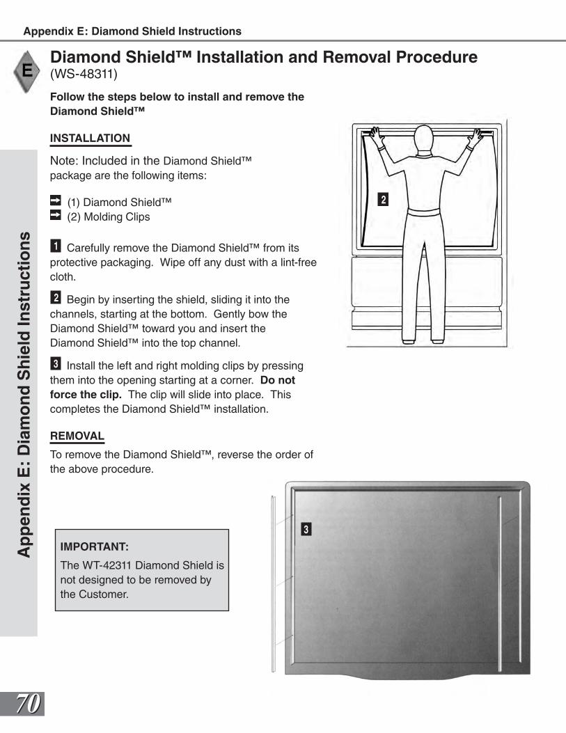
7070
Ap
pen
dix
E:
Dia
mo
nd
Sh
ield
Inst
ruct
ion
sAppendix E: Diamond Shield Instructions
Follow the steps below to install and remove the Diamond Shield™
INSTALLATION
Note: Included in the Diamond Shield™ package are the following items:
(1) Diamond Shield™ (2) Molding Clips
1 Carefully remove the Diamond Shield™ from its protective packaging. Wipe off any dust with a lint-free cloth.
2 Begin by inserting the shield, sliding it into the channels, starting at the bottom. Gently bow the Diamond Shield™ toward you and insert the Diamond Shield™ into the top channel.
3 Install the left and right molding clips by pressing them into the opening starting at a corner. Do not force the clip. The clip will slide into place. This completes the Diamond Shield™ installation.
REMOVAL
To remove the Diamond Shield™, reverse the order of the above procedure.
Diamond Shield™ Installation and Removal Procedure(WS-48311)
IMPORTANT:
The WT-42311 Diamond Shield is not designed to be removed by the Customer.
3
2
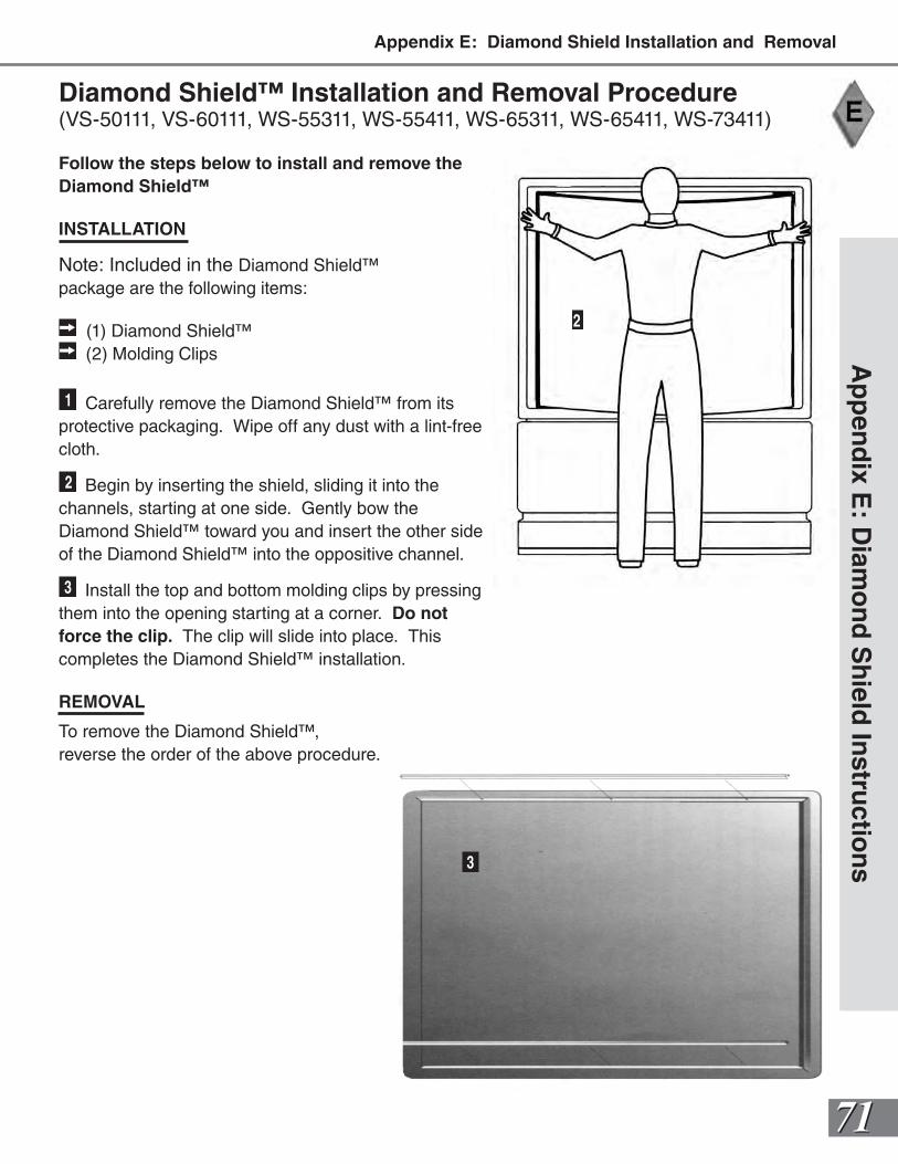
7171
Follow the steps below to install and remove the Diamond Shield™
INSTALLATION
Note: Included in the Diamond Shield™ package are the following items:
(1) Diamond Shield™ (2) Molding Clips
1 Carefully remove the Diamond Shield™ from its protective packaging. Wipe off any dust with a lint-free cloth.
2 Begin by inserting the shield, sliding it into the channels, starting at one side. Gently bow the Diamond Shield™ toward you and insert the other side of the Diamond Shield™ into the oppositive channel.
3 Install the top and bottom molding clips by pressing them into the opening starting at a corner. Do not force the clip. The clip will slide into place. This completes the Diamond Shield™ installation.
REMOVAL
To remove the Diamond Shield™, reverse the order of the above procedure.
Diamond Shield™ Installation and Removal Procedure(VS-50111, VS-60111, WS-55311, WS-55411, WS-65311, WS-65411, WS-73411)
Ap
pen
dix E
: Diam
on
d S
hield
Instru
ction
s
2
3
Appendix E: Diamond Shield Installation and Removal
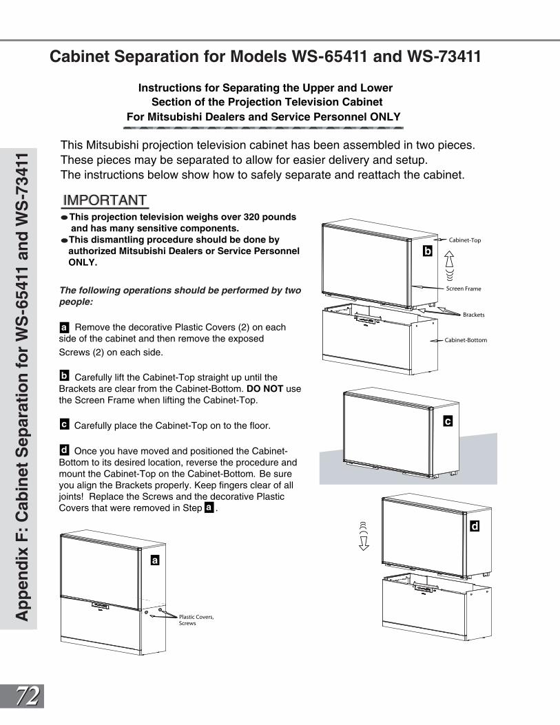
7272
The following operations should be performed by two people:
Remove the decorative Plastic Covers (2) on each side of the cabinet and then remove the exposed
Screws (2) on each side.
Carefully lift the Cabinet-Top straight up until the Brackets are clear from the Cabinet-Bottom. DO NOT use the Screen Frame when lifting the Cabinet-Top.
Carefully place the Cabinet-Top on to the floor.
Once you have moved and positioned the Cabinet-Bottom to its desired location, reverse the procedure and mount the Cabinet-Top on the Cabinet-Bottom. Be sure you align the Brackets properly. Keep fingers clear of all joints! Replace the Screws and the decorative Plastic Covers that were removed in Step .
Instructions for Separating the Upper and Lower Section of the Projection Television Cabinet
For Mitsubishi Dealers and Service Personnel ONLY
b
c
d
This projection television weighs over 320 pounds and has many sensitive components. This dismantling procedure should be done by authorized Mitsubishi Dealers or Service Personnel ONLY.
This Mitsubishi projection television cabinet has been assembled in two pieces. These pieces may be separated to allow for easier delivery and setup. The instructions below show how to safely separate and reattach the cabinet.
IMPORTANTIMPORTANT
Cabinet-Bottom
Cabinet-Top
Brackets
Screen Frame
Plastic Covers,Screws
a
b
c
d
a
a
Ap
pen
dix
F:
Cab
inet
Sep
arat
ion
fo
r W
S-6
5411
an
d W
S-7
3411
Cabinet Separation for Models WS-65411 and WS-73411
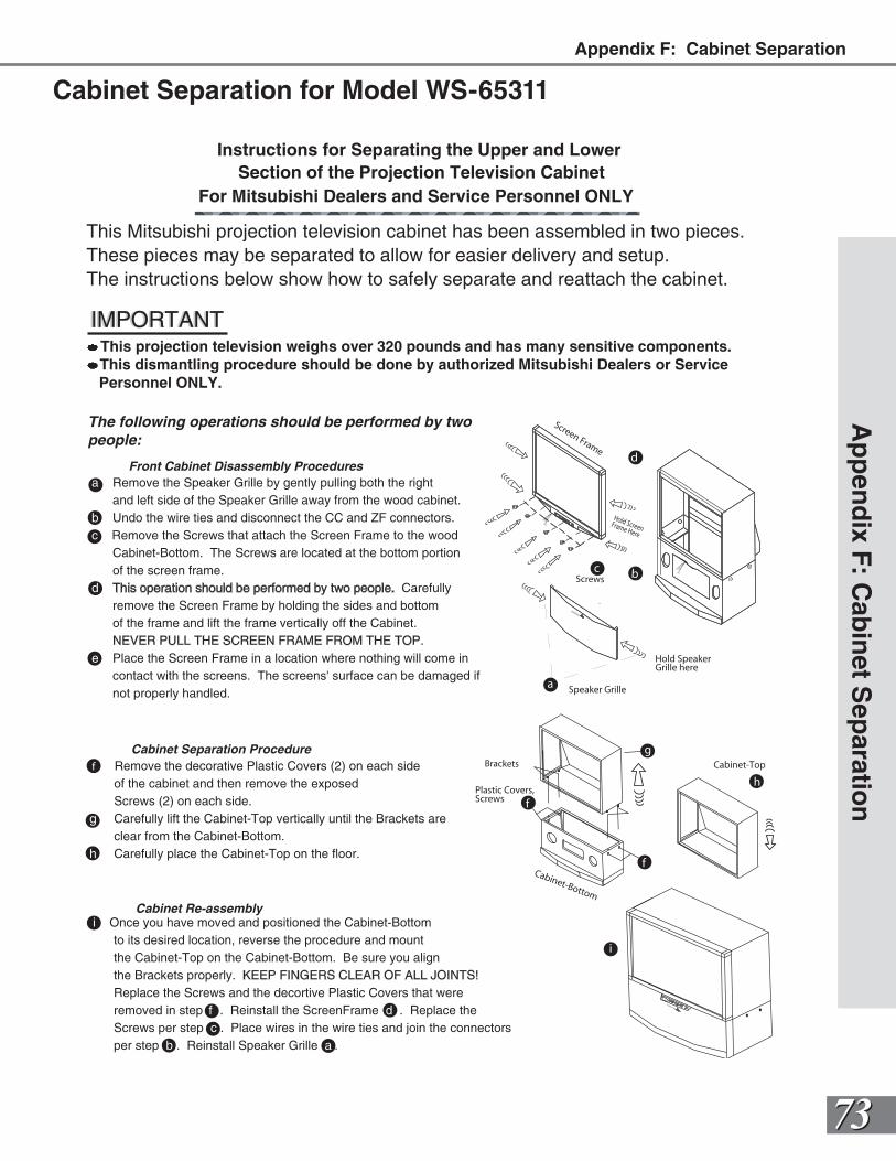
7373
h
f
i
Cabinet-Bottom
Brackets
Screen Frame
Cabinet-Top
Plastic Covers,Screws
Hold Screen Frame Here
Screws
Hold SpeakerGrille here
Speaker Grille
Front Cabinet Disassembly Proceduresa Remove the Speaker Grille by gently pulling both the right and left side of the Speaker Grille away from the wood cabinet.b Undo the wire ties and disconnect the CC and ZF connectors. c Remove the Screws that attach the Screen Frame to the wood Cabinet-Bottom. The Screws are located at the bottom portion of the screen frame.d This operation should be performed by two people. Carefully remove the Screen Frame by holding the sides and bottom of the frame and lift the frame vertically off the Cabinet. NEVER PULL THE SCREEN FRAME FROM THE TOP.e Place the Screen Frame in a location where nothing will come in contact with the screens. The screens' surface can be damaged if not properly handled.
f Remove the decorative Plastic Covers (2) on each side of the cabinet and then remove the exposed Screws (2) on each side. g Carefully lift the Cabinet-Top vertically until the Brackets are clear from the Cabinet-Bottom.h Carefully place the Cabinet-Top on the floor.
Cabinet Separation Procedure
i Once you have moved and positioned the Cabinet-Bottom to its desired location, reverse the procedure and mount the Cabinet-Top on the Cabinet-Bottom. Be sure you align the Brackets properly. KEEP FINGERS CLEAR OF ALL JOINTS! Replace the Screws and the decortive Plastic Covers that were removed in step f . Reinstall the ScreenFrame d . Replace the Screws per step c.. Place wires in the wire ties and join the connectors per step b . Reinstall Speaker Grille a .
Cabinet Re-assembly
f
Instructions for Separating the Upper and Lower Section of the Projection Television Cabinet
For Mitsubishi Dealers and Service Personnel ONLY
This projection television weighs over 320 pounds and has many sensitive components. This dismantling procedure should be done by authorized Mitsubishi Dealers or Service Personnel ONLY.
This Mitsubishi projection television cabinet has been assembled in two pieces. These pieces may be separated to allow for easier delivery and setup. The instructions below show how to safely separate and reattach the cabinet.
IMPORTANTIMPORTANT
The following operations should be performed by two people:
MITSUBISHI
g
a
c
MITSUB
ISHI
b
d
Ap
pen
dix F
: Cab
inet S
eparatio
n
Cabinet Separation for Model WS-65311
Appendix F: Cabinet Separation
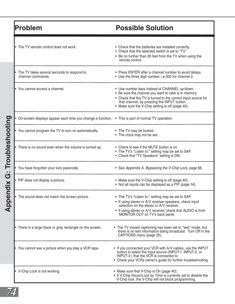
7474
Ap
pen
dix
G:
Tro
ub
lesh
oo
tin
g
Problem Possible Solution
• The TV remote control does not work. • Check that the batteries are installed correctly. • Check that the selected switch is set to “TV.” • Be no further than 20 feet from the TV when using the remote control.
• The TV takes several seconds to respond to • Press ENTER after a channel number to avoid delays. channel commands. • Use the three digit number, i.e 002 for channel 2.
• You cannot access a channel. • Use number keys instead of CHANNEL up/down. • Be sure the channel you want to view is in memory. • Check that the TV is turned to the correct input source for that channel, by pressing the INPUT button. • Make sure the V-Chip setting is off (page 40).
• On-screen displays appear each time you change a function. • This is part of normal TV operation.
• You cannot program the TV to turn on automatically. • The TV may be locked. • The clock may not be set.
• There is no sound even when the volume is turned up. • Check to see if the MUTE button is on. • The TV’s “Listen to:” setting may be set to SAP. • Check that “TV Speakers” setting is ON.
• You have forgotten your lock passcode. • See Appendix A, Bypassing the V-Chip Lock, page 66.
• PIP does not display a picture. • Make sure the V-Chip setting is off (page 40). • Not all inputs can be displayed as a PIP (page 14).
• The sound does not match the screen picture. • The TV’s “Listen to:” setting may be set to SAP. • If using stereo or A/V reveiver speakers, check input selection on the stereo or A/V receiver. • If using stereo or A/V receiver, check that AUDIO is from MONITOR OUT on TV’s back panel.
• There is a large black or gray rectangle on the screen. • The TV closed captioning has been set to “text” mode, but there is no text information being broadcast. Turn Off in the CAPTIONS menu (page 35).
• You cannot see a picture when you play a VCR tape. • If you connected your VCR with A/V cables, use the INPUT button to select the Input source (INPUT-1, INPUT-2, or INPUT-3 ) that the VCR is connected to. • Check your VCRs owner’s guide for further troubleshooting.
• V-Chip Lock is not working • Make sure that V-Chip is On (page 40). • If V-Chip Hours/Lock by Time is currently set to disable the V-Chip lock, the V-Chip will not block programming.
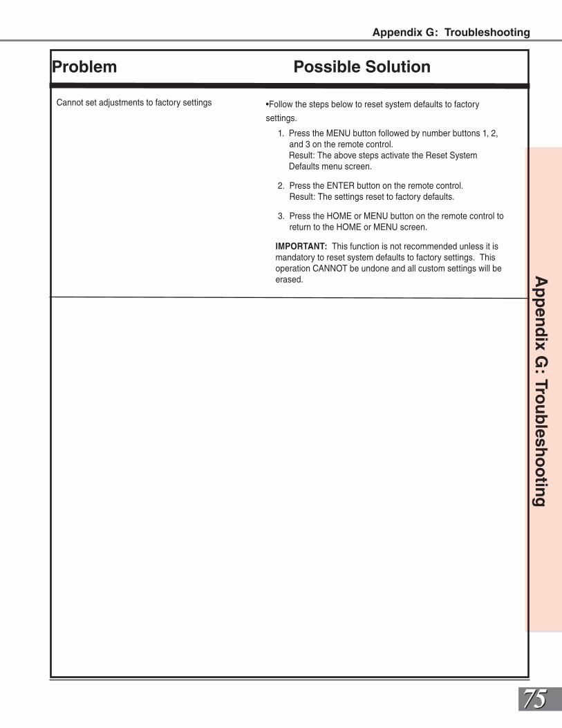
7575
Problem Possible Solution
Cannot set adjustments to factory settings •Follow the steps below to reset system defaults to factory
settings.
1. Press the MENU button followed by number buttons 1, 2, and 3 on the remote control.
Result: The above steps activate the Reset System Defaults menu screen.
2. Press the ENTER button on the remote control. Result: The settings reset to factory defaults.
3. Press the HOME or MENU button on the remote control to return to the HOME or MENU screen.
IMPORTANT: This function is not recommended unless it is mandatory to reset system defaults to factory settings. This operation CANNOT be undone and all custom settings will be erased.
Ap
pen
dix G
: Trou
blesh
oo
ting
Appendix G: Troubleshooting
7676
Ind
ex A
-Q
Aadding and deleting channels, 38Advanced Features menu, 30, 43-47adaptors (BNC to RCA), 20adjusting (convergence), 45-46alignment (convergence), 45-46antennas (connecting), 13, 16-17audio settings, 48, 49Auto Color Correction, 47
Bback panel, 13balance, 49bass, 49Black Enhancement, 46blocking (enabling V-Chip), 40-42brightness, 50bypassing (V-Chip-Lock), 66
Ccleaning, 4, 69Clock (setting), 33-34compatibility (signal), 67contrast, 50convergence, 45-46Color Balance, 47
Ddate (setting), 34daylight savings time (DST), 33dusting, 69
Eespañol, 32EXCH button on remote, 54-55
FFilm Mode (Automatic), 50formats (display), 60-65front control panel, 12
Ggames, 23, 51ghost, 23, 51
HHome Theater IR System connection, 14, 22, 57 special setups, 15 remote control functions, 26-28, 54-58
IIMPORTANT NOTES, 23, 51Important Safeguards, 4-5
Llanguage, 32letterbox, 23, 51, 60Lock by Time, 42locked, 40-42
Mmaintenance, 2, 74manual color adjustment, 47memorize channels, 31memory (channel), 38
Nnaming channels, 38naming inputs, 31
Ppasscode, 42Picture-in-Picture (PIP), 9, 14, 58-59, 62Picture-outside-Picture (POP), 9, 14, 58-59, 62
Rremote control Settings Audio, 49 Video, 50 care and operation, 55 channel selection, 56 functions, 54-65 installing batteries, 55 programming codes, 26-27, 68 replacement, 6 reset convergence, 46 reset color, 47 Sleep Timer, 56reset (A/V), 48
QQuick View™ (QV), 54
7777
Ind
ex S-W
Ssafeguards, 4-5servicing, 2, 5signal types 1080i, 14, 60-61, 63-65, 67 480i, 14, 60-61, 63-65, 67 480p (progressive DVD), 14, 60-61, 63-65, 67Sleep Timer, 56sound (adjusting), 48-49Spanish, 32Special Functions (Remote), 58SQV (Super Quick View™), 28,54stand, 4STATIONARY PICTUREWARNING, 23-51surface, 4surges, 4
Ttime (setting), 34Timer (turn TV on), 43-44Timer (Sleep), 56treble, 49Troubleshooting, 74-75TV speakers, 48
Uunpacking, 9upgradeable, 9
VV-Chip Lock, 40-42 bypassing, 66 entry to, 40 Lock by Time, 42 passcode screen, 42 ratings and categories, 41 signal information, 41 V-Chip, 40,41 V-Chip Hours, 42Velocity Scanning Modulation (VSM), 50ventilation, 4, 69Video Mute, 46Video Settings, 50
WMitsubishi Limited Warranty, 78
Index
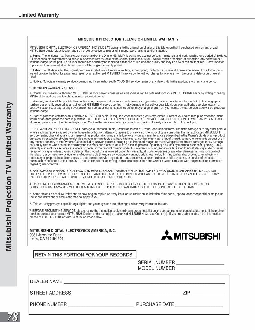
7878
Mit
sub
ish
i Pro
ject
ion
TV
Lim
ited
War
ran
tyLimited Warranty
MITSUBISHI PROJECTION TELEVISION LIMITED WARRANTY
MITSUBISHI DIGITAL ELECTRONICS AMERICA, INC. (“MDEA”) warrants to the original purchaser of this television that if purchased from an authorized MITSUBISHI Audio/Video Dealer, should it prove defective by reason of improper workmanship and/or material:
a. Parts. The lenticular (i.e. front picture) screen and/or the DiamondShield™ is warranted against defects in materials and workmanship for a period of 30 days. All other parts are warranted for a period of one year from the date of the original purchase at retail. We will repair or replace, at our option, any defective part without charge for the part. Parts used for replacement may be replaced with those of like kind and quality and may be new or remanufactured. Parts used for replacement are warranted for the remainder of the original warranty period.
b. Labor. For 30 days after the original purchase at retail, we will repair or replace, at our option, the lenticular screen if it proves defective. For all other parts, we will provide the labor for a warranty repair by an authorized MITSUBISHI service center without charge for one year from the original date or purchase at retail.
c. Notice. To obtain warranty service, you must notify an authorized MITSUBISHI service center of any defect within the applicable warranty time period.
1. TO OBTAIN WARRANTY SERVICE:
a. Contact your nearest authorized MITSUBISHI service center whose name and address can be obtained from your MITSUBISHI dealer or by writing or calling MDEA at the address and telephone number provided below.
b. Warranty service will be provided in your home or, if required, at an authorized service shop, provided that your television is located within the geographic territory customarily covered by an authorized MITSUBISHI service center. If not, you must either deliver your television to an authorized service location at your own expense, or pay for any travel and/or transportation costs the service center may charge to and from your home. Actual service labor will be provided without charge.
c. Proof of purchase date from an authorized MITSUBISHI dealer is required when requesting warranty service. Present your sales receipt or other document which establishes proof and date of purchase. THE RETURN OF THE OWNER REGISTRATION CARD IS NOT A CONDITION OF WARRANTY COVERAGE. However, please return the Owner Registration Card so that we can contact you should a question of safety arise which could affect you.
2. THIS WARRANTY DOES NOT COVER damage to Diamond Shield, Lenticular screen or Fresnel lens, screen frame, cosmetic damage or to any other product where such damage is caused by unauthorized modifi cation, alteration, repairs to or service of the product by anyone other than an authorized MITSUBISHI service center; physical abuse to or misuse of the product (including any failure to carry out any maintenance as described in the Owner’s Guide or any product damaged by excessive physical or electrical stress); any products that have had a serial number or any part thereof altered, defaced or removed; product use in any manner contrary to the Owner’s Guide (including uneven picture tube aging and imprinted images on the viewing screen); freight damage; or any damage caused by acts of God or other factors beyond the reasonable control of MDEA, such as power surge damage caused by electrical system or lightning. This warranty also excludes service calls where no defect in the product covered under this warranty is found, service calls related to unsatisfactory audio or visual reception or signal unless caused a defect in the product that is covered under this warranty, all costs, expenses or any other damages arising from product installation, or set-ups, any adjustments of user controls (including convergence, contrast, brightness, color, tint, fi ne tuning, sharpness), other adjustment necessary to prepare the unit for display or use, connection with any external audio receiver, antenna, cable or satellite systems, or service of products purchased or serviced outside the U.S.A. Please consult the operating instructions contained in the Owner’s Guide furnished with the product for information regarding user controls.
3. ANY EXPRESS WARRANTY NOT PROVIDED HEREIN, AND ANY REMEDY WHICH, BUT FOR THIS PROVISION, MIGHT ARISE BY IMPLICATION OR OPERATION OF LAW, IS HEREBY EXCLUDED AND DISCLAIMED. THE IMPLIED WARRANTIES OF MERCHANTABILITY AND FITNESS FOR ANY PARTICULAR PURPOSE ARE EXPRESSLY LIMITED TO A TERM OF ONE YEAR.
4. UNDER NO CIRCUMSTANCES SHALL MDEA BE LIABLE TO PURCHASER OR ANY OTHER PERSON FOR ANY INCIDENTAL, SPECIAL OR CONSEQUENTIAL DAMAGES, WHETHER ARISING OUT OF BREACH OF WARRANTY, BREACH OF CONTRACT, OR OTHERWISE.
5. Some states do not allow limitations on how long an implied warranty lasts, or the exclusion or limitation of incidental, special or consequential damages, so the above limitations or exclusions may not apply to you.
6. This warranty gives you specifi c legal rights, and you may also have other rights which vary from state to state.
7. BEFORE REQUESTING SERVICE, please review the instruction booklet to insure proper installation and correct customer control adjustment. If the problem persists, contact your nearest MITSUBISHI Dealer for the name(s) of authorized MITSUBISHI Service Center(s). If you are unable to obtain this information, please call 800-332-2119, or write us at the address below.
MITSUBISHI DIGITAL ELECTRONICS AMERICA, INC.9351 Jeronimo RoadIrvine, CA 92618-1904
RETAIN THIS PORTION FOR YOUR RECORDS
SERIAL NUMBER ___________________MODEL NUMBER ____________________
DEALER NAME ________________________________________________________________
STREET ADDRESS ____________________________________________ZIP _____________
PHONE NUMBER __________________________ PURCHASE DATE ___________________
© 2002 Mitsubishi Digital Electronics America, Inc. Designed and Printed in the U.S.A.871D347B10
CONSUMER RELATIONS
If you have questions regarding your television Call (800) 332-2119, or email us at
MDEAserv [email protected]
REMOTE CONTROL AND OWNER’S GUIDE
Call (800) 553-7278 to order a replacement Remote Control or Owner’s Guide.
Or visit our website at
www.Mitsubishi -TV.com