MIT EECS: 6.003 Signal Processing lecture notes (Fall 2019)
36
6.003: Signal Processing Communications Systems 5 December 2019
Transcript of MIT EECS: 6.003 Signal Processing lecture notes (Fall 2019)

6.003: Signal Processing
Communications Systems
5 December 2019
Communications Systems
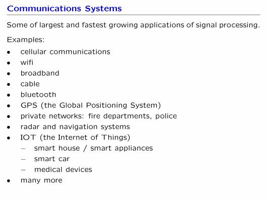
Some of largest and fastest growing applications of signal processing.
Examples:
• cellular communications
• wifi
• broadband
• cable
• bluetooth
• GPS (the Global Positioning System)
• private networks: fire departments, police
• radar and navigation systems
• IOT (the Internet of Things)
− smart house / smart appliances
− smart car
− medical devices
• many more

Telephone
Popular thirst for communications has been evident since the early
days of telephony.
mic amp telephone wire amp speaker
Patented by Alexander Graham Bell (1876) this technology flour-
ished first as a network of copper wires and later as optical fibers
(“long-distance” network) connecting virtually every household in
the US by the 1980’s.
Bell Labs became a premier research facility, developing information
theory and a host of wired and wireless communications technologies
that built on that theory, as well has hadware inovations such as the
transistor and the laser.

Cellular Communication
First demonstrated by Motorola in 1973, cellular communications
quickly revolutionized the field.
There are now more cell phones than people in the world.
sound in
sound out
cellphone
tower towercell
phonesound
in
E/M optic
fiber
E/M soundout
Much of the popularity and convenience of cellular communications
is that the communication is wireless (at least to the local tower).

Wireless Communication
Wireless signals are transmitted via electromagnetic (E/M) waves.
mic amp E/M wave amp speaker
For energy-efficient transmission and reception, the length of the
antenna should be on the order of the wavelength.
Telephone-quality speech contains frequencies from 200 to 3000 Hz.
How long should the antenna be?

Check Yourself
For energy-efficient transmission and reception, the length of
the antenna should be on the order of the wavelength.
Telephone-quality speech contains frequencies between 200 Hz
and 3000 Hz.
How long should the antenna be?
1. < 1 mm
2. ∼ cm
3. ∼m
4. ∼ km
5. > 100 km

Check Yourself
Wavelength is λ = c/f .
The lowest frequencies (200 Hz) produce the longest wavelengths
λ = c
f= 3× 10⁸ m/s
200 Hz= 1.5× 10⁶ m = 1500 km .
and highest frequencies (3000 Hz) produce the shortest wavelengths
λ = c
f= 3× 10⁸ m/s
3000 Hz= 105 m = 100 km .
The size of the antenna should be on the order of 900 miles!

Check Yourself
For energy-efficient transmission and reception, the length of
the antenna should be on the order of the wavelength.
Telephone-quality speech contains frequencies between 200 Hz
and 3000 Hz.
How long should the antenna be? 5
1. < 1 mm
2. ∼ cm
3. ∼m
4. ∼ km
5. > 100 km

Check Yourself
What frequency E/M wave is well matched to an antenna
with a length of 10 cm (about 4 inches)?
1. < 100 kHz
2. 1 MHz
3. 10 MHz
4. 100 MHz
5. > 1 GHz
Check Yourself
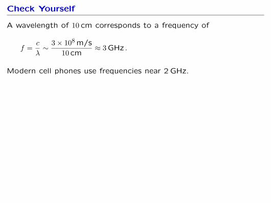
A wavelength of 10 cm corresponds to a frequency of
f = c
λ∼ 3× 10⁸ m/s
10 cm≈ 3 GHz .
Modern cell phones use frequencies near 2 GHz.
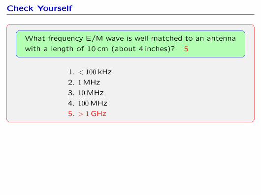
Check Yourself
What frequency E/M wave is well matched to an antenna
with a length of 10 cm (about 4 inches)? 5
1. < 100 kHz
2. 1 MHz
3. 10 MHz
4. 100 MHz
5. > 1 GHz

Wireless Communication
Speech is not well matched to the wireless medium.
Matching the message to the medium is important in all communi-
cations systems.
Example media:
• radio (E/M) waves
• cable (coaxial wires)
• fiber optics
Today we will introduce simple matching strategies based on
modulation, which underlie virtually all communication schemes.
Check Yourself
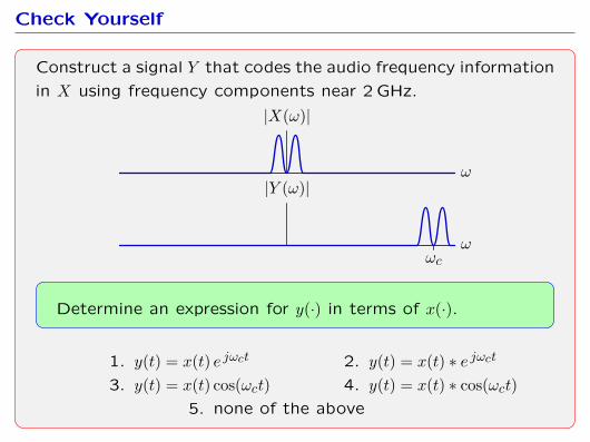
Construct a signal Y that codes the audio frequency information
in X using frequency components near 2 GHz.
ω
|X(ω)|
ωωc
|Y (ω)|
Determine an expression for y(·) in terms of x(·).
1. y(t) = x(t) e jωct 2. y(t) = x(t) ∗ e jωct
3. y(t) = x(t) cos(ωct) 4. y(t) = x(t) ∗ cos(ωct)5. none of the above

Check Yourself
Construct a signal Y that codes the audio frequency information in
X using frequency components near 2 GHz.
ω
|X(ω)|
ωωc
|Y (ω)|
Y (ω) = X(ω − ωc)
y(t) = 12π
∫Y (ω) ejωtdω = 1
2π
∫X(ω − ωc) ejωtdω
= 12π
∫X(λ) ej(λ+ωc)tdλ where λ = ω − ωc
= ejωct(
12π
∫X(λ) ejλtdλ
)= ejωctx(t)

Check Yourself
Construct a signal Y that codes the audio frequency information
in X using frequency components near 2 GHz.
ω
|X(ω)|
ωωc
|Y (ω)|
Determine an expression for Y in terms of X. 1
1. y(t) = x(t) e jωct 2. y(t) = x(t) ∗ e jωct
3. y(t) = x(t) cos(ωct) 4. y(t) = x(t) ∗ cos(ωct)5. none of the above
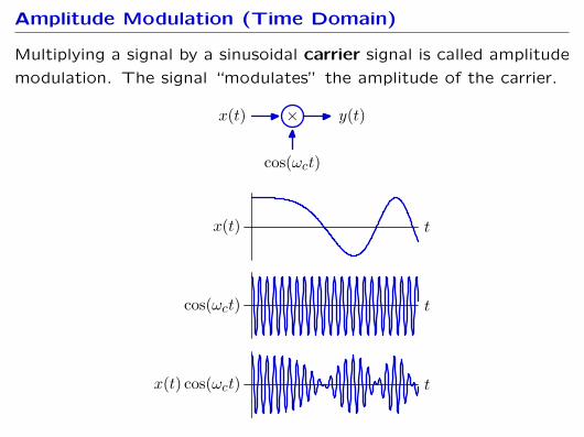
Amplitude Modulation (Time Domain)
Multiplying a signal by a sinusoidal carrier signal is called amplitude
modulation. The signal “modulates” the amplitude of the carrier.
×x(t) y(t)
cos(ωct)
tx(t) cos(ωct)
tx(t)
tcos(ωct)
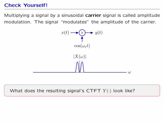
Check Yourself!
Multiplying a signal by a sinusoidal carrier signal is called amplitude
modulation. The signal “modulates” the amplitude of the carrier.
×x(t) y(t)
cos(ωct)
ω
|X(ω)|
What does the resulting signal’s CTFT Y (·) look like?

Amplitude Modulation (Frequency Domain)
Multiplying a signal by a sinusoidal carrier signal is called amplitude
modulation (AM). AM shifts the frequency components of X by ±ωc.
×x(t) y(t)
cos(ωct)
ω
|X(ω)|
ωωc−ωc
ωωc−ωc
|Y (ω)|

Amplitude Modulation
How could you recover x(t) from y(t)?
×x(t) y(t)
cos(ωct)

Synchronous Demodulation
x(·) can be recovered by multiplying by the carrier and then low-pass
filtering. This process is called synchronous demodulation.
y(t) = x(t) cos(ωct)
z(t) = y(t) cos(ωct) = x(t)× cos(ωct)× cos(ωct) = x(t)(
12
+ 12
cos(2ωct))
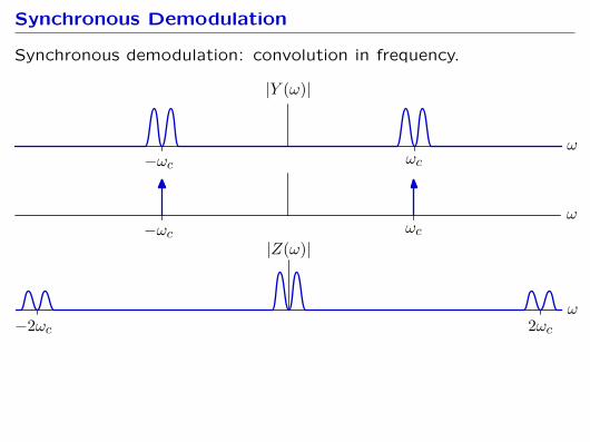
Synchronous Demodulation
Synchronous demodulation: convolution in frequency.
ωωc−ωc
|Y (ω)|
ωωc−ωc
ω2ωc−2ωc
|Z(ω)|

Synchronous Demodulation
We can recover X by low-pass filtering.
ωωc−ωc
|Y (ω)|
ωωc−ωc
ω2ωc−2ωc
|Z(ω)|2
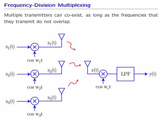
Frequency-Division Multiplexing
Multiple transmitters can co-exist, as long as the frequencies that
they transmit do not overlap.
x1(t)
x2(t)
x3(t)
z1(t)
z2(t) z(t)y(t)
z3(t)
cos w1t
cos w2t cos wct
cos w3t
LPF

Frequency-Division Multiplexing
Multiple transmitters simply sum (to first order).
x1(t)
x2(t)
x3(t)
z1(t)
z2(t) z(t)y(t)
z3(t)
cos w1t
cos w2t cos wct
cos w3t
LPF

Frequency-Division Multiplexing
Multiple transmitters can co-exist, as long as the frequencies that
they transmit do not overlap.
ω
X1(ω)
ω
X2(ω)
ω
X3(ω)

Frequency-Division Multiplexing
Multiple transmitters can co-exist, as long as the frequencies that
they transmit do not overlap.
ω
Z1(ω)
ω1
ω
Z2(ω)
ω2
ω
Z3(ω)
ω3

Frequency-Division Multiplexing
Multiple transmitters can co-exist, as long as the frequencies that
they transmit do not overlap.
ω
Z1(ω)
ω1
ω
Z2(ω)
ω2
ω
Z3(ω)
ω3
ω
Z(ω)
ω1 ω2 ω3

Broadcast Radio
“Broadcast” radio was championed by David Sarnoff, who previously
worked at Marconi Wireless Telegraphy Company (point-to-point).
• envisioned “radio music boxes”
• analogous to newspaper, but at speed of light
• receiver must be cheap (as with newsprint)
• transmitter can be expensive (as with printing press)
Sarnoff (left) and Marconi (right)

Modernity: What About Sending Digital Data?
Consider input stream x[n] of 1’s and 0’s.
Transmitter:
• Construct new stream by replicating each bit some number of
times.
• Modulate with a cosine.
• Transmit.
Receiver:
• Multiply received stream with a cosine (demodulate).
• Low-pass filter.
• Threshold result to find 1’s and 0’s, and decimate.
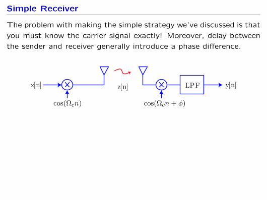
Simple Receiver
The problem with making the simple strategy we’ve discussed is that
you must know the carrier signal exactly! Moreover, delay between
the sender and receiver generally introduce a phase difference.
z[n]x[n] y[n]
cos(Ωcn) cos(Ωcn+ φ)
LPF
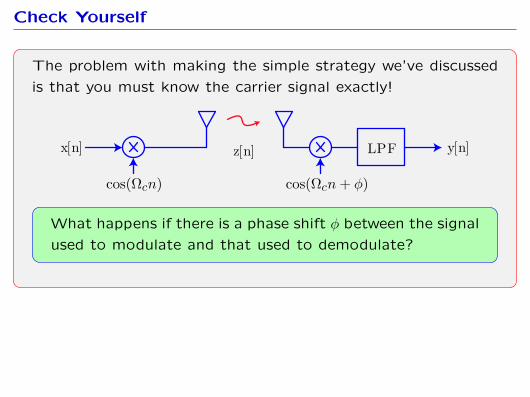
Check Yourself
The problem with making the simple strategy we’ve discussed
is that you must know the carrier signal exactly!
z[n]x[n] y[n]
cos(Ωcn) cos(Ωcn+ φ)
LPF
What happens if there is a phase shift φ between the signal
used to modulate and that used to demodulate?
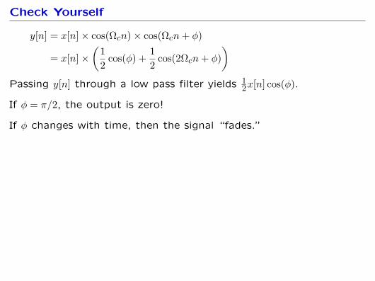
Check Yourself
y[n] = x[n]× cos(Ωcn)× cos(Ωcn+ φ)
= x[n]×(
12
cos(φ) + 12
cos(2Ωcn+ φ))
Passing y[n] through a low pass filter yields 12x[n] cos(φ).
If φ = π/2, the output is zero!
If φ changes with time, then the signal “fades.”

Fixing Phase Problems: Quadrature Demodulation
Phase errors (and channel delay) result in scaling the output ampli-
tude, where the magnitude of the scaling can’t be determined when
we design the system:
• channel delay varies on mobile devices
• phase difference between transmitter and receiver is arbitrary
One strategy to mitigate this effect is quadrature demodulation:
• Multiply by cosine to find I[n] = x[n−D]× cos(φ)• Multiply by sine to find Q[n] = x[n−D]× sin(φ)
Then, if we let w[n] = I[n] + jQ[n], we have:
|w[n]| =√I[n]2 +Q[n]2
=√
(x[n−D] cos(φ))2 + (x[n−D] sin(φ))2
= |x[n−D]|√
cos2(φ) + sin2(φ) = |x[n−D]|

Example: Sending Data via Audio
Example: audio-based communication link

Phase-shift Keying
We can do better (in terms of mitigating noise) if we encode our
bitsream as +1 and −1 instead of as 1 and 0. Called binary phase-
shift keying because the carrier changes phase when x[n] switches
from 0 to 1 (and vice versa).
However, this introduces an ambiguity between 0’s and 1’s! However,
we can fix this multiple ways:
• Send an agreed-on preamble (known bit sequence) at the start
of each message, or
• Use a different encoding (for example, a 1 corresponds to step-
ping the phase, and a 0 corresponds to keep the phase the same.

WiFi
Brief overview of WiFi.
Additional challenges! AM radio is single source→ multiple receivers.
WiFi needs to be:
• multiple source (computers) → single receiver (access point)
• single sender (access point) → single receiver (computers)
How is this accomplished (simple version)?
• Frequency division multiplexing
• Medium access control protocols for effectively sharing a channel