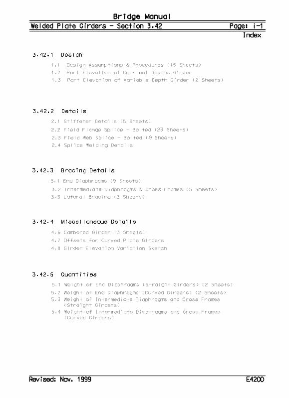
Missouri Department of Transportation Bridge Division Bridge Design … 3.42.pdf · 2003-05-29 ·...
86
Missouri Department of Transportation Bridge Division Bridge Design Manual Section 3.42 Revised 08/19/2002 Click Here for Index
Transcript of Missouri Department of Transportation Bridge Division Bridge Design … 3.42.pdf · 2003-05-29 ·...

Missouri Department of Transportation
Bridge Division
Bridge Design Manual
Section 3.42
Revised 08/19/2002
Click Here for Index
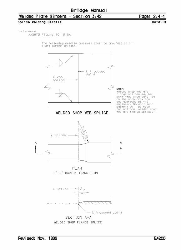
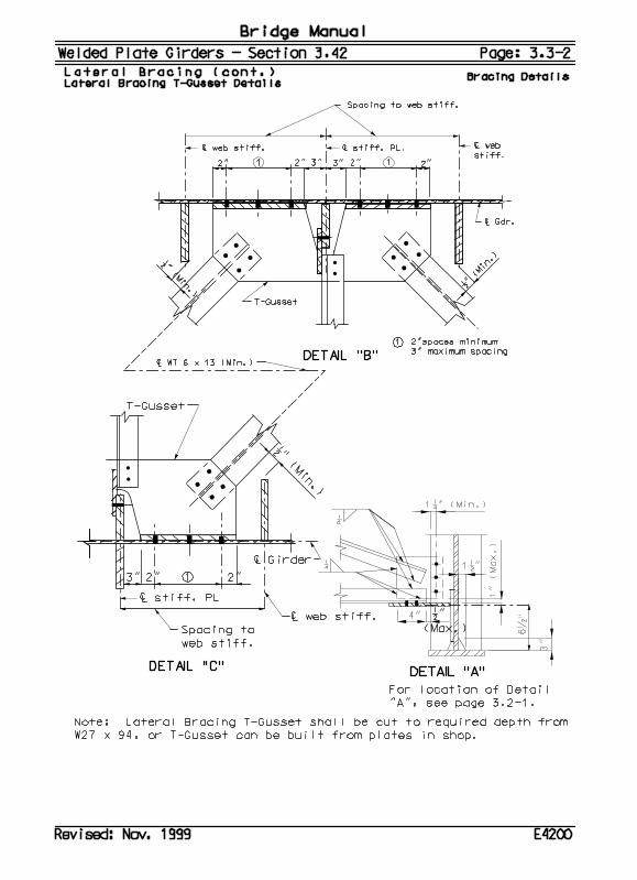
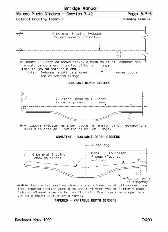
Bridge Manual Welded Plate Girders – Section 3.42 Page: 2.2-1 Field Flange Splice - Bolted Details
Revised: Jan. 2002 E4206
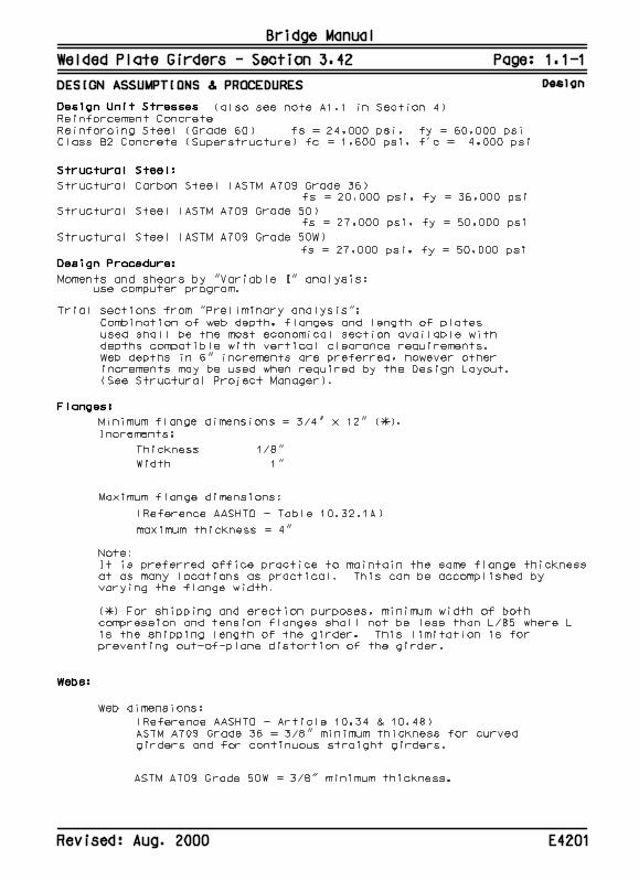
2.2 Field Flange Splice - Bolted General Splices shall be designed using the Service Load Design Method and in accordance with AASHTO Articles 10.18,10.24 and 10.32 except as noted.
Splices shall be designed to develop 100% of the flange strength by the flange splice plate strength. When the flange section or steel grade changes at a splice, the smaller flange strength shall be used to design the splice. ASTM A709 Grade 36 flange splice plates shall be used for all cases regardless of flange steel grade except when weathering steel flanges are used, splice plates shall then match the grade used in the flanges.
Minimum Yield Strength (Fy) and Minimum Tensile Strength (Fu) ASTM A709 Grade 36 Fy = 36 ksi Fu = 58 ksi ASTM A709 Grade 50 Fy = 50 ksi Fu = 65 ksi ASTM A709 Grade 50W Fy = 50 ksi Fu = 70 ksi
Allowable Steel Stresses (Ft) Allowable stresses are determined by AASHTO Table 10.32.1A. Allowable tensile stress Ft = 0.55 x Fy ASTM A709 Grade 36 Ft = 20 ksi ASTM A709 Grade 50 Ft = 27 ksi ASTM A709 Grade 50W Ft = 27 ksi
Allowable Bolt Stresses Splices shall be designed as slip critical connections with Class B surface preparation and oversized holes. Although standard holes are used in the fabrication of flange splices, designing the splices for oversize holes allows for some fabrication and erection tolerances. All splice bolts shall be 7/8" diameter ASTM A325 high strength bolts.
AASHTO Table 10.32.3C specifies Fs = 19 ksi for a class B slip-critical connection. Tables shown in this manual are based on 19 ksi that should also be used to design splices not listed in the table.
Although slip-critical connections are theoretically not subject to shear and bearing, they must be capable of resisting these stresses in the event of an overload that causes slip to occur. The allowable shear stress per bolt (Fv) for bearing is 19 ksi with the threads included and 1.25 x 19 = 23.75 ksi for threads not included.
Flange Strength The flange strength shall be determined by multiplying the allowable stress of the flange by the area of the flange. The area of the flange shall be taken as the gross area of the flange, except that if more than 15 percent of each flange area is removed, that amount
Bridge Manual Welded Plate Girders – Section 3.42 Page: 2.2-2 Field Flange Splice - Bolted Details
Revised: Jan. 2002 E4206
removed in excess of 15 percent shall be deducted from the gross area. Bolt holes are considered to be 1" diameter for the purpose of determining flange area. Splice Plate Strength The splice plate strength shall be determined by multiplying the allowable stress of the splice plates by the area of the splice plates. The area of the splice plates shall be taken as the gross area of the splice plates, except that if more than 15 percent of the splice plate area is removed, that amount in excess of 15 percent shall be deducted from the gross area.
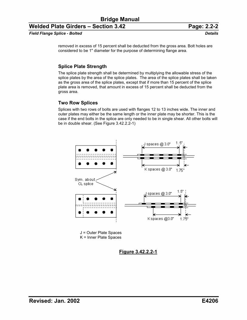
Two Row Splices Splices with two rows of bolts are used with flanges 12 to 13 inches wide. The inner and outer plates may either be the same length or the inner plate may be shorter. This is the case if the end bolts in the splice are only needed to be in single shear. All other bolts will be in double shear. (See Figure 3.42.2.2-1)
J = Outer Plate Spaces K = Inner Plate Spaces
Figure 3.42.2.2-1
Bridge Manual Welded Plate Girders – Section 3.42 Page: 2.2-3 Field Flange Splice - Bolted Details
Revised: Jan. 2002 E4206
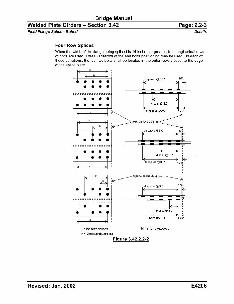
Four Row Splices When the width of the flange being spliced is 14 inches or greater, four longitudinal rows of bolts are used. Three variations of the end bolts positioning may be used. In each of these variations, the last two bolts shall be located in the outer rows closest to the edge of the splice plate.
Figure 3.42.2.2-2
Bridge Manual Welded Plate Girders – Section 3.42 Page: 2.2-4 Field Flange Splice - Bolted Details
Revised: Jan. 2002 E4206
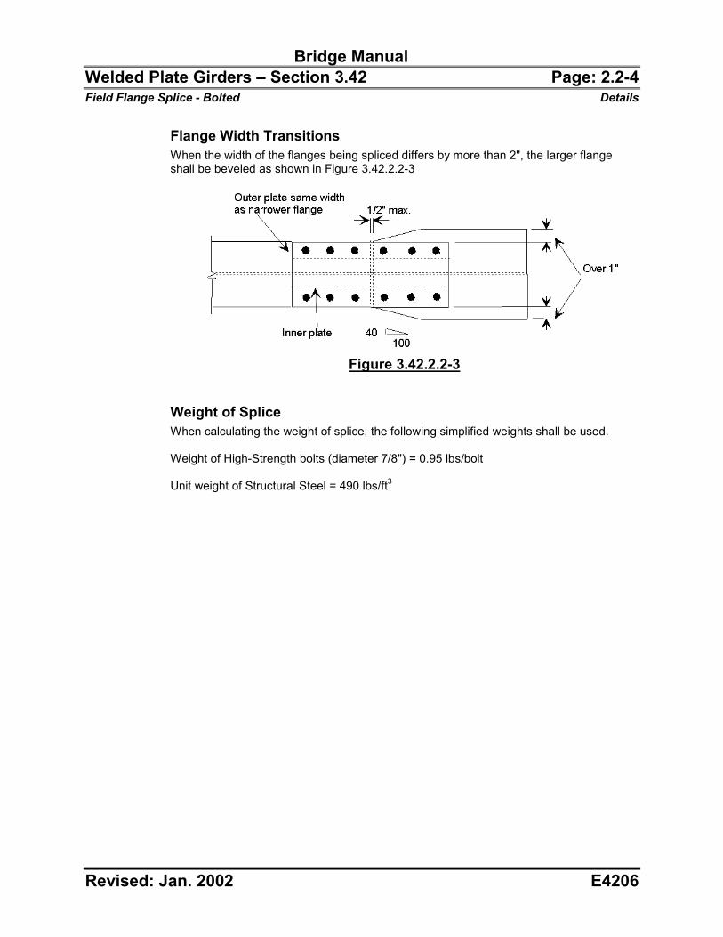
Flange Width Transitions When the width of the flanges being spliced differs by more than 2", the larger flange shall be beveled as shown in Figure 3.42.2.2-3
Figure 3.42.2.2-3
Weight of Splice When calculating the weight of splice, the following simplified weights shall be used. Weight of High-Strength bolts (diameter 7/8") = 0.95 lbs/bolt Unit weight of Structural Steel = 490 lbs/ft3
Bridge Manual Welded Plate Girders – Section 3.42 Page: 2.2-5 Field Flange Splice - Bolted Details
Revised: Jan. 2002 E4206
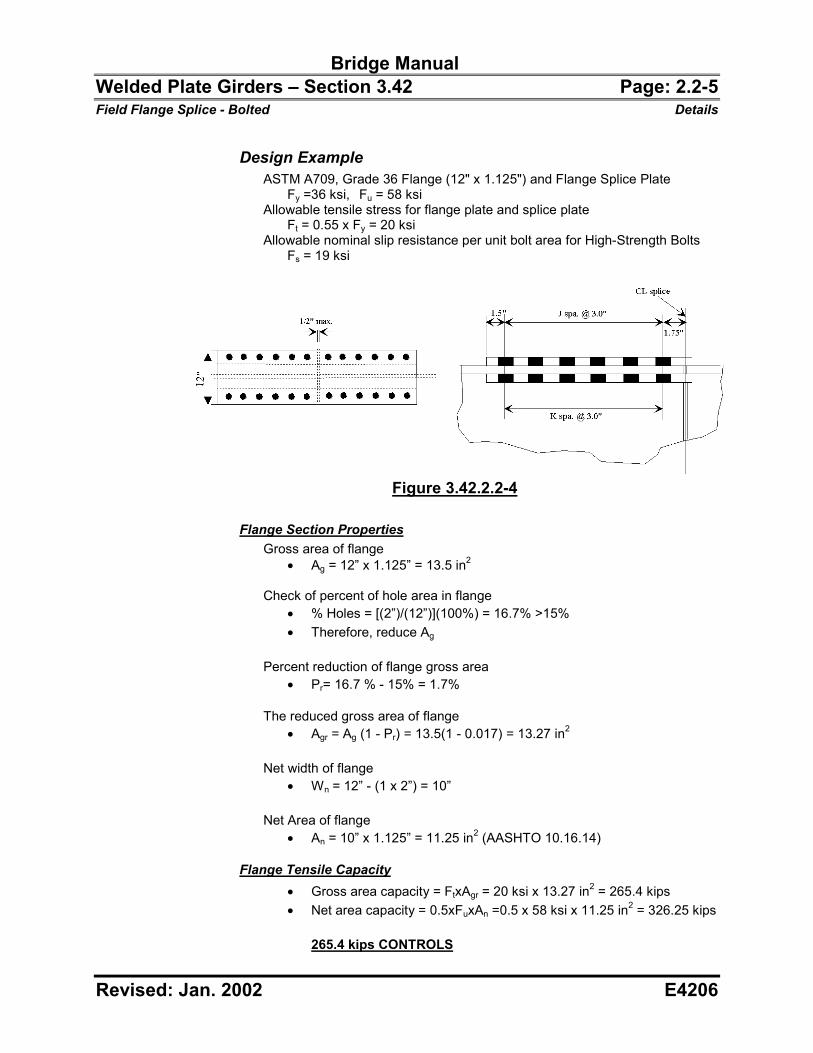
Design Example ASTM A709, Grade 36 Flange (12" x 1.125") and Flange Splice Plate Fy =36 ksi, Fu = 58 ksi Allowable tensile stress for flange plate and splice plate Ft = 0.55 x Fy = 20 ksi Allowable nominal slip resistance per unit bolt area for High-Strength Bolts Fs = 19 ksi
Figure 3.42.2.2-4
Flange Section Properties
Gross area of flange �� Ag = 12” x 1.125” = 13.5 in2
Check of percent of hole area in flange
�� % Holes = [(2”)/(12”)](100%) = 16.7% >15% �� Therefore, reduce Ag
Percent reduction of flange gross area �� Pr= 16.7 % - 15% = 1.7%
The reduced gross area of flange
�� Agr = Ag (1 - Pr) = 13.5(1 - 0.017) = 13.27 in2
Net width of flange �� Wn = 12” - (1 x 2”) = 10”
Net Area of flange �� An = 10” x 1.125” = 11.25 in2 (AASHTO 10.16.14)
Flange Tensile Capacity
�� Gross area capacity = FtxAgr = 20 ksi x 13.27 in2 = 265.4 kips �� Net area capacity = 0.5xFuxAn =0.5 x 58 ksi x 11.25 in2 = 326.25 kips
265.4 kips CONTROLS
Bridge Manual Welded Plate Girders – Section 3.42 Page: 2.2-6 Field Flange Splice - Bolted Details
Revised: Jan. 2002 E4206
Bolt Design Number of Bolts Needed Single shear allowable bolt force for slip critical and for bearing connections
�� kipsksiPall 43.11)0.19(2
"875.0 2
���
���
�� �
The number of bolts required for the splice is determined by the controlling capacity of the flange plates and the number of bolt shear sections required.
No. of shear sections required 2343.11
4.265��
Since 23 shear sections are needed for each side of the splice, we will use two rows of 6 bolts on each side. Since the bolts are in double shear a total of 24 shear sections is provided. (See Figure 3.42.2.2-4) In this situation the number of J spaces and K spaces are equal.
J = K = 5
The bolt capacity of the splice is
�� Pall x (# Bolt Shear Sections) = 11.43 kips x 24 = 274.32 kips
274.32 kips > 265.4 kips, Therefore, bolt strength is OK! Length of splice Inner and outer plate length = (2 x 5 x 3.0”) + 4(1.5”) + 0.5” = 36.5” The length of the splice needs to be checked in accordance with AASHTO Table 10.32.3B. A note states "In connections transmitting axial force whose length between extreme fasteners measured parallel to the line of force exceeds 50 inches”, the allowable stress on bolts "shall be reduced 20 percent." Length between extreme fasteners = 5 x 3.0” = 15” 15 inches < 50 inches Therefore, the assumed allowable bolt force is OK!
Splice Plate Design Gross Section of Splice Minimum required gross area of splice plate
�� Ag (Splice, Min.) = Ag (Flange) = 13.27 in2 (t)(width outer plate + width inner plates) = 13.27 (t)(12 + 2 x 5) = 13.27 t = 0.6032 Try t = 0.625”
Gross area of splice plates, Agp
�� Agp = (12” x 0.625”) + 2(5”)(0.625”) = 13.75 in2
Bridge Manual Welded Plate Girders – Section 3.42 Page: 2.2-7 Field Flange Splice - Bolted Details
Revised: Jan. 2002 E4206
Net area of splice plates, Anp �� Anp = (10” x 0.625”) + (2 x 4” x 0.625”) = 11.25 in2
Check the percentage of holes in splice plates
�� % Holes = (4x1”)/(12”+2x5”) x 100% = 18.2% >15% �� Therefore, reduce Agp
Reduction for area of holes in excess of 15%, Rh
�� Rh = 0.182 - 0.15 = 0.032 The reduced gross area of splice plates, Agr (Splice), is the gross area of the plates minus the reduction due to the area of holes over 15%.
�� Agr (Splice) = Agp (1- Rh) = 13.75x(1-0.032) = 13.31 in2 �� Agr (Flange) = Ag (1 - Pr) = 13.5x(1-0.017) = 13.27 in2
13.31 in2 > 13.27 in2, Therefore, splice plates OK!
Plate thickness = 0.625 in Outer plate width = 12 in Inner plate width = 2 @ 5 in Plate length = 36.5 in
Bearing Design Check Allowable bearing on connected material is as follows.
AASHTO Table 10.32.3B
Fp(allow) = uuc F
dFL
�5.0
Fp(allow) ksiksi 14.33"875.0
)58)("1(5.0 ��
Where: Lc = Clear distance between holes or between the holes and the end
of the splice plate in the direction of the applied force in bearing d = Diameter of bolt Bearing on flange plate steel is
�� ksibolts
kips 47.22)12)("125.1)("875.0(
4.265�
�� 22.47 ksi < 33.14 ksi Therefore,
Bearing on Flange plate is OK! Bearing on splice plate steel is
�� ksibolts
kips 22.20)12)(2)("625.0)("875.0(
4.265�
�� 20.22 ksi < 33.14 ksi Therefore,
Bearing on Splice plates is OK!
Bridge Manual Welded Plate Girders – Section 3.42 Page: 2.2-8 Field Flange Splice - Bolted Details
Revised: Jan. 2002 E4206
Weight of Splice �� Weight
= (24 bolts x 0.95 lb/bolt) + (36.5 x 0.625 x 12)(490 lb/ft3) + (36.5 x 0.625 x 5 x 2)(490 lb/ft3) = 165.1 lb/Splice (Includes outer and inner flange splice plates)
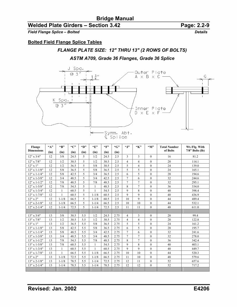
Bridge Manual Welded Plate Girders – Section 3.42 Page: 2.2-9 Field Flange Splice – Bolted Details
Revised: Jan. 2002 E4206
Bolted Field Flange Splice Tables FLANGE PLATE SIZE: 12" THRU 13" (2 ROWS OF BOLTS)
ASTM A709, Grade 36 Flanges, Grade 36 Splice
Flange
Dimensions “A”
(in)
“B”
(in)
“C”
(in)
“D”
(in)
“E”
(in)
“F”
(in)
“G”
(in)
“J” “K” “M” Total Number of Bolts
Wt./Flg. With 7/8” Bolts (lb)
12" x 3/4" 12 3/8 24.5 5 1/2 24.5 2.5 3 3 0 16 81.2 12" x 7/8" 12 1/2 30.5 5 1/2 30.5 2.5 4 4 0 20 114.1 12" x 1" 12 1/2 36.5 5 5/8 30.5 2.5 5 4 0 24 139.0 12" x 1-1/8" 12 5/8 36.5 5 5/8 36.5 2.5 5 5 0 24 165.1 12" x 1-1/4" 12 5/8 42.5 5 3/4 36.5 2.5 6 5 0 28 194.6 12" x 1-3/8" 12 3/4 48.5 5 3/4 42.5 2.5 7 6 0 32 244.6 12" x 1-1/2" 12 7/8 48.5 5 7/8 48.5 2.5 7 7 0 32 295.1 12" x 1-5/8" 12 7/8 54.5 5 1 48.5 2.5 8 7 0 36 334.0 12" x 1-3/4" 12 1 60.5 5 1 54.5 2.5 9 8 0 40 398.4 12" x 1-7/8" 12 1 60.5 5 1-1/8 60.5 2.5 9 9 0 40 436.9 12" x 2" 12 1-1/8 66.5 5 1-1/8 60.5 2.5 10 9 0 44 489.4 12" x 2-1/8" 12 1-1/8 66.5 5 1-1/4 66.5 2.5 10 10 0 44 532.1 12" x 2-1/4" 12 1-1/4 72.5 5 1-1/4 72.5 2.5 11 11 0 48 611.0 13" x 3/4" 13 3/8 30.5 5.5 1/2 24.5 2.75 4 3 0 20 99.4 13" x 7/8" 13 1/2 30.5 5.5 1/2 30.5 2.75 4 4 0 20 122.8 13" x 1" 13 1/2 36.5 5.5 5/8 36.5 2.75 5 5 0 24 161.2 13" x 1-1/8" 13 5/8 42.5 5.5 5/8 36.5 2.75 6 5 0 28 195.7 13" x 1-1/4" 13 5/8 48.5 5.5 3/4 42.5 2.75 7 6 0 32 241.6 13" x 1-3/8" 13 3/4 48.5 5.5 3/4 48.5 2.75 7 7 0 32 278.0 13" x 1-1/2" 13 7/8 54.5 5.5 7/8 48.5 2.75 8 7 0 36 342.4 13" x 1-5/8" 13 7/8 60.5 5.5 1 54.5 2.75 9 8 0 40 403.1 13" x 1-3/4" 13 1 60.5 5.5 1 60.5 2.75 9 9 0 40 449.7 13" x 1-7/8" 13 1 66.5 5.5 1-1/8 66.5 2.75 10 10 0 44 520.3 13" x 2" 13 1-1/8 72.5 5.5 1-1/8 66.5 2.75 11 10 0 48 579.6 13" x 2-1/8" 13 1-1/8 78.5 5.5 1-1/4 72.5 2.75 12 11 0 52 657.6 13" x 2-1/4" 13 1-1/4 78.5 5.5 1-1/4 78.5 2.75 12 12 0 52 717.2
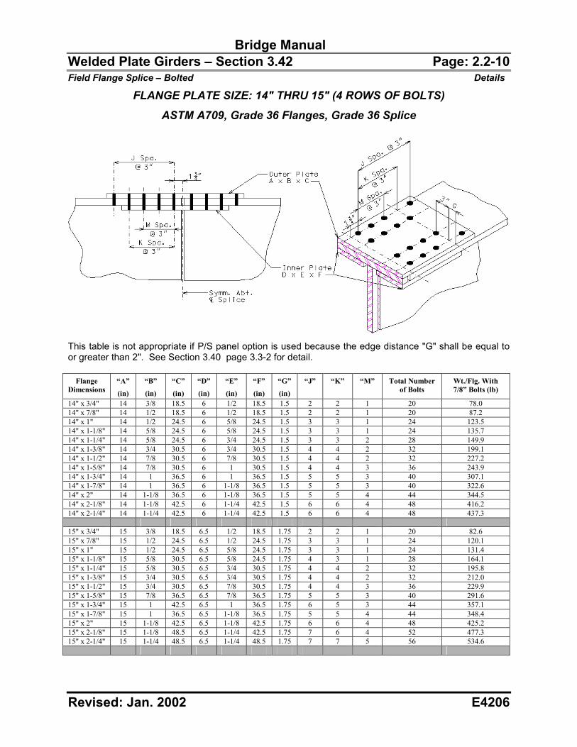
Bridge Manual Welded Plate Girders – Section 3.42 Page: 2.2-10 Field Flange Splice – Bolted Details
Revised: Jan. 2002 E4206
FLANGE PLATE SIZE: 14" THRU 15" (4 ROWS OF BOLTS) ASTM A709, Grade 36 Flanges, Grade 36 Splice
This table is not appropriate if P/S panel option is used because the edge distance "G" shall be equal to or greater than 2". See Section 3.40 page 3.3-2 for detail.
Flange Dimensions
“A”
(in)
“B”
(in)
“C”
(in)
“D”
(in)
“E”
(in)
“F”
(in)
“G”
(in)
“J” “K” “M” Total Number of Bolts
Wt./Flg. With 7/8” Bolts (lb)
14" x 3/4" 14 3/8 18.5 6 1/2 18.5 1.5 2 2 1 20 78.0 14" x 7/8" 14 1/2 18.5 6 1/2 18.5 1.5 2 2 1 20 87.2 14" x 1" 14 1/2 24.5 6 5/8 24.5 1.5 3 3 1 24 123.5 14" x 1-1/8" 14 5/8 24.5 6 5/8 24.5 1.5 3 3 1 24 135.7 14" x 1-1/4" 14 5/8 24.5 6 3/4 24.5 1.5 3 3 2 28 149.9 14" x 1-3/8" 14 3/4 30.5 6 3/4 30.5 1.5 4 4 2 32 199.1 14" x 1-1/2" 14 7/8 30.5 6 7/8 30.5 1.5 4 4 2 32 227.2 14" x 1-5/8" 14 7/8 30.5 6 1 30.5 1.5 4 4 3 36 243.9 14" x 1-3/4" 14 1 36.5 6 1 36.5 1.5 5 5 3 40 307.1 14" x 1-7/8" 14 1 36.5 6 1-1/8 36.5 1.5 5 5 3 40 322.6 14" x 2" 14 1-1/8 36.5 6 1-1/8 36.5 1.5 5 5 4 44 344.5 14" x 2-1/8" 14 1-1/8 42.5 6 1-1/4 42.5 1.5 6 6 4 48 416.2 14" x 2-1/4" 14 1-1/4 42.5 6 1-1/4 42.5 1.5 6 6 4 48 437.3 15" x 3/4" 15 3/8 18.5 6.5 1/2 18.5 1.75 2 2 1 20 82.6 15" x 7/8" 15 1/2 24.5 6.5 1/2 24.5 1.75 3 3 1 24 120.1 15" x 1" 15 1/2 24.5 6.5 5/8 24.5 1.75 3 3 1 24 131.4 15" x 1-1/8" 15 5/8 30.5 6.5 5/8 24.5 1.75 4 3 1 28 164.1 15" x 1-1/4" 15 5/8 30.5 6.5 3/4 30.5 1.75 4 4 2 32 195.8 15" x 1-3/8" 15 3/4 30.5 6.5 3/4 30.5 1.75 4 4 2 32 212.0 15" x 1-1/2" 15 3/4 30.5 6.5 7/8 30.5 1.75 4 4 3 36 229.9 15" x 1-5/8" 15 7/8 36.5 6.5 7/8 36.5 1.75 5 5 3 40 291.6 15" x 1-3/4" 15 1 42.5 6.5 1 36.5 1.75 6 5 3 44 357.1 15" x 1-7/8" 15 1 36.5 6.5 1-1/8 36.5 1.75 5 5 4 44 348.4 15" x 2" 15 1-1/8 42.5 6.5 1-1/8 42.5 1.75 6 6 4 48 425.2 15" x 2-1/8" 15 1-1/8 48.5 6.5 1-1/4 42.5 1.75 7 6 4 52 477.3 15" x 2-1/4" 15 1-1/4 48.5 6.5 1-1/4 48.5 1.75 7 7 5 56 534.6
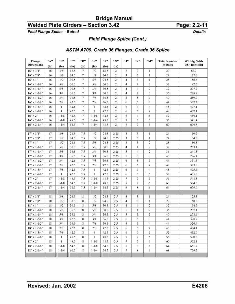
Bridge Manual Welded Plate Girders – Section 3.42 Page: 2.2-11 Field Flange Splice – Bolted Details
Revised: Jan. 2002 E4206
Field Flange Splice (Cont.)
ASTM A709, Grade 36 Flanges, Grade 36 Splice
Flange Dimensions
“A”
(in)
“B”
(in)
“C”
(in)
“D”
(in)
“E”
(in)
“F”
(in)
“G”
(in)
“J” “K” “M” Total Number of Bolts
Wt./Flg. With 7/8” Bolts (lb)
16" x 3/4" 16 3/8 18.5 7 1/2 18.5 2 2 2 1 20 87.2 16" x 7/8" 16 1/2 24.5 7 1/2 24.5 2 3 3 1 24 127.0 16" x 1" 16 1/2 30.5 7 5/8 24.5 2 4 3 1 28 156.6 16" x 1-1/8" 16 5/8 30.5 7 5/8 30.5 2 4 4 2 32 192.6 16" x 1-1/4" 16 5/8 30.5 7 3/4 30.5 2 4 4 2 32 207.7 16" x 1-3/8" 16 3/4 30.5 7 3/4 30.5 2 4 4 3 36 228.8 16" x 1-1/2" 16 3/4 36.5 7 7/8 36.5 2 5 5 3 40 289.0 16" x 1-5/8" 16 7/8 42.5 7 7/8 36.5 2 6 5 3 44 337.3 16" x 1-3/4" 16 1 42.5 7 1 42.5 2 6 6 4 48 407.1 16" x 1-7/8" 16 1 42.5 7 1 42.5 2 6 6 4 48 407.1 16" x 2" 16 1-1/8 42.5 7 1-1/8 42.5 2 6 6 5 52 456.1 16" x 2-1/8" 16 1-1/8 48.5 7 1-1/4 48.5 2 7 7 5 56 541.4 16" x 2-1/4" 16 1-1/4 54.5 7 1-1/4 48.5 2 8 7 5 60 606.8 17" x 3/4" 17 3/8 24.5 7.5 1/2 24.5 2.25 3 3 1 24 119.2 17" x 7/8" 17 1/2 24.5 7.5 1/2 24.5 2.25 3 3 1 24 134.0 17" x 1" 17 1/2 24.5 7.5 5/8 24.5 2.25 3 3 2 28 150.8 17" x 1-1/8" 17 5/8 30.5 7.5 5/8 30.5 2.25 4 4 2 32 203.4 17" x 1-1/4" 17 5/8 36.5 7.5 3/4 30.5 2.25 5 4 2 36 241.5 17" x 1-3/8" 17 3/4 36.5 7.5 3/4 36.5 2.25 5 5 3 40 286.4 17" x 1-1/2" 17 3/4 42.5 7.5 7/8 36.5 2.25 6 5 3 44 331.3 17" x 1-5/8" 17 7/8 42.5 7.5 7/8 42.5 2.25 6 6 4 48 383.0 17" x 1-3/4" 17 7/8 42.5 7.5 1 42.5 2.25 6 6 4 48 405.6 17" x 1-7/8" 17 1 42.5 7.5 1 42.5 2.25 6 6 5 52 435.0 17" x 2" 17 1-1/8 48.5 7.5 1-1/8 48.5 2.25 7 7 5 56 548.3 17" x 2-1/8" 17 1-1/8 54.5 7.5 1-1/8 48.5 2.25 8 7 5 60 584.6 17" x 2-1/4" 17 1-1/4 54.5 7.5 1-1/4 54.5 2.25 8 8 6 64 679.0 18" x 3/4" 18 3/8 24.5 8 1/2 24.5 2.5 3 3 1 24 125.3 18" x 7/8" 18 1/2 30.5 8 1/2 24.5 2.5 4 3 1 28 160.0 18" x 1" 18 1/2 30.5 8 5/8 30.5 2.5 4 4 2 32 194.7 18" x 1-1/8" 18 5/8 36.5 8 5/8 30.5 2.5 5 4 2 36 237.1 18" x 1-1/4" 18 5/8 36.5 8 3/4 36.5 2.5 5 5 3 40 278.6 18" x 1-3/8" 18 3/4 42.5 8 3/4 36.5 2.5 6 5 3 44 328.7 18" x 1-1/2" 18 3/4 36.5 8 7/8 36.5 2.5 5 5 4 44 326.4 18" x 1-5/8" 18 7/8 42.5 8 7/8 42.5 2.5 6 6 4 48 404.1 18" x 1-3/4" 18 7/8 42.5 8 1 42.5 2.5 6 6 5 52 432.0 18" x 1-7/8" 18 1 48.5 8 1 48.5 2.5 7 7 5 56 520.8 18" x 2" 18 1 48.5 8 1-1/8 48.5 2.5 7 7 6 60 552.1 18" x 2-1/8" 18 1-1/8 54.5 8 1-1/8 54.5 2.5 8 8 6 64 651.9 18" x 2-1/4" 18 1-1/4 60.5 8 1-1/4 54.5 2.5 9 8 6 68 759.7
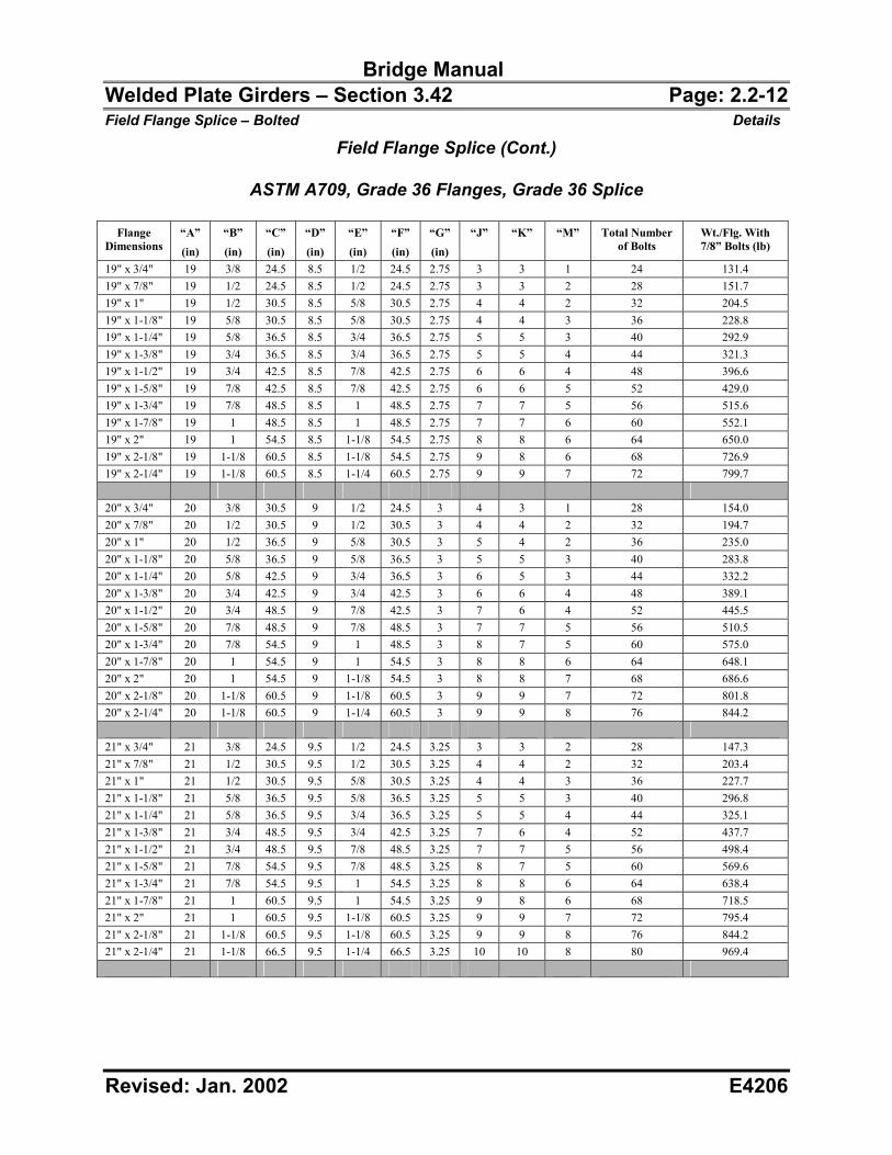
Bridge Manual Welded Plate Girders – Section 3.42 Page: 2.2-12 Field Flange Splice – Bolted Details
Revised: Jan. 2002 E4206
Field Flange Splice (Cont.)
ASTM A709, Grade 36 Flanges, Grade 36 Splice
Flange Dimensions
“A”
(in)
“B”
(in)
“C”
(in)
“D”
(in)
“E”
(in)
“F”
(in)
“G”
(in)
“J” “K” “M” Total Number of Bolts
Wt./Flg. With 7/8” Bolts (lb)
19" x 3/4" 19 3/8 24.5 8.5 1/2 24.5 2.75 3 3 1 24 131.4 19" x 7/8" 19 1/2 24.5 8.5 1/2 24.5 2.75 3 3 2 28 151.7 19" x 1" 19 1/2 30.5 8.5 5/8 30.5 2.75 4 4 2 32 204.5 19" x 1-1/8" 19 5/8 30.5 8.5 5/8 30.5 2.75 4 4 3 36 228.8 19" x 1-1/4" 19 5/8 36.5 8.5 3/4 36.5 2.75 5 5 3 40 292.9 19" x 1-3/8" 19 3/4 36.5 8.5 3/4 36.5 2.75 5 5 4 44 321.3 19" x 1-1/2" 19 3/4 42.5 8.5 7/8 42.5 2.75 6 6 4 48 396.6 19" x 1-5/8" 19 7/8 42.5 8.5 7/8 42.5 2.75 6 6 5 52 429.0 19" x 1-3/4" 19 7/8 48.5 8.5 1 48.5 2.75 7 7 5 56 515.6 19" x 1-7/8" 19 1 48.5 8.5 1 48.5 2.75 7 7 6 60 552.1 19" x 2" 19 1 54.5 8.5 1-1/8 54.5 2.75 8 8 6 64 650.0 19" x 2-1/8" 19 1-1/8 60.5 8.5 1-1/8 54.5 2.75 9 8 6 68 726.9 19" x 2-1/4" 19 1-1/8 60.5 8.5 1-1/4 60.5 2.75 9 9 7 72 799.7 20" x 3/4" 20 3/8 30.5 9 1/2 24.5 3 4 3 1 28 154.0 20" x 7/8" 20 1/2 30.5 9 1/2 30.5 3 4 4 2 32 194.7 20" x 1" 20 1/2 36.5 9 5/8 30.5 3 5 4 2 36 235.0 20" x 1-1/8" 20 5/8 36.5 9 5/8 36.5 3 5 5 3 40 283.8 20" x 1-1/4" 20 5/8 42.5 9 3/4 36.5 3 6 5 3 44 332.2 20" x 1-3/8" 20 3/4 42.5 9 3/4 42.5 3 6 6 4 48 389.1 20" x 1-1/2" 20 3/4 48.5 9 7/8 42.5 3 7 6 4 52 445.5 20" x 1-5/8" 20 7/8 48.5 9 7/8 48.5 3 7 7 5 56 510.5 20" x 1-3/4" 20 7/8 54.5 9 1 48.5 3 8 7 5 60 575.0 20" x 1-7/8" 20 1 54.5 9 1 54.5 3 8 8 6 64 648.1 20" x 2" 20 1 54.5 9 1-1/8 54.5 3 8 8 7 68 686.6 20" x 2-1/8" 20 1-1/8 60.5 9 1-1/8 60.5 3 9 9 7 72 801.8 20" x 2-1/4" 20 1-1/8 60.5 9 1-1/4 60.5 3 9 9 8 76 844.2 21" x 3/4" 21 3/8 24.5 9.5 1/2 24.5 3.25 3 3 2 28 147.3 21" x 7/8" 21 1/2 30.5 9.5 1/2 30.5 3.25 4 4 2 32 203.4 21" x 1" 21 1/2 30.5 9.5 5/8 30.5 3.25 4 4 3 36 227.7 21" x 1-1/8" 21 5/8 36.5 9.5 5/8 36.5 3.25 5 5 3 40 296.8 21" x 1-1/4" 21 5/8 36.5 9.5 3/4 36.5 3.25 5 5 4 44 325.1 21" x 1-3/8" 21 3/4 48.5 9.5 3/4 42.5 3.25 7 6 4 52 437.7 21" x 1-1/2" 21 3/4 48.5 9.5 7/8 48.5 3.25 7 7 5 56 498.4 21" x 1-5/8" 21 7/8 54.5 9.5 7/8 48.5 3.25 8 7 5 60 569.6 21" x 1-3/4" 21 7/8 54.5 9.5 1 54.5 3.25 8 8 6 64 638.4 21" x 1-7/8" 21 1 60.5 9.5 1 54.5 3.25 9 8 6 68 718.5 21" x 2" 21 1 60.5 9.5 1-1/8 60.5 3.25 9 9 7 72 795.4 21" x 2-1/8" 21 1-1/8 60.5 9.5 1-1/8 60.5 3.25 9 9 8 76 844.2 21" x 2-1/4" 21 1-1/8 66.5 9.5 1-1/4 66.5 3.25 10 10 8 80 969.4

Bridge Manual Welded Plate Girders – Section 3.42 Page: 2.2-13 Field Flange Splice – Bolted Details
Revised: Jan. 2002 E4206
Field Flange Splice (Cont.)
ASTM A709, Grade 36 Flanges, Grade 36 Splice
Flange Dimensions
“A”
(in)
“B”
(in)
“C”
(in)
“D”
(in)
“E”
(in)
“F”
(in)
“G”
(in)
“J” “K” “M” Total Number of Bolts
Wt./Flg. With 7/8” Bolts (lb)
22" x 3/4" 22 3/8 24.5 10 1/2 24.5 3.5 3 3 2 28 153.4 22" x 7/8" 22 1/2 36.5 10 1/2 30.5 3.5 5 4 2 36 234.5 22" x 1" 22 1/2 36.5 10 5/8 36.5 3.5 5 5 3 40 281.2 22" x 1-1/8" 22 5/8 42.5 10 5/8 36.5 3.5 6 5 3 44 336.9 22" x 1-1/4" 22 5/8 42.5 10 3/4 42.5 3.5 6 6 4 48 392.1 22" x 1-3/8" 22 3/4 42.5 10 3/4 42.5 3.5 6 6 5 52 429.0 22" x 1-1/2" 22 3/4 48.5 10 7/8 48.5 3.5 7 7 5 56 520.8 22" x 1-5/8" 22 7/8 54.5 10 7/8 54.5 3.5 8 8 6 64 628.7 22" x 1-3/4" 22 7/8 60.5 10 1 54.5 3.5 9 8 6 68 703.9 22" x 1-7/8" 22 1 60.5 10 1 60.5 3.5 9 9 7 72 788.9 22" x 2" 22 1 60.5 10 1-1/8 60.5 3.5 9 9 8 76 835.6 22" x 2-1/8" 22 1-1/8 66.5 10 1-1/8 66.5 3.5 10 10 8 80 967.0 22" x 2-1/4" 22 1-1/8 66.5 10 1-1/4 66.5 3.5 10 10 9 84 1017.9 23" x 3/4" 23 3/8 30.5 10.5 1/2 30.5 3.75 4 4 2 32 195.8 23" x 7/8" 23 1/2 30.5 10.5 1/2 30.5 3.75 4 4 3 36 224.5 23" x 1" 23 1/2 36.5 10.5 5/8 36.5 3.75 5 5 3 40 292.9 23" x 1-1/8" 23 5/8 42.5 10.5 5/8 42.5 3.75 6 6 4 48 377.0 23" x 1-1/4" 23 5/8 48.5 10.5 3/4 42.5 3.75 7 6 4 52 436.9 23" x 1-3/8" 23 3/4 48.5 10.5 3/4 48.5 3.75 7 7 5 56 507.0 23" x 1-1/2" 23 3/4 48.5 10.5 7/8 48.5 3.75 7 7 6 60 546.9 23" x 1-5/8" 23 7/8 54.5 10.5 7/8 54.5 3.75 8 8 6 64 655.8 23" x 1-3/4" 23 7/8 60.5 10.5 1 60.5 3.75 9 9 7 72 773.9 23" x 1-7/8" 23 1 66.5 10.5 1 60.5 3.75 10 9 7 76 866.2 23" x 2" 23 1 66.5 10.5 1-1/8 66.5 3.75 10 10 8 80 955.2 23" x 2-1/8" 23 1-1/8 66.5 10.5 1-1/8 66.5 3.75 10 10 9 84 1013.2 23" x 2-1/4" 23 1-1/8 78.5 10.5 1-1/4 72.5 3.75 12 11 9 92 1203.0 24" x 3/4" 24 3/8 30.5 11 1/2 30.5 4 4 4 2 32 203.4 24" x 7/8" 24 1/2 36.5 11 1/2 36.5 4 5 5 3 40 276.1 24" x 1" 24 1/2 42.5 11 5/8 36.5 4 6 5 3 44 328.7 24" x 1-1/8" 24 5/8 42.5 11 5/8 42.5 4 6 6 4 48 392.1 24" x 1-1/4" 24 5/8 42.5 11 3/4 42.5 4 6 6 5 52 429.0 24" x 1-3/8" 24 3/4 54.5 11 3/4 48.5 4 8 7 5 60 562.1 24" x 1-1/2" 24 3/4 54.5 11 7/8 54.5 4 8 8 6 64 636.5 24" x 1-5/8" 24 7/8 54.5 11 7/8 54.5 4 8 8 7 68 686.6 24" x 1-3/4" 24 7/8 66.5 11 1 60.5 4 10 9 7 76 845.6 24" x 1-7/8" 24 1 66.5 11 1 66.5 4 10 10 8 80 943.4 24" x 2" 24 1 66.5 11 1-1/8 66.5 4 10 10 9 84 999.1 24" x 2-1/8" 24 1-1/8 72.5 11 1-1/8 72.5 4 11 11 9 88 1147.5 24" x 2-1/4" 24 1-1/8 78.5 11 1-1/4 78.5 4 12 12 10 96 1304.4
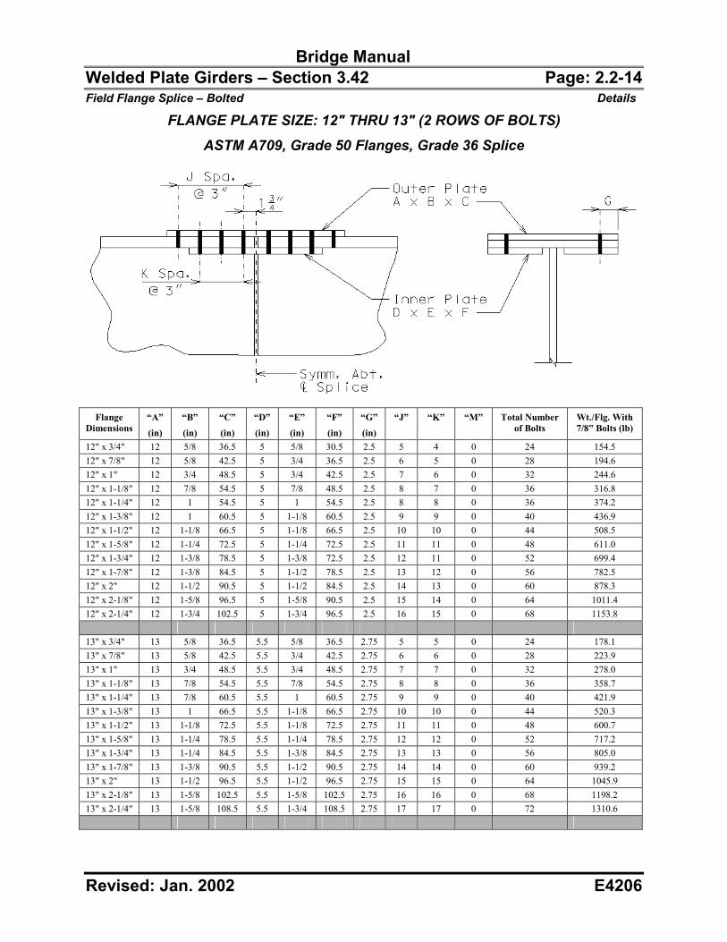
Bridge Manual Welded Plate Girders – Section 3.42 Page: 2.2-14 Field Flange Splice – Bolted Details
Revised: Jan. 2002 E4206
FLANGE PLATE SIZE: 12" THRU 13" (2 ROWS OF BOLTS) ASTM A709, Grade 50 Flanges, Grade 36 Splice
Flange
Dimensions “A”
(in)
“B”
(in)
“C”
(in)
“D”
(in)
“E”
(in)
“F”
(in)
“G”
(in)
“J” “K” “M” Total Number of Bolts
Wt./Flg. With 7/8” Bolts (lb)
12" x 3/4" 12 5/8 36.5 5 5/8 30.5 2.5 5 4 0 24 154.5 12" x 7/8" 12 5/8 42.5 5 3/4 36.5 2.5 6 5 0 28 194.6 12" x 1" 12 3/4 48.5 5 3/4 42.5 2.5 7 6 0 32 244.6 12" x 1-1/8" 12 7/8 54.5 5 7/8 48.5 2.5 8 7 0 36 316.8 12" x 1-1/4" 12 1 54.5 5 1 54.5 2.5 8 8 0 36 374.2 12" x 1-3/8" 12 1 60.5 5 1-1/8 60.5 2.5 9 9 0 40 436.9 12" x 1-1/2" 12 1-1/8 66.5 5 1-1/8 66.5 2.5 10 10 0 44 508.5 12" x 1-5/8" 12 1-1/4 72.5 5 1-1/4 72.5 2.5 11 11 0 48 611.0 12" x 1-3/4" 12 1-3/8 78.5 5 1-3/8 72.5 2.5 12 11 0 52 699.4 12" x 1-7/8" 12 1-3/8 84.5 5 1-1/2 78.5 2.5 13 12 0 56 782.5 12" x 2" 12 1-1/2 90.5 5 1-1/2 84.5 2.5 14 13 0 60 878.3 12" x 2-1/8" 12 1-5/8 96.5 5 1-5/8 90.5 2.5 15 14 0 64 1011.4 12" x 2-1/4" 12 1-3/4 102.5 5 1-3/4 96.5 2.5 16 15 0 68 1153.8 13" x 3/4" 13 5/8 36.5 5.5 5/8 36.5 2.75 5 5 0 24 178.1 13" x 7/8" 13 5/8 42.5 5.5 3/4 42.5 2.75 6 6 0 28 223.9 13" x 1" 13 3/4 48.5 5.5 3/4 48.5 2.75 7 7 0 32 278.0 13" x 1-1/8" 13 7/8 54.5 5.5 7/8 54.5 2.75 8 8 0 36 358.7 13" x 1-1/4" 13 7/8 60.5 5.5 1 60.5 2.75 9 9 0 40 421.9 13" x 1-3/8" 13 1 66.5 5.5 1-1/8 66.5 2.75 10 10 0 44 520.3 13" x 1-1/2" 13 1-1/8 72.5 5.5 1-1/8 72.5 2.75 11 11 0 48 600.7 13" x 1-5/8" 13 1-1/4 78.5 5.5 1-1/4 78.5 2.75 12 12 0 52 717.2 13" x 1-3/4" 13 1-1/4 84.5 5.5 1-3/8 84.5 2.75 13 13 0 56 805.0 13" x 1-7/8" 13 1-3/8 90.5 5.5 1-1/2 90.5 2.75 14 14 0 60 939.2 13" x 2" 13 1-1/2 96.5 5.5 1-1/2 96.5 2.75 15 15 0 64 1045.9 13" x 2-1/8" 13 1-5/8 102.5 5.5 1-5/8 102.5 2.75 16 16 0 68 1198.2 13" x 2-1/4" 13 1-5/8 108.5 5.5 1-3/4 108.5 2.75 17 17 0 72 1310.6
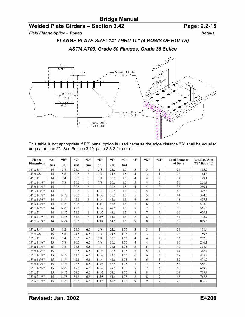
Bridge Manual Welded Plate Girders – Section 3.42 Page: 2.2-15 Field Flange Splice – Bolted Details
Revised: Jan. 2002 E4206
FLANGE PLATE SIZE: 14" THRU 15" (4 ROWS OF BOLTS) ASTM A709, Grade 50 Flanges, Grade 36 Splice
This table is not appropriate if P/S panel option is used because the edge distance "G" shall be equal to or greater than 2". See Section 3.40 page 3.3-2 for detail.
Flange Dimensions
“A”
(in)
“B”
(in)
“C”
(in)
“D”
(in)
“E”
(in)
“F”
(in)
“G”
(in)
“J” “K” “M” Total Number of Bolts
Wt./Flg. With 7/8” Bolts (lb)
14" x 3/4" 14 5/8 24.5 6 5/8 24.5 1.5 3 3 1 24 135.7 14" x 7/8" 14 5/8 30.5 6 3/4 24.5 1.5 4 3 1 28 164.8 14" x 1" 14 3/4 30.5 6 3/4 30.5 1.5 4 4 2 32 199.1 14" x 1-1/8" 14 7/8 36.5 6 7/8 30.5 1.5 5 4 2 36 251.8 14" x 1-1/4" 14 1 30.5 6 1 30.5 1.5 4 4 3 36 259.1 14" x 1-3/8" 14 1 36.5 6 1-1/8 36.5 1.5 5 5 3 40 322.6 14" x 1-1/2" 14 1-1/8 36.5 6 1-1/8 36.5 1.5 5 5 4 44 344.5 14" x 1-5/8" 14 1-1/4 42.5 6 1-1/4 42.5 1.5 6 6 4 48 437.3 14" x 1-3/4" 14 1-3/8 48.5 6 1-3/8 42.5 1.5 7 6 4 52 513.0 14" x 1-7/8" 14 1-3/8 48.5 6 1-1/2 48.5 1.5 7 7 5 56 565.5 14" x 2" 14 1-1/2 54.5 6 1-1/2 48.5 1.5 8 7 5 60 629.1 14" x 2-1/8" 14 1-5/8 54.5 6 1-5/8 54.5 1.5 8 8 6 64 713.7 14" x 2-1/4" 14 1-3/4 60.5 6 1-3/4 54.5 1.5 9 8 6 68 809.5 15" x 3/4" 15 1/2 24.5 6.5 5/8 24.5 1.75 3 3 1 24 131.4 15" x 7/8" 15 5/8 24.5 6.5 3/4 24.5 1.75 3 3 2 28 159.5 15" x 1" 15 3/4 30.5 6.5 3/4 30.5 1.75 4 4 2 32 212.0 15" x 1-1/8" 15 7/8 30.5 6.5 7/8 30.5 1.75 4 4 3 36 246.1 15" x 1-1/4" 15 7/8 36.5 6.5 1 36.5 1.75 5 5 3 40 308.4 15" x 1-3/8" 15 1 36.5 6.5 1-1/8 36.5 1.75 5 5 4 44 348.4 15" x 1-1/2" 15 1-1/8 42.5 6.5 1-1/8 42.5 1.75 6 6 4 48 425.2 15" x 1-5/8" 15 1-1/4 42.5 6.5 1-1/4 42.5 1.75 6 6 5 52 471.2 15" x 1-3/4" 15 1-1/4 48.5 6.5 1-3/8 48.5 1.75 7 7 5 56 556.9 15" x 1-7/8" 15 1-3/8 48.5 6.5 1-1/2 48.5 1.75 7 7 6 60 608.8 15" x 2" 15 1-1/2 54.5 6.5 1-1/2 54.5 1.75 8 8 6 64 709.9 15" x 2-1/8" 15 1-5/8 54.5 6.5 1-5/8 54.5 1.75 8 8 7 68 767.8 15" x 2-1/4" 15 1-5/8 60.5 6.5 1-3/4 60.5 1.75 9 9 7 72 876.9
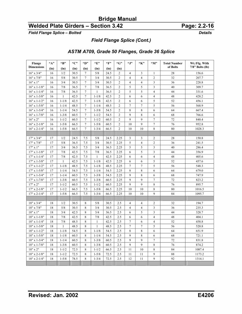
Bridge Manual Welded Plate Girders – Section 3.42 Page: 2.2-16 Field Flange Splice – Bolted Details
Revised: Jan. 2002 E4206
Field Flange Splice (Cont.)
ASTM A709, Grade 50 Flanges, Grade 36 Splice
Flange Dimensions
“A”
(in)
“B”
(in)
“C”
(in)
“D”
(in)
“E”
(in)
“F”
(in)
“G”
(in)
“J” “K” “M” Total Number of Bolts
Wt./Flg. With 7/8” Bolts (lb)
16" x 3/4" 16 1/2 30.5 7 5/8 24.5 2 4 3 1 28 156.6 16" x 7/8" 16 5/8 30.5 7 3/4 30.5 2 4 4 2 32 207.7 16" x 1" 16 3/4 30.5 7 3/4 30.5 2 4 4 3 36 228.8 16" x 1-1/8" 16 7/8 36.5 7 7/8 36.5 2 5 5 3 40 309.7 16" x 1-1/4" 16 7/8 36.5 7 1 36.5 2 5 5 4 44 331.6 16" x 1-3/8" 16 1 42.5 7 1-1/8 42.5 2 6 6 4 48 428.2 16" x 1-1/2" 16 1-1/8 42.5 7 1-1/8 42.5 2 6 6 5 52 456.1 16" x 1-5/8" 16 1-1/4 48.5 7 1-1/4 48.5 2 7 7 5 56 568.9 16" x 1-3/4" 16 1-1/4 54.5 7 1-3/8 54.5 2 8 8 6 64 667.4 16" x 1-7/8" 16 1-3/8 60.5 7 1-1/2 54.5 2 9 8 6 68 766.6 16" x 2" 16 1-1/2 60.5 7 1-1/2 60.5 2 9 9 7 72 840.4 16" x 2-1/8" 16 1-5/8 66.5 7 1-5/8 60.5 2 10 9 7 76 952.8 16" x 2-1/4" 16 1-5/8 66.5 7 1-3/4 66.5 2 10 10 8 80 1028.3 17" x 3/4" 17 1/2 24.5 7.5 5/8 24.5 2.25 3 3 2 28 150.8 17" x 7/8" 17 5/8 36.5 7.5 3/4 30.5 2.25 5 4 2 36 241.5 17" x 1" 17 3/4 36.5 7.5 3/4 36.5 2.25 5 5 3 40 286.4 17" x 1-1/8" 17 7/8 42.5 7.5 7/8 36.5 2.25 6 5 3 44 356.9 17" x 1-1/4" 17 7/8 42.5 7.5 1 42.5 2.25 6 6 4 48 405.6 17" x 1-3/8" 17 1 42.5 7.5 1-1/8 42.5 2.25 6 6 5 52 457.6 17" x 1-1/2" 17 1-1/8 48.5 7.5 1-1/8 48.5 2.25 7 7 5 56 548.3 17" x 1-5/8" 17 1-1/4 54.5 7.5 1-1/4 54.5 2.25 8 8 6 64 679.0 17" x 1-3/4" 17 1-1/4 60.5 7.5 1-3/8 54.5 2.25 9 8 6 68 747.9 17" x 1-7/8" 17 1-3/8 60.5 7.5 1-3/8 60.5 2.25 9 9 7 72 823.2 17" x 2" 17 1-1/2 60.5 7.5 1-1/2 60.5 2.25 9 9 8 76 895.7 17" x 2-1/8" 17 1-1/2 66.5 7.5 1-5/8 66.5 2.25 10 10 8 80 1016.5 17" x 2-1/4" 17 1-5/8 66.5 7.5 1-3/4 66.5 2.25 10 10 9 84 1095.7 18" x 3/4" 18 1/2 30.5 8 5/8 30.5 2.5 4 4 2 32 194.7 18" x 7/8" 18 5/8 30.5 8 3/4 30.5 2.5 4 4 3 36 235.3 18" x 1" 18 3/4 42.5 8 3/4 36.5 2.5 6 5 3 44 328.7 18" x 1-1/8" 18 7/8 42.5 8 7/8 42.5 2.5 6 6 4 48 404.1 18" x 1-1/4" 18 7/8 48.5 8 1 42.5 2.5 7 6 4 52 458.8 18" x 1-3/8" 18 1 48.5 8 1 48.5 2.5 7 7 5 56 520.8 18" x 1-1/2" 18 1-1/8 54.5 8 1-1/8 54.5 2.5 8 8 6 64 651.9 18" x 1-5/8" 18 1-1/8 60.5 8 1-1/4 54.5 2.5 9 8 6 68 721.1 18" x 1-3/4" 18 1-1/4 60.5 8 1-3/8 60.5 2.5 9 9 7 72 831.8 18" x 1-7/8" 18 1-3/8 60.5 8 1-3/8 60.5 2.5 9 9 8 76 874.2 18" x 2" 18 1-1/2 72.5 8 1-1/2 66.5 2.5 11 10 8 84 1087.4 18" x 2-1/8" 18 1-1/2 72.5 8 1-5/8 72.5 2.5 11 11 9 88 1173.2 18" x 2-1/4" 18 1-5/8 78.5 8 1-3/4 72.5 2.5 12 11 9 92 1314.1
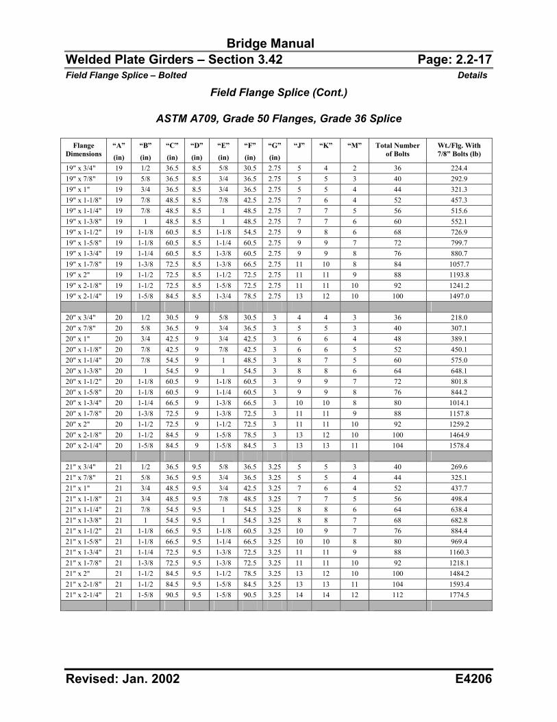
Bridge Manual Welded Plate Girders – Section 3.42 Page: 2.2-17 Field Flange Splice – Bolted Details
Revised: Jan. 2002 E4206
Field Flange Splice (Cont.)
ASTM A709, Grade 50 Flanges, Grade 36 Splice
Flange Dimensions
“A”
(in)
“B”
(in)
“C”
(in)
“D”
(in)
“E”
(in)
“F”
(in)
“G”
(in)
“J” “K” “M” Total Number of Bolts
Wt./Flg. With 7/8” Bolts (lb)
19" x 3/4" 19 1/2 36.5 8.5 5/8 30.5 2.75 5 4 2 36 224.4 19" x 7/8" 19 5/8 36.5 8.5 3/4 36.5 2.75 5 5 3 40 292.9 19" x 1" 19 3/4 36.5 8.5 3/4 36.5 2.75 5 5 4 44 321.3 19" x 1-1/8" 19 7/8 48.5 8.5 7/8 42.5 2.75 7 6 4 52 457.3 19" x 1-1/4" 19 7/8 48.5 8.5 1 48.5 2.75 7 7 5 56 515.6 19" x 1-3/8" 19 1 48.5 8.5 1 48.5 2.75 7 7 6 60 552.1 19" x 1-1/2" 19 1-1/8 60.5 8.5 1-1/8 54.5 2.75 9 8 6 68 726.9 19" x 1-5/8" 19 1-1/8 60.5 8.5 1-1/4 60.5 2.75 9 9 7 72 799.7 19" x 1-3/4" 19 1-1/4 60.5 8.5 1-3/8 60.5 2.75 9 9 8 76 880.7 19" x 1-7/8" 19 1-3/8 72.5 8.5 1-3/8 66.5 2.75 11 10 8 84 1057.7 19" x 2" 19 1-1/2 72.5 8.5 1-1/2 72.5 2.75 11 11 9 88 1193.8 19" x 2-1/8" 19 1-1/2 72.5 8.5 1-5/8 72.5 2.75 11 11 10 92 1241.2 19" x 2-1/4" 19 1-5/8 84.5 8.5 1-3/4 78.5 2.75 13 12 10 100 1497.0 20" x 3/4" 20 1/2 30.5 9 5/8 30.5 3 4 4 3 36 218.0 20" x 7/8" 20 5/8 36.5 9 3/4 36.5 3 5 5 3 40 307.1 20" x 1" 20 3/4 42.5 9 3/4 42.5 3 6 6 4 48 389.1 20" x 1-1/8" 20 7/8 42.5 9 7/8 42.5 3 6 6 5 52 450.1 20" x 1-1/4" 20 7/8 54.5 9 1 48.5 3 8 7 5 60 575.0 20" x 1-3/8" 20 1 54.5 9 1 54.5 3 8 8 6 64 648.1 20" x 1-1/2" 20 1-1/8 60.5 9 1-1/8 60.5 3 9 9 7 72 801.8 20" x 1-5/8" 20 1-1/8 60.5 9 1-1/4 60.5 3 9 9 8 76 844.2 20" x 1-3/4" 20 1-1/4 66.5 9 1-3/8 66.5 3 10 10 8 80 1014.1 20" x 1-7/8" 20 1-3/8 72.5 9 1-3/8 72.5 3 11 11 9 88 1157.8 20" x 2" 20 1-1/2 72.5 9 1-1/2 72.5 3 11 11 10 92 1259.2 20" x 2-1/8" 20 1-1/2 84.5 9 1-5/8 78.5 3 13 12 10 100 1464.9 20" x 2-1/4" 20 1-5/8 84.5 9 1-5/8 84.5 3 13 13 11 104 1578.4 21" x 3/4" 21 1/2 36.5 9.5 5/8 36.5 3.25 5 5 3 40 269.6 21" x 7/8" 21 5/8 36.5 9.5 3/4 36.5 3.25 5 5 4 44 325.1 21" x 1" 21 3/4 48.5 9.5 3/4 42.5 3.25 7 6 4 52 437.7 21" x 1-1/8" 21 3/4 48.5 9.5 7/8 48.5 3.25 7 7 5 56 498.4 21" x 1-1/4" 21 7/8 54.5 9.5 1 54.5 3.25 8 8 6 64 638.4 21" x 1-3/8" 21 1 54.5 9.5 1 54.5 3.25 8 8 7 68 682.8 21" x 1-1/2" 21 1-1/8 66.5 9.5 1-1/8 60.5 3.25 10 9 7 76 884.4 21" x 1-5/8" 21 1-1/8 66.5 9.5 1-1/4 66.5 3.25 10 10 8 80 969.4 21" x 1-3/4" 21 1-1/4 72.5 9.5 1-3/8 72.5 3.25 11 11 9 88 1160.3 21" x 1-7/8" 21 1-3/8 72.5 9.5 1-3/8 72.5 3.25 11 11 10 92 1218.1 21" x 2" 21 1-1/2 84.5 9.5 1-1/2 78.5 3.25 13 12 10 100 1484.2 21" x 2-1/8" 21 1-1/2 84.5 9.5 1-5/8 84.5 3.25 13 13 11 104 1593.4 21" x 2-1/4" 21 1-5/8 90.5 9.5 1-5/8 90.5 3.25 14 14 12 112 1774.5
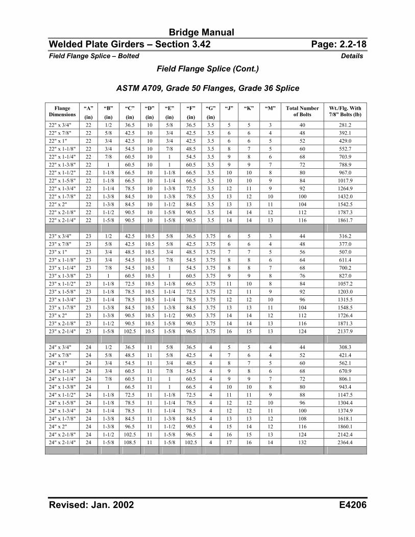
Bridge Manual Welded Plate Girders – Section 3.42 Page: 2.2-18 Field Flange Splice – Bolted Details
Revised: Jan. 2002 E4206
Field Flange Splice (Cont.)
ASTM A709, Grade 50 Flanges, Grade 36 Splice
Flange Dimensions
“A”
(in)
“B”
(in)
“C”
(in)
“D”
(in)
“E”
(in)
“F”
(in)
“G”
(in)
“J” “K” “M” Total Number of Bolts
Wt./Flg. With 7/8” Bolts (lb)
22" x 3/4" 22 1/2 36.5 10 5/8 36.5 3.5 5 5 3 40 281.2 22" x 7/8" 22 5/8 42.5 10 3/4 42.5 3.5 6 6 4 48 392.1 22" x 1" 22 3/4 42.5 10 3/4 42.5 3.5 6 6 5 52 429.0 22" x 1-1/8" 22 3/4 54.5 10 7/8 48.5 3.5 8 7 5 60 552.7 22" x 1-1/4" 22 7/8 60.5 10 1 54.5 3.5 9 8 6 68 703.9 22" x 1-3/8" 22 1 60.5 10 1 60.5 3.5 9 9 7 72 788.9 22" x 1-1/2" 22 1-1/8 66.5 10 1-1/8 66.5 3.5 10 10 8 80 967.0 22" x 1-5/8" 22 1-1/8 66.5 10 1-1/4 66.5 3.5 10 10 9 84 1017.9 22" x 1-3/4" 22 1-1/4 78.5 10 1-3/8 72.5 3.5 12 11 9 92 1264.9 22" x 1-7/8" 22 1-3/8 84.5 10 1-3/8 78.5 3.5 13 12 10 100 1432.0 22" x 2" 22 1-3/8 84.5 10 1-1/2 84.5 3.5 13 13 11 104 1542.5 22" x 2-1/8" 22 1-1/2 90.5 10 1-5/8 90.5 3.5 14 14 12 112 1787.3 22" x 2-1/4" 22 1-5/8 90.5 10 1-5/8 90.5 3.5 14 14 13 116 1861.7 23" x 3/4" 23 1/2 42.5 10.5 5/8 36.5 3.75 6 5 3 44 316.2 23" x 7/8" 23 5/8 42.5 10.5 5/8 42.5 3.75 6 6 4 48 377.0 23" x 1" 23 3/4 48.5 10.5 3/4 48.5 3.75 7 7 5 56 507.0 23" x 1-1/8" 23 3/4 54.5 10.5 7/8 54.5 3.75 8 8 6 64 611.4 23" x 1-1/4" 23 7/8 54.5 10.5 1 54.5 3.75 8 8 7 68 700.2 23" x 1-3/8" 23 1 60.5 10.5 1 60.5 3.75 9 9 8 76 827.0 23" x 1-1/2" 23 1-1/8 72.5 10.5 1-1/8 66.5 3.75 11 10 8 84 1057.2 23" x 1-5/8" 23 1-1/8 78.5 10.5 1-1/4 72.5 3.75 12 11 9 92 1203.0 23" x 1-3/4" 23 1-1/4 78.5 10.5 1-1/4 78.5 3.75 12 12 10 96 1315.5 23" x 1-7/8" 23 1-3/8 84.5 10.5 1-3/8 84.5 3.75 13 13 11 104 1548.5 23" x 2" 23 1-3/8 90.5 10.5 1-1/2 90.5 3.75 14 14 12 112 1726.4 23" x 2-1/8" 23 1-1/2 90.5 10.5 1-5/8 90.5 3.75 14 14 13 116 1871.3 23" x 2-1/4" 23 1-5/8 102.5 10.5 1-5/8 96.5 3.75 16 15 13 124 2137.9 24" x 3/4" 24 1/2 36.5 11 5/8 36.5 4 5 5 4 44 308.3 24" x 7/8" 24 5/8 48.5 11 5/8 42.5 4 7 6 4 52 421.4 24" x 1" 24 3/4 54.5 11 3/4 48.5 4 8 7 5 60 562.1 24" x 1-1/8" 24 3/4 60.5 11 7/8 54.5 4 9 8 6 68 670.9 24" x 1-1/4" 24 7/8 60.5 11 1 60.5 4 9 9 7 72 806.1 24" x 1-3/8" 24 1 66.5 11 1 66.5 4 10 10 8 80 943.4 24" x 1-1/2" 24 1-1/8 72.5 11 1-1/8 72.5 4 11 11 9 88 1147.5 24" x 1-5/8" 24 1-1/8 78.5 11 1-1/4 78.5 4 12 12 10 96 1304.4 24" x 1-3/4" 24 1-1/4 78.5 11 1-1/4 78.5 4 12 12 11 100 1374.9 24" x 1-7/8" 24 1-3/8 84.5 11 1-3/8 84.5 4 13 13 12 108 1618.1 24" x 2" 24 1-3/8 96.5 11 1-1/2 90.5 4 15 14 12 116 1860.1 24" x 2-1/8" 24 1-1/2 102.5 11 1-5/8 96.5 4 16 15 13 124 2142.4 24" x 2-1/4" 24 1-5/8 108.5 11 1-5/8 102.5 4 17 16 14 132 2364.4
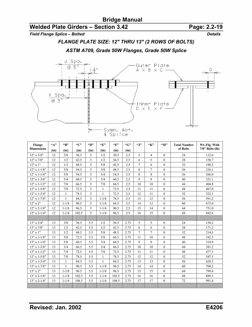
Bridge Manual Welded Plate Girders – Section 3.42 Page: 2.2-19 Field Flange Splice – Bolted Details
Revised: Jan. 2002 E4206
FLANGE PLATE SIZE: 12" THRU 13" (2 ROWS OF BOLTS) ASTM A709, Grade 50W Flanges, Grade 50W Splice
Flange
Dimensions “A”
(in)
“B”
(in)
“C”
(in)
“D”
(in)
“E”
(in)
“F”
(in)
“G”
(in)
“J” “K” “M” Total Number of Bolts
Wt./Flg. With 7/8” Bolts (lb)
12" x 3/4" 12 3/8 36.5 5 1/2 30.5 2.5 5 4 0 24 112.6 12" x 7/8" 12 1/2 42.5 5 1/2 36.5 2.5 6 5 0 28 150.7 12" x 1" 12 1/2 48.5 5 5/8 42.5 2.5 7 6 0 32 188.2 12" x 1-1/8" 12 5/8 54.5 5 5/8 48.5 2.5 8 7 0 36 236.1 12" x 1-1/4" 12 5/8 54.5 5 3/4 54.5 2.5 8 8 0 36 266.0 12" x 1-3/8" 12 3/4 60.5 5 3/4 60.5 2.5 9 9 0 40 321.1 12" x 1-1/2" 12 7/8 66.5 5 7/8 66.5 2.5 10 10 0 44 404.8 12" x 1-5/8" 12 7/8 72.5 5 1 72.5 2.5 11 11 0 48 467.0 12" x 1-3/4" 12 1 78.5 5 1 72.5 2.5 12 11 0 52 522.1 12" x 1-7/8" 12 1 84.5 5 1-1/8 78.5 2.5 13 12 0 56 591.2 12" x 2" 12 1-1/8 90.5 5 1-1/8 84.5 2.5 14 13 0 60 673.0 12" x 2-1/8" 12 1-1/8 96.5 5 1-1/4 90.5 2.5 15 14 0 64 751.0 12" x 2-1/4" 12 1-1/4 102.5 5 1-1/4 96.5 2.5 16 15 0 68 842.6 13" x 3/4" 13 3/8 36.5 5.5 1/2 36.5 2.75 5 5 0 24 130.2 13" x 7/8" 13 1/2 42.5 5.5 1/2 42.5 2.75 6 6 0 28 171.2 13" x 1" 13 1/2 48.5 5.5 5/8 48.5 2.75 7 7 0 32 214.3 13" x 1-1/8" 13 5/8 72.5 5.5 5/8 66.5 2.75 11 10 0 48 342.3 13" x 1-1/4" 13 5/8 60.5 5.5 3/4 60.5 2.75 9 9 0 40 318.9 13" x 1-3/8" 13 3/4 66.5 5.5 3/4 66.5 2.75 10 10 0 44 381.2 13" x 1-1/2" 13 7/8 72.5 5.5 7/8 72.5 2.75 11 11 0 48 477.3 13" x 1-5/8" 13 7/8 78.5 5.5 1 78.5 2.75 12 12 0 52 547.5 13" x 1-3/4" 13 1 84.5 5.5 1 84.5 2.75 13 13 0 56 628.3 13" x 1-7/8" 13 1 90.5 5.5 1-1/8 90.5 2.75 14 14 0 60 708.2 13" x 2" 13 1-1/8 96.5 5.5 1-1/8 96.5 2.75 15 15 0 64 799.6 13" x 2-1/8" 13 1-1/8 102.5 5.5 1-1/4 102.5 2.75 16 16 0 68 889.3 13" x 2-1/4" 13 1-1/4 108.5 5.5 1-1/4 108.5 2.75 17 17 0 72 991.4
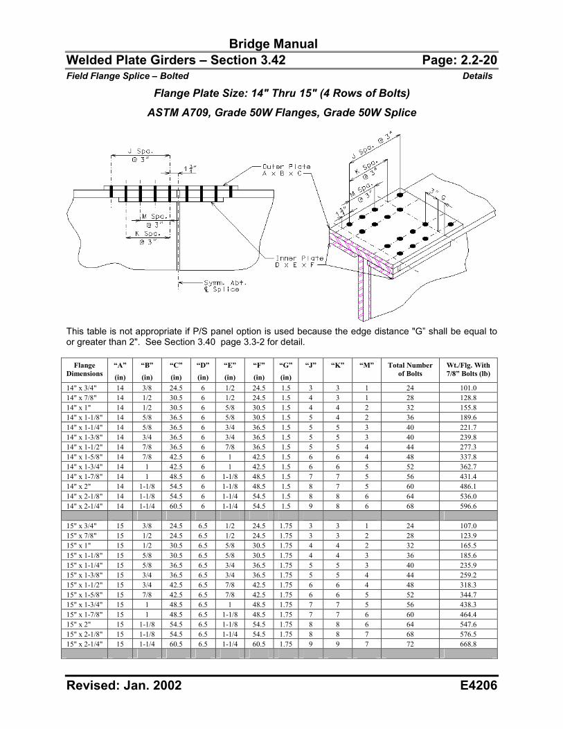
Bridge Manual Welded Plate Girders – Section 3.42 Page: 2.2-20 Field Flange Splice – Bolted Details
Revised: Jan. 2002 E4206
Flange Plate Size: 14" Thru 15" (4 Rows of Bolts) ASTM A709, Grade 50W Flanges, Grade 50W Splice
This table is not appropriate if P/S panel option is used because the edge distance "G” shall be equal to or greater than 2". See Section 3.40 page 3.3-2 for detail.
Flange Dimensions
“A”
(in)
“B”
(in)
“C”
(in)
“D”
(in)
“E”
(in)
“F”
(in)
“G”
(in)
“J” “K” “M” Total Number of Bolts
Wt./Flg. With 7/8” Bolts (lb)
14" x 3/4" 14 3/8 24.5 6 1/2 24.5 1.5 3 3 1 24 101.0 14" x 7/8" 14 1/2 30.5 6 1/2 24.5 1.5 4 3 1 28 128.8 14" x 1" 14 1/2 30.5 6 5/8 30.5 1.5 4 4 2 32 155.8 14" x 1-1/8" 14 5/8 36.5 6 5/8 30.5 1.5 5 4 2 36 189.6 14" x 1-1/4" 14 5/8 36.5 6 3/4 36.5 1.5 5 5 3 40 221.7 14" x 1-3/8" 14 3/4 36.5 6 3/4 36.5 1.5 5 5 3 40 239.8 14" x 1-1/2" 14 7/8 36.5 6 7/8 36.5 1.5 5 5 4 44 277.3 14" x 1-5/8" 14 7/8 42.5 6 1 42.5 1.5 6 6 4 48 337.8 14" x 1-3/4" 14 1 42.5 6 1 42.5 1.5 6 6 5 52 362.7 14" x 1-7/8" 14 1 48.5 6 1-1/8 48.5 1.5 7 7 5 56 431.4 14" x 2" 14 1-1/8 54.5 6 1-1/8 48.5 1.5 8 7 5 60 486.1 14" x 2-1/8" 14 1-1/8 54.5 6 1-1/4 54.5 1.5 8 8 6 64 536.0 14" x 2-1/4" 14 1-1/4 60.5 6 1-1/4 54.5 1.5 9 8 6 68 596.6 15" x 3/4" 15 3/8 24.5 6.5 1/2 24.5 1.75 3 3 1 24 107.0 15" x 7/8" 15 1/2 24.5 6.5 1/2 24.5 1.75 3 3 2 28 123.9 15" x 1" 15 1/2 30.5 6.5 5/8 30.5 1.75 4 4 2 32 165.5 15" x 1-1/8" 15 5/8 30.5 6.5 5/8 30.5 1.75 4 4 3 36 185.6 15" x 1-1/4" 15 5/8 36.5 6.5 3/4 36.5 1.75 5 5 3 40 235.9 15" x 1-3/8" 15 3/4 36.5 6.5 3/4 36.5 1.75 5 5 4 44 259.2 15" x 1-1/2" 15 3/4 42.5 6.5 7/8 42.5 1.75 6 6 4 48 318.3 15" x 1-5/8" 15 7/8 42.5 6.5 7/8 42.5 1.75 6 6 5 52 344.7 15" x 1-3/4" 15 1 48.5 6.5 1 48.5 1.75 7 7 5 56 438.3 15" x 1-7/8" 15 1 48.5 6.5 1-1/8 48.5 1.75 7 7 6 60 464.4 15" x 2" 15 1-1/8 54.5 6.5 1-1/8 54.5 1.75 8 8 6 64 547.6 15" x 2-1/8" 15 1-1/8 54.5 6.5 1-1/4 54.5 1.75 8 8 7 68 576.5 15" x 2-1/4" 15 1-1/4 60.5 6.5 1-1/4 60.5 1.75 9 9 7 72 668.8
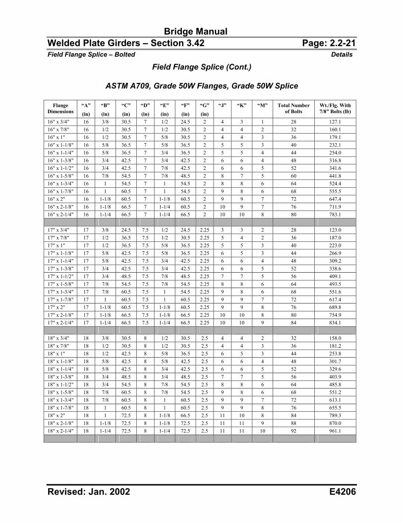
Bridge Manual Welded Plate Girders – Section 3.42 Page: 2.2-21 Field Flange Splice – Bolted Details
Revised: Jan. 2002 E4206
Field Flange Splice (Cont.)
ASTM A709, Grade 50W Flanges, Grade 50W Splice
Flange Dimensions
“A”
(in)
“B”
(in)
“C”
(in)
“D”
(in)
“E”
(in)
“F”
(in)
“G”
(in)
“J” “K” “M” Total Number of Bolts
Wt./Flg. With 7/8” Bolts (lb)
16" x 3/4" 16 3/8 30.5 7 1/2 24.5 2 4 3 1 28 127.1 16" x 7/8" 16 1/2 30.5 7 1/2 30.5 2 4 4 2 32 160.1 16" x 1" 16 1/2 30.5 7 5/8 30.5 2 4 4 3 36 179.1 16" x 1-1/8" 16 5/8 36.5 7 5/8 36.5 2 5 5 3 40 232.1 16" x 1-1/4" 16 5/8 36.5 7 3/4 36.5 2 5 5 4 44 254.0 16" x 1-3/8" 16 3/4 42.5 7 3/4 42.5 2 6 6 4 48 316.8 16" x 1-1/2" 16 3/4 42.5 7 7/8 42.5 2 6 6 5 52 341.6 16" x 1-5/8" 16 7/8 54.5 7 7/8 48.5 2 8 7 5 60 441.8 16" x 1-3/4" 16 1 54.5 7 1 54.5 2 8 8 6 64 524.4 16" x 1-7/8" 16 1 60.5 7 1 54.5 2 9 8 6 68 555.5 16" x 2" 16 1-1/8 60.5 7 1-1/8 60.5 2 9 9 7 72 647.4 16" x 2-1/8" 16 1-1/8 66.5 7 1-1/4 60.5 2 10 9 7 76 711.9 16" x 2-1/4" 16 1-1/4 66.5 7 1-1/4 66.5 2 10 10 8 80 783.1 17" x 3/4" 17 3/8 24.5 7.5 1/2 24.5 2.25 3 3 2 28 123.0 17" x 7/8" 17 1/2 36.5 7.5 1/2 30.5 2.25 5 4 2 36 187.0 17" x 1" 17 1/2 36.5 7.5 5/8 36.5 2.25 5 5 3 40 223.0 17" x 1-1/8" 17 5/8 42.5 7.5 5/8 36.5 2.25 6 5 3 44 266.9 17" x 1-1/4" 17 5/8 42.5 7.5 3/4 42.5 2.25 6 6 4 48 309.2 17" x 1-3/8" 17 3/4 42.5 7.5 3/4 42.5 2.25 6 6 5 52 338.6 17" x 1-1/2" 17 3/4 48.5 7.5 7/8 48.5 2.25 7 7 5 56 409.1 17" x 1-5/8" 17 7/8 54.5 7.5 7/8 54.5 2.25 8 8 6 64 493.5 17" x 1-3/4" 17 7/8 60.5 7.5 1 54.5 2.25 9 8 6 68 551.6 17" x 1-7/8" 17 1 60.5 7.5 1 60.5 2.25 9 9 7 72 617.4 17" x 2" 17 1-1/8 60.5 7.5 1-1/8 60.5 2.25 9 9 8 76 689.8 17" x 2-1/8" 17 1-1/8 66.5 7.5 1-1/8 66.5 2.25 10 10 8 80 754.9 17" x 2-1/4" 17 1-1/4 66.5 7.5 1-1/4 66.5 2.25 10 10 9 84 834.1 18" x 3/4" 18 3/8 30.5 8 1/2 30.5 2.5 4 4 2 32 158.0 18" x 7/8" 18 1/2 30.5 8 1/2 30.5 2.5 4 4 3 36 181.2 18" x 1" 18 1/2 42.5 8 5/8 36.5 2.5 6 5 3 44 253.8 18" x 1-1/8" 18 5/8 42.5 8 5/8 42.5 2.5 6 6 4 48 301.7 18" x 1-1/4" 18 5/8 42.5 8 3/4 42.5 2.5 6 6 5 52 329.6 18" x 1-3/8" 18 3/4 48.5 8 3/4 48.5 2.5 7 7 5 56 403.9 18" x 1-1/2" 18 3/4 54.5 8 7/8 54.5 2.5 8 8 6 64 485.8 18" x 1-5/8" 18 7/8 60.5 8 7/8 54.5 2.5 9 8 6 68 551.2 18" x 1-3/4" 18 7/8 60.5 8 1 60.5 2.5 9 9 7 72 613.1 18" x 1-7/8" 18 1 60.5 8 1 60.5 2.5 9 9 8 76 655.5 18" x 2" 18 1 72.5 8 1-1/8 66.5 2.5 11 10 8 84 789.3 18" x 2-1/8" 18 1-1/8 72.5 8 1-1/8 72.5 2.5 11 11 9 88 870.0 18" x 2-1/4" 18 1-1/4 72.5 8 1-1/4 72.5 2.5 11 11 10 92 961.1
Bridge Manual Welded Plate Girders – Section 3.42 Page: 2.2-22 Field Flange Splice – Bolted Details
Revised: Jan. 2002 E4206
Field Flange Splice (Cont.)
ASTM A709, Grade 50W Flanges, Grade 50W Splice
Flange Dimensions
“A”
(in)
“B”
(in)
“C”
(in)
“D”
(in)
“E”
(in)
“F”
(in)
“G”
(in)
“J” “K” “M” Total Number of Bolts
Wt./Flg. With 7/8” Bolts (lb)
19" x 3/4" 19 3/8 36.5 8.5 1/2 30.5 2.75 5 4 2 36 181.5 19" x 7/8" 19 1/2 36.5 8.5 1/2 36.5 2.75 5 5 3 40 224.3 19" x 1" 19 1/2 36.5 8.5 5/8 36.5 2.75 5 5 4 44 250.1 19" x 1-1/8" 19 5/8 48.5 8.5 5/8 42.5 2.75 7 6 4 52 340.8 19" x 1-1/4" 19 5/8 48.5 8.5 3/4 48.5 2.75 7 7 5 56 391.9 19" x 1-3/8" 19 3/4 48.5 8.5 3/4 48.5 2.75 7 7 6 60 428.3 19" x 1-1/2" 19 3/4 60.5 8.5 7/8 54.5 2.75 9 8 6 68 539.0 19" x 1-5/8" 19 7/8 60.5 8.5 7/8 60.5 2.75 9 9 7 72 608.8 19" x 1-3/4" 19 7/8 60.5 8.5 1 60.5 2.75 9 9 8 76 649.1 19" x 1-7/8" 19 1 72.5 8.5 1 66.5 2.75 11 10 8 84 791.0 19" x 2" 19 1 72.5 8.5 1-1/8 72.5 2.75 11 11 9 88 867.4 19" x 2-1/8" 19 1-1/8 72.5 8.5 1-1/8 72.5 2.75 11 11 10 92 920.0 19" x 2-1/4" 19 1-1/8 84.5 8.5 1-1/4 78.5 2.75 13 12 10 100 1080.2 20" x 3/4" 20 3/8 30.5 9 1/2 30.5 3 4 4 3 36 176.9 20" x 7/8" 20 1/2 36.5 9 1/2 36.5 3 5 5 3 40 234.7 20" x 1" 20 1/2 42.5 9 5/8 42.5 3 6 6 4 48 301.7 20" x 1-1/8" 20 5/8 42.5 9 5/8 42.5 3 6 6 5 52 335.6 20" x 1-1/4" 20 5/8 54.5 9 3/4 48.5 3 8 7 5 60 435.8 20" x 1-3/8" 20 3/4 54.5 9 3/4 54.5 3 8 8 6 64 501.2 20" x 1-1/2" 20 3/4 60.5 9 7/8 60.5 3 9 9 7 72 595.9 20" x 1-5/8" 20 7/8 60.5 9 7/8 60.5 3 9 9 8 76 642.6 20" x 1-3/4" 20 7/8 66.5 9 1 66.5 3 10 10 8 80 745.4 20" x 1-7/8" 20 1 72.5 9 1 72.5 3 11 11 9 88 864.8 20" x 2" 20 1 72.5 9 1-1/8 72.5 3 11 11 10 92 914.9 20" x 2-1/8" 20 1-1/8 84.5 9 1-1/8 78.5 3 13 12 10 100 1084.9 20" x 2-1/4" 20 1-1/8 84.5 9 1-1/4 84.5 3 13 13 11 104 1177.1 21" x 3/4" 21 3/8 36.5 9.5 1/2 36.5 3.25 5 5 3 40 217.8 21" x 7/8" 21 1/2 36.5 9.5 1/2 36.5 3.25 5 5 4 44 248.8 21" x 1" 21 1/2 48.5 9.5 5/8 42.5 3.25 7 6 4 52 336.9 21" x 1-1/8" 21 5/8 48.5 9.5 5/8 48.5 3.25 7 7 5 56 397.0 21" x 1-1/4" 21 5/8 54.5 9.5 3/4 54.5 3.25 8 8 6 64 483.9 21" x 1-3/8" 21 3/4 54.5 9.5 3/4 54.5 3.25 8 8 7 68 528.2 21" x 1-1/2" 21 3/4 66.5 9.5 7/8 60.5 3.25 10 9 7 76 654.4 21" x 1-5/8" 21 7/8 66.5 9.5 7/8 66.5 3.25 10 10 8 80 736.0 21" x 1-3/4" 21 7/8 72.5 9.5 1 72.5 3.25 11 11 9 88 852.0 21" x 1-7/8" 21 1 72.5 9.5 1 72.5 3.25 11 11 10 92 909.7 21" x 2" 21 1 84.5 9.5 1-1/8 78.5 3.25 13 12 10 100 1074.0 21" x 2-1/8" 21 1-1/8 84.5 9.5 1-1/8 84.5 3.25 13 13 11 104 1177.1 21" x 2-1/4" 21 1-1/8 90.5 9.5 1-1/4 90.5 3.25 14 14 12 112 1322.2
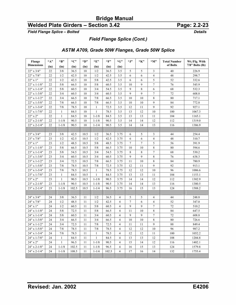
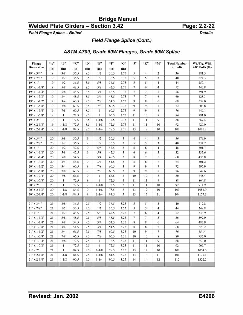
Bridge Manual Welded Plate Girders – Section 3.42 Page: 2.2-23 Field Flange Splice – Bolted Details
Revised: Jan. 2002 E4206
Field Flange Splice (Cont.)
ASTM A709, Grade 50W Flanges, Grade 50W Splice
Flange Dimensions
“A”
(in)
“B”
(in)
“C”
(in)
“D”
(in)
“E”
(in)
“F”
(in)
“G”
(in)
“J” “K” “M” Total Number of Bolts
Wt./Flg. With 7/8” Bolts (lb)
22" x 3/4" 22 3/8 36.5 10 1/2 36.5 3.5 5 5 3 40 226.9 22" x 7/8" 22 1/2 42.5 10 1/2 42.5 3.5 6 6 4 48 298.7 22" x 1" 22 1/2 42.5 10 5/8 42.5 3.5 6 6 5 52 332.6 22" x 1-1/8" 22 5/8 66.5 10 5/8 60.5 3.5 10 9 7 76 545.9 22" x 1-1/4" 22 5/8 60.5 10 3/4 54.5 3.5 9 8 6 68 532.3 22" x 1-3/8" 22 3/4 60.5 10 3/4 60.5 3.5 9 9 7 72 608.8 22" x 1-1/2" 22 3/4 66.5 10 7/8 66.5 3.5 10 10 8 80 717.1 22" x 1-5/8" 22 7/8 66.5 10 7/8 66.5 3.5 10 10 9 84 772.8 22" x 1-3/4" 22 7/8 78.5 10 1 72.5 3.5 12 11 9 92 927.1 22" x 1-7/8" 22 1 84.5 10 1 78.5 3.5 13 12 10 100 1067.3 22" x 2" 22 1 84.5 10 1-1/8 84.5 3.5 13 13 11 104 1165.1 22" x 2-1/8" 22 1-1/8 90.5 10 1-1/8 90.5 3.5 14 14 12 112 1319.0 22" x 2-1/4" 22 1-1/8 90.5 10 1-1/4 90.5 3.5 14 14 13 116 1386.9 23" x 3/4" 23 3/8 42.5 10.5 1/2 36.5 3.75 6 5 3 44 254.4 23" x 7/8" 23 1/2 42.5 10.5 1/2 42.5 3.75 6 6 4 48 310.7 23" x 1" 23 1/2 48.5 10.5 5/8 48.5 3.75 7 7 5 56 391.9 23" x 1-1/8" 23 5/8 66.5 10.5 5/8 66.5 3.75 10 10 8 80 594.6 23" x 1-1/4" 23 5/8 54.5 10.5 3/4 54.5 3.75 8 8 7 68 530.2 23" x 1-3/8" 23 3/4 60.5 10.5 3/4 60.5 3.75 9 9 8 76 638.3 23" x 1-1/2" 23 3/4 72.5 10.5 7/8 66.5 3.75 11 10 8 84 780.9 23" x 1-5/8" 23 7/8 78.5 10.5 7/8 72.5 3.75 12 11 9 92 913.1 23" x 1-3/4" 23 7/8 78.5 10.5 1 78.5 3.75 12 12 10 96 1006.6 23" x 1-7/8" 23 1 84.5 10.5 1 84.5 3.75 13 13 11 104 1153.1 23" x 2" 23 1 90.5 10.5 1-1/8 90.5 3.75 14 14 12 112 1302.9 23" x 2-1/8" 23 1-1/8 90.5 10.5 1-1/8 90.5 3.75 14 14 13 116 1380.5 23" x 2-1/4" 23 1-1/8 102.5 10.5 1-1/4 96.5 3.75 16 15 13 124 1588.2 24" x 3/4" 24 3/8 36.5 11 1/2 36.5 4 5 5 4 44 248.8 24" x 7/8" 24 1/2 48.5 11 1/2 42.5 4 7 6 4 52 347.0 24" x 1" 24 1/2 60.5 11 5/8 60.5 4 9 9 7 72 510.2 24" x 1-1/8" 24 5/8 72.5 11 5/8 66.5 4 11 10 8 84 647.5 24" x 1-1/4" 24 5/8 60.5 11 3/4 60.5 4 9 9 7 72 608.8 24" x 1-3/8" 24 3/4 66.5 11 3/4 66.5 4 10 10 8 80 726.6 24" x 1-1/2" 24 3/4 72.5 11 7/8 72.5 4 11 11 9 88 849.4 24" x 1-5/8" 24 7/8 78.5 11 7/8 78.5 4 12 12 10 96 987.2 24" x 1-3/4" 24 7/8 78.5 11 1 78.5 4 12 12 11 100 1052.2 24" x 1-7/8" 24 1 84.5 11 1 84.5 4 13 13 12 108 1204.8 24" x 2" 24 1 96.5 11 1-1/8 90.5 4 15 14 12 116 1402.1 24" x 2-1/8" 24 1-1/8 102.5 11 1-1/8 96.5 4 16 15 13 124 1579.8 24" x 2-1/4" 24 1-1/8 108.5 11 1-1/4 102.5 4 17 16 14 132 1755.4
Bridge Manual Welded Plate Girders – Section 3.42 Page: 2.3-1 Field Web Splice - Bolted Details
Revised: Jan. 2002 E4206
2.3 Field Web Splice - Bolted General Splices shall be designed using the Service Load Design Method and in accordance with AASHTO Articles 10.18, 10.24 and 10.32 except as noted. The web splice consists of 2-Plates: Thickness = 5/16" minimum.
Width = 12-1/2" (18-1/2" if 3 rows of bolts are required).
When the web section or steel grade changes at a splice, the smaller web strength should be used to design the splice.
Minimum Yield Strength (Fy) and Minimum Tensile Strength (Fu) ASTM A709 Grade 36 Fy = 36 ksi Fu = 58 ksi ASTM A709 Grade 50 Fy = 50 ksi Fu = 65 ksi ASTM A709 Grade 50W Fy = 50 ksi Fu = 70 ksi
Allowable Steel Stresses (Fb, Fv) Allowable stresses are determined from AASHTO Table 10.32.1A. Allowable bending stress Fb = 0.55 x Fy Allowable shear stress Fv = 0.33 x Fy ASTM A709 Grade 36 Fb = 20 ksi Fv = 12 ksi ASTM A709 Grade 50 Fb = 27 ksi Fv = 17 ksi ASTM A709 Grade 50W Fb = 27 ksi Fv = 17 ksi
Allowable Bolt Stresses Although standard holes are used in the fabrication of web splices, designing the splices for oversize holes allows for some fabrication and erection tolerances. Web splices required to resist shear between their connected parts are designated as slip-critical connections. Shear connections subjected to stress reversal, or where slippage would be undesirable, shall be slip-critical connections. Potential slip of joints should be investigated at intermediate load stages especially those joints located in composite regions. The resultant force shall be less than the allowable bolt shear force. All splice bolts shall be A325 7/8" diameter High Strength Bolts. Fv = 19 ksi
Bolt Arrangement The minimum distance from the center of any fastener in a standard hole to a sheared or thermally cut edge shall be 1-1/2 inches for 7/8" diameter fasteners. The minimum distance between centers of fasteners in standard holes shall be three times the diameter of the fastener, but shall not be less than 3 inches for 7/8" diameter fasteners.
Bridge Manual Welded Plate Girders – Section 3.42 Page: 2.3-2 Field Web Splice - Bolted Details
Revised: Jan. 2002 E4206
Splice Plate Strength The strength of the splice plates shall be determined by multiplying the allowable stress of the splice plates by the net area of all splice plates. The splice plates net area shall be taken as the gross area of the splice plates minus the bolt holes. Bolt holes are considered to be 1 inch diameter for the purpose of determining splice plate net area. Web splices are designed to develop 75% of net section of the web.
Web Strength
The strength of the web should be determined from the allowable web stress at the "top of web" to account for hybrid sections. Otherwise, the allowable web stress is based on a linear distribution of stress from outside face of flange to "top of web".
Weight of Splice
When calculating the weight of splice, the following simplified weights shall be used.
Weight of High-Strength bolts (diameter 7/8") = 0.95 lbs/bolt
Unit weight of Structural Steel = 490 lbs/ft3
Bridge Manual Welded Plate Girders – Section 3.42 Page: 2.3-3 Field Web Splice - Bolted Details
Revised: Jan. 2002 E4206
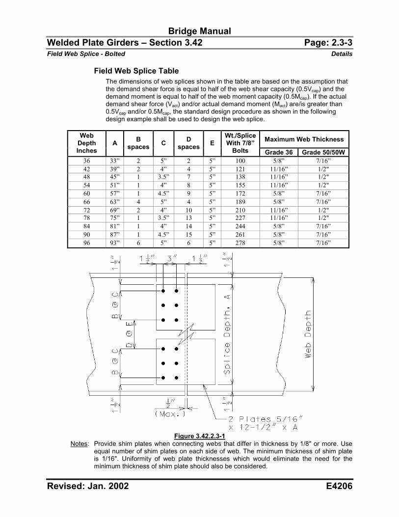
Field Web Splice Table The dimensions of web splices shown in the table are based on the assumption that the demand shear force is equal to half of the web shear capacity (0.5Vcap) and the demand moment is equal to half of the web moment capacity (0.5Mcap). If the actual demand shear force (Vact) and/or actual demand moment (Mact) are/is greater than 0.5Vcap and/or 0.5Mcap, the standard design procedure as shown in the following design example shall be used to design the web splice.
Maximum Web Thickness Web Depth Inches
A B spaces C D
spaces E Wt./Splice With 7/8”
Bolts Grade 36 Grade 50/50W36 33” 2 5” 2 5” 100 5/8” 7/16” 42 39” 2 4” 4 5” 121 11/16” 1/2" 48 45” 1 3.5” 7 5” 138 11/16” 1/2" 54 51” 1 4” 8 5” 155 11/16” 1/2" 60 57” 1 4.5” 9 5” 172 5/8” 7/16” 66 63” 4 5” 4 5” 189 5/8” 7/16” 72 69” 2 4” 10 5” 210 11/16” 1/2" 78 75” 1 3.5” 13 5” 227 11/16” 1/2" 84 81” 1 4” 14 5” 244 5/8” 7/16” 90 87” 1 4.5” 15 5” 261 5/8” 7/16” 96 93” 6 5” 6 5” 278 5/8” 7/16”
Figure 3.42.2.3-1
Notes: Provide shim plates when connecting webs that differ in thickness by 1/8" or more. Use equal number of shim plates on each side of web. The minimum thickness of shim plate is 1/16". Uniformity of web plate thicknesses which would eliminate the need for the minimum thickness of shim plate should also be considered.
Bridge Manual Welded Plate Girders – Section 3.42 Page: 2.3-4 Field Web Splice - Bolted Details
Revised: Jan. 2002 E4206
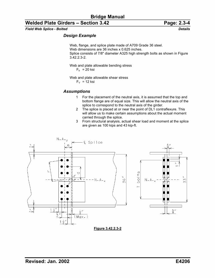
Design Example Web, flange, and splice plate made of A709 Grade 36 steel. Web dimensions are 36 inches x 0.625 inches. Splice consists of 7/8" diameter A325 high strength bolts as shown in Figure 3.42.2.3-2. Web and plate allowable bending stress Fb = 20 ksi Web and plate allowable shear stress FV = 12 ksi
Assumptions 1 For the placement of the neutral axis, it is assumed that the top and
bottom flange are of equal size. This will allow the neutral axis of the splice to correspond to the neutral axis of the girder.
2 The splice is placed at or near the point of DL1 contraflexure. This will allow us to make certain assumptions about the actual moment carried through the splice.
3 From structural analysis, actual shear load and moment at the splice are given as 100 kips and 43 kip-ft.
Figure 3.42.2.3-2
Bridge Manual Welded Plate Girders – Section 3.42 Page: 2.3-5 Field Web Splice - Bolted Details
Revised: Jan. 2002 E4206
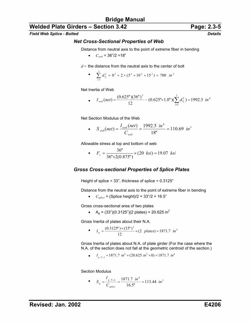
Net Cross-Sectional Properties of Web Distance from neutral axis to the point of extreme fiber in bending
�� Cweb = 36”/2 =18” d = the distance from the neutral axis to the center of bolt
�� 222227
1
2 700)15105(20 indi
Yi�������
�
Net Inertia of Web
��
47
1
23
5.1992))("0.1"625.0(12
)"36)("625.0()( indnetIi
Yweb i���� �
�
Net Section Modulus of the Web
��3
4
69.110"18
5.1992)()( inin
CnetInetS
web
webweb ���
Allowable stress at top and bottom of web
�� ksiksiFs 07.19)20()"875.0(2"36
"36��
�
�
Gross Cross-sectional Properties of Splice Plates
Height of splice = 33”, thickness of splice = 0.3125” Distance from the neutral axis to the point of extreme fiber in bending
�� Csplice = (Splice height)/2 = 33”/2 = 16.5”
Gross cross-sectional area of two plates �� Ag = (33”)(0.3125”)(2 plates) = 20.625 in2
Gross Inertia of plates about their N.A.
��4
3
7.1871)2(12
)"33()"3125.0( inplatesI g ��
�
�
Gross Inertia of plates about N.A. of plate girder (For the case where the N.A. of the section does not fall at the geometric centroid of the section.)
��424
.7.1871)0625.20(7.1871 inininI ANg ����
Section Modulus
��3
4.. 44.113
"5.167.1871 inin
C
IS
splice
ANgg ���
Bridge Manual Welded Plate Girders – Section 3.42 Page: 2.3-6 Field Web Splice - Bolted Details
Revised: Jan. 2002 E4206
Net Section Properties of Splice Plates Net area of two splice plates
�� An = 20.625 in2 – (1”)(0.3125”)(7 bolts)(2 plates) = 16.25 in2 Inertia loss due to the bolt holes in the plates
��422
7
1
5.437)700)("1)("625.0()( inindAiY
iHole ����
�
Net inertia of the splice plates
�� Isplice(net) = (1871.7 in4) – (437.5 in4) = 1434.2 in4 Net Section Modulus of Splice Plates
�� 34
92.86"5.16
2.1434)()( inin
CnetI
netSsplite
splicesplice ���
Web Capacity
Maximum Web Moment Capacity ��
)()(
netSFM webswebcap �� = (19.07 ksi) (110.69 in3) = 175.9 kip-ft Maximum Web Shear Capacity
�� )()( netAFV webVwebcap ��
= (12 ksi) (0.625”)(36”-7x1.0”) = 217.5 kips
)(100 GivenkipsVact � Based on AASHTO 10.18.1.1 the design value used for shear shall not be less than the average of the actual shear and the shear capacity of the section, and in no case less than 0.75 times the capacity of the section.
�� cap
capactDesign V
VVV 75.0
2��
�
���
� �
kipskipskipsVDesign 75.1582
)1005.217(�
��
or kipskipsVcap 1.163)5.217)(75.0()(75.0 ��� Use 163.1 kips
Eccentricity of shear load to centroid of bolt group
�� e = 1.5” + (0.5)(0.5”) + (0.5)(3”) = 3.25” Moment on splice induced by shear eccentricity
�� Me = Vact x e = (100 kips) x (3.25”) = 27.1 kip-ft
Bridge Manual Welded Plate Girders – Section 3.42 Page: 2.3-7 Field Web Splice - Bolted Details
Revised: Jan. 2002 E4206
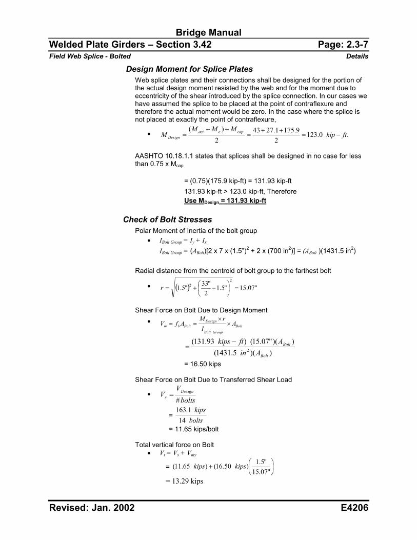
Design Moment for Splice Plates Web splice plates and their connections shall be designed for the portion of the actual design moment resisted by the web and for the moment due to eccentricity of the shear introduced by the splice connection. In our cases we have assumed the splice to be placed at the point of contraflexure and therefore the actual moment would be zero. In the case where the splice is not placed at exactly the point of contraflexure,
�� .0.1232
9.1751.27432
)(ftkip
MMMM capeact
Design ��
��
�
��
�
AASHTO 10.18.1.1 states that splices shall be designed in no case for less than 0.75 x Mcap = (0.75)(175.9 kip-ft) = 131.93 kip-ft 131.93 kip-ft > 123.0 kip-ft, Therefore Use M Design = 131.93 kip-ft
Check of Bolt Stresses Polar Moment of Inertia of the bolt group
�� IBolt Group = Iy + Ix IBolt Group = (ABolt)[2 x 7 x (1.5”)2 + 2 x (700 in2)] = (ABolt )(1431.5 in2)
Radial distance from the centroid of bolt group to the farthest bolt
�� � � "07.15"5.12
"33"5.12
2��
�
���
���r
Shear Force on Bolt Due to Design Moment
��Bolt
GroupBolt
DesignBoltbm A
IrM
AfV �
�
��
))(5.1431())("07.15()93.131(
2Bolt
Bolt
AinAftkips �
�
= 16.50 kips Shear Force on Bolt Due to Transferred Shear Load
��
boltsV
V Designs #�
= bolts
kips14
1.163
= 11.65 kips/bolt Total vertical force on Bolt
�� Vt = Vs + Vmy
= ��
���
��
"07.15"5.1)50.16()65.11( kipskips
= 13.29 kips
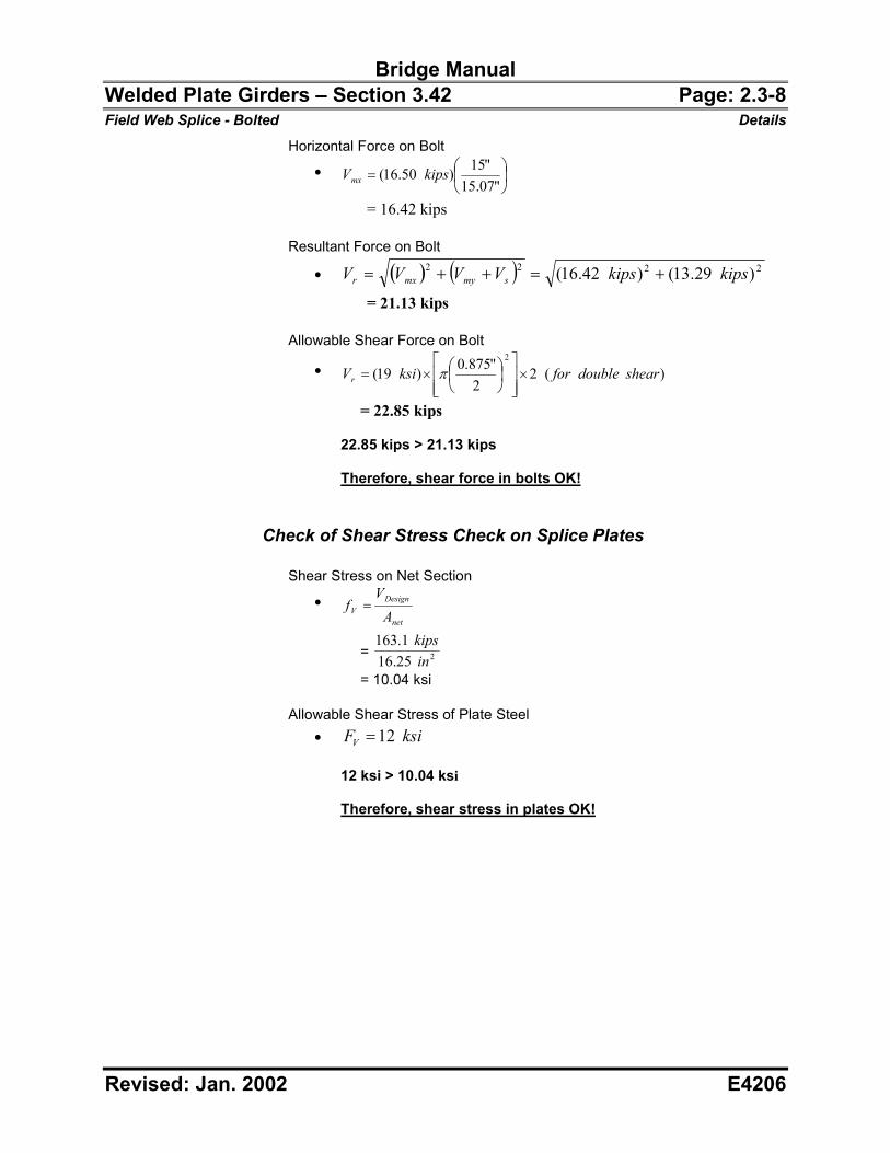
Bridge Manual Welded Plate Girders – Section 3.42 Page: 2.3-8 Field Web Splice - Bolted Details
Revised: Jan. 2002 E4206
Horizontal Force on Bolt
�� ��
���
��
"07.15"15)50.16( kipsVmx
= 16.42 kips Resultant Force on Bolt
�� � � � � 2222 )29.13()42.16( kipskipsVVVV smymxr �����
= 21.13 kips Allowable Shear Force on Bolt
�� )(22
"875.0)19(2
sheardoubleforksiVr ����
�
���
��
��
�� �
= 22.85 kips
22.85 kips > 21.13 kips Therefore, shear force in bolts OK!
Check of Shear Stress Check on Splice Plates Shear Stress on Net Section
��
net
DesignV A
Vf �
= 225.161.163
inkips
= 10.04 ksi Allowable Shear Stress of Plate Steel
�� ksiFV 12�
12 ksi > 10.04 ksi Therefore, shear stress in plates OK!
Bridge Manual Welded Plate Girders – Section 3.42 Page: 2.3-9 Field Web Splice - Bolted Details
Revised: Jan. 2002 E4206
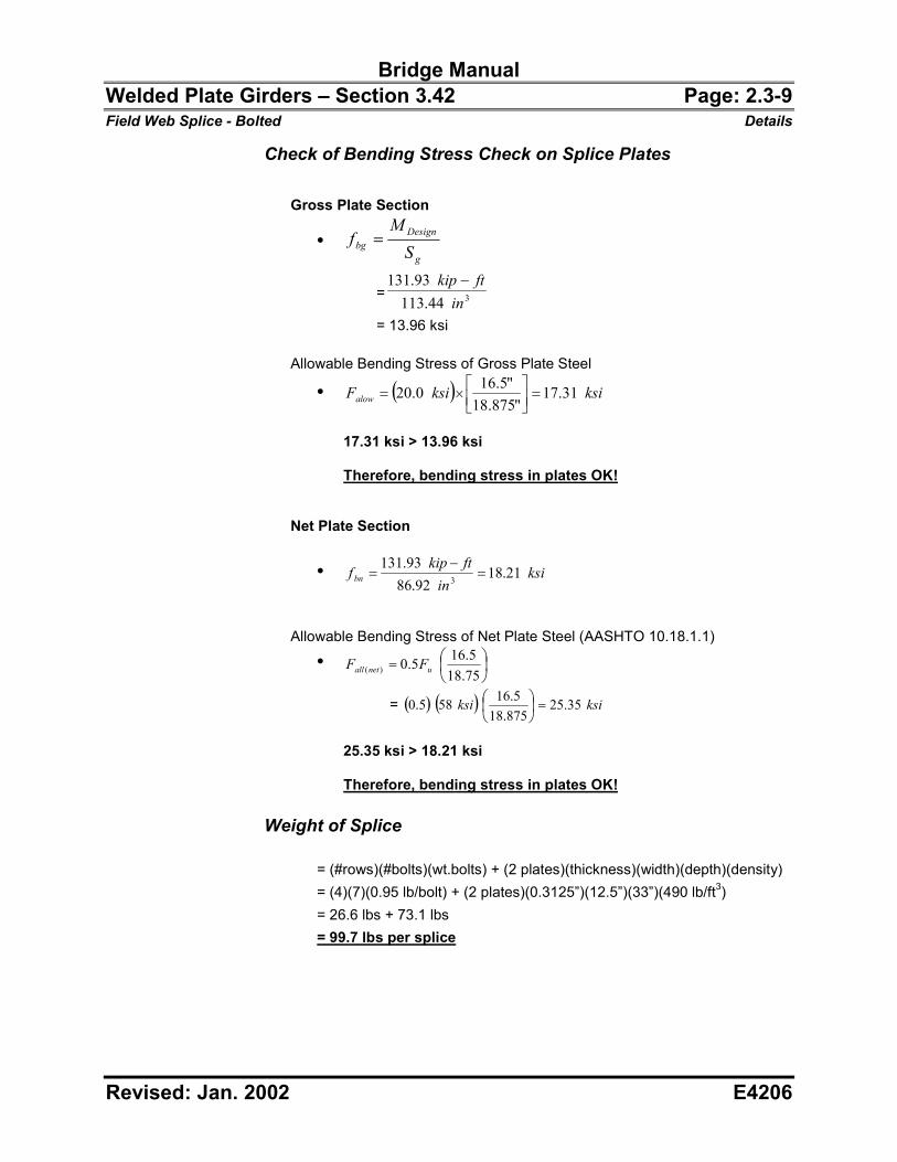
Check of Bending Stress Check on Splice Plates
Gross Plate Section
��
g
Designbg S
Mf �
= 344.11393.131
inftkip �
= 13.96 ksi Allowable Bending Stress of Gross Plate Steel
�� � � ksiksiFalow 31.17"875.18
"5.160.20 ���
���
���
17.31 ksi > 13.96 ksi Therefore, bending stress in plates OK!
Net Plate Section
�� ksiin
ftkipf bn 21.18
92.8693.131
3 �
�
�
Allowable Bending Stress of Net Plate Steel (AASHTO 10.18.1.1)
�� ��
���
��
75.185.165.0)( unetall FF
= � � � � ksiksi 35.25875.18
5.16585.0 ���
���
�
25.35 ksi > 18.21 ksi Therefore, bending stress in plates OK!
Weight of Splice
= (#rows)(#bolts)(wt.bolts) + (2 plates)(thickness)(width)(depth)(density) = (4)(7)(0.95 lb/bolt) + (2 plates)(0.3125”)(12.5”)(33”)(490 lb/ft3) = 26.6 lbs + 73.1 lbs
= 99.7 lbs per splice