Mission Overview - Utah State University
12
I I I I I I I I I I I I I I I I I I I mE NEAR SPACECRAFT TELECOMMUNICATIONS SYSTEM R. S. Bokulic, J. R. Jensen, T. R. McKnight The Johns Hopkins University Applied Physics Laboratory Laurel, Maryland Abstract The Near Earth Asteroid Rendezvous (NEAR) mission, frrst in NASA's Discovery series, is designed to gather scientific data about the near-Earth asteroid 433 Eros. Due to launch in February 1996, the spacecraft will rendezvous with and eventually orbit the asteroid. The telecommunications system is centered about tWo redundant X-band transponder systems that provide the command, telemetry, and tracking functions. Although the mission has a very tight development schedule, a significant amount of new technology has been used in the telecommunications system. Included in the design are the most recent developments in transponder hardware, an X-band solid state power amplifier (a deep space "first"), and several microstrip patch antennas. During spacecraft emergencies, a microstrip array antenna becomes an integral part of a unique acquisition algorithm used to frnd the earth, similar to a search radar concept. To complement the flight hardware development, a comprehensive set of RF ground support equipment (RF GSE) has been developed. Also discussed are areas for potential technology improvements for future missions. Introduction The launch of the Near Earth Asteroid Rendezvous (NEAR) spacecraft in February 1996 will be the frrst in NASA's series of Discovery-class missions. These missions are intended to provide frequent access to space using relatively low-cost spacecraft with limited, well-defined science objectives. The NEAR spacecraft will rendezvous with and eventually go into orbit about the near-Earth asteroid Eros 433, studying it for a period of about one year during 1999. To achieve a balance between weight, power, performance, and cost, the design of the telecommunications system makes extensive use of new technology. At the heart of the system are redundant X-band transponders, recently developed by Motorola under sponsorship from the Jet Propulsion Laboratory (JPL) for the Cassini program. The downlink signal is amplified by a 5-watt solid state power amplifier (SSPA) developed by JHU/APL. The use of solid state X-band power amplification is a frrst for a deep space mission, breaking with the traditional traveling wave tube (TWT) approach. The downlink data is interfaced to the transponder by a lightweight telemetry conditioning unit (TCU) being developed by JHU/APL for NEAR. The data return from the asteroid will be enhanced through the use of rate 1/6, k=15 convolutional coding. The uplink data is detected by a new command detector unit (CDU), recently developed by JPL for the Cassini program. A complement of three antenna types are used for communications. The primary communication link is provided by a composites-based high gain antenna (HGA). Communications during certain portions of the miSSion, including sun-safe mode, are accomplished with a medium-gain fanbeam antenna and a low-gain antenna (LGA), both of which incorporate patch antenna technology. A novel method of regaining earth communications using the fanbeam antenna is incorporated into the sun-safe mode design. Mission Overview ... After launch aboard a 7925 Delta II vehicle, NEAR will cruise for a period of three years, including a deep space bum in July 1997 and an earth swingby in January 1998, until it reaches the Eros asteroid in January 1999. The spacecraft is designed for simplicity by configuring the HGA and solar panels so that they are fix-mounted and pointed along the same
Transcript of Mission Overview - Utah State University

I I I I I I I I I I I I I I I I I I I
mE NEAR SPACECRAFT TELECOMMUNICATIONS SYSTEM
R. S. Bokulic, J. R. Jensen, T. R. McKnight
The Johns Hopkins University Applied Physics Laboratory
Laurel, Maryland
Abstract
The Near Earth Asteroid Rendezvous (NEAR) mission, frrst in NASA's Discovery series, is designed to gather scientific data about the near-Earth asteroid 433 Eros. Due to launch in February 1996, the spacecraft will rendezvous with and eventually orbit the asteroid. The telecommunications system is centered about tWo redundant X-band transponder systems that provide the command, telemetry, and tracking functions. Although the mission has a very tight development schedule, a significant amount of new technology has been used in the telecommunications system. Included in the design are the most recent developments in transponder hardware, an X-band solid state power amplifier (a deep space "first"), and several microstrip patch antennas. During spacecraft emergencies, a microstrip array antenna becomes an integral part of a unique acquisition algorithm used to frnd the earth, similar to a search radar concept. To complement the flight hardware development, a comprehensive set of RF ground support equipment (RF GSE) has been developed. Also discussed are areas for potential technology improvements for future missions.
Introduction
The launch of the Near Earth Asteroid Rendezvous (NEAR) spacecraft in February 1996 will be the frrst in NASA's series of Discovery-class missions. These missions are intended to provide frequent access to space using relatively low-cost spacecraft with limited, well-defined science objectives. The NEAR spacecraft will rendezvous with and eventually go into orbit about the near-Earth asteroid Eros 433, studying it for a period of about one year during 1999.
To achieve a balance between weight, power, performance, and cost, the design of the
telecommunications system makes extensive use of new technology. At the heart of the system are redundant X-band transponders, recently developed by Motorola under sponsorship from the Jet Propulsion Laboratory (JPL) for the Cassini program. The downlink signal is amplified by a 5-watt solid state power amplifier (SSPA) developed by JHU/APL. The use of solid state X-band power amplification is a frrst for a deep space mission, breaking with the traditional traveling wave tube (TWT) approach. The downlink data is interfaced to the transponder by a lightweight telemetry conditioning unit (TCU) being developed by JHU/APL for NEAR. The data return from the asteroid will be enhanced through the use of rate 1/6, k=15 convolutional coding. The uplink data is detected by a new command detector unit (CDU), recently developed by JPL for the Cassini program.
A complement of three antenna types are used for communications. The primary communication link is provided by a composites-based high gain antenna (HGA). Communications during certain portions of the miSSion, including sun-safe mode, are accomplished with a medium-gain fanbeam antenna and a low-gain antenna (LGA), both of which incorporate patch antenna technology. A novel method of regaining earth communications using the fanbeam antenna is incorporated into the sun-safe mode design.
Mission Overview
... After launch aboard a 7925 Delta II
vehicle, NEAR will cruise for a period of three years, including a deep space bum in July 1997 and an earth swingby in January 1998, until it reaches the Eros asteroid in January 1999. The spacecraft is designed for simplicity by configuring the HGA and solar panels so that they are fix-mounted and pointed along the same

axis. This configuration is made possible by the mission trajectory design, which keeps the sunprobe-earth (SPE) angle within 400 over the majority of the mission (Fig. 1). Except for portions of the mission when the spacecraft is near the earth, the HGA can always be pointed toward the earth with only a modest reduction in solar array power. The earth-spacecraft range varies widely, with a maximum at 3.2 AU.
The NEAR telecommunications system must simultaneously satisfy the conflicting goals of low weight, low power, low cost, and an extremely short delivery schedule (26 months from funded start to launch). The prime requirement is to provide adequate science return during the asteroid portion of the mission. This translates to a data return of at least 85 megabits per day, with a strong desire to maximize the return as much as possible. The telecommunications system must also provide a command link and high quality Doppler information for vehicle tracking. The deep space network (DSN) 34-meter high efficiency and beam waveguide antennas will be use for all phases of the mission except critical periods and
3 I I I , , I ,
. I ,
........ 2 . ! I , ,
• CII · C) · c: cu · 0:: I
I
.c: I
t::: cu UJ
, , , , , , I , , . , ",
· · · I
i ~
" " I' ' ' I I , . I
, , I , ,
I , , . I . , . ,
emergencies, during which the 70-meter dishes will used.
Telecommunications System Design
Figure 2 shows the block diagram of the NEAR telecommunications system. The X-band frequency region (7.2/8.4 GHz) was chosen to maximize the data rate and tracking capabilities and to minimize the size of the HGA feed. Redundant, state-of-the-art Motorola transponders are at the heart of the system. These units were developed under sponsorship from JPL for the Cassini program and will be flown for the first time on NEAR. They have been modified for the NEAR application to provide a wider bus voltage range (22 to 34 VDC), different RF frequencies, and a coaxial receiver input instead of waveguide. The telemetry conditioning unit (TCU) was developed by JHU/ APL. It sets the downlink mode (normal or sun-safe) and fixes the modulation index in each mode. Normal mode data is directly modulated on the carrier while sun-safe mode data is first modulated onto a 22.5 kHz subcarrier. The TCU incorporates most of its digital functions on a field-
100
90
80
70 ........ en
60 CII 0 -, Earth Range 50 CII
SPEAngle "5 .a: 40 UJ a.
.;; 30 en .. , . ; , ; 20 . , . , , , ,
I , I 10 ,
I , , , .' 0
o L-L-____ ~ ________________________ ~ ________ ~~ ________ ~ ________ ~ ____________ ~ ________ ~
1996 1997 1998 1999 2000
Year
Figure 1. Earth range and Sun-Probe-Earth (SPE) angle for the NEAR mission
2
I I I I I I I I I I I I I I I I I I I

I I I I I I I I I I I I I I I I I I I
programmable gate array. The downlink: signal is amplified to a 5-watt level by an SSPA developed by JHU/APL. This represents the first use of solid state power devices for X-band amplification on a deep space mission. The uplink: data is demodulated by a command detector unit (CDU) developed by JPL. This unit incorporates all of the synchronization and detection functions onto a single application specific integrated circuit (ASIC) chip.
To save weight and mmlImze mechanical complexity, coaxial cabling was chosen instead of waveguide. Initially there was concern over the RF losses associated with such an approach; however, the use of 0.29-inch diameter cabling kept the loss between the power amplifier and HOA feed to 2 dB including cabling, switches, and diplexers.
To minimize weight, the HOA reflector is constructed with a graphite-resin material on a Nomex honeycomb core. The diameter is 1.5 meters. The feed is a choke ring hom with a septum polarizer. The downlink gain is 40 dBic. Co-located on the feed assembly are a low gain antenna (LOA) and magnetometer. The presence of the magnetometer required careful
X-BAND DEEP SPACE
TRANSPONDER .1
X·BAND DEEP SPACE
TRANSPONDER .2
selection of materials for the feed assembly, including non-magnetic RF connectors made with beryllium copper.
To provide antenna coverage during portions of the mission when the SPE angle is too large to use the high gain antenna, two additional antenna designs were developed. The low gain antenna provides hemispherical coverage in the forward and aft directions for portions of the mission when the spacecraft is relatively close to the earth. This antenna is an extremely lightweight (90 grams) dual-frequency microstrip patch that provides a peak gain of about 6 dBic (Fig. 3). The fanbeam antenna is a dual-frequency microstrip array that provides coverage during cruise phase, earth swingby phase, and sun-safe mode recovery (Fig. 4). The series-fed element technique used for the fanbeam provides for an efficient design, with a peak downlink gain of 18.8 dBic. The antenna provides wide-plane coverage to 40° from the spacecraft Z-axis with a narrow-plane 3 dB beamwidth of 8°. It weighs 465 grams. Figure 5 depicts the coverage patterns of all the NEAR antennas. Shown in Table 1 is a breakdown of the power and weight of the NEAR telecommunications system.
.~
FAN BEAM ANTENNA
BWaBox4()O
HIGH GAIN ANTENNA 1.5m DISH
Switches shown In launch configuration
. Figure 2. Block Diagram of the NEAR Spacecraft Telecommunications System
3

Figure 3. The NEAR low gain antenna. The antenna incorporates two dual-frequency stacked patches, one for ~ach polarization. Courtesy of designer Allan Jablon.
Figure 4. The NEAR fanbeam antenna. The series-fed elements provide for improved efficiency over corporate-fed elements. The uplink and downlink portions are combined with a microstrip diplexer. Courtesy of designer Jeffrey Sinsky.
4
I I I I I I I I I I I I I I I I I I I

I I I I I I I I I I I I I I I I I I I
Table 1. Power and weight breakdown. Values are per unit unless otherwise noted.
Item Nominal Bus Weight Power (W)
X-Band Transponder Exciter 2.5
Receiver 6.6 Cmd. Detector Unit 1.0
Tim. Conditioning Unit 3.0 Solid State Pwr. Amplifier 34
Pwr. Converter for SSPA 0 Diplexer 0 Coaxial Switch Assembly 0 High Gain Antenna 0 Fanbeam Antenna 0 Lowgain Antenna 0
Z-AXIS HIGH GAIN ANTENNA :!:1' ABOUT NADIR
FANBEAM ANTENNA COVERAGE TO 400 FROM NADIR
Figure 5. NEAR spacecraft antenna coverage.
Data Rate Capability
To keep the system design simple, the selection of uplink and downlink data rates is limited. Two uplink data rates are used: 125 bps for nonnal operations and 7.8 bps for emergency operations. Eight downlink data rates are used. Six of the rates are between 1.1 and 26.5 kbps and are used for nonnal downlink operations. The remaining two rates are 39.4 and 9.9 bps and are used for sun-safe mode
(kg) 4.0
0.36
0.83 0.8
1.26 0.1 0.64 6.3
0.47 0.1
5
Notes
Includes 79% efficient power converter in transponder
Includes 80% efficient external power converter
Includes all five switches. Excluding magnetometer & LGA
recovery and some cruise operations. Once the spacecraft reaches the asteroid, the downlink data rate will vary from 4.4 to 8.8 kbps, depending on the desired link margin and the mission time (the asteroid moves closer to the earth as time progresses). Occasional use of the 70-meter dishes will pennit data dumping at 17.6 and 26.5 kbps. Two convolutional codes are incorporated on NEAR: a rate 112, k=7 code for cruise and sun-safe operations and a rate 116, k= 15 code for asteroid operations. In all cases, the data is concatenated with a Reed-Solomon 8-bit (255,223) block code. Figure 6 shows the downlink data rate capability during asteroid operations. The NEAR telecommunications system design assumes the use of Block V receivers in the DSN.
30
Arrival + 1 year
................... 1!,~.~PJ?~\ 1 dSMargin
:2 dB Margin
:I daMargm
o~~~==~====~======~-1999.0 1999.5 2000.0
Year
Figure 6. NEAR downlink data rate capability at the asteroid assuming use of the rate 116, k=15 convolutional code and a 34-meter ground antenna. Weather=90%. Ground elevation angle; 20°.

Sun-Safe Mode Recovery
Overview
One of the more c!1alIenging aspects of the telecommunications system design is the recovery of the spacecraft under emergency conditions. In the event of a serious anomaly such as low bus voltage, the spacecraft is autonomously pointed at the sun and begins a 2°/minute about the spacecraft-sun axis (the Zaxis) until contact with the earth is made. Because of the relatively large distances involved (up to 3.2 AU) and the relatively low transmitter power, a medium gain antenna is required to establish earth communications. The fanbeam antenna provides a radiation pattern that extends from the Z-axis to approximately 40° off of the Z-axis. As the spacecraft rotates, the emitted signal will eventually sweep through the earth direction and be detectable· on the ground. With knowledge of the rotation rate, ground controllers can then send a "stop rotation" command one revolution later. When the spacecraft roll is stopped, the downlink is modulated with low-rate data (39.4 or 9.9 bps) and troubleshooting can commence. For portions of the mission when the SPE angle is greater than 40°, the earth range is sufficiently low that commanding can be done through the forward low gain antenna regardless of rotation phase.
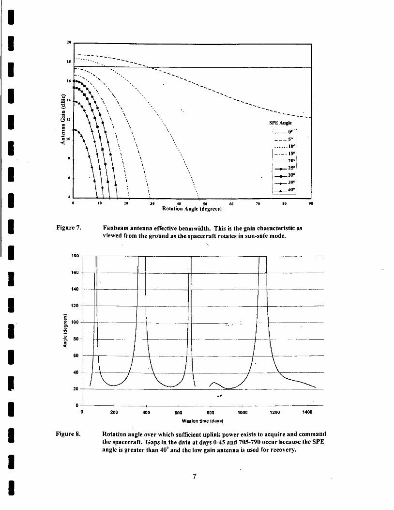
Fanbeam Effective Radiation Pattern
The fanbeam antenna provides a dualfrequency radiation pattern with a narrow-plane 3 dB beamwidth of about So. In the sun-safe scenario, it is tempting to assume that the antenna provides appreciable gain over only SO of spacecraft rotation; however, detailed consideration of the geometry shows that the situation is very much better than that. For example, at the greatest distances from earth, the SPE angle is close to zero and the antenna gain is essentially constant over the entire spacecraft rotation. As the SPE angle increases, the antenna gain will vary more over a rotation; however, the 3dB beamwidth as viewed from the
6
ground is much greater than the beamwidth of the antenna itself (Fig. 7). This effect extends the time within which sufficient antenna gain exists for recovery from sun-safe mode.
Timing Considerations
Based upon the NEAR link analysis and an uplink receiver threshold of -135 dBm*, Figure S shows the rotation angle over which sufficient gain is present for command reception during the course of the mission. The worst-case rotation angle is about 21 degrees. At a rotation rate of 2°/minute, this sector is swept through in 10.5 minutes. Shown in Figure 9 is the planned uplink acquisition and command scenario. Given a spacecraft receiver best lock frequency uncertainty of 8 kHz, the time required to lock the receiver and send a "stop rotation" command to both command systems is 3.7 minutes, providing a margin of 6.S minutes. Of course, the phase of the spacecraft rotation must be inferred from the ground accurately enough to time the uplink command transmission properly.
Inferring the phase of the spacecraft rotation must be done from observation of the downlink beacon. Given a spacecraft rotation rate of 2°/minute, Figure 10 shows the halfpower width of the downlink beacon in seconds as viewed from the ground over the duration of the mission. The half-power width varies over the mission due to variations in the SPE angle. The worst-case is about 6.5 minutes of observation time. Based upon previous discussion, it is evident that the timing margin is sufficient to permit the uplink acquisition sequence to be centered anywhere within the 3-dB beam width of the observed downlink signaL
*This is a conservative threshold for carrier acquisition at a 200 Hz/sec sweep rate.
..
I I I I I I I I I I I I I I
II I I I I
I I I I I I I I I I I I I I I I I I I
10.-______________________________________________ ----______________ ~
--------............. ---18 ...... - __
, 16
8
" , , \
\
\
\
\
\
\
\
--
\
\
\
\
\
\
SPEAngle
1_°·' . ___ 5· i
• .••••. IO·!
_._.ISO.
_ .. _10"1' _25· _30": __ 3S.! ._40".
4L-__ ~~~~ __ ~--__ --~ __ ----------~==~~ o
Figure 7.
180
160
140
120
i 100 I!!
01 <lI i :s. ~ 80 01 I: «
60
40
I 20
0 o
Figure 8.
10
\
10 30 40 50 60 70 110 Rotation Angle (degrees)
Fanbeam antenna effective beamwidth. This is the gain characteristic as viewed from the ground as the spacecraft rotates in sun-safe mode.
i:.,. :
\ I \ / \ I /' \
90
...
"--./ ~ ~L ~ .'
200 400 600 800 1000 1200 1400
Mission time (days)
Rotation angle over which sufficient uplink power exists to acquire and command the spacecraft. Gaps in the data at days 0-45 and 705-790 occur because the SPE angle is greater than 40° and the low gain antenna is used for recovery.
7

Frequency
Subcarrier u. switch-on "Stop rotation" command Satellite CIl
to both command processors deceleration Cl delay t:
!!! >. u t: CIl 176 bits CDU acquisition
3 hour period :::J 'or each command processor: 0-
~ 25 urad/s 2ciecel. u. 16 bits start sequence
128 bits command 0.4 degree travel
64 bits tail sequence
I" ~I- -I- -I- ~I 60seconds 60 seconds 75.8 seconds (F=8 kHz) (592 bits at 7.8125 bps)
23.2 seconds
1--219 seconds
-I
Figure 9. DSN uplink command scenario
1000
900 +- 1-' ....
800
;n 700 "1:1 C 0 <> ... 600 $ :; "1:1
"i soo m "1:1 M ... 400 .5
I \ ~ _ ......
\ \
I \ I \ \ / \ I / ~ V V f""-.. J ~
I -1 300 c
200
100
0+--------+--------+--------+--------+--------+--------+--------+----o
Figure 10.
200 400 600 SOO 1000 1200 1400
Mission time (days)
Duration of downlink beacon half power beamwidth as a function of mission time. Gaps in the data at days 0-45 and 705-790 occur because the SPE angle is greater than 40° and the low gain antenna is used for recovery.
8
I I I
I I I I I I I I I I I I I I I

I I I I I I I I I I I I I I I I I I I
RF Ground Support Equipment
The design goal for the RF ground support equipment (RF GSE) was to provide a capable, cost effective way to test the RF telecommunications system during subsystem integration and to provide RF communications to the spacecraft during spacecraft integration aI'\d test activities. A significant challenge of the design was to provide equipment capable of receiving deep space signaling formats without incurring prohibitive costs. The resulting design is a combination of off-the-shelf and special purpose equipment with technical.innovations in several key areas.
Figure 11 shows a block diagram of the RF GSE. The system emulates the NEAR spacecraft Command and Telemetry Processor to provide test and control signals for subsystemlevel testing. Functions include convolutional coding (rate 112, k=7 and rate 1/6, k=l5), ReedSolomon coding, and CCSDS* framing of the downlink data. Also included are control and telemetry interfaces for the transponder, CDU and TCU. The RF GSE provides uplink and downlink RF interfaces to the subsystem. A split-channel receiver system, developed by Microdyne for NEAR, provides superior carrier threshold performance in comparison with
X-Band Downlink From Spacecraft
Integration & TestGSE
Ethernet Control Computer (Power Macintosh with LabView 3)
Uplink Commands
Digital Control
I---VME Bus
GPIB
traditional telemetry receiver designs. Additionally, the RF GSE provides the capability to decode the rate 116, k=l5 convolutional coding employed by NEAR. The decoder design, which was realized on a single VME 6U card, performs code inversion at high signal levels by synchronizing to the encoded CCSDS frame sync word and inverting the code generator polynomial * * . This innovation is significant because traditional Maximal Likelihood Decoding for such a long constraint length is complicated, and the only device that performs this functio!l is still in development by JPL. The RF GSE also provides Reed-Solomon decoding, thus allowing bit error, rate measurements of the concatenated coded downlink data.
The RF GSE has the capability to be fully automated. Most functions are under the control of a Power Macintosh with Lab View 3 software. It accepts configuratipn commands and provides status and test results over an Ethernet interface to the spacecraft-level integration and test GSE.
*Consultative Committee for Space Data Systems.
**Developed by Mark Simpson of JHU/APL.
RF Downlink Equipment
~ Demodulated Downlink
Decoded Digital Telemetry ~
Digital Commands Baseband
" Equipment to RFsystem , Telemetry Monitor P
{\ ~ Uplink Digital Data
from RF system
RF Uplink X-Band Uplink To Spacecraft .liiqulpment
Figure 11. Simplified block diagram ofthe NEAR RF Ground Support Equipment
9
Integration & TestGSE
olnts

Future Technology Development Areas
Development of the NEAR telecommunications system has revealed several areas where technology advancements can significantly improve the performance of the deep space mission. First, there is clearly room for substantial integration of the transpond~
system. Future transponder designs should incorporate the TCU and CDU functions into the transponder and provide further miniaturization through the use of monolithic microwave integrated circuits (MMICs) and applicationspecific integrated circuits (ASICs). In addition, the use of non-coherent transponders in conjunction with an ultra-stable oscillator have the potential for providing substantial reductions in weight.
Second, there is clearly room for improvements in solid state power amplifier. efficiency. The efficiency of X-band SSPAs using present-day GaAs FET technology is typically 15-25%. This can be improved substantially by developing technologies such as heterojunction bipolar transistors (HBTs). Amplifiers incorporating such technologies are being developed at JHU/ APL at the present time. Figure 12 shows a 4-watt X-band HBT amplifier design currently under development. Efficiency improvements using HBT technology have the
10
potential for doubling the science return of future missions.
Another future technology area is K.band transmitter equipment. By moving the downlink ,frequency from X to K.-band (32 GHz), the science return from a given mission can be increased by a factor 00 to 5.
Finally, . NEAR has shown that microstrip antenna technology provides a lightweight, low-cost alternative to conventional antennas. Now that it is developed, the NEAR fanbeam antenna can be reproduced at extremely low cost and in a short time frame (2-3 months including flight qualification). The design can also be easily scaled to other frequencies such as S and K.-band. This technology can be further improved by such advances as dual frequency elements and aperture feeding.
Acknowledgments
The NEAR program is sponsored by the 'NASA Office of Space Science. Many thanks go to all of the people ofthe Microwave and RF Systems Group (S2R) who worked so hard to design and implement the telecommunications system in such a short timeframe.
I I I I I I I I I I I I I I I I I I I

I I I I I I I I I Figure 12.
I I I I I I I I I I
X-Band HBT .Pow~r Amplifier
A 4-watt, X-Band heterojunction bipolar transistor (HBT) power amplifier under development at JHU/APL. Courtesy of designer Matt Reinhart.
. ~
11
THE NEAR SPACECRAFT TELECOMMUNICATIONS SYSTEM
Author Bio"raphies
Robert S. Bokulic \..
Robert Bokulic has been employed in the Space Department at the 10hns Hopkins University Applied Physics Laboratory (JHU/APL) since 1982. He received his BSEE from Virginia Polytechnic Institute in 1982 and his MSEE from 10hns Hopkins ' University in 1985. During his employment at JHU/APL, he has specialized in SPlJC~cr.p.ft communications system design and RF !Microwave component design. He was ,. responsible for communications hardware on the Delta 180,181,183 spacecraft series and the Midcolll'se Space Experiment (MSX). He is currently the lead. engineer for the NEAR telecommunications system.
J. Robert Jensen
Robert 1ensenjoined APL,in 1978 after receiving a bachelors degree from Cornell College in Mt. Vernon, Iowa and a PhD from the University of Wisconsin, Madison. He has been a member of the Space Department at JHU/APL since 1989. His work at JHUI APL has been chiefly concerned with the d~sign and analysis of radar systems for imaging and measurement of the ocean surface. Recently this has included the Topex and Geosat Follow-on radar altimeters and new system designs for ice altimetry and scatterometry .
Thomas R. McKnj"ht
Tom McKnight received a B.S. in electrical engineering from the University of Maryland in 1985 and an M.S. in electrical engineering in 1989 from the 10hns Hopkins University. He began his career at APL in 1985 as a design engineer developing Global Positioning System receiver hardware and software. More recently, Mr. McKnight has been the lead test and verification engineer for the NEAR telecommunications system. He has also been responsible for the development of hardware, spftware and algorithms for an S-Band monopulse radar on the Midcourse Space Experiment (MSX). Prior to this, he developed signal processing algorithms for the detection of speech in noise, and for the analysis of laser radar vibration sensor signal returns.
I I I I I I I I I I I I I I I I I I I