Mission Concept StudyMission Concept Study G 09_Mars-Sample-Return... · Mission Concept...
43
Mission Concept Study Mission Concept Study National Aeronautics and Space Administration www.nasa.gov Planetary Science Decadal Survey MSR Lander Mission Science Champion: Phil Christensen ([email protected]) NASA HQ POC: Lisa May ([email protected]) April 2010 Planetary Science Decadal Survey MSR Lander Mission Science Champion: Phil Christensen ([email protected]) NASA HQ POC: Lisa May ([email protected]) April 2010
-
Upload
duongnguyet -
Category
Documents
-
view
221 -
download
0
Transcript of Mission Concept StudyMission Concept Study G 09_Mars-Sample-Return... · Mission Concept...

Mission Concept Study Mission Concept Study
National Aeronautics and Space Administration
www.nasa.gov
Planetary Science Decadal Survey
MSR Lander Mission
Science Champion: Phil Christensen ([email protected]) NASA HQ POC: Lisa May ([email protected])
April 2010
Planetary Science Decadal Survey
MSR Lander Mission
Science Champion: Phil Christensen ([email protected]) NASA HQ POC: Lisa May ([email protected])
April 2010

MSR Lander Mission i
Data Release, Distribution, and Cost Interpretation Statements This document is intended to support the SS2012 Planetary Science Decadal Survey.
The data contained in this document may not be modified in any way.
Cost estimates described or summarized in this document were generated as part of a preliminary concept study, are model-based, assume a JPL in-house build, and do not constitute a commitment on the part of JPL or Caltech. References to work months, work years, or FTEs generally combine multiple staff grades and experience levels.
Cost reserves for development and operations were included as prescribed by the NASA ground rules for the Planetary Science Decadal Survey. Unadjusted estimate totals and cost reserve allocations would be revised as needed in future more-detailed studies as appropriate for the specific cost-risks for a given mission concept.

MSR Lander Mission i
Planetary Science Decadal Survey Mission Concept Study Final Report
Acknowledgments ........................................................................................................ iv
Executive Summary ...................................................................................................... v
Mission Concept ........................................................................................................................... v
Key Technologies and Risks ......................................................................................................... v
1. Scientific Objectives ............................................................................................ 1
Science Questions and Objectives ............................................................................................... 1
Science Traceability ...................................................................................................................... 1
2. High-Level Mission Concept ............................................................................... 2
Overview ....................................................................................................................................... 2
Concept Maturity Level ................................................................................................................. 2
Technology Maturity ...................................................................................................................... 3
Key Trades .................................................................................................................................... 3
3. Technical Overview .............................................................................................. 5
Instrument Payload Description .................................................................................................... 5
Flight System ................................................................................................................................ 5
Concept of Operations and Mission Design ................................................................................ 17
Planetary Protection .................................................................................................................... 19
Risk List ...................................................................................................................................... 19
4. Development Schedule and Schedule Constraints ......................................... 22
High-Level Mission Schedule ...................................................................................................... 22
Technology Development Plan ................................................................................................... 22
Development Schedule and Constraints ..................................................................................... 23
5. Mission Life-Cycle Cost ..................................................................................... 24
Costing Methodology and Basis of Estimate .............................................................................. 24
Cost Estimates ............................................................................................................................ 24

MSR Lander Mission ii
Figures Figure 3-1. Proposed MSR Lander CEDL System ....................................................................................... 5
Figure 3-2. Cruise Stage Concept (Inherited from MSL) .............................................................................. 6
Figure 3-3. Entry System Concept (Inherited from MSL) .............................................................................. 8
Figure 3-4. Proposed Descent Stage (Inherited from MSL) ......................................................................... 9
Figure 3-5. Proposed Lander Concept ........................................................................................................ 11
Figure 3-6. Two-Stage Solid Motor MAV Concept, in Proposed Launch Configuration ............................. 13
Figure 3-7. Fetch Rover Concept in Relation to MER ................................................................................ 16
Figure 3-8. Representative Lander Mission Timeline in Relation to the Orbiter Mission ............................ 18
Figure 3-9. 5 x 5 Risk Matrix ....................................................................................................................... 20
Figure 4-1. Development Schedule for the Proposed Lander Mission ....................................................... 22
Tables Table 2-1. Concept Maturity Level Definitions .............................................................................................. 3
Table 3-1. Cruise Stage Mass and Power Preliminary Estimates ................................................................ 6
Table 3-2. Proposed Cruise Stage Characteristics ....................................................................................... 7
Table 3-3. Entry Stage Mass and Power Preliminary Estimates .................................................................. 8
Table 3-4. Proposed Entry System Characteristics ...................................................................................... 8
Table 3-5. Descent Stage Mass and Power Preliminary Estimates ............................................................. 9
Table 3-6. Proposed Descent Stage Characteristcs ..................................................................................... 9
Table 3-7. Lander Mass and Power Preliminary Estimates ........................................................................ 11
Table 3-8. Proposed Lander Characteristics .............................................................................................. 12
Table 3-9. MAV Mass and Power Preliminary Estimates ........................................................................... 14
Table 3-10. MAV Concept Characteristics .................................................................................................. 14
Table 3-11. Fetch Rover Mass and Power Preliminary Estimates ............................................................. 16
Table 3-12. Proposed Fetch Rover Characteristics .................................................................................... 16
Table 3-13. Mission Design Concept .......................................................................................................... 18
Table 3-14. Mission Operations and Ground Data Systems ...................................................................... 19
Table 3-15. Top Risks for the Proposed Lander Mission ............................................................................ 19
Table 3-16. Risk Level Definitions .............................................................................................................. 21
Table 4-1. Proposed Key Phase Duration .................................................................................................. 22
Table 5-1. Total Estimated Mission Cost Funding Profile ........................................................................... 25

MSR Lander Mission iii
Appendices
A. Acronyms
B. References
C. Lander Mission Master Equipment Lists from Team X Study
MSR Lander Mission iv
Acknowledgments This report was authored by Richard Mattingly, Jet Propulsion Laboratory, California Institute of Technology.
This research was carried out at the Jet Propulsion Laboratory, California Institute of Technology, under a contract with the National Aeronautics and Space Administration.
© 2010. All rights reserved.

MSR Lander Mission v
Executive Summary The Mars Sample Return (MSR) concept is a campaign of three missions: a sample acquisition/caching rover mission, a lander mission to fetch the cache and deliver it to Mars orbit via a rocket, and an orbiter mission that would capture the orbiting sample (OS) container and deliver it to Earth via an Earth Entry Vehicle (EEV). A fourth component is the Mars Returned Sample Handling (MRSH) element that would include a sample receiving facility (SRF) and a curation facility. These elements are represented in three separate mission concept study reports:
• Mars 2018 MAX-C Caching Rover [1]
• MSR Lander Mission
• MSR Orbiter Mission (including MRSH) [2]
The Lander Mission concept is the subject of this report.
The overall objective of the proposed MSR campaign would be to collect samples of Mars (mainly rock cores) and return them to Earth for in-depth analysis in terrestrial laboratories. The objective of the MSR Lander Mission would be to retrieve a cache of rock cores left by the MAX-C rover, collect local samples of regolith and atmosphere, package them in a container suitable for orbit, and launch that package into orbit for subsequent capture by the MSR Orbiter Mission.
While the MSR campaign might be an international endeavor, this report assumes that the complete Lander Mission would be performed by NASA.
Mission Concept The MSR lander would be launched on an intermediate-class vehicle on a trajectory that would reach Mars in approximately eleven months. It would enter directly into the martian atmosphere and land using an entry, descent, and landing (EDL) system inherited from the Mars Science Laboratory (MSL) planned for launch in 2011. While MSL is a rover that lands on its wheels, the proposed MSR lander would be a pallet that touches down on the surface. The lander, as currently envisioned, would carry a fetch rover and a Mars Ascent Vehicle (MAV) and would have some capability to locally collect regolith and atmosphere.
The proposed MAX-C caching rover (which would have nominally been at Mars for six years) would have deposited a small cache container of rock cores on the surface for pickup. The MSR lander would target a landing ellipse containing the cache and dispatch its single-purpose fetch rover to retrieve and return the cache to the lander. This process could take as long as 6 months and would involve a round-trip traverse of over a dozen kilometers. While the fetch process is underway, regolith samples would be collected via a scoop on the lander’s arm. The sample cache, regolith, and atmosphere would then be packaged in an OS container for transfer to orbit.
The MAV would launch the OS container (a ~17 cm sphere) into a 500 km circular orbit, releasing it with a significant separation velocity. The MSR Orbiter Mission, which would have been launched earlier and would have monitored these events, would then assume responsibility for rendezvous and capture of the OS for return to Earth.
Key Technologies and Risks The MSR Lander Mission would primarily use EDL capabilities that will be demonstrated on MSL. Current plans have the MAX-C rover landing on a pallet similar to that planned for MSR and in approximately the same landing ellipse. Thus, it is assumed that accommodation of surface features and/or avoidance of landing hazards would have been demonstrated on the MAX-C mission. The fetch rover would be similar to the Mars Exploration Rovers sent in 2003. The only new feature would be more efficient driving, which would have been developed for and demonstrated on the MAX-C mission. The new challenge for the

MSR Lander Mission vi
MSR Lander Mission would be the ascent, which has never been performed from a planetary surface. Current plans start technology and advanced development for the MAV in 2011, culminating in an Earth-based flight demonstration at high altitude (similar dynamic pressures as Mars) prior to the MSR Lander mission Preliminary Design Review (PDR).

MSR Lander Mission 1
1. Scientific Objectives Science Questions and Objectives The current emphasis of the Mars Exploration Program is to answer the question “Did life ever arise on Mars?” Exploration for life on Mars requires a broad understanding of integrated planetary processes in order to identify those locations where habitable conditions are most likely to exist today or to have existed in the past and where conditions are or were favorable for preservation of any evidence of life. Therefore, this endeavor must also investigate the geological and geophysical evolution of Mars; the history of its volatiles and climate; the nature of the surface and subsurface environments, now and in the past; the temporal and geographic distribution of liquid water; and the availability of other resources (e.g., energy) necessary for life.
Accordingly, assessing the full astrobiological potential of martian environments would require much more than identifying locations where liquid water was present. It would also be necessary to characterize more comprehensively the macroscopic and microscopic fabric of sediments and other materials, identify any organic molecules, reconstruct the history of mineral formation as an indicator of preservation potential and geochemical environments, and determine specific mineral compositions as indicators of coupled redox reactions characteristic of life. The requirement for such information guides the selection, caching, and return of relevant samples in order to address the life question effectively using sophisticated laboratories on Earth.
The acquisition and return to Earth of martian materials has been a high science priority since the 1970s. The proposed MAX-C rover would start the sequence of missions to enable Mars sample return to be accomplished in a way that effectively would address the search for evidence of life.
To ensure access to the scientifically most valuable samples, the MAX-C rover would be designed to traverse up to approximately 20 km over a 500-sol nominal lifetime. It would feature mast-based remote sensing instrumentation, arm-based in-situ measurement capability, and the ability to obtain rock cores for a primary and contingency pair of sample caches. These caches would be retrieved during the proposed MSR Lander Mission, via a fetch rover, for return to a Mars Ascent Vehicle (MAV) and eventual delivery to Earth.
In addition to returning the proposed MAX-C rover rock-core cache, the MSR Lander Mission would have two additional objectives:
• Collect and return several samples of regolith to add to the rock-core cache collected by the MAX-C rover.
• Collect an atmospheric sample.
As identified in the Technical Overview section (Section 3), the MSR Lander Mission concept includes a copy of the Phoenix arm, scoop, and camera. The concept includes a dual use of this system to facilitate transfer of the sample cache from the fetch rover to the MAV and to collect local regolith within reach of the arm. The samples would require sealing similar to the rock cores.
The details of collecting an atmospheric sample have not been determined. Envisioned is a small (tens of grams) pump to compress a sample into a void in the lid of the sample canister. The minimum amount recommended by the most recent MSR-related SAG was equivalent to 10 cm3 at 0.5 bar. Alternatively, atmospheric samples captured at Mars ambient pressure will be assessed in future trade studies.
Science Traceability The science traceability matrix is not included in this report because there are no science instruments planned for the proposed MSR Lander Mission. The science would be performed using laboratories on Earth once the samples are returned.

MSR Lander Mission 2
2. High-Level Mission Concept Overview The MSR concept is a campaign of three missions: a sample acquisition/caching rover mission (MAX-C rover), a lander mission to fetch the cache and deliver it to Mars orbit via an ascent vehicle, and an orbiter mission that would capture the orbiting sample (OS) container and deliver it to Earth via an Earth Entry Vehicle (EEV). A fourth component is the Mars Returned Sample Handling (MRSH) element that would include a sample receiving facility (SRF) and a curation facility.
The Lander Mission concept is the subject of this report.
The overall objective of the proposed MSR campaign would be to collect samples of Mars (mainly rock cores) and return them to Earth for in-depth analysis in terrestrial laboratories. The objective of the MSR Lander Mission would be to retrieve a cache of rock cores left by the MAX-C rover, collect local samples of regolith and atmosphere, package them in a container suitable for orbit (the OS), and launch this package into orbit for subsequent capture by the MSR Orbiter Mission.
The proposed MSR Lander Mission would nominally be the third mission in the MSR campaign. The mission assumes that the MAX-C rover would have deposited a cache of rock cores on the surface for retrieval by the Lander Mission and that the MSR orbiter would be in place to provide telecommunications relay and critical event coverage and to perform rendezvous with an OS. The MSR lander would be launched using a medium-class vehicle on a trajectory that would reach Mars in approximately eleven months under the control of a cruise stage. It would then enter directly into the martian atmosphere and achieve touchdown using an entry, descent, and landing (EDL) system inherited from the Mars Science Laboratory (MSL). While MSL is a rover that lands on its wheels, the proposed MSR lander would be a pallet that touches down on the surface. The lander, as currently envisioned, would carry a fetch rover and a MAV and would have some capability to locally collect bulk regolith and atmosphere.
The proposed MAX-C caching rover (which would have nominally been at Mars for six years) would have deposited a small cache container of rock cores on the surface for pickup. The MSR lander would target a landing ellipse containing the cache and would dispatch its single-purpose fetch rover to retrieve and return the cache to the lander. This process could take as long as six months and would involve a round-trip traverse of over a dozen kilometers. While the fetch process is underway, regolith samples would be collected via a scoop on the lander’s arm. The sample cache, regolith, and atmosphere would then be packaged in an OS for transfer to orbit.
The MAV would then launch the OS (a ~17 cm sphere) into a 500 km circular orbit, releasing the OS with a significant separation velocity. The MSR Orbiter Mission, which would have been launched earlier and would have monitored these events, would then assume responsibility for rendezvous and capture of the OS for return to Earth.
Concept Maturity Level Table 2-1 summarizes the NASA definitions for concept maturity levels (CMLs). The lander is a new point design produced by JPL’s Advanced Project Design Team (Team X) that has been assessed to be at a CML 4. The cruise and EDL systems are assumed to be identical to the MSL systems and are assessed to be at CML 5. The MAV concept is assumed to be the baseline identified here, studied by both industry and Team X. It should be considered at CML 4 since this is the preferred point design at present and it is assumed that alternate designs that might emerge from the technology program would be easier to accommodate and be overall less costly to the project. The fetch rover is assessed at CML 4 as well since it is a preferred point design developed by a full Team X design study and the proposed design has significant heritage from the Mars Exploration Rover (MER) and MSL missions.

MSR Lander Mission 3
Table 2-1. Concept Maturity Level Definitions Concept
Maturity Level Definition Attributes CML 6 Final Implementation
Concept Requirements trace and schedule to subsystem level, grassroots cost, V&V approach for key areas
CML 5 Initial Implementation Concept
Detailed science traceability, defined relationships and dependencies: partnering, heritage, technology, key risks and mitigations, system make/buy
CML 4 Preferred Design Point Point design to subsystem level mass, power, performance, cost, risk
CML 3 Trade Space Architectures and objectives trade space evaluated for cost, risk, performance
CML 2 Initial Feasibility Physics works, ballpark mass and cost CML 1 Cocktail Napkin Defined objectives and approaches, basic architecture
concept
Technology Maturity The proposed MSR Lander Mission plans to use some capabilities that have not yet been flown. With the exception of the MAV, risks are anticipated to be retired by MSL or the proposed MAX-C mission by the time of flight system development.
MSL (planned for launch in 2011) is the largest technological contributor having developed the landing capability of delivering 1 metric ton to the surface of Mars that would be needed by an MSR campaign. The MSR Lander would depend on the success of MSL; all systems needed from launch through descent of the platform to the surface plan to use the MSL technology. Current plans have the MAX-C rover landing on a pallet similar to MSR and in approximately the same landing ellipse. Current studies are examining potential methods for accommodating any landing hazards. MAX-C has a technology plan to produce any augmentation needed; thus, these capabilities would be demonstrated on MAX-C before they would be needed by the MSR lander.
The fetch rover would be similar to the Mars Exploration Rovers sent in 2003. The only new feature would be more continuous driving, incorporating less time processing navigation data between small driving increments. This feature, which would also be required for the proposed MAX-C rover and is planned in its technology program, would be demonstrated on the MAX-C mission before it would be needed by the MSR lander.
The new challenge for the proposed MSR Lander Mission is the MAV. Ascent from the surface of Mars to orbit has never been performed. Current plans include the initiation of MAV technology and advanced development in 2011, culminating in an Earth-based flight demonstration at high altitude (similar dynamic pressures as Mars) prior to the mission Preliminary Design Review (PDR). This development is described in the Technology Development Plan section of this report.
Key Trades An extensive set of trade studies related to the MSR architecture have been performed over the last decade to find the best balance of science, risk, and cost. The mass of the MAV is a key driver for landing a surface package on Mars. To minimize the mass of the MAV, the orbiter would perform the rendezvous and the rendezvous would be performed in low Mars orbit as opposed to further out (even deep space). Another architectural result of the trade studies is that the original two-mission MSR architecture has evolved into a campaign of three separate missions. This would enable an incremental approach to MSR, which would reduce implementation and mission risk. Separating the difficult task of sample selection and collection from the challenge of Mars ascent would spread the technology risk across the proposed MAX-C rover and MSR lander missions. This would also allow as much time as would reasonably be needed to

MSR Lander Mission 4
find and acquire the samples and would minimize the amount of time the MAV would be exposed to the martian environment.
One of the primary open trades involves methods for accommodating landing hazards. The current approach assumed in this study is to be able to land on hazards that are expected in the sites of interest and then adjust to them with movable legs or jack-screws to facilitate rover egress and to provide a stable platform for sample handling and MAV launch. The proposed MAX-C mission, which also would include a rover landing on a pallet, is currently assessing the trade amongst accommodation of surface features, avoidance of surface hazards during descent by diverting to one of several previously mapped-out safe zones, and actively detecting and avoiding hazards by small maneuvers during descent. This MAX-C assessment will take into consideration MSR lander specific needs. It is expected that the solution developed for MAX-C will be sufficient for MSR.
MSR Lander Mission 5
3. Technical Overview Instrument Payload Description There are currently no science instruments planned for the proposed MSR Lander Mission.
Flight System The flight system concept is divided into four flight systems: 1) the cruise, entry, descent, and landing (CEDL) system; 2) the lander; 3) the MAV; and 4) the fetch rover.
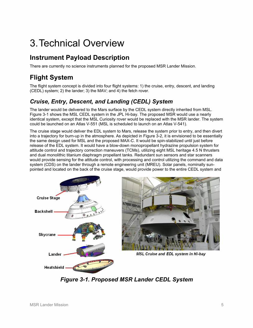
Cruise, Entry, Descent, and Landing (CEDL) System The lander would be delivered to the Mars surface by the CEDL system directly inherited from MSL. Figure 3-1 shows the MSL CEDL system in the JPL Hi-bay. The proposed MSR would use a nearly identical system, except that the MSL Curiosity rover would be replaced with the MSR lander. The system could be launched on an Atlas V-551 (MSL is scheduled to launch on an Atlas V-541).
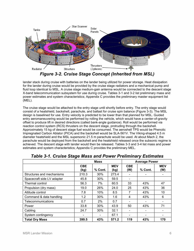
The cruise stage would deliver the EDL system to Mars, release the system prior to entry, and then divert into a trajectory for burn-up in the atmosphere. As depicted in Figure 3-2, it is envisioned to be essentially the same design used for MSL and the proposed MAX-C. It would be spin-stabilized until just before release of the EDL system. It would have a blow-down monopropellant hydrazine propulsion system for attitude control and trajectory correction maneuvers (TCMs), utilizing eight MSL heritage 4.5 N thrusters and dual monolithic titanium diaphragm propellant tanks. Redundant sun sensors and star scanners would provide sensing for the attitude control, with processing and control utilizing the command and data system (CDS) on the lander through a remote engineering unit (MREU). Solar panels, nominally sun-pointed and located on the back of the cruise stage, would provide power to the entire CEDL system and
Figure 3-1. Proposed MSR Lander CEDL System
MSR Lander Mission 6
Figure 3-2. Cruise Stage Concept (Inherited from MSL)
lander stack during cruise with batteries on the lander being utilized for power storage. Heat dissipation for the lander during cruise would be provided by the cruise stage radiators and a mechanical pump and fluid loop identical to MSL. A cruise stage medium-gain antenna would be connected to the descent stage X-band telecommunication subsystem for use during cruise. Tables 3-1 and 3-2 list preliminary mass and power estimates and system characteristics; Appendix C provides the preliminary master equipment list (MEL).
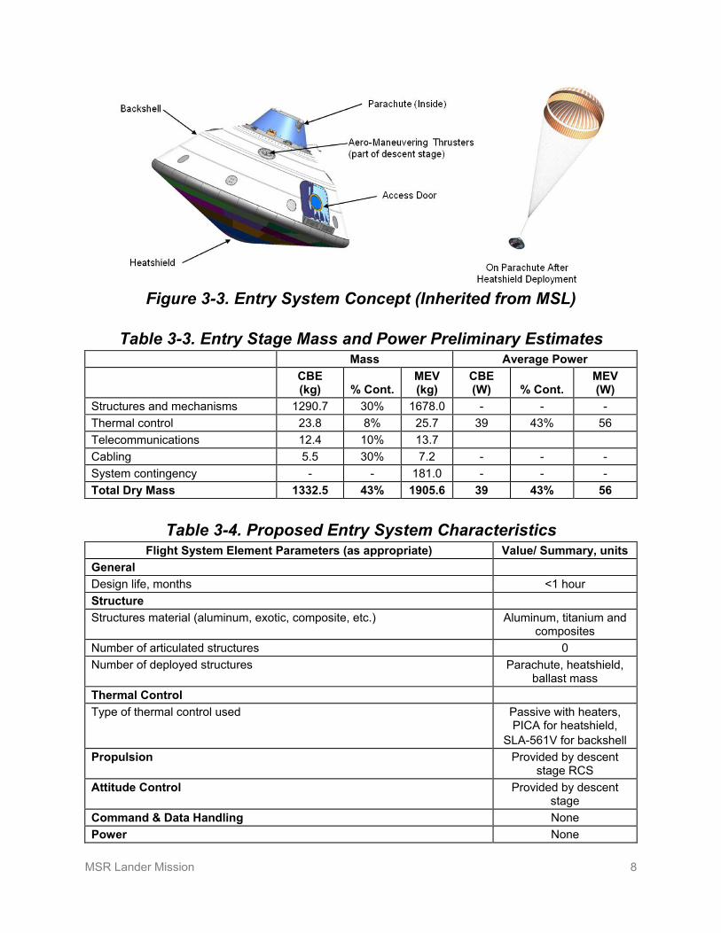
The cruise stage would be attached to the entry stage until shortly before entry. The entry stage would consist of a heatshield, backshell, parachute, and ballast for cruise spin balance (Figure 3-3). The MSL design is baselined for use. Entry velocity is predicted to be lower than that planned for MSL. Guided entry aeromaneuvering would be performed by rolling the vehicle, which would have a center-of-gravity offset to produce lift in desired directions (called bank-angle guidance). Roll would be performed via reaction control system (RCS) thrusters on the descent stage, protruding through the backshell. Approximately 15 kg of descent stage fuel would be consumed. The aeroshell TPS would be Phenolic Impregnated Carbon Ablator (PICA) and the backshell would be SLA-561V. The Viking-shaped 4.5 m diameter heatshield and the MSL supersonic 21.5 m parachute would be used. At about Mach 2, the parachute would be deployed from the backshell and the heatshield released once the subsonic regime is achieved. The descent stage with lander would then be released. Tables 3-3 and 3-4 list mass and power estimates and system characteristics; Appendix C provides the preliminary MEL.
Table 3-1. Cruise Stage Mass and Power Preliminary Estimates Mass Average Power
CBE (kg) % Cont.
MEV (kg)
CBE (W) % Cont.
MEV (W)
Structures and mechanisms 210.3 30% 273.4 - - - Spacecraft side LV adapter 45.8 30% 59.5 - Thermal control 56.3 7% 60.5 33 43% 47 Propulsion (dry mass) 19.0 26% 24.0 25 43% 36 Attitude control 7.8 10% 8.5 7 43% 10 Command & data handling 1.2 30% 1.6 4 43% 6 Telecommunications 0.7 2% 0.7 - - - Power 33.8 30% 43.9 50 43% 71 Cabling 24.7 30% 32.1 - - - System contingency - - 67.1 - - - Total Dry Mass 399.5 43% 571.2 119 43% 170

MSR Lander Mission 7
Table 3-2. Proposed Cruise Stage Characteristics Flight System Element Parameters (as appropriate) Value/ Summary, units
General Design life, months 11 months Structure Structures material (aluminum, exotic, composite, etc.) Aluminum, titanium,
composites Number of articulated structures 0 Number of deployed structures 0 Thermal Control Type of thermal control used Passive; heat-loop and
radiators for lander heat dissipation
Propulsion Estimated delta-V budget, m/s 30 m/s Propulsion type(s) and associated propellant(s)/oxidizer(s) N2H4 Number of thrusters and tanks (8) 4.5 N thrusters
(2) N2H4 tanks Specific impulse of each propulsion mode, seconds 228 s Attitude Control Control method (3-axis, spinner, grav-gradient, etc.). Spinner Control reference (solar, inertial, Earth-nadir, Earth-limb, etc.) Inertial, anti-solar Attitude control capability, degrees 50 arcsec Attitude knowledge limit, degrees 6 arcsec Agility requirements (maneuvers, scanning, etc.) – Articulation/#–axes (solar arrays, antennas, gimbals, etc.) None Sensor and actuator information (precision/errors, torque, momentum storage capabilities, etc.)
0.35 deg sun sensors, 50 arcsec star scanners,
0.005 deg/hr MIMU Command & Data Handling—Uses Lander CDS MREU and multiplex
card only Power Type of array structure (rigid, flexible, body mounted, deployed, articulated) Body mounted Array size, meters x meters 5.4 m2 Solar cell type (Si, GaAs, multi-junction GaAs, concentrators) GaAs Expected power generation at beginning of life (BOL) and end of life (EOL), watts worst case
1725 W BOL, 665 W EOL
On-orbit average power consumption, watts with 43% margin. ~665 W Battery type (NiCd, NiH, Li-ion) On lander Battery storage capacity, amp-hours N/A
MSR Lander Mission 8
Figure 3-3. Entry System Concept (Inherited from MSL)
Table 3-3. Entry Stage Mass and Power Preliminary Estimates Mass Average Power
CBE (kg) % Cont.
MEV (kg)
CBE (W) % Cont.
MEV (W)
Structures and mechanisms 1290.7 30% 1678.0 - - - Thermal control 23.8 8% 25.7 39 43% 56 Telecommunications 12.4 10% 13.7 Cabling 5.5 30% 7.2 - - - System contingency - - 181.0 - - - Total Dry Mass 1332.5 43% 1905.6 39 43% 56
Table 3-4. Proposed Entry System Characteristics Flight System Element Parameters (as appropriate) Value/ Summary, units
General Design life, months <1 hour Structure Structures material (aluminum, exotic, composite, etc.) Aluminum, titanium and
composites Number of articulated structures 0 Number of deployed structures Parachute, heatshield,
ballast mass Thermal Control Type of thermal control used Passive with heaters,
PICA for heatshield, SLA-561V for backshell
Propulsion Provided by descent stage RCS
Attitude Control Provided by descent stage
Command & Data Handling None Power None

MSR Lander Mission 9
The proposed descent stage design (Figure 3-4) is assumed to be identical to MSL, utilizing a high-throughput throttleable monopropellant hydrazine system (and He pressurant) with eight 3000 N engines for slowing descent. In addition, it has eight 267 N thrusters for not only lateral movement and attitude control during descent but also for aeromaneuvering during entry. Lightweight composite tanks being developed for the proposed MAX-C rover mission could be used to save mass, if needed. An inertial measurement unit (IMU) would be used for guidance and the MSL terminal descent radar for altitude measurement. In addition to the vertical deceleration, a ~100 m lateral maneuver would be integrated to ensure separation of the landing of platform from the backshell and parachute. The lander platform attached to the descent stage would be released and lowered to the surface in a Sky Crane mode via three tethers as the descent stage hovers approximately 10 m above the surface. Upon touchdown, the lander would cut the tethers and the descent stage would fly away to a safe distance and impact the surface. Approximately 400 kg of fuel would be consumed, including that used for entry aeromaneuvering. While descent would be controlled through the CDS on the lander, engine controllers, radar electronics, and an IMU would be part of the descent stage. Thermal batteries and an X-band telecomm system would be used during descent, while the lander X-band could be patched-in for backup and the lander UHF telecomm would be available through a UHF antenna on the descent stage. Tables 3-5 and 3-6 list mass and power preliminary estimates and system characteristics; Appendix C provides the preliminary MEL.
Figure 3-4. Proposed Descent Stage (Inherited from MSL)
Table 3-5. Descent Stage Mass and Power Preliminary Estimates Mass Average Power
CBE (kg) % Cont.
MEV (kg)
CBE (W) % Cont.
MEV (W)
Structures and mechanisms 266.6 30% 346.6 - - - Thermal control 19.0 25% 23.7 36 43% 51 Propulsion (dry mass) 214.0 2% 218.3 44 43% 63 Attitude control 46.0 3% 47.2 334 43% 478 Command & data handling 1.2 13% 1.3 3 43% 4 Telecommunications 12.9 4% 13.4 215 43% 307 Power 24.1 30% 31.3 82 43% 117 Cabling 37.4 6% 39.7 - - - Total Dry Mass 621.1 16% 721.5 714 43% 1020
Note: Fuel estimated at 389 kg for a total descent stage mass of 1110 kg.
MSR Lander Mission 10
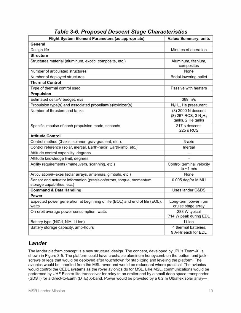
Table 3-6. Proposed Descent Stage Characteristics Flight System Element Parameters (as appropriate) Value/ Summary, units
General Design life Minutes of operation Structure Structures material (aluminum, exotic, composite, etc.) Aluminum, titanium,
composites Number of articulated structures None Number of deployed structures Bridal lowering pallet Thermal Control Type of thermal control used Passive with heaters Propulsion Estimated delta-V budget, m/s 389 m/s Propulsion type(s) and associated propellant(s)/oxidizer(s) N2H4, He pressurant Number of thrusters and tanks (8) 2000 N descent
(8) 267 RCS, 3 N2H4 tanks, 2 He tanks
Specific impulse of each propulsion mode, seconds 217 s descent, 225 s RCS
Attitude Control Control method (3-axis, spinner, grav-gradient, etc.). 3-axis Control reference (solar, inertial, Earth-nadir, Earth-limb, etc.) Inertial Attitude control capability, degrees – Attitude knowledge limit, degrees – Agility requirements (maneuvers, scanning, etc.) Control terminal velocity
to ~1 m/s Articulation/#–axes (solar arrays, antennas, gimbals, etc.) None Sensor and actuator information (precision/errors, torque, momentum storage capabilities, etc.)
0.005 deg/hr MIMU
Command & Data Handling Uses lander C&DS Power Expected power generation at beginning of life (BOL) and end of life (EOL), watts
Long-term power from cruise stage array
On-orbit average power consumption, watts 283 W typical 714 W peak during EDL
Battery type (NiCd, NiH, Li-ion) Li-ion Battery storage capacity, amp-hours 4 thermal batteries,
9 A-Hr each for EDL
Lander The lander platform concept is a new structural design. The concept, developed by JPL’s Team-X, is shown in Figure 3-5. The platform could have crushable aluminum honeycomb on the bottom and jack-screws or legs that would be deployed after touchdown for stabilizing and leveling the platform. The avionics would be inherited from the MSL rover and would be redundant where practical. The avionics would control the CEDL systems as the rover avionics do for MSL. Like MSL, communications would be performed by UHF Electra-lite transceiver for relay to an orbiter and by a small deep space transponder (SDST) for a direct-to-Earth (DTE) X-band. Power would be provided by a 6.2 m Ultraflex solar array—

MSR Lander Mission 11
similar to that used on Phoenix and planned for the MAX-C rover—with two 50 A-Hr Li-Ion batteries. A sampling system consisting of the arm, scoop, and camera baselined to be identical to that flown on Phoenix would be utilized to collect regolith and dust samples and a contingency sample, including small rocks, as backup in case rover-collected samples are not collected and returned. The Phoenix biobarrier would be used to isolate this sterilized sampling system from the rest of the lander in order to meet planetary protection requirements. The lander would carry a fetch rover, which would egress soon after landing to retrieve the sample cache left by the MAX-C rover. Upon return, the cache would be transferred to the lander using the lander arm. One of the primary functions of the lander would be to keep the MAV in a controlled thermal condition throughout the mission. The approach envisioned is to keep the MAV in an igloo of high-efficiency CO2 insulation (same type used on MSL) and nominally 27 radioisotope heater units (RHUs). Very little electrical heater power would be required, except when preparing for launch of the MAV. Preliminary analysis indicates that the MAV can be kept above its -40°C requirement while limiting thermal cycling to within half a dozen degrees. This igloo could also serve to isolate the MAV from Mars dust particles through HEPA filters as an aid to back planetary protection implemented on the orbiter. Tables 3-7 and 3-8 list mass and power preliminary estimates and system characteristics; Appendix C provides the preliminary MEL.
Figure 3-5. Proposed Lander Concept
Table 3-7. Lander Mass and Power Preliminary Estimates Mass Average Power
CBE (kg) % Cont.
MEV (kg)
CBE (W) % Cont.
MEV (W)
Cameras 3.4 12% 3.8 - - - Structures & mechanisms 212.0 30% 275.6 - - - Thermal control 45.0 30% 58.4 40 43% 57 Propulsion (dry mass) 0 0% 0 - - - Attitude control 11.2 10% 12.3 1 43% 1 Command & data handling 11.2 30% 14.6 5 43% 7 Telecommunications 15.3 13% 17.3 1 43% 1 Power 49.3 30% 64.0 19 43% 27 Cabling 39.9 30% 51.9 - - - System contingency - - 55.8 - - - Total Dry Mass 387.2 43% 553.7 66 43% 94

MSR Lander Mission 12
Table 3-8. Proposed Lander Characteristics Flight System Element Parameters (as appropriate) Value/ Summary, units
General Design life, months 2 years Structure Structures material (aluminum, exotic, composite, etc.) Primarily aluminum and
aluminum honeycomb Number of articulated structures 1 arm and scoop,
sample handling mechanisms, antenna
gimbal Number of deployed structures 1 solar array, 2 rover
egress ramps, MAV erector, 4 stabilizing legs
Thermal Control Type of thermal control used Passive with heaters,
CO2 insulation + 27 RHUs baselined for the
MAV Propulsion N/A Attitude Control Control method (3-axis, spinner, grav-gradient, etc.). 3-axis Control reference (solar, inertial, Earth-nadir, Earth-limb, etc.) Local horizontal Attitude control capability, degrees N/A Attitude knowledge limit, degrees 0.75 deg Agility requirements (maneuvers, scanning, etc.) N/A Articulation/#–axes (solar arrays, antennas, gimbals, etc.) 2 DOF 0.28 m X-band
antenna Sensor and actuator information (precision/errors, torque, momentum storage capabilities, etc.)
0.4 deg sun sensors, 0.005 deg/hr MIMU
Command & Data Handling Flight element housekeeping data rate, kbps 2 kbps Data storage capacity, Mbits 4 GB Maximum storage record rate, kbps 20 Mbps Maximum storage playback rate, kbps 2 Mbps Power Type of array structure (rigid, flexible, body mounted, deployed, articulated) Deployed UltraFlex Array size, meters x meters 6.2 m2 Solar cell type (Si, GaAs, multi-junction GaAs, concentrators) GaAs Expected power generation at beginning of life (BOL) and end of life (EOL), watt-hours/sol (sol=24.6 hours)
3301 W-Hr BOL 2982 W-Hr EOL
Worst case daily power consumption, watts 100 W Battery type (NiCd, NiH, Li-ion) Li-ion Battery storage capacity, amp-hours 100 A-Hr

MSR Lander Mission 13
Mars Ascent Vehicle (MAV) The baseline MAV, depicted in Figure 3-6, is a two-stage solid-motor design based on modifications to existing motor designs. The MAV would be housed in an igloo, while on the surface, to keep it thermally stable and fairly immune to seasonal or diurnal effects. Full-system model testing in relevant environments, including shock, storage at expected temperatures, and launch at high altitude from a balloon platform to simulate the Mars environment, is planned as part of the technology program.
The current MAV concept is based on MAV industry studies from 2002 and has been cross-checked by running the design though JPL’s Team X in 2004. Both designs had a mass of approximately 285 kg, but have been scaled to 300 kg to include 43% margin for this study. The industry studies are described in [3] and cover MAV designs based on solid, liquid, and gel propellants. The vehicle concept is 3-axis stabilized to avoid issues with payload center-of-gravity variation and nutation. The OS concept is a 17 cm sphere, estimated to weigh 5 kg, which is included in the MAV mass allocation. The concept has two stages—the first using thrust vector control for steering and the second using front-end steering using RCS. Other MAV approaches will be explored in the technology program with an emphasis on mass reduction, ease of accommodation, and reliability.
The current approach has a loose injection accuracy (±70 km), which is accommodated by targeting a 500 km orbit; a 400 km altitude is compatible with the OS remaining in orbit for well over several decades. The maneuvers for rendezvous with these variations are included as part of the orbiter propulsion budget. The OS would be released with a small spring-produced delta-V once orbit is attained so that over time, capture could be performed outside the realm of the MAV as part of the breaking-the-chain, planetary protection process.
Launch of the MAV would be a critical event that would require telemetry monitoring, transmitted during and after flight. This would necessitate that either the MSR orbiter be in place or another reliable telecommunication relay asset be available.
Tables 3-9 and 3-10 list mass and power preliminary estimates and system characteristics, which are based on the Team X version of the MAV. The detailed MEL contains proprietary and ITAR-sensitive information and is therefore not included in this report.
Figure 3-6. Two-Stage Solid Motor MAV Concept, in Proposed Launch Configuration

MSR Lander Mission 14
Table 3-9. MAV Mass and Power Preliminary Estimates Mass Average Power
CBE (kg) % Cont.
MEV (kg)
CBE (W) % Cont.
MEV (W)
Structures & mechanisms 10.3 28% 13.2 - - - Thermal control 0.8 30% 0.9 - - Propulsion dry mass (all but fuel) 25.7 30% 33.6 - - - Attitude control 5.5 22% 6.7 4.4 43% 6.3 Command & data handling 1.0 30% 1.3 1.8 43% 2.6 Telecommunications 3.0 13% 3.9 40 43% 57.2 Power 5.6 30% 7.2 48.3 43% 69.1 Cabling 2.1 24% 2.6 - - - System contingency - - 7.8 - - - Total Dry Mass 54.0 43% 77.2 94.5 43% 135.1 Note: Fuel estimated at 218 kg for total MAV mass of 300 kg (including 5 kg OS).
Table 3-10. MAV Concept Characteristics Flight System Element Parameters (as appropriate) Value/ Summary, units
General Design life, months 2 years on-orbit and
surface storage; operation < 1 week
Structure Structures material (aluminum, exotic, composite, etc.) Primarily aluminum Number of articulated structures Gimbaled nozzle Number of deployed structures OS, fairing, staging Thermal Control Type of thermal control used Passive with heaters
(igloo on lander provides control during storage)
Propulsion Estimated delta-V budget, m/s 3,690 m/s Propulsion type(s) and associated propellant(s)/oxidizer(s) Solid propellant for 1st
and 2nd stage; N2H4 for RCS
Number of thrusters and tanks (8) 22 N for steering, (4) 5 N for fine control RCS,
1 N2H4 tanks, STAR 13A,
Stretched STAR 17A Specific impulse of each propulsion mode, seconds – Attitude Control Control method (3-axis, spinner, grav-gradient, etc.). 3-axis Control reference (solar, inertial, Earth-nadir, Earth-limb, etc.) Inertial Attitude control capability, degrees ±1.4 deg Attitude knowledge limit, degrees ±0.18 deg

MSR Lander Mission 15
Flight System Element Parameters (as appropriate) Value/ Summary, units Agility requirements (maneuvers, scanning, etc.) – Articulation/#–axes (solar arrays, antennas, gimbals, etc.) – Sensor and actuator information (precision/errors, torque, momentum storage capabilities, etc.)
IMU 1st stage thrust vector
control Command & Data Handling Flight element housekeeping data rate, kbps Low Data storage capacity, Mbits 4 GB Maximum storage record rate, kbps 8 Mbits/s Maximum storage playback rate, kbps 8 Mbits/s Power Type of array structure (rigid, flexible, body mounted, deployed, articulated) None Array size, meters x meters – Solar cell type (Si, GaAs, multi-junction GaAs, concentrators) – Expected power generation – Average power consumption, watts 135 W Battery type (NiCd, NiH, Li-ion) Li-ion primary charged
from lander and 1 thermal battery
Battery storage capacity, amp-hours 1 A-Hr
Fetch Rover After the rock cores have been cached by the proposed MAX-C rover mission, a single-purpose fetch rover would be utilized to retrieve the cache. A concept emerging from a concept study team led to a Team X point design study in September 2009. The concept is similar to MER but without instruments. A 1-DOF arm would be used to pick up the cache from the surface, using rover positioning to insert the arm end-effecter into loops envisioned on the cache. Figure 3-7 shows the fetch rover concept in relation to a MER. MSL heritage avionics would be used with low-temperature distributed motor-controllers to save mass, which are currently being developed and should have been demonstrated on the MAX-C rover. Selective redundancy, consistent with its short mission duration, would be implemented for key components to address fault tolerance. It would have similar trafficability as MER, but would utilize enhanced avionics and driving capability to increase effective speed, planned as part of the technology program for the MAX-C rover mission. These upgrades would enable close-to-continuous driving unlike the low duty cycle of MER, where most of the time would be taken for computation between short moves. Even with the lander targeting the MAX-C rover cache location, ~14 km traverse might be needed, which would be possible with the proposed MAX-C rover developed upgrades. MSL-heritage mobility actuators would be used, which are designed for MSL’s 20 km distance requirement. Four navigation cameras (MER nav cams) would be mounted as stereo sets on the front and back of the chassis, rather than on a mast; four hazard cameras (MER haz cams) would also be mounted on the lower end of the front and back. With the MSR orbiter planned to be in place before the MSR Lander Mission, reliance on UHF relay communications to the orbiter is assumed, eliminating the need for the MER X-band DTE system. Since the mast and X-band antenna could be eliminated, the upper deck of the rover would be open, allowing unique rotating solar array deployment that could be used not only to save stowed configuration space, but also to potentially provide a means of cleaning dust accumulation. Tables 3-11 and 3-12 list mass and power preliminary estimates and system characteristics; Appendix C provides the preliminary MEL.

MSR Lander Mission 16
Figure 3-7. Fetch Rover Concept in Relation to MER
Table 3-11. Fetch Rover Mass and Power Preliminary Estimates Mass Average Power
CBE (kg) % Cont.
MEV (kg)
CBE (W) % Cont.
MEV (W)
Structures & mechanisms 67.2 30% 87.3 8 43% 11.4 Thermal control 1.0 22% 1.2 10 43% 14.3 Propulsion (dry mass) - - - - - - Attitude control 2.6 7% 2.8 4 43% 5.7 Command & data handling 8.5 12% 10.3 13 43% 18.6 Telecommunications 3.3 10% 3.7 1 43% 1.4 Power 21.6 30% 28.1 10 43% 14.3 Cabling 5.8 30% 7.6 - - - System contingency - - 16.3 - - - Total Dry Mass 110.0 43% 157.3 46 43% 65.8
Table 3-12. Proposed Fetch Rover Characteristics Flight System Element Parameters (as appropriate) Value/ Summary, units
General Design life, months <1 year cruise, <1 year on
surface Structure Structures material (aluminum, exotic, composite, etc.) Primarily aluminum Number of articulated structures 6 wheels, 4 wheel
steering (1) 1-DOF arm
Number of deployed structures 4 solar array panels

MSR Lander Mission 17
Flight System Element Parameters (as appropriate) Value/ Summary, units Thermal Control Type of thermal control used Passive with heaters,
CO2 insulation Attitude Control Control method (3-axis, spinner, grav-gradient, etc.). 3-axis Control reference (solar, inertial, Earth-nadir, Earth-limb, etc.) Inertial & surface features Attitude control capability, degrees - Attitude knowledge limit, degrees - Agility requirements (maneuvers, scanning, etc.) Wheel steering Articulation/#–axes (solar arrays, antennas, gimbals, etc.) None Sensor and actuator information (precision/errors, torque, momentum storage capabilities, etc.)
4 navigation cameras 4 hazard cameras
LN-200S IMU Command & Data Handling Flight element housekeeping data rate, kbps Low Data storage capacity, Mbits 64 Mbytes Maximum storage record rate, kbps 1.6 Mbits/s Maximum storage playback rate, kbps 1.6 Mbits/s Power Type of array structure (rigid, flexible, body mounted, deployed, articulated)
Rigid, deployed and body mounted
Array size, meters x meters 2.7 m2 Solar cell type (Si, GaAs, multi-junction GaAs, concentrators) GaAs Worstcase average power available dependent on latitude, time of year, dust coverage and cell degradation.
75 W
Average power consumption, watts 70 W Battery type (NiCd, NiH, Li-ion) Li-ion Battery storage capacity, amp-hours 46 A-Hr
Concept of Operations and Mission Design The nominal sequence of the proposed MSR campaign would start with the MAX-C rover mission that would be launched in 2018, resulting in a sample cache left on the martian surface roughly 2 years later in 2020. The MSR Orbiter Mission would be nominally launched in 2022, followed by the lander in 2024. Figure 3-8 shows a representative timeline. Table 3-13 provides the parameters that reflect the 2024 opportunity.
The proposed MSR lander would launch from Cape Canaveral on 10/2024 on an Atlas V-551 or comparable vehicle with a C3 of approximately 12.2. On a Type-II trajectory, the lander would arrive at Mars in September 2025. Once on the surface, the fetch rover would be dispatched to retrieve the cache left by the MAX-C rover. The plan is to have the MAX-C rover deliver the cache to a location that would be well within the landing ellipse of the MSR lander. The fetch rover might have to traverse 14 km round-trip in a worst case of landing in relation to the cache. It is anticipated that the cache return could be accomplished within 3 months. Collection of a regolith sample at the lander would be performed during that time. In order to leave adequate time for the MSR Orbiter Mission to accomplish rendezvous with the OS and set up for Earth return, the MAV should launch around May 2026, approximately eight months after arrival. In the event that surface operations would take more than eight months, the MSR Orbiter Mission would have the fuel to wait for an opportunity before return.

MSR Lander Mission 18
Figure 3-8. Representative Lander Mission Timeline in Relation to the Orbiter Mission
Table 3-13. Mission Design Concept Parameter Value Units
Mission lifetime <2 Years Maximum eclipse period 14 Hours Launch site CCAFS – Total flight system mass with contingency 4598 Kg Propellant mass without contingency – Kg Propellant contingency – % Propellant mass with contingency – for cruise only 70 Kg Launch adapter mass with contingency (included in cruise stage mass)
60 Kg
Total launch mass 4668 Kg Launch vehicle Atlas V-551 Type Launch vehicle lift capability 5130 Kg Launch vehicle mass margin 462 Kg Launch vehicle mass margin (%) 9 %
Communications for the proposed lander would be through the Deep Space Network (DSN) once per day and up to two passes of relay though the MSR orbiter. DSN coverage for the orbiter relay is included in the MSR Orbiter Mission concept study report [2]. DSN near-continuous coverage would be needed for tracking around TCM maneuvers while enroute to Mars and during the critical events of EDL and MAV launch. All fetch rover communications would be through UHF relay to the MSR orbiter. Table 3-14 summarizes the need for coverage. Without science instruments, data volume would be low; therefore, X-band would be adequate. The Decadal Survey guidelines indicate that Ka-band should be used post-2016. It is believed that X-band might still be available. However, Ka-band could be used (at a cost of $5M–$10M) and would have insignificant mass and volume impacts.

MSR Lander Mission 19
Table 3-14. Mission Operations and Ground Data Systems
Downlink Information Nominal Phases EDL & Maneuvers & MAV
Launch Number of contacts per week 7 Continuous Number of weeks for mission phase, weeks Throughout 6 days each
x 6 Downlink frequency band, GHz – 8.4 GHz X-band X-band Telemetry data rate(s), kbps 10 kbps 10 kbps Transmitting antenna type(s) and gain(s), DBi 0.28 m HGA 0.28 m HGA Downlink receiving antenna gain, DBi 34 m DSN 34 m DSN Transmitting power amplifier output, watts 15 watts 15 watts Total daily data volume, (MB/day) 170 Mb 170 Mb
Uplink Information Number of uplinks per day 1 per day Several Uplink frequency band, GHz – 7.2 GHz X-band X-band Telecommand data rate, kbps 2 kbps 2 kbps Receiving antenna type(s) and gain(s), DBi 1.0 m HGA 1.0 m HGA
Planetary Protection This proposed mission would be classified as Category IVb. The proposed approach would be a IVb-subsystem implementation, where all hardware that might touch the sample must be sterilized and cleaned, with bio-barriers to protect that hardware from recontamination from other sources. The affected hardware would be the regolith arm and scoop and any sample handling and transfer hardware. The use of the Phoenix Mars arm/scoop and biobarrier design would meet this need. The sample handling transfer and packaging mechanisms must be enclosed in a biobarrier that would be only opened as needed.
Risk List Table 3-15 lists the top mission and implementation risks for the proposed MSR Lander Mission. Figure 3-9 correlates the likelihood and impact on a 5 x 5 risk matrix (with risk level color coding of green = low, yellow = medium, and red = high). Table 3-16 is a key to risk assessment.
Table 3-15. Top Risks for the Proposed Lander Mission Risk Level Description Impact Likelihood Mitigation
1. Lander is late in delivery of the OS for rendezvous.
M Difficulty in cache retrieval or delayed events leading to MAV launch might delay planned Earth return of the orbiter. The return would be delayed by 2 years.
5 1 Orbiter Mission to carry the fuel to support a 2-year slip in return. Fuel impact is small. Operations cost would be extended 2 years.
2. MAV development is more difficult than planned.
L MAV development is new. Significant mass or accommodation growth might cause redesign / rescope of the lander.
3 1 Implement a technology program to develop and flight test MAV prior to the mission PDR, and start early with incremental qualification steps. Current plan starts 7 years prior to the PDR.

MSR Lander Mission 20
Risk Level Description Impact Likelihood Mitigation 3. Sample handling on lander proves more difficult than planned.
L The necessary hardware to package the regolith has not been designed, nor has the OS design been updated since 2000. Phoenix has shown that handling loose material can be challenging.
2 2 Carry multiple solutions and back-off positions. Develop strawman designs in Pre-Phase A. Revisit previous designs from 1999 project. Consider using the proposed MAX-C core packaging design.
4. MAX-C rover does not bring cache back into the potential landing ellipse
M The current design assumes the traverse for a round-trip fetch rover within the design distance of MSL (actuator lifecycles) of 20 km. Outside this distance is considered unacceptable risk.
5 1 Build in constraints on proposed MAX-C exploration envelope.
5. MAX-C rover fails with cache attached
M The current fetch rover is designed for surface cache pickup, not removal from MAX-C.
5 1 Add feature to MAX-C design that would allow simple release of cache to ground from a non-operating rover.
6. MAX-C EDL solution is not applicable to MSR-L
L MSR-L landing needs might be different than that implemented on MAX-C
2 1 EDL and platform design process for MAX-C will take into account MSR-L considerations and seek common solutions
2
6 3 1, 4,5
Figure 3-9. 5 x 5 Risk Matrix
Like
lihoo
d
1 2 3 4 5 Impact
5
4
3
2
1

MSR Lander Mission 21
Table 3-16. Risk Level Definitions
Levels Mission Risk Implementation Risk
Impact Likelihood of Occurrence Impact Likelihood of
Occurrence
5
Mission failure Very high, >25%
Consequence or occurrence is not repairable without engineering (would require >100% of margin)
Very high, ~70%
4
Significant reduction in mission return (~25% of mission return still available)
High, ~25% All engineering resources will be consumed (100% of margin consumed)
High, ~50%
3
Moderate reduction in mission return (~50% of mission return still available)
Moderate, ~10%
Significant consumption of engineering resources (~50% of margin consumed)
Moderate, ~30%
2
Small reduction in mission return (~80% of mission return still available)
Low, ~5% Small consumption of engineering resources (~10% of margin consumed)
Low, ~10%
1
Minimal (or no) impact to mission (~95% of mission return still available)
Very low, ~1% Minimal consumption of engineering resources (~1% of margin consumed)
Very low, ~1%

MSR Lander Mission 22
4. Development Schedule and Schedule Constraints
High-Level Mission Schedule Figure 4-1 shows the development and schedule for the proposed MSR Lander Mission (planned for launch in 2024) and the associated technology development phase of the MAV culminating in flight tests.
Table 4-1 lists the duration of key phases of proposed Lander Mission development.
Figure 4-1. Development Schedule for the Proposed Lander Mission
Table 4-1. Proposed Key Phase Duration Project Phase Duration (Months)
Phase A – Conceptual Design 18 months Phase B – Preliminary Design 13 months Phase C – Detailed Design 20 months Phase D – Integration & Test 26 months Phase E – Primary Mission Operations 20 months Phase F – Extended Mission Operations None Start of Phase B to PDR 11 months Start of Phase B to CDR 23 months Project total funded schedule reserve Built in to schedule (~1 month/year) Total development time Phase B–D 59 months
Technology Development Plan Only one technology would not have been addressed by the proposed MAX-C and prior missions—the development of the MAV. While the component-level technology needed is relatively minor, the qualification of the elements for the mission environments, and the MAV as a system, is planned as part of the MSR technology program and would be completed prior to the mission PDR.
A NASA Research Announcement (NRA) has been released this year as part of NASA’s Research Opportunities for Space and Earth Sciences (ROSES), sponsored by the NASA-GRC In-Space Propulsion (ISP) program. This plan begins with MAV system studies, initiated by the end of this fiscal
MSR Lander Mission 23
year (FY) and culminates in the demonstration of at least one MAV propulsion system within three years. Results of a MAV request for information (RFI) issued last year indicate that several concepts might be worth pursuing. If current plans are sustained over the three-year period, either the baseline concept (described in this report) or an alternate concept or variation will be selected and enough propulsion system-level testing will have been accomplished to have confidence in starting full-fledged MAV system development.
The MAV technology program is designed to provide the project with a qualified MAV system, ready for manufacture and acceptance testing of the flight unit with minimal change. While the baseline MAV concept relies on existing technologies, the reliable operation of those technologies as a system under the environmental conditions required by a Mars mission still needs to be demonstrated. The technology program is envisioned to incrementally qualify components, then systems (such as motors), then stages, and finally a full flight system. Environmental qualification at each of these levels would include not only low temperature and thermal cycling over mission lifetimes, but also tolerance to loads that would be experienced during launch, entry, and landing. Ground-based performance testing, potentially including surface launch of the first stage, would be performed. Ultimately, a full MAV system would be flight tested at high altitude (62,000 feet) from a balloon platform. Three tests are planned prior to the mission PDR with at least two successful flights required, one of which must have been through full environmental qualification.
For the purposes of this report, the full MAV technology program is budgeted in the project in parallel with pre-Phase A through Phase B development activities, starting in FY16. The total cost budgeted is $274M (RY) with a five-year profile as shown in Section 5.
Development Schedule and Constraints There is nothing unusual about the proposed MSR Lander Mission that would indicate schedule issues at this point in planning. Care has been taken to adequately plan MAV technology development to start next year and to achieve environmental qualification and high-altitude flight test prior to the mission PDR.
Launch opportunities to Mars occur roughly every 26 months; thus, if the spacecraft was not ready for launch, a two-year slip would occur.

MSR Lander Mission 24
5. Mission Life-Cycle Cost Costing Methodology and Basis of Estimate The proposed MSR Lander Mission design and cost have been developed by JPL’s Team X using their quasi-grassroots process. Combinations of grassroots, parametric analysis, and analogy models are used by each of the discipline chairs representing their implementing organizations. These models have been validated against actual costs of prior JPL missions.
The Team X study was performed in October 2009. Costs have been modified to meet the Decadal Survey guidelines of 50% reserves for development (Phases A–D) and 25% for operations (Phase E).
A separate fetch rover Team X study was performed in September 2009, the results of which were rolled into the MSR lander study, the following month.
The MAV was studied by Team X in 2004 and those costs have been carried forward into subsequent Team X studies, including the October 2009 lander study. The development (Phases A–D) costs for the MAV assume that technology development for the MAV (funded at $250M [FY15]) would take a flight-like unit through full environmental qualification and high-altitude flight testing.
All costs have been inflated to FY 2015 dollars and real year (RY) dollars for a 2024 launch, as requested by the Decadal Survey.
Launch vehicle cost is as specified in the Decadal Survey ground rules for mission studies.
Technology development cost estimates for the MAV are based on modification of MAV industry study results from 2002 [3], two MSR technology reviews (in 2005 and 2008), and most recently an independent review by Aerospace Corporation. MAV technology development costs include 50% reserve.
Cost Estimates Table 5-1 summarizes the total mission estimated costs for the proposed MSR Lander Mission.

MSR Lander Mission 25
Table 5-1. Total Estimated Mission Cost Funding Profile (FY Costs in Real Year Dollars, Totals in Real Year and 2015 Dollars)
FY 2016 2017 2018 2019 2020 2021 2022 2023 2024 2025 2026 Total RY Total FY15
Pre-Phase-A 6 10 16 15 Technology Development 15 27 86 86 60 274 250 Development A–D
Proj Mgmt/SE/MA 2 6 16 38 48 50 45 4 209 171 Flight Sys Mgmt/SE 2 4 7 21 26 26 26 2 114 94 Mars Ascent Vehicle 13 11 11 12 1 48 39 Fetch Rover 1 4 20 42 59 60 20 4 210 172 Lander 2 6 24 63 77 79 75 5 331 272 Descent Stage 2 4 10 28 40 41 29 3 157 129 Entry (with analysis) 1 1 8 21 29 29 16 3 108 89 Cruise Stage 1 2 7 22 27 27 20 2 108 89 MSI&T 2 6 10 24 28 29 1 100 82 Ground Data System Dev 1 3 8 10 10 11 1 44 36 MOS Prep & Mission Design 1 5 12 15 15 15 2 65 53 Prelaunch Science 1 2 3 3 3 1 13 11 Total A_D w/o Reserves 11 31 107 280 369 379 301 29 1507 1238 A-D Reserves 5 15 54 140 184 190 150 15 753 619
Total A–D Cost 16 46 161 420 553 569 451 44 2260 1857 Launch Services 38 150 140 6 334 272 Phase E Phase E Science 6 6 12 9
Other Phase E Costs 35 31 66 50 Phase E Reserves 10 10 20 15
Total Phase E 51 47 98 74 DSN 4 7 7 18 14 Education/Outreach 1 1 1 1 2 8 8 22 17 Total Mission Costs 21 37 102 132 222 421 592 720 597 116 62 3022 2499
Notes: MSI&T—Mission System Integration and Test and Includes all costs to NASA including estimated DSN costs.
preparation for operations.

MSR Lander Mission 26
Appendix A. Acronyms BOL beginning of life
CBE current best estimate
CDS command and data system
CEDL cruise, entry, descent, and landing
CML concept maturity level
DSN Deep Space Network
DTE direct-to-Earth
EDL entry, descent, and landing
EEV Earth Entry Vehicle
EOL end of life
FY fiscal year
IMU inertial measurement unit
MAV Mars Ascent Vehicle
MEL master equipment list
MEV maximum expected value
MREU MSAP remote engineering unit
MRSH Mars Returned Sample Handling
MSR Mars Sample Return
OS orbiting sample
PDR Preliminary Design Review
PICA Phenolic Impregnated Carbon Ablator
RCS reaction control system
RFI request for information
RHU radioisotope heater unit
RY real year
SAG Science Advisory Group
SDST small deep space transponder
SRF sample receiving facility
TCM trajectory correction maneuver
TPS thermal protection system
UHF ultra-high frequency

MSR Lander Mission 27
Appendix B. References [1] National Aeronautics and Space Administration. March 2010. Mission Concept Study: Planetary
Science Decadal Survey—Mars 2018 MAX-C Caching Rover.
[2] National Aeronautics and Space Administration. March 2010. Mission Concept Study: Planetary Science Decadal Survey—MSR Orbiter Mission (including Mars Returned Sample Handing).
[3] Stephenson, D., “Mars Ascent Vehicle—Concept Development,” NASA-Marshall Space Flight Center, Huntsville, AL, 38th Joint Propulsion Conference and Exhibit, July 7–10, 2002, Paper #4318.
MSR Lander Mission 28
Appendix C. Lander Mission Master Equipment Lists from Team X Studies The following MELs are included in this appendix:
• Cruise Stage
• Entry System
• Descent Stage
• Lander
• Fetch Rover

MSR Lander Mission 29
Cruise Stage Preliminary MEL
Component Flt Units CBE/Unit (kg/unit) CBE (kg) Cont. CBE + Cont.
(kg)
Sun Sensors 2 2.40 4.80 10% 5.28Star Trackers 2 1.48 2.95 10% 3.25
Telemetry Mulitplex Card (TMC): CRC Card (NR) 1 0.40 0.40 30% 0.52MREU: MSAP Analog/Discrete MREU 1 0.80 0.80 30% 1.04
Solar Array 1 7.73 7.73 30% 10.05Chassis 1 3.93 3.93 30% 5.11Array Segment Switches* - Array Interface Slice Boards 2 2.22 4.44 30% 5.77Load Switches - LCC Boards 4 1.00 4.00 30% 5.20Thruster Drivers* - GID Boards 2 1.10 2.20 30% 2.86Houskeeping DC-DC Converters* Boards 2 1.13 2.26 30% 2.94Power/Shunt Control* - Shunt Driver Slice Boards 2 4.00 8.00 30% 10.40Shielding 1 1.24 1.24 30% 1.62
Gas Service Valve 2 0.23 0.46 2% 0.47Temp. Sensor 1 0.01 0.01 5% 0.01Liq. Service Valve 1 0.28 0.28 2% 0.29LP Transducer 2 0.27 0.54 2% 0.55Liq. Filter 1 0.40 0.40 2% 0.41LP Latch Valve 2 0.35 0.70 2% 0.71Temp. Sensor 34 0.01 0.34 5% 0.36Lines, Fittings, Misc. 1 3.00 3.00 50% 4.50Monoprop Main Engine 8 0.38 3.04 10% 3.34Pressurant Tanks 1 0.00 0.00 0% 0.00Fuel Tanks 2 5.13 10.26 30% 13.34
Primary Structure 1 100.63 100.63 30% 130.82Secondary Structure 1 21.77 21.77 30% 28.30Thruster Support Structure 1 5.22 5.22 30% 6.79Prop Support Structure 1 2.98 2.98 30% 3.87Radiator Panels 1 53.06 53.06 30% 68.98Separation Devices 1 16.27 16.27 30% 21.15Cruise Stage PAI &CM 1 9.90 9.90 30% 12.87Purge Hardware 1 0.44 0.44 30% 0.57Cabling Harness 1 24.70 24.70 30% 32.11Adapter, Spacecraft side 1 45.75 45.75 30% 59.48
X-MGA (19dB) MER 1 0.37 0.37 2% 0.38Other 1 0.28 0.28 2% 0.29
Multilayer Insulation (MLI) 20 0.40 8.00 20% 9.60 Paints/Films 10 0.25 2.50 15% 2.88General 1 0.49 0.49 0% 0.49Custom 4 0.28 1.10 20% 1.32Propulsion Tank Heaters 2 0.10 0.20 20% 0.24Propulsion Line Heaters 6 0.10 0.60 20% 0.72PRT's 78 0.00 0.12 5% 0.12Mechanical 4 0.01 0.05 20% 0.06Thermal Radiator (Area=m2) 1 7.50 7.50 5% 7.88CIPAS 1 22.65 22.65 2% 23.10HRS Tube Assy 1 6.11 6.11 5% 6.42HRS CFC-11 1 6.34 6.34 10% 6.97HRS Tube Epoxy 1 0.20 0.20 20% 0.24Fluid (P-Clamp+Bulk Jam Nut) 1 0.46 0.46 5% 0.48
Thermal
Attitude Determination and Control System
Command and Data System
Power
Propulsion
Structures
Telecomm

MSR Lander Mission 30
Entry System Preliminary MEL
Component Flt Units CBE/Unit (kg/unit) CBE (kg) Cont. CBE + Cont.
(kg)
Backshell 1 484.52 484.52 30% 629.88Heatshield 1 420.50 420.50 30% 546.65Parachute 1 88.22 88.22 30% 114.69Cruise Ballast 1 138.70 138.70 30% 180.31Entry Ballast 1 158.80 158.80 30% 206.44Cabling Harness 1 5.52 5.52 30% 7.18
X-LGA MER/MPF CWG 2 0.41 0.82 2% 0.84UHF-MGA array 1 7.86 7.86 7% 8.41Waveguide Transfer Switch (WGTS) 2 0.44 0.88 2% 0.90Polarizer 2 0.27 0.54 25% 0.68Other 2 0.05 0.10 30% 0.13Other 2 0.03 0.06 10% 0.07WR-112 WG, rigid (Al) 4 0.45 1.80 30% 2.34Coax Cable, flex (190) 1 0.26 0.26 2% 0.27Coax Cable, flex (120) 1 0.12 0.12 2% 0.12
Multilayer Insulation (MLI) 5 2.05 10.25 15% 11.79General 1 0.73 0.73 0% 0.73 Isolation (G-10) 1 0.00 0.00 0% 0.00 High Conductance 1 0.00 0.00 0% 0.00Catalogue 1 0.05 0.05 0% 0.05Custom 1 0.05 0.05 0% 0.05Propulsion Tank Heaters 1 0.10 0.10 0% 0.10Propulsion Line Heaters 1 0.10 0.10 0% 0.10Temperature Sensors 1 0.00 0.00 0% 0.00Thermistors 1 0.02 0.02 0% 0.02PRT's 1 0.01 0.01 0% 0.01Mechanical 1 0.02 0.02 0% 0.02Electronic 1 0.01 0.01 0% 0.01Thermal Louvers 1 0.98 0.98 0% 0.98Thermal Radiator (Area=m2) 1 10.50 10.50 0% 10.50Ext SLI 1 1.03 1.03 30% 1.34
Telecomm
Thermal
Structures

MSR Lander Mission 31
Descent Stage Preliminary MEL
Component Flt Units CBE/Unit (kg/unit) CBE (kg) Cont. CBE + Cont.
(kg)
IMUs 1 4.00 4.00 10% 4.40Terminal Descent Sensor 1 23.60 23.60 2% 24.07Descent Motor Controller 1 18.39 18.39 2% 18.76
Telemetry Mulitplex Card (TMC): CRC Card (NR) 1 0.40 0.40 30% 0.52MREU: MSAP Analog/Discrete MREU 1 0.80 0.80 5% 0.84
Thermal Battery (Thermal Battery) 4 0.51 2.04 30% 2.65Chassis 1 3.54 3.54 30% 4.61Load Switches (LCC) Boards 6 1.00 6.00 30% 7.80Thruster Drivers* - MSL GID Boards 2 1.10 2.20 30% 2.86Pyro Switches* (DPRA) Boards 4 1.64 6.56 30% 8.53Houskeeping DC-DC Cnvrtrs* (HPCU) Boards 2 1.13 2.26 30% 2.94Shielding 1 1.45 1.45 30% 1.89
Gas Service Valve 4 0.23 0.92 2% 0.94HP Transducer 1 0.27 0.27 2% 0.28Gas Filter 1 0.75 0.75 2% 0.77NC Pyro Valve 2 0.67 1.34 2% 1.37NC 3/8" Pyro Valve 2 0.30 0.60 2% 0.61Press Regulator 1 1.60 1.60 15% 1.84Temp. Sensor 2 0.01 0.02 5% 0.02Rectify to MSL PCA mass of 8.94kg 1 1.70 1.70 0% 1.70Liq. Service Valve 3 0.28 0.84 2% 0.86Test Service Valve 1 0.23 0.23 2% 0.24LP Transducer 3 0.27 0.81 2% 0.83Liq. Filter 1 0.45 0.45 2% 0.46LP Latch Valve 2 0.35 0.70 2% 0.71NC Pyro Valve 6 0.67 4.02 10% 4.42NC 3/8" Pyro Valve 2 0.30 0.60 10% 0.66Mass Flow Control 4 0.03 0.12 50% 0.18Temp. Sensor 10 0.01 0.10 5% 0.11Water flow test bed 1 0.00 0.00 0% 0.00Lines, Fittings, Misc. 10 5.40 54.00 10% 59.40Monoprop Main Engine 8 9.10 72.80 10% 80.08Monoprop Thrusters 1 8 0.74 5.92 10% 6.51Pressurant Tanks 2 9.12 18.24 30% 23.71Fuel Tanks 3 15.99 47.97 30% 62.36
Primary Structure 1 178.30 178.30 30% 231.79Secondary Structure 1 15.76 15.76 30% 20.48Separations 1 10.41 10.41 30% 13.53BUD 1 32.28 32.28 30% 41.96Prop Structure 1 17.20 17.20 30% 22.36DS Centering Mass 1 11.80 11.80 30% 15.34Purge Hardware 1 0.84 0.84 30% 1.09Cabling Harness 1 37.42 37.42 30% 48.65
Attitude Determination and Control System
Command and Data System
Power
Propulsion
Structures

MSR Lander Mission 32
Component Flt Units CBE/Unit (kg/unit) CBE (kg) Cont. CBE + Cont.
(kg)
X-LGA MER/MPF CWG 1 0.35 0.35 2% 0.36UHF-LGA Monopole 1 0.60 0.60 2% 0.61SDST X-up/X down 1 3.01 3.01 2% 3.07X-band TWTA RF=100W 1 2.46 2.46 2% 2.51Waveguide Transfer Switch (WGTS) 2 0.44 0.88 2% 0.90X-band Isolator 1 0.52 0.52 2% 0.53Filter, low power 2 0.07 0.14 2% 0.14Filter, high power 2 0.38 0.76 2% 0.78X-band Diplexer, high isolation 1 0.63 0.63 2% 0.64Polarizer 1 0.26 0.26 2% 0.27Other 1 0.06 0.06 2% 0.06Coax Transfer Switch (CXS) 1 0.12 0.12 5% 0.13Other 1 0.05 0.05 2% 0.05WR-112 WG, rigid (Al) 4 0.56 2.22 10% 2.44Coax Cable, flex (190) 4 0.14 0.56 10% 0.61Coax Cable, flex (120) 1 0.29 0.29 10% 0.31
Multilayer Insulation (MLI) 26 0.38 9.75 30% 12.68Paints/Films 5 0.02 0.12 20% 0.14General 1 0.71 0.71 20% 0.86Custom 46 0.10 4.60 20% 5.52PRT's 140 0.00 0.21 5% 0.22Mechanical 20 0.01 0.26 20% 0.31HRS Tube Assy 1 2.23 2.23 20% 2.68HRS Epoxy 1 0.56 0.56 10% 0.62HRS Fluid (CFC-11) 1 1.10 1.10 30% 1.43Fluid System P-Clamps 12 0.01 0.12 5% 0.13Fluid System Mech Jt Jam Nuts 9 0.01 0.09 5% 0.10
Thermal
Telecomm

MSR Lander Mission 33
Lander Preliminary MEL
Component Flt Units CBE/Unit (kg/unit) CBE (kg) Cont. CBE + Cont.
(kg)
Lander Cameras 3 0.30 0.90 2% 0.92Robotic Arm Camera 1 1.60 1.60 15% 1.84Sample Insertion Camera 1 0.30 0.30 15% 0.35Descent Cameras 2 0.30 0.60 15% 0.69
Sun Sensor 1 3 0.06 0.17 30% 0.22IMU 1 1 4.00 4.00 10% 4.40SA Gimbal Drive Electronics 2 1.00 2.00 10% 2.20HGA Gimbal Drive Electronics 2 1.00 2.00 10% 2.20Lander arm Electronics 2 1.00 2.00 10% 2.20Sampling handling Electronics 1 1.00 1.00 10% 1.10
Processor: MSAP Enhanced SFU (3U) 133MHz 2 0.55 1.10 30% 1.43MTIF: MSAP MTIF Card (6U) 2 0.77 1.54 30% 2.00CRC: CRC Card (NR) 2 0.40 0.80 30% 1.04NVMCAM: MUC (Mission Unique Card) (NR) 2 1.00 2.00 30% 2.601/2 Sized Backplane & Chassis: MSAP Backplane with 1/2 Enclosure 2 1.30 2.60 30% 3.38
PCC: MSAP PCC DC -DC Converter: 5 V, 3.3V and +/-12V. 2 0.80 1.60 30% 2.08
MREU: MSAP Analog/Discrete MREU 2 0.80 1.60 30% 2.08
Solar Array 1 11.21 11.21 30% 14.58Li-ION (Secondary Battery) 2 9.60 19.20 30% 24.96Chassis 1 5.59 5.59 30% 7.26Array Segment Switches* - MSL/MSAP Array Interface Slice Boards 2 0.80 1.60 30% 2.08
Load Switches - MSL Load Control Card (LCC) Boards 4 0.80 3.20 30% 4.16
Pyro Switches* - Pyro Firing Card (PFC) Boards 2 0.80 1.60 30% 2.08Houskeeping DC-DC Converters* (HPCU) Boards 2 1.00 2.00 30% 2.60MSl/MSAP Power Bus Controller Boards 1 1.00 1.00 30% 1.30Battery Control - MSL Battery Control Board Boards 3 0.80 2.40 30% 3.12Shielding 1 1.45 1.45 30% 1.89
Primary Structure 1 68.85 68.85 30% 89.50Secondary Structure 1 19.00 19.00 30% 24.70Solar Array Latch/Release/Deploy Hinge 1 1.75 1.75 30% 2.28Antenna Gimbal Assemblies 1 6.70 6.70 30% 8.71Rover Egress 2 7.00 14.00 30% 18.20Rover Mobility Tie-Downs 6 1.50 9.00 30% 11.70Rover Lift Mechanism 1 5.20 5.20 30% 6.76Rover Umbilical Cutter, Retractor & Tower 1 2.60 2.60 30% 3.38MAV Support Releases 1 3.50 3.50 30% 4.55MAV Erection Mechansim 1 15.00 15.00 30% 19.50MAV Barrier Support Structure 1 10.00 10.00 30% 13.00Sample Transfer Mechanism to MAV 1 15.00 15.00 30% 19.50Lander Arm and Bio Barrier 1 5.56 5.56 30% 7.23Lander Arm Launch Locks 2 0.50 1.00 30% 1.30Lander Electronics Box 1 8.50 8.50 30% 11.05Lander Bridle & Umbilial Cutters with Towers 1 6.60 6.60 30% 8.58Lander Balancing Mechanism 3 3.50 10.50 30% 13.65HGA Launch Locks 1 0.50 0.50 30% 0.65Integration Hardware 1 4.82 4.82 30% 6.27Balance Mass 1 3.90 3.90 30% 5.07
Command and Data System
Structures
Power
Instruments
Attitude Determination and Control System

MSR Lander Mission 34
X-HGA (22dB) MPF 1 1.60 1.60 10% 1.76X-LGA MER/MPF CWG 1 1.00 1.00 10% 1.10UHF-LGA MSL Helix 1 0.56 0.56 10% 0.62SDST X-up/X down 1 2.70 2.70 10% 2.97Electra-Lite 1 3.15 3.15 10% 3.47X-band SSPA, RF=15W* 1 1.50 1.50 10% 1.65Waveguide Transfer Switch (WGTS) 2 0.38 0.76 10% 0.84X-band Diplexer, moderate isolation 1 0.35 0.35 10% 0.39Filter, low power 2 0.20 0.40 10% 0.44Coax Transfer Switch (CXS) 1 0.13 0.13 10% 0.14Coax Cable, flex (190) 7 0.16 1.15 25% 1.43WR-112 WG, rigid (Al) 4 0.43 1.72 25% 2.15Coax Cable, flex (120) 3 0.09 0.25 25% 0.32
CO-2 Surface Insluation 5.4 0.38 2.03 30% 2.63 Paints/Films 2.9 0.15 0.44 30% 0.57 Isolation (G-10) 100 0.01 0.50 30% 0.65Custom 20 0.02 0.30 30% 0.39PRT's 120 0.00 0.18 10% 0.20Mechanical 20 0.02 0.30 10% 0.33Mechanical Pump Loop System 1 10.00 10.00 30% 13.00Inter-Connect Tubint 1 6.29 6.29 30% 8.18Shoulder 1 0.50 0.50 30% 0.65Elbow 1 0.50 0.50 30% 0.65Wrist/Sctuator 1 0.50 0.50 30% 0.65HRS H/W 1 6.30 6.30 30% 8.190 1 0.00 0.00 30% 0.00MAV Enclosure 1 14.50 14.50 30% 18.85MAV Tenoerature Sensors 20 0.00 0.08 10% 0.09MAV RHU's 26 0.10 2.60 30% 3.38
Telecomm
Thermal

MSR Lander Mission 35
Fetch Rover Preliminary MEL
Component Flt Units CBE/Unit (kg/unit) CBE (kg) Cont. CBE + Cont.
(kg)
IMU 1 1 0.73 0.73 5% 0.77Nav Camera 4 0.22 0.88 10% 0.97Hazard camera 4 0.25 0.98 5% 1.03Shielding: 1 0.00 0.00 0% 0.00
Processor: RAD750 1 0.55 0.55 5% 1.60Telecom_I_F: MTIF 1 0.73 0.73 5% 0.77Custom_Special_Function_Board: MDM ASIC (Fetch) 1 0.13 0.13 30% 0.17Analog_I_F: MREU 1 0.82 0.82 6% 0.87Custom_Special_Function_Board: Image, motor drive,
1 0.71 0.71 30% 0.92
Power: CEPCU 1 1.15 1.15 10% 1.27Backplane: CPCI backplane (6 slots) 1 0.60 0.60 30% 0.78Chassis: CDH chassis (8 slot) 1 3.83 3.83 2% 3.91
Solar Array 5 0.77 3.84 30% 4.99Li-ION (Secondary Battery) 1 13.80 13.80 30% 17.94Chassis 1 0.00 0.00 30% 0.00
Load Switches - Represents Power Switch Board Boards 1 1.80 1.80 30% 2.34
Power/Shunt Control* - Represents Solar array & Battery Board Boards 1 2.00 2.00 30% 2.60
Shielding 1 0.21 0.21 30% 0.27
Primary Structure 1 10.06 10.06 30% 13.08Secondary Structure 1 6.54 6.54 30% 8.50Solar Array Structure 1 12.75 12.75 30% 16.57Solar Array Latch/Release (Pyro) 3 0.09 0.27 30% 0.35Mobility - Suspension & Differential 1 9.56 9.56 30% 12.43Mobility - Wheels 6 1.16 6.97 30% 9.06Mobility - Drive & Steering Actuators 10 1.57 15.70 30% 20.41Chassis - Solar Panel Motors & Brackets 2 1.05 2.09 30% 2.72Mast - Haz Cam Bar & Spt Struc 2 0.24 0.48 30% 0.62Sample Acquisition 1 1.75 1.75 30% 2.28Mast - Additional Nav Cam Support Structure 4 0.25 1.00 30% 1.30Cabling Harness 1 5.80 5.80 30% 7.54
UHF-LGA Monopole 1 0.10 0.10 15% 0.12Electra-Lite 1 3.15 3.15 10% 3.47Coax Cable, flex (120) 1 0.07 0.07 25% 0.09
Heaters 0 0.00 0.00 0% 0.00Custom 8 0.02 0.14 30% 0.18PRT's 15 0.01 0.18 30% 0.23Thermostats 0 0.00 0.00 0% 0.00Mechanical 16 0.02 0.32 30% 0.42Other Components 1 0.00 0.00 0% 0.00Camera Heaters 8 0.04 0.32 10% 0.35CO-2 Shield 2 0.03 0.06 2% 0.06
Attitude Determination and Control System
Command and Data System
Power
Structures
Thermal
Telecomm