
Missile Aerodynamics for Ascent and Re-entry
28
NASA/CR—2012–217475 Missile Aerodynamics for Ascent and Re-entry G.L. Watts Jacobs ESSSA Group,Qualis Corporation, Huntsville, Alabama J.W. McCarter Jacobs ESSSA Group, DESE Research, Huntsville, Alabama November 2012 Prepared for Marshall Space Flight Center under Contract NNM12AA41C
Transcript of Missile Aerodynamics for Ascent and Re-entry

NASA/CR—2012–217475
Missile Aerodynamics for Ascent and Re-entryG.L. WattsJacobs ESSSA Group,Qualis Corporation, Huntsville, Alabama
J.W. McCarterJacobs ESSSA Group, DESE Research, Huntsville, Alabama
November 2012
National Aeronautics andSpace AdministrationIS20George C. Marshall Space Flight CenterHuntsville, Alabama 35812
Prepared for Marshall Space Flight Centerunder Contract NNM12AA41C

The NASA STI Program…in Profile
Since its founding, NASA has been dedicated to the advancement of aeronautics and space science. The NASA Scientific and Technical Information (STI) Program Office plays a key part in helping NASA maintain this important role.
The NASA STI Program Office is operated by Langley Research Center, the lead center for NASA’s scientific and technical information. The NASA STI Program Office provides access to the NASA STI Database, the largest collection of aeronautical and space science STI in the world. The Program Office is also NASA’s institutional mechanism for disseminating the results of its research and development activities. These results are published by NASA in the NASA STI Report Series, which includes the following report types:
• TECHNICAL PUBLICATION. Reports of completed research or a major significant phase of research that present the results of NASA programs and include extensive data or theoretical analysis. Includes compilations of significant scientific and technical data and information deemed to be of continuing reference value. NASA’s counterpart of peer-reviewed formal professional papers but has less stringent limitations on manuscript length and extent of graphic presentations.
• TECHNICAL MEMORANDUM. Scientific and technical findings that are preliminary or of specialized interest, e.g., quick release reports, working papers, and bibliographies that contain minimal annotation. Does not contain extensive analysis.
• CONTRACTOR REPORT. Scientific and technical findings by NASA-sponsored contractors and grantees.
• CONFERENCE PUBLICATION. Collected papers from scientific and technical conferences, symposia, seminars, or other meetings sponsored or cosponsored by NASA.
• SPECIAL PUBLICATION. Scientific, technical, or historical information from NASA programs, projects, and mission, often concerned with subjects having substantial public interest.
• TECHNICAL TRANSLATION. English-language translations of foreign
scientific and technical material pertinent to NASA’s mission.
Specialized services that complement the STI Program Office’s diverse offerings include creating custom thesauri, building customized databases, organizing and publishing research results…even providing videos.
For more information about the NASA STI Program Office, see the following:
• Access the NASA STI program home page at <http://www.sti.nasa.gov>
• E-mail your question via the Internet to <[email protected]>
• Fax your question to the NASA STI Help Desk at 443 –757–5803
• Phone the NASA STI Help Desk at 443 –757–5802
• Write to: NASA STI Help Desk NASA Center for AeroSpace Information 7115 Standard Drive Hanover, MD 21076–1320

i
NASA/CR—2012–217475
Missile Aerodynamics for Ascent and Re-entryG.L. WattsJacobs ESSSA Group, Qualis Corporation, Huntsville, Alabama
J.W. McCarterJacobs ESSSA Group, DESE Research, Huntsville, Alabama
November 2012
National Aeronautics andSpace Administration
Marshall Space Flight Center • Huntsville, Alabama 35812
Prepared for Marshall Space Flight Centerunder Contract NNM12AA41C

ii
Available from:
NASA Center for AeroSpace Information7115 Standard Drive
Hanover, MD 21076 –1320443 –757– 5802
This report is also available in electronic form at<https://www2.sti.nasa.gov/login/wt/>
Acknowledgment
The authors wish to acknowledge the following Marshall Space Flight Center employees for their contribu-tions to this Contractor Report at various times during the past 40 years: Werner K. Dahm (deceased), David Bacchus, John Hengel, Davy Haynes, John Blevins, Mark Seaford, and David Purinton.
iii
TABLE OF CONTENTS
INTRODUCTION .................................................................................................................. 1
STATIC COEFFICIENT MODEL ......................................................................................... 2
AERODYNAMIC DAMPING MODEL ............................................................................... 5
AERODYNAMIC FORCES AND MOMENTS .................................................................... 7
APPENDIX A—MATHEMATICAL EQUIVALENCY FOR DAMPING DERIVATIVES ........................................................................................... 9
APPENDIX B—PITCH DAMPING MOMENT FOR A CROSS-FLOW CYLINDER ...... 12

iv
v
LIST OF FIGURES
1. M frame, P frame, and static coefficients ................................................................... 2
A.1 Example missile for damping derivative equivalency ................................................ 9
B.1 Cross-flow cylinder ................................................................................................... 12

vi
vii
LIST OF ACRONYMS AND ABBREVIATIONS
B frame traditional body coordinate frame (body-fixed) with origin at the missile center-of-mass, X-axis forward, Y-axis starboard, and Z-axis completing the right-handed system
DOF degrees-of-freedom
MAVERIC Marshall Aerospace Vehicle Representation in “C,” a 6-DOF digital flight simulation used at MSFC
M frame missile coordinate frame with origin at the MRP, X-axis forward along the missile centerline, and X-Z plane oriented to contain the wind-relative velocity vector
MRP moment reference point for missile aerodynamics on the missile centerline
P frame MRP coordinate frame (body-fixed) with origin at the MRP and all three axes parallel to those of the B frame

viii
NOMENCLATURE
CAm axial force coefficient in the M frame
Clm rolling moment coefficient in the M frame
Clmd roll damping moment coefficient in the M frame
Clpm roll damping derivative in the M frame
Cmm pitching moment coefficient in the M frame
Cmmd pitch damping moment coefficient in the M frame
Cmqm pitch damping derivative in the M frame
CNm normal force coefficient in the M frame
CYm side force coefficient in the M frame
Cyawm yawing moment coefficient in the M frame
Cyawmd yaw damping moment coefficient in the M frame
Cyawrm yaw damping derivative in the M frame
Dref missile aerodynamic reference length (cylinder diameter)
Fb resultant aerodynamic force vector in the B frame
Fm resultant aerodynamic force vector in the M frame
Fp resultant aerodynamic force vector in the P frame
Mb resultant aerodynamic moment vector in the B frame
Mm resultant aerodynamic moment vector in the M frame
Mp resultant aerodynamic moment vector in the P frame
MRP
b vector from the center of mass to the MRP
pm, qm, rm components of the missile angular rate in the M frame (radians/s)
ix
NOMENCLATURE (Continued)
Q missile dynamic pressure (1/2 rVR2)
Sref missile aerodynamic reference area (cylinder cross-sectional area)
VR magnitude of the wind-relative velocity vector at center-of-mass
VR wind-relative velocity vector of the missile center-of-mass
atot total angle-of-attack, measured in the X-Z plane of the M frame
fA aerodynamic roll angle (rotation angle betwen the M and P frames)
r density of the atmosphere at the missile’s altitude

x
CONTRACTOR REPORT
MISSILE AERODYNAMICS FOR ASCENT AND RE-ENTRY
INTRODUCTION
This document presents equations for aerodynamic forces and moments to be used in 6-DOF missile simulations such as MAVERIC. The Missile coordinate frame (M frame) and a frame parallel to the M frame were used for aerodynamics to allow convenient simulation of either the ascent phase of flight or a tumbling re-entry. The missile configuration chosen as an example is a cylinder with fixed fins and a nose cone. The equations include both the static aerodynamic coefficients and the aerodynamic damping derivatives. The inclusion of aerodynamic damping is essential for simulating a tumbling re-entry in which large angular rates may occur. The missile aerodynamic reference area and length are the cylinder cross-sectional area (Sref) and diameter (Dref), respectively. Appendix A presents a mathematical equivalency for damping derivatives to give insight into aerodynamic damping. Appendix B provides additional insight into aerodynamic damping by presenting an analytical technique for calculating the damping moment of a cylinder at its center-of-mass in cross-flow conditions.

2
STATIC COEFFICIENT MODEL The static coefficients in this document are dimensionless and are defined in the M frame. The M frame, shown in Figure 1, can greatly simplify the missile aerodynamics, as will be discussed later in the document. The M frame naturally fits the situation of large angular excursions experienced by a tumbling missile and allows an analyst to more easily visualize the missile rotational dynamics. The M-frame origin is at the moment reference point (MRP) on the missile centerline with the X-axis pointing forward along the centerline. For purposes of illustrating the M frame, the wind-relative velocity vector, 𝑉�⃗𝑅 , has been translated from the missile center-of- mass to the MRP. The Y-axis of the M frame is pointed in the direction of 𝑉�⃗𝑅 × 𝚤̂ , where �̂� is a unit vector along the X-axis of the M frame. In other words, 𝑉�⃗𝑅 (after being translated to the MRP) remains in the X-Z plane of the M frame regardless of the roll position of the missile. The total angle-of-attack, 𝛼𝑡𝑜𝑡, shown in Figure 1, is measured in the X-Z plane of the M frame and has a range of 0o to +180o.
Figure 1. M frame, P frame, and static coefficients.

3
The six static coefficients, shown in Figure 1, are listed below. The final subscript “m” denotes the M frame.
𝐶𝐴𝑚 − axial force coefficient 𝐶𝑌𝑚 − side force coefficient
𝐶𝑁𝑚 − normal force coefficient 𝐶𝑙𝑚 − rolling moment coefficient
𝐶𝑚𝑚 − pitching moment coefficient 𝐶𝑦𝑎𝑤𝑚
− yawing moment coefficient The axial force coefficient, 𝐶𝐴𝑚 , and the normal force coefficient, 𝐶𝑁𝑚 , are positive in a direction opposite to that of the X-axis and Z-axis, respectively. The three moment coefficients are positive by the right-hand rule. 𝐶𝐴𝑚 , 𝐶𝑁𝑚 , and 𝐶𝑚𝑚 are called the pitch plane (or longitudinal) coefficients. 𝐶𝑌𝑚 , 𝐶𝑙𝑚 , and 𝐶𝑦𝑎𝑤𝑚
are called the lateral-directional (or lateral) coefficients and can be set equal to zero in the M frame for a missile that is axisymmetric about the centerline. The reason that the lateral-directional coefficients can be set equal to zero for an axisymmetric missile (leaving only the axial force, normal force, and pitching moment) is that the X-Z plane of the M frame is a plane of symmetry containing the 𝑉�⃗𝑅 vector. Figure 1 also shows a body-fixed P frame, which is called the MRP frame, with origin at the MRP and with axes parallel to those of a traditional Body frame (B frame, not shown). The origin of the B frame is at the missile center-of-mass with the X-axis forward, the Y-axis starboard, and the Z-axis completing the right-handed system. The aerodynamic roll angle, φA , is the rotation angle between the M and P frames and will be defined mathematically in the next paragraph. The P-frame angle-of-attack, 𝛼𝑝, and sideslip angle, β , in Figure 1, are not used in the formulation of static coefficients in the M frame.
4
Static coefficients for a missile are, in general, a function of 𝛼𝑡𝑜𝑡, 𝜑𝐴 , and Mach number. For a missile that is axisymmetric about the centerline, the static coefficients in the M frame are only a function of 𝛼𝑡𝑜𝑡 and Mach, because the aerodynamic properties do not change with 𝜑𝐴 . The equations for these three variables are:
𝛼𝑡𝑜𝑡 = 𝑐𝑜𝑠−1 �𝑉𝑅𝑥𝑉𝑅
� (1)
𝜑𝐴 = 𝑡𝑎𝑛−1 �𝑉𝑅𝑦𝑉𝑅𝑧
� (2)
𝑀𝐴𝐶𝐻 = 𝑉𝑅
𝑉𝑠𝑜𝑢𝑛𝑑 (3)
where 𝑉𝑅𝑥 , 𝑉𝑅𝑦 , 𝑉𝑅𝑧 are components of 𝑉�⃗𝑅 in the B frame, translated to the MRP
𝑉𝑠𝑜𝑢𝑛𝑑 is the speed of sound at the missile’s altitude 𝛼𝑡𝑜𝑡 has a range of 0o to +180o and is never negative 𝜑𝐴 has a range of -180o to +180o
It is imperative to note that singularities exist in the φA equation at 𝛼𝑡𝑜𝑡 = 0o and 180o, and these must be handled by specifying a value of φA (such as 0o) for these two values of 𝛼𝑡𝑜𝑡. If aerodynamic uncertainties are to be modeled in a simulation, the dispersions should be applied to the static coefficients in the M frame. The dispersed static coefficients will then be used to calculate aerodynamic forces and moments on the missile in the M frame as described later in this document.

5
AERODYNAMIC DAMPING MODEL The missile aerodynamic damping model is based on traditional damping derivatives that are dimensionless and are used to calculate aerodynamic moments caused by angular rates of the missile. See Appendix A for mathematical insight into damping derivatives. Missile damping derivatives are typically negative and, therefore, tend to reduce the angular rates. Damping derivatives should be developed at (or near) the missile center-of-mass rather than at the MRP. See Appendix B for an explanation of the effects of longitudinal center-of-mass location upon damping. Damping derivatives should also be developed in a coordinate frame parallel to the M frame to properly separate the M-frame pitch and yaw damping effects. The coordinate frame that will be used for calculating missile damping derivatives is parallel to the M frame and has its origin on the centerline at the same X-axis location as the center-of-mass. In using such a coordinate frame on the centerline, the effects upon damping of small lateral center-of-mass offsets from the centerline are ignored. Damping derivatives represent pure couples at the center-of-mass, and these couples may be applied at any other point. After being calculated on the centerline at the same X-axis location as the center-of-mass, the damping derivatives will be applied at the MRP in the M frame. Damping derivatives will be given names as though they were originally established in the M frame. Damping derivatives in this document are Clpm, Cmqm, and Cyawrm for roll, pitch, and yaw, respectively. These damping derivatives are positive in the M frame by the right-hand rule, and their mathematical definitions are:
𝐶𝑙𝑝𝑚 = 𝜕𝐶𝑙𝑚
𝜕 �𝑝𝑚 𝐷𝑟𝑒𝑓
2𝑉𝑅�
(4)
𝐶𝑚𝑞𝑚 = 𝜕𝐶𝑚𝑚
𝜕 �𝑞𝑚 𝐷𝑟𝑒𝑓
2𝑉𝑅�
(5)
𝐶𝑦𝑎𝑤𝑟𝑚 = 𝜕𝐶𝑦𝑎𝑤𝑚
𝜕 �𝑟𝑚 𝐷𝑟𝑒𝑓
2𝑉𝑅�
(6)
The dimensionless terms in the denominators of equations (4), (5), and (6) do seem a bit strange, but their mathematical basis can be found in a close examination of the damping equations in Appendix A.

6
These damping derivatives use M-frame angular rates (𝑝𝑚, 𝑞𝑚, 𝑟𝑚), which are obtained by transforming the body rates from the B frame to the M frame by a negative rotation ( -φA ) about the centerline. For more complicated vehicle configurations such as airplanes, aerodynamicists sometimes use additional damping moment terms that are not discussed in this document. There also might be a change in an aerodynamic force due to an angular rate, such as the change in normal force caused by a pitch angular rate, but this type force will not be considered at this time. At αtot = 0o, the pitch damping derivative for the missile is assumed to be equal to the yaw damping derivative (also applies for αtot =180o) because the missile shape approximates a vehicle that is axisymmetric about the longitudinal axis. The yaw damping derivative for the missile at αtot = 90o (cross-flow conditions) is assumed to be much less than the corresponding pitch damping derivative because of the difference in the orientations of the pitch and yaw axes with respect to the wind-relative velocity vector. If aerodynamic uncertainties are to be modeled in a simulation, the dispersions should be applied to the damping derivatives in the M frame. The dispersed damping derivatives should then be converted into the form of dimensionless damping moment coefficients (𝐶𝑙𝑚𝑑 , 𝐶𝑚𝑚𝑑 ,𝐶𝑦𝑎𝑤𝑚𝑑 ) in the M frame by assuming a linear relationship between coefficients and angular rates:
𝐶𝑙𝑚𝑑 = 𝑝𝑚 𝐷𝑟𝑒𝑓
2𝑉𝑅 ∙ 𝐶𝑙𝑝𝑚 (7)
𝐶𝑚𝑚𝑑 = 𝑞𝑚 𝐷𝑟𝑒𝑓
2𝑉𝑅 ∙ 𝐶𝑚𝑞𝑚 (8)
𝐶𝑦𝑎𝑤𝑚𝑑 = 𝑟𝑚 𝐷𝑟𝑒𝑓
2𝑉𝑅 ∙ 𝐶𝑦𝑎𝑤𝑟𝑚 (9)
The damping moment coefficients in equations (7), (8), and (9) can be interpreted as the changes in the rolling, pitching, and yawing moment coefficients caused by damping. Damping moment coefficients will be used with the six static coefficients to calculate the aerodynamic forces and moments.

7
AERODYNAMIC FORCES AND MOMENTS Aerodynamic forces and moments will first be calculated in the M frame at the MRP using the six static coefficients and three damping moment coefficients described in this document. The vector equations for the aerodynamic forces and moments in the M frame are:
�⃗�𝑚 = �𝐹𝑋𝑚𝐹𝑌𝑚𝐹𝑍𝑚
�
= 𝑄 𝑆𝑟𝑒𝑓 � −𝐶𝐴𝑚 𝐶𝑌𝑚 –𝐶𝑁𝑚
� (10)
𝑀��⃗ 𝑚 = �𝑀𝑋𝑚𝑀𝑌𝑚𝑀𝑍𝑚
� = 𝑄 𝑆𝑟𝑒𝑓 𝐷𝑟𝑒𝑓 � 𝐶𝑙𝑚 + 𝐶𝑙𝑚𝑑𝐶𝑚𝑚 + 𝐶𝑚𝑚𝑑
𝐶𝑦𝑎𝑤𝑚 + 𝐶𝑦𝑎𝑤𝑚𝑑
� (11)
where 𝑄 is the missile dynamic pressure. These aerodynamic forces and moments must be transformed from the M frame to the P frame by a rotation about the centerline through the aerodynamic roll angle, 𝜑𝐴 . These transformations, in matrix notation, are:
�𝐹𝑋𝑝𝐹𝑌𝑝𝐹𝑍𝑝
� = �1 0 00 𝑐𝑜𝑠(𝜑𝐴) 𝑠𝑖𝑛(𝜑𝐴)0 −𝑠𝑖𝑛(𝜑𝐴) 𝑐𝑜𝑠(𝜑𝐴)
� �𝐹𝑋𝑚𝐹𝑌𝑚𝐹𝑍𝑚
� (12)
�𝑀𝑋𝑝𝑀𝑌𝑝𝑀𝑍𝑝
� = �1 0 00 𝑐𝑜𝑠(𝜑𝐴) 𝑠𝑖𝑛(𝜑𝐴)0 −𝑠𝑖𝑛(𝜑𝐴) 𝑐𝑜𝑠(𝜑𝐴)
� �𝑀𝑋𝑚𝑀𝑌𝑚𝑀𝑍𝑚
� (13)
These P-frame aerodynamic forces and moments must finally be transformed to the B frame at the missile center-of-mass, taking into account the location of the moment reference point (𝑀𝑅𝑃���������⃗ 𝑏 ) relative to the center-of-mass. The vector equations for the aerodynamic forces and moments in the B frame are:
�⃗�𝑏 = �𝐹𝑋𝑏𝐹𝑌𝑏𝐹𝑍𝑏
� = �𝐹𝑋𝑝𝐹𝑌𝑝𝐹𝑍𝑝
� (14)
8
𝑀��⃗ 𝑏 = �𝑀𝑋𝑏𝑀𝑌𝑏𝑀𝑍𝑏
�
= �𝑀𝑋𝑝𝑀𝑌𝑝𝑀𝑍𝑝
�
+ �𝑀𝑅𝑃𝑋𝑏𝑀𝑅𝑃𝑌𝑏𝑀𝑅𝑃𝑍𝑏
�
× �𝐹𝑋𝑝𝐹𝑌𝑝𝐹𝑍𝑝
�
(15)
Carrying out the cross product in equation (15), the moment equations in the B frame become:
𝑀𝑋𝑏 = 𝑀𝑋𝑝 + 𝑀𝑅𝑃𝑌𝑏 𝐹𝑍𝑝
− 𝑀𝑅𝑃𝑍𝑏 𝐹𝑌𝑝 (16)
𝑀𝑌𝑏 = 𝑀𝑌𝑝 + 𝑀𝑅𝑃𝑍𝑏 𝐹𝑋𝑝
− 𝑀𝑅𝑃𝑋𝑏 𝐹𝑍𝑝 (17)
𝑀𝑍𝑏 = 𝑀𝑍𝑝 + 𝑀𝑅𝑃𝑋𝑏 𝐹𝑌𝑝
− 𝑀𝑅𝑃𝑌𝑏 𝐹𝑋𝑝 (18)
The force and moment equations in this section should be used to incorporate the aerodynamic models in this document into a 6-DOF simulation.
9
APPENDIX A—
MATHEMATICAL EQUIVALENCY FOR DAMPING DERIVATIVES
Nomenclature
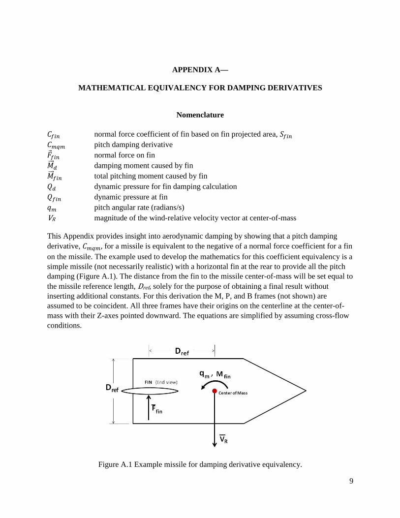
𝐶𝑓𝑖𝑛 normal force coefficient of fin based on fin projected area, 𝑆𝑓𝑖𝑛 𝐶𝑚𝑞𝑚 pitch damping derivative �⃗�𝑓𝑖𝑛 normal force on fin 𝑀��⃗ 𝑑 damping moment caused by fin 𝑀��⃗ 𝑓𝑖𝑛 total pitching moment caused by fin 𝑄𝑑 dynamic pressure for fin damping calculation 𝑄𝑓𝑖𝑛 dynamic pressure at fin 𝑞𝑚 pitch angular rate (radians/s) VR magnitude of the wind-relative velocity vector at center-of-mass This Appendix provides insight into aerodynamic damping by showing that a pitch damping derivative, 𝐶𝑚𝑞𝑚, for a missile is equivalent to the negative of a normal force coefficient for a fin on the missile. The example used to develop the mathematics for this coefficient equivalency is a simple missile (not necessarily realistic) with a horizontal fin at the rear to provide all the pitch damping (Figure A.1). The distance from the fin to the missile center-of-mass will be set equal to the missile reference length, Dref, solely for the purpose of obtaining a final result without inserting additional constants. For this derivation the M, P, and B frames (not shown) are assumed to be coincident. All three frames have their origins on the centerline at the center-of-mass with their Z-axes pointed downward. The equations are simplified by assuming cross-flow conditions.
Figure A.1 Example missile for damping derivative equivalency.
10
By inspection of Figure A.1, the dynamic pressure at the fin is:
𝑄𝑓𝑖𝑛 = 12 𝜌 �𝑉𝑅2 + 2𝑉𝑅 𝐷𝑟𝑒𝑓 𝑞𝑚 + 𝐷𝑟𝑒𝑓2 𝑞𝑚2 � (𝐴. 1)
The magnitude of the third term in parentheses in equation (A.1) is typically less than 1% of the magnitude of the second term, so the third term will be ignored. The fin dynamic pressure now becomes:
𝑄𝑓𝑖𝑛 = 12 𝜌 �𝑉𝑅2 + 2 𝑉𝑅 𝐷𝑟𝑒𝑓 𝑞𝑚 � (𝐴. 2)
The fin normal force is simply:
𝐹𝑓𝑖𝑛 = 𝑄𝑓𝑖𝑛 𝐶𝑓𝑖𝑛 𝑆𝑓𝑖𝑛 (𝐴. 3)
where 𝑆𝑓𝑖𝑛 is the fin projected area and 𝐶𝑓𝑖𝑛 is the normal force coefficient of the fin based on the fin projected area. The total pitching moment caused by the fin is the negative of the fin normal force times the moment arm, 𝐷𝑟𝑒𝑓, as follows:
𝑀𝑓𝑖𝑛 = − 𝑄𝑓𝑖𝑛 𝐶𝑓𝑖𝑛 𝑆𝑓𝑖𝑛 𝐷𝑟𝑒𝑓 (𝐴. 4)
It will now be assumed that the fin projected area, 𝑆𝑓𝑖𝑛, is 1/4 of the missile reference area, 𝑆𝑟𝑒𝑓. (This assumption permits the final result to be obtained without inserting additional constants). Plugging this 1/4 fin area relationship into equation (A.4) produces:
𝑀𝑓𝑖𝑛 = − 14𝑄𝑓𝑖𝑛 𝐶𝑓𝑖𝑛 𝑆𝑟𝑒𝑓 𝐷𝑟𝑒𝑓 (𝐴. 5)
Going back to equation (A.1) for the dynamic pressure at the fin, the first term inside the parentheses is for the static moment, so only the second term is needed for damping calculations. The dynamic pressure to be used for fin damping is therefore:
𝑄𝑑 = 𝜌 𝑉𝑅 𝐷𝑟𝑒𝑓 𝑞𝑚 (𝐴. 6)
Substituting the right side of equation (A.6) for the 𝑄𝑓𝑖𝑛 term in equation (A.5) produces the fin damping moment as follows:
𝑀𝑑 = − 14 𝜌 𝑉𝑅 𝑞𝑚 𝐶𝑓𝑖𝑛 𝑆𝑟𝑒𝑓 𝐷𝑟𝑒𝑓2 (𝐴. 7)

11
The fin damping moment will now be expressed in a generic form using the following traditional damping moment coefficient equation:
𝑀𝑑 = 12 𝜌 𝑉𝑅2 𝑆𝑟𝑒𝑓 𝐷𝑟𝑒𝑓 𝐶𝑚𝑚𝑑 (𝐴. 8)
where 𝐶𝑚𝑚𝑑 is the pitch damping moment coefficient, which represents the change in the pitching moment coefficient caused by fin damping in this example. Combining equations (A.7) and (A.8) to eliminate 𝑀𝑑 produces the following equation that shows a linear relationship between 𝐶𝑚𝑚𝑑 and 𝑞𝑚 for the simple example chosen:
𝐶𝑚𝑚𝑑 = − 𝑞𝑚𝐷𝑟𝑒𝑓
2𝑉𝑅 ∙ 𝐶𝑓𝑖𝑛 (𝐴. 9)
𝐶𝑚𝑚𝑑 can also be expressed, in a general sense, as the following partial differential equation:
𝐶𝑚𝑚𝑑 = 𝜕𝐶𝑚𝑚
𝜕𝑞𝑚∙ 𝑞𝑚 (𝐴. 10)
Combining equations (A.9) and (A.10) to eliminate 𝐶𝑚𝑚𝑑, and then solving for the normal force coefficient of the fin, 𝐶𝑓𝑖𝑛, produces the following relationship:
𝐶𝑓𝑖𝑛 = − 𝜕𝐶𝑚𝑚
𝜕 �𝑞𝑚 𝐷𝑟𝑒𝑓
2 𝑉𝑅�
(𝐴. 11)
The traditional equation that defines the pitch damping derivative, 𝐶𝑚𝑞𝑚, is:
𝐶𝑚𝑞𝑚 = 𝜕𝐶𝑚𝑚
𝜕 �𝑞𝑚 𝐷𝑟𝑒𝑓
2 𝑉𝑅�
(𝐴. 12)
The identical expressions on the right side of equations (A.11) and (A.12) illustrate that for purposes of missile damping, a pitch damping derivative is equivalent to the negative of a normal force coefficient for a horizontal fin.
12
APPENDIX B—
PITCH DAMPING MOMENT FOR A CROSS-FLOW CYLINDER
Nomenclature
C cylinder cross-flow drag coefficient (The reference area for C is always the cylinder cross-flow projected area being analyzed, whether that area is an incremental area or the total area; C is assumed to not vary with the size of the cylinder or the size of any incremental projected area) 𝑐𝑔 distance from center-of-mass to forward end of cylinder, expressed as a fraction
of cylinder length (forward end is right side of cylinder in figure B.1) D cylinder diameter (total projected area in cross-flow conditions = L D) dx incremental distance along cylinder length (incremental projected area = dx D) �⃗�𝑖 incremental aerodynamic force on incremental projected area (�⃗�𝑖 = Q C dx D) L cylinder length 𝑀��⃗ 𝑑 total damping moment about center-of-mass 𝑀��⃗ 𝑖 incremental moment about center-of-mass Q dynamic pressure at incremental projected area 𝑞𝑚 pitch angular rate (radians/s) 𝑉𝑅 magnitude of the wind-relative velocity vector at center-of-mass X distance from center-of-mass to incremental projected area (positive forward) This Appendix provides additional insight into aerodynamic damping by presenting a derivation of the pitch damping moment for a cylinder in cross-flow conditions (Figure B.1). The effects of the longitudinal location of the center-of-mass are included and are very important. The cylinder is assumed to have the aerodynamic properties of an infinite cylinder (no end flow). For this derivation, the M, P and B frames (not shown) are assumed to be coincident. All three frames have their origins on the centerline at the center-of-mass with their Z-axes pointed downward.
Figure B.1 Cross-flow cylinder.

13
By inspection of Figure B.1, the dynamic pressure at the incremental projected area is:
𝑄 = 12𝜌
(𝑉𝑅2 − 2𝑉𝑅𝑞𝑚𝑋 + 𝑞𝑚2 𝑋2) (𝐵. 1)
Typically, the magnitude of the third term in parentheses in equation (B.1) is approximately 1% of the magnitude of the second term, so the third term will be ignored. The dynamic pressure now becomes:
𝑄 = 12𝜌
(𝑉𝑅2 − 2𝑉𝑅𝑞𝑚𝑋) (𝐵. 2)
The incremental aerodynamic force on the incremental projected area is:
𝐹𝑖 = 12𝜌
(𝑉𝑅2 − 2𝑉𝑅𝑞𝑚𝑋) 𝐶 𝐷 𝑑𝑥 (𝐵. 3)
The incremental moment about the center-of-mass caused by the incremental aerodynamic force is:
𝑀𝑖 = 12𝜌
(𝑉𝑅2 − 2𝑉𝑅𝑞𝑚𝑋) 𝐶 𝑋 𝐷 𝑑𝑥 (𝐵. 4)
The first term in parentheses of equation (B.4) is for calculating the incremental static moment and is not needed in this derivation. The second term, −2𝑉𝑅𝑞𝑚𝑋 , is the term of interest in this example because it determines the incremental damping moment, 𝑀𝑑𝑖, as follows:
𝑀𝑑𝑖 = −𝜌𝑉𝑅𝑞𝑚 𝐶 𝑋2 𝐷 𝑑𝑥 (𝐵. 5)
Integrating equation (B.5) from the aft end to the forward end of the cylinder (from left to right in Figure B.1) produces the following equation for the total damping moment about the center-of-mass:
𝑀𝑑 = −13𝜌𝑉𝑅𝑞𝑚 𝐶 𝐷 𝐿3(1 − 3𝑐𝑔 + 3𝑐𝑔2) (𝐵. 6)
Equation (B.6) for the total damping moment is the final result for this example, and it shows the significant sensitivity of pitch damping to the longitudinal center-of-mass location and to the cylinder length.

xi
REPORT DOCUMENTATION PAGE Form ApprovedOMB No. 0704-0188
The public reporting burden for this collection of information is estimated to average 1 hour per response, including the time for reviewing instructions, searching existing data sources, gathering and maintaining the data needed, and completing and reviewing the collection of information. Send comments regarding this burden estimate or any other aspect of this collection of information, including suggestions for reducing this burden, to Department of Defense, Washington Headquarters Services, Directorate for Information Operation and Reports (0704-0188), 1215 Jefferson Davis Highway, Suite 1204, Arlington, VA 22202-4302. Respondents should be aware that notwithstanding any other provision of law, no person shall be subject to any penalty for failing to comply with a collection of information if it does not display a currently valid OMB control number.PLEASE DO NOT RETURN YOUR FORM TO THE ABOVE ADDRESS.
1. REPORT DATE (DD-MM-YYYY) 2. REPORT TYPE 3. DATES COVERED (From - To)
4. TITLE AND SUBTITLE 5a. CONTRACT NUMBER
5b. GRANT NUMBER
5c. PROGRAM ELEMENT NUMBER
6. AUTHOR(S) 5d. PROJECT NUMBER
5e. TASK NUMBER
5f. WORK UNIT NUMBER
7. PERFORMING ORGANIZATION NAME(S) AND ADDRESS(ES) 8. PERFORMING ORGANIZATION REPORT NUMBER
9. SPONSORING/MONITORING AGENCY NAME(S) AND ADDRESS(ES) 10. SPONSORING/MONITOR’S ACRONYM(S)
11. SPONSORING/MONITORING REPORT NUMBER
12. DISTRIBUTION/AVAILABILITY STATEMENT
13. SUPPLEMENTARY NOTES
14. ABSTRACT
15. SUBJECT TERMS
16. SECURITY CLASSIFICATION OF:a. REPORT b. ABSTRACT c. THIS PAGE
17. LIMITATION OF ABSTRACT 18. NUMBER OF PAGES
19a. NAME OF RESPONSIBLE PERSON
19b. TELEPHONE NUMBER (Include area code)
Standard Form 298 (Rev. 8-98)Prescribed by ANSI Std. Z39-18
Missile Aerodynamics for Ascent and Re-entry
G.L. Watts* and J.W. McCarter**
George C. Marshall Space Flight Center, Huntsville, AL 35812Jacobs ESSSA Group, Huntsville, AL
National Aeronautics and Space AdministrationWashington, DC 20546–0001
Unclassified-UnlimitedSubject Category 02Availability: NASA CASI (443–757–5802)
Prepared for the Spacecraft & Vehicle Systems Dept., Engineering DirectorateCOTR: Kimball Y. Ibrahim*Qualis Corporation **DESE Research
M–1351
NNM12AA41C
October 2011–September 2012Contractor Report
NASA/CR—2012–217475
missile aerodynamics, aerodynamic damping, damping derivatives, missile coordinate frame, missile re-entry, 6 degrees-of-freedom
01–11–2012
UU 28U U U
Aerodynamic force and moment equations are developed for 6-DOF missile simulations of both the ascent phase of flight and a tumbling re-entry. The missile coordinate frame (M frame) and a frame paral-lel to the M frame were used for formulating the aerodynamic equations. The missile configuration chosen as an example is a cylinder with fixed fins and a nose cone. The equations include both the static aero-dynamic coefficients and the aerodynamic damping derivatives. The inclusion of aerodynamic damping is essential for simulating a tumbling re-entry. Appended information provides insight into aerodynamic damping.
STI Help Desk at email: [email protected]
STI Help Desk at: 443–757–5802


NASA/CR—2012–
Missile Aerodynamics for Ascent and Re-entryG.L. WattsJacobs ESSA Group,Qualis Corporation, Huntsville, Alabama
J.W. McCarterJacobs ESSA Group, DESE Research, Huntsville, Alabama
October 2012
National Aeronautics andSpace AdministrationIS20George C. Marshall Space Flight CenterHuntsville, Alabama 35812
Prepared for Marshall Space Flight Centerunder Contract NNM12AA41C


![AERODYNAMICS OF A ROLLING AIRFRAME MISSILE …fabricated model of a Rolling Airframe Missile. The Applied Physics Laboratory planned] and conducted the testing for the Navy under APL](https://static.fdocuments.in/doc/165x107/5e957f5303049060c249f11c/aerodynamics-of-a-rolling-airframe-missile-fabricated-model-of-a-rolling-airframe.jpg)
