MISO Guideline for IEEE Std 1547 v2 12-16-2019 Guideline for IEEE Std 1547388042.pdf · 0,62...
42
MISO Guideline for IEEE Std 1547-2018 Implementation Recommendations on Requirements Impacting Transmission Systems November 2019
Transcript of MISO Guideline for IEEE Std 1547 v2 12-16-2019 Guideline for IEEE Std 1547388042.pdf · 0,62...

MISO Guideline for IEEE Std 1547-2018 Implementation
Recommendations on Requirements Impacting Transmission Systems
November 2019

MISO Guideline for IEEE Std 1547-2018 Implementation ii
Acknowledgments This guideline is made possible by the help and support provided by the Electric Power Research Institute (EPRI) through the “Navigating DER Interconnection Standards and Practices” project (SPN 3002012048).
MISO would also like to thank all stakeholders that supported the drafting of these recommendations.
MISO Guideline for IEEE Std 1547-2018 Implementation iii
Disclaimer MISO does not have jurisdiction over distribution system interconnections. Utilities following this guideline is greatly encouraged but not mandatory.
This guideline does not provide recommendations on all requirements in IEEE Std 1547-2018. It only provides recommendations on requirements that impact the transmission system reliability.

MISO Guideline for IEEE Std 1547-2018 Implementation iv
CONTENTS ACKNOWLEDGMENTS ..................................................................................................................................................................... II
INTRODUCTION ............................................................................................................................................................................... 11 IEEE Std 1547™-2018 ............................................................................................................................................................. 11 Objective and Scope of this Reliability Guideline.......................................................................................................... 11 Jurisdictional Considerations ............................................................................................................................................... 12 Coordination between Distribution and Transmission Planning ........................................................................... 13
Drivers .................................................................................................................................................................................. 13 Balancing Distribution and Transmission Needs .................................................................................................. 13 Settings of Distribution Utility Equipment .............................................................................................................. 14
POTENTIAL IMPACTS FROM DER ON BULK POWER SYSTEM RELIABILITY .......................................................... 16
RECOMMENDED ADOPTION OF CLAUSE 1 – OVERVIEW ............................................................................................ 19 Part 1 – Ride-through performance category assignment ........................................................................................ 19
Clause 1.4 – General Remarks ..................................................................................................................................... 19 Recommendation #1 ................................................................................................................................................................ 20
RECOMMENDED ADOPTION OF CLAUSE 6 – RESPONSE TO AREA EPS ABNORMAL CONDITIONS ...................................................................................................................................................................................... 21
Part 1 – Response to Abnormal Voltage Conditions .................................................................................................... 21 Clause 6.4.1 – Mandatory Voltage Tripping Requirements .............................................................................. 21
Recommendation #2 ................................................................................................................................................................ 22 Recommendation #3a.............................................................................................................................................................. 22 Recommendation #3b (subject to approval of P1547a amendment) ................................................................... 23 Recommendation #4 ................................................................................................................................................................ 23
Clause 6.4.2 – Voltage disturbance ride-through performance requirements .......................................... 24 Recommendation #5a.............................................................................................................................................................. 24 Recommendation #5b ............................................................................................................................................................. 25 Recommendation #6 ................................................................................................................................................................ 27 Recommendation #7 ................................................................................................................................................................ 28 Part 2 – Response to Abnormal Frequency Conditions .............................................................................................. 29
Clause 6.5.1 – Mandatory Frequency Tripping Requirements ........................................................................ 29 Recommendation #8 ................................................................................................................................................................ 29 Recommendation #9 ................................................................................................................................................................ 29
Clause 6.5.2 – Frequency disturbance ride-through requirements ............................................................... 30 Recommendation #10 ............................................................................................................................................................. 30 Recommendation #11 ............................................................................................................................................................. 31 Recommendation #12 ............................................................................................................................................................. 32
RECOMMENDED ADOPTION OF CLAUSE 6 – FREQUENCY DROOP AND INERTIAL RESPONSE ................. 32 Clause 6.5.2.7.2 – Frequency-Droop (Frequency/Power) Operation ........................................................... 32
Recommendation #13 ............................................................................................................................................................. 33 Clause 6.5.2.8 – Inertial Response .............................................................................................................................. 33
CLAUSES 4.10 – ENTER SERVICE AND CLAUSE AND 6.6 – RETURN TO SERVICE AFTER TRIP ....................... 35 Clause 4.10.2 – Enter Service / Clause 6.6 – Return to Service After Trip .......................................................... 35 Recommendation #14 ............................................................................................................................................................. 35 Clause 4.10.3 – Performance during entering service ................................................................................................ 36 Recommendation #15 ............................................................................................................................................................. 36
REFERENCES ...................................................................................................................................................................................... 37

MISO Guideline for IEEE Std 1547-2018 Implementation v
APPENDIX ............................................................................................................................................................................................ 39


MISO Guideline for IEEE Std 1547-2018 Implementation vii
LIST OF FIGURES Figure 1. Increasing need for T&D Coordination regarding new DER capabilities and their
utilization by choosing reliable functional settings .................................................................................. 14
Figure 2: Examples for distribution utility equipment that is not in the scope of IEEE Std 1547™-2018 but may impact BPS reliability in areas with increasing DER deployment. ........... 15
Figure 3. DER response to abnormal voltages and voltage ride-through requirements for DER of abnormal operating performance Category II ............................................................................. 25
Figure 4. DER response to abnormal voltages and voltage ride-through requirements for DER of abnormal operating performance Category III ........................................................................... 26
Figure 5. DER default response to abnormal frequencies and frequency ride-through requirements for DER of abnormal operating performance Category I, Category II, and Category III ............................................................................................................................................................. 30


MISO Guideline for IEEE Std 1547-2018 Implementation ix
LIST OF TABLES Table 1. MISO recommendations for adopting DER performance categories ....................................... 20
Table 2. Synchronous generation voltage trip settings for Category I ...................................................... 22
Table 3. Inverter-based generation and storage voltage trip settings for Category II ........................ 22
Table 4. Inverter-based generation and storage voltage trip settings for Category III (Amendment) ......................................................................................................................................................... 23
Table 5. Voltage ride-through requirements for consecutive temporary voltage disturbances caused by unsuccessful reclosing for DER of abnormal operating performance Category I, Category II, and Category III ........................................................................... 28
Table 6. Recommended frequency trip settings for DER of any type ........................................................ 29
Table 7. Recommended ROCOF Ride-Through Performance ..................................................................... 31
Table 8. Parameters of frequency-droop (frequency-power) operation for DER of abnormal operating performance Category I, Category II, and Category III ................................... 33
Table 9. Enter service criteria for DER of Category I, Category II, and Category III ............................ 35


MISO Guideline for IEEE Std 1547-2018 Implementation 11
Introduction Distributed Energy Resources (DER) is defined for the purpose of this document as resources connected at typical primary or secondary distribution voltage levels. DER may be retail-scale DER (R-DER) like roof-top solar and utility-scale DER (U-DER) like community solar farms and small wind farms. DER also includes behind-the-meter (BTM) and utility-scale electric storage as well as less common distribution-connected resources like landfill gas and combined heat and power plants. DER does not refer to dispersed energy resources that are connected to the bulk power system like large-scale wind or solar plants. For inverter-based resources connected to the bulk power system, the IEEE Standards Association’s P2800 Working Group is currently drafting standard technical minimum requirements which will be published in the coming years.
IEEE Std 1547™-2018 IEEE Std 1547™-2018, IEEE Standard for Interconnecting Distributed Resources with Electric Power Systems, (abbreviated IEEE 1547) [1] is a newly published standard for DER interconnection and interoperability requirements. It is a technology-neutral, voluntary IEEE standard that has been highly vetted by a large group of stakeholders with the aim to harmonize technical interconnection performance capability requirements and functional specifications for the growing installations of distributed generation and energy storage systems.
Former versions of IEEE 1547 were designed for low DER penetration levels and did not consider the potential aggregate regional impact of DER on the bulk power system. In 2018, IEEE 1547 added new requirements regarding voltage and frequency ride-through capability, to help the reliability of the transmission system. As a voluntary industry standard, these new IEEE 1547 requirements will not enter into effect until the standard is adopted by the Authority Governing Interconnection Requirements (AGIR), which can be the responsible distribution provider, electric cooperative governing board, or a state’s public utility commission. For further reading and publicly available training modules on IEEE 1547, refer to [2], [3], [4], and [5].
Objective and Scope of this Reliability Guideline With the addition of new requirements regarding voltage and frequency ride-through capability, IEEE 1547 also includes provisions for coordination with regional reliability coordinators. MISO is the regional reliability coordinator in the in the MISO.
To help facilitate such a coordination in a regional level, MISO initiated a stakeholder collaboration process with MISO states and the transmission and distribution utilities and experts in 2019 [6] to develop this reliability guideline for non-jurisdictional distribution-connected generation and storage resources to provide:

MISO Guideline for IEEE Std 1547-2018 Implementation 12
A regional preferred choice of abnormal performance category assignment for voltage and frequency ride-through, and
A regional preferred utility-required profile for functional settings, including voltage and frequency trip setting thresholds and clearing times, frequency-droop parameters, and return to service after trip / enter service criteria.
For reference, PJM also worked with stakeholders since 2018 [7] and issued a draft reliability guideline for ride-through performance of DER in August/September 2019. ISO NE published an interim guideline (called “source requirement document” at that time) in February 2018 [9] and is currently working on updating that guideline with support from the Massachusetts Technical Standards Review Group (MA TSRG) [10].
Jurisdictional Considerations MISO does not have jurisdiction over the interconnection of distributed energy resources that are connected to distribution grids in the MISO region. They fall under connected distribution provider’s jurisdiction and, as applicable, its state’s public utility commission or electric cooperatives governing board. This guideline provides MISO stakeholder’s general preference which covers the general need of both transmission and distribution systems. The adoption of this guideline is encouraged but not mandatory.
MISO Guideline for IEEE Std 1547-2018 Implementation 13
Coordination between Distribution and Transmission Planning
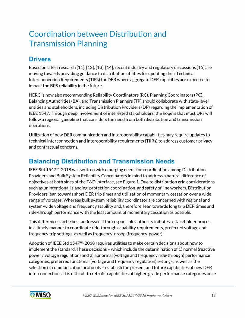
Drivers Based on latest research [11], [12], [13], [14], recent industry and regulatory discussions [15] are moving towards providing guidance to distribution utilities for updating their Technical Interconnection Requirements (TIRs) for DER where aggregate DER capacities are expected to impact the BPS reliability in the future.
NERC is now also recommending Reliability Coordinators (RC), Planning Coordinators (PC), Balancing Authorities (BA), and Transmission Planners (TP) should collaborate with state-level entities and stakeholders, including Distribution Providers (DP) regarding the implementation of IEEE 1547. Through deep involvement of interested stakeholders, the hope is that most DPs will follow a regional guideline that considers the need from both distribution and transmission operations.
Utilization of new DER communication and interoperability capabilities may require updates to technical interconnection and interoperability requirements (TIIRs) to address customer privacy and contractual concerns.
Balancing Distribution and Transmission Needs IEEE Std 1547™-2018 was written with emerging needs for coordination among Distribution Providers and Bulk System Reliability Coordinators in mind to address a natural difference of objectives at both sides of the T&D interface, see Figure 1. Due to distribution grid considerations such as unintentional islanding, protection coordination, and safety of line workers, Distribution Providers lean towards short DER trip times and utilization of momentary cessation over a wide range of voltages. Whereas bulk system reliability coordinator are concerned with regional and system-wide voltage and frequency stability and, therefore, lean towards long trip DER times and ride-through performance with the least amount of momentary cessation as possible.
This difference can be best addressed if the responsible authority initiates a stakeholder process in a timely manner to coordinate ride-through capability requirements, preferred voltage and frequency trip settings, as well as frequency-droop (frequency-power).
Adoption of IEEE Std 1547™-2018 requires utilities to make certain decisions about how to implement the standard. These decisions – which include the determination of 1) normal (reactive power / voltage regulation) and 2) abnormal (voltage and frequency ride-through) performance categories, preferred functional (voltage and frequency regulation) settings; as well as the selection of communication protocols – establish the present and future capabilities of new DER interconnections. It is difficult to retrofit capabilities of higher-grade performance categories once

MISO Guideline for IEEE Std 1547-2018 Implementation 14
these decisions are made. The rationale for making these decisions early on is to ensure that new DER interconnections can meet standardized advanced performance and functional capabilities even if some of these may not be utilized until they become necessary at a future date.
In regard to functional settings, IEEE Std 1547™-2018 specifies default values. If stakeholders decide these are not appropriate for certain classes of DER (technology, size, use-case, etc.), then preferred settings may be specified for these DER classes. For DERs that are not integrated into a DER management system (DERMS) which requires the presence of communications to DERs, retroactive changes of functional settings may be difficult as they could require manual action on site. Decisions relating to abnormal performance category assignment and specification of preferred settings for any active power related functions (e.g. frequency-droop [frequency-power] and voltage-active power) should be coordinated with the Reliability Coordinator.
Figure 1. Increasing need for T&D Coordination regarding new DER capabilities and their utilization by choosing reliable functional settings
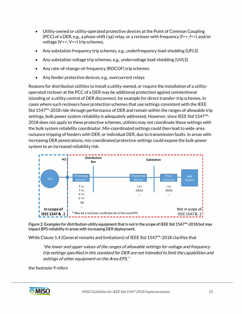
Settings of Distribution Utility Equipment A need for coordination between distribution utilities and the reliability coordinator (here: MISO) that has received little attention to date relates to protection settings of distribution utility-owned or utility-operated equipment that is not in the scope of IEEE Std 1547™-2018. This equipment may still impact bulk power system reliability in areas with increasing DER deployment because it may trip DER that would otherwise ride through voltage and frequency disturbances. Figure 2: Examples for distribution utility equipment that is not in the scope of IEEE Std 1547™-2018 but may impact BPS reliability in areas with increasing DER deployment. shows examples for such equipment:
MISO Guideline for IEEE Std 1547-2018 Implementation 15
Utility-owned or utility-operated protective devices at the Point of Common Coupling (PCC) of a DER, e.g., a phase-shift () relay, or a recloser with frequency (f>>, f<<) and/or voltage (V>>, V<<) trip schemes.
Any substation frequency trip schemes, e.g., underfrequency load-shedding (UFLS)
Any substation voltage trip schemes, e.g., undervoltage load-shedding (UVLS)
Any rate-of-change-of-frequency (ROCOF) trip schemes
Any feeder protective devices, e.g., overcurrent relays
Reasons for distribution utilities to install a utility-owned, or require the installation of a utility-operated recloser at the PCC of a DER may be additional protection against unintentional islanding or a utility control of DER disconnect, for example for direct transfer-trip schemes. In cases where such reclosers have protection schemes that use settings consistent with the IEEE Std 1547™-2018 ride-through performance of DER and remain within the ranges of allowable trip settings, bulk power system reliability is adequately addressed. However, since IEEE Std 1547™-2018 does not apply to these protective schemes, utilities may not coordinate these settings with the bulk system reliability coordinator. Mis-coordinated settings could then lead to wide-area nuisance tripping of feeders with DER, or individual DER, due to transmission faults. In areas with increasing DER penetrations, mis-coordinated protective settings could expose the bulk power system to an increased reliability risk.
DER
Distribution Bus Substation
Protective Device
Protective Device*
f >>f <<V >>V <<…
Not in scope of IEEE 1547 & .1
PCC
* May be a recloser, could also be in the Local EPS
Bulk System
Prot. Schemes
In scope of IEEE 1547 & .1
I >>f/t
…
I >>f/t
…
Figure 2: Examples for distribution utility equipment that is not in the scope of IEEE Std 1547™-2018 but may impact BPS reliability in areas with increasing DER deployment.
While Clause 1.4 (General remarks and limitations) of IEEE Std 1547™-2018 clarifies that
“the lower and upper values of the ranges of allowable settings for voltage and frequency trip settings specified in this standard for DER are not intended to limit the capabilities and settings of other equipment on the Area EPS,”
the footnote 9 refers
MISO Guideline for IEEE Std 1547-2018 Implementation 16
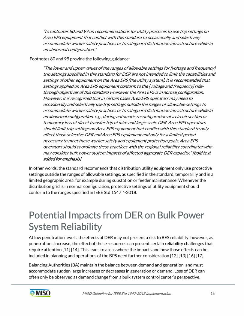
“to footnotes 80 and 99 on recommendations for utility practices to use trip settings on Area EPS equipment that conflict with this standard to occasionally and selectively accommodate worker safety practices or to safeguard distribution infrastructure while in an abnormal configuration.”
Footnotes 80 and 99 provide the following guidance:
“The lower and upper values of the ranges of allowable settings for [voltage and frequency] trip settings specified in this standard for DER are not intended to limit the capabilities and settings of other equipment on the Area EPS [the utility system]. It is recommended that settings applied on Area EPS equipment conform to the [voltage and frequency] ride-through objectives of this standard whenever the Area EPS is in normal configuration. However, it is recognized that in certain cases Area EPS operators may need to occasionally and selectively use trip settings outside the ranges of allowable settings to accommodate worker safety practices or to safeguard distribution infrastructure while in an abnormal configuration, e.g., during automatic reconfiguration of a circuit section or temporary loss of direct transfer trip of mid- and large-scale DER. Area EPS operators should limit trip settings on Area EPS equipment that conflict with this standard to only affect those selective DER and Area EPS equipment and only for a limited period necessary to meet these worker safety and equipment protection goals. Area EPS operators should coordinate these practices with the regional reliability coordinator who may consider bulk power system impacts of affected aggregate DER capacity.” [bold text added for emphasis]
In other words, the standard recommends that distribution utility equipment only use protective settings outside the ranges of allowable settings, as specified in the standard, temporarily and in a limited geographic area, for example during substation or feeder maintenance. Whenever the distribution grid is in normal configuration, protective settings of utility equipment should conform to the ranges specified in IEEE Std 1547™-2018.
Potential Impacts from DER on Bulk Power System Reliability At low penetration levels, the effects of DER may not present a risk to BES reliability; however, as penetrations increase, the effect of these resources can present certain reliability challenges that require attention [11] [14]. This leads to areas where the impacts and how those effects can be included in planning and operations of the BPS need further consideration [12] [13] [16] [17].
Balancing Authorities (BA) maintain the balance between demand and generation, and must accommodate sudden large increases or decreases in generation or demand. Loss of DER can often only be observed as demand change from a bulk system control center’s perspective.

MISO Guideline for IEEE Std 1547-2018 Implementation 17
BPS-connected generation resources provide telemetry, which provides the BA with real-time visibility into their performance, as well as meeting other requirements to ride through disturbances, provide reliability services, and have active power management capability to respond to dispatch or automatic generation control (AGC) signals. Large-scale resources that utilize variable energy resources (e.g., solar and wind) should also meet these requirements.
NERC has taken a detailed look at the potential impacts of DER on the BPS in the form of solar photovoltaic systems (PVs) on the distribution system. This work was published in the NERC Integrating Variable Generation Task Force Task (IVGTF) 1-7 report titled “Performance of Distributed Energy Resources During and After System Disturbance: Voltage and Frequency Ride-Through Requirements in December 2013” [18].
IVGTF stated that a large amount of distribution-connected generation may have significant effect on the reliability of the BPS. Of particular concern was the lack of disturbance tolerance, which entails voltage ride through (VRT) and frequency ride through (FRT) capability. Tight mandatory trip limits coupled with lack of ride through capability results in conditions where during instances when the grid frequency or voltage are already out of balance, the DER is required to trip offline. When viewed in aggregate, multiple DER units can scale up to become a very large resource. For example, in 2016, California Independent System Operator (CAISO) stated there were 4,900 MW of DER in its Balancing Authority. In response to their concerns about DER, the Public Utility Commission of California adopted CA rule 21, which identified and implemented many of the functions that are now included in IEEE 1547-2018, and mandated that all solar PV DER installed starting on September 9, 2017 use smart inverters to help these issues.
The capabilities of VER are evolving rapidly, so there are a number of emerging topics that are not within the scope of this report. There is a clear gap between the DER owners and manufactures and their focus on improving local pricing and efficiency compared to supporting the reliability of the grid, unless that support is required or incentivized. Industry will continue monitoring and participating in the ongoing evolution of capabilities and how such capabilities should be incorporated into future planning efforts and operation of the BPS.


MISO Guideline for IEEE Std 1547-2018 Implementation 19
Recommended Adoption of Clause 1 – Overview
Part 1 – Ride-through performance category assignment
Clause 1.4 – General Remarks The IEEE Std 1547-2018 requires DER to ride-through under abnormal conditions with widened Mandatory Tripping Requirements to improve support of the BPS. These ride-through capabilities ensure that DER keep their output during abnormal conditions to help the BPS recover to normal operation. In that sense, DER should not trip offline when voltage and frequency are outside of normal conditions. The IEEE Std 1547-2018 establishes different categories according to the ride-through capabilities. These categories are defined as follows:
Category I
This is a level of compliance compatible with most Bulk Power Systems (BPS) needs, and therefore feasible for all DER technologies to achieve. Category I ride-through performance is not capable of achieving reliable operations under high levels of DER penetration. Therefore, only limited resources should be allowed under this category without causing a negative impact for the system reliability.
Category II
Category II performance covers all BPS reliability needs and coordinates with the existing NERC Standard PRC-024-2, developed to avoid adverse tripping of bulk system generators during system disturbances and are attainable by inverter-based systems.
Category III
Category III provides the highest disturbance ride-through capabilities, which are attainable by inverter-based systems where there are expected high levels of DER penetration or high variability in output, or where momentary cessation requirements are seen as a desirable solution for coordinating with distribution system protection and safety. It has an enhanced level of robustness where DER operation becomes important for the benefit of distribution system.

MISO Guideline for IEEE Std 1547-2018 Implementation 20
Recommendation #1 MISO strongly recommends following the ride-through performances according to IEEE Std 1547-2018 as shown in Table 1. MISO strongly recommends to be notified of any exceptions at distribution company level.
Table 1. MISO recommendations for adopting DER performance categories
Technology Category Comments
Synchronous generation
I Recommended minimum capabilities of Category I from IEEE Std 1547-2018.
Inverter-based generation and storage
III when amended or II
Preferred: minimum capabilities of Category III as shown in Figure 4. DER response to abnormal voltages and voltage ride-through requirements for DER of abnormal operating performance Category III of IEEE Std 1547a-2020. (adopted if published)
Alternative: minimum capabilities of Category II with modifications as
shown in Figure 3. DER response to abnormal voltages and voltage ride-through requirements for DER of abnormal operating performance Category II from the current IEEE Std 1547-2018.
MISO recommendations — Recommended: Specifications are expected to have medium bulk system reliability impact. Strongly recommended: Specifications are expected to have a high bulk system reliability impact.

MISO Guideline for IEEE Std 1547-2018 Implementation 21
Recommended Adoption of Clause 6 – Response to Area EPS Abnormal Conditions
Part 1 – Response to Abnormal Voltage Conditions
Clause 6.4.1 – Mandatory Voltage Tripping Requirements When any applicable voltage is less than an undervoltage threshold, or greater than an overvoltage threshold, it is recommended that the DER cease to energize the Area EPS and trip within the respective clearing time as indicated. Tripping requirements determines to which extent the ride-through capabilities of the DER are utilized.
Recommendations and comparisons to the default settings from IEEE Std 1547-2018 (2nd ed.) are shown as follows:
Table 2: Voltage trip settings for synchronous generation assigned to Category I Table 3: Voltage trip settings for inverter-based generation and storage assigned to
Category II Table 4: Voltage trip settings for inverter-based generators and storage to Category III
(recommended if the IEEE Std 1547-2018 amendment is revised and published)
MISO Guideline for IEEE Std 1547-2018 Implementation 22
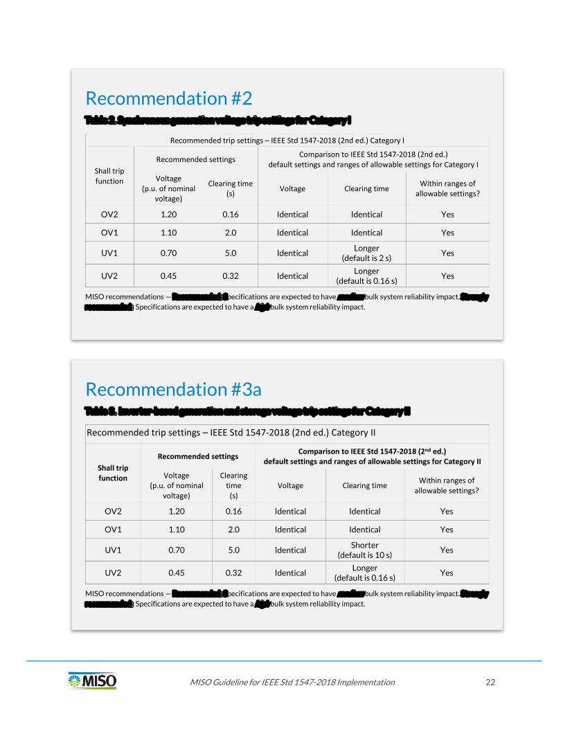
Recommendation #2 Table 2. Synchronous generation voltage trip settings for Category I
Recommended trip settings – IEEE Std 1547-2018 (2nd ed.) Category I
Shall trip function
Recommended settings Comparison to IEEE Std 1547-2018 (2nd ed.)
default settings and ranges of allowable settings for Category I
Voltage (p.u. of nominal
voltage)
Clearing time (s) Voltage Clearing time
Within ranges of allowable settings?
OV2 1.20 0.16 Identical Identical Yes
OV1 1.10 2.0 Identical Identical Yes
UV1 0.70 5.0 Identical Longer
(default is 2 s) Yes
UV2 0.45 0.32 Identical Longer (default is 0.16 s) Yes
MISO recommendations — Recommended: Specifications are expected to have medium bulk system reliability impact. Strongly recommended: Specifications are expected to have a high bulk system reliability impact.
Recommendation #3a Table 3. Inverter-based generation and storage voltage trip settings for Category II
Recommended trip settings – IEEE Std 1547-2018 (2nd ed.) Category II
Shall trip function
Recommended settings Comparison to IEEE Std 1547-2018 (2nd ed.) default settings and ranges of allowable settings for Category II
Voltage (p.u. of nominal
voltage)
Clearing time (s)
Voltage Clearing time Within ranges of
allowable settings?
OV2 1.20 0.16 Identical Identical Yes
OV1 1.10 2.0 Identical Identical Yes
UV1 0.70 5.0 Identical Shorter (default is 10 s) Yes
UV2 0.45 0.32 Identical Longer (default is 0.16 s) Yes
MISO recommendations — Recommended: Specifications are expected to have medium bulk system reliability impact. Strongly recommended: Specifications are expected to have a high bulk system reliability impact.

MISO Guideline for IEEE Std 1547-2018 Implementation 23
In addition, as discussed in the Introduction section, MISO also provides the following recommendation for voltage trip settings for distribution equipment.
Recommendation #3b (subject to approval of P1547a amendment) Table 4. Inverter-based generation and storage voltage trip settings for Category III (Amendment)
Recommended trip settings – IEEE Std 1547a-2020 (Amendment) Category III
Shall trip function
Recommended settings Comparison to IEEE Std 1547-2020 (Amendment) default settings and ranges of allowable settings for Category III
Voltage (p.u. of nominal
voltage)
Clearing time (s)
Voltage Clearing time Within ranges of allowable
settings?
OV2 1.20 0.16 Identical Identical Yes
OV1 1.10 2.0 Identical Shorter
(default is 13 s) Yes
UV1 0.70 5.0 Lower (default is 0.88)
Shorter (default is 21 s)
Yes
UV2 0.45 0.32 Lower (default is 0.50)
Shorter (default is 2 s) Yes
MISO recommendations — Recommended: Specifications are expected to have medium bulk system reliability impact. Strongly recommended: Specifications are expected to have a high bulk system reliability impact.
Recommendation #4 MISO recommends that voltage protective settings of distribution utility equipment coordinates with the ranges specified in IEEE Std 1547™-2018 whenever the distribution grid is in normal configuration. MISO recommends the use of voltage protective settings outside the ranges of allowable settings, as specified in the standard, be limited to temporary use and limited geographic area, for example during substation or feeder maintenance.
MISO recommendations — Recommended: Specifications are expected to have medium bulk system reliability impact. Strongly recommended: Specifications are expected to have a high bulk system reliability impact.

MISO Guideline for IEEE Std 1547-2018 Implementation 24
Clause 6.4.2 – Voltage disturbance ride-through requirements Performance during voltage ride-through should be coordinated with common distribution protection practices to avoid mis-operation of distribution protective relays and automatic reclosing into an energized feeder. Momentary Cessation is a ride-through operating mode for inverter-based generation and storage during which the inverters ceases to feed any current to the grid and has been known as a ride-through mode preferred by distribution utilities. Bulk system planners have raised concerns that Momentary Cessation could have negative impact on bulk system reliability. According to related studies including the most recent one from PJM [14], a voltage threshold for Momentary Cessation of 0.5 p.u. is regarded as mutually acceptable for distribution utilities and MISO.
Recommendation #5a MISO strongly recommends that inverter-based generation and storage assigned to abnormal category II ride through voltage conditions above 0.5 p.u. in Mandatory Operation and for voltage conditions equal to or less than 0.5 p.u. in Momentary Cessation as shown in Figure 3. DER response to abnormal voltages and voltage ride-through requirements for DER of abnormal operating performance Category II. MISO recommends to be notified of any exceptions at distribution company level.
MISO recommendations — Recommended: Specifications are expected to have medium bulk system reliability impact. Strongly recommended: Specifications are expected to have a high bulk system reliability impact.

MISO Guideline for IEEE Std 1547-2018 Implementation 25
Figure 3. DER response to abnormal voltages and voltage ride-through requirements for DER of abnormal operating performance Category II
Recommendation #5b (Subject to approval of P1547 amendment)
If the amendment IEEE P1547a is adopted in 2020, MISO strongly recommends that inverter-based generation and storage perform during low voltage ride-through as specified in abnormal category III as shown in Figure 4. DER response to abnormal voltages and voltage ride-through requirements for DER of abnormal operating performance Category III. MISO recommends to be notified of any exceptions at distribution company level.
MISO recommendations — Recommended: Specifications are expected to have medium bulk system reliability impact. Strongly recommended: Specifications are expected to have a high bulk system reliability impact.

MISO Guideline for IEEE Std 1547-2018 Implementation 26
Figure 4. DER response to abnormal voltages and voltage ride-through requirements for DER of abnormal operating performance Category III

MISO Guideline for IEEE Std 1547-2018 Implementation 27
Clause 6.4.2.2 – Voltage disturbances within continuous operation region
Clause 6.4.2.2 in IEEE Std 1547-2018 states that for voltage perturbations within the continuous operation region of the ride-through curves, DER must remain in operation and continue delivering available active power of magnitude at least as great as its pre-disturbance level, prorated by the per-unit voltage of the least phase voltage if that voltage is less than nominal.
Clause 6.4.2.6 – Dynamic Voltage Support MISO recommends following the upcoming IEEE P1547.2 application guide for Dynamic Voltage Support practices. In the interim period while IEEE P1547.2 is not yet revised and published, more information on dynamic voltage support can be found in EPRI reports 3002011171, 3002013502, 3002009363, and 3002011112. Providing dynamic voltage support may help bulk system prevent legacy DER from tripping and mitigate fault-induced delayed voltage recovery during the post-fault period. However, special care should be taken to avoid mis-coordination between DER ride-through performance and some distribution protection practices and should therefore be limited to the “Mandatory Operation” region of Category II and III. It is also important to remark that dynamic voltage support is not expected to increase the run-on times for islanded DER that use active anti-islanding detection methods.
Clause 6.4.2.7.3 – Transition between performance operating regions for Category III DER As per MISO’s Recommendation 5a (or recommendation 5b if amendment is adopted in 2020), a Momentary Cessation threshold of 0.5 p.u. is strongly recommended for both Category II and III assigned DER to align with common distribution practices and keep certification simple. For MISO, any Momentary Cessation threshold equal to or less than 0.5 p.u. is acceptable.
For utility-scale DER (U-DER) with the Reference Point of Applicability (RPA) being the Point of Common Coupling (PCC), due diligence might have to be taken by the DER developer to adjust the
Recommendation #6 MISO strongly recommends following the voltage disturbances within continuous operation region requirements in Clause 6.4.2.2 of IEEE Std 1547-2018. MISO recommends to be notified of any exceptions at distribution company level.
MISO recommendations — Recommended: Specifications are expected to have medium bulk system reliability impact. Strongly recommended: Specifications are expected to have a high bulk system reliability impact.

MISO Guideline for IEEE Std 1547-2018 Implementation 28
Momentary Cessation threshold to account for the predicted voltage difference between the PCC and the Point of DER Connection (i.e., DER terminals).
Clause 6.4.2.5 – Ride-through of consecutive voltage disturbances Clause 6.4.2.5 defines performance during consecutive voltage disturbances. It states that “the requirements for continued operation (ride-through), or restore output shall apply to multiple consecutive voltage disturbances within a ride-through operating region, for which the voltage range and corresponding cumulative durations are specified in” Tables 14 – 16 of IEEE 1547-2018 for Category I, III, and III DER, respectively. These requirements are subject to the provisions that specify conditions in Table 5 (Table 17 of IEEE 1547-2018) for which a DER may trip.
Table 5. Voltage ride-through requirements for consecutive temporary voltage disturbances caused by unsuccessful reclosing for DER of abnormal operating performance Category I, Category II, and Category III
Col. 1 Col. 2 Col. 3 Col. 4
Category Maximum number of ride-through disturbance sets
Minimum time between successive disturbance sets
(s)
Time window for new count of disturbance sets
(min) I 2 20.0 60 II 2 10.0 60 III 3 5.0 20
Recommendation #7 MISO strongly recommends following the ride-through of consecutive voltage disturbances in Clause 6.4.2.5 of IEEE Std 1547-2018. MISO recommends to be notified of any exceptions at distribution company level.
MISO recommendations — Recommended: Specifications are expected to have medium bulk system reliability impact. Strongly recommended: Specifications are expected to have a high bulk system reliability impact.

MISO Guideline for IEEE Std 1547-2018 Implementation 29
Part 2 – Response to Abnormal Frequency Conditions
Clause 6.5.1 – Mandatory Frequency Tripping Requirements
Recommendation #8 MISO strongly recommends that when the system frequency is in a range given below, and the fundamental-frequency component of voltage on any phase is greater than 30% of nominal, DER of any type shall cease to energize the Area EPS and trip within a clearing time as indicated in Table 6. MISO strongly recommends that no exceptions to these minimum requirements are granted.
Table 6. Recommended frequency trip settings for DER of any type
Recommended trip settings – IEEE Std 1547-2018 (2nd ed.)
Shall trip function
Required settings Comparison to IEEE Std 1547-2018 (2nd ed.) default settings and ranges of allowable settings for Category I, II and III
Frequency (Hz)
Clearing time (s) Voltage Clearing time
Within ranges of allowable settings?
OF2 62.0 0.16 Identical Identical Yes
OF1 61.2 300.0 Identical Identical Yes
UF1 58.5 300.0 Identical Identical Yes
UF2 56.5 0.16 Identical Identical Yes
MISO recommendations — Recommended: Specifications are expected to have medium bulk system reliability impact. Strongly recommended: Specifications are expected to have a high bulk system reliability impact.
Recommendation #9 MISO recommends that frequency protective settings of distribution utility equipment conform to the ranges specified in IEEE Std 1547™-2018 whenever the distribution grid is in normal configuration. MISO recommends the use of frequency protective settings outside the ranges of allowable settings, as specified in the standard, be limited to temporary use and limited geographic area, for example during substation or feeder maintenance.
MISO recommendations — Recommended: Specifications are expected to have medium bulk system reliability impact. Strongly recommended: Specifications are expected to have a high bulk system reliability impact.

MISO Guideline for IEEE Std 1547-2018 Implementation 30
Clause 6.5.2 – Frequency disturbance ride-through requirements
Figure 5. DER default response to abnormal frequencies and frequency ride-through requirements for DER of abnormal operating performance Category I, Category II, and Category III
Clause 6.5.2.5 Rate of change of frequency (ROCOF) ride-through Clause 6.5.2.5 in IEEE 1547-2018 states that within the continuous operation region and ride-through operating regions, DERs (as assigned in Recommendation 1) shall not trip for frequency excursions having a magnitude of rate-of-change-of-frequency (ROCOF) that is less than or equal to the values specified in Table 7 (Table 21 of IEEE 1547-2018).
Recommendation #10 MISO strongly recommends that DER of any type are capable of the unified frequency ride-through requirements specified in IEEE Std 1547-2018 and ride through abnormal frequency conditions as specified in Figure 5. MISO strongly recommends that no exceptions to these minimum requirements are granted.
MISO recommendations — Recommended: Specifications are expected to have medium bulk system reliability impact. Strongly recommended: Specifications are expected to have a high bulk system reliability impact.

MISO Guideline for IEEE Std 1547-2018 Implementation 31
Table 7. Recommended ROCOF Ride-Through Performance
Recommended ROCOF Ride-Through Performance – IEEE Std 1547-2018 (2nd ed.)
Category I Category II Category III
0.5 Hz/s 2.0 Hz/s 3.0 Hz/sec
Clause 6.5.2.6 – Voltage Phase Angle Changes Ride-Through Clause 6.5.2.6 describes the ride-through performance requirements for single-phase and multi-phase DER for sub-cycle-to-cycle phase angle changes (referred to as “phase jump”) often caused by fault events or line switching operations on the distribution system or BPS:
Multi-phase DER shall ride through for positive-sequence phase angle changes within a sub-cycle-to-cycle time frame of the applicable voltage of less than or equal to 20 electrical degrees. In addition, multi-phase DER shall remain in operation for change in the phases angle of individual phases less than 60 electrical degrees, provided that the positive sequence angle change does not exceed the forestated criterion. Single-phase DER shall remain in operation for phase angle changes within a sub-cycle-to-cycle time frame of the applicable voltage of less than or equal to 60 electrical degrees. Active and reactive current oscillations in the post-disturbance period that are positively damped or momentary cessation of the DER having a maximum duration of 0.5 s shall be acceptable in response to phase angle changes.
Recommendation #11 MISO strongly recommends following the rate of change of frequency (ROCOF) ride-through performance in Clause 6.5.2.5 of IEEE Std 1547-2018. MISO recommends to be notified of any exceptions at distribution company level.
MISO recommendations — Recommended: Specifications are expected to have medium bulk system reliability impact. Strongly recommended: Specifications are expected to have a high bulk system reliability impact.

MISO Guideline for IEEE Std 1547-2018 Implementation 32
Recommended adoption of clause 6 – frequency droop and inertial response
Clause 6.5.2.7.2 – Frequency-Droop (Frequency/Power) Operation IEEE Std 1547-2018 requires the capability for the Frequency-Droop (Frequency/Power) function for all DER and does not allow the disabling of this function. Some distribution utilities, however, have raised concerns that this function may prolong run-on times (ROTs) of unintentional island if activated and may therefore desire to desensitize the function by widening the deadband values.
Latest EPRI research suggests that the Frequency-Droop is not likely to extent ROTs and these findings are also supported by theoretical consideration: namely that in an islanded feeder with largely resistive load (and maybe some induction motor load), the well-known relationship between frequency-power and voltage-reactive power is to be reversed.
Recommendation #12 MISO strongly recommends following the voltage phase angle changes ride through requirements in Clause 6.5.2.6 of IEEE Std 1547-2018. MISO recommends to be notified of any exceptions at distribution company level.
MISO recommendations — Recommended: Specifications are expected to have medium bulk system reliability impact. Strongly recommended: Specifications are expected to have a high bulk system reliability impact.
MISO Guideline for IEEE Std 1547-2018 Implementation 33
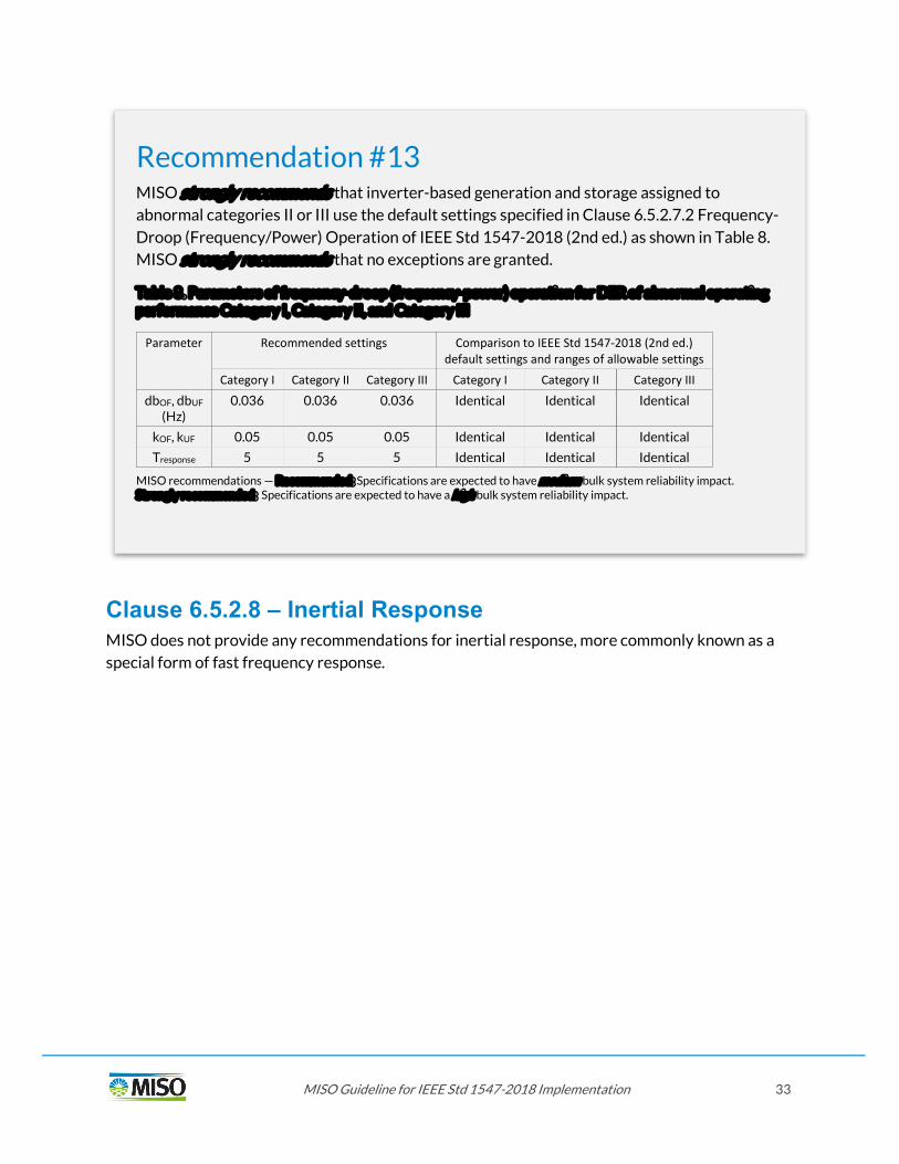
Clause 6.5.2.8 – Inertial Response MISO does not provide any recommendations for inertial response, more commonly known as a special form of fast frequency response.
Recommendation #13 MISO strongly recommends that inverter-based generation and storage assigned to abnormal categories II or III use the default settings specified in Clause 6.5.2.7.2 Frequency-Droop (Frequency/Power) Operation of IEEE Std 1547-2018 (2nd ed.) as shown in Table 8. MISO strongly recommends that no exceptions are granted.
Table 8. Parameters of frequency-droop (frequency-power) operation for DER of abnormal operating performance Category I, Category II, and Category III
Parameter Recommended settings Comparison to IEEE Std 1547-2018 (2nd ed.) default settings and ranges of allowable settings
Category I Category II Category III Category I Category II Category III
dbOF, dbUF (Hz)
0.036 0.036 0.036 Identical Identical Identical
kOF, kUF 0.05 0.05 0.05 Identical Identical Identical
Tresponse 5 5 5 Identical Identical Identical
MISO recommendations — Recommended: Specifications are expected to have medium bulk system reliability impact. Strongly recommended: Specifications are expected to have a high bulk system reliability impact.


35
Clauses 4.10 – Enter Service and Clause and 6.6 – Return to Service After Trip
Clause 4.10.2 – Enter Service / Clause 6.6 – Return to Service After Trip Following a trip, or when entering service, DER is recommended not to energize the Area EPS until the applicable voltage and system frequency are within the ranges specified in Table 9 and the permit service setting is set to “Enabled”.
Recommendation #14 MISO recommends that DER of any type use enter service / return to service voltage and frequency criteria identical to the default settings specified in Clause 4.10.2 (Enter Service Criteria, see Table 9) from IEEE 1547-2018 Std. MISO recommends to be notified of any exceptions at company level.
Table 9. Enter service criteria for DER of Category I, Category II, and Category III
Enter service criteria for DER of Category I, Category II, and Category III (Table 4 in IEEE Std 1547™-2018)
Enter service criteria Default settings
Comparison to IEEE Std 1547-2018 (2nd ed.) allowable setting
Within ranges of allowable settings?
Permit service Enabled Identical Yes
Applicable voltage within range
Minimum value
0.917 p.u. Identical Yes
Maximum value
1.05 p.u. Identical Yes
Frequency within range
Minimum value
59.5 Hz Identical Yes
Maximum value
60.1 Hz Identical Yes
MISO recommendations — Recommended: Specifications are expected to have medium bulk system reliability impact. Strongly recommended: Specifications are expected to have a high bulk system reliability impact.
36
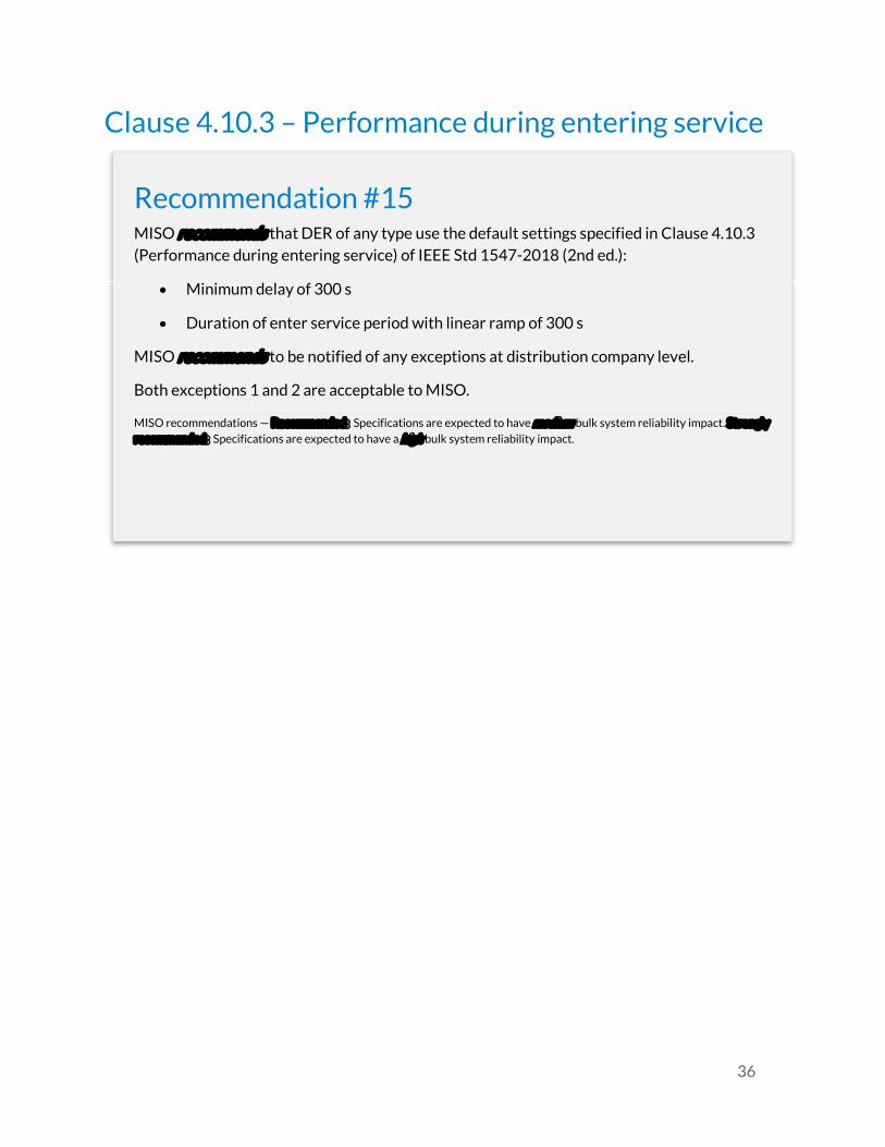
Clause 4.10.3 – Performance during entering service
Recommendation #15 MISO recommends that DER of any type use the default settings specified in Clause 4.10.3 (Performance during entering service) of IEEE Std 1547-2018 (2nd ed.):
Minimum delay of 300 s
Duration of enter service period with linear ramp of 300 s
MISO recommends to be notified of any exceptions at distribution company level.
Both exceptions 1 and 2 are acceptable to MISO.
MISO recommendations — Recommended: Specifications are expected to have medium bulk system reliability impact. Strongly recommended: Specifications are expected to have a high bulk system reliability impact.
37
References
[1] IEEE, "IEEE Standard for Interconnection and Interoperability of Distributed Energy Resources with Associated Electric Power Systems Interfaces. IEEE Std. 1547-2018," April 2018. [Online]. Available: https://site.ieee.org/sagroups-scc21/standards/1547rev/.
[2] C. Sweet, "A new Template for the Integrated Grid. How a Revised National Standard for Distributed Energy Resources Could Change the Power System," EPRI Journal, March/April 2019. [Online]. Available: http://eprijournal.com/wp-content/uploads/2019/04/2019.03-F2_TemplateIntegratedGrid.pdf.
[3] EPRI, "Training Module. Overview on IEEE Std 1547-2018. 3002014545," October 2018. [Online]. Available: https://www.epri.com/#/pages/product/000000003002014545/.
[4] EPRI, "Training Module. DER Ride-through Performance Categories and Trip Settings. 3002014546," November 2018. [Online]. Available: https://www.epri.com/#/pages/product/000000003002014546/.
[5] EPRI, "Training Module. T+D Coordination for DER Ride-Through and Trip Requirements. 3002014547," [Online]. Available: https://www.epri.com/#/pages/product/000000003002014547/.
[6] MISO, "IEEE 1547 - Distribution Interconnection Coordination," [Online]. Available: https://www.misoenergy.org/planning/generator-interconnection/ieee-1547/.
[7] PJM Interconnection, "DER Ride Through Task Force," [Online]. Available: https://www.pjm.com/committees-and-groups/task-forces/derrttf.aspx.
[8] PJM, "PJM Interconnection (Q4 2019): PJM Guideline for Ride Through Performance of Distribution-Connected Generators," [Online]. Available: https://www.pjm.com/-/media/committees-groups/task-forces/derrttf/20190913/20190913-pjm-guideline-for-ride-through-performance-rev1.ashx.
[9] ISO NE, "Inverter Source Requirement Document of ISO New England (ISO-NE)," [Online]. Available: https://www.iso-ne.com/static-assets/documents/2018/02/a2_implementation_of_revised_ieee_standard_1547_iso_source_document.pdf.
[10] MA TSRG, "Massachusetts Technical Standards Review Group," [Online]. Available: https://sites.google.com/site/massdgic/home/interconnection/technical-standards-review-group.
38
[11] Electric Power Research Institute (EPRI), "Recommended Settings for Voltage and Frequency Ride-Through of Distributed Energy Resources. Minimum and Advanced Requirements and Settings for the Performance of Distributed Energy Resources During and After System Disturbances to Support Bulk Power Syst," 3002006203, 2015. [Online]. Available: https://www.epri.com/#/pages/product/000000003002006203/.
[12] EPRI, "Transmission and Distribution Operations and Planning Coordination. TSO/DSO and Tx/Dx Planning Interaction, Processes, and Data Exchange," 3002016712, [Online]. Available: https://www.epri.com/#/pages/product/000000003002016712/ .
[13] EPRI, "DER Modeling Guidelines for Transmission Planning Studies: 2018 Summary. Technical Update. 3002013503.," [Online]. Available: https://www.epri.com/#/pages/product/000000003002013503/.
[14] A. Levitt, "Implementing Ride Through from Distributed Energy Resources.," Presentation at PJM DER Ride Through Task Force. PJM Interconnection., 2019. [Online]. Available: Available online at https://pjm.com/-/media/committees-groups/task-forces/derrttf/20190730-workshop/20197030-item-18-implementing-ride-through-from-distributed-energy-resources.ashx.
[15] EPRI, "Navigating DER Interconnection Standards and Practices. Supplemental Project Notification. 3002012048," October 2017. [Online]. Available: https://www.epri.com/#/pages/product/000000003002012048/.
[16] Electric Power Research Institute (EPRI) , "Post-Technical Conference Comments on participation of distributed energy resource (DER) aggregations in Regional Transmission Organization and Independent System Operator Markets," Comments on Panel 4 and Panel 5 Docket No. AD18-10-000, [Online]. Available: https://elibrary.ferc.gov/idmws/search/intermediate.asp?link_file=yes&doclist=14683720 .
[17] EPRI, "The New Aggregated Distributed Energy Resources (der_a) Model for Transmission Planning Studies.," Update. White Paper. 3002015320., 2019 . [Online]. Available: Available online at https://www.epri.com/#/pages/product/000000003002015320/.
[18] North American Electric Reliability Corporation (NERC), "Performance of Distributed Energy Resources During and After System Disturbance. Voltage and Frequency Ride-Through Requirements.," A report by the Integration of Variable Generation Task Force (Task 1-7), 2013. [Online]. Available: http://www.nerc.com/pa/RAPA/ra/Reliability%20Assessments%20DL/IVGTF17_PC_FinalDraft_December_clean.pdf .

39
APPENDIX Table A. MISO Recommended Settings for DER of Category I
SPECIFICATION INFORMATION
Utility Midcontinent Independent System Operator (MISO)
URP Name MISO_Synchronous_DER
Version Nov-19
SRD Name IEEE Std 1547-2018
Normal Performance Category Category A (outside the scope of this guideline)
Abnormal Performance Category Category I
Contact
Name
Phone Number, Work
Phone Number, Cell
Checksum
4.10
ENTER SERVICE CRITERIA Parameter Name 1547.1 UNITS Utility-
Required Setting
Default, Valid, Invalid
Permit Service PS Mode_AS Mode Enabled Default
Voltage Minimum value ES F low_AS V p.u. 0.917 Default Maximum value ES F high_AS V p.u. 1.05 Default
Frequency Minimum value ES F low_AS Hz 59.5 Default Maximum value ES F high_AS Hz 60.1 Default
Minimum Intentional delay ES Delay_AS s 300 Default
Soft-Start Ramp duration ES Ramp Time_AS s 300 Default
6.4.1
MANDATORY VOLTAGE TRIPPING CHARACTERISTICS Parameter Name 1547.1 UNITS/ MODE
Utility-Required Setting
Default, Valid, Invalid
OV3 OV3, Trip Voltage Magnitude OV3 Trip V_AS V p.u. N/A Default
OV3, Clearing Time Duration OV3 Trip t_AS s N/A Default
OV2 OV2, Trip Voltage Magnitude OV2 Trip V_AS V p.u. 1.20 Default OV2, Clearing Time Duration OV2 Trip t_AS s 0.16 Default
OV1 OV1, Trip Voltage Magnitude OV1 Trip V_AS V p.u. 1.10 Default OV1, Clearing Time Duration OV1 Trip t_AS s 2.0 Default
UV1 UV1, Trip Voltage Magnitude UV1 Trip V_AS V p.u. 0.70 Default
UV1, Clearing Time Duration UV1 Trip t_AS s 5.0 Valid
UV2 UV2, Trip Voltage Magnitude UV2 Trip V_AS V p.u. 0.45 Default UV2, Clearing Time Duration UV2 Trip t_AS s 0.32 Valid
UV3 UV3, Trip Voltage Magnitude UV3 Trip V_AS V p.u. N/A Default
40
UV3, Clearing Time Duration UV3 Trip t_AS s N/A Default
6.5.1
MANDATORY FREQUENCY TRIPPING CHARACTERISTICS
Parameter Name 1547.1 UNITS/ MODE
Utility-Required Setting
Default, Valid, Invalid
OF2 Trip Frequency Magnitude OF2 Trip f_AS Hz 62.0 Default
Clearing Time Duration OF2 Trip t_AS s 0.16 Default
OF1 Trip Frequency Magnitude OF1 Trip f_AS Hz 61.2 Default
Clearing Time Duration OF1 Trip t_AS s 300 Default
UF1 Trip Frequency Magnitude UF1 Trip f_AS Hz 58.5 Default
Clearing Time Duration UF1 Trip t_AS s 300 Default
UF2 Trip Frequency Magnitude UF2 Trip f_AS Hz 56.5 Default
Clearing Time Duration UF2 Trip t_AS s 0.16 Default
6.5.2.7.2
FREQUENCY-DROOP (Frequency-Watt, P(f)) Parameter Name 1547.1 UNITS
Utility-Required Setting
Default, Valid, Invalid
Frequency-Droop Activation P(f) Mode_AS Mode Enabled Default
Deadband dbOF Pf dbOF_AS Hz 0.036 Default dbUF Pf dbUF_AS Hz 0.036 Default
Coefficient kOF Pf kOF_AS unitless 0.05 Default kUF Pf kUF_AS unitless 0.05 Default
Open Loop Response Time Pf OLRT_AS s 5 Default

41
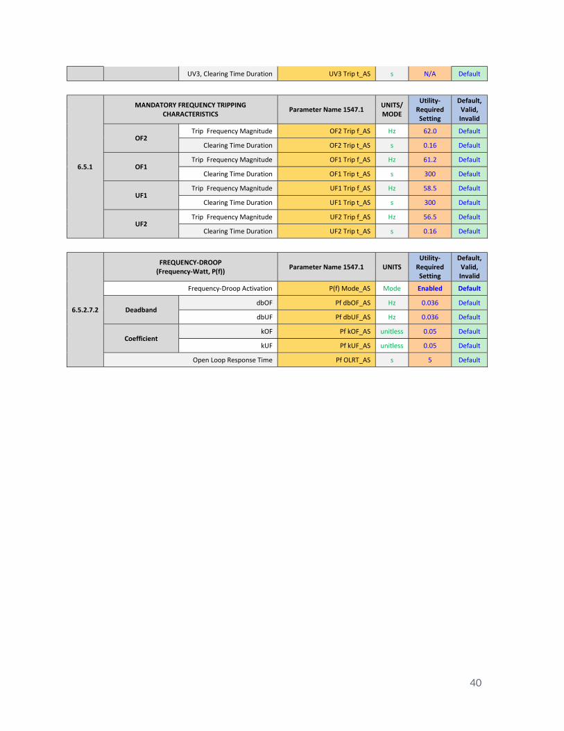
Table B. MISO Recommended Settings for DER of Category III when amended or Cat II
SPECIFICATION INFORMATION
Utility Midcontinent Independent System Operator (MISO)
URP Name MISO_Inverter_DER
Version Nov-19
SRD Name IEEE Std 1547-2018
Normal Performance Category Category B (outside the scope of this guideline)
Abnormal Performance Category Category III
Contact
Name
Phone Number, Work
Phone Number, Cell
Checksum
4.10
ENTER SERVICE CRITERIA Parameter Name 1547.1 UNITS Utility-
Required Setting
Default, Valid, Invalid
Permit Service PS Mode_AS Mode Enabled Default
Voltage Minimum value ES F low_AS V p.u. 0.917 Default Maximum value ES F high_AS V p.u. 1.05 Default
Frequency Minimum value ES F low_AS Hz 59.5 Default Maximum value ES F high_AS Hz 60.1 Default
Minimum Intentional delay ES Delay_AS s 300 Default
Soft-Start Ramp duration ES Ramp Time_AS s 300 Default
6.4.1
MANDATORY VOLTAGE TRIPPING CHARACTERISTICS Parameter Name 1547.1 UNITS Utility-
Required Setting
Default, Valid, Invalid
OV3 OV3, Trip Voltage Magnitude OV3 Trip V_AS V p.u. N/A Default
OV3, Clearing Time Duration OV3 Trip t_AS s N/A Default
OV2 OV2, Trip Voltage Magnitude OV2 Trip V_AS V p.u. 1.20 Default OV2, Clearing Time Duration OV2 Trip t_AS s 0.16 Default
OV1 OV1, Trip Voltage Magnitude OV1 Trip V_AS V p.u. 1.10 Default OV1, Clearing Time Duration OV1 Trip t_AS s 2.0 Valid
UV1 UV1, Trip Voltage Magnitude UV1 Trip V_AS V p.u. 0.70 Valid
UV1, Clearing Time Duration UV1 Trip t_AS s 5.0 Valid
UV2 UV2, Trip Voltage Magnitude UV2 Trip V_AS V p.u. 0.45 Valid UV2, Clearing Time Duration UV2 Trip t_AS s 0.32 Valid
UV3 UV3, Trip Voltage Magnitude UV3 Trip V_AS V p.u. N/A Default UV3, Clearing Time Duration UV3 Trip t_AS s N/A Default

42
6.5.1
MANDATORY FREQUENCY TRIPPING CHARACTERISTICS Parameter Name 1547.1 UNITS
Utility-Required Setting
Default, Valid, Invalid
OF2 Trip Frequency Magnitude OF2 Trip f_AS Hz 62.0 Default
Clearing Time Duration OF2 Trip t_AS s 0.16 Default
OF1 Trip Frequency Magnitude OF1 Trip f_AS Hz 61.2 Default
Clearing Time Duration OF1 Trip t_AS s 300 Default
UF1 Trip Frequency Magnitude UF1 Trip f_AS Hz 58.5 Default
Clearing Time Duration UF1 Trip t_AS s 300 Default
UF2 Trip Frequency Magnitude UF2 Trip f_AS Hz 56.5 Default
Clearing Time Duration UF2 Trip t_AS s 0.16 Default
6.5.2.7.2
FREQUENCY-DROOP (Frequency-Watt, P(f))
Parameter Name 1547.1 UNITS Utility-
Required Setting
Default, Valid, Invalid
Frequency-Droop Activation P(f) Mode_AS Mode Enabled Default
Deadband dbOF Pf dbOF_AS Hz 0.036 Default
dbUF Pf dbUF_AS Hz 0.036 Default
Coefficient kOF Pf kOF_AS unitless 0.05 Default kUF Pf kUF_AS unitless 0.05 Default
Open Loop Response Time Pf OLRT_AS s 5 Default