MIPI M-PHY Transmitter and Receiver Test Solutions - M...
12
MIPI ® M-PHY Transmitter and Receiver Test Solutions M-PHYTX/M-PHYRX Automated, M-PHY Essentials / Protocol Decode Features & Benefits M-PHY Receiver Testing Simple setup using a Tektronix oscilloscope and arbitrary waveform generator for a complete Receiver as well as Transmitter testing of M-PHY traffic. No other instrument is needed Automated testing for Gear1A and Gear1B data rates reduces the complexity of executing Receiver tests and enables you to test devices faster Integrated BER leverages bit error rate or error count testing using oscilloscope-integrated ERRDT software in the background for all Gears (A and B). No external/extra hardware is required to perform BER testing Modify the test setup according to the DUT configurations such as the High-speed Gear, Automatic or Manual Error-Detection Mechanism, Test Time or Loopback Duration, etc. Detailed test reports provide a Pass/Fail summary table, with additional information such as Test Setup Details, Signal Types, Bit Error, Execution Time, etc. for each measurement Test setup with arbitrary waveform generator Supports flexible signal impairments using SerialXpress optionally for characterization of Gear1, Gear2, and Gear3 (all A and B) data rates Supports jitter insertion and Pulse Width Modulation (PWM) generation according to the base specification v1.0 for all PWM Gears Supports testing the DUT in both Loopback (either Automated or Manual steps) and Non-loopback (Manual steps) mode M-PHY Transmitter Testing Automated testing reduces the complexity of executing Transmitter tests and enables you to test devices faster Highly optimized setup performs Power Spectral Density (PSD) tests using oscilloscope-integrated algorithms uniquely, and does not require an external spectral analyzer or extra hardware to perform PSD measurements Automates the most complete 95% test coverage of High Speed for all Gears including Gear3, and 75% test coverage of PWM measurements for all PWM Gears M-PHYTX Automated User-defined mode allows modifying every parameter of different HS and PWM tests, for comprehensive debug analysis and characterization Seamless debug allows pause on each test in automation, and switch to DPOJET analysis tool for detailed debug Configuration for regression allows selecting different Gears and sub-Gears of HS and PWM signals, large/small amplitudes, impedance termination/un-termination User-defined mode allows configurations beyond compliance settings Opt. M-PHY Essentials enable full customization and comprehensive characterization using setup libraries Single printable report for approximately 1000 tests across different combinations, provides Pass/Fail summary table, along with margin details, optional waveform captures, and eye diagrams M-PHY UniPro and LLI Decode Leverages the Oscilloscope Serial Trigger (ST6G) Triggers on the UniPro and LLI specific events for all Gears 4-lane automated decoding Automatically identifies all Gears and signalling schemes, and decodes Automatically verifies CRC errors in the protocol packets Acquires up to 4 lanes of data traffic simultaneously, and correlates the lane-to-lane events Protocol to physical-layer data correlation Automatically links protocol decode data to the waveforms on oscilloscope Enables faster system-level protocol debugging
Transcript of MIPI M-PHY Transmitter and Receiver Test Solutions - M...

MIPI® M-PHY Transmitter and Receiver Test SolutionsM-PHYTX/M-PHYRX Automated, M-PHY Essentials / Protocol Decode
Features & BenefitsM-PHY Receiver Testing
Simple setup using a Tektronix oscilloscope and arbitrary waveformgenerator for a complete Receiver as well as Transmitter testing ofM-PHY traffic. No other instrument is neededAutomated testing for Gear1A and Gear1B data rates reduces thecomplexity of executing Receiver tests and enables you to test devicesfasterIntegrated BER leverages bit error rate or error count testing usingoscilloscope-integrated ERRDT software in the background for all Gears(A and B). No external/extra hardware is required to perform BER testingModify the test setup according to the DUT configurations such as theHigh-speed Gear, Automatic or Manual Error-Detection Mechanism, TestTime or Loopback Duration, etc.Detailed test reports provide a Pass/Fail summary table, with additionalinformation such as Test Setup Details, Signal Types, Bit Error,Execution Time, etc. for each measurementTest setup with arbitrary waveform generator
Supports flexible signal impairments using SerialXpress optionally forcharacterization of Gear1, Gear2, and Gear3 (all A and B) data ratesSupports jitter insertion and Pulse Width Modulation (PWM)generation according to the base specification v1.0 for all PWM GearsSupports testing the DUT in both Loopback (either Automated orManual steps) and Non-loopback (Manual steps) mode
M-PHY Transmitter Testing
Automated testing reduces the complexity of executing Transmitter testsand enables you to test devices faster
Highly optimized setup performs Power Spectral Density (PSD) testsusing oscilloscope-integrated algorithms uniquely, and does not requirean external spectral analyzer or extra hardware to perform PSDmeasurements
Automates the most complete 95% test coverage of High Speed for allGears including Gear3, and 75% test coverage of PWM measurementsfor all PWM Gears
M-PHYTX Automated User-defined mode allows modifying everyparameter of different HS and PWM tests, for comprehensive debuganalysis and characterization
Seamless debug allows pause on each test in automation, and switch toDPOJET analysis tool for detailed debug
Configuration for regression allows selecting different Gears andsub-Gears of HS and PWM signals, large/small amplitudes, impedancetermination/un-termination
User-defined mode allows configurations beyond compliance settings
Opt. M-PHY Essentials enable full customization and comprehensivecharacterization using setup libraries
Single printable report for approximately 1000 tests across differentcombinations, provides Pass/Fail summary table, along with margindetails, optional waveform captures, and eye diagrams
M-PHY UniPro and LLI Decode
Leverages the Oscilloscope Serial Trigger (ST6G)Triggers on the UniPro and LLI specific events for all Gears
4-lane automated decodingAutomatically identifies all Gears and signalling schemes, anddecodesAutomatically verifies CRC errors in the protocol packetsAcquires up to 4 lanes of data traffic simultaneously, and correlatesthe lane-to-lane events
Protocol to physical-layer data correlationAutomatically links protocol decode data to the waveforms onoscilloscopeEnables faster system-level protocol debugging

Datasheet
M-PHY 8b-10b DecodeAll M-PHY Gears
Decodes M-PHY data traffic up to 6.25 Gb/s data rate, from symbolsor 10-bit into 8-bit data
Trigger and searchSupports trigger and search on any control character,character/symbol, error (character error and disparity error), or pattern
Custom decodeAdditionally, Option SR-CUST Custom Serial Analysis Kit can be usedfor any custom protocols decoding up to 6.25 Gb/s data rate
M-PHY DigRFv4 DecodeAutomated decoding
Automatically recognizes data speeds, disassembles, and displaysthe decoded data in different readable-data formats
4-lane decodingAcquires up to 4 lanes of data traffic at a time
Online, offline, and remote analysisSupports LAN interface, and leverages TekVISA to connect toTektronix oscilloscopes
Filter, Search, and Option tabsSearches and filters the decoded messages based on user criteria
ApplicationsM-PHY Transmitter and Receiver testing for:
M-PHY host and device silicon characterization, debug, and validationM-PHY conformance testing3rd-party components verificationProtocol verificationSystem integration and validationManufacturing test
Single-button automated M-PHY Transmitter testing.
M-PHY Transmitter/Receiver Testing withM-PHYTX/M-PHYRXSingle-button Automated M-PHY Transmitter/ReceiverTestingThe Tektronix M-PHYTX/M-PHYRX Automated Test software runs onTektronix real-time oscilloscopes that are based on Windows XP*1 orWindows 7*1 computer operating systems. M-PHYTX/M-PHYRX providesan automated, simple, and efficient way to test M-PHY Transmitter/Receiverinterfaces and devices consistent to the requirements of the M-PHY BaseSpecification v1.0 and Conformance Test Specification.Once the test bench is set up and the DUT is properly connected, simplypress the Run button to perform the selected test suite.*1 See host system requirements in the Ordering Information section.
Automated Transmitter/Receiver Testing – Save Timeand ResourcesThere is no longer a need to be an expert on testing procedures.Remembering the exact steps to take each measurement is timeconsuming and often requires going back to the M-PHY specifications.M-PHYTX/M-PHYRX takes the guesswork out of conducting M-PHYTransmitter/Receiver testing. Even if you remember how to use the testequipment, it is common for even the most experienced operators to forgetsteps in the procedure or to set up the correct parameters, such as applyingthe correct signal impairments for a given test. M-PHYTX/M-PHYRX allowsengineers to simply select the desired tests to run, and then work on othertasks while the tests are being executed.
2 www.tektronix.com

MIPI® M-PHY Transmitter and Receiver Test Solutions — M-PHYTX/M-PHYRX Automated, M-PHY Essentials / ProtocolDecode
M-PHYRX simple setup, test execution, and reporting, through Non-interleave channels ofan AWG7000.
Simple Setup, Test Execution, and ReportingTest setup and test execution is very simple with the M-PHYTX/M-PHYRXAutomated software. The test setup connections are very minimal, as itinvolves only one piece of equipment for M-PHYTX and only two piecesof equipment for M-PHYRX. M-PHYRX controls the Arbitrary WaveformGenerator (AWG) and Oscilloscope Error Detector. The TekExpresssoftware provides a Graphical User Interface (GUI) and an intuitive workflowthrough setup and testing.
Setting Up the BenchWhen setting up a test, nothing can be simpler than hooking up the testsystem by looking at a schematic. View the schematic of the selected testwith a push of a button.
Instrument Bench DiscoveryM-PHYRX software automatically (or on demand) scans and detectssupported instruments connected in your test bench (both Visa supportedand non-Visa supported instruments), whether they are connected throughLAN, or GPIB. A quick check of the Instrument Bench menu confirms allinstruments are networked correctly.
Comprehensive Transmitter/Receiver Test CoveragePerform regression of almost all the High Speed mode Transmitter andSelective High Speed mode Receiver tests such as Receiver JitterTolerance, Receiver Eye Opening, Common Mode or Differential InputVoltage Tolerance, etc. In addition, perform regression of most of the PWMTransmitter tests uniquely across all PWM Gears (G0 to G7).
Counting bit errors using Oscilloscope Error Detector, in DUT Receiver loopback.
M-PHYRX Loopback Initiation and RetentionBefore the Receiver test can start, the device under test must be put in theproper test mode, called Loopback, where the DUT loops the incomingsignal at Rx directly to the Tx port. Once the Loopback is set on theDUT, then the Arbitrary Waveform Generator sends a Continuous modesignal with recommended patterns for all measurements. The M-PHYRXAutomated software will allow the user to configure the Loopback settingsinitially, and retain them for subsequent test executions by sending thesignal continuously during the transition from one test to another.
M-PHYRX Error Detection – Both Scope-based andManualM-PHYRX software supports two methods of error detection. The firstmethod uses oscilloscope-based error detection and counting, leveragingthe oscilloscope-integrated ERRDT software in the background. Thesecond method uses a dialog box to read a manual entry of error counts.
M-PHYRX Ease of Testing with Pre-calibrated PatternsThe AWG (Arbitrary Waveform Generator) patterns are generated andfactory calibrated to ensure the impairments are within the specificationwith given golden accessories. This simplifies the number of patterns aswell as limits the time-consuming calibration routines. Both the AWG andOscilloscope Error Detector work together concurrently in Loopback mode,and pre-calibrated signals enable you to perform each measurement withinthree minutes of time.
www.tektronix.com 3

Datasheet
Pass/Fail ReportThe M-PHYTX Report tab provides a single printable report of approx.1000 test results along with a Pass/Fail summary table, margins, andoptionally waveform screen captures, eye diagrams, histograms, bathtubcharts, etc. The M-PHYRX Report tab provides a view of test results alongwith Pass/Fail status and bit error counts. Upon completion of the test, acomprehensive report will be generated in .MHT format. The results of thetest will also be stored in an Excel .XLS file that can be used for further dataanalysis. Included in the test report are the configuration settings for the testequipment, test execution times, and comments for each test.
Powered by NI TestStand™The TekExpress automated compliance software uses NI (NationalInstruments) TestStand to manage and execute its test sequences. AWindows user interface is provided in the TekExpress software for simpleand complete operation of compliance measurements. However, ifyour validation and debug needs go beyond the features offered by theTekExpress software, a full version of NI TestStand can be used to develophigher-level automation sequences to control the TekExpress software.NI TestStand is the de facto industry-standard test managementenvironment for automating test and validation systems. NI TestStand isused to develop, manage, and execute test sequences, and to integrate testmodules written in any test programming language through an open andflexible architecture. Customers who own NI TestStand and purchase theTekExpress software will be able to write scripts using NI TestStand that callthe TekExpress software with a detailed list of commands. This commandset allows the NI TestStand user to recall and save TekExpress softwaresetups, control individual test parameters, control test selections, changeUI selections, change global parameters, start execution, query currentexecution status, and receive measurement results.
M-PHY Transmitter testing with M-PHYTX Automated or M-PHY Essentials usingsingle-ended/differential probes.
For device validation, it’s often desirable to make multiple runs of a singledevice using different operating conditions such as temperature andpower supply voltages. This is sometimes referred to as ‘four-cornerstesting’, (testing to low-high temperature and low-high supply voltages).For four-corners testing, NI TestStand supports drivers for a wide rangeof temperature chambers and power supplies. NI TestStand can beused to control the temperature chamber and then call the TekExpresssoftware for a compliance test using the limited command set. Foradjusting power supply voltages, the power supply control sequencefile within the TekExpress software can be modified using a standardNI TestStand sequence file. So if your company already uses NI TestStandfor automation, your test engineers can incorporate commands to run theTekExpress compliance software directly into their test sequences.
M-PHY Transmitter Testing with M-PHYEssentialsDPOJET software with Option M-PHY provides the essential set ofM-PHY Transmitter measurements with greater flexibility in the test setup.Like D-PHY Essentials on DPOJET, M-PHY Essentials also enablesCharacterization, Debug, Analysis, and Conformance testing of M-PHYdesigns.
100%M-PHY High-speed Transmitter Test CoverageM-PHY Essentials supports complete measurements to be performedin High-speed mode. It includes unique measurements such as PowerSpectral Density on the real-time oscilloscope itself. It’s a patent-pendingmethodology supported by Tektronix. Alternative solutions in the marketrequire additional hardware to perform this test. Moreover, M-PHYEssentials slew rate measurement can be extended to slew rate resolutionmeasurement.
4 www.tektronix.com

MIPI® M-PHY Transmitter and Receiver Test Solutions — M-PHYTX/M-PHYRX Automated, M-PHY Essentials / ProtocolDecode
Transmitter eye diagram measurement using M-PHYTX Automated or M-PHY Essentials.
Transmitter Power Spectral Density measurement using M-PHYTX Automated or M-PHYEssentials.
Transmitter Eye DiagramMeasurementEye diagram measurement performs the Transmitter Eye Opening (TEYE_TX)requirement at the minimum Differential AC Output Voltage Amplitude(VDIF_AC_xA_xT_TX), for all combinations of supported Amplitudes, Terminations,Gears, and Lanes.
Transmitter Power Spectral Density MeasurementPower Spectral Density (PSD) refers to the amount of power per unit(density) of frequency (spectral) as a function of the frequency. The PSDdescribes how the power (or variance) of a time series is distributed withfrequency. The Power Spectral Density measurement is performed onthe Tektronix oscilloscope itself using the patent-pending algorithms tocompute the PSD waveform display, compare it against upper and lowermask limits, and then provide the result as Pass or Fail. Performing this
PGY-UPRO and PGY-LLI decode.
measurement on Tektronix oscilloscopes does not require any additionalexternal instruments, such as spectral analyzers.
Oscilloscope-based Decode for M-PHYUniPro and LLIM-PHY design and test engineers need to monitor and debug UniPro/LLIprotocol interfaces to ensure reliable operation of the system. Manuallyinterpreting the protocol layer information using oscilloscope data istime consuming and prone to human error in a versatile UniPro and LLIprotocol standard. The Prodigy PGY-UPRO/PGY-LLI Protocol Decodesoftware offers extensive protocol decoding for M-PHY UniPro/LLI protocolspecifications respectively. With this software, the M-PHY design and testengineers can now automatically make accurate and reliable decodes ofmulti-lane data, acquired by a Tektronix DPO/DSA/MSO70000 oscilloscope,and significantly reduce the development and test cycle.The PGY-UPRO/PGY-LLI software automatically identifies all gears andsignalling schemes such as NRZ and PWM, and decodes the protocolframes of multi-lane traffic. Built up on oscilloscope serial trigger features,the software computes CRC and verifies for CRC errors in a UniPro/LLIprotocol packet. The software also links the decoded data to the electricalsignal in the oscilloscope display, enabling better correlation from protocol-to physical-layer data. Furthermore, the software generates comprehensiveand customizable reports, along with protocol data exportable in .TXT and.CSV formats. The software conforms to the M-PHY specification v1.0, theUniPro specification v1.4, and the LLI specification v0.8.
www.tektronix.com 5

Datasheet
Oscilloscope-based decode for M-PHY 8b-10b.
Oscilloscope-based Decode for M-PHY 8b-10bThe SR-810B Serial Analysis application option enables Decode,Search, and Trigger on 8b/10b bus events for fast verification. AllTektronix MSO/DPO/DSA70000 Series oscilloscopes are equippedwith a dedicated trigger chip for triggering on 8b/10b data patterns inhigh-speed serial signals up to 6.25 Gb/s. Installed as part of TekScopefirmware, this software ensures finding even rare events. Furthermore, theDPO/DSA/MSO70000 Series oscilloscopes with PTD software supportseveral 8b10b data values for triggering.A very unique feature of the SR-810B option and perhaps the most powerfuldebugging tool is the capability to trigger on 8b/10b code errors. No serialtrigger would be able to trigger on all possible character errors, disparityerrors, or losses of byte synchronization, but the Tektronix 8b/10b serialtrigger allows triggering on common errors such as disparity or charactererrors.
Oscilloscope-based decode for M-PHY DigRFv4.
Oscilloscope-based Decode for M-PHYDigRFv4The Moving Pixel MPHYVIEW Protocol Decode software automaticallyrecognizes M-PHY data speeds, disassembles, decodes the DigRFv4 datastreams, and displays the decoded data in different readable-data formats.The software can be configured to acquire up to 4 lanes of data traffic at atime.The MPHYVIEW software can be connected to a remote oscilloscope, andexecuted remotely from any Windows system, using TekVISA. The Filterand Search tabs enable searching and possibly highlighting records thatsatisfy given criteria. The MPHYVIEW also supports bit-sync, align, 10b-8bdecode form packets, and disassemble.
Required Equipment for MIPI® (M-PHY andD-PHY) Transmitter and Receiver TestingFor a complete list of required equipment please visithttp://www.tek.com/MIPI.
6 www.tektronix.com
MIPI® M-PHY Transmitter and Receiver Test Solutions — M-PHYTX/M-PHYRX Automated, M-PHY Essentials / ProtocolDecode
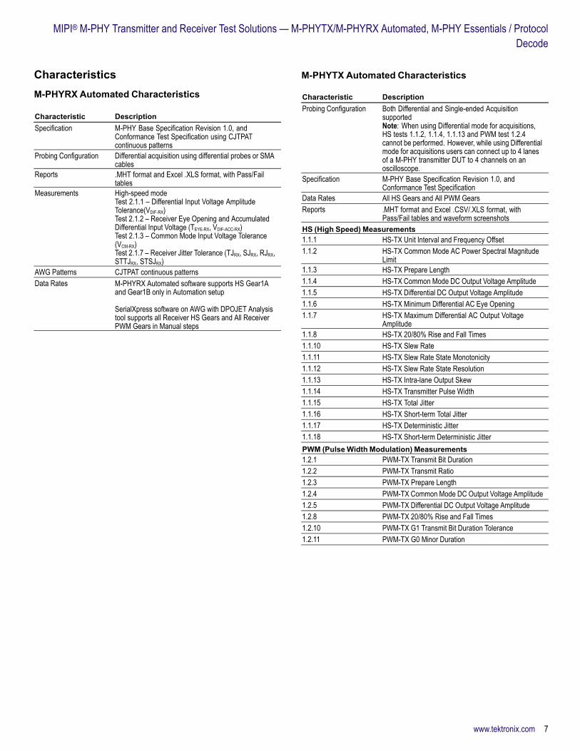
CharacteristicsM-PHYRX Automated Characteristics
Characteristic DescriptionSpecification M-PHY Base Specification Revision 1.0, and
Conformance Test Specification using CJTPATcontinuous patterns
Probing Configuration Differential acquisition using differential probes or SMAcables
Reports .MHT format and Excel .XLS format, with Pass/Failtables
Measurements High-speed modeTest 2.1.1 – Differential Input Voltage AmplitudeTolerance(VDIF-RX)Test 2.1.2 – Receiver Eye Opening and AccumulatedDifferential Input Voltage (TEYE-RX, VDIF-ACC-RX)Test 2.1.3 – Common Mode Input Voltage Tolerance(VCM-RX)Test 2.1.7 – Receiver Jitter Tolerance (TJRX, SJRX, RJRX,STTJRX, STSJRX)
AWG Patterns CJTPAT continuous patternsData Rates M-PHYRX Automated software supports HS Gear1A
and Gear1B only in Automation setup
SerialXpress software on AWG with DPOJET Analysistool supports all Receiver HS Gears and All ReceiverPWM Gears in Manual steps
M-PHYTX Automated Characteristics
Characteristic DescriptionProbing Configuration Both Differential and Single-ended Acquisition
supportedNote: When using Differential mode for acquisitions,HS tests 1.1.2, 1.1.4, 1.1.13 and PWM test 1.2.4cannot be performed. However, while using Differentialmode for acquisitions users can connect up to 4 lanesof a M-PHY transmitter DUT to 4 channels on anoscilloscope.
Specification M-PHY Base Specification Revision 1.0, andConformance Test Specification
Data Rates All HS Gears and All PWM GearsReports .MHT format and Excel .CSV/.XLS format, with
Pass/Fail tables and waveform screenshotsHS (High Speed) Measurements1.1.1 HS-TX Unit Interval and Frequency Offset1.1.2 HS-TX Common Mode AC Power Spectral Magnitude
Limit1.1.3 HS-TX Prepare Length1.1.4 HS-TX Common Mode DC Output Voltage Amplitude1.1.5 HS-TX Differential DC Output Voltage Amplitude1.1.6 HS-TX Minimum Differential AC Eye Opening1.1.7 HS-TX Maximum Differential AC Output Voltage
Amplitude1.1.8 HS-TX 20/80% Rise and Fall Times1.1.10 HS-TX Slew Rate1.1.11 HS-TX Slew Rate State Monotonicity1.1.12 HS-TX Slew Rate State Resolution1.1.13 HS-TX Intra-lane Output Skew1.1.14 HS-TX Transmitter Pulse Width1.1.15 HS-TX Total Jitter1.1.16 HS-TX Short-term Total Jitter1.1.17 HS-TX Deterministic Jitter1.1.18 HS-TX Short-term Deterministic JitterPWM (Pulse Width Modulation) Measurements1.2.1 PWM-TX Transmit Bit Duration1.2.2 PWM-TX Transmit Ratio1.2.3 PWM-TX Prepare Length1.2.4 PWM-TX Common Mode DC Output Voltage Amplitude1.2.5 PWM-TX Differential DC Output Voltage Amplitude1.2.8 PWM-TX 20/80% Rise and Fall Times1.2.10 PWM-TX G1 Transmit Bit Duration Tolerance1.2.11 PWM-TX G0 Minor Duration
www.tektronix.com 7

Datasheet
M-PHY Essentials Characteristics
Characteristic DescriptionM-PHY BaseSpecification
Revision 1.0
M-PHY ConformanceTest Specification
Revision 0.65
Probing Configuration Single-ended acquisition using single-ended probes, ordifferential probes in a single-ended fashion
Reports MHT format, with Pass/Fail tables and waveformscreenshots
The following tables provide the details of M-PHY Essentials transmitter testcoverage for the base specification.
M-PHY Essentials – Tx Measurements (Base Specification)Test Name andGroup
Test Symbol HS-LargeSwing HS-SmallSwing
VDIF_PK_L_NT_TX Yes YesVDIF_PK_L_RT_TX Yes YesVDIF_PK_S_NT_TX Yes Yes
Differential Peak toPeak Voltage
VDIF_PK_S_RT_TX Yes YesVCM_S_TX Yes YesCommon Mode
Voltage VCM_L_TX Yes YesSlew Rate inFastest Slew RateState
SRDIF_TX Yes Yes
Transmitter PulseWidth
TPULSE_TX Yes Yes
Eye Opening TEYE_TX Yes YesDeterministic Jitter DJTX Yes YesTotal Jitter TJTX Yes YesTotal Jitter for ShortLane
TJTX Yes Yes
Short Term Jitter STJTX Yes YesResolution of SlewRate States
ΔSRDIF_TX Yes Yes
Power SpectralDensity/Magnitude
PSD Yes Yes
Ordering Information
M-PHYRX AutomatedModel DescriptionDPO/DSA/MSO70000CDPO/DSA70000D
DPO (Digital Phosphor Oscilloscope), DSA (DigitalSerial Analyzer), or MSO (Mixed Signal Oscilloscope)Oscilloscopes –
6 GHz and above is recommended for HS-Gear18 GHz and above is recommended for up to HS-Gear220 GHz and above is recommended for up to HS-Gear3
AWG7000C Arbitrary Waveform Generator –
AWG7082C or AWG7102*3 or AWG7122B/CNon-interleave channels (i.e. with or without Option 06enabled) or above – For HS-Gear1 onlyAWG7122B/C Non-interleave channels (i.e with orwithout Option 06 enabled) – For HS-Gear1 andHS-Gear2 onlyAWG7122B/C with Interleave channels (i.e withOption 06 enabled) – For all HS-Gears in Manual steps
DPO/DSA/MSO70000CDPO/DSA70000DOpt. M-PHYRX*2
DPO-UPOpt. M-PHYRX*2
M-PHY Automated Solution – For HS-Gear1 (A and B)only
Includes: Latest TekExpress product software DVDkit (P/N 020-2913-xx) and upgrade SW key. Onlinedocumentation and printable manual in PDF format aresupplied
DPOFL-M-PHYRX*2 M-PHY Automated Receiver Solution – FloatingLicense
*2 Requires Frame and Bit Error Rate Detector for High-speed Serial Standards (Option ERRDT and ST6G).*3 LAN interface is not supported.
M-PHYTX Automated and M-PHY EssentialsModel DescriptionDPO/DSA/MSO70000C/D DPO (Digital Phosphor Oscilloscope), DSA (Digital
Serial Analyzer), or MSO (Mixed Signal Oscilloscope)Oscilloscopes –
6 GHz and above is recommended for HS-Gear18 GHz and above is recommended for up to HS-Gear220 GHz and above is recommended for up to HS-Gear3
DPO/DSA/MSO70000C/DOpt. M-PHYTX*4
DPO-UPOpt. M-PHYTX*4
M-PHY Automated Transmitter Solution
DPOFL-M-PHYTX*4 M-PHY Automated Transmitter Solution (FloatingLicense version)
DPO/DSA/MSO70000C/DOpt. M-PHY*4
DPO/MSO70000CGSAOpt. M-PHY*4
DPO-UP/DPO7UPOpt. M-PHY*4
MIPI® M-PHY Essentials
DPOFL-M-PHY*4 MIPI® M-PHY Essentials (Floating License version)*4 Requires DPOJET Jitter and Eye Analysis Tools (Opt. DJA).
M-PHY DecodesModel DescriptionPGY-UPRO*5 M-PHY UniPro Protocol Decode (3rd-party software)PGY-LLI*5 M-PHY LLI Protocol Decode (3rd-party software)MPHYVIEW M-PHY DigRFv4 CommView Protocol Decode
(3rd-party software)DPO-UP Opt. SR-810B 8b/10b Serial Analysis*5 Requires Opt. ST6G Serial Protocol Triggering.
8 www.tektronix.com

MIPI® M-PHY Transmitter and Receiver Test Solutions — M-PHYTX/M-PHYRX Automated, M-PHY Essentials / ProtocolDecode
Fixtures for M-PHY Automated andM-PHY EssentialsM-PHY is a chip-to-chip interface. Most M-PHY designs are live withhost-device/Master-Slave receiver-ends connected. For these live setups nofixtures or termination boards are required, as termination is taken care of by thereceiver end. For non-live setups, M-PHY termination boards are expected to beavailable from University of New Hampshire (UNH-IOL) soon.
Recommended Probes for M-PHYTX Automated, M-PHYEssentials, and M-PHY Decodes- 2x P7240 (HS-Gear1), or- 2x P73xx/P73xxSMA (up to HS-Gear2), or- 2x P75xx with P75LRST tip (up to HS-Gear3)
- 2x P73xx/P73xxSMA for PWM All Gears
PGY-UPRO and PGY-LLI require differential probing. For the DPO70000 Series,P7500 and P7300 Series probes are well suited.
Note: In Differential mode acquisition of M-PHYTX Automated software (i.e. whenusing only one differential probe per lane), HS tests 1.1.2, 1.1.4, 1.1.13 andPWM test 1.2.4 cannot be performed. However, while using Differential modefor acquisitions users can connect up to 4 lanes of a M-PHY transmitter DUT to4 channels on an oscilloscope.
Recommended Probes and Accessories for M-PHYRXAutomated- 1x P73xxSMA Differential Probe- 2x Matched pair of SMA Cables- 1x GPIB Cable- 2x Rise Time Filter – 120 ps (part number 5915-121-120PS from Picosecond)with barrel connectors- 2x BiasTee – For HS-Gear3 only, in Manual steps using SerialXpress andInterleave channels on AWG
Optional Accessories for M-PHY Receiver Testing- 2x TCA-SMA Connectors, for AWG custom patterns creation
Optional Software for M-PHY Receiver Testing- NI TestStand Software – For additional automation and test sequencecustomization (www.ni.com)- SerialXpress Software – For custom-patterns/impairments creation of all Gears- Option 01 – Memory expansion to 64 M enabled on AWG- Option 08 – Fast Sequence Switching enabled on AWG- Option 09 – Subsequence and Dynamic Jump enabled on AWG
Prerequisite Host System Software Requirements forM-PHYTX and M-PHYRX- Microsoft XP OS with SP2 or later, or Windows 7- Microsoft Excel 2002 or above- Microsoft Internet Explorer 6.0 SP1 or later- Adobe Reader 6.0 or equivalent software for viewing Portable Document Format(PDF) files
www.tektronix.com 9

Datasheet
10 www.tektronix.com

MIPI® M-PHY Transmitter and Receiver Test Solutions — M-PHYTX/M-PHYRX Automated, M-PHY Essentials / ProtocolDecode
www.tektronix.com 11

Datasheet Contact Tektronix:ASEAN / Australasia (65) 6356 3900
Austria 00800 2255 4835*
Balkans, Israel, South Africa and other ISE Countries +41 52 675 3777
Belgium 00800 2255 4835*
Brazil +55 (11) 3759 7627
Canada 1 800 833 9200
Central East Europe and the Baltics +41 52 675 3777
Central Europe & Greece +41 52 675 3777
Denmark +45 80 88 1401
Finland +41 52 675 3777
France 00800 2255 4835*
Germany 00800 2255 4835*
Hong Kong 400 820 5835
India 000 800 650 1835
Italy 00800 2255 4835*
Japan 81 (3) 6714 3010
Luxembourg +41 52 675 3777
Mexico, Central/South America & Caribbean 52 (55) 56 04 50 90
Middle East, Asia, and North Africa +41 52 675 3777
The Netherlands 00800 2255 4835*
Norway 800 16098
People’s Republic of China 400 820 5835
Poland +41 52 675 3777
Portugal 80 08 12370
Republic of Korea 001 800 8255 2835
Russia & CIS +7 (495) 7484900
South Africa +41 52 675 3777
Spain 00800 2255 4835*
Sweden 00800 2255 4835*
Switzerland 00800 2255 4835*
Taiwan 886 (2) 2722 9622
United Kingdom & Ireland 00800 2255 4835*
USA 1 800 833 9200
* European toll-free number. If not accessible, call: +41 52 675 3777
Updated 10 February 2011
For Further Information. Tektronix maintains a comprehensive, constantly expandingcollection of application notes, technical briefs and other resources to help engineers workingon the cutting edge of technology. Please visit www.tektronix.com
Copyright © Tektronix, Inc. All rights reserved. Tektronix products are covered by U.S. and foreign patents,issued and pending. Information in this publication supersedes that in all previously published material.Specification and price change privileges reserved. TEKTRONIX and TEK are registered trademarks ofTektronix, Inc. All other trade names referenced are the service marks, trademarks, or registered trademarksof their respective companies.
11 Jul 2012 61W-27714-3
www.tektronix.com