
MIPI DevCon 2016: Verification of Mobile SOC Design (UFS)
34
Verification of Mobile SOC Design (UFS) Mohamed Samy Mentor Graphics
-
Upload
mipi-alliance -
Category
Mobile
-
view
314 -
download
12
Transcript of MIPI DevCon 2016: Verification of Mobile SOC Design (UFS)

Verification of Mobile SOC
Design (UFS)
Mohamed Samy Mentor Graphics
Outline • Overview • SW/HW design
• Interface • Considerations
• Verification • UniPro level • System level
• Debugging • Protocol Analyzer
2

Overview • Verification Platforms • Emulation / Simulation • UFS2 and MIPI CSI-3
• Application layer (SW) • UniPro core (HW/SW) • M-PHY (HW)
• GUI tool “Protocol Analyzer” is used to trace and monitor • RMMI traffic • UniPro SAPs • UFS2 commands
3
UniPro
UFS2SWstack
M-PHY M-PHY
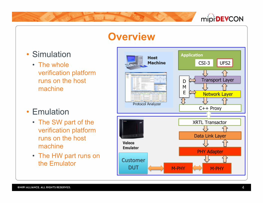
Overview • Simulation
• The whole verification platform runs on the host machine
• Emulation • The SW part of the
verification platform runs on the host machine
• The HW part runs on the Emulator
4
Transport Layer
Network Layer
Data Link Layer
PHY Adapter
D M E
Applica'on
C++ Proxy
XRTL Transactor
CSI-3 UFS2
M-PHY M-PHY

Co-Design • Network, DME, Transport, MIPI
CSI-3 and UFS2 layers are native C++ software layers
• Communication between SW and HW is through a transaction-based methodology based on SCE-MI 2.0 • C++ Proxy • XRTL transactor
• Middle-out methodology • Started with Data link layer and Network
layer first.
5
Transport Layer
Network Layer
Data Link Layer
PHY Adapter
D M E
Applica'on
C++ Proxy
XRTL Transactor
CSI-3 UFS2
M-PHY

Co-Design int UniProMemoryXactor_sc::WriteTransaction(u_int8_t *pBuf, u_int16_t wBytesCount, bool IsBlocking)
{ …
UniProMemoryWrite((svBitVecVal *)pTxBuf,(int)wBytesCount, (IsBlocking)?1:0); if (IsBlocking) { wait(Done);
}; … }
6
function void UniProMemoryWrite(input bit [COMODEL_BUF_SIZE-1:0] Buf, int BytesCount, int IsBlocking); WrIsBlock = IsBlocking; WrDataWordsCounts = ((BytesCount/(DATA_WIDTH/8)) + ((BytesCount%(DATA_WIDTH/8))?1:0));
WrBytesOfLastWord = BytesCount - (WrDataWordsCounts-1)*(DATA_WIDTH/8); WrLastBe = (WrBytesOfLastWord == 8 ) ? 8'hFF: (WrBytesOfLastWord == 7 ) ? 8'h7F: (WrBytesOfLastWord == 6 ) ? 8'h3F: (WrBytesOfLastWord == 5 ) ? 8'h1F: (WrBytesOfLastWord == 4 ) ? 8'h0F: (WrBytesOfLastWord == 3 ) ? 8'h07: (WrBytesOfLastWord == 2 ) ? 8'h03: (WrBytesOfLastWord == 1 ) ? 8'h01:
8'hFF;
for(int i =0 ; i< WrDataWordsCounts; i = i + 1 ) begin WrBuf[i] = Buf[(DATA_WIDTH)*i +: DATA_WIDTH]; end ->e_StartWr; endfunction;
C++proxyun;medso?waremodel
XRTLcounterpart
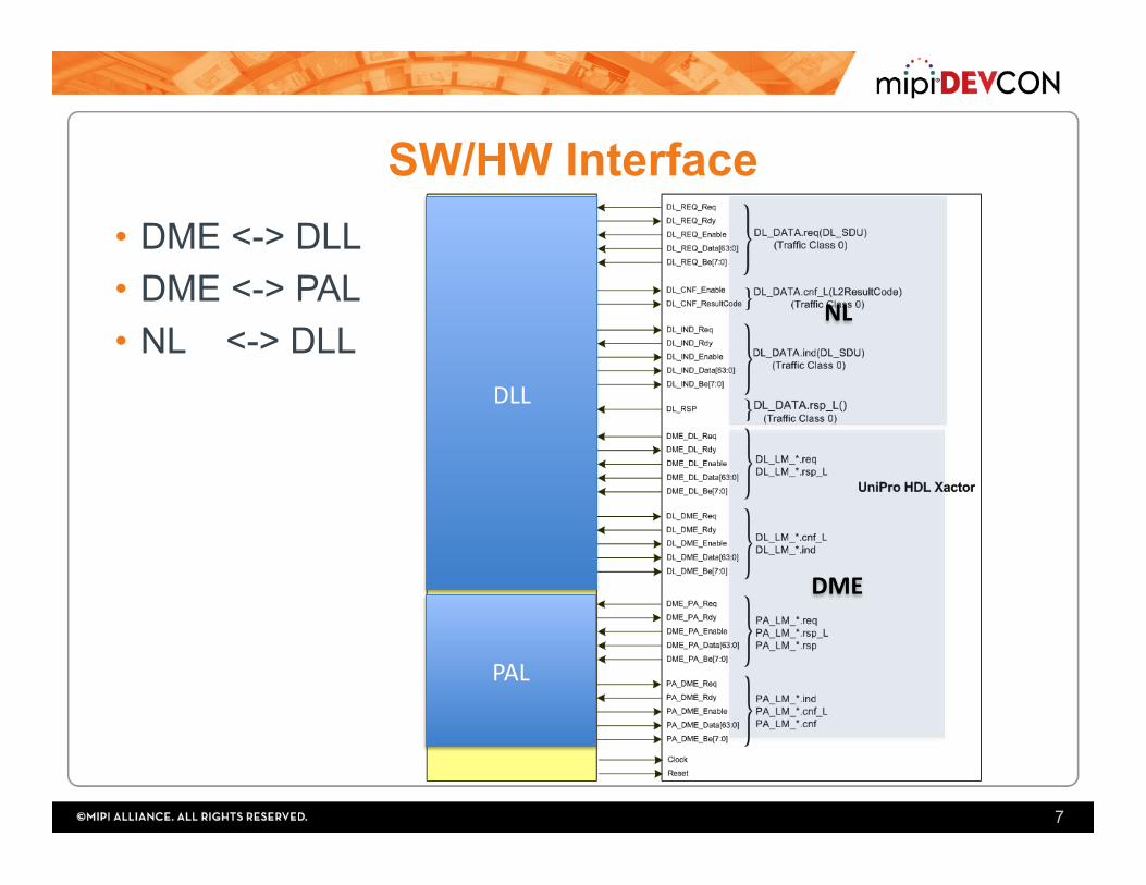
SW/HW Interface
7
• DME <-> DLL • DME <-> PAL • NL <-> DLL
NL
DME
DLL
PAL

SW/HW Interface (DME/NL SAPs)
8
DataSymbol# Bitfields
0
[15:0] DME_SAPopcode [31:16] GenSelectorIndexorSelectorIndex [47:32] MIBaUributeorGenMIBaUribute [55:48] ResultCode:usedforGenericErrorCode,ConfigResultCodeandPowerChangeResultCode,
DLErrorCode [56] AUrSetType [57] ResetLevel [58] PAResult [59] PHYDirec;on
1 [31:0] MIBvalue 2,3,4 PAPowerModeUserData

SW/HW Interface (NL SAPs)
9

UFS/CSI <-> UniPro Interface
10

Design Considerations • Implementing DME/NL/TL/UFS/CSI in SW
• flexibility • faster implementation
• Implementing PAL/DLL in RTL • Better overall performance (Minimize communication overhead)
• Bulks of data are grouped in DL and sent once to NL so better be in HW for performance
• Timers are in DL and PAL, can’t be done accurately in SW
• XRTL tasks have timeout mechanism to avoid blocking the calling SW side
11

HW Design Considerations • Full separation of data and control buses. Full
separation of TX and RX data buses • All layer attributes are implemented in a memory
module • Allows fast initialization of UniPro IP • Serves well in monitoring the layer attributes using the Protocol
Analyzer
• Abstract number of active lanes from the internal data bus through the use of lane distribution/merging logic
• 64 bits fixed Internal data bus (4 lanes of 16-bits each) • Merge PA_DATA and PA_ESCDATA into one SAP with
control flag
12

System Verification • UniPro level
• MIPI M-PHY already tested in a separate testing env (UVM based) • Block/Layer (UVM verification env.)
• PAL vs TLM models • DLL vs TLM models
• Integration • DLL/PAL/PHY vs TLM models in UVM env (HW) • UniPro (NL, TL, DLL, PAL, M-PHY) back to back (SW&HW)
• System level • UFS device vs UFS host UVM test env • UFS device vs UFS Host invoking guest OS
13

Layer testing (PAL, DLL)
14
DMEAgent
ULAgent
Layer X DUT
DME i/f
ULi/f
LL i/fDMEAgent
ULAgentTLM Refmodel
SB
seq
seq
seq
seq
Virtualseq
- UVM Based - Same architecture for PAL/DLL testing env
- X Agent represents the layer completely and reused as TLM ref model
- Ref model should be in sync with the DUT
monitor
driversqr
sqr
XAgent

PAL Verification Env.
15
PALDUT
DME i/f
DLL i/f
M-M
PALTLM
Model
monitor
driversqr
sqr
RMMI
RMMI IF
PALAgent

HW Integration Env. • Connect PAL and DLL UVM env back to back • In PAL env:
• Replace UL agent (dummy DLL) with a connection to the DLL verification env
• Direct all DLL communications to the PAL agent • Dummy DLL agent at the DUT side is passive and only monitors
PAL-DLL interface
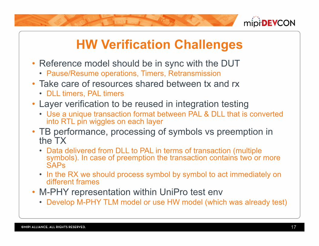
HW Verification Challenges • Reference model should be in sync with the DUT
• Pause/Resume operations, Timers, Retransmission • Take care of resources shared between tx and rx
• DLL timers, PAL timers • Layer verification to be reused in integration testing
• Use a unique transaction format between PAL & DLL that is converted into RTL pin wiggles on each layer
• TB performance, processing of symbols vs preemption in the TX • Data delivered from DLL to PAL in terms of transaction (multiple
symbols). In case of preemption the transaction contains two or more SAPs
• In the RX we should process symbol by symbol to act immediately on different frames
• M-PHY representation within UniPro test env • Develop M-PHY TLM model or use HW model (which was already test)
17
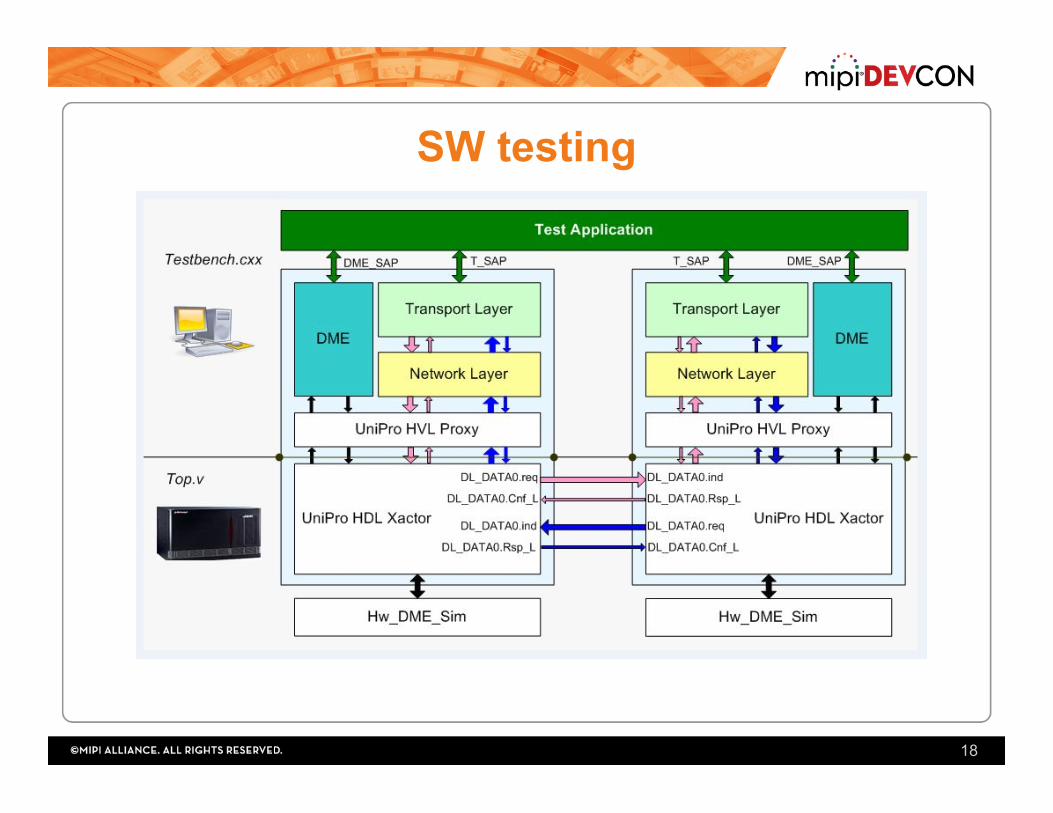
SW testing
18
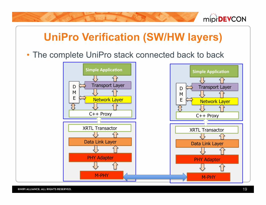
UniPro Verification (SW/HW layers) • The complete UniPro stack connected back to back
19
Transport Layer
Network Layer
Data Link Layer
PHY Adapter
D M E
SimpleApplica'on
C++ Proxy
XRTL Transactor
M-PHY
Transport Layer
Network Layer
Data Link Layer
PHY Adapter
D M E
SimpleApplica'on
C++ Proxy
XRTL Transactor
M-PHY

System Verification (UVM Env)
20
UFSAPPBFM+AXI
DriverVC
STIM
ULUS
UFSHost
M-PHY
DeviceUniPro
M-PHY
RMMI
DeviceUniProSW
UFSAppl.
(SC)TestbenchIPC
DPI
UNIPRO
HostCPortMonitor
MS
SMRx
Tx
ufs_host_core_top
ProtocolAnalyzer(UniPro/UFS)

VM-QEMU/Host Based Solution + UFS Driver
21
SwDriverSetup
HWSetup
UFSHC

DEBUGGING Protocol Analyzer
22

Debugging • Complex protocol layers (hard to spot bugs) • Specific attributes for each layer • Should trace HW/SW parts to spot issues
• Developed an in-house debugging tool “Protocol Analyzer” • Traces and Monitors:
• RMMI traffic • UniPro SAPs • UFS2 commands
23

Virtual UFS2: Snapshot
24
UFS device received a NOP OUT command from the host(32 bytes)
UFS replies with a NOP IN command to the host(32 bytes)

Virtual UFS2: SAP Tracing • Selecting the PACP_* SAP, the decoder window
shows the fields contents of PACP frames

Virtual UFS2: SAP Tracing • Selecting the DL_DATA_IND SAP, the
decoder window shows the raw data of the UniPro packet received by host

Virtual UFS2: SAP Tracing • Selecting the UFS_* SAP, the decoder
window shows the fields contents of the ULPI, each ULPI has a decoder

Virtual UFS2: Snapshot
s, Presentation Title, Month Year 28
SAP Tracing
M-PHY tracing
SAP Decoding
sessions
Session Info.
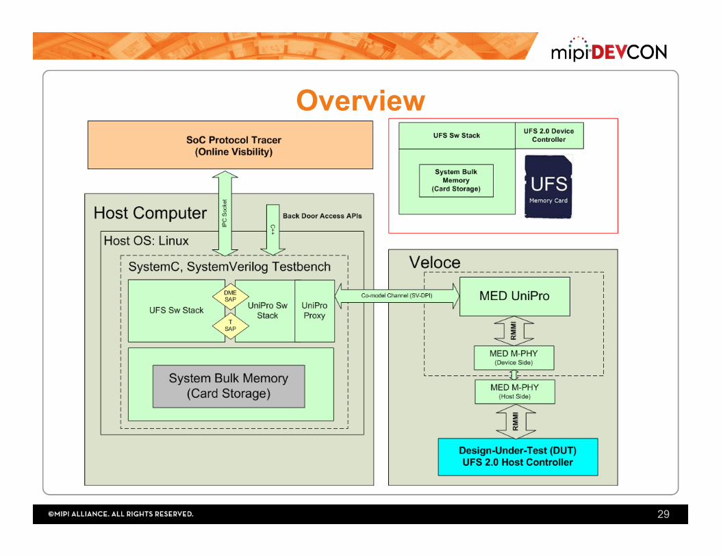
Overview
29

Overview
30

HW Integration Env.
PALDUT
DME i/f
DLL i/f
M-M
PALTLM
Model
RMMI IF
RMMI DLLDUT
DME i/f
NL i/f
PAL i/f
DMEAgent DME
Agent
ToDMESB
ToDMESB
DMEreq
DLLTLM
Model DMEreq
DummyNLAgent
req/res
conf/ind
DummyDLLAgent(passive)
DLLAgent
DummyNLAgent
DMEAgent
mon
drvsqr
sqr
DMEAgent
PALAgentmon
drvsqr
sqr
PA->DLSAPs
DL->PASB
DL->PASAPs
DL->PASAPs
DMESB(PA)
DME
DMESB(DL)
NLSB
ToNLSB
DLControlSB

Virtual UFS2: Multi-View
• Multi-View allows the user to open two sessions side by side to compare.
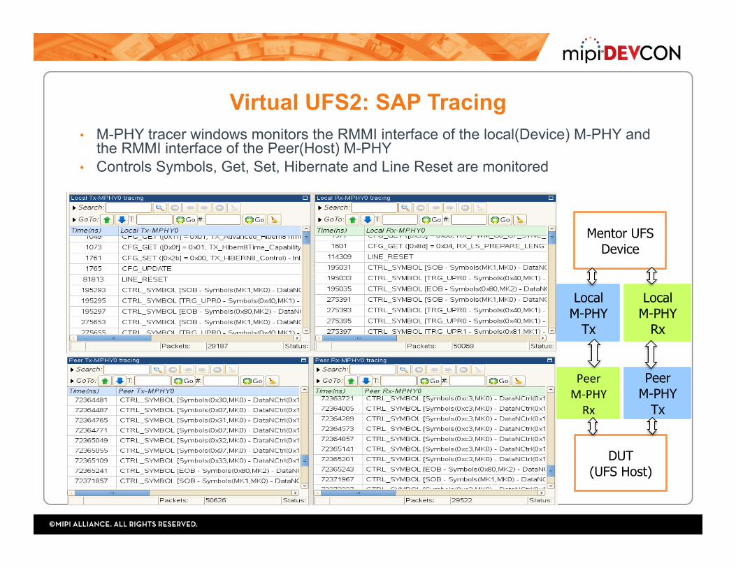
Virtual UFS2: SAP Tracing
PeerM-PHYRx
Peer M-PHY
Tx
Local M-PHY
Tx
Local M-PHY
Rx
Mentor UFS Device
DUT (UFS Host)
• M-PHY tracer windows monitors the RMMI interface of the local(Device) M-PHY and the RMMI interface of the Peer(Host) M-PHY
• Controls Symbols, Get, Set, Hibernate and Line Reset are monitored

Virtual UFS2: Session Configurations • Control/configure the Virtual UFS2
device before running the emulation
Data Link Layer
PHY Adapter
Transport Layer Network Layer
UFS Application
soc_tracerenables/disablesverilogModules(DL/PAStatemachinesMonitor.v)usingDPIexportcallat;me0ns
SM Monitor.v
SMMonitor.v