Minor Losses - University of Memphis · 3 Minor Losses ! Rather than develop a detailed energy loss...
16
1 Civil Engineering Hydraulics Minor Losses Minor Losses Up to this point, all we have considered is pipes conveying flows The pipes have been a constant cross section and have not had to go around anything, turn any corners, or really change flow direction Minor Losses 2 Wednesday, October 17, 2012
-
Upload
truongthien -
Category
Documents
-
view
221 -
download
4
Transcript of Minor Losses - University of Memphis · 3 Minor Losses ! Rather than develop a detailed energy loss...

1
Civil Engineering Hydraulics
Minor Losses
Minor Losses
¢ Up to this point, all we have considered is pipes conveying flows
¢ The pipes have been a constant cross section and have not had to go around anything, turn any corners, or really change flow direction
Minor Losses 2 Wednesday, October 17, 2012

2
Minor Losses
¢ In practice, that usually isn’t so therefore we have to consider the energy losses that these changes in direction cost
¢ In addition to changes in direction, the volumetric flow rate is often controlled by adjusting some sort of flow control device, most commonly a value.
Minor Losses 3 Wednesday, October 17, 2012
Minor Losses
¢ Any sort of change in the pattern of the flow (the velocity profile) will result in a change (decrease) of the energy of the flow.
¢ Think of it as taking a pack of cards and shuffling it and then having to rearrange the deck.
Minor Losses 4 Wednesday, October 17, 2012

3
Minor Losses
¢ Rather than develop a detailed energy loss description for each type of valve and fitting, there is a characteristic value that we use.
Minor Losses 5 Wednesday, October 17, 2012
Minor Losses
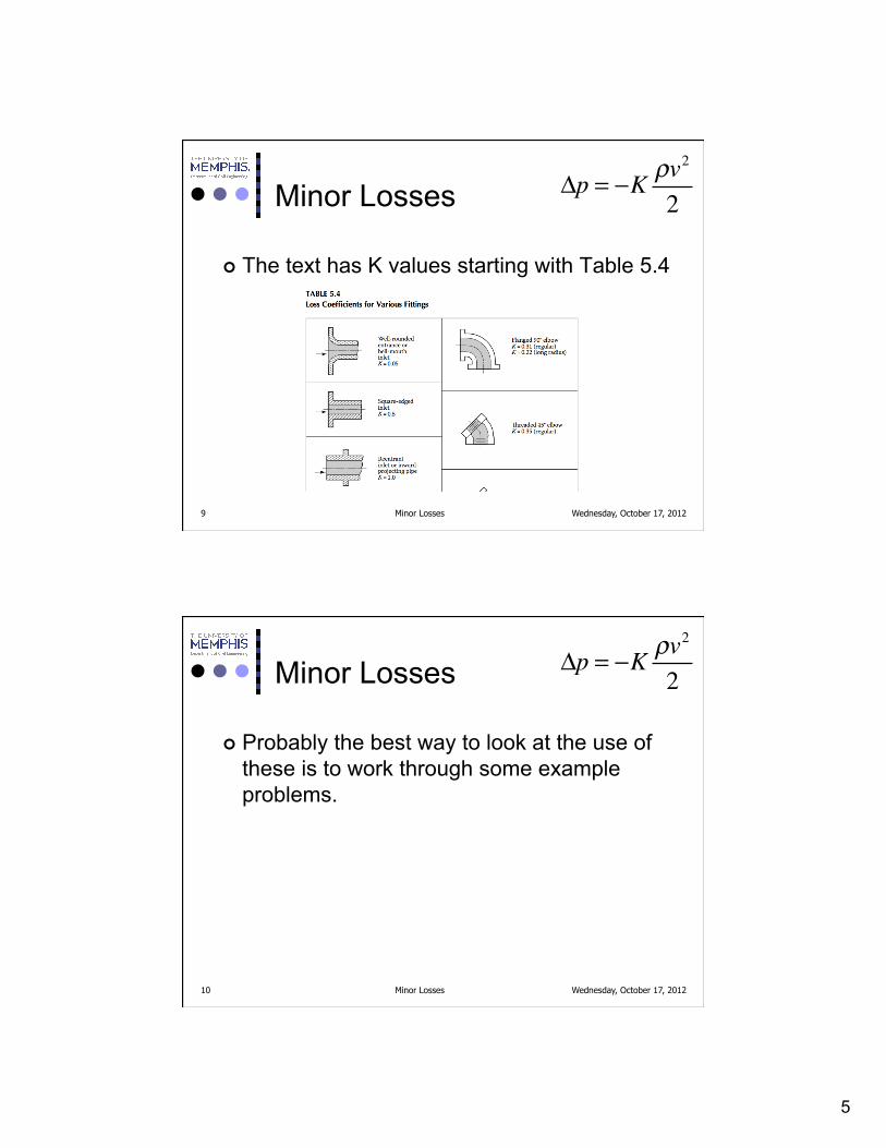
¢ The pressure drop across or through a fitting or valve is given by
Minor Losses 6
Δp = −K ρv2
2
Wednesday, October 17, 2012

4
Minor Losses
¢ The v is the average velocity at the entrance to the fitting or valve
¢ K is the loss coefficient for the fitting or valve
Minor Losses 7
Δp = −K ρv2
2
Wednesday, October 17, 2012
Minor Losses
¢ K values for common piping elements are available from most manufacturers as well as in general tables
¢ You may also see the symbol ξ used in place of K
Minor Losses 8
Δp = −K ρv2
2
Wednesday, October 17, 2012
5
Minor Losses
¢ The text has K values starting with Table 5.4
Minor Losses 9
Δp = −K ρv2
2
Wednesday, October 17, 2012
Minor Losses
¢ Probably the best way to look at the use of these is to work through some example problems.
Minor Losses 10
Δp = −K ρv2
2
Wednesday, October 17, 2012

6
Minor Losses
Minor Losses 11
Δp = −K ρv2
2
Wednesday, October 17, 2012
Minor Losses
Minor Losses 12
Δp = −K ρv2
2
Wednesday, October 17, 2012

7
Minor Losses
Minor Losses 13
Δp = −K ρv2
2
Wednesday, October 17, 2012
Minor Losses
Minor Losses 14
Δp = −K ρv2
2
Wednesday, October 17, 2012

8
Minor Losses
Minor Losses 15
Δp = −K ρv2
2
Wednesday, October 17, 2012
Minor Losses
¢ Now we can write the Bernoulli equation and include the loss terms between points 1 and 2
Minor Losses 16
p1
ρg+
v12
2g+ z1+
fitting lossesρg
+ friction losses
ρg =
p2
ρg+
v22
2g+ z2
Remember that the losses have a negative sign included in their calculationThe losses are divided by rho g because they are calculated in termsof pressure.
Wednesday, October 17, 2012

9
Minor Losses
¢ And rearranging to isolate the pressure change
Minor Losses 17
p1 − p2= +ρv2
2
2+ ρgz2 −
ρv12
2− ρgz1
− fitting losses( ) − friction losses( )
Wednesday, October 17, 2012
Minor Losses
¢ Substituting what we know already
Minor Losses 18
p1 − p2= 870
kgm3
⎛⎝⎜
⎞⎠⎟
1.697ms
⎛⎝⎜
⎞⎠⎟
2
2+ 870
kgm3
⎛⎝⎜
⎞⎠⎟
9.81ms2
⎛⎝⎜
⎞⎠⎟
2.7m( )
−870
kgm3
⎛⎝⎜
⎞⎠⎟
0.763ms
⎛⎝⎜
⎞⎠⎟
2
2− 870
kgm3
⎛⎝⎜
⎞⎠⎟
9.81ms2
⎛⎝⎜
⎞⎠⎟
3.0m( ) - fitting losses( ) - friction losses( )
Wednesday, October 17, 2012

10
Minor Losses
¢ Substituting what we know already
Minor Losses 19
p1 − p2= 24.29kPa − 25.85kPa
- − K ρv 2
2∑⎛⎝⎜
⎞⎠⎟
- −f12L12
Dh12
v122
2g−
f8L8
Dh8
v82
2g
⎛
⎝⎜
⎞
⎠⎟
Wednesday, October 17, 2012
Minor Losses
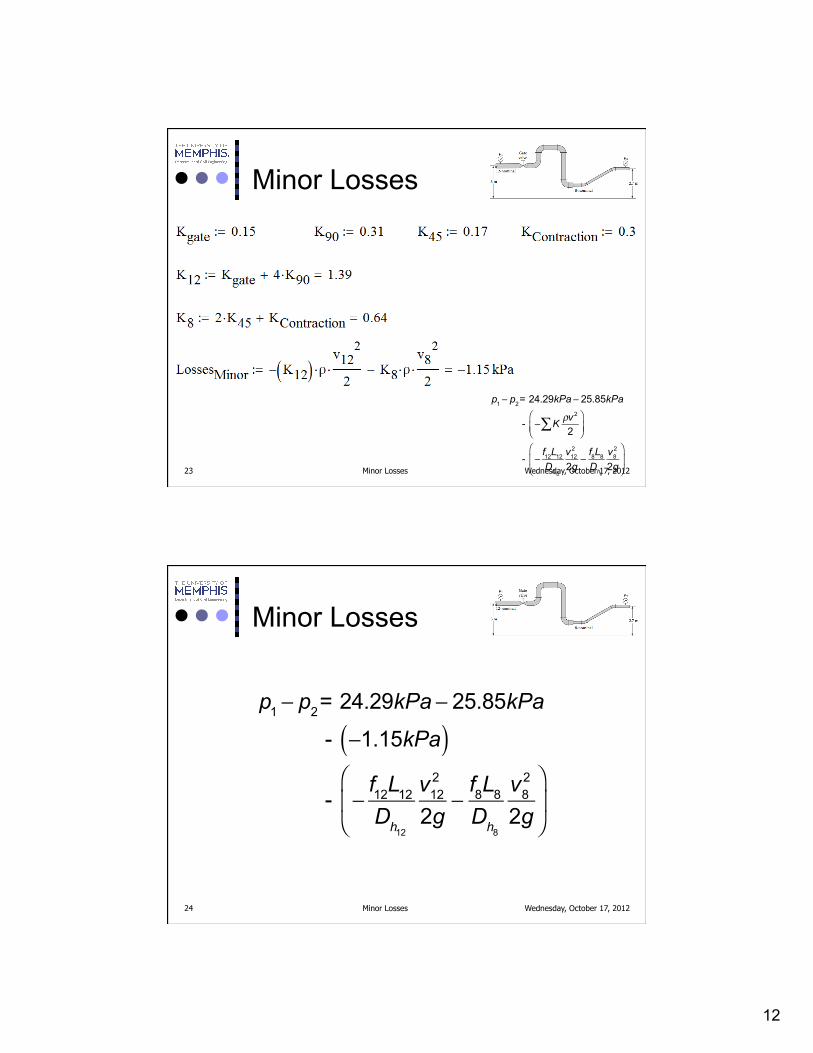
¢ Moving from left to right we have a gate valve, a 90 degree elbow, a 90 degree elbow, a 90 degree elbow, a 90 degree elbow, a reducing connection, a 45 degree elbow, and a 45 degree elbow
Minor Losses 20
p1 − p2= 24.29kPa − 25.85kPa
- − K ρv 2
2∑⎛⎝⎜
⎞⎠⎟
- −f12L12
Dh12
v122
2g−
f8L8
Dh8
v82
2g
⎛
⎝⎜
⎞
⎠⎟
Wednesday, October 17, 2012

11
Minor Losses
¢ The problem states that all the elbows are standard and flanged so we can find the K values from Table 5-4
Minor Losses 21
K90 = 0.31K45 = 0.35Kgate = 0.15 (assume that the gate valve is open)Kcontraction = 0.3
Wednesday, October 17, 2012
Minor Losses
¢ Take care to use the velocity in the section of the pipe that the fitting is in
¢ You may combine the K values for fittings in the same pipe (if the velocity is constant)
Minor Losses 22
K90 = 0.31K45 = 0.35Kgate = 0.15 (assume that the gate valve is open)Kcontraction = 0.3
Wednesday, October 17, 2012
12
Minor Losses
Minor Losses 23
p1 − p2= 24.29kPa − 25.85kPa
- − K ρv 2
2∑⎛⎝⎜
⎞⎠⎟
- −f12L12
Dh12
v122
2g−
f8L8
Dh8
v82
2g
⎛
⎝⎜
⎞
⎠⎟
Wednesday, October 17, 2012
Minor Losses
Minor Losses 24
p1 − p2= 24.29kPa − 25.85kPa
- −1.15kPa( )
- −f12L12
Dh12
v122
2g−
f8L8
Dh8
v82
2g
⎛
⎝⎜
⎞
⎠⎟
Wednesday, October 17, 2012

13
Minor Losses
Minor Losses 25 Wednesday, October 17, 2012
Minor Losses
Minor Losses 26
p1 − p2= 24.29kPa − 25.85kPa
- −1.15kPa( ) - −3.39kPa( )
Wednesday, October 17, 2012

14
Minor Losses
Minor Losses 27 Wednesday, October 17, 2012
Example 5.9
¢ A water tank is fitted with a drain and outlet pipe as sketched in Figure 5.24. The system has 82 ft of cast iron pipe of 1 1/2-nominal diameter. Determine the flow rate through the pipe. All fittings are threaded and regular.
Wednesday, October 17, 2012 Minor Losses 28
15
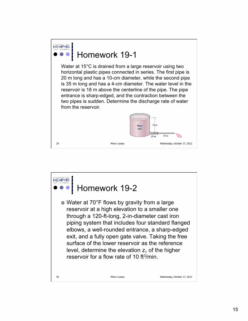
Homework 19-1 Water at 15°C is drained from a large reservoir using two horizontal plastic pipes connected in series. The first pipe is 20 m long and has a 10-cm diameter, while the second pipe is 35 m long and has a 4-cm diameter. The water level in the reservoir is 18 m above the centerline of the pipe. The pipe entrance is sharp-edged, and the contraction between the two pipes is sudden. Determine the discharge rate of water from the reservoir.
Minor Losses 29 Wednesday, October 17, 2012
Homework 19-2 ¢ Water at 70°F flows by gravity from a large
reservoir at a high elevation to a smaller one through a 120-ft-long, 2-in-diameter cast iron piping system that includes four standard flanged elbows, a well-rounded entrance, a sharp-edged exit, and a fully open gate valve. Taking the free surface of the lower reservoir as the reference level, determine the elevation z1 of the higher reservoir for a flow rate of 10 ft3/min.
Minor Losses 30 Wednesday, October 17, 2012

16
Homework 19-3
Minor Losses 31 Wednesday, October 17, 2012