MinnRock Design and Canister Layout 11-20-09. Team members Bryce Schaefer (team coordinator)- AEM...
19
MinnRock Design and Canister Layout 11-20-09
-
Upload
bennett-simmons -
Category
Documents
-
view
213 -
download
0
Transcript of MinnRock Design and Canister Layout 11-20-09. Team members Bryce Schaefer (team coordinator)- AEM...
MinnRock Design and Canister Layout
11-20-09
Team members
• Bryce Schaefer (team coordinator)- AEM• Cameron Japuntich- AEM• Liz Sefkow- ME• Mitch Andrus- ME• Chris Larson- ME• Phillip Hoffman- EE

Mission Objective• The MinnRock II board is a flight characterization board similar to the
board that flew last year, the MinnRock (I) project. We aim to look at many aspects of the rocket’s flight, including: spin rate, 3D acceleration, light intensity, pressure, and temperature, and the Earth’s magnetic field as a function of the rocket’s altitude
• Spin rate with a single light sensor• 3D acceleration (x, y, z) as a function of time• The inner pressure and temperature within the canister• The Earth’s magnetic field as a function of the rocket’s altitude• The trajectory of the rocket using a GPS
Other objectives• Capture still pictures while in flight using a camera, and observe the
possibility of switching to video mid-flight.
Expected Results
• We expect to be able to compare data from this years flight to our own existing data
• We wish to answer any questions regarding the use of a GPS or (video)camera


Solid Works images
• We have a full layout of our solid works slides• This layout may change due to center of mass
issues, and or the implementation of wiring• The next few slides show our payload first as a
whole, then separated into parts to show details
• Some components are shown as simple blocks because they are being made in-house and have not yet been created
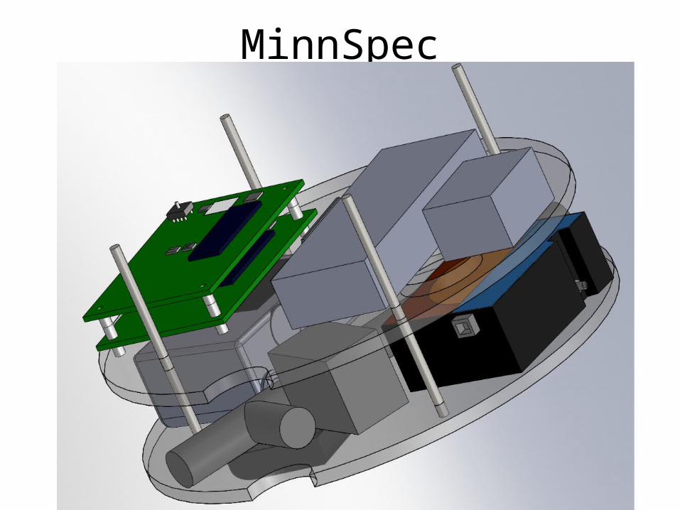
MinnSpec
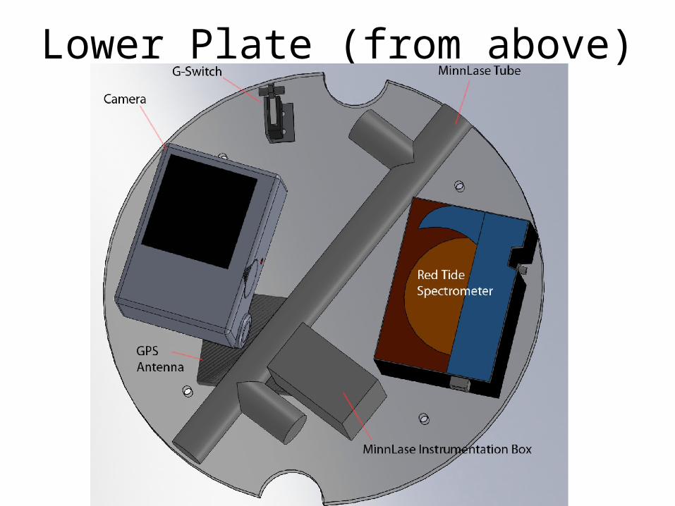
Lower Plate (from above)

Lower Plate (from below)

Upper plate (from above)
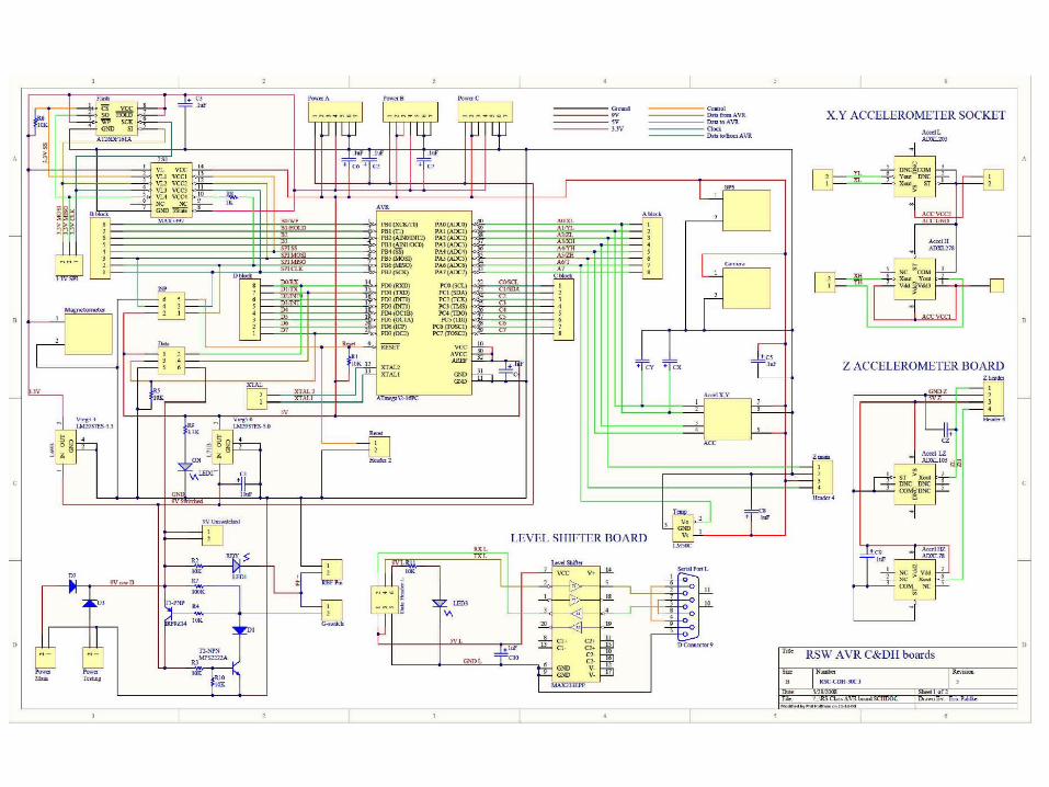
Electrical Schematics
• We have modified the schematics from RockOn! In order to integrate a camera, GPS, and magnetometer
• On the next slide is the modified schematic of the AVR boards

Subsystems overview
• The MinnRock II portion of the payload is split up into three specific areas:- Camera- GPS- AVR boards
• Each of the subsystems will be observed in further detail on the next slides

Camera
• We have recently talked with Wyoming and have decided that the optimal route for us to go is to have them utilize the optical port and take care of the camera, while we utilize the atmospheric ports with our spectroscopy experiments. We will therefore be “sharing” pictures and optical data.
• This means we will effectively be removing our camera from the experiment
• We will likely cut a space out of our tray in order to allow Wyoming ample space to center their camera on the window
• The question of structural integrity has been addressed with the addition of a “cut” in our plates, but any danger has been dismissed due to the presence of our steel plates

GPS
• New focus has been placed on the GPS in order to get it fully operational while integrated in our canister
• The antenna needs to be near the optical port, and has therefore been “hung” from our bottom tray in order to place it as close as possible to the port, and also to eliminate any interference from the steel trays
• This plan has been relayed to Wyoming in order to avoid the antenna bumping into the camera
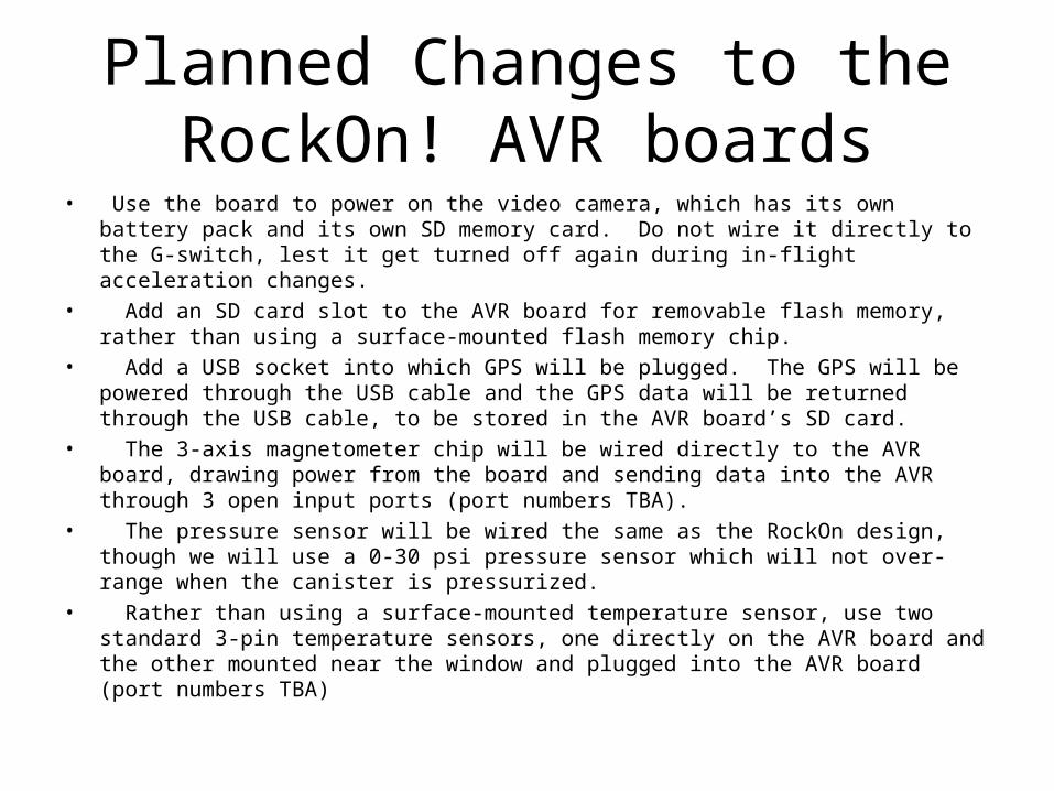
Planned Changes to the RockOn! AVR boards
• Use the board to power on the video camera, which has its own battery pack and its own SD memory card. Do not wire it directly to the G-switch, lest it get turned off again during in-flight acceleration changes.
• Add an SD card slot to the AVR board for removable flash memory, rather than using a surface-mounted flash memory chip.
• Add a USB socket into which GPS will be plugged. The GPS will be powered through the USB cable and the GPS data will be returned through the USB cable, to be stored in the AVR board’s SD card.
• The 3-axis magnetometer chip will be wired directly to the AVR board, drawing power from the board and sending data into the AVR through 3 open input ports (port numbers TBA).
• The pressure sensor will be wired the same as the RockOn design, though we will use a 0-30 psi pressure sensor which will not over-range when the canister is pressurized.
• Rather than using a surface-mounted temperature sensor, use two standard 3-pin temperature sensors, one directly on the AVR board and the other mounted near the window and plugged into the AVR board (port numbers TBA)
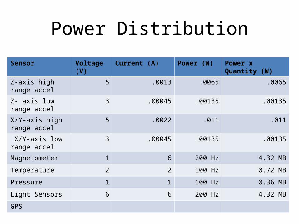
Power Distribution
Sensor Voltage (V) Current (A) Power (W) Power x Quantity (W)
Z-axis high range accel
5 .0013 .0065 .0065
Z- axis low range accel
3 .00045 .00135 .00135
X/Y-axis high range accel
5 .0022 .011 .011
X/Y-axis low range accel
3 .00045 .00135 .00135
Magnetometer 1 6 200 Hz 4.32 MB
Temperature 2 2 100 Hz 0.72 MB
Pressure 1 1 100 Hz 0.36 MB
Light Sensors 6 6 200 Hz 4.32 MB
GPS
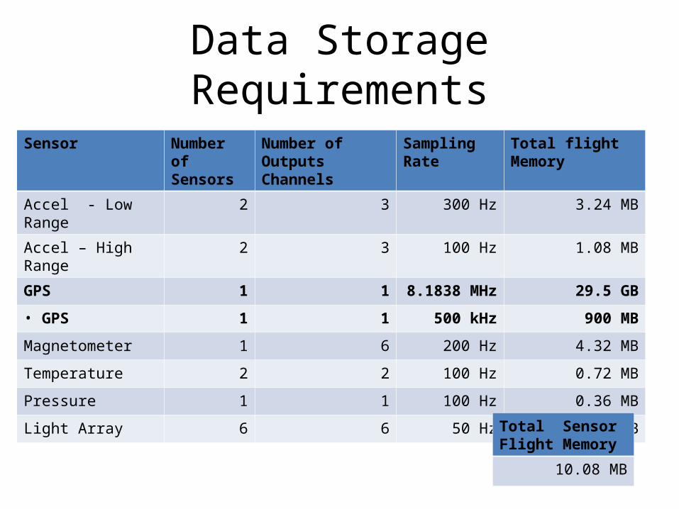
Data Storage Requirements
Sensor Number of Sensors
Number of Outputs Channels
Sampling Rate Total flight Memory
Accel - Low Range 2 3 300 Hz 3.24 MB
Accel – High Range 2 3 100 Hz 1.08 MB
GPS 1 1 8.1838 MHz 29.5 GB
• GPS 1 1 500 kHz 900 MB
Magnetometer 1 6 200 Hz 4.32 MB
Temperature 2 2 100 Hz 0.72 MB
Pressure 1 1 100 Hz 0.36 MB
Light Array 6 6 50 Hz 1.08 MB
Total Sensor Flight Memory
10.08 MB

Additional Comments/Concerns
• We would still like to get a copy of the AVR board schematics that is modifiable to fit our experiment
• We will constantly be updating our solid models to fit the new design constrictions