MINISTRY OF ELECTRICITY -...
250
MINISTRY OF ELECTRICITY IRAQ SUPERGRID PROJECTS 400/132 KV GIS SUBSTATIONS VOLUME 3 TECHNICAL SCHEDULES JANUARY 2007
Transcript of MINISTRY OF ELECTRICITY -...

MINISTRY OF ELECTRICITY
IRAQ SUPERGRID PROJECTS 400/132 KV GIS SUBSTATIONS VOLUME 3 TECHNICAL SCHEDULES JANUARY 2007

400kV GIS SUBSTATION – VOLUME 3
LIST OF REVISIONS
Current Rev.
Date Page affected
Prepared by
Checked by (technical)
Checked by (quality
assurance)
Approved by
1 2 3 4 5
19.11.04 18.03.05 Aug 05 Oct 05 Jan 07
ALL ALL ALL ALL ALL
SSA JK/MH
JK MH/MH JK/MH
JW JK/MH JK/MH
JW JW
JW JW JW JW JW
JW JW JW JW JW
REVISION HISTORY
3 Aug 05 ALL Updated with MOE comments and general alignment across volumes.
4 Oct 05 ALL Specification split into GIS and AIS versions. Capacitor specification rationalised. Impulse withstand and Power frequency withstand values reviewed in accordance with IEC 60694. Details for 11 kV (Tertiary) shunt reactors added.
5 Jan 07 ALL General review

400kV GIS SUBSTATION – VOLUME 3
CONTENT SHEET
VOLUME 1 TECHNICAL SPECIFICATION – PLANT VOLUME 2 TECHNICAL SPECIFICATION & SCHEDULES – CIVIL WORKS VOLUME 3 TECHNICAL SCHEDULES – PLANT

400kV GIS SUBSTATION – VOLUME 3
CONTENTS
Page No.
SCHEDULE A - MILESTONES FOR THE PURPOSE OF PAYMENT AND HANDOVER TO THE CLIENT ............................................................ A.1
SCHEDULE B - TIME PERIODS FOR PROCUREMENT, DESIGN, MANUFACTURE, INSPECTION, TESTING, DELIVERY, INSTALLATION, COMMISSIONING AND HANDOVER ..................... B.1
SCHEDULE C - MANUFACTURERS AND PLACES OF MANUFACTURE, TESTING AND INSPECTION..............................................................C.1
SCHEDULE C1 - 400 KV GAS INSULATED SWITCHGEAR..........................................C.1
SCHEDULE C2 - 400 KV AIS OUTDOOR SWITCHGEAR .............................................C.2
SCHEDULE C3 - 132 KV GAS INSULATED SWITCHGEAR..........................................C.2
SCHEDULE C4 - 132 KV AIS OUTDOOR SWITCHGEAR .............................................C.3
SCHEDULE C5 - 11 KV METALCLAD SWITCHGEAR...................................................C.4
SCHEDULE C6 - TRANSFORMERS REACTORS AND AUXILIARY PLANT.................C.4
SCHEDULE C7 - LV SERVICES EQUIPMENT...............................................................C.5
SCHEDULE C8 - CABLES ..............................................................................................C.5
SCHEDULE C9 - SUBSTATION CONTROL AND PROTECTION SYSTEMS`...............C.6
SCHEDULE D - TECHNICAL PARTICULARS ..............................................................D.1
SCHEDULE D1 - 400 KV GAS INSULATED SWITCHGEAR........................................D1.1
SCHEDULE D2 - 400 KV OPEN TERMINAL SWITCHGEAR .......................................D2.1
SCHEDULE D3 - 132 KV GAS INSULATED SWITCHGEAR........................................D3.1
SCHEDULE D4 - 132 KV OPEN TERMINAL SWITCHGEAR .......................................D4.1
SCHEDULE D5 - 11 KV (TERTIARY) METALCLAD SWITCHGEAR............................D5.1
SCHEDULE D6 - CRANE FOR GIS BUILDING ............................................................D6.1
SCHEDULE D7 - 400/132 KV POWER TRANSFORMERS ..........................................D7.1
SCHEDULE D8 - 400 KV SHUNT REACTORS.............................................................D8.1
SCHEDULE D9 - EARTHING TRANSFORMERS (11 KV TERTIARY) .........................D9.1
SCHEDULE D10 - AUXILIARY TRANSFORMERS (11 KV TERTIARY).......................D10.1

400kV GIS SUBSTATION – VOLUME 3
CONTENTS - Continued
Page No.
SCHEDULE D11 - CAPACITORS (11 KV TERTIARY) .................................................D11.1
SCHEDULE D12 - 11 KV (TERTIARY) SHUNT REACTORS .......................................D12.1
SCHEDULE D13 - LVAC SWITCHGEAR......................................................................D13.1
SCHEDULE D14 - DC SYSTEM....................................................................................D14.1
SCHEDULE D15 - 220 V AC UNINTERRUPTIBLE POWER SUPPLY.........................D15.1
SCHEDULE D16 - 132/11 KV POWER CABLES ..........................................................D16.1
SCHEDULE D17 - LV CABLES .....................................................................................D17.1
SCHEDULE D18 - PROTECTION SYSTEM .................................................................D18.1
SCHEDULE D19 - SUBSTATION CONTROL SYSTEM ...............................................D19.1
SCEHDULE D20 - CONTROL, OPERATION, INDICATION AND ALARM CIRCUITS .D20.1
SCHEDULE D21 - BUSHINGS......................................................................................D21.1
SCHEDULE E - TECHNICAL DOCUMENTATION/DRAWINGS AND OPERATING AND MAINTENANCE INSTRUCTIONS.............................................. E.1
SCHEDULE E1 - DRAWINGS ISSUED WITH THE TENDER ........................................ E.1
SCHEDULE E2 - DRAWINGS REQUIRED WITH TENDER........................................... E.2
SCHEDULE E3 - CONTRACT DRAWING REQUIREMENTS ........................................ E.3
SCHEDULE E4 - CONTRACTOR’S SUBMITTALS - DRAWING AND DESIGN DATA.. E.5
SCHEDULE E5 - INSTALLATION AND MAINTENANCE INSTRUCTIONS ................... E.7
SCHEDULE E6 - FINAL RECORDS ............................................................................... E.7
SCHEDULE F - DEVIATIONS FROM THE TECHNICAL SPECIFICATION ................. F.1
SCHEDULE G - QUANTITIES AND PRICES ................................................................G.1
SCHEDULE J1 - RECOMMENDED SPARES ...............................................................J1.1
SCHEDULE J2 - SPECIAL TOOLS, TEST EQUIPMENT..............................................J2.1
SCHEDULE J3 - TRANSFORMERS AND REACTORS QUANTITIES AND PRICES FOR SPARE PARTS..........................................................................J3.1
SCHEDULE K - BUILDING SERVICES ........................................................................ K.1

400kV GIS SUBSTATION – VOLUME 3
SCHEDULE L - HEATING, VENTILATION AND AIR CONDITIONING.........................L.1

400kV GIS SUBSTATION – VOLUME 3
SCHEDULE A
MILESTONES FOR THE PURPOSE OF PAYMENT AND HANDOVER TO THE CLIENT

A.1 400kV SUBSTATION – VOLUME 3
SCHEDULE A - MILESTONES FOR THE PURPOSE OF PAYMENT AND HANDOVER TO THE CLIENT
(Information to be provided with Tender) The Tenderer is to indicate all milestones identified within the programme for the works as defined in this Project Specification. The milestones should align with those included in the priced (fixed sum) activity schedule.
Item No
Description Section

400kV GIS SUBSTATION – VOLUME 3
SCHEDULE B
TIME PERIODS FOR PROCURMENT, DESIGN, MANUFACTURE, INSPECTION, TESTING, DELIVERY, INSTALLATION, COMMISSIONING AND HANDOVER

B.1 400kV GIS SUBSTATION – VOLUME 3
SCHEDULE B - TIME PERIODS FOR PROCUREMENT, DESIGN, MANUFACTURE, INSPECTION, TESTING, DELIVERY, INSTALLATION, COMMISSIONING AND
HANDOVER
(Information to be provided with Tender. All time periods are weeks from date of Notice to Proceed)
Description
Time within which:
1 All arrangement and equipment drawings shall be submitted for approval
2 All schemes and functional drawings shall be submitted for approval
3 All wiring and cable diagrams / schedules shall be submitted
4 Plant shall be available for final inspection / test in manufacturer’s works
5 Plant shall be delivered to site
6 Plant shall be installed
7 Overall works are commissioned
8 Overall works are handed over to client

400kV GIS SUBSTATION – VOLUME 3
SCHEDULE C
MANUFACTURERS AND PLACES OF MANUFACTURE, TESTING AND INSPECTION

C.1 400kV GIS SUBSTATION – VOLUME 3
SCHEDULE C - MANUFACTURERS AND PLACES OF MANUFACTURE, TESTING AND INSPECTION
(Information to be supplied with Tender)
SCHEDULE C1 – 400 KV GAS INSULATED SWITCHGEAR
Item
Manufacturer
Place of manufacture
Place of testingand inspection
400 kV GIS:
Current transformers
Voltage transformers
Surge arresters
Circuit breaker operating mechanisms
Circuit breaker operating mech. motors
Disconnector/earth switch drive motors
Support insulators
Expansion bellows
Bursting discs
Gaskets
Conductors
Enclosures
SF6 Gas handling plant
SF6 Gas
Partial discharge capacitive couplers
Transducers
Local control cubicles
Indicating instruments
Control switches
Status indicators
Any deviation from this Schedule shall be notified as soon as possible for the Engineer's approval.
C.2 400kV GIS SUBSTATION – VOLUME 3
SCHEDULE C - MANUFACTURERS AND PLACES OF MANUFACTURE, TESTING AND INSPECTION – CONT
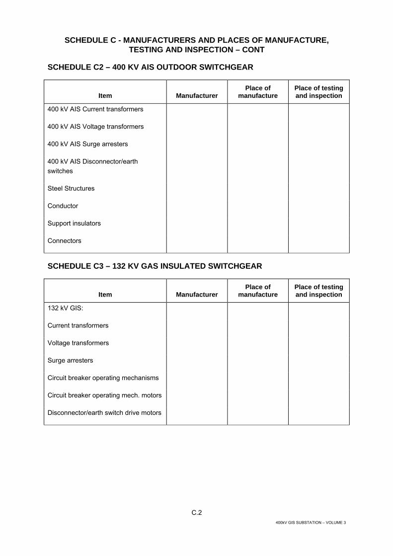
SCHEDULE C2 – 400 KV AIS OUTDOOR SWITCHGEAR
Item
Manufacturer
Place of manufacture
Place of testingand inspection
400 kV AIS Current transformers
400 kV AIS Voltage transformers
400 kV AIS Surge arresters
400 kV AIS Disconnector/earth switches
Steel Structures
Conductor
Support insulators
Connectors
SCHEDULE C3 – 132 KV GAS INSULATED SWITCHGEAR
Item
Manufacturer
Place of manufacture
Place of testingand inspection
132 kV GIS:
Current transformers
Voltage transformers
Surge arresters
Circuit breaker operating mechanisms
Circuit breaker operating mech. motors
Disconnector/earth switch drive motors

C.3 400kV GIS SUBSTATION – VOLUME 3
SCHEDULE C - MANUFACTURERS AND PLACES OF MANUFACTURE, TESTING AND INSPECTION – CONT
SCHEDULE C3 – 132 KV GAS INSULATED SWITCHGEAR - Cont
Item
Manufacturer
Place of manufacture
Place of testingand inspection
SF6 Gas handling plant
SF6 Gas
Partial discharge capacitive couplers
Local control cubicles
GIS Switchroom Crane
Any deviation from this Schedule shall be notified as soon as possible for the Engineer's approval.
SCHEDULE C4 – 132 KV AIS OUTDOOR SWITCHGEAR
Item
Manufacturer
Place of manufacture
Place of testingand inspection
132 kV AIS Current transformers
132 kV AIS Voltage transformers
132 kV AIS Surge arresters
132 kV AIS Disconnector/earth switches
Steel Structures
Conductor
Support insulators
Connectors
C.4 400kV GIS SUBSTATION – VOLUME 3
SCHEDULE C - MANUFACTURERS AND PLACES OF MANUFACTURE, TESTING AND INSPECTION – CONT
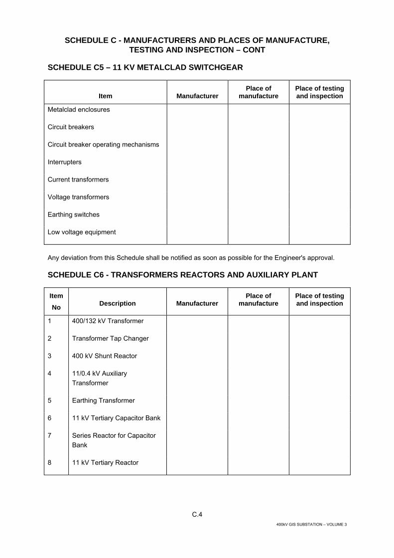
SCHEDULE C5 – 11 KV METALCLAD SWITCHGEAR
Item
Manufacturer
Place of manufacture
Place of testingand inspection
Metalclad enclosures
Circuit breakers
Circuit breaker operating mechanisms
Interrupters
Current transformers
Voltage transformers
Earthing switches
Low voltage equipment
Any deviation from this Schedule shall be notified as soon as possible for the Engineer's approval.
SCHEDULE C6 - TRANSFORMERS REACTORS AND AUXILIARY PLANT
Item
No
Description
Manufacturer
Place of manufacture
Place of testing and inspection
1 400/132 kV Transformer
2 Transformer Tap Changer
3 400 kV Shunt Reactor
4 11/0.4 kV Auxiliary Transformer
5 Earthing Transformer
6 11 kV Tertiary Capacitor Bank
7 Series Reactor for Capacitor Bank
8 11 kV Tertiary Reactor
C.5 400kV GIS SUBSTATION – VOLUME 3
SCHEDULE C - MANUFACTURERS AND PLACES OF MANUFACTURE, TESTING AND INSPECTION – CONT
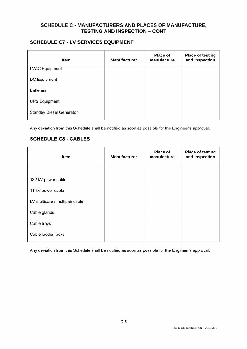
SCHEDULE C7 - LV SERVICES EQUIPMENT
Item
Manufacturer
Place of manufacture
Place of testingand inspection
LVAC Equipment
DC Equipment
Batteries
UPS Equipment
Standby Diesel Generator
Any deviation from this Schedule shall be notified as soon as possible for the Engineer's approval.
SCHEDULE C8 - CABLES
Item
Manufacturer
Place of manufacture
Place of testingand inspection
132 kV power cable
11 kV power cable
LV multicore / multipair cable
Cable glands
Cable trays
Cable ladder racks
Any deviation from this Schedule shall be notified as soon as possible for the Engineer's approval.

C.6 400kV GIS SUBSTATION – VOLUME 3
SCHEDULE C - MANUFACTURERS AND PLACES OF MANUFACTURE, TESTING AND INSPECTION – CONT
SCHEDULE C9 - SUBSTATION CONTROL AND PROTECTION SYSTEMS`
Item
Manufacturer
Place of manufacture
Place of testingand inspection
SCS Substation Computer
SCS Operator Workstations / HMI
Operator Desk and Chair
SCS Colour Visual Display Units
SCS Substation LAN
SCS Printers
SCS Bay Control Unit BCU
SCS I/O Cards for BCU
SCS Software Engineering
SCS Database Engineering
Protection Relays
Any deviation from this Schedule shall be notified as soon as possible for the Engineer's approval.

400kV GIS SUBSTATION – VOLUME 3
SCHEDULE D
TECHNICAL PARTICULARS

D1.1 400kV GIS SUBSTATION – VOLUME 3
SCHEDULE D – TECHNICAL PARTICULARS
SCHEDULE D1 – 400 KV GAS INSULATED SWITCHGEAR
Unit Data Required Offered 1 GENERAL
1.1 Manufacturer & Place of manufacturing
1.2 Type designation
GIS
1.3 Type
Metal enclosed, gas insulated GIS- indoor
1.4 Standards
IEC IEC 62271 - 203, 60694, 60270, 60376, 60480
1.5 Rated voltage
kV 420
1.6 System Voltage
kV 400
1.7 Rated frequency
Hz 50
1.8 Rated lightning impulse withstand voltage
- Phase to earth KVp 1425 - Across the isolating distance kVp 1665 1.9 Rated power frequency withstand voltage
- Phase to earth kV 650 - Across the isolating distance kV 815 - Phase to earth at SF6 pressure of 1 bar kV 1.1 U phase 1.10 Rated short-time withstand current (1 s)
kA 40
1.11 Rated peak withstand current
kA 100
1.12 Type of busbars
Breaker and Half
1.13 Type of enclosure
Single phase enclosures
1.14 Material of enclosure for:
- Circuit breaker Al/St - Busbars Al/St - Other compartments Al/St 1.15 Material of HV conductor
Al/Cu
1.16 Material of contacts (indicate bi-metallic where used)
1.17 Type of contact
Tulip

D1.2 400kV GIS SUBSTATION – VOLUME 3
SCHEDULE D – TECHNICAL PARTICULARS – CONT
SCHEDULE D1 – 400 KV GAS INSULATED SWITCHGEAR - Cont
Unit Data Required Offered 1.18 Minimum subdivision of switchgear:
- Busbars Yes - Busbar disconnect Yes - Circuit breaker Yes - Circuit disconnect Yes - Cable box Yes - Voltage transformer Yes 1.19 Method of compensation of expansion and
contraction
- For busbars - For enclosure 1.20 Type of pressure relief device
Bursting disk
1.21 Rupturing pressure
bar
1.22 Type of filter employed for moisture absorption
Molecular Sieve
1.23 Design lifetime of moisture absorbent
Years 10
1.24 Total mass of switchgear (average per bay)
kg
1.25 Mass of heaviest single component to be handled during erection
kg
1.26 Total mass of SF6 gas (average per bay)
kg
1.27 Density of gas in:
- Circuit breaker compartment (g/l) - Other than circuit breaker compartments (g/l) 1.28 Nominal working gas pressure at 15oC in:
- Circuit breaker compartment bar - Other than circuit breaker compartment bar 1.29 Nominal working gas pressure at 50oC in:
- Circuit breaker compartment bar - Other than circuit breaker compartment bar 1.30 Design maximum pressure for:
- Circuit breaker compartment bar - Other than circuit breaker compartment bar 1.31 Maximum leakage rate for any gas compartment
per
annum Less than 1%

D1.3 400kV GIS SUBSTATION – VOLUME 3
SCHEDULE D – TECHNICAL PARTICULARS – CONT
SCHEDULE D1 – 400 KV GAS INSULATED SWITCHGEAR - Cont
Unit Data Required Offered 1.32 Maximum leakage rate for the whole switchgear
per
annum Less than 1%
1.33 Minimum operating period without total replacement of SF6 gas
years 10
1.34 Minimum thickness of enclosure
mm
1.35 Minimum enclosure puncturing time due to internal arc fault at short-time withstand current
ms Greater than 500
1.36 Minimum factors of safety for switchgear
- Busbars or other connections based on elastic limit
2.5
- Complete insulators based on electro-mechanical test
2.5
- Insulator metal fittings based on elastic limit 2.5 - Steel structures based on elastic limit of
tension members and on crippling loads of compression members
2.5
- Foundations for structures against overturning or uprooting under maximum simultaneous working loadings
2.5
1.37 Seismic factor
UBC Zone 3
2 CIRCUIT BREAKER
2.1 Manufacturer & Place of manufacturing
2.2 Type designation
2.3 Type
Single pressure puffer, SF6
2.4 Standards
IEC 62271 - 203, IEC 62271-100, 61233, 60694, 60427, 60376,
60480
2.5 Rated voltage kV 420
2.6 Rated Current at 50 0C
(Contractor to confirm by calculation) - Main busbar
A
4000
- Bay busbar A 2000 - Line transformer Circuit
A 1600

D1.4 400kV GIS SUBSTATION – VOLUME 3
SCHEDULE D – TECHNICAL PARTICULARS – CONT
SCHEDULE D1 – 400 KV GAS INSULATED SWITCHGEAR - Cont
Unit Data Required Offered 2.7 Rated frequency
Hz 50
2.8 Rated lightning impulse withstand voltage
- Phase to earth kVp 1425 - Across the isolating distance kVp 1665 2.9 Rated power frequency withstand voltage
- Phase to earth kV 650 - Across the isolating distance kV 815 2.10 Rated short-time withstand current (1 s)
kA 40
2.11 Rated peak withstand current
kAp 100
2.12 Rated operating sequence
O -0.3 sec- CO -3 min - CO
2.13 Auto reclosing
O -0.3 sec- CO -3 min - CO
2.14 Rated making current
kAp 100
2.16 Rated breaking current (asymmetrical)
kA To IEC 62271-100
- %dc
%dc
2.17 Rated breaking current under out-of-phase conditions
kA
2.18 First phase to clear factor
1.3
2.18a Transient Recovery Voltages
TRVs To IEC 62271-100
Rated capacitive breaking current To IEC 62271-
100
Rated line charging breaking current A Rated cable charging breaking current A
2.19
Rated Single/Back to Back Capacitor bank breaking current
A

D1.5 400kV GIS SUBSTATION – VOLUME 3
SCHEDULE D – TECHNICAL PARTICULARS – CONT
SCHEDULE D1 – 400 KV GAS INSULATED SWITCHGEAR - Cont
Unit Data Required Offered 2.20 Rated small inductive/reactor breaking currents of:
To IEC 62771-
110
- small inductive A - reactor A 2.21 Maximum overvoltage factor on any switching duty
pu 2.5
2.22 Maximum overvoltage factor when interrupting rated line/cable/capacitor bank charging currents
pu 2.5
2.23 Maximum overvoltage factor when switching small inductive/reactor currents
pu 2.5
2.24 Maximum total break time (trip initiation to final arc extinction)
ms 60
2.25 Opening time (trip initiation to contact separation)
- Without current ms - With 100% rated breaking current
ms
2.26 Maximum time interval between opening of first and last phase of three phase circuit breakers
ms 3
2.27 Maximum time interval between opening of interrupters of one phase
ms
2.28 Closing time from energisation of close coil to latching of circuit breaker in fully closed position
ms
2.29 Making time (energisation of close coil to contact touch)
- Without current ms - 100% making current ms 2.30 Maximum time interval between closure of first
and last phase of three phase circuit breaker
ms 3
2.31 Maximum time interval between closure of interrupters of one phase
ms
2.32 Minimum time from extinction of main arc to contact make during auto-reclosing duty
ms
2.33 Mechanical life of circuit breaker and mechanism in No. of operations
10,000

D1.6 400kV GIS SUBSTATION – VOLUME 3
SCHEDULE D – TECHNICAL PARTICULARS – CONT
SCHEDULE D1 – 400 KV GAS INSULATED SWITCHGEAR - Cont
Unit Data Required Offered 2.34 Electrical contact life in number of operations at:
- Rated current - 2000 A - Fault current - 40 kA 15 to 20 - Cumulative ampere rating 2.35 Number of current interrupting break units in
series per phase
two
2.36 Type of operating mechanism
Spring-charged or hydraulic
2.37 Type of power device (motor charged)
- For closing Spring or hydraulic
- For opening
Spring or hydraulic
2.38 Hand operating facility
yes
2.39 Hand charging facility
yes
2.40 Manual spring release
yes
2.41 Mechanical on/off indicator
yes
2.42 Mechanical spring charge / discharge indication
yes
2.43 Charging time
s
2.44 Number of trip coils
2
2.45 Number of close coils
1
2.46 Nominal control and operating voltage
V 110 DC
2.47 Nominal heater voltage
V 220 AC
2.48 Rated power of trip coil
W
2.49 Rated power of close coil
W
2.50 Rated motor power
W
2.51 Total load of heaters for circuit breaker
W
2.52 Mass of circuit breaker complete (three pole)
kg
2.53 Mass of single phase circuit breaker
- - -
2.54 Emergency Trip Facility during failure of DC supply
yes
D1.7 400kV GIS SUBSTATION – VOLUME 3
SCHEDULE D – TECHNICAL PARTICULARS – CONT
SCHEDULE D1 – 400 KV GAS INSULATED SWITCHGEAR - Cont
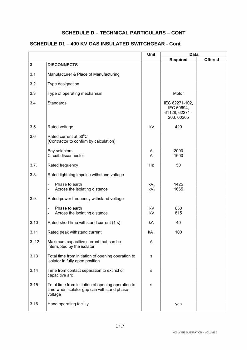
Unit Data Required Offered 3 DISCONNECTS
3.1 Manufacturer & Place of Manufacturing
3.2 Type designation
3.3 Type of operating mechanism
Motor
3.4 Standards
IEC 62271-102, IEC 60694,
61128, 62271 - 203, 60265
3.5 Rated voltage
kV 420
Rated current at 50oC (Contractor to confirm by calculation)
Bay selectors A 2000
3.6
Circuit disconnector A 1600
3.7. Rated frequency
Hz 50
3.8. Rated lightning impulse withstand voltage
- Phase to earth kVp 1425 - Across the isolating distance kVp 1665 3.9. Rated power frequency withstand voltage
- Phase to earth kV 650 - Across the isolating distance kV 815 3.10 Rated short time withstand current (1 s)
kA 40
3.11 Rated peak withstand current
kAp 100
3 .12 Maximum capacitive current that can be interrupted by the isolator
A
3.13 Total time from initiation of opening operation to isolator in fully open position
s
3.14 Time from contact separation to extinct of capacitive arc
s
3.15 Total time from initiation of opening operation to time when isolator gap can withstand phase voltage
s
3.16 Hand operating facility yes
D1.8 400kV GIS SUBSTATION – VOLUME 3
SCHEDULE D – TECHNICAL PARTICULARS – CONT
SCHEDULE D1 – 400 KV GAS INSULATED SWITCHGEAR - Cont
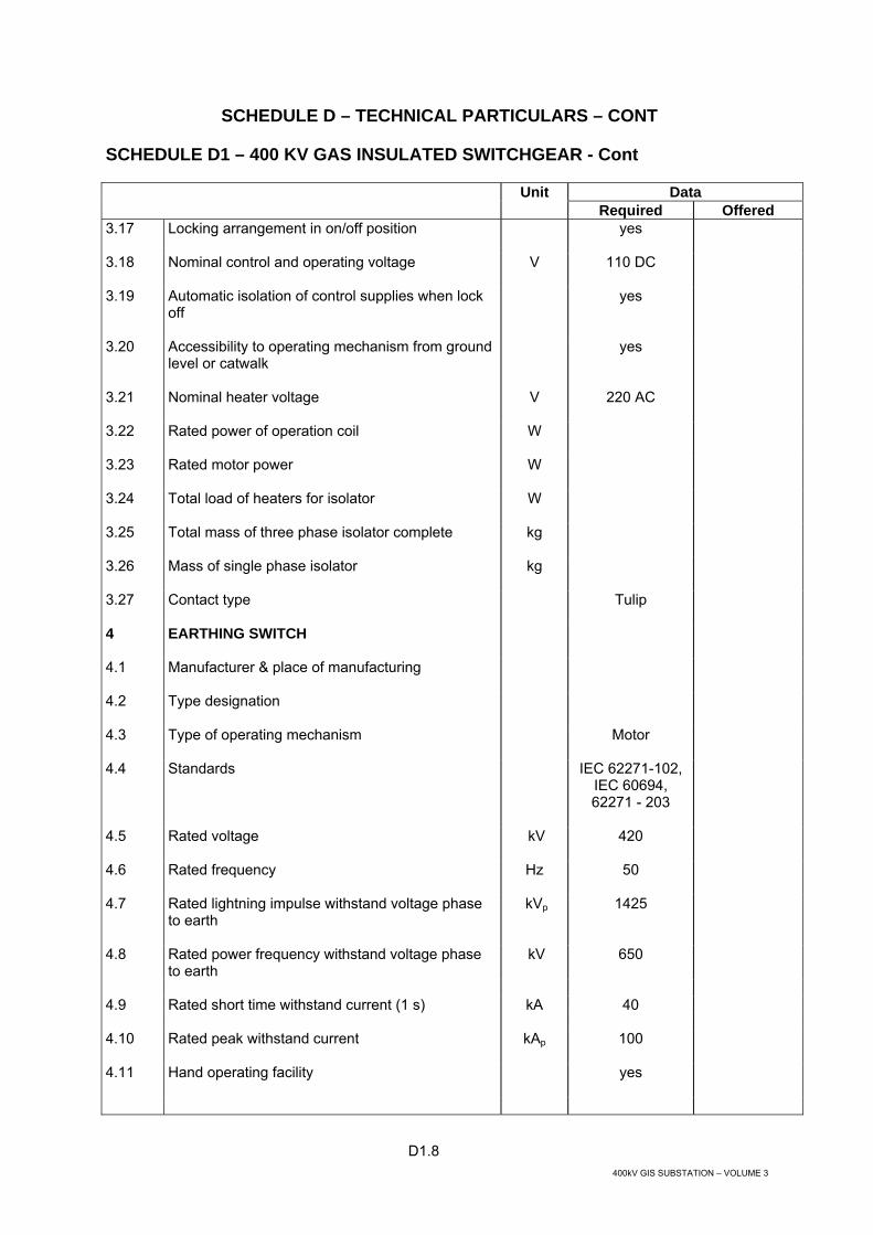
Unit Data Required Offered 3.17 Locking arrangement in on/off position
yes
3.18 Nominal control and operating voltage
V 110 DC
3.19 Automatic isolation of control supplies when lock off
yes
3.20 Accessibility to operating mechanism from ground level or catwalk
yes
3.21 Nominal heater voltage
V 220 AC
3.22 Rated power of operation coil
W
3.23 Rated motor power
W
3.24 Total load of heaters for isolator
W
3.25 Total mass of three phase isolator complete
kg
3.26 Mass of single phase isolator
kg
3.27 Contact type
Tulip
4 EARTHING SWITCH
4.1 Manufacturer & place of manufacturing
4.2 Type designation
4.3 Type of operating mechanism
Motor
4.4 Standards
IEC 62271-102, IEC 60694, 62271 - 203
4.5 Rated voltage
kV 420
4.6 Rated frequency
Hz 50
4.7 Rated lightning impulse withstand voltage phase to earth
kVp 1425
4.8 Rated power frequency withstand voltage phase to earth
kV 650
4.9 Rated short time withstand current (1 s) kA 40 4.10 Rated peak withstand current
kAp 100
4.11 Hand operating facility
yes

D1.9 400kV GIS SUBSTATION – VOLUME 3
SCHEDULE D – TECHNICAL PARTICULARS – CONT
SCHEDULE D1 – 400 KV GAS INSULATED SWITCHGEAR - Cont
Unit Data Required Offered 4.12 Locking arrangement in on/off position
yes
4.13 Nominal control and operating voltage
V 110 DC
4.14 Automatic isolation of control supplies when lock off
yes
4.15 Accessibility to operating mechanism from ground level or catwalk
yes
4.16 Nominal heater voltage
V 220 AC
4.17 Rated power of operating coil
W
4.18 Rated motor power
W
4.19 Total load of heaters for earthing switch
W
4.20 Total mass of earthing switch complete
kg
5 HIGH SPEED EARTHING SWITCH
5.1 Manufacturer & place of manufacturing
5.2 Type designation
5.3 Type of operating mechanism
Motor-spring
5.4 Standards
IEC 62271-102, IEC 60694,
61129, 62271 - 203
5.5 Rated voltage
kV 420
5.6 Rated frequency
Hz 50
5.7 Rated lightning impulse withstand voltage phase to earth
kVp 1425
5.8 Rated power frequency withstand voltage phase to earth
kV 650
5.9 Rated short time withstand current (1 s)
kA 40
5.10 Rated peak withstand current
kAp 100
5.11 Rated short-circuit making current
kAp 100
5.12 Rated capacitive symmetrical breaking current
A
5.13 Rated inductive symmetrical breaking current A

D1.10 400kV GIS SUBSTATION – VOLUME 3
SCHEDULE D – TECHNICAL PARTICULARS – CONT
SCHEDULE D1 – 400 KV GAS INSULATED SWITCHGEAR - Cont
Unit Data Required Offered 5.14 Total time from initiation of opening operation to
earth switch in fully open position
ms
5.15 Time from contact separation to extinction of arc when interrupting rated breaking current
ms
5.16 Making time
ms
5.17 Charging time
s
5.18 Hand operating facility
yes
5.19 Locking arrangement in on/off position
yes
5.20 Nominal control and operating voltage
V d.c. 110
5.21 Automatic isolation of control supplies when lock off
yes
5.22 Accessibility to operating mechanism from ground level or catwalk
yes
5.23 Nominal heater voltage
V 220 AC
5.24 Rated power of operation coil
W
5.25 Rated motor power
W
5.26 Total load of heaters for earthing switch
W
5.27 Total mass of earthing switch complete
kg
6 CURRENT TRANSFORMER
6.1 Manufacturer & place of manufacturing
6.2 Type
Toroidal, GIS enclosed or
external
6.3 Standards
IEC 60694, 60044-1
6.4 Rated voltage GIS kV 420 Cores V 6.5 Rated lightning impulse withstand voltage phase
to earth
GIS kVp 1425 Cores kVp

D1.11 400kV GIS SUBSTATION – VOLUME 3
SCHEDULE D – TECHNICAL PARTICULARS – CONT
SCHEDULE D1 – 400 KV GAS INSULATED SWITCHGEAR - Cont
Unit Data Required Offered 6.6 Rated power frequency withstand voltage phase
to earth
GIS kV 650 Cores kV 3 kV (EK < 2 kV) kV 5 kV (EK ≥ 2 kV) 6.7 Rated power frequency voltage between
secondaries
kV 3
6.8 Inter-turn test M/P type kVp 4.5 Class PX To IEC 60044-1 6.9 Rated frequency
Hz 50
6.10 Rated continuous thermal current at 50oC
A
6.11 Rated short-time withstand current (1 s)
kA 40
6.12 Rated dynamic current
kAp 100
6.13 Are earthed metal screens fitted between primary and secondary windings
6.14 Is current transformer housed in a separate gas compartment
6.15 Details of all current transformers are to be provided by the Contractor post contract award
- Number of cores - Rated extended primary current - Ratio (TR = turns ratio)
• I core A • II core A • III core A • IV core
A
- Class
7 VOLTAGE TRANSFORMERS
7.1 Manufacturer & Place of manufacturing
7.2 Type designation for
- Line transformer – 3 phase
- Busbar transformer – 3 phase

D1.12 400kV GIS SUBSTATION – VOLUME 3
SCHEDULE D – TECHNICAL PARTICULARS – CONT
SCHEDULE D1 – 400 KV GAS INSULATED SWITCHGEAR - Cont
Unit Data Required Offered 7.3 Type
Inductive, SF6
gas insulated, enclosed
7.4 Standards
IEC 60186,60694, 62271 - 203,
60044-2
7.5 Rated voltage
kV 420
7.6 Rated frequency
Hz 50
7.7 Rated lightning impulse phase to earth
KVp 1425
7.8 Rated power frequency withstand voltage phase to earth
kV 650
7.9 Maximum permissible partial discharge level Um
pC 10
7.10 Maximum permissible partial discharge level 1.2Um /√3
pC 5
7.11 Maximum capacitive current discharge rating
A
7.12 Method of suppressing ferroresonance phenomena
7.13 Line bay voltage transformer
- Number of secondaries - Rated transformation ratio kV - Rated accuracy class
• I secondary • II secondary
- Rated output
• I secondary VA • II secondary
VA
- Mass of single/three phase voltage transformer
kg
7.14 Busbar voltage transformer
- Number of secondaries - Rated transformation ratio kV - Rated accuracy class
• I secondary

D1.13 400kV GIS SUBSTATION – VOLUME 3
SCHEDULE D – TECHNICAL PARTICULARS – CONT
SCHEDULE D1 – 400 KV GAS INSULATED SWITCHGEAR - Cont
Unit Data Required Offered - Rated output (Burden to be 25-100% rated
burden)
VA
• I secondary
- Mass of single/three phase voltage transformer
kg
8 SURGE ARRESTERS
8.1 Type
8.2
Standard IEC 60099-4, 60099-1 60099-5,
60694
8.3 Rated/system voltage
kV
420/400
- Maximum overvoltage factor on the system due to any switching duty
pu 2.5
8.4 Rated system frequency
Hz 50
8.5 Condition of system neutral
Solid
8.6 Nominal Discharge current
kA crest
8.7 Energy capability as per IEC 60099-4 kJ/ kV
8.8 Rated voltage - MOA
kV
8.9 Long duration discharge class as per IEC 60099-4
Class 3
8.10 Maximum Continuous Operating Voltage (COV)
kV
8.11 TOV capability for
- 1 sec kV - 10 sec kV 8.12 Maximum residual voltage with current wave
- Switching Surges - 1kA / 2kA kV - 8/20 μs - 5kA kV - 8/20 μs - 10kA kV
8.14 Discharge current withstand strength
- High current (4/10 μs) kAp - Low current 2000A Ap

D1.14 400kV GIS SUBSTATION – VOLUME 3
SCHEDULE D – TECHNICAL PARTICULARS – CONT
SCHEDULE D1 – 400 KV GAS INSULATED SWITCHGEAR - Cont
Unit Data Required Offered 8.15 Pressure relief capability
- High current (0.2 s) kA - Low current
8.16 Rating of earth connections
kA/sec 40/1
8.17 Surge counter provided
Yes
9 CABLE BOX (WHEN APPLICABLE).
9.1 Manufacturer & Place of manufacturing
9.2 Type of designation
9.3 Standards
IEC 60859
9.4 Cable HV test withstand capability
kV
9.5 Rated normal current at 40oC
A
9.6 Required current at 50oC (Contractor to confirm by calculation)
A
9.7 Rated short time withstand current (1s)
kA 40
9.8 Rated peak withstand current
kA 100
9.9 Total mass of three phase cable box complete
kg
10 MANUFACTURER QUALITY SYSTEM IN ACCORDANCE TO ISO 9000, 9001, 9002, 9003 AND 9004
Yes
10.1 Date of issue
Latest
10.2 Validity
Valid Certificates –Yes
11 TYPE TEST CERTIFICATE TO BE ISSUED BY INDEPENDENT LABORATORY OR INDEPENDENTLY WITNESSED TYPE TEST CERTIFICATE TO BE SUBMITTED
Yes

D2.1 400kV GIS SUBSTATION – VOLUME 3
SCHEDULE D – TECHNICAL PARTICULARS – CONT
SCHEDULE D2 – 400 KV OPEN TERMINAL SWITCHGEAR
Unit Data Required Offered 1 GENERAL
1.1 Standards
IEC IEC 62271-100, 62271-102, 60694,
60233, 60044, 60186, 60383,
60815
1.2 Rated voltage
kV 420
1.3 System Voltage
kV 400
1.4 Rated frequency
Hz 50
1.5 Rated lightning impulse withstand voltage
Phase to earth kVp 1425 Across the isolating distance kVp 1665 1.6 Rated power frequency withstand voltage Phase to earth kV 520 Across the isolating distance kV 610 1.7 Rated short-time withstand current (1 s)
kA 40
1.8 Rated peak withstand current
kA 100
1.9 Rated Current – Cable Feeder at 50 oC (Contractor to confirm by calculation) A 1.10 Material of HV conductor
Aluminium
1.11 Material of contacts
Bi-metallic
1.12 Minimum factors of safety for switchgear
Busbars or other connections based on elastic limit
2.5
Complete insulators based on electro-mechanical test
2.5
Insulator metal fittings based on elastic limit
2.5
Steel structures based on elastic limit of tension members and on crippling loads of compression members
2.5
Foundations for structures against overturning or uprooting under maximum simultaneous working loadings
2.5

D2.2 400kV GIS SUBSTATION – VOLUME 3
SCHEDULE D – TECHNICAL PARTICULARS – CONT
SCHEDULE D2 – 400 KV OPEN TERMINAL SWITCHGEAR - Cont
Unit Data Required Offered 1.13 Creepage distance (based on Um)
mm/kV 31
1.14 Seismic factor
As UBC
2 ISOLATORS
2.1 Type designation
2.2 Type of operating mechanism
Motor
2.3 Standards
IEC 62271-102, IEC 60694, 61128,
60265
2.4 Maximum capacitive current that can be interrupted by the isolator
A
2.5 Total time from initiation of opening operation to isolator in fully open position
s
2.6 Time from contact separation to extinct of capacitive arc
s
2.7 Total time from initiation of opening operation to time when isolator gap can withstand phase voltage
s
2.8 Hand operating facility
Yes
2.9 Locking arrangement in on/off position
Yes
2.10 Nominal control and operating voltage
V 110 DC
2.11 Automatic isolation of control supplies when lock off
Yes
2.12 Accessibility to operating mechanism from ground level
Yes
2.13 Nominal heater voltage
V 220 AC
2.14 Rated power of operation coil
W
2.15 Rated motor power
W
2.16 Total load of heaters for isolator
W
2.17 Total mass of three phase isolator complete
kg
2.18 Mass of single phase isolator
kg
2.19 Contact type
2.20 Type of interlocking

D2.3 400kV GIS SUBSTATION – VOLUME 3
SCHEDULE D – TECHNICAL PARTICULARS – CONT
SCHEDULE D2 – 400 KV OPEN TERMINAL SWITCHGEAR - Cont
Unit Data Required Offered 3 EARTHING SWITCH
3.1 Type designation
3.2 Type of operating mechanism
Hand
3.3 Standards
IEC 62271-102, 60694
3.4 Hand operating facility
Yes
3.5 Locking arrangement in on/off position
Yes
3.6 Nominal control and operating voltage
V 110 DC
3.7 Automatic isolation of control supplies when lock off
Yes
3.8 Accessibility to operating mechanism from ground level
Yes
3.9 Nominal heater voltage
V 220 AC
3.10 Total load of heaters for earthing switch
W
3.11 Total mass of earthing switch complete
kg

D2.4 400kV GIS SUBSTATION – VOLUME 3
SCHEDULE D – TECHNICAL PARTICULARS – CONT
SCHEDULE D2 – 400 KV OPEN TERMINAL SWITCHGEAR - Cont
Unit Data Required Offered 4 CURRENT TRANSFORMER
4.1 Type
Post
4.2 Standards
IEC 60694, 60044-1
4.3 Rated continuous thermal current at 50oC
Rated extended primary current
Note: All Cl PX CTs shall be ISN 1.2 A
4.4 Cable feeder bays current transformer
To suit specific requirements
Number of cores
Rated extended primary current
Ratio (TR – turns ratio)
I core A II core A III core A IV core
A
Class
I core II core III core IV core
Knee point voltage (Ek)
I core V II core V III core V IV core
V
Exciting current (IE) at Ek
I core mA II core mA III core mA IV core
mA
Rated output (burden to be 25-100% rated burden)
I core VA II core VA III core VA IV core
VA

D2.5 400kV GIS SUBSTATION – VOLUME 3
SCHEDULE D – TECHNICAL PARTICULARS – CONT
SCHEDULE D2 – 400 KV OPEN TERMINAL SWITCHGEAR - Cont
Unit Data Required Offered Total mass of single phase current
transformer complete
kg
4.5 Bus coupler and bus section bays current transformer
To suit specific arrangement
Number of cores
120%
5 CAPACITIVE VOLTAGE TRANSFORMERS
5.1 Type
Capacitive
5.2 Standards IEC 60186, IEC/PAS 60044-
5:2002
5.3 Maximum permissible partial discharge level Um
pC 10
5.4 Maximum permissible partial discharge level 1.2Um /√3
pC 5
5.5 Method of suppressing ferroresonance phenomena
5.5 Line voltage transformer
5.7 Number of secondaries
2
Rated transformation ratio kV 132/√3 / 0.11/√3 /0.11/√3
Rated accuracy class
I secondary 3P/1.0 II secondary
3P
Rated output (burden to be 25-100% rated burden)
I secondary VA II secondary
VA
Mass of single phase voltage transformer
kg

D2.6 400kV GIS SUBSTATION – VOLUME 3
SCHEDULE D – TECHNICAL PARTICULARS – CONT
SCHEDULE D2 – 400 KV OPEN TERMINAL SWITCHGEAR - Cont
Unit Data Required Offered 6 SURGE ARRESTERS
6.1 Type
6.2 Standard IEC 60099-4, 60099-1 60099-5,
60694
6.3 Rated/system voltage
kV
145/132
6.4 Maximum overvoltage factor on the system due to any switching duty
pu 2.5
6.5 Rated system frequency
Hz 50
6.6 Condition of system neutral
Solid
6.7 Nominal Discharge current
kA crest
6.8 Energy capability as per IEC 60099-4 kJ/ kV
6.9 Rated voltage - MOA
kV
6.10 Long duration discharge class as per IEC 60099-4
Class
6.11 Maximum Continuous Operating Voltage (COV)
kV
6.12 TOV capability for
1 sec kV 10 sec
kV
6.14 Switching Surges - 1kA / 2kA kV 8/20 μs - 5kA kV 8/20 μs - 10kA kV 6.15 Discharge current withstand strength kAp High current (4/10 μs) Ap Low current 2000A
6.16 Pressure relief capability kA High current (0.2 s) Low current
kA/sec As per IEC
6.17 Rating of earth connections
40/1
6.18 Surge counter provided
Yes

D2.7 400kV GIS SUBSTATION – VOLUME 3
SCHEDULE D – TECHNICAL PARTICULARS – CONT
SCHEDULE D2 – 400 KV OPEN TERMINAL SWITCHGEAR - Cont
Unit Data Required Offered 7 BUSBARS AND CONNECTIONS
7.1 Type (flexible or tubular)
7.2 Material
7.3 Short-circuit current rating / duration
kA/s
7.4 Normal current rating at 40oC at 50oC
A A
7.5 Maximum continuous current rating
A
7.6 Flexible conductors stranding nominal cross-sectional area outer diameter no. of conductors per bundle spacing between conductors
mm2
mm
mm
7.7 Tubular conductors nominal cross-sectional area outer diameter inner diameter
mm2
mm
mm
7.8 Maximum stress at surface of flexible conductor
kV/mm
7.9 Radio influence voltage level measured at 1.1 times Us/√3 at 1 MHz
µV

D2.8 400kV GIS SUBSTATION – VOLUME 3
SCHEDULE D – TECHNICAL PARTICULARS – CONT
SCHEDULE D2 – 400 KV OPEN TERMINAL SWITCHGEAR - Cont
Unit Data Required Offered 8 POST TYPE INSULATORS
8.1 Type designation
8.2 Insulator material
8.3 Number of units in complete post insulator
8.4 Length of each unit
mm
8.5 Mass of complete post insulator
kg
8.6 Maximum cantilever working load (complete post insulator)
N
8.7 Minimum cantilever breaking load, upright (complete post insulator)
N
8.8 Power frequency withstand voltage dry: wet
kV
8.9 Basic insulation level
kVp
8.10 Minimum dry/wet switching surge withstand level
kVp
8.11 Radio influence voltage level measured at 1.1 times Us/√3 at 1 MHz
µv

D2.9 400kV GIS SUBSTATION – VOLUME 3
SCHEDULE D – TECHNICAL PARTICULARS – CONT
SCHEDULE D2 – 400 KV OPEN TERMINAL SWITCHGEAR - Cont
Unit Data Required Offered 9 TENSION AND SUSPENSION
INSULATORS
9.1 Type designation
9.2 Insulator material
9.3 Number of units in string
mm
9.4 Greatest diameter of units
mm
9.5 Distance between centres of units
mm
9.6 Length of string, overall
mm
9.7 Mass of string complete with all fittings
kg
9.8 Maximum working load
N
9.9 Power frequency withstand voltage of complete string
kV
9.10 Basic insulation level of complete string
kVp
9.11 Minimum wet switching surge withstand level of complete string
kVp
9.12 Radio influence voltage measured at 1.1 times Us/√3 at 1 MHz
µv

D2.10 400kV GIS SUBSTATION – VOLUME 3
SCHEDULE D – TECHNICAL PARTICULARS – CONT
SCHEDULE D2 – 400 KV OPEN TERMINAL SWITCHGEAR – Cont
Unit Data Required Offered 10 400 KV LINE TRAPS
10.1 Maker's type and designation
10.2 Main coil insulation – class
10.3 Rated continuous current
A
10.4 Rated short time current (1 second/3 seconds)
kA
10.5 Power frequency
10.6 Insulating level across line traps at:
10.6.1 Power frequency
10.6.2 Impulse
10.7 Rated voltage level of protective device
kV
10.8 Centre frequency
kHz
10.9 Bank width of blocking range
kHz
10.10 Self resonant frequency
kHz
10.11 Tapping loss
db
10.12 Blocking impedance
Ω
10.13 Total mass
kg

D3.1 400kV GIS SUBSTATION – VOLUME 3
SCHEDULE D – TECHNICAL PARTICULARS – CONT
SCHEDULE D3 – 132 KV GAS INSULATED SWITCHGEAR
Unit Data Required Offered 1 GENERAL
1.1 Manufacturer & Place of manufacturing
1.2 Type designation
GIS
1.3 Type
Metal enclosed, gas insulated GIS-
indoor
1.4 Standards
IEC IEC 62271 - 203, 60694, 60270, 60376, 60480
1.5 Rated voltage
kV 145
1.6 System Voltage
kV 132
1.7 Rated frequency
Hz 50
1.8 Rated lightning impulse withstand voltage
- Phase to earth kVp 650 - Across the isolating distance kVp 750 1.9 Rated power frequency withstand voltage
- Phase to earth kV 275 - Across the isolating distance kV 315 - Phase to earth at SF6 pressure of 1 bar kV 1.1 U phase 1.10 Rated short-time withstand current (1 s)
kA 40
1.11 Rated peak withstand current
kA 80
1.12 Type of busbars
Double
1.13 Type of enclosure
Single/Three phase enclosed
1.14 Material of enclosure for:
- Circuit breaker Al/St - Busbars Al/St - Other compartments Al/St 1.15 Material of HV conductor
Al/Cu
1.16 Material of contacts (indicate bi-metallic where used)

D3.2 400kV GIS SUBSTATION – VOLUME 3
SCHEDULE D – TECHNICAL PARTICULARS - CONT
SCHEDULE D3 – 132 KV GAS INSULATED SWITCHGEAR - Cont
Unit Data Required Offered 1.17 Type of contact Tulip 1.18 Minimum subdivision of switchgear:
- Busbars - Busbar isolator - Circuit breaker Yes - Circuit isolator - Cable box - Voltage transformer Yes 1.19 Method of compensation of expansion and
contraction
- For busbars - For enclosure 1.20 Type of pressure relief device
Bursting disk
1.21 Rupturing pressure
bar
1.22 Type of filter employed for moisture absorption
Molecular Sieve
1.23 Design lifetime of moisture absorbent
Years 10
1.24 Total mass of switchgear (average per bay)
kg
1.25 Mass of heaviest single component to be handled during erection
kg
1.26 Total mass of SF6 gas (average per bay)
kg
1.27 Density of gas in:
- Circuit breaker compartment (g/l) - Other than circuit breaker compartments (g/l) 1.28 Nominal working gas pressure at 15oC in:
- Circuit breaker compartment bar - Other than circuit breaker compartment bar 1.29 Nominal working gas pressure at 50oC in:
- Circuit breaker compartment bar - Other than circuit breaker compartment bar 1.30 Design maximum pressure for:
- Circuit breaker compartment bar - Other than circuit breaker compartment bar

D3.3 400kV GIS SUBSTATION – VOLUME 3
SCHEDULE D – TECHNICAL PARTICULARS - CONT
SCHEDULE D3 – 132 KV GAS INSULATED SWITCHGEAR - Cont
Unit Data Required Offered 1.31 Maximum leakage rate for any gas compartment
per
annum Less than 1%
1.32 Maximum leakage rate for the whole switchgear
per
annum Less than 1%
1.33 Minimum operating period without total replacement of SF6 gas
years 10
1.34 Minimum thickness of enclosure
mm
1.35 Minimum enclosure puncturing time due to internal arc fault at short-time withstand current
ms Greater than 500
1.36 Minimum factors of safety for switchgear
- Busbars or other connections based on elastic limit
2.5
- Complete insulators based on electro-mechanical test
2.5
- Insulator metal fittings based on elastic limit 2.5 - Steel structures based on elastic limit of
tension members and on crippling loads of compression members
2.5
- Foundations for structures against overturning or uprooting under maximum simultaneous working loadings
2.5
1.37 Seismic factor
2 CIRCUIT BREAKER
2.1 Manufacturer & Place of manufacturing
2.2 Type designation
2.3 Type
Single pressure puffer, SF6
2.4 Standards
IEC 62271 - 203, IEC 62271-100, 61233, 60694, 60427, 60376,
60480
2.5 Rated voltage kV 132
2.6a Rated Current – Busbars, Bus Section and Bus Coupler
- at 50 0C (Contractor to confirm by calculation) A 3150

D3.4 400kV GIS SUBSTATION – VOLUME 3
SCHEDULE D – TECHNICAL PARTICULARS - CONT
SCHEDULE D3 – 132 KV GAS INSULATED SWITCHGEAR - Cont
Unit Data Required Offered 2.6b Rated Current – Transformer/Transformer Feeder
- at 50 0C (Contractor to confirm by calculation)
A 1600
2.6c Rated Current – Incoming Feeder
- at 50 0C (Contractor to confirm by calculation)
A 1600
2.7 Rated frequency
Hz 50
2.8 Rated lightning impulse withstand voltage
- Phase to earth kVp 650 - Across the isolating distance kVp 750 2.9 Rated power frequency withstand voltage
- Phase to earth kV 275 - Across the isolating distance kV 315 2.10 Rated short-time withstand current (1 s)
kA 40
2.11 Rated peak withstand current
kAp 80
2.12 Rated operating sequence
O -0.3 sec- CO -3 min - CO
2.13 Auto reclosing
O -0.3 sec- CO -3 min - CO
2.14 Rated making current
kAp 80
2.16 Rated breaking current (asymmetrical)
kA To IEC 62271-100
- %dc
%dc
2.17 Rated breaking current under out-of-phase conditions
kA
2.18 First phase to clear factor
1.3
2.18a Transient Recovery Voltages
TRVs To IEC 62271-100
Rated capacitive breaking current To IEC 62271-100 Rated line charging breaking current A Rated cable charging breaking current A
2.19
Rated Single/Back to Back Capacitor bank breaking current
A

D3.5 400kV GIS SUBSTATION – VOLUME 3
SCHEDULE D – TECHNICAL PARTICULARS - CONT
SCHEDULE D3 – 132 KV GAS INSULATED SWITCHGEAR - Cont
Unit Data Required Offered 2.20 Rated small inductive/reactor breaking currents of:
To IEC 62771-110
- small inductive A - reactor A 2.21 Maximum overvoltage factor on any switching duty
pu 2.5
2.22 Maximum overvoltage factor when interrupting rated line/cable/capacitor bank charging currents
pu 2.5
2.23 Maximum overvoltage factor when switching small inductive/reactor currents
pu 2.5
2.24 Maximum total break time (trip initiation to final arc extinction)
ms 60
2.25 Opening time (trip initiation to contact separation)
- Without current ms - With 100% rated breaking current
ms
2.26 Maximum time interval between opening of first and last phase of three phase circuit breakers
ms 3
2.27 Maximum time interval between opening of interrupters of one phase
- - -
2.28 Closing time from energisation of close coil to latching of circuit breaker in fully closed position
ms
2.29 Making time (energisation of close coil to contact touch)
- Without current ms - 100% making current ms 2.30 Maximum time interval between closure of first
and last phase of three phase circuit breaker
ms 3
2.31 Maximum time interval between closure of interrupters of one phase
- - -
2.32 Minimum time from extinction of main arc to contact make during auto-reclosing duty
ms 300
2.33 Mechanical life of circuit breaker and mechanism in No. of operations
10,000

D3.6 400kV GIS SUBSTATION – VOLUME 3
SCHEDULE D – TECHNICAL PARTICULARS - CONT
SCHEDULE D3 – 132 KV GAS INSULATED SWITCHGEAR - Cont
Unit Data Required Offered 2.34 Electrical contact life in number of operations at:
- Rated current - 3150A/1600A - Fault current - 40 kA 15 to 20 - Cumulative ampere rating 2.35 Number of current interrupting break units in
series per phase
one
2.36 Type of operating mechanism
Spring-charged or hydraulic
2.37 Type of power device (motor changed)
- For closing Spring or hydraulic
- For opening
Spring or hydraulic
2.38 Hand operating facility
yes
2.39 Hand charging facility
yes
2.40 Manual spring release
yes
2.41 Mechanical on/off indicator
yes
2.42 Mechanical spring charge / discharge indication
yes
2.43 Charging time
s
2.44 Number of trip coils
2
2.45 Number of close coils
1
2.46 Nominal control and operating voltage
V 110 DC
2.47 Nominal heater voltage
V 220 AC
2.48 Rated power of trip coil
W
2.49 Rated power of close coil
W
2.50 Rated motor power
W
2.51 Total load of heaters for circuit breaker
W
2.52 Mass of circuit breaker complete (three pole)
kg
2.53 Mass of single phase circuit breaker
- - -
D3.7 400kV GIS SUBSTATION – VOLUME 3
SCHEDULE D – TECHNICAL PARTICULARS - CONT
SCHEDULE D3 – 132 KV GAS INSULATED SWITCHGEAR - Cont
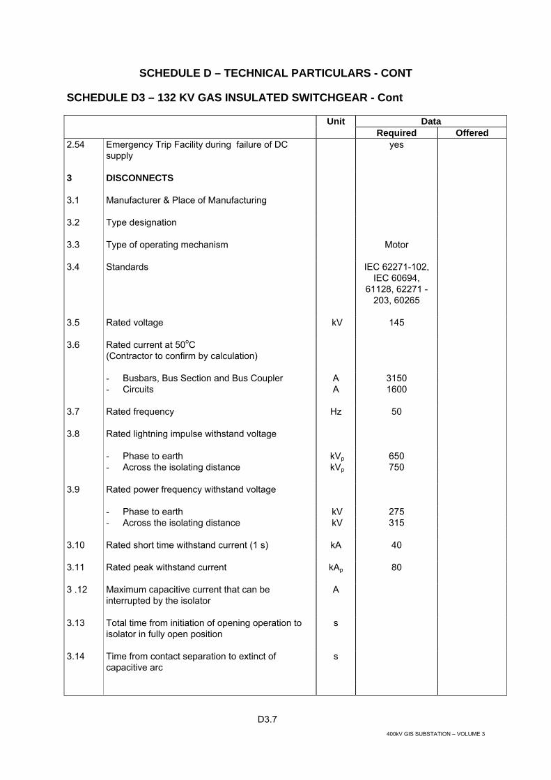
Unit Data Required Offered 2.54 Emergency Trip Facility during failure of DC
supply
yes
3 DISCONNECTS
3.1 Manufacturer & Place of Manufacturing
3.2 Type designation
3.3 Type of operating mechanism
Motor
3.4 Standards
IEC 62271-102, IEC 60694,
61128, 62271 - 203, 60265
3.5 Rated voltage
kV 145
Rated current at 50oC (Contractor to confirm by calculation)
- Busbars, Bus Section and Bus Coupler A 3150
3.6
- Circuits
A 1600
3.7 Rated frequency
Hz 50
3.8 Rated lightning impulse withstand voltage
- Phase to earth kVp 650 - Across the isolating distance kVp 750 3.9 Rated power frequency withstand voltage
- Phase to earth kV 275 - Across the isolating distance kV 315 3.10 Rated short time withstand current (1 s)
kA 40
3.11 Rated peak withstand current
kAp 80
3 .12 Maximum capacitive current that can be interrupted by the isolator
A
3.13 Total time from initiation of opening operation to isolator in fully open position
s
3.14 Time from contact separation to extinct of capacitive arc
s

D3.8 400kV GIS SUBSTATION – VOLUME 3
SCHEDULE D – TECHNICAL PARTICULARS - CONT
SCHEDULE D3 – 132 KV GAS INSULATED SWITCHGEAR - Cont
Unit Data Required Offered 3.15 Total time from initiation of opening operation to
time when isolator gap can withstand phase voltage
s
3.16 Hand operating facility
yes
3.17 Locking arrangement in on/off position
yes
3.18 Nominal control and operating voltage
V 110 DC
3.19 Automatic isolation of control supplies when lock off
yes
3.20 Accessibility to operating mechanism from ground level or catwalk
yes
3.21 Nominal heater voltage
V 220 AC
3.22 Rated power of operation coil
W
3.23 Rated motor power
W
3.24 Total load of heaters for isolator
W
3.25 Total mass of three phase isolator complete
kg
3.26 Mass of single phase isolator
kg
3.27 Contact type
Tulip
4 EARTHING SWITCH
4.1 Manufacturer & place of manufacturing
4.2 Type designation
4.3 Type of operating mechanism
Motor
4.4 Standards
IEC 62271-102, IEC 60694, 62271
- 203
4.5 Rated voltage
kV 145
4.6 Rated frequency
Hz 50
4.7 Rated lightning impulse withstand voltage phase to earth
kVp 650
4.8 Rated power frequency withstand voltage phase to earth
kV 275

D3.9 400kV GIS SUBSTATION – VOLUME 3
SCHEDULE D – TECHNICAL PARTICULARS - CONT
SCHEDULE D3 – 132 KV GAS INSULATED SWITCHGEAR - Cont
Unit Data Required Offered 4.9 Rated short time withstand current (1 s)
kA 40
4.10 Rated peak withstand current
kA 80
4.11 Hand operating facility
yes
4.12 Locking arrangement in on/off position
yes
4.13 Nominal control and operating voltage
V 110 DC
4.14 Automatic isolation of control supplies when lock off
yes
4.15 Accessibility to operating mechanism from ground level or catwalk
yes
4.16 Nominal heater voltage
V 220 AC
4.17 Rated power of operating coil
W
4.18 Rated motor power
W
4.19 Total load of heaters for earthing switch
W
4.20 Total mass of earthing switch complete
kg
5 HIGH SPEED EARTHING SWITCH
5.1 Manufacturer & place of manufacturing
5.2 Type designation
5.3 Type of operating mechanism
Motor-spring
5.4 Standards
IEC 62271-102, IEC 60694,
61129, 62271 - 203
5.5 Rated voltage
kV 145
5.6 Rated frequency
Hz 50
5.7 Rated lightning impulse withstand voltage phase to earth
kVp 650
5.8 Rated power frequency withstand voltage phase to earth
kV 275

D3.10 400kV GIS SUBSTATION – VOLUME 3
SCHEDULE D – TECHNICAL PARTICULARS - CONT
SCHEDULE D3 – 132 KV GAS INSULATED SWITCHGEAR - Cont
Unit Data Required Offered 5.9 Rated short time withstand current (1 s)
kA 40
5.10 Rated peak withstand current
kAp 80
5.11 Rated short-circuit making current
kAp 80
5.12 Rated capacitive symmetrical breaking current
A
5.13 Rated inductive symmetrical breaking current
A
5.14 Total time from initiation of opening operation to earth switch in fully open position
ms
5.15 Time from contact separation to extinction of arc when interrupting rated breaking current
ms
5.16 Making time
ms
5.17 Charging time
s
5.18 Hand operating facility
yes
5.19 Locking arrangement in on/off position
yes
5.20 Nominal control and operating voltage
V d.c. 110
5.21 Automatic isolation of control supplies when lock off
yes
5.22 Accessibility to operating mechanism from ground level or catwalk
yes
5.23 Nominal heater voltage
V 220 AC
5.24 Rated power of operation coil
W
5.25 Rated motor power
W
5.26 Total load of heaters for earthing switch
W
5.27 Total mass of earthing switch complete
kg
6 CURRENT TRANSFORMER
6.1 Manufacturer & place of manufacturing
6.2 Type
Toroidal, GIS enclosed
6.3 Standards IEC 60694, 60044-1
D3.11 400kV GIS SUBSTATION – VOLUME 3
SCHEDULE D – TECHNICAL PARTICULARS - CONT
SCHEDULE D3 – 132 KV GAS INSULATED SWITCHGEAR - Cont
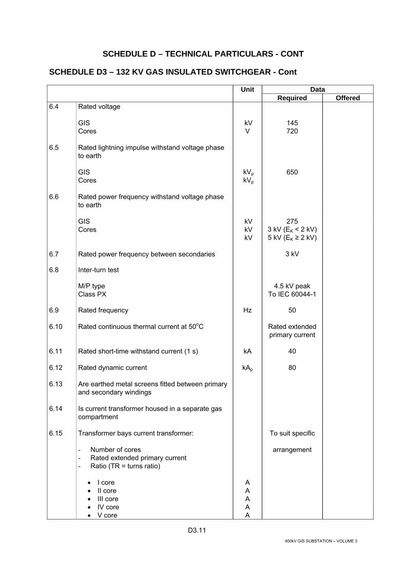
Unit Data Required Offered 6.4 Rated voltage
GIS kV 145 Cores V 720 6.5 Rated lightning impulse withstand voltage phase
to earth
GIS kVp 650 Cores kVp 6.6 Rated power frequency withstand voltage phase
to earth
GIS kV 275 Cores kV 3 kV (EK < 2 kV) kV 5 kV (EK ≥ 2 kV) 6.7 Rated power frequency between secondaries 3 kV
6.8 Inter-turn test
M/P type 4.5 kV peak Class PX
To IEC 60044-1
6.9 Rated frequency
Hz 50
6.10 Rated continuous thermal current at 50oC
Rated extended primary current
6.11 Rated short-time withstand current (1 s)
kA 40
6.12 Rated dynamic current
kAp 80
6.13 Are earthed metal screens fitted between primary and secondary windings
6.14 Is current transformer housed in a separate gas compartment
6.15 Transformer bays current transformer:
To suit specific
- Number of cores arrangement - Rated extended primary current - Ratio (TR = turns ratio)
• I core A • II core A • III core A • IV core A • V core A

D3.12 400kV GIS SUBSTATION – VOLUME 3
SCHEDULE D – TECHNICAL PARTICULARS – CONT
SCHEDULE D3 – 132 KV GAS INSULATED SWITCHGEAR – Cont
Unit Data Required Offered - Class
• I core • II core • III core • IV core • V core
- Knee point voltage (Ek)
• I core V • II core V • III core V • IV core V • V core
V
- Exciting current (IE ) at Ek
• I core mA • II core mA • III core mA • IV core mA • V core
mA
- Rated output (Burden to be 25-100% rated burden)
• I core VA • II core VA • III core VA • IV core VA • V core VA 6.16 Line bays current transformer
To suit specific
- Number of cores arrangement - Rated extended primary current - Ratio (TR = turns ratio) - Knee point voltage (Ek) 6.17 Bus Section & Bus Coupler CT No.1
To suit specific
- Number of cores arrangement - Rated extended primary current - Ratio (TR = turns ratio) 6.18 Bus Section & Bus Coupler CT No. 2 (at the other
side of circuit breaker)
To suit specific
- Number of cores arrangement

D3.13 400kV GIS SUBSTATION – VOLUME 3
SCHEDULE D – TECHNICAL PARTICULARS - CONT
SCHEDULE D3 – 132 KV GAS INSULATED SWITCHGEAR - Cont
Unit Data Required Offered - Rated extended primary current - Ratio (TR = turns ratio) 7 VOLTAGE TRANSFORMERS
7.1 Manufacturer & Place of manufacturing
7.2 Type designation for
- Line transformer – 3 phase - Busbar transformer – 3 phase
7.3 Type
Inductive, SF6 gas insulated, enclosed
7.4 Standards
IEC 60186,60694, 62271 - 203,
60044-2
7.5 Rated voltage
kV 145
7.6 Rated frequency
Hz 50
7.7 Rated lightning impulse phase to earth
kVp 650
7.8 Rated power frequency withstand voltage phase to earth
kV 275
7.9 Maximum permissible partial discharge level Um
pC 10
7.10 Maximum permissible partial discharge level 1.2Um /√3
pC 5
7.11 Maximum capacitive current discharge rating
A TBA
7.12 Method of suppressing ferroresonance phenomena
7.13 Line bay voltage transformer
- Number of secondaries - Rated transformation ratio kV - Rated accuracy class
• I secondary • II secondary
- Rated output
• I secondary VA • II secondary VA
D3.14 400kV GIS SUBSTATION – VOLUME 3
SCHEDULE D – TECHNICAL PARTICULARS - CONT
SCHEDULE D3 – 132 KV GAS INSULATED SWITCHGEAR - Cont
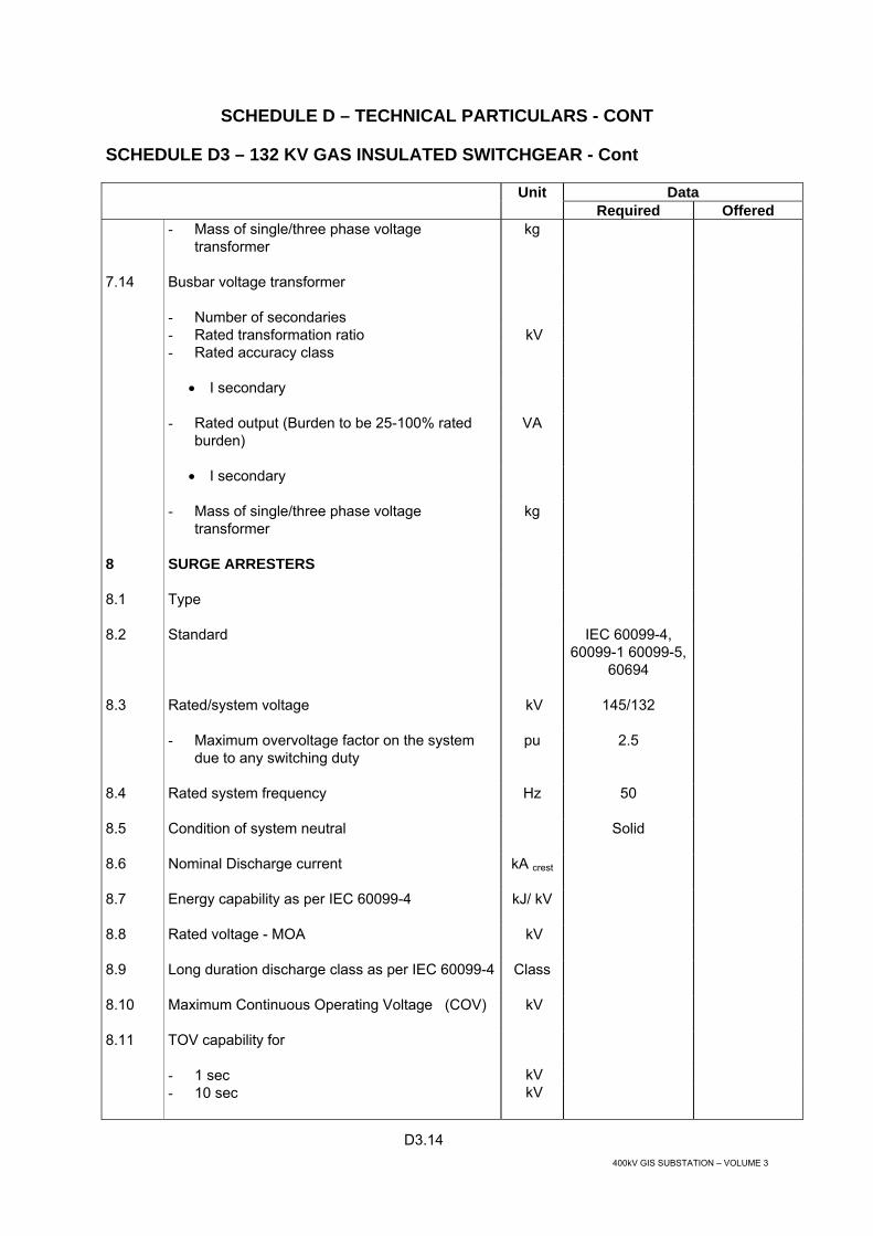
Unit Data Required Offered - Mass of single/three phase voltage
transformer kg
7.14 Busbar voltage transformer
- Number of secondaries - Rated transformation ratio kV - Rated accuracy class
• I secondary
- Rated output (Burden to be 25-100% rated burden)
VA
• I secondary
- Mass of single/three phase voltage transformer
kg
8 SURGE ARRESTERS
8.1 Type
8.2
Standard IEC 60099-4, 60099-1 60099-5,
60694
8.3 Rated/system voltage
kV
145/132
- Maximum overvoltage factor on the system due to any switching duty
pu 2.5
8.4 Rated system frequency
Hz 50
8.5 Condition of system neutral
Solid
8.6 Nominal Discharge current
kA crest
8.7 Energy capability as per IEC 60099-4 kJ/ kV
8.8 Rated voltage - MOA
kV
8.9 Long duration discharge class as per IEC 60099-4
Class
8.10 Maximum Continuous Operating Voltage (COV)
kV
8.11 TOV capability for
- 1 sec kV - 10 sec kV

D3.15 400kV GIS SUBSTATION – VOLUME 3
SCHEDULE D – TECHNICAL PARTICULARS - CONT
SCHEDULE D3 – 132 KV GAS INSULATED SWITCHGEAR - Cont
Unit Data Required Offered 8.12 Maximum residual voltage with current wave
- Switching Surges - 1kA / 2kA kV - 8/20 μs - 5kA kV - 8/20 μs - 10kA kV 8.14 Discharge current withstand strength
- High current (4/10 μs) KAp - Low current 2000A
Ap
8.15 Pressure relief capability
- High current (0.2 s) kA - Low current As per IEC
8.16 Rating of earth connections
kA/sec 40/1
8.17 Surge counter provided
Yes
9 CABLE BOX
9.1 Manufacturer & Place of manufacturing
9.2 Type of designation
9.3 Standards
IEC 60859
9.4 Rated voltage
kV 145
9.5 Rated lightning impulse withstand voltage phase to earth
kVp 650
9.6 Rated power frequency withstand voltage phase to earth
kV 275
9.7 Cable HV test withstand capability
kV
9.8 Rated frequency
Hz 50
9.9 Rated normal current at 40oC
A
9.10 Required current at 50oC (Contractor to confirm by calculation)
A
9.11 Rated short time withstand current (1s)
kA 40
9.12 Rated peak withstand current
kA 80
9.13 Total mass of three phase cable box complete
kg

D3.16 400kV GIS SUBSTATION – VOLUME 3
SCHEDULE D – TECHNICAL PARTICULARS - CONT
SCHEDULE D3 – 132 KV GAS INSULATED SWITCHGEAR - Cont
Unit Data Required Offered 10 MANUFACTURER QUALITY SYSTEM IN
ACCORDANCE TO ISO 9000, 9001, 9002, 9003 AND 9004
Yes
10.1 Date of issue
Latest
10.2 Validity
Valid Certificates –Yes
11 TYPE TEST CERTIFICATE TO BE ISSUED BY INDEPENDENT LABORATORY OR INDEPENDENTLY WITNESSED TYPE TEST CERTIFICATE TO BE SUBMITTED
Yes

D4.1 400kV GIS SUBSTATION – VOLUME 3
SCHEDULE D – TECHNICAL PARTICULARS - CONT
SCHEDULE D4 – 132 KV OPEN TERMINAL SWITCHGEAR
Unit Data Required Offered 1 GENERAL
1.1 Standards
IEC IEC 62271-100, 62271-102, 60694,
60233, 60044, 60186, 60383,
60815
1.2 Rated voltage
kV 145
1.3 System Voltage
kV 132
1.4 Rated frequency
Hz 50
1.5 Rated lightning impulse withstand voltage
Phase to earth kVp 650 Across the isolating distance kVp 750 1.6 Rated power frequency withstand voltage
Phase to earth kV 275 Across the isolating distance kV 315 1.7 Rated short-time withstand current (1 s)
kA 40
1.8 Rated peak withstand current
kA 62.5
1.9 Rated Current – Cable Feeder at 50 oC (Contractor to confirm by calculation) A 1600 (or to suit) 1.10 Material of HV conductor
Aluminium
1.11 Material of contacts
Bi-metallic
1.12 Minimum factors of safety for switchgear
Busbars or other connections based on elastic limit
2.5
Complete insulators based on electro-mechanical test
2.5
Insulator metal fittings based on elastic limit 2.5
Steel structures based on elastic limit of tension members and on crippling loads of compression members
2.5
Foundations for structures against overturning or uprooting under maximum simultaneous working loadings
2.5

D4.2 400kV GIS SUBSTATION – VOLUME 3
SCHEDULE D – TECHNICAL PARTICULARS - CONT
SCHEDULE D4 – 132 KV OPEN TERMINAL SWITCHGEAR - Cont
Unit Data Required Offered 1.13 Creepage distance (based on Um)
mm/ kV 31
1.14 Seismic factor
UBC Zone 3

D4.3 400kV GIS SUBSTATION – VOLUME 3
SCHEDULE D – TECHNICAL PARTICULARS - CONT
SCHEDULE D4 – 132 KV OPEN TERMINAL SWITCHGEAR - Cont
Unit Data Required Offered 2 CAPACITIVE VOLTAGE TRANSFORMERS
2.1 Type
Capacitive
2.2 Standards
IEC 60186, IEC/PAS 60044-
5:2002
2.3 Maximum permissible partial discharge level Um
pC 10
2.4 Maximum permissible partial discharge level 1.2Um /√3
pC 5
2.5 Method of suppressing ferroresonance phenomena
2.6 Line voltage transformer
2.7 Number of secondaries
2
Rated transformation ratio kV 132/√3 / 0.11/√3 /0.11/√3
Rated accuracy class
I secondary 3P/1.0 II secondary
3P
Rated output (burden to be 25-100% rated burden)
I secondary VA II secondary
VA
Mass of single phase voltage transformer
kg

D4.4 400kV GIS SUBSTATION – VOLUME 3
SCHEDULE D – TECHNICAL PARTICULARS - CONT
SCHEDULE D4 – 132 KV OPEN TERMINAL SWITCHGEAR - Cont
Unit Data Required Offered 3 BUSBARS AND CONNECTIONS
3.1 Type (flexible or tubular)
3.2 Material
3.3 Short-circuit current rating / duration
kA/s 40/1
3.4 Normal current rating at 40oC
A
at 50 oC
A 1600
3.5 Maximum continuous current rating
A
3.6 Flexible conductors stranding nominal cross-sectional area outer diameter no. of conductors per bundle spacing between conductors
mm2
mm
mm
3.7 Tubular conductors nominal cross-sectional area outer diameter inner diameter
mm2
mm
mm
3.8 Maximum stress at surface of flexible conductor
kV/mm
3.9 Radio influence voltage level measured at 1.1 times Us/√3 at 1 MHz
µV

D4.5 400kV GIS SUBSTATION – VOLUME 3
SCHEDULE D – TECHNICAL PARTICULARS - CONT
SCHEDULE D4 – 132 KV OPEN TERMINAL SWITCHGEAR - Cont
Unit Data Required Offered 4 POST TYPE INSULATORS
4.1 Type designation
4.2 Insulator material
4.3 Number of units in complete post insulator
4.4 Length of each unit
mm
4.5 Mass of complete post insulator
kg
4.6 Maximum cantilever working load (complete post insulator)
N
4.7 Minimum cantilever breaking load, upright (complete post insulator)
N
4.8 Power frequency withstand voltage dry: wet
kV
4.9 Basic insulation level
kVp
4.10 Minimum dry/wet switching surge withstand level
kVp
4.11 Radio influence voltage level measured at 1.1 times Us/√3 at 1 MHz
µv

D4.6 400kV GIS SUBSTATION – VOLUME 3
SCHEDULE D – TECHNICAL PARTICULARS - CONT
SCHEDULE D4 – 132 KV OPEN TERMINAL SWITCHGEAR - Cont
Unit Data Required Offered 5 TENSION AND SUSPENSION
INSULATORS
5.1 Type designation
5.2 Insulator material
5.3 Number of units in string
mm
5.4 Greatest diameter of units
mm
5.5 Distance between centres of units
mm
5.6 Length of string, overall
mm
5.7 Mass of string complete with all fittings
kg
5.8 Maximum working load
N
5.9 Power frequency withstand voltage of complete string
kV
5.10 Basic insulation level of complete string
kVp
5.11 Minimum wet switching surge withstand level of complete string
kVp
5.12 Radio influence voltage measured at 1.1 times Us/√3 at 1 MHz
µv

D4.7 400kV GIS SUBSTATION – VOLUME 3
SCHEDULE D – TECHNICAL PARTICULARS - CONT
SCHEDULE D4 – 132 KV OPEN TERMINAL SWITCHGEAR - Cont
Unit Data Required Offered 6 LINE TRAPS
6.1 Maker's type and designation
6.2 Main coil insulation – class
6.3 Read continuous current
A
6.4 Rated short time current (1 second/3 seconds) kA
6.5 Inductance at 50 Hz
mH
6.6 Insulating level across line traps at:
6.7 Power frequency
6.8 Impulse
6.9 Rated voltage level of protective device
kV
6.10 Centre frequency
kHz
6.11 Bank width of blocking range
kHz
6.12 Self resonant frequency
kHz
6.13 Tapping loss
db
6.14 Blocking impedance
Ω
6.15 Total mass
kg

D5.1 400kV GIS SUBSTATION – VOLUME 3
SCHEDULE D – TECHNICAL PARTICULARS - CONT
SCHEDULE D5 - 11 KV (TERTIARY) METALCLAD SWITCHGEAR
Unit Data Required Offered 1 GENERAL
1.1 Manufacturer & Place of Manufacturing
1.2 Type designation
1.3 Type of Switchgear
Metal clad - air insulated, indoor switchgear with Vacuum Circuit
Breaker
1.4 Standards
IEC 60298, 62271-100,
60694, 60529
1.5 Number of years equipment of identical design has been in service
Years
1.6 Rated voltage
kV 12
1.7 Rated normal current
At 50oC (contractor to confirm by calculation) − Incoming bay, busbar & bus-section bay A 4000 − Outgoing bay A 1600/600 to suit 1.8 Rated frequency
Hz 50
1.9 Rated lightning impulse withstand voltage
− Phase to earth kV 95
− Across the isolating distance KV 110 1.10 Rated power frequency withstand voltage
− Phase to earth KV 38 − Across the isolating distance KV 45 1.11 Partial discharge test voltage
KV IEC 60270
1.12 Rated short-time withstand current (1s)
KA 50
1.13 Rated peak withstand current
KA 125

D5.2 400kV GIS SUBSTATION – VOLUME 3
SCHEDULE D – TECHNICAL PARTICULARS - CONT
SCHEDULE D5 - 11 KV (TERTIARY) METALCLAD SWITCHGEAR - Cont
Unit Data Required Offered 1.14 Type of busbars
Single
1.15 Method of earthing
− Busbars side − Line side 1.16 Minimum subdivision of cubicles at compartments
Busbar/ CTs/
Circuit Breaker/ Cable/ VTs/Relay
compartment
1.17 Are busbars segregated
− Between phases Yes − Between cubicles Yes 1.18 Material of cover
Metallic
1.19 Material of partitions
Metallic
1.20 Material of shutters
Metallic/Earthed
1.21 Busbars and joints fully encapsulated
Yes
1.22 Busbar and feeder shutters lockable with individual manual and automatic features
Yes
1.23 Protection class
− General IP41 − Busbars, cable compartment, internal partitions IP3XD − Circuit breaker compartment
• Door closed • Door open
IP41 IPXX
− LV compartment IP41 − Shutters and spouts
− Pressure relief device/flaps IP4X
IP 5X
1.24 The way of securing (opening/closing of doors)
Hinged doors
1.25 Material of HV conductor
Copper
1.26 Material of contacts
Silver-plated copper
1.27 Type of pressure relief device
1.28 Method of personnel protection in case of operation of pressure relief device

D5.3 400kV GIS SUBSTATION – VOLUME 3
SCHEDULE D – TECHNICAL PARTICULARS - CONT
SCHEDULE D5 - 11 KV (TERTIARY) METALCLAD SWITCHGEAR - Cont
Unit Data Required Offered 1.29 Total mass of switchgear (average per bay)
kg
1.30 Minimum factors of safety for switchgear (minimum 2.5)
− Busbars or other connection based on elastic limit
2.5
− Complete insulators based on electro-mechanical test
2.5
− Insulator metal fittings based on elastic limit 2.5 − Steel structures based on elastic limit of tension
members and on crippling loads of compression members
2.5
− Foundations for structures against overturning or uprooting under maximum simultaneous working loading
2.5
1.31 Manufacturer quality assurance according to ISO 9000, 9001, 9002, 9003 and 9004
Yes
1.32 Type test certificate to be issued by Independent laboratory or independently witnessed type test certificate available
Yes
1.33 Emergency manual trip facility (during failure of DC supply)
Yes
2 CIRCUIT BREAKER
2.1 Manufacturer & Place of manufacturing
2.2 Type designation
2.3 Type
Vacuum, Truck mounted,
withdrawable
2.4 Fully encapsulated
Yes
2.5 Standards
IEC 60298, 62271-100,
60694, 60427
2.6 Rated voltage
kV 12
2.7 Rated normal current at 40oC (Incomer/bus section; Feeder)
A
2.8 Required current at 50oC (Incomer/bus section; Feeder) (Contractor to confirm by calculation)
A 4000/1600/630

D5.4 400kV GIS SUBSTATION – VOLUME 3
SCHEDULE D – TECHNICAL PARTICULARS - CONT
SCHEDULE D5 - 11 KV (TERTIARY) METALCLAD SWITCHGEAR - Cont
Unit Data Required Offered 2.9 Rated frequency
Hz 50
2.10 Rated lightning impulse withstand voltage
− Phase to earth kVp 95 − Across the isolating distance
kVp 110
2.11 Rated power frequency withstand voltage
− Phase to earth kV 38 − Across the isolating distance
kV 45
2.12 Rated short-time withstand current (1 s)
kA 50
2.13 Rated peak withstand current
kAp 125
2.14 Rated operating sequence
O-0.3 sec - - CO - 3 min - CO
2.15 Rated making current
kA 125
2.16 Rated breaking current (symmetrical)
kA 50
2.17 Rated breaking current (asymmetrical)
kA To IEC 62271-100
2.18 Rated breaking current under out of phase conditions
kA
2.19 First pole to clear factor
2.20 Rated line charging breaking current
A
2.21 Rated cable charging breaking current
A
2.22 Rated small inductive breaking current of - unloaded transformer - reactor
A
2.23 Maximum overvoltage factor on any switching duty
pu <2.5
2.24 If the Overvoltage factor above, is in excess of 2.5 pu, then detail steps taken to protect the system from overstressing, by the use of suitable Metal-Oxide surge arresters
2.25 Maximum peak value of switching overvoltage when interrupting capacitive currents
kV
2.26 Maximum peak value of switching over-voltage when interrupting low inductive and reactor currents
kV

D5.5 400kV GIS SUBSTATION – VOLUME 3
SCHEDULE D – TECHNICAL PARTICULARS - CONT
SCHEDULE D5 - 11 KV (TERTIARY) METALCLAD SWITCHGEAR - Cont
Unit Data Required Offered 2.27 Maximum total break time (trip initiation to final arc
extinction)
ms 60
2.28 Opening time (trip initiation to contact separation)
− Without current ms − With 100% rated breaking current ms 2.29 Maximum time interval between opening of first and
last phase of three phase circuit breakers
ms
3
2.30 Closing time from energisation of close coil to latching of circuit breaker in fully closed position
ms
2.31 Making time (energisation of close coil to contact touch)
− Without current ms − With 100% rated current ms 2.32 Maximum time interval between closure of first and
last phase of three phase circuit breaker
ms 3
2.34 Mechanical life of CB and Mechanism in number of operations
min 5000
2.35 Electrical contact life at rated current in No. of operations
2.36 Electrical contact life at 100% fault current in No. of operations
10
2.37 Internal arcing tests in the switchgear enclosure to IEC 60298 – Annex AA
Adjacent compartments
are not affected
2.38 Mechanical means for withdrawal
yes
2.39 Type of operating mechanism
3 pole
2.40 Manual spring discharge facility
Yes
2.41 Interlock facilities complying with requirements of specification
Yes
2.42 Type of power device
− For closing Motor-Spring − For opening Spring 2.43 Hand charging facility Yes

D5.6 400kV GIS SUBSTATION – VOLUME 3
SCHEDULE D – TECHNICAL PARTICULARS - CONT
SCHEDULE D5 - 11 KV (TERTIARY) METALCLAD SWITCHGEAR - Cont
Unit Data Required Offered 2.44 Charging time
S
2.45 Number of trip coils
1
2.46 Number of close coils
1
2.47 Nominal control and operating voltage
V 110 DC
2.48 Nominal heater voltage
V 220
2.49 Rated power of trip coil
W
2.50 Rated power of close coil
W
2.51 Rated motor power
W
2.52 Does earthing of truck remain effective until fully withdrawn
Yes
2.53 Total load of heaters for circuit breaker
W
2.54 Mass of circuit breaker complete (three pole set)
kg
2.55 Partial discharge test voltage
kV IEC 60270
2.56 Manufacturer quality assurance according to ISO 9000, 9001, 9002, 9003 and 9004
Yes
2.57 Type test certificate to be issued by independent laboratory or independently witnessed type test certificate available
Yes
3 BUSBARS
3.1 Rated current at 50oC
− Manufacturer’s Standard A − Corresponding site rating A 3.2 Maximum temperature rise
oC
3.3 Cross Section
mm2
3.4 Material of barriers between units
3.5 Insulation of Busbars:
− Material − Maximum working temperature oC

D5.7 400kV GIS SUBSTATION – VOLUME 3
SCHEDULE D – TECHNICAL PARTICULARS - CONT
SCHEDULE D5 - 11 KV (TERTIARY) METALCLAD SWITCHGEAR - Cont
Unit Data Required Offered 3.6 Type test certificate to be issued by independent
laboratory or independently witnessed type test certificate available
Yes
4 EARTHING SWITCH
4.1 Manufacturer & Place of Manufacturing
− at busbar side − at line side 4.2 Type designation
− at busbar side − at line side 4.3 Type of operating mechanism
Manual
4.4 Standards
IEC 62271-102
4.5 Rated voltage
kV 12
4.6 Rated frequency
Hz 50
4.7 Rated lightning impulse withstand voltage phase to earth
kV 95
4.8 Rated power frequency withstand voltage phase to earth
kV 38
4.9 Rated short time (1 s) current
kA 50
4.10 Peak Current
kAp 125
4.11 Total mass of three phase complete earthing switch
− at busbar side kg − at line side kg 4.12 Type of contacts
− Moving Copper − Fixed Copper 4.13 Moving contacts are directly connected to earthing
system via copper connectors
Yes
4.14 Continuous running earth bar has been provided Yes

D5.8 400kV GIS SUBSTATION – VOLUME 3
SCHEDULE D – TECHNICAL PARTICULARS - CONT
SCHEDULE D5 - 11 KV (TERTIARY) METALCLAD SWITCHGEAR - Cont
Unit Data Required Offered 5 CURRENT TRANSFORMER
5.1 Manufacturer & Place of manufacturing
5.2 Type
Cast-resin multi-core, multi-ratio
indoor
5.3 Type of primary winding (e.g. bar, wound, etc.)
5.4 Standards
IEC 60044-1
5.5 Rated voltage
kV 12
5.6 Rated lightning impulse withstand voltage phase to earth
kV 95
5.7 Rated power frequency withstand voltage phase to earth
kV 38
5.8 Partial discharge test voltage
kV IEC 60270
5.9 Rated frequency
Hz 50
5.10 Rated continuous thermal current at 50oC
Rated extended primary current
5.11 Rated short-time withstand current (1 s)
kA 50
5.12 Rated dynamic current
kA 125
5.13 Are earthed metal screens fitted between primary and secondary windings
5.14 Details of all current transformers are to be provided by the Contractor after contract award
- Type designation - Number of cores - Rated extended primary current in percentage of
rated primary current
- Ratio (TR – turns ratio) -
• I core A • II core A • III core A

D5.9 400kV GIS SUBSTATION – VOLUME 3
SCHEDULE D – TECHNICAL PARTICULARS - CONT
SCHEDULE D5 - 11 KV (TERTIARY) METALCLAD SWITCHGEAR - Cont
Unit Data Required Offered 6 VOLTAGE TRANSFORMERS (3-phase sets to be
provided)
6.1 Manufacturer & Place of manufacturing
6.2 Type designation for
− Line transformer − Busbar transformer − Power transformer bay 6.3 Type
Inductive cast -
resin single pole insulated
6.4 Standards
IEC 60044-2
6.5 Rated voltage
kV 12
6.6 Rated frequency
Hz 50
6.7 Rated lightning impulse phase to earth
kV 95
6.8 Rated power frequency withstand voltage phase to earth
kV 38
6.9 Partial discharge test voltage
kV IEC 60270
6.10 Type of primary isolation
Drawout
6.11 Line voltage transformer & Busbar Voltage Transformer
− Number of secondaries − Rated transformation ratio kV − Rated accuracy class − Rated output VA − Total mass of three phase voltage transformer
complete
kg
7 Manufacturer quality system in accordance with ISO 9000, 9001, 9002, 9003 and 9004
Yes
8 Type test certificate to be issued by independent laboratory or independently witnessed type test certificate available.
Yes

D6.1 400kV GIS SUBSTATION – VOLUME 3
SCHEDULE D – TECHNICAL PARTICULARS - CONT
SCHEDULE D6 - CRANE FOR GIS BUILDING
Unit Data Required Offered 1 Manufacturer
2 Type
Overhead travelling
3 Capacity
t
4 Test load, dynamic
%
5 Operating speed:
- Hoist M/min - Trolley travel M/min - Bridge travel M/min 6 Operating power source and terminal voltage
- Voltage V 380/220 - Frequency Hz 50 7 Dimensions
- Span m - Length of runway m - Total lift of hook m 8 Crane drive motors
- Manufacturer - Type 9 Trolley drive motors
- Manufacturer - Type 10 Operator/Maintenance cage provided with trolley
yes
11 Enclosed current collector
yes
12 Hoist
- Manufacturer - Type - Type of control Pendant or
infrared
13 Total required power
kW
14 Weights
- Bridge complete t - Trolley complete t - Runway complete t

D6.2 400kV GIS SUBSTATION – VOLUME 3
SCHEDULE D – TECHNICAL PARTICULARS - CONT
SCHEDULE D6 - CRANE FOR GIS BUILDING - CONT
Unit Data Required Offered 15 Reference Standards
BS 466, 2573
16 Manufacturer's Quality Assurance
ISO 9000 to 9004
17 Type Test Certificates (to be issued by independent laboratory or independently witnessed type test certificate)
yes

D7.1 400kV GIS SUBSTATION – VOLUME 3
SCHEDULE D – TECHNICAL PARTICULARS - CONT
SCHEDULE D7 – 400/138.6 KV POWER TRANSFORMERS
Item Description Unit Data No Required Provided 1 Description of transformers
Transmission autotransformer
2 Type of transformers:
2.1 Indoor or outdoor
Outdoor
2.2 Shell or core
2.3 Auto or separate windings
Auto
2.4 Three phase or single phase units
Single
2.5 Cooling (IEC letter symbols)
ONAF1/ANAFZ/ANAN
3 Site Conditions
3.1 Altitude above sea level
m
Less than 1000m
3.2 Air temperature minimum
°C
-10
3.3 Air temperature maximum
°C
+55
4 IEC ratio power at terminals of:
4.1 HV winding
MVA
250
4.2 LV winding
250
4.3 Tertiary winding
MVA
75
5 Continuous maximum ratings at winding terminals according to tapping position when operating under site conditions:
5.1 HV winding
MVA
250
5.2 LV winding
MVA
250
5.3 Tertiary winding
MVA
75
6 Maximum ONAN and ONAF ratings of winding terminals irrespective of tapping position, when operating under site conditions
6.1 ONAN ratings:
6.1.1 HV winding
MVA 150
6.1.2 LV winding
MVA 150
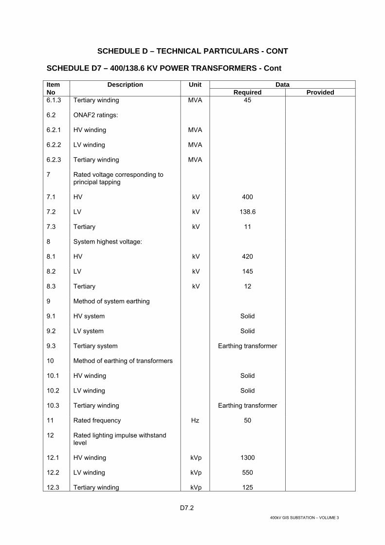
D7.2 400kV GIS SUBSTATION – VOLUME 3
SCHEDULE D – TECHNICAL PARTICULARS - CONT
SCHEDULE D7 – 400/138.6 KV POWER TRANSFORMERS - Cont
Item Description Unit Data No Required Provided 6.1.3 Tertiary winding
MVA
45
6.2 ONAF2 ratings:
6.2.1 HV winding
MVA
6.2.2 LV winding
MVA
6.2.3 Tertiary winding
MVA
7 Rated voltage corresponding to principal tapping
7.1 HV
kV
400
7.2 LV
kV
138.6
7.3 Tertiary
kV
11
8 System highest voltage:
8.1 HV
kV
420
8.2 LV
kV
145
8.3 Tertiary
kV
12
9 Method of system earthing
9.1 HV system
Solid
9.2 LV system
Solid
9.3 Tertiary system
Earthing transformer
10 Method of earthing of transformers
10.1 HV winding
Solid
10.2 LV winding
Solid
10.3 Tertiary winding
Earthing transformer
11 Rated frequency
Hz
50
12 Rated lighting impulse withstand level
12.1 HV winding
kVp
1300
12.2 LV winding
kVp
550
12.3 Tertiary winding kVp 125

D7.3 400kV GIS SUBSTATION – VOLUME 3
SCHEDULE D – TECHNICAL PARTICULARS - CONT
SCHEDULE D7 – 400/138.6 KV POWER TRANSFORMERS - Cont
Item Description Unit Data No Required Provided 13 Switching impulse withstand level
13.1 HV winding
kVp
1050
13.2 LV winding
kVp
-
13.3 Tertiary winding
kVp
-
14 Maximum system symmetrical rms fault current (1 phase or 3 phase) at the terminals of the transformer which the windings must be capable of withstanding
14.1 HV terminals
kA
40
14.2 LV terminals
kA
40
14.3 Tertiary terminals
kA
50
14.4 Asymmetrical crest factor
2.55
15 Phase connections
15.1 IEC vector group symbols
YNyn0d11
15.2 Whether links are required for alternative IEC vector group
No
15.3 Alternative vector group required
-
16 Windings
16.1 Common winding
Graded
16.2 Series winding
Graded
17 Whether one winding is a stabilising winding only
If so, whether the winding is to be brought out to If so, whether the winding is to be brought out to separate bushing insulator(s) or cable box terminals for test purposes (For earthing see Item 10)
No -
18 Whether `on-load' or `off-circuit' tap changing equipment or links are required
On load

D7.4 400kV GIS SUBSTATION – VOLUME 3
SCHEDULE D – TECHNICAL PARTICULARS - CONT
SCHEDULE D7 – 400/138.6 KV POWER TRANSFORMERS - Cont
Item Description Unit Data No Required Provided 19 Tapping quantities transformer
designation
HV LV
19.1 Minimum voltage ratio 366.6 145.2
19.2 Maximum current tapping (HV)
382.6 145.2
19.3 Maximum current tapping (LV)
400 125.4
19.4 Principal tapping
400 138.6
19.5 Maximum voltage tapping (LV) 400 145.2
19.6 Maximum voltage ratio
400 118.8
See note below
220 Tapping steps:
20.1 Approximate size
%
1
20.2
Approximate number 20
21 Excess of continuously applied voltage over tapping voltage for any tapping when transformer is delivering tapping power
5%
22 Whether tappings are preferred on any particular winding
22.1 On common winding
Yes
22.2 IEC category of voltage variation
CFVV
22.3 On series winding
No
22.4 IEC category of voltage variation
-
22.5 On Tertiary winding
No
22.6 IEC category of voltage variation
-
23 Whether on-load tap changing equipment shall be suitable for supervisory control and indication
Yes
24 Remote tap change control panel

D7.5 400kV GIS SUBSTATION – VOLUME 3
SCHEDULE D – TECHNICAL PARTICULARS - CONT
SCHEDULE D7 – 400/138.6 KV POWER TRANSFORMERS - Cont
Item Description Unit Data No Required Provided 24.1 Whether required
Yes
24.2 Exterior finish
To match existing plant
25 Automatic voltage control equipment
25.1 Whether required
Yes
25.2 Whether to be suitable for remote adjustment of setting
Yes
26 Whether equipment shall be provided to permit automatic synchronised operation of on-load tap changing equipment in parallel with similar transformers
Yes
27 Whether gas and oil actuated relay shall be fitted to each tap selector compartment
Yes
28 Bushing insulators or cable boxes for line terminals
28.1 HV and LV
Oil/SF6 bushing or Oil/Air as applicable
28.2 Tertiary
Cable box*
28.3 Filling medium for cable boxes
Air
29 Whether disconnecting chambers are required
Yes
30 Bushing insulator or cable box for neutral terminals, if any:
30.1 HV
Bushing
30.2 LV
Bushing
30.3 Tertiary -
31 Whether accommodation for current transformers shall be provided on:
31.1 HV terminals
Yes
31.2 LV terminals
Yes
31.3 Common winding neutral end
Yes
31.4 Tertiary terminals Yes
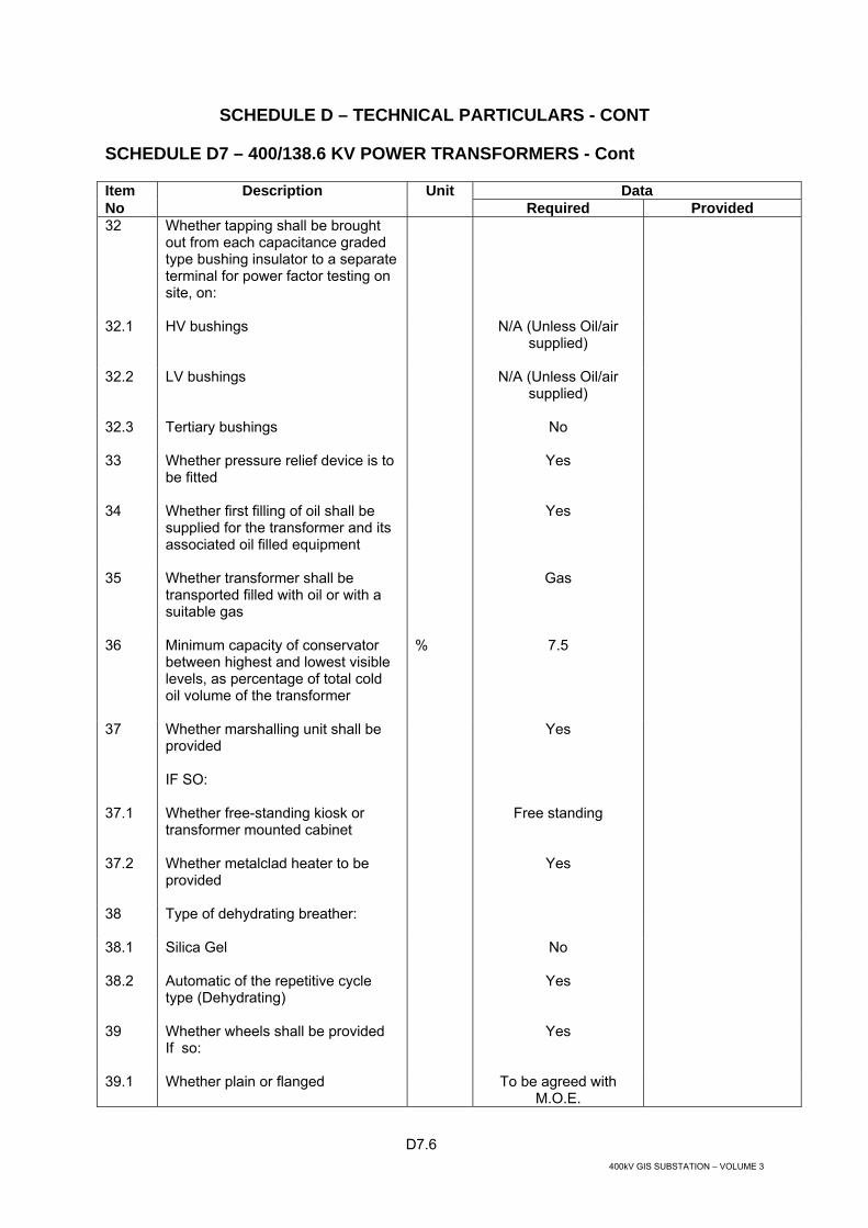
D7.6 400kV GIS SUBSTATION – VOLUME 3
SCHEDULE D – TECHNICAL PARTICULARS - CONT
SCHEDULE D7 – 400/138.6 KV POWER TRANSFORMERS - Cont
Item Description Unit Data No Required Provided 32 Whether tapping shall be brought
out from each capacitance graded type bushing insulator to a separate terminal for power factor testing on site, on:
32.1 HV bushings
N/A (Unless Oil/air supplied)
32.2 LV bushings
N/A (Unless Oil/air supplied)
32.3
Tertiary bushings No
33 Whether pressure relief device is to be fitted
Yes
34 Whether first filling of oil shall be supplied for the transformer and its associated oil filled equipment
Yes
35 Whether transformer shall be transported filled with oil or with a suitable gas
Gas
36 Minimum capacity of conservator between highest and lowest visible levels, as percentage of total cold oil volume of the transformer
% 7.5
37 Whether marshalling unit shall be provided IF SO:
Yes
37.1 Whether free-standing kiosk or transformer mounted cabinet
Free standing
37.2 Whether metalclad heater to be provided
Yes
38 Type of dehydrating breather:
38.1 Silica Gel
No
38.2 Automatic of the repetitive cycle type (Dehydrating)
Yes
39 Whether wheels shall be provided If so:
Yes
39.1 Whether plain or flanged
To be agreed with M.O.E.

D7.7 400kV GIS SUBSTATION – VOLUME 3
SCHEDULE D – TECHNICAL PARTICULARS - CONT
SCHEDULE D7 – 400/138.6 KV POWER TRANSFORMERS - Cont
Item Description Unit Data No Required Provided 39.2 Whether required to turn through
90°
Yes
39.3 Gauge of track
To be agreed with M.O.E.
40 Whether winding or oil temperature indicators are required
Yes
40.1 HV winding wti
Yes
40.2 LV winding wti
Yes
40.3 Tertiary winding (wti)
Yes
40.4 Oil temperature indicator
Yes
41 Whether winding temperature indicator remote repeaters are required
No
42 Whether the forced cooling equipment is to be operated automatically from contacts on the winding temperature indicator
Yes
43 Whether electrical energy will be provided on site for erection purposes IF SO: Maximum available power
kVA
To be agreed with M.O.E
44 Supply voltage for transformer auxiliaries
V
380/220
45 Whether control and instrument wiring shall conform to specified colour code
Yes
46 Impulse tests: (state whether "type" or "routine")
Routine
46.1 Whether recurrent surge oscillograph tests are to be carried out
Yes
46.2 Whether HV winding to be directly impulse tested
Yes

D7.8 400kV GIS SUBSTATION – VOLUME 3
SCHEDULE D – TECHNICAL PARTICULARS - CONT
SCHEDULE D7 – 400/138.6 KV POWER TRANSFORMERS - Cont
Item Description Unit Data No Required Provided 46.2.1 Whether chopped waves to be
included
Yes
46.2.2 For tests of HV winding impedance to earth from:
- Other HV terminals - LV terminals - Tertiary terminals
Earthed Earthed except tested
phase Resistance earthed
46.3 Whether LV winding to be directly impulse tested
Yes
46.3.1 Whether chopped waves to be included
Yes
46.3.2 For tests on LV winding, impedance to earth from: - Other LV terminals - HV terminals - Tertiary terminals
Earthed Earthed except tested
phase Resistance earthed
46.4 Whether tertiary winding to be directly impulse tested
Yes
46.4.1 Whether chopped waves to be included
No
46.4.2 For tests on tertiary winding, impedance to earth from: - Other tertiary terminals - HV terminals - LV terminals
Earthed Earthed except for
tested phase Earthed except for
tested phase
47 Dielectric tests on windings with Um » 300 kV, non-uniform insulation:
47.1 Whether tests shall be conducted in accordance with Method 1 or Method 2, to IEC 60076-3
Method 1
47.2 If Method 2, voltage level U2 at which partial discharge measurements shall be made
48 Whether zero phase sequence impedance test required
Yes
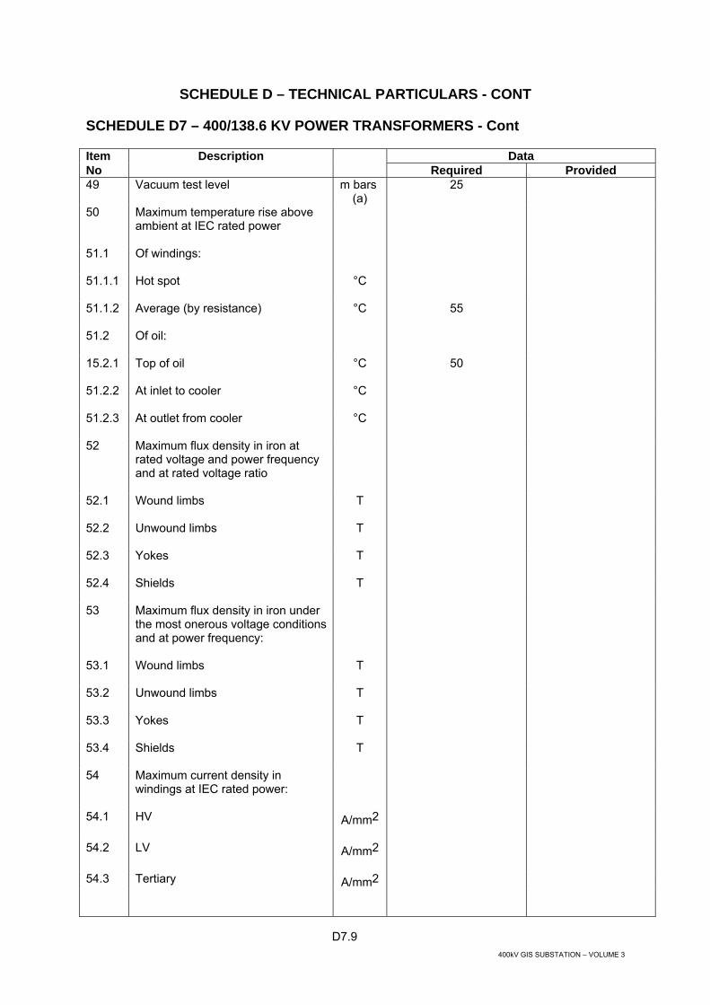
D7.9 400kV GIS SUBSTATION – VOLUME 3
SCHEDULE D – TECHNICAL PARTICULARS - CONT
SCHEDULE D7 – 400/138.6 KV POWER TRANSFORMERS - Cont
Item Description Data No Required Provided 49 Vacuum test level
m bars
(a) 25
50 Maximum temperature rise above ambient at IEC rated power
51.1 Of windings:
51.1.1 Hot spot
°C
51.1.2 Average (by resistance)
°C
55
51.2 Of oil:
15.2.1 Top of oil
°C
50
51.2.2 At inlet to cooler
°C
51.2.3 At outlet from cooler
°C
52 Maximum flux density in iron at rated voltage and power frequency and at rated voltage ratio
52.1 Wound limbs
T
52.2 Unwound limbs
T
52.3 Yokes
T
52.4 Shields
T
53 Maximum flux density in iron under the most onerous voltage conditions and at power frequency:
53.1 Wound limbs
T
53.2 Unwound limbs
T
53.3 Yokes
T
53.4 Shields
T
54 Maximum current density in windings at IEC rated power:
54.1 HV
A/mm2
54.2 LV
A/mm2
54.3 Tertiary A/mm2

D7.10 400kV GIS SUBSTATION – VOLUME 3
SCHEDULE D – TECHNICAL PARTICULARS - CONT
SCHEDULE D7 – 400/138.6 KV POWER TRANSFORMERS - Cont
Item Description Unit Data No Required Provided 54.4 Tapping
A/mm2
55 Magnetising current (HV winding)
55.1 At 90% rated voltage
A
55.2 At 100% rated voltage
A
55.3 At 110% rated voltage
A
55.4 At the maximum voltage equivalent to the value quoted in Schedule D Part I
A
56 No load losses at rated voltage ratio and IEC rating (guaranteed value) :
kW
57 Input to cooling plant
kW
58 Load losses at 75°C and rated ONAF power:
i) On principal (normal) tapping,
58.1 Tap position number
58.2 HV /LV (guaranteed value)
kW
58.3 HV/ tertiary at tertiary rated power kW
58.4 LV/ tertiary winding at tertiary rated power
kW
ii) On tapping for maximum loss
58.5 Tap number
58.6 HV /LV (guaranteed value)
kW
58.7 HV/ tertiary at tertiary rated power
kW
58.8 LV/ tertiary winding at rated power
kW
59 Load losses at 75°C and rated ONAN power
kW
i) On principal (normal) tapping,
59.1 Tap position number
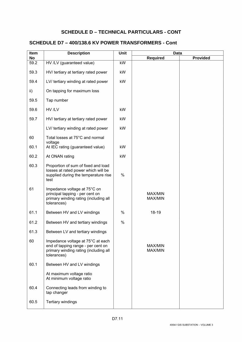
D7.11 400kV GIS SUBSTATION – VOLUME 3
SCHEDULE D – TECHNICAL PARTICULARS - CONT
SCHEDULE D7 – 400/138.6 KV POWER TRANSFORMERS - Cont
Item Description Unit Data No Required Provided 59.2 HV /LV (guaranteed value)
kW
59.3 HV/ tertiary at tertiary rated power
kW
59.4 LV/ tertiary winding at rated power
kW
ii) On tapping for maximum loss
59.5 Tap number
59.6 HV /LV
kW
59.7 HV/ tertiary at tertiary rated power
kW
LV/ tertiary winding at rated power
kW
60 Total losses at 75°C and normal voltage
60.1 At IEC rating (guaranteed value)
kW
60.2 At ONAN rating
kW
60.3 Proportion of sum of fixed and load losses at rated power which will be supplied during the temperature risetest
%
61 Impedance voltage at 75°C on principal tapping - per cent on primary winding rating (including all tolerances)
MAX/MIN MAX/MIN
61.1 Between HV and LV windings
%
18-19
61.2 Between HV and tertiary windings
%
61.3 Between LV and tertiary windings
60 Impedance voltage at 75°C at each end of tapping range - per cent on primary winding rating (including all tolerances)
MAX/MIN MAX/MIN
60.1 Between HV and LV windings At maximum voltage ratio At minimum voltage ratio
60.4 Connecting leads from winding to tap changer
60.5 Tertiary windings

D7.12 400kV GIS SUBSTATION – VOLUME 3
SCHEDULE D – TECHNICAL PARTICULARS - CONT
SCHEDULE D7 – 400/138.6 KV POWER TRANSFORMERS - Cont
Item Description Unit Data No Required Provided 61 Calculated thermal time constant:
61.1 Natural cooling
s
61.2 Forced cooling
s
62 Oil circulation (i.e. natural/partially directed/directed)
62.1 To the windings:
62.1.1 HV
62.1.2 LV
62.1.3 Tapping 62.1.4 Tertiary
62.2 Through the windings:
62.2.1 HV
62.2.2 LV
62.2.3 Tapping
62.2.4 Tertiary
63 Core construction
63.1 Taped/banded/bolted limbs
63.2 Taped/banded/bolted yokes
63.3 Taping/banding material
63.4 Number of limbs
63.5 Number of limbs wound
64 Type of joint in magnetic core (90% butt, overlap, mitre etc)
64.1 Whether tank or other flux shields are incorporated
64.2 Type of core steel
64.3 Specific loss of core steel at 1.5 tesla
W/kg

D7.13 400kV GIS SUBSTATION – VOLUME 3
SCHEDULE D – TECHNICAL PARTICULARS - CONT
SCHEDULE D7 – 400/138.6 KV POWER TRANSFORMERS - Cont
Item Description Unit Data No Required Provided 65 Voltage rating of neutral bushing or
cable box:
65.1 HV neutral
kV
65.2 LV neutral
kV
65.3 Tertiary neutral
kV
66 Type of on-load voltage control equipment:
66.1 Single or double compartment type etc
66.2 Manufacturer's type designation
67 Tappings
67.1 Arrangement of tappings (Linear, Coarse/fine, Reversing)
67.2 Which winding is tapped and where (e.g. neutral end)
67.3 Size of step as percentage of winding rated voltage
%
67.4 Number of steps
68 Minimum thickness of tank base plate
Base plate Side plate
Base plate
Side plate
68.1 With flat base 19 6 Length not exceeding 2500mm 19 6 Length exceeding 2500mm not
exceeding 7500mm
25 9
Length exceeding 2500mm
32 16
68.2 With fabricated underbase Length not exceeding 2500mm 9 6 Length exceeding 2500mm 12 9 68.3 Top
mm
69 Material of transformer tank
70 Thickness of radiator plates and/or cooling tubes
mm

D7.14 400kV GIS SUBSTATION – VOLUME 3
SCHEDULE D – TECHNICAL PARTICULARS - CONT
SCHEDULE D7 – 400/138.6 KV POWER TRANSFORMERS - Cont
Item Description Unit Data No Required Provided 71 Number of coolers or cooler banks
per transformers
72 Rating of each cooler or cooler bank
kW
73 Total oil required (including cooling system) litres
74 Filling medium of transformer tank for shipment
75 Total volume of conservator
litres
76 Volume of oil in conservator between the highest and lowest visible levels
litres
77 Mass of core and windings tonnes
78 Mass of copper required in the complete transformer kg
79 Mass of core laminations
kg
80 Total mass of complete transformer including cooling gear, voltage regulating equipment, all fittings and oil
tonnes
81 Mass of transformer as arranged for transport (heaviest part)
tonnes
82 Maximum noise level (`A' weighting)
dB
88
83 Dimensions of transformer arranged for transport:
83.1 Height
m
83.2 Width
m
83.3 Length
m
84 Time for which transformer can safely withstand 30 per cent over-voltage s

D7.15 400kV GIS SUBSTATION – VOLUME 3
SCHEDULE D – TECHNICAL PARTICULARS - CONT
SCHEDULE D7 – 400/138.6 KV POWER TRANSFORMERS - Cont
Item Description Unit Data No Required Provided 85 Whether any reactors, capacitors,
linear or non-linear resistors are immersed in the oil of the transformer or tap changer tank
86 Transformer magnetising characteristics (on nominal tapping), and allowable duration:
86.1 250 MVA TRANSFORMER VOLTAGE
ph-ph kV 360 400 440 480 520 560 600
MAGNETISINGCURRENT current/ph (A rms/ph) (s)
87 Flux-current (B-H curve for the
transformers):
88 Confirm that the life of the transformer will not be significantly reduced if subjected to the overvoltages specified in Schedule D Part I
YES/NO YES/NO
(Delete as applicable)

D8.1 400kV GIS SUBSTATION – VOLUME 3
SCHEDULE D – TECHNICAL PARTICULARS - CONT
SCHEDULE D8 - 400 KV SHUNT REACTORS
Item Description Unit Data No Required Provided 1 Description of reactor
1.1 Indoor or outdoor installation Outdoor
1.2 Shell or core construction
1.3 Gapped core or coreless type
1.4 Three phase or single phase units
Three or single
2 Site conditions
2.1 Altitude above sea level m Less than 1000m
2.2.1 Air minimum °C -10
2.2.2 Air maximum °C +55
3 Continuous maximum rating (CMR) when operating under site conditions:
50MVA
4 Rated frequency Hz 50
5 Rated voltage kV 420
6 Nominal voltage kV 400
7 Vector group symbol YN
8 Method of system earthing Solid - Effective
9 Method of earthing the reactors Not applicable
10 Type of cooling ONAN
11 Impulse withstand level (full wave 1.2/50 microsecond) under site conditions
kVp 1425
12 Whether star connected winding shall be fully insulated or graded
Graded
13 Bushing insulators or cable boxes or sealing ends for:
13.1 Line terminals Oil/SF6 bushing or Oil/Air as applicable
13.2 Neutral end terminals Bushing

D8.2 400kV GIS SUBSTATION – VOLUME 3
SCHEDULE D – TECHNICAL PARTICULARS - CONT
SCHEDULE D8 - 400 KV SHUNT REACTORS - Cont
Item Description Unit Data No Required Provided 14 Whether accommodation for current
transformers shall be provided on:
14.1 Line terminals Yes
14.2 Neutral end terminals Yes
15 Whether tapping shall be brought out from each capacitance graded type bushing insulator to a separate terminal for power factor testing on site
N/A (Unless Oil/Air Supplied)
16 Whether pressure release device is to be fitted
Yes
17 Whether first filling of oil shall be supplied for the reactor and its associated oil filled equipment
Yes
18 Whether reactor shall be transported filled with oil or a suitable gas
Gas
19 Minimum capacity of conservator between highest and lowest visible levels, as percentage of total cold oil volume of the reactor
7.5%
20 Whether marshalling kiosk or reactor mounted cabinet
Marshalling kiosk
21 Type of dehydrating breather:
21.1 Silica Gel No
21.2 Automatic of the repetitive cycle (Dehydrating)
Yes
22 Whether wheels are required If yes:
Yes
22.1 Whether plain or flanged To be agreed with M.O.E
22.2 Whether required to turn through 90°
Yes
22.3 Gauge of track To be agreed with M.O.E.
23 Whether oil temperature indicator is required
Yes

D8.3 400kV GIS SUBSTATION – VOLUME 3
SCHEDULE D – TECHNICAL PARTICULARS - CONT
SCHEDULE D8 -400 KV SHUNT REACTORS - Cont
Item Description Unit Data No Required Provided 24 Vacuum test level
m bars
(a)
25
25 IEC rated power
MVAr
26 IEC rated lightning impulse withstand voltage
kVp
27 Maximum temperature rise above ambient at IEC rated power
27.1 Of windings
27.1.1 Hot spot
°C
27.1.2 Average (by resistance)
°C
55
27.2 Of oil
27.2.1 Top oil
°C
50
27.2.2 At inlet to cooler
°C
27.2.3 At outlet to cooler
°C
28 Maximum flux density in iron at rated voltage and power frequency
28.1 Cores
T
28.2 Yokes
T
28.3 Shields
T
29 Maximum current density in winding at IEC rated power
A/mm²
30 Total losses at 75°C and rated voltage
kW
31 Impedance at 75°C at IEC rated voltage and IEC rated power
32 Resistance of windings at 75°C
ohms/phase
33 Type of winding
34 Conductor material (e.g. copper, work hardened copper etc.)
35 Conductor insulation

D8.4 400kV GIS SUBSTATION – VOLUME 3
SCHEDULE D – TECHNICAL PARTICULARS - CONT
SCHEDULE D8 - 400 KV SHUNT REACTORS - Cont
Item Description Unit Data No Required Provided 36 Calculated thermal time constant s
37 Type of joint in magnetic core (90° butt, overlap, mitre etc.)
37.1 Whether tank or other flux shields are incorporated
37.2 Type of core steel
37.3 Specific loss of core steel at 1.5 tesla
W/kg
38 Voltage rating of neutral bushing or cable box
kV
39 Minimum thickness of tank base plate
Base plate Side plate
Base plate
Side plate
39.1 With flat base
19 6
39.2 Length not exceeding 2500mm 19 6 Length exceeding 2500mm not
exceeding 7500mm
25 9
Length exceeding 2500mm
32 16
With fabricated underbase Length not exceeding 2500mm 9 6 Length exceeding 2500mm 12 9 39.3 Top
mm
40 Material of reactor tank
41 Thickness of radiator plates and/or cooling tubes
mm
42 Number of coolers or cooler banks per reactor
43 Rating of each cooler or cooler bank
kW
44 Total oil required (including cooling system)
litres
45 Filling medium of reactor tank for shipment
46 Total volume of conservator
litres

D8.5 400kV GIS SUBSTATION – VOLUME 3
SCHEDULE D – TECHNICAL PARTICULARS - CONT
SCHEDULE D8 - 400 KV SHUNT REACTORS - Cont
Item Description Unit Data No Required Provided 47 Volume of oil in conservator
between the highest and lowest visible levels
litres
48 Mass of core and winding
tonnes
49 Mass of copper required in the complete reactor
kg
50 Mass of core laminations
kg
51 Total mass of complete reactor including control gear, all fittings and oil
tonnes
52 Mass of reactor as arranged for transport (heaviest part)
tonnes
53 Maximum noise level (‘A’ weighing)
dB
54 Dimensions of reactor arranged for transport
54.1 Height
m
54.2 Width
m
54.3 Length
m
55 Departure from linearity of voltage/current characteristic at following percentages of rated voltage
55.1 110 per cent
A
55.2 120 per cent
A
55.3 130 per cent
A
55.4 Whether above values will be demonstrated by test

D9.1 400kV GIS SUBSTATION – VOLUME 3
SCHEDULE D – TECHNICAL PARTICULARS - CONT
SCHEDULE D9 – EARTHING TRANSFORMERS (11 KV TERTIARY)
Unit Data Required Offered 1 EARTHING TRANSFORMER
1.1 Manufacturer & Place of manufacturing
1.2 Type designation
1.3 Type
Three phase, oil immersed,
core type
1.4 Standards
IEC 60076-1, -2, -3, -5, -10,
60296 NEMA TR1
1.5 Mounting Outdoor, wheel
1.6 Rated voltage
kV 11
1.7 Rated frequency
Hz 50
1.8 Vector group
ZN
1.9 Cooling
ONAN
1.10 Method of earthing
1.10.1 HV winding Solid 1.11 Type (graded/non-graded) of windings
1.11.1 HV winding Non-graded 1.12 Rated voltage of windings
1.12.1 HV winding kV 11 1.13 Highest voltage for equipment
1.13.1 HV winding
kV 12

D9.2 400kV GIS SUBSTATION – VOLUME 3
SCHEDULE D – TECHNICAL PARTICULARS - CONT
SCHEDULE D9 – EARTHING TRANSFORMERS (11 KV TERTIARY) - Cont
Unit Data Required Offered 1.14 Rated lightning impulse withstand voltage at HV
Terminal
kV 95
1.15 Rated power frequency withstand voltage at
1.15.1 HV terminal
kV 38
1.16 HV neutral terminal
kV 38
1.17 Maximum temperature rise at rated power at:
1.17.1 Windings
K 55
1.17.2 Hot spot of windings
K 68
1.17.3 Top oil
K 50
1.17.4 Oil at inlet of cooler
K
1.17.5 Oil at outlet of cooler
K
1.17.6 Core
K
1.18 Losses at rated voltage and rated frequency
kW
1.19 Maximum current density at rated power:
1.19.1 HV winding
A/mm2
1.19.2 LV auxiliary winding
A/mm2
1.20 Symmetrical short circuit withstand current (duration 2 s) at:
1.20.1 HV terminal kA 50 1.21 Magnetising current (HV winding)
1.21.1 At 90% rated voltage
A
1.21.2 At 100% rated voltage
A
1.21.3 At 110% rated voltage A

D9.3 400kV GIS SUBSTATION – VOLUME 3
SCHEDULE D – TECHNICAL PARTICULARS - CONT
SCHEDULE D9– EARTHING TRANSFORMERS (11 KV TERTIARY) - Cont
Unit Data Required Offered 1.22 Maximum flux density in core at rated voltage, power
frequency
T
1.23 Limitation and withstanding of fault current in neutral for 30s
A To be calculated
1.24 Resistance of winding at 75°C:
1.24.1 HV side
Ω/phase
1.25 Zero phase sequence impedance of inter-star windings at 75°C
Ω/phase
1.26 Terminal connection
1.26.1 HV terminal Air-filled cable box
1.26.3 HV neutral terminal Air-filled cable box
1.27 Isolating link for test purposes (not required if separable connector allows testing)
1.28.1 HV terminal
Yes
1.29.2 LV terminal
No
1.30 Mounting of current transformer at
1.30.1 HV terminal
In tank
1.30.2 Neutral terminals
In tank or box
1.31 Current transformers
To suit
HV Neutral Number of cores
Rated extended primary current
Ratio (TR = turns ratio)
I core A II core
A
Class
I core II core

D9.4 400kV GIS SUBSTATION – VOLUME 3
SCHEDULE D – TECHNICAL PARTICULARS - CONT
SCHEDULE D9– EARTHING TRANSFORMERS (11 KV TERTIARY) - Cont
Unit Data Required Offered
Knee point voltage (Ek)
I core V II core
V
Exciting current (IE ) at Ek
I core mA II core
mA
Rated output (Burden to be 25-100% rated burden)
I core VA II core
VA
1.32 Oil:
1.32.1 Manufacturer
1.32.2 Type designation
1.32.3 Standards
IEC 60296
1.32.4 Minimum flash point
oC
1.32.5 Viscosity
At 20oC mm2/s At 50oC mm2/s At 80oC
mm2/s
1.32.6 Maximum dielectric strength for 1 min
kV
1.32.7 Dielectric factor
1.32.8 Acidity (neutralization value) mgKOH/g
1.33 Type of dehydrating breather (Non-sealed transformers)
Silicagel – automatic
recharge type
1.34 Conductor material (e.g. copper, work hardened copper, etc.):
1.34.1 HV windings
1.35 Conductor insulation:
1.35.1 HV winding
1.36 Calculated thermal time constant
min
1.37 Thickness of transformer tank

D9.5 400kV GIS SUBSTATION – VOLUME 3
SCHEDULE D – TECHNICAL PARTICULARS - CONT
SCHEDULE D9 – EARTHING TRANSFORMERS (11 KV TERTIARY) - Cont
Unit Data Required Offered 1.37.1 Sides
mm
1.37.2 Bottom
mm
1.37.3 Top
mm
1.38 Material of transformer tank
1.39 Thickness of radiator plates
mm
1.40 Total volume of conservator
litres
1.41 Masses of transformer
1.42 Core and coils
kg
1.43 Total mass excluded oil
kg
1.44 Oil mass • in tank kg • in radiators kg • total
kg
1.45 Total mass
kg
1.46 Mass of transformer as arranged for transport (heaviest part)
kg
1.47 Dimensions of transformer arranged for transport
Height m Width m Length m 1.48 Maximum noise level (to NEMA TR1)
dB 56
1.49 Vibration test (Y/N)
N
1.50 Conservator vessel, radiators, fan grilles, control boxes or cubicles and pipework anticorrosion protection
Hot dip galvanized and painted
1.51 Tank anticorrosion protection
1.52 Control/Protection voltage
V 110 DC
1.53 Manufacturer quality assurance
Yes
According to ISO 9000, 9001, 9002, 9003 and 9004
1.54 Type test certificates to be issued by:
Independent Laboratory or independently witnessed type test certificate
Yes

D10.1 400kV GIS SUBSTATION – VOLUME 3
SCHEDULE D – TECHNICAL PARTICULARS - CONT
SCHEDULE D10 –AUXILIARY TRANSFORMERS (11 KV TERTIARY)
Unit Data Required Offered 1 AUXILIARY TRANSFORMER 11/0.380 KV; WITH
AUXILIARY WINDING
1.1 Manufacturer & Place of manufacturing
1.2 Type designation
1.3 Type
Three phase, oil immersed,
core type
1.4 Standards
IEC 60076-1, -2, -3, -5, -10,
60296 NEMA TR1
1.5 Mounting Outdoor, wheel
1.6 Rated voltage ratio
kV 11/0.380
1.7 Rated frequency
Hz 50
1.8 Vector group
Dyn11
1.9 Cooling
ONAN
1.10 Method of earthing
Transformer
1.10.1 HV winding
Solid
1.10.2 LV winding Solid 1.11 Type (graded/non-graded) of windings
1.11.1 HV winding
Non-graded
1.11.2 LV auxiliary winding Non-graded 1.12 Rated voltage of windings
1.12.1 HV winding
kV 11

D10.2 400kV GIS SUBSTATION – VOLUME 3
SCHEDULE D – TECHNICAL PARTICULARS - CONT
SCHEDULE D10 –AUXILIARY TRANSFORMERS (11 KV TERTIARY) - Cont
Unit Data Required Offered 1.12.2 LV auxiliary winding kV 0.380 1.13 Highest voltage for equipment
1.13.1 HV winding
kV 12
1.13.2 LV auxiliary winding kV 0.420 1.14 Rated lightning impulse withstand voltage at HV
Terminal
kV 95
1.15 Rated power frequency withstand voltage at
1.15.1 HV terminal
kV 38
1.15.2 LV terminal
kV 3
1.16 HV neutral terminal kV 38 1.17 Rated power at site conditions
kVA Rated to suit
1.18 Maximum temperature rise at rated power at:
1.18.1 Windings
K 55
1.18.2 Hot spot of windings
K 68
1.18.3 Top oil
K 50
1.18.4 Oil at inlet of cooler
K
1.18.5 Oil at outlet of cooler
K
1.18.6 Core K 1.19 Temperature rise of winding due to short circuit
duration of 2 s and HV side short circuit current of 25 kA
1.20 No load losses at rated voltage and rated frequency
kW

D10.3 400kV GIS SUBSTATION – VOLUME 3
SCHEDULE D – TECHNICAL PARTICULARS - CONT
SCHEDULE D10 –AUXILIARY TRANSFORMERS (11 KV TERTIARY) - Cont
Unit Data Required Offered 1.21 Load losses at 75°C, and rated frequency, rated power
and principal tapping:
1.22 Maximum current density at rated power:
1.22.1 HV winding A/mm2
1.22.2 LV auxiliary winding A/mm2
1.23 Symmetrical short circuit withstand current (duration 2 s) at:
1.23.1 HV terminal kA 50
1.23.2 LV auxiliary terminal kA
1.24 Magnetising current (HV winding)
1.24.1 At 90% rated voltage A
1.24.2 At 100% rated voltage A
1.24.3 At 110% rated voltage A
1.25 Maximum flux density in core at rated voltage, power frequency and principal tapping
T
1.26 Type of tap changing Off-load
1.27 Type designation of off-load tap changer
1.28 Tapped winding HV
1.29 Tapping range
+5% -5%
1.30 Tapping step
2.5%
1.31 Number of steps (positions)
4 (5)
1.32 Impedance voltage range at 75°C and principal tapping:
1.33 At principal tapping
> 4%
1.33.1 At maximum voltage ratio
>4%
1.33.2 At minimum voltage ratio
>4%

D10.4 400kV GIS SUBSTATION – VOLUME 3
SCHEDULE D – TECHNICAL PARTICULARS - CONT
SCHEDULE D10–AUXILIARY TRANSFORMERS (11 KV TERTIARY) - Cont
Unit Data Required Offered 1.34 Resistance of winding at 75°C and principal tapping:
1.34.1 HV side
Ω/phase
1.34.2 LV auxiliary side
Ω/phase
1.35 Terminal connection
1.35.1 HV terminal Air-filled cable box
1.35.2 LV terminal Air-filled cable box
1.35.4 LV neutral terminal Air-filled cable box
1.36 Isolating link for test purposes (not required if separable connector allows testing)
1.36.1 HV terminal
Yes
1.36.2 LV terminal
No
1.37 Mounting of current transformer at
1.37.1 HV terminal
In tank
1.37.2 Neutral terminals
In tank or box
1.38 Oil:
1.38.1 Manufacturer
1.38.2 Type designation
1.38.3 Standards
IEC 60296
1.38.4 Minimum flash point
oC
1.38.5 Viscosity
At 20oC mm2/s At 50oC mm2/s At 80oC
mm2/s
1.38.6 Maximum dielectric strength for 1 min
kV
1.38.7 Dielectric factor
1.38.8 Acidity (neutralization value) mgKOH/g

D10.5 400kV GIS SUBSTATION – VOLUME 3
SCHEDULE D – TECHNICAL PARTICULARS - CONT
SCHEDULE D10–AUXILIARY TRANSFORMERS (11 KV TERTIARY) - Cont
Unit Data Required Offered 1.39 Type of dehydrating breather (Non-sealed
transformers) Silicagel –
automatic recharge type
1.40 Conductor material (e.g. copper, work hardened copper, etc.):
1.40.1 HV windings
1.40.2 LV windings
1.41 Conductor insulation:
1.41.1 HV winding
1.41.2 LV winding
1.42 Calculated thermal time constant
min
1.43 Thickness of transformer tank
1.43.1 Sides
mm
1.43.2 Bottom
mm
1.43.3 Top
mm
1.44 Material of transformer tank
1.45 Thickness of radiator plates
mm
1.46 Total volume of conservator
litres
1.47 Masses of transformer
1.48 Core and coils
kg
1.49 Total mass excluded oil
kg
1.50 Oil mass • in tank kg • in radiators kg • total
kg
1.51 Total mass
kg
1.52 Mass of transformer as arranged for transport (heaviest part)
kg
1.53 Dimensions of transformer arranged for transport
Height m Width m Length m

D10.6 400kV GIS SUBSTATION – VOLUME 3
SCHEDULE D – TECHNICAL PARTICULARS - CONT
SCHEDULE D10 –AUXILIARY TRANSFORMERS (11 KV TERTIARY) - Cont
Unit Data Required Offered 1.54 Maximum noise level (to NEMA TR1)
dB 56
1.55 Vibration test (Y/N)
N
1.56 Conservator vessel, radiators, fan grilles, control boxes or cubicles and pipework anticorrosion protection
Hot dip galvanized and painted
1.57 Tank anticorrosion protection
1.58 Control/Protection voltage
V 110 DC
1.59 Manufacturer quality assurance
Yes
According to ISO 9000, 9001, 9002, 9003 and 9004
1.60 Type test certificates to be issued by:
Independent Laboratory or independently witnessed type test certificate
Yes

D11.1 400kV GIS SUBSTATION – VOLUME 3
SCHEDULE D – TECHNICAL PARTICULARS - CONT
SCHEDULE D11 – CAPACITORS (11 KV TERTIARY)
Unit Data Required Offered
1.1 Assigned rated current A
1.2 Assigned rated voltage kV
1.3 Assigned rated output MVAr
1.4 Whether complete 3-phase bank is star or delta connected
1.5 Rated frequency Hz
1.6 Temperature category to IEC 60871
1.7 Nominal capacitance:
1.7.1 For each element µF
1.7.2 For each capacitor unit µF
1.7.3 Capacitance of single phase bank µF
1.8 Dielectric embodied in elements:
1.8.1 Whether paper and/or plastic film
1.8.2 Thickness of each:
(a) Paper µm (b) Film µm
1.8.3 Number per layer:
Of paper Of film
1.9 Element foils thickness µm
1.10 Method of making connections to element foils
1.11 Details of impregnating medium:
1.11.1 Trade name
1.11.2 Chemical compound
1.12 Nominal rated voltage of elements V
1.13 Design maximum dielectric stresses:
(a) Paper V/µm (b) Film V/µm

D11.2 400kV GIS SUBSTATION – VOLUME 3
SCHEDULE D – TECHNICAL PARTICULARS - CONT
SCHEDULE D11 – CAPACITORS (11 KV TERTIARY) – Cont
Unit Data Required Offered
1.14 Minimum rms breakdown voltage of individual elements
V
1.15 Connection of elements per capacitor unit:
1.15.1 Number in parallel
1.15.2 Number in series
1.16 Rated voltage UN of capacitor unit kV
1.17 Rated current of unit A
1.18 Rated output of unit MVAr
1.19 Connection of capacitors:
1.19.1 Number of units in parallel per phase
1.19.2 Number of unit groups in series per phase
1.20 Details of fusing arrangement and whether internal or external
1.21 Losses in capacitor unit determined as described in IEC 60871 at dielectric temperatures of: 20 °C 75 °C
W/kWAr W/ kVAr
1.22 Variation of losses due to temperature variation over the ambient temperature range for the temperature category stated in Item 1.6 W/ kVAr at °C W/ kVAr at °C
W/ kVAr W/ kVAr
1.23 Variation of capacitance due to temperature variation over the ambient temperature range for the temperature category stated in Item 1.6
%
1.24 Maximum operating surface temperature rise of container - (above an ambient temperature of 50°C)
°C
1.25 Maximum internal hot spot temperature rise (above ambient stated in Item 1.24)
°C
1.26 Weight of complete unit capacitor including all fittings and impregnating medium
kg

D11.3 400kV GIS SUBSTATION – VOLUME 3
SCHEDULE D – TECHNICAL PARTICULARS - CONT
SCHEDULE D11 – CAPACITORS (11 KV TERTIARY) – Cont
Unit Data Required Offered
1.27 Total weight of complete 3-phase capacitor bank arranged for transport
kg
1.28 Thickness of container: mm
1.28.1 Top mm
1.28.2 Sides mm
1.28.3 Bottom mm
1.29 Type of connector provided at HV terminals of capacitor bank
1.30 Type of connector provided at neutral ends of capacitor bank
1.31 Minimum ambient temperature at which a capacitor bank at this temperature may be energised at rated voltage and frequency without damage to, or loss of life of, unit capacitors or deterioration of associated fuses
°C
1.32 Details of discharge device:
1.32.1 Type
1.32.2 Connection
1.32.3 Number of devices (per element, of group of elements)
1.32.5 Voltage rating/device V
1.32.6 Current rating/device mA
1.32.7 Total loss per device at rated current W
1.32.8 Total loss per unit capacitor at rated current W
1.32.9 Estimated times for discharge down to the voltage limit specified in IEC 60871:
(a) For a unit capacitor Minutes (b) For the complete single phase bank Minutes

D12.1 400kV GIS SUBSTATION – VOLUME 3
SCHEDULE D – TECHNICAL PARTICULARS - CONT
SCHEDULE D12 - 11 KV (TERTIARY) SHUNT REACTORS
Unit Data Required Provided 1 Description of reactor
1.1 Indoor or outdoor installation
Outdoor
1.2 Shell or core construction
1.3 Gapped core or coreless type
1.4 Three phase or single phase units
Three
2 Site conditions
2.1 Altitude above sea level m
Less than 1000 m
2.1.1 Air minimum
°C -10
2.1.2 Air maximum
°C +55
3 Continuous maximum rating (CMR) when operating under site conditions:
25 MVA
4 Rated frequency
Hz 50
5 Rated voltage
kV 12
6 Nominal voltage
kV 11
7 Vector group symbol
YN
8 Method of system earthing
Transformer
9 Method of earthing the reactors
Not applicable
10 Type of cooling
ONAN
11 Impulse withstand level (full wave 1.2/50 microsecond) under site conditions
kVp 95
12 Whether star connected winding shall be fully insulated or graded
13 Bushing insulators or cable boxes or sealing ends for:
13.1 Line terminals
Cable
13.2 Neutral end terminals
-
14 Whether accommodation for current transformers shall be provided on:

D12.2 400kV GIS SUBSTATION – VOLUME 3
SCHEDULE D – TECHNICAL PARTICULARS - CONT
SCHEDULE D12 -11 KV (TERTIARY) SHUNT REACTORS - Cont
Unit Data Required Provided 14.1 Line terminals
No
14.2 Neutral end terminals
No
15 Whether tapping shall be brought out from each capacitance graded type bushing insulator to a separate terminal for power factor testing on site
N/A
16 Whether pressure release device is to be fitted
Yes
17 Whether first filling of oil shall be supplied for the reactor
Yes
18 Whether reactor shall be transported filled with oil or a suitable gas
Oil
19 Minimum capacity of conservator between highest and lowest visible levels, as percentage of total cold oil volume of the reactor
7.5%
20 Whether marshalling kiosk or reactor mounted cabinet
Reactor mounted cabinet
21 Whether plain or flanged To be agreed with M.O.E.
21.1 Silica Gel
Yes
21.2 Automatic of the repetitive cycle (Dehydrating)
No
22 Whether wheels are required If yes:
Yes
22.1 Whether plain or flanged
To be agreed with M.O.E.
22.2 Whether required to turn through 90°
To be agreed with M.O.E.
22.3 Gauge of track
To be agreed with M.O.E.
23 Whether oil temperature indicator is required
Yes
24 Vacuum test level
m bars (a)
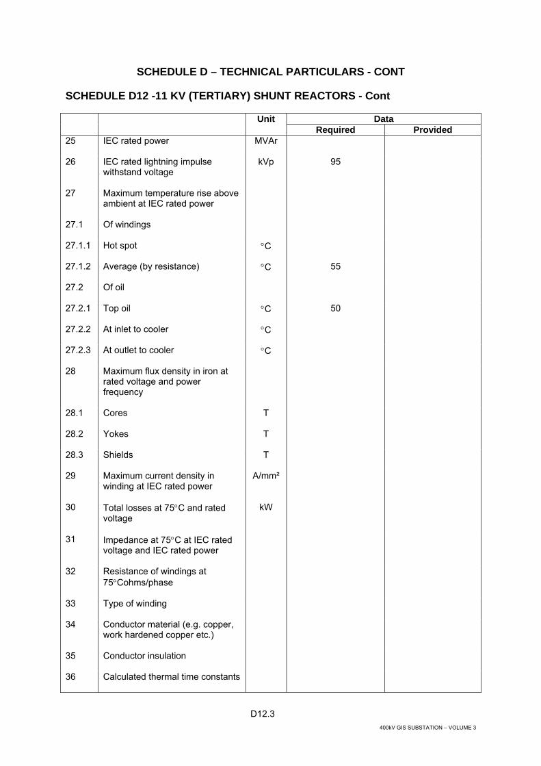
D12.3 400kV GIS SUBSTATION – VOLUME 3
SCHEDULE D – TECHNICAL PARTICULARS - CONT
SCHEDULE D12 -11 KV (TERTIARY) SHUNT REACTORS - Cont
Unit Data Required Provided 25 IEC rated power
MVAr
26 IEC rated lightning impulse withstand voltage
kVp 95
27 Maximum temperature rise above ambient at IEC rated power
27.1 Of windings
27.1.1
Hot spot °C
27.1.2 Average (by resistance)
°C 55
27.2 Of oil
27.2.1 Top oil
°C 50
27.2.2 At inlet to cooler
°C
27.2.3 At outlet to cooler
°C
28 Maximum flux density in iron at rated voltage and power frequency
28.1 Cores
T
28.2 Yokes
T
28.3 Shields
T
29 Maximum current density in winding at IEC rated power
A/mm²
30 Total losses at 75°C and rated voltage
kW
31 Impedance at 75°C at IEC rated voltage and IEC rated power
32 Resistance of windings at 75°Cohms/phase
33 Type of winding
34 Conductor material (e.g. copper, work hardened copper etc.)
35 Conductor insulation
36 Calculated thermal time constants

D12.4 400kV GIS SUBSTATION – VOLUME 3
SCHEDULE D – TECHNICAL PARTICULARS - CONT
SCHEDULE D12 -11 KV (TERTIARY) SHUNT REACTORS - Cont
Unit Data Required Provided 37 Type of joint in magnetic core
(90° butt, overlap, mitre etc.)
37.1 Whether tank or other flux shields are incorporated
37.2 Type of core steel
37.3 Specific loss of core steel at 1.5 tesla
W/kg
38 Voltage rating of neutral bushing or cable box
kV
39 Minimum thickness of tank base
Base Plate
Side Plate
Base Plate
Side Plate
39.1 With flat base
19 6
39.2 Length not exceeding 2500 mm
19 6
Length exceeding 2500 mm not exceeding 7500 mm
25 9
Length exceeding 2500 mm
32 16
With fabricated underbase
Length not exceeding 2500 mm
9 6
Length exceeding 2500 mm
12 9
39.3 Top
mm
40 Material of reactor tank
41 Rating of each cooler or cooler bank
kW
42 Total oil required (including cooling system) litres
43 Total mass of compelte reactor including control gear, all fittings and oil
Tonnes
44 Mass of reactor as arranged for transport (heaviest part)
Tonnes
45 Maximum noise level (‘A’ weighting)
dB
46 Dimensions of reactor arranged for transport

D12.5 400kV GIS SUBSTATION – VOLUME 3
SCHEDULE D – TECHNICAL PARTICULARS - CONT
SCHEDULE D12 -11 KV (TERTIARY) SHUNT REACTORS - Cont
Unit Data Required Provided 46.1 Height
m
46.2 Width
m
46.3 Length
m
47 Departure from linearity of voltage/current characteristic at following percentages of rated voltage
47.1 110 per cent
A
47.2 120 per cent
A
47.3 130 per cent
A
47.4 Whether above values will be demonstrated by test

D13.1 400kV GIS SUBSTATION – VOLUME 3
SCHEDULE D – TECHNICAL PARTICULARS - CONT
SCHEDULE D13 – BUSHINGS
Item No.
Description Unit Required Offered
1 Nominal voltage (UN)
kV 380 132 11
2 Site altitude above sea level for which bushings are to be suitable where this exceeds 1000 m
Less than 1000 m
3 Minimum nominal specific creepage distance in mm per unit of system highest voltage
mm/kV 31
4 Impulse withstand level (full wave 1.2/50 microsecond) under site conditions
kVp 1425 650 95
5 Switching surge withstand level
kVp 1050 - -
6 Arcing horns or rings
Yes Where Oil/Air Bushings provided
7 Radio influence voltage measured at 110 per cent of the maximum line to ground operating voltage and at 1000 kHz, shall be less than
µV 500
8 Maximum symmetrical fault current
kA 40 40 50

D14.1 400kV GIS SUBSTATION – VOLUME 3
SCHEDULE D – TECHNICAL PARTICULARS - CONT
SCHEDULE D14 – LVAC SWITCHGEAR
Data Unit Required Offered
A LVAC SWITCHGEAR (380/220 V, 50 Hz)
1 GENERAL
1.1 Rated voltage
V 380
1.2 Rated frequency
Hz 50
2 LVAC SWITCHBOARD
2.1 Manufacturer
2.2 Type designation
2.3 Type of switchboard Metal-clad withdrawable type,
multi-tier
2.4 Standards
IEC 60439
2.5 Number of years equipment of identical design has been in service
2.6 Rated current of busbars at 50°C ambient temperature
A
2.7 Busbar cross section
mm2
2.8 Busbar insulation material
2.9 Busbar insulation maximum working temperature
°C
210 Temperature rise on continuous operation at rated current at 50°C
2.11 Rated short-time withstand current (1 s)
kA
2.12 Rated peak withstand current
kA
2.13 Test voltage (1 min)
V 2500
2.14 Impulse Withstand Voltage
kVp
2.15 Type of internal barriers, shutters, etc.
Metallic
2.16 Degree of protection
IP51

D14.2 400kV GIS SUBSTATION – VOLUME 3
SCHEDULE D – TECHNICAL PARTICULARS - CONT
SCHEDULE D14 – LVAC SWITCHGEAR - Cont
Data Unit Required Offered
2.17 Overall dimensions per cubicle
− Width mm − Depth mm − Height mm − Weight
kg
2.18 Method of circuit breaker withdrawal
manual
3 CIRCUIT BREAKER
3.1 Manufacturer
3.2 Type designation
3.3 Type
Air, withdrawable
3.4 Number of poles
3
3.5 Standard
IEC 60947-2
3.6 Rated current at 50°C
A
3.7 Rated short-time withstand current (1 s)
kA
3.8 Rated peak withstand current
kA
3.9 Rated symmetrical breaking current
kA
3.10 Rated making current
kA
3.11 Breaking time
s
3.12 Material of:
− moving contacts − fixed contacts
3.13 Design of:
− moving contacts − fixed contacts
3.14 Operating mechanism
− Motor rated power W − Motor operating voltage
V
3.15 Weight of draw-out unit
kg
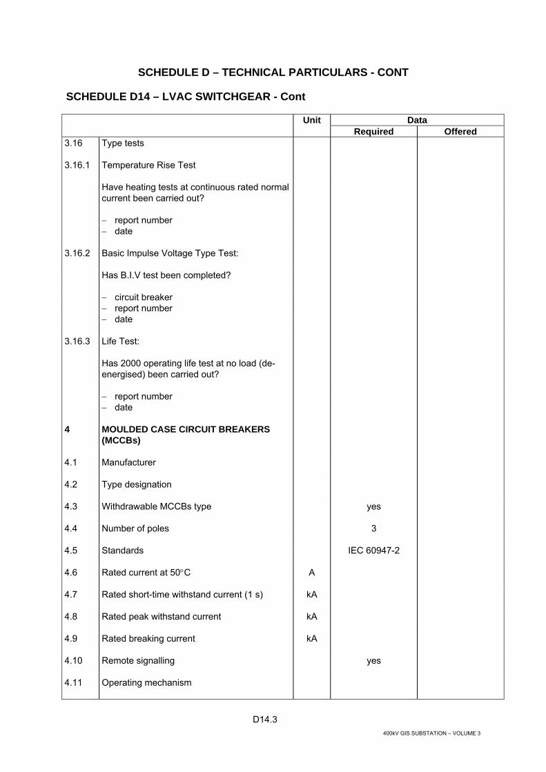
D14.3 400kV GIS SUBSTATION – VOLUME 3
SCHEDULE D – TECHNICAL PARTICULARS - CONT
SCHEDULE D14 – LVAC SWITCHGEAR - Cont
Data Unit Required Offered
3.16 Type tests
3.16.1 Temperature Rise Test
Have heating tests at continuous rated normal current been carried out?
− report number − date
3.16.2 Basic Impulse Voltage Type Test:
Has B.I.V test been completed?
− circuit breaker − report number
− date
3.16.3 Life Test:
Has 2000 operating life test at no load (de-energised) been carried out?
− report number − date
4 MOULDED CASE CIRCUIT BREAKERS (MCCBs)
4.1 Manufacturer
4.2 Type designation
4.3 Withdrawable MCCBs type
yes
4.4 Number of poles
3
4.5 Standards
IEC 60947-2
4.6 Rated current at 50°C
A
4.7 Rated short-time withstand current (1 s)
kA
4.8 Rated peak withstand current
kA
4.9 Rated breaking current
kA
4.10 Remote signalling
yes
4.11 Operating mechanism

D14.4 400kV GIS SUBSTATION – VOLUME 3
SCHEDULE D – TECHNICAL PARTICULARS - CONT
SCHEDULE D14 – LVAC SWITCHGEAR - Cont
Data Unit Required Offered
4.12 Mass
5 CURRENT TRANSFORMERS 5.1 Manufacturer
5.2 Type 5.3 Type of primary winding (e.g. bar, wound,
etc.)
5.4 Standards IEC 60044-1 5.5 Rated voltage
kV
5.6 Rated lightning impulse withstand voltage phase to earth
kV
5.7 Rated power frequency withstand voltage phase to earth
kV
5.8 Partial discharge test voltage kV 5.9 Rated frequency
Hz 50
5.10 Rated continuous thermal current at 50oC
5.11 Rated short-time withstand current (1 s)
kA
5.12 Rated dynamic current
kA
5.13 Line current transformer
5.13.1 Type designation
5.13.2 Number of cores
5.13.3 Rated extended primary current
%
5.13.4 Ratio (TR = turns ratio) • I core • II core
A A
5.13.5 Class • I core • II core
5.13.6 Knee point voltage (EK) • I core • II core
V V

D14.5 400kV GIS SUBSTATION – VOLUME 3
SCHEDULE D – TECHNICAL PARTICULARS - CONT
SCHEDULE D14 – LVAC SWITCHGEAR - Cont
Data Unit Required Offered
5.13.7 Exciting current (IE) at EK • I core • II core
A A
5.13.8 Rated output (burden to be 25-100% rated burden) • I core • II core
VA VA
6 INSTRUMENTS
6.1 Manufacturer
6.2 Standards
IEC 60051
6.3 Type designation − Ammeter
− Voltmeter
6.4 Total scale range − Ammeter − Voltmeter
6.5 Dimensions
mm
6.6 Accuracy
7 PROTECTION RELAYS
7.1 Earth Fault Protection
7.1.1 Manufacturer
7.1.2 Type reference
7.1.3 Relay design (electromechanical, static, microprocessor-based, numerical)
7.1.4 Range of current settings, percent of current rating
%
7.1.5 Range of time multiplier setting
7.1.6 Current at which relay resets, percent of current setting
%
7.1.7 Current at which relay picks-up, percent of current setting
%

D14.6 400kV GIS SUBSTATION – VOLUME 3
SCHEDULE D – TECHNICAL PARTICULARS - CONT
SCHEDULE D14 – LVAC SWITCHGEAR - Cont
Data Unit Required Offered
7.1.8 Self-checking facility
7.1.9 CT’s requirements
7.1.10 Tripping contacts ratings
7.2 Restricted Earth Fault Protection
7.2.1 Manufacturer
7.2.2 Type reference
7.2.3 Relay design (electromechanical, static, microprocessor-based, numerical)
7.2.4 Estimated minimum faults setting (% of CT rating)
%
7.2.5 Operating time at 5 x setting
ms
7.2.6 Maximum primary out-of-zone fault current at which protection is stable
A
7.2.7 State principle of operation, i.e. H - high impedance L - low impedance
H
7.2.8 Current transformer requirements: − Required knee point voltage, Vk − CT maximum winding resistance − Magnetising current at Vk
V Ω A
7.2.9 Self monitoring
yes
7.2.10 Self checking
yes
7.2.11 Tripping contacts rating
7.3 Undervoltage / Overvoltage Relay
7.3.1 Manufacturer
7.3.2 Type reference
7.3.3 Relay design (electromechanical, static)
7.3.4 Total scale range
V
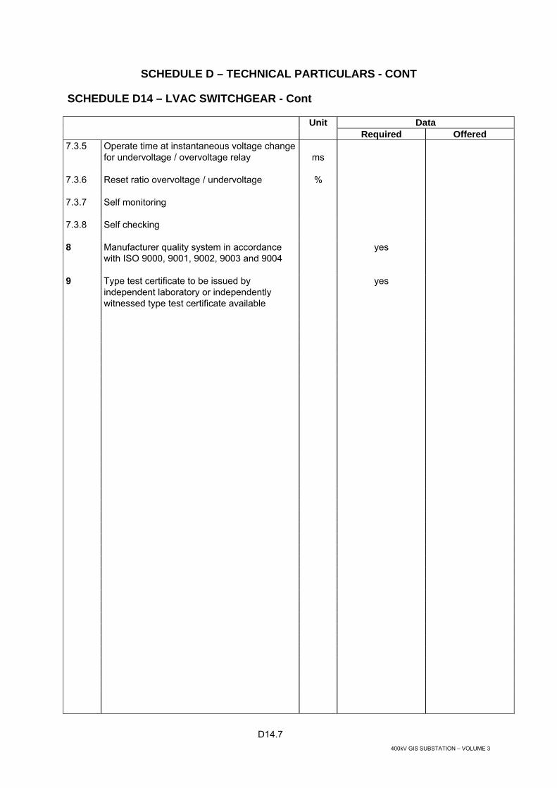
D14.7 400kV GIS SUBSTATION – VOLUME 3
SCHEDULE D – TECHNICAL PARTICULARS - CONT
SCHEDULE D14 – LVAC SWITCHGEAR - Cont
Data Unit Required Offered
7.3.5 Operate time at instantaneous voltage change for undervoltage / overvoltage relay
ms
7.3.6 Reset ratio overvoltage / undervoltage
%
7.3.7 Self monitoring
7.3.8 Self checking
8 Manufacturer quality system in accordance with ISO 9000, 9001, 9002, 9003 and 9004
yes
9 Type test certificate to be issued by independent laboratory or independently witnessed type test certificate available
yes

D15.1 400kV GIS SUBSTATION – VOLUME 3
SCHEDULE D – TECHNICAL PARTICULARS - CONT
SCHEDULE D15– DC SYSTEM
Data 110 V D.C System Unit Required Offered
1 110 V D.C SYSTEM - SUBSTATION SERVICES SUPPLY
1.1 110 V Battery Units
1.1.1 Manufacturer
1.1.2 Type designation
1.1.3 Number of battery units
2
1.1.4 Type of cell
Nickel-Cadmium
1.1.5 Operating voltage per cell
V
1.1.6 Number of cells
1.1.7 Standard * IEEE 1115 for calculation
* IEC 60623, 60478, 60439 for
equipment
1.1.8 Discharge capacity:
− 10 hour rate Ah min. 250 (to be confirmed by calculation)
− 5 hour rate Ah − 3 hour rate Ah − 1 hour rate Ah − 30 minute rate
Ah
1.1.9 Final cell voltage after discharge:
− 10 hour rate V − 5 hour rate V − 3 hour rate V − 1 hour rate V − 30 minute rate
V
1.1.10 Ampere hour efficiency:
− 10 hour rate % − 5 hour rate % − 3 hour rate % − 1 hour rate % 1.1.11 Watt hour efficiency:
− 10 hour rate % − 5 hour rate % − 3 hour rate %

D15.2 400kV GIS SUBSTATION – VOLUME 3
SCHEDULE D – TECHNICAL PARTICULARS - CONT
SCHEDULE D15 – DC SYSTEM - Cont
Data 110 V D.C System Unit Required Offered
− 1 hour rate % − 30 minute rate
%
1.1.12 Maximum charging voltage per cell
V
1.1.13 Normal charging rate range
A
1.1.14 Maximum charging rate range
A
1.1.15 Float charging rate
A
1.1.16 Boost charging rate
A
1.1.17 Normal voltage across battery on float charge
V
1.1.18 Voltage per cell on float charge
V
1.1.19 Normal voltage across battery on boost charge
V
1.1.20 Voltage per cell on boost charge
V
1.1.21 Overall dimensions of one cell
mm
1.1.22 Quantity of electrolyte per cell
Litres
1.1.23 Overall dimensions of each stand
mm
1.1.24 Number of stands
1.1.25 Number of tiers
1.1.26 Material and cross section of connections: − between cells − between tiers − between stands − to battery fuse box
mm2 mm2
mm2 mm2
1.1.27 Method of treating copper connection against corrosion
1.1.28 Method of protecting copper connections against accidental short circuiting
1.1.29 Estimated short circuit current from fully charged battery
A
1.1.30 Anticipated life of electrolyte under actual operating conditions
Years

D15.3 400kV GIS SUBSTATION – VOLUME 3
SCHEDULE D – TECHNICAL PARTICULARS - CONT
SCHEDULE D15 – DC SYSTEM - Cont
Data 110 V D.C System Unit Required Offered
1.1.31 Anticipated life of electrolyte under actual operating conditions
Years
1.1.32 Operating temperatures: - Normal operation - maximum - minimum
°C °C
- Emergency discharge - maximum - minimum
°C °C
1.2 110 V D.C Battery Chargers
1.2.1 Manufacturer
1.2.2 Type designation
1.2.3 Degree of protection
IP 51
1.2.4 Number of chargers
2 x 100% for each battery
1.2.5 Type
1.2.6 Charging characteristic
1.2.7 Input voltage
V 3 Phase, 380
1.2.8 Input frequency and range
Hz 50 ± 5%
1.2.9 Input power
kVA
1.2.10 Minimum working power factor
1.2.11 Overload range
%
1.2.12 Voltage ripple
%
1.2.13 Ripple frequency
Hz
1.2.14 Means of adjusting output
1.2.15 Details of any forced cooling equipment for chargers
1.2.16 Ambient temperature range
°C
1.2.17 Ambient relative humidity range
%
1.2.18 Mean time between failure (MTBF)
Years

D15.4 400kV GIS SUBSTATION – VOLUME 3
SCHEDULE D – TECHNICAL PARTICULARS - CONT
SCHEDULE D15 – DC SYSTEM - Cont
Data 110 V D.C System Unit Required Offered
1.2.19 Overall dimensions (shall be a separate free-standing panel/cubicle)
mm
1.2.20 Weight
kg
1.2.21 Boost charge maximum permitted constant potential per cell
V
1.2.22 Boost charge maximum permitted current as percentage of 5 hour capacity
%
1.2.23 Time to be re-charge to 90% capacity at maximum permitted voltage and current
hrs
1.3 Battery Fuse Boxes
1.3.1 Manufacturer
1.3.2 Type designation
1.3.3 Degree of protection
IP 51
1.3.4 Fuse rated current at 50oC
1.3.5 Remote signalling
yes
1.4 110 V D.C. Switchboards
1.4.1 Manufacturer
1.4.2 Type designation
1.4.3 Degree of protection
IP 51
1.4.4 Standards
IEC 60439
1.4.5 Rating voltage
V 110
1.4.6 Rated current of busbars at 50oC ambient temperature
A
1.4.7 Busbar cross section
mm2
1.4.8 Busbar insulation material
1.4.9 Number of circuits
1.4.10 Main isolator rating
A
1.4.11 Main fuse rating
A
1.4.12 Single line diagram number

D15.5 400kV GIS SUBSTATION – VOLUME 3
SCHEDULE D – TECHNICAL PARTICULARS - CONT
SCHEDULE D15 – DC SYSTEM - Cont
Data 110 V D.C System Unit Required Offered
Arrangement drawing number
1.4.13 Details of Contactors:
− Manufacturer − Type designation − Type − Site current rating (at 50°C) A − Rated breaking capacity kA − Short time current (1 s) kA − Maximum operating time
• opening msec • closing
msec
− Voltage / power coil rating V/W − Typical circuit diagram number
1.4.14 Details of Earth Fault Protection:
− Manufacturer − Type Designation − Brochure number
1.4.15 Details of Undervoltage / Overvoltage Protection:
− Manufacturer − Type Designation − Brochure number
1.4.16 Instruments
− Manufacturer − Voltmeter (type) − Ammeter (type) − Instruments
Details of Moulded Case Circuit Breakers (MCCBs)
- Manufacturer - Type designation - Number of poles A - Standards kA - Rated current at 50°C kA Yes - Rated short-time withstand current
(1s)
- Rated breaking capacity - Remote signalling

D15.6 400kV GIS SUBSTATION – VOLUME 3
SCHEDULE D – TECHNICAL PARTICULARS - CONT
SCHEDULE D15 – DC SYSTEM - Cont
Data 110 V D.C System Unit Required Offered
1.4.17 Details of Miniature Circuit Breakers (MCBs)
− Manufacturer − Type designation − Number of poles − Standards A Yes − Rated current at 50°C kA − Rated short-time withstand current
(1s) kA
− Breaking capacity at − Remote signalling
Manufacturer quality system in accordance with ISO 9000, 9001, 9002, 9003 and 9004
Yes
Type test certificate to be issued by independent laboratory or independently witnessed type test certificate available
Yes

D15.7 400kV GIS SUBSTATION – VOLUME 3
SCHEDULE D – TECHNICAL PARTICULARS - CONT
SCHEDULE D15 – DC SYSTEM
Data 48 V D.C System Unit Required Offered
1 48 V D.C SYSTEM - SUBSTATION SERVICES SUPPLY
1.1 48 V Battery Units
1.1.1 Manufacturer
1.1.2 Type designation
1.1.3 Number of battery units
2
1.1.4 Type of cell
Nickel-Cadmium
1.1.5 Operating voltage per cell
V
1.1.6 Number of cells
1.1.7 Standard * IEEE 1115 for calculation
* IEC 60623, 60478, 60439 for
equipment
1.1.8 Discharge capacity:
− 10 hour rate Ah min. 250 (to be confirmed by calculation)
− 5 hour rate Ah − 3 hour rate Ah − 1 hour rate Ah − 30 minute rate
Ah
1.1.9 Final cell voltage after discharge:
− 10 hour rate V − 5 hour rate V − 3 hour rate V − 1 hour rate V − 30 minute rate
V
1.1.10 Ampere hour efficiency:
− 10 hour rate % − 5 hour rate % − 3 hour rate % − 1 hour rate
%
1.1.11 Watt hour efficiency:
− 10 hour rate % − 5 hour rate % − 3 hour rate %

D15.8 400kV GIS SUBSTATION – VOLUME 3
SCHEDULE D – TECHNICAL PARTICULARS - CONT
SCHEDULE D15 – DC SYSTEM - Cont
Data 48 V D.C System Unit Required Offered
− 1 hour rate % − 30 minute rate
%
1.1.12 Maximum charging voltage per cell
V
1.1.13 Normal charging rate range
A
1.1.14 Maximum charging rate range
A
1.1.15 Float charging rate
A
1.1.16 Boost charging rate
A
1.1.17 Normal voltage across battery on float charge
V
1.1.18 Voltage per cell on float charge
V
1.1.19 Normal voltage across battery on boost charge
V
1.1.20 Voltage per cell on boost charge
V
1.1.21 Overall dimensions of one cell
mm
1.1.22 Quantity of electrolyte per cell
Litres
1.1.23 Overall dimensions of each stand
mm
1.1.24 Number of stands
1.1.25 Number of tiers
1.1.26 Material and cross section of connections: − between cells − between tiers − between stands − to battery fuse box
mm2 mm2
mm2 mm2
1.1.27 Method of treating copper connection against corrosion
1.1.28 Method of protecting copper connections against accidental short circuiting
1.1.29 Estimated short circuit current from fully charged battery
A
1.1.30 Anticipated life of electrolyte under actual operating conditions
Years
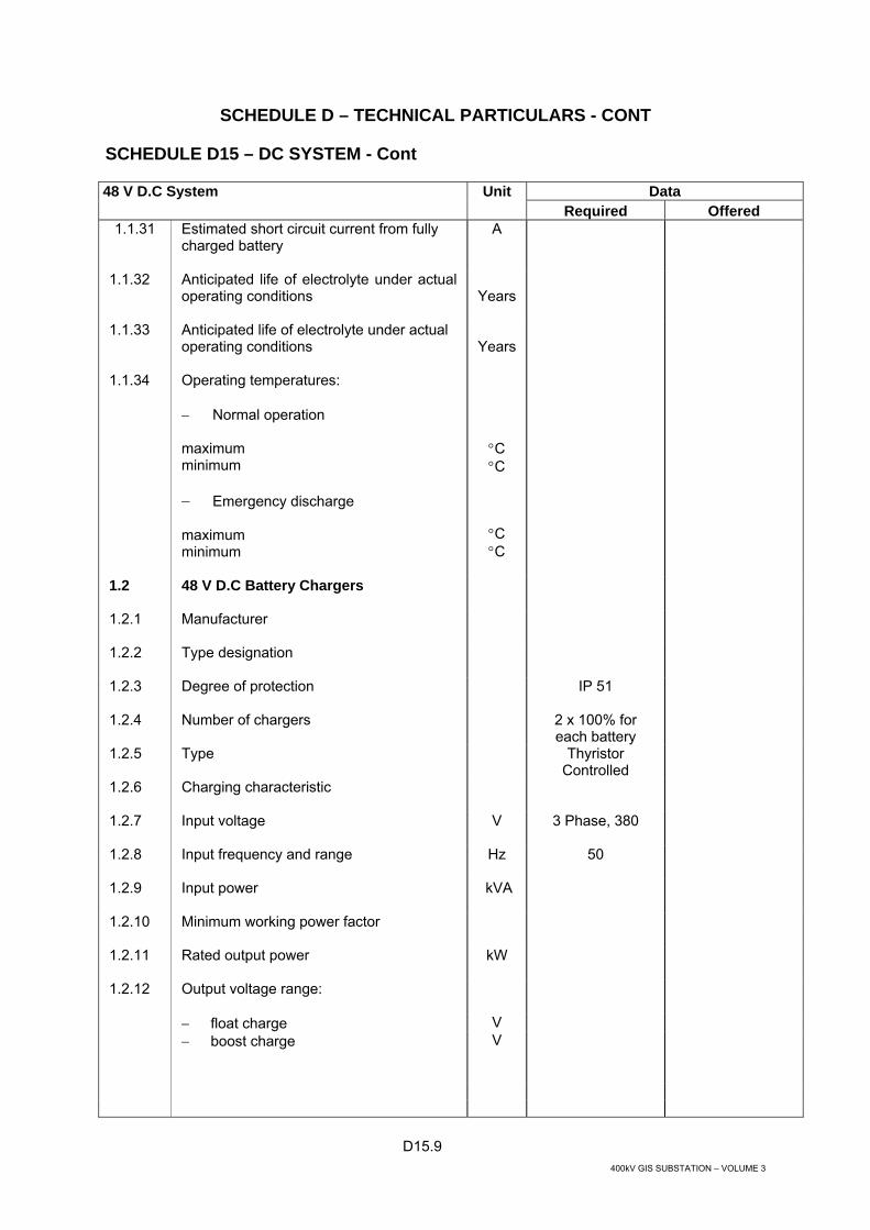
D15.9 400kV GIS SUBSTATION – VOLUME 3
SCHEDULE D – TECHNICAL PARTICULARS - CONT
SCHEDULE D15 – DC SYSTEM - Cont
Data 48 V D.C System Unit Required Offered
1.1.31 Estimated short circuit current from fully charged battery
A
1.1.32 Anticipated life of electrolyte under actual operating conditions
Years
1.1.33 Anticipated life of electrolyte under actual operating conditions
Years
1.1.34 Operating temperatures: − Normal operation maximum minimum
°C °C
− Emergency discharge maximum minimum
°C °C
1.2 48 V D.C Battery Chargers
1.2.1 Manufacturer
1.2.2 Type designation
1.2.3 Degree of protection
IP 51
1.2.4 Number of chargers
2 x 100% for each battery
1.2.5 Type
Thyristor Controlled
1.2.6 Charging characteristic
1.2.7 Input voltage
V 3 Phase, 380
1.2.8 Input frequency and range
Hz 50
1.2.9 Input power
kVA
1.2.10 Minimum working power factor
1.2.11 Rated output power
kW
1.2.12 Output voltage range:
− float charge V − boost charge
V

D15.10 400kV GIS SUBSTATION – VOLUME 3
SCHEDULE D – TECHNICAL PARTICULARS - CONT
SCHEDULE D15 – DC SYSTEM - Cont
Data 48 V D.C System Unit Required Offered
1.2.13 Continuous output current range:
− float charge A − boost charge
A
Accuracy of output voltage
%
1.2.14 Overload range
%
1.2.15 Voltage ripple
%
1.2.16 Ripple frequency
Hz
1.2.17 Means of adjusting output
1.2.18 Details of any forced cooling equipment for chargers
1.2.19 Ambient temperature range
°C
1.2.20 Ambient relative humidity range
%
1.2.21 Mean time between failure (MTBF)
Years
1.2.22 Overall dimensions (shall be a separate free-standing panel/cubicle)
mm
1.2.23 Weight
kg
1.2.24 Boost charge maximum permitted constant potential per cell
V
1.2.25 Boost charge maximum permitted current as percentage of 5 hour capacity
%
1.2.26 Time to be re-charge to 90% capacity at maximum permitted voltage and current
hrs
1.3 Battery Fuse Boxes
1.3.1 Manufacturer
1.3.2 Type designation
1.3.3 Degree of protection
IP 51
1.3.4 Fuse rated current at 50oC
1.3.5 Remote signalling
yes
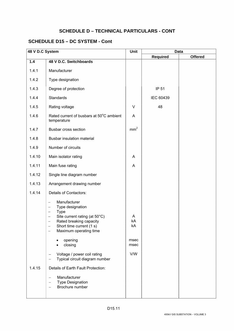
D15.11 400kV GIS SUBSTATION – VOLUME 3
SCHEDULE D – TECHNICAL PARTICULARS - CONT
SCHEDULE D15 – DC SYSTEM - Cont
Data 48 V D.C System Unit Required Offered
1.4 48 V D.C. Switchboards
1.4.1 Manufacturer
1.4.2 Type designation
1.4.3 Degree of protection
IP 51
1.4.4 Standards
IEC 60439
1.4.5 Rating voltage
V 48
1.4.6 Rated current of busbars at 50oC ambient temperature
A
1.4.7 Busbar cross section
mm2
1.4.8 Busbar insulation material
1.4.9 Number of circuits
1.4.10 Main isolator rating
A
1.4.11 Main fuse rating
A
1.4.12 Single line diagram number
1.4.13 Arrangement drawing number
1.4.14 Details of Contactors:
− Manufacturer − Type designation − Type − Site current rating (at 50°C) A − Rated breaking capacity kA − Short time current (1 s) kA − Maximum operating time
• opening msec • closing
msec
− Voltage / power coil rating V/W − Typical circuit diagram number
1.4.15 Details of Earth Fault Protection:
− Manufacturer − Type Designation − Brochure number
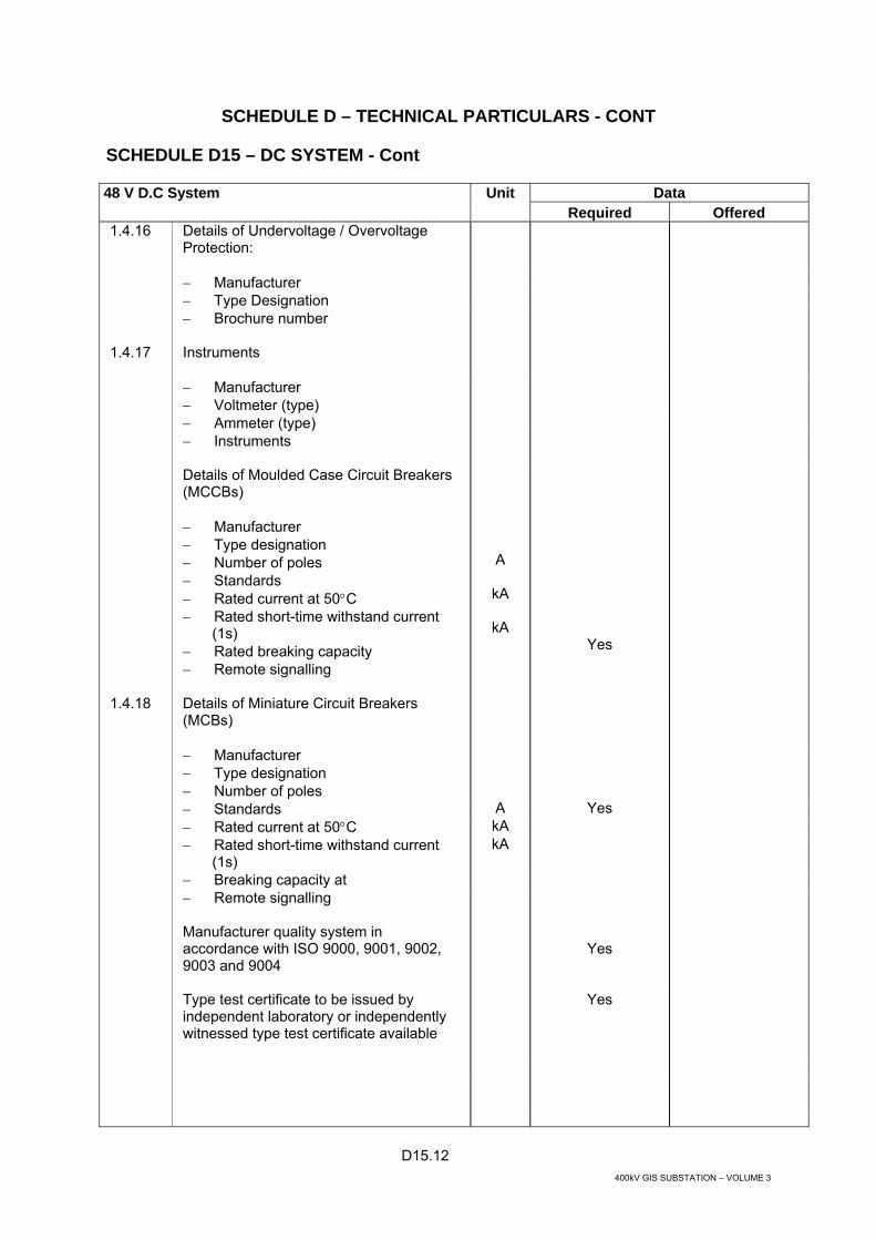
D15.12 400kV GIS SUBSTATION – VOLUME 3
SCHEDULE D – TECHNICAL PARTICULARS - CONT
SCHEDULE D15 – DC SYSTEM - Cont
Data 48 V D.C System Unit Required Offered
1.4.16 Details of Undervoltage / Overvoltage Protection:
− Manufacturer − Type Designation − Brochure number
1.4.17 Instruments
− Manufacturer − Voltmeter (type) − Ammeter (type) − Instruments
Details of Moulded Case Circuit Breakers (MCCBs) − Manufacturer − Type designation − Number of poles − Standards − Rated current at 50°C − Rated short-time withstand current
(1s) − Rated breaking capacity − Remote signalling
A
kA
kA
Yes
1.4.18 Details of Miniature Circuit Breakers (MCBs)
− Manufacturer − Type designation − Number of poles − Standards A Yes − Rated current at 50°C kA − Rated short-time withstand current
(1s) kA
− Breaking capacity at − Remote signalling
Manufacturer quality system in accordance with ISO 9000, 9001, 9002, 9003 and 9004
Yes
Type test certificate to be issued by independent laboratory or independently witnessed type test certificate available
Yes

D16.1 400kV GIS SUBSTATION – VOLUME 3
SCHEDULE D – TECHNICAL PARTICULARS - CONT
SCHEDULE D16 - 220 V AC UNINTERRUPTIBLE POWER SUPPLY
Data
Unit Required Offered
1 GENERAL
The uninterruptible power supply (UPS) shall consist but not be limited to the following items:
− 48 V DC / 220 V AC inverters
yes
− static interrupters and transfer switches
yes
− 220/220 V single phase isolating by-pass transformer
yes
− manual by-pass switch
yes
− UPS distribution board yes
2 INVERTER
2.1 Manufacturer
2.2 Type designation
2.3 Degree of protection
IP51
2.4 Rated output power VA min 1200 (to be confirmed by calculation)
2.5 Rated input voltage and range
V±%
2.6 Rated input current
A
2.7 Rated output voltage
V
2.8 Steady state voltage variation
%
2.9 Rated output current
A
2.10 Rated output frequency
Hz
2.11 Steady state frequency variation
%
2.12 Total harmonic distortion
%
2.13 Rated output power factor
2.14 Maximum harmonic distortion:
− at any single frequency % − at all frequencies %

D16.2 400kV GIS SUBSTATION – VOLUME 3
SCHEDULE D – TECHNICAL PARTICULARS - CONT
SCHEDULE D16 - 220 V AC UNINTERRUPTIBLE POWER SUPPLY - Cont
Data
Unit Required Offered
2.15 Radio frequency interference (RFI) classification
2.16 Output voltage rise time on turn-on
ms
2.17 Output voltage decay time on turn-off
ms
2.18 Maximum transient voltage variation after full load acceptance or rejection for:
− 1 cycle % − 0.1 s % − 1 s
%
2.19 Method of cooling
2.20 Ambient temperature range
°C
2.21 Maximum temperature rise (inside)
°C
2.22 Ambient relative humidity
%
2.23 Method of protecting inverters against high intensity D.C voltage surges
2.24 Mean time between failure (MTBF)
Years
2.25 Dimensions
mm
2.26 Weight
kg
3 STATIC SWITCH
A detailed description of offered static switch with data and diagram to be provided
4 ISOLATION BY-PASS TRANSFORMER
4.1 Manufacturer
4.2 Standard applied
4.3 Type designation
4.4 Maximum continuous capacity
VA
4.5 Number of phase
1
4.6 Rated voltage under full load
V

D16.3 400kV GIS SUBSTATION – VOLUME 3
SCHEDULE D – TECHNICAL PARTICULARS - CONT
SCHEDULE D16 - 220 V AC UNINTERRUPTIBLE POWER SUPPLY - Cont
Data
Unit Required Offered
4.7 Protection class
IP
Dimensions overall
mm
Total weight kg 5 MANUAL BY-PASS SWITCH
5.1 Manufacturer
5.2 Type of designation
5.3 Rated current at 50°C
A
6 DISTRIBUTION BOARD
6.1 Manufacturer
6.2 Type designation
6.3 Degree of protection
IP 51
6.4 Busbar insulation material
6.5 Number of circuits
6.6 Details of Miniature Circuit Breakers (MCBs)
− Manufacturer − Type designation − Number of poles − Standards
− Rated current at 50oC A − Rated breaking capacity kA − Remote signalling
Manufacturer quality system in accordance with ISO 9000, 9001, 9002, 9003 and 9004
yes
Type test certificate to be issued by independent laboratory or independently witnessed type test certificate available
yes

D17.1 400kV GIS SUBSTATION – VOLUME 3
SCHEDULE D – TECHNICAL PARTICULARS - CONT
SCHEDULE D17 – 132/11 KV POWER CABLES
132 kV Power Cables Unit Data Required Offered 1 GENERAL
1.1 Name of manufacturer
1.2 Place of manufacture
1.3 Manufacturers type or drawing reference number
1.4 Circuit rating required
MVA
1.5 Constructional and Testing standards
Standard(s) to which cable complies 1.6 General description of cable
Voltage designation Uo/U(Um) kV Number of cores one Conductor size mm2 Conductor material aluminium Type of insulation XLPE Type of metal screen/sheath lead Type of armour Type of oversheath
MDPE
1.7 Year of first commercial operation of cable type 2 CONSTRUCTIONAL FEATURES
2.1 Conductor
Material aluminium Nominal cross-section mm2 Type of conductor Overall diameter mm Water blocking method Semi conducting binder tape yes/no 2.2 Conductor screen
Type of material Extruded semi conductive,
cross-linkable, fully bonded
Nominal thickness mm 2.3 Insulation
Material XLPE Thickness: Minimum average mm Thickness: Minimum at a point mm Nominal overall diameter mm

D17.2 400kV GIS SUBSTATION – VOLUME 3
SCHEDULE D – TECHNICAL PARTICULARS - CONT
SCHEDULE D17 – 132/11 KV POWER CABLES - Cont
132 kV Power Cables Unit Data Required Offered 2.4 Insulation screen
Type of material Extruded semi conductive,
cross-linkable
Nominal thickness mm 2.5 XLPE Manufacturing Methods
- Extrusion line type e.g. CCV - Single pass, triple extrusion yes/no - Curing method - Cooling method 2.6 Bedding (if applicable)
Type and material 2.7 Metallic screen on each core
Type and material copper wire or tape
Nominal thickness mm Nominal diameter over the screen mm 2.8 Bedding layer
Type and material Nominal thickness mm Minimum thickness mm 2.9 Armour
Nominal diameter under the armour mm Type and material Armour wire diameter or dimensions of strip mm 2.10 Protective anti-corrosion external sheath covering
Type and material MDPE Colour Nominal thickness mm Minimum thickness mm Termite resistant yes/no yes Type of anti-termite protection 2.11 Nominal overall cable diameter mm 2.12 Weight of completed cable kg/m

D17.3 400kV GIS SUBSTATION – VOLUME 3
SCHEDULE D – TECHNICAL PARTICULARS - CONT
SCHEDULE D17 – 132/11 KV POWER CABLES - Cont
132 kV Power Cables Unit Data Required Offered 3 CURRENT RATINGS
3.1 Maximum continuous rating, direct-buried, assuming:
Ground temperature at burial depth of 35oC Soil thermal resistivity of 2.5K.m/W Depth of laying 0.8m Thermally independent of other cable circuits trefoil touching (solid bonded) A flat formation spaced at one cable diameter (single
point bonded) A
Calculation Method
IEC 60287
3.2 Maximum continuous rating, in single way ducts, assuming:
Ground temperature at burial depth of 35oC Soil thermal resistivity of 2.5K.m/W Depth of laying 0.8m Thermally independent of other cable circuits trefoil touching (solid bonded) A flat touching formation (single point bonded) A Calculation Method
IEC 60287
3.3 Maximum continuous rating, in-air, assuming:
Air temperature (in shade) of 50 oC Thermally independent of other cable circuits trefoil touching (solid bonded) A flat formation spaced at one cable diameter (single
point bonded) A
Calculation Method
IEC 60287
3.4 Maximum permissible conductor temperature for continuous operation
oC
3.5 Conductor short circuit capacity
Short circuit current kA 40 Duration s 3 Permissible maximum temperature
oC 250
3.6 Screen / armour short circuit capacity
Short circuit current kA Duration s 3 Permissible maximum temperature oC 200 4 ELECTRICAL CHARACTERISTICS
4.1 DC resistance of conductor at 20˚C Ω/m

D17.4 400kV GIS SUBSTATION – VOLUME 3
SCHEDULE D – TECHNICAL PARTICULARS - CONT
SCHEDULE D17 – 132/11 KV POWER CABLES - Cont
132 kV Power Cables Unit Data Required Offered 4.2 AC resistance of conductor at 50 Hz and maximum
conductor temperature
Ω/m
trefoil touching (solid bonded) Ω/m flat formation (single point bonded)
Ω/m
4.3 Positive Sequence Resistance of cable at 50 Hz
Ω/m
trefoil touching (solid bonded) Ω/m flat formation (single point bonded)
Ω/m
4.4 Positive Sequence Reactance of cable at 50 Hz
Ω/m
trefoil touching (solid bonded) Ω/m flat formation (single point bonded)
Ω/m
4.5 Zero Sequence Resistance of cable at 50 Hz in trefoil touching formation (solid bonded)
Ω/m
4.6 Zero Sequence Reactance of cable at 50 Hz in trefoil touching formation (solid bonded)
Ω/m
4.7 Capacitance per core pF/m 5 LOSSES
5.1 Total losses per three phase circuit when operating at nominal voltage and 50Hz and at the current ratings stated in Item 2 :
W/m
laid direct in trefoil touching (solid bonded) W/m laid direct in flat formation (single point bonded)
W/m
in ducts in trefoil touching (solid bonded) W/m in ducts in flat touching formation
single point bonded) W/m
in air in trefoil touching (solid bonded) W/m in air in flat formation (single point bonded)
W/m
6 INSTALLATION DATA
6.1 Minimum cable bending radius when laid:
During installation mm Adjacent to joints and terminations mm 6.2 Minimum internal diameter of pipes or ducts
mm
6.2 Maximum permissible pulling force of total cable
kN

D17.5 400kV GIS SUBSTATION – VOLUME 3
SCHEDULE D – TECHNICAL PARTICULARS - CONT
SCHEDULE D17 – 132/11 KV POWER CABLES - Cont
132 kV Power Cables Unit Data Required Offered 7 COMMISSIONING TESTS
7.1 Recommended tests after all terminating and jointing has been completed but before connection to the system.

D17.6 400kV GIS SUBSTATION – VOLUME 3
SCHEDULE D – TECHNICAL PARTICULARS - CONT
SCHEDULE D17 – 132/11 KV POWER CABLES - Cont
11 kV Power Cables Unit Data Required Offered 1 GENERAL
1.1 Name of manufacturer
1.2 Place of manufacture
1.3 Manufacturers type or drawing reference number
1.4 Circuit rating required
MVA
1.5 Constructional and Testing standards
Standard(s) to which cable complies 1.6 General description of cable
Voltage designation Uo/U(Um) kV Number of cores one Conductor size mm2 Conductor material copper Type of insulation XLPE Type of metal screen/sheath Type of armour Type of oversheath
1.7 Year of first commercial operation of cable type 2 CONSTRUCTIONAL FEATURES
2.1 Conductor
Material Copper Nominal cross-section mm2 Type of conductor Overall diameter mm Water blocking method Semi conducting binder tape yes/no 2.2 Conductor screen
Type of material Extruded semi conductive,
cross-linkable, fully bonded
Nominal thickness mm 2.3 Insulation
Material XLPE Thickness: Minimum average mm Thickness: Minimum at a point mm Nominal overall diameter mm

D17.7 400kV GIS SUBSTATION – VOLUME 3
SCHEDULE D – TECHNICAL PARTICULARS - CONT
SCHEDULE D17 – 132/11 KV POWER CABLES - Cont
11 kV Power Cables Unit Data Required Offered 2.4 Insulation screen
Type of material Extruded semi conductive,
cross-linkable
Nominal thickness mm 2.5 XLPE Manufacturing Methods
- Extrusion line type e.g. CCV - Single pass, triple extrusion yes/no - Curing method - Cooling method 2.6 Bedding (if applicable)
Type and material 2.7 Metallic screen on each core
Type and material copper wire or tape
Nominal thickness mm Nominal diameter over the screen mm 2.8 Bedding layer
Type and material Nominal thickness mm Minimum thickness mm 2.9 Armour
Nominal diameter under the armour mm Type and material Armour wire diameter or dimensions of strip mm 2.10 Protective anti-corrosion external sheath covering
Type and material MDPE Colour Nominal thickness mm Minimum thickness mm Termite resistant yes/no yes Type of anti-termite protection 2.11 Nominal overall cable diameter
mm
2.12 Weight of completed cable
kg/m

D17.8 400kV GIS SUBSTATION – VOLUME 3
SCHEDULE D – TECHNICAL PARTICULARS - CONT
SCHEDULE D17 – 132/11 KV POWER CABLES - Cont
11 kV Power Cables Unit Data Required Offered 3 CURRENT RATINGS
3.1 Maximum continuous rating, direct-buried, assuming:
Ground temperature at burial depth of 35oC Soil thermal resistivity of 2.5K.m/W Depth of laying 0.8m Thermally independent of other cable circuits trefoil touching (solid bonded) A flat formation spaced at one cable diameter (single
point bonded) A
Calculation Method
IEC 60287
3.2 Maximum continuous rating, in single way ducts, assuming:
Ground temperature at burial depth of 35oC Soil thermal resistivity of 2.5K.m/W Depth of laying 0.8m Thermally independent of other cable circuits trefoil touching (solid bonded) A flat touching formation (single point bonded) A Calculation Method
IEC 60287
3.3 Maximum continuous rating, in-air, assuming:
Air temperature (in shade) of 50 oC Thermally independent of other cable circuits trefoil touching (solid bonded) A flat formation spaced at one cable diameter (single
point bonded) A
Calculation Method
IEC 60287
3.4 Maximum permissible conductor temperature for continuous operation
oC
3.5 Conductor short circuit capacity
Short circuit current kA 50 Duration s 1 Permissible maximum temperature
oC 250
3.6 Screen / armour short circuit capacity
Short circuit current kA Duration s 3 Permissible maximum temperature oC 200 4 ELECTRICAL CHARACTERISTICS
4.1 DC resistance of conductor at 20˚C Ω/m

D17.9 400kV GIS SUBSTATION – VOLUME 3
SCHEDULE D – TECHNICAL PARTICULARS - CONT
SCHEDULE D17 – 132/11 KV POWER CABLES - Cont
11 kV Power Cables Unit Data Required Offered 4.2 AC resistance of conductor at 50 Hz and maximum
conductor temperature
Ω/m
trefoil touching (solid bonded) Ω/m flat formation (single point bonded)
Ω/m
4.3 Positive Sequence Resistance of cable at 50 Hz
Ω/m
trefoil touching (solid bonded) Ω/m flat formation (single point bonded)
Ω/m
4.4 Positive Sequence Reactance of cable at 50 Hz
Ω/m
trefoil touching (solid bonded) Ω/m flat formation (single point bonded)
Ω/m
4.5 Zero Sequence Resistance of cable at 50 Hz in trefoil touching formation (solid bonded)
Ω/m
4.6 Zero Sequence Reactance of cable at 50 Hz in trefoil touching formation (solid bonded)
Ω/m
4.7 Capacitance per core pF/m 5 LOSSES
5.1 Total losses per three phase circuit when operating at nominal voltage and 50Hz and at the current ratings stated in Item 2 :
W/m
laid direct in trefoil touching (solid bonded) W/m laid direct in flat formation (single point bonded)
W/m
in ducts in trefoil touching (solid bonded) W/m in ducts in flat touching formation
(single point bonded) W/m
in air in trefoil touching (solid bonded) W/m in air in flat formation (single point bonded)
W/m
6 INSTALLATION DATA
6.1 Minimum cable bending radius when laid:
During installation mm Adjacent to joints and terminations mm 6.2 Minimum internal diameter of pipes or ducts
mm
6.2 Maximum permissible pulling force of total cable
kN

D17.10 400kV GIS SUBSTATION – VOLUME 3
SCHEDULE D – TECHNICAL PARTICULARS - CONT
SCHEDULE D17 – 132/11 KV POWER CABLES - Cont
11 kV Power Cables Unit Data Required Offered 7 COMMISSIONING TESTS
7.4 Recommended tests after all terminating and jointing has been completed but before connection to the system.

D18.1 400kV GIS SUBSTATION – VOLUME 3
SCHEDULE D – TECHNICAL PARTICULARS - CONT
SCHEDULE D18 - LV CABLES
Data LV Cables Unit Required Offered
1 380 VOLT POWER CABLES
1.1 Manufacturer
1.2 Cable type
Cu/XLPE/ SWA/LSOH
1.3 Standards
IEC 60189, 60227, 60228, 60287, 60724, 60811,
60885. BS 6724, BS EN 50265
1.4 Rated voltage
V 600/1000
1.5 Test voltage (1 min)
VAC/min 4000
1.6 Conductor − Cross sectional area − Material: copper − Design (stranded, sectoral, etc.) − Overall dimensions − No. of Cores
mm2
mm
min 2.5
Cu Stranded
1.7 Insulation
1.8 Fillers − Material: polypropylene
1.9 Armour bedding − Type − Nominal thickness
mm
1.10 Armour − Type of wire − Number of wire − Diameter of wire
No. mm
1.11 Outer covering − Material − Minimum average thickness
mm
LSOH

D18.2 400kV GIS SUBSTATION – VOLUME 3
SCHEDULE D – TECHNICAL PARTICULARS - CONT
SCHEDULE D18 - LV CABLES - Cont
Data LV Cables Unit Required Offered
1.12 Completed cable − Overall diameter − Weight per metre − Maximum drum length
mm kg m
*
1.13 Cable drums − Overall diameter − Width − Weight loaded
m m kg
*
1.14 Continuous current carrying capacity based on the conditions specified: Laid in the ground − One Circuit − Two Circuits − Three Circuits Drawn into ducts − One Circuit − Two Circuits − Three Circuits In air − One Circuit at 50°C
A A A
A A A
A
*
1.15 Maximum conductor temperature
oC
90
1.16 Conductor short circuit current
Carrying capacity for one second, cable loaded as above prior to short circuit and final conductor
Temperature of
KA
oC
1.17 Minimum radius of bend around which cable can be laid − Laid direct − In ducts − In air
m m m

D18.3 400kV GIS SUBSTATION – VOLUME 3
SCHEDULE D – TECHNICAL PARTICULARS - CONT
SCHEDULE D18 - LV CABLES - Cont
Data LV Cables Unit Required Offered
1.18 Ducts − Nominal internal diameter of pipes or
ducts through which cable may be pulled
mm
1.19 Maximum DC resistance − Per km of cable at 20oC of conductor
ohm
*
1.20 Maximum AC resistance − Of conductor per km of cable at
maximum conductor temperature
ohm
*
1.21 Insulation resistance − per km of cable per core
Mega ohm
1.22 Manufacturer quality assurance according to ISO 9000, 9001, 9002, 9003 and 9004
* The tenderer may provide a table of data for each of the cables offered.
1.23 Type test certificate to be issued by independent laboratory or independently witnessed type test certificate available
2 MULTICORE CONTROL CABLES
2.1 Manufacturer
2.2 Cable type
2.3 Standards
IEC 60189, 60227, 60228, 60287, 60724, 60811,
60885. BS 6724, BS EN 50265
2.4 Rated Voltage
V 600/1000
2.5 Test voltage (1 min)
V AC/min 4000
2.6 Cores − Number of cores
No
2, 3, 4,7, 12, 19,
27, 37

D18.4 400kV GIS SUBSTATION – VOLUME 3
SCHEDULE D – TECHNICAL PARTICULARS - CONT
SCHEDULE D18 - LV CABLES - Cont
Data LV Cables Unit Required Offered
2.7 Conductor − Cross sectional area: annealed copper− Material
mm2
2.8 Insulation − Thickness nominal − Minimum
mm mm
XLPE
2.9 Armour bedding − Type − Nominal thickness
mm
LSOH
2.10 Armour − Number of wire: − Diameter of wire
No. mm
2.11 Outer covering − Material: − Minimum average thickness
mm
LSOH
2.12 Completed cable − Overall diameter − Weight per metre − Maximum drum length
mm kg m
* * *
2.13 Mean electrostatic capacity − of each conductor to earth per km − of each core at 20°C
pF
*
2.14 Maximum DC resistance − per km of each core at 20°C max. − 1.5mm2 − 2.5mm2
ohm ohm
2.15 Minimum radius of bend round which cable can be laid
mm
2.16 Manufacturer quality assurance according to ISO 9000, 9001, 9002, 9003 and 9004
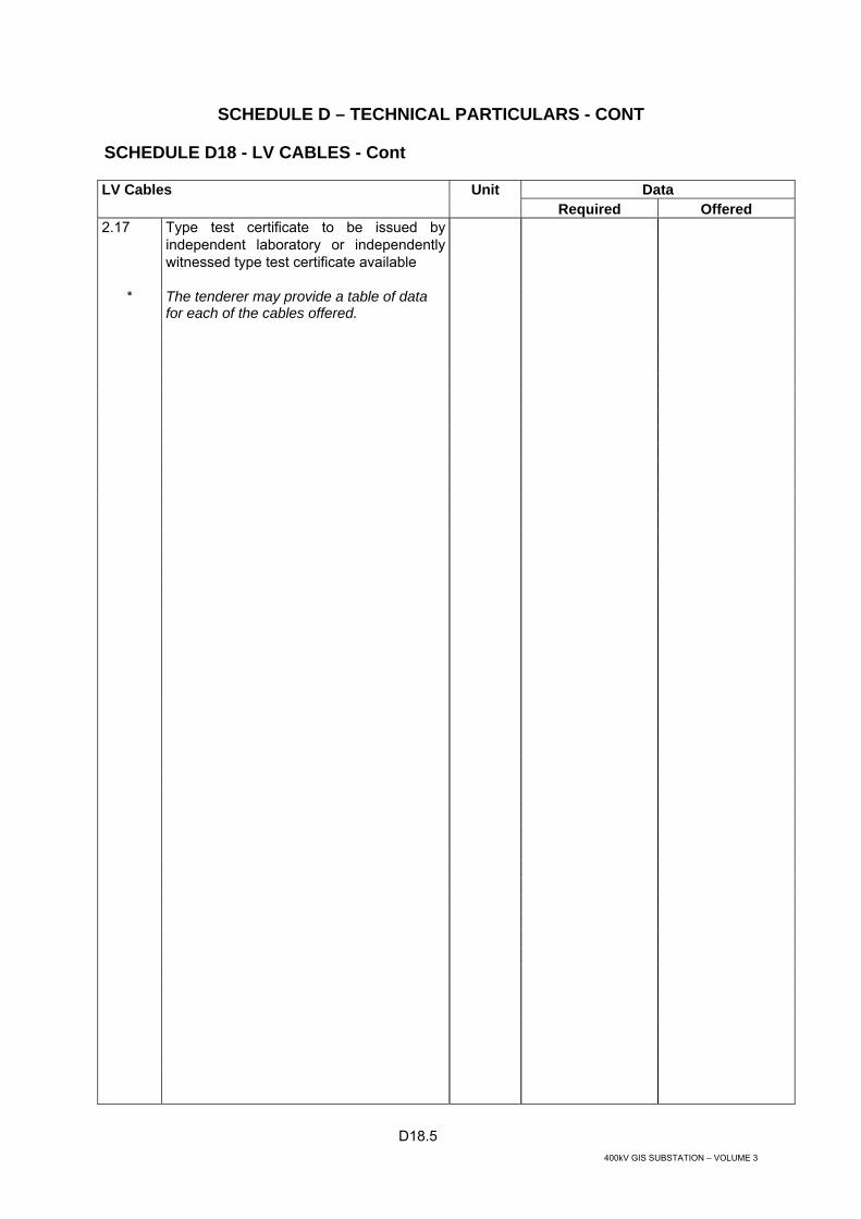
D18.5 400kV GIS SUBSTATION – VOLUME 3
SCHEDULE D – TECHNICAL PARTICULARS - CONT
SCHEDULE D18 - LV CABLES - Cont
Data LV Cables Unit Required Offered
2.17 Type test certificate to be issued by independent laboratory or independently witnessed type test certificate available
* The tenderer may provide a table of data for each of the cables offered.

D19.1 400kV GIS SUBSTATION – VOLUME 3
SCHEDULE D – TECHNICAL PARTICULARS - CONT
SCHEDULE D19 - PROTECTION SYSTEM
General Protection Requirements Unit Data Required Offered 1 OPERATING PERAMETERS
1.1 Auxiliary voltage range (Vn = 110Vdc) Vdc 77→150
1.2 Input frequency range (50Hz nominal) Hz 47.5→52.5
2 TYPE TESTS
2.1 Atmospheric Environment
Operation -25C and 55C for 96hrs, IEC 60068-2-1 Yes
Transport/storage -25C and 70C for 96hrs, IEC 60068-2-2 Yes
2.2 Relative Humidity
Operation at 93% Yes
Tested to IEC 60068-2-78 with severity class 56 days Yes
2.3 Enclosure
IEC 60529 IP50 Yes
2.4 Mechanical Environment
Vibration IEC 60255-21-1 Yes Shock and bump IEC 60255-21-2 Yes Seismic IEC 60255-21-3 Yes
2.5 Insulation
Rated insulation
1000 V high impedance protection CT inputs
250 V for other circuits Yes
1000 V open contact withstand Yes
Dielectric Tests
IEC 60255-5 – Series C of table 1 Yes
Impulse voltage
IEC 60255-5 test voltage 5 kV Yes

D19.2 400kV GIS SUBSTATION – VOLUME 3
SCHEDULE D – TECHNICAL PARTICULARS - CONT
SCHEDULE D19 - PROTECTION SYSTEM - Cont
General Protection Requirements Unit Data Required Offered 2.6 Electromagnetic Compatibility
1 MHz Burst disturbance tes
IEC 60255-22-1 severity class III
Yes
Electrostatic Discharge IEC 60255-22-2 severity class III
Yes
Radiated Electromagnetic Field Disturbance
IEC 60255-22-3 severity class III
Test method A, 27MHz through 500MHz
Yes
Electromagnetic Emissions
IEC 60255-25
Yes
Fast Transient Disturbance
IEC 60255-22-4 severity level IV
As appropriate

D19.3 400kV GIS SUBSTATION – VOLUME 3
SCHEDULE D – TECHNICAL PARTICULARS - CONT
SCHEDULE D19 - PROTECTION SYSTEM - Cont
Distance Protection Unit Data Required Offered 1 MANUFACTURER
2 TYPE REFERENCE
3 RELAY DESIGN (MICROPROCESSOR BASED, NUMERICAL)
Numerical
4 DISTANCE PROTECTION REQUIREMENTS
4.1 3 zone ph-ph & ph-E Yes
4.2 Phase fault & Earth fault characteristic shapes (Mho, Quad)
4.3 Operating time <30ms
4.4 Switch On To Fault Yes
4.5 Power swing blocking (depending on relaying point in the power system)
Yes
4.6 Voltage transformer supervision Yes
4.7 Time delays for all zones Yes
4.8 Zone enable/disable for all zone Yes
4.9 Teleprotection modes PUR/POR/Block (Selectable) Yes
4.10 DEF plain & Blocking modes (Selectable) Yes
4.11 Z1 min and max operating time (mid zone) ms <30
5 OTHER REQUIREMENTS
5.1 Thermal overload, (49) Yes
5.2 Circuit breaker failure. 50BF- (dependent on application) Yes
5.3 Event recording function Yes
5.4 Disturbance recording function Yes
5.5 Fault locator function Yes
5.6 Integral operator interface for local interrogation
Yes
5.7 Programmable scheme logic Yes

D19.4 400kV GIS SUBSTATION – VOLUME 3
SCHEDULE D – TECHNICAL PARTICULARS - CONT
SCHEDULE D19 - PROTECTION SYSTEM - Cont
Distance Protection Unit Data Required Offered 5.8 User-friendly HMI, Windows based software for relay setting,
relay configuration and event, disturbance and fault record management.
Yes
5.9 Tripping contacts rating Carry continuous 5A Make 30A maximum for 0.2s Break dc 50W resistive 25W inductive(L/R40ms)
Yes
5.10 Self checking facility
Yes
5.11 Integral intertrip send and receive, with external input interface Intertrip send and receive operate time
Yes
6 COMMUNICATIONS
6.1 Protection
Direct optical fibre 1300nm single mode Others (please list)
Yes
6.2 Control
Communication ports (Front/rear etc) Physical links (RS485/Fibre optic) Protocols supported IEC 60870-5-103 Yes others
6.3 TYPE TEST CERTIFICATE PROVIDED
Yes

D19.5 400kV GIS SUBSTATION – VOLUME 3
SCHEDULE D – TECHNICAL PARTICULARS - CONT
SCHEDULE D19 - PROTECTION SYSTEM - Cont
Feeder Differential Protection Unit Data Required Offered 1 MANUFACTURER
2 TYPE REFERENCE
3 RELAY DESIGN (MICROPROCESSOR BASED, NUMERICAL)
Numerical
4 FEEDER DIFFERENTIAL PROTECTION REQUIREMENTS
4.1 Fault settings (% of relay rating)
4.2 Minimum current at one feeder end for relay operation at that end:
(a) Phase faults (b) Earth faults
4.3 Minimum current at one feeder end for relay operation at both feeder ends:
(a) Phase faults (b) Earth faults
4.4 Effect of load current on settings given in 3.5, 3.6 above
4.5 Operating time at 5 x setting
45ms
4.6 Maximum primary out-of-zone fault current at which protection is stable
4.7 Insulation level between pilot wires and relay equipment 15 kV
5 PILOT WIRE REQUIREMENTS:
5.1 Number of cores
5.2 Insulation level between cores
5.3 Insulation level between cores and cable sheath
5.4 Any other requirements
6 PILOT WIRE SUPERVISION Check Relay (Setting ranges - Ph F 0.4In – 2.0In, EF 0.2In –0.8In)
Yes
Yes
7 TWO WAY INTERTRIP FUNCTION

D19.6 400kV GIS SUBSTATION – VOLUME 3
SCHEDULE D – TECHNICAL PARTICULARS - CONT
SCHEDULE D19 - PROTECTION SYSTEM - Cont
Feeder Differential Protection Unit Data Required Offered 8 TRIPPING CONTACTS RATING
Carry continuous 5A Make 30A maximum for 0.2s Break dc 50W resistive 25W inductive (L/R40ms)
9 SELF-MONITORING
10 TYPE TEST CERTIFICATE PROVIDED
Yes

D19.7 400kV GIS SUBSTATION – VOLUME 3
SCHEDULE D – TECHNICAL PARTICULARS - CONT
SCHEDULE D19 - PROTECTION SYSTEM - Cont
Main Transformer Biased Differential Protection Unit Data Required Offered 1 MANUFACTURER
2 TYPE REFERENCE
3 RELAY DESIGN (MICROPROCESSOR BASED, NUMERICAL)
numerical
4 BIASED DIFFERENTIAL FUNCTION
4.1 Operation time at 5 times setting
ms <25
4.2 Adjustable bias characteristics
Yes
4.3 Differential current stage Id >>
Yes
4.4 Magnetisation inrush restraint
Yes
4.5 “5th” Harmonic inrush restraint
Yes
4.6 Maximum through fault current for which relay remains stable (multiple of rating)
4.7 CT ratio and vector group compensation
5 RESTRICTED EARTH FAULT FUNCTION
5.1 HV REF
Not used
5.2 LV REF
Not used
5.3 Principle of operation High impedance/Low impedance
High
5.4 Metrosil requirements
5.5 Operation time at 5 times settings
ms <30
6 OTHER REQUIREMENTS
6.1 Phase overcurrent function 50/51 (requirement depending on application)
6.2 Earth fault protection 51N (requirement depending on application)
6.3 Integral operator interface for local interrogation
Yes
6.4 Programmable scheme logic
Yes

D19.8 400kV GIS SUBSTATION – VOLUME 3
SCHEDULE D – TECHNICAL PARTICULARS - CONT
SCHEDULE D19 - PROTECTION SYSTEM - Cont
Main Transformer Biased Differential Protection Unit Data Required Offered 6.5 User-friendly HMI, Windows based software for relay setting,
relay configuration and event, disturbance and fault record management.
Yes
6.6 Tripping contacts rating Carry continuous 5A Make 30A maximum for 0.2s Break dc 50W resistive 25W inductive (L/R40ms)
6.7 Event recording function
Yes
6.8 Disturbance recording function
Yes
6.9 Fault recording function
Yes
6.10 Self monitoring and alarm facility
6.11 Integral intertrip send and receive
7 COMMUNICATIONS
7.1 Control
7.2 Communication ports (Front/rear etc)
7.3 Physical links (RS485/Fibre optic)
7.4 Protocols supported
• IEC 60870-5-103 Yes • others
8 TYPE TEST CERTIFICATE PROVIDED
Yes

D19.9 400kV GIS SUBSTATION – VOLUME 3
SCHEDULE D – TECHNICAL PARTICULARS - CONT
SCHEDULE D19 - PROTECTION SYSTEM - Cont
Low Impedance Busbar Protection Including Breaker Failure Unit Data Protection Required Offered 1 MANUFACTURER
2 TYPE REFERENCE
3 RELAY DESIGN (MICROPROCESSOR-BASED, NUMERICAL)
Numerical
State principle of operation, i.e. low impedance
Low Z
4 LOW IMPEDANCE BUSBAR PROTECTION INCLUDING BREAKER FAILURE PROTECTION FUNCTIONS
4.1 Integral check zone feature (state principle of operation)
Yes
4.2 Distributed Bay Modules and Central Unit (Y/N)
Yes
4.3 Maximum number of Bays
4.4 Isolator replica
4.5 CT saturation detector and stabilisation
4.5 Integral CT supervision
4.6 CT matching functions
4.7 Phase segregated protection
4.8 Sensitivity
(a) Phase faults A sec’y (b) Earth faults
A sec’y
4.9 Operating time at 5 x fault setting
ms 30
4.10 Two stage Circuit Breaker Failure Adjustable current setting Adjustable time delays per stage
Yes
5 OTHER REQUIREMENTS
5.1 User-friendly HMI, Windows based software for relay setting, relay configuration and event, disturbance and fault record management.
Yes
5.2 Tripping contacts rating Carry continuous 5A Make 30A maximum for 0.2s Break dc 50W resistive 25W inductive (L/R40ms)
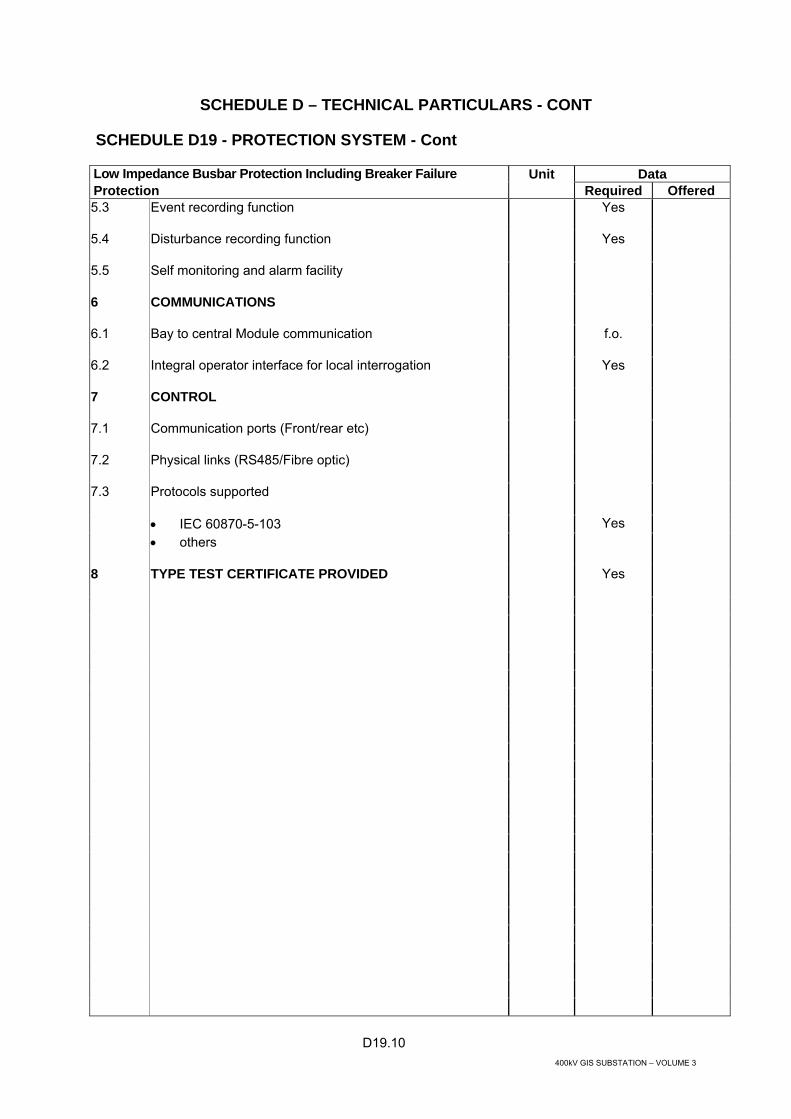
D19.10 400kV GIS SUBSTATION – VOLUME 3
SCHEDULE D – TECHNICAL PARTICULARS - CONT
SCHEDULE D19 - PROTECTION SYSTEM - Cont
Low Impedance Busbar Protection Including Breaker Failure Unit Data Protection Required Offered 5.3 Event recording function
Yes
5.4 Disturbance recording function
Yes
5.5 Self monitoring and alarm facility
6 COMMUNICATIONS
6.1 Bay to central Module communication
f.o.
6.2 Integral operator interface for local interrogation
Yes
7 CONTROL
7.1 Communication ports (Front/rear etc)
7.2 Physical links (RS485/Fibre optic)
7.3 Protocols supported
• IEC 60870-5-103 Yes • others
8 TYPE TEST CERTIFICATE PROVIDED
Yes

D19.11 400kV GIS SUBSTATION – VOLUME 3
SCHEDULE D – TECHNICAL PARTICULARS - CONT
SCHEDULE D19 - PROTECTION SYSTEM - Cont
Multi-Functional Overcurrent & Earth Fault Protection Unit Data Required Offered 1 MANUFACTURER
2 TYPE REFERENCE
3 RELAY DESIGN (MICROPROCESSOR-BASED, NUMERICAL)
Numerical
4 MULTI-FUNCTIONAL OVERCURRENT & EARTH FAULT PROTECTION FUNCTIONS
4.1 Number of phase CT inputs
4.2 Number of earth fault CT inputs
4.3 Standard, Very and Extreme Inverse and definite time characteristics curves conforming to IEC 60255
Yes
4.4 Number of inverse overcurrent functions (per phase)
4.5 Number of high set overcurrent functions (per phase)
4.6 Number of low set overcurrent functions (per phase)
4.7 Number of inverse earth fault functions
4.8 Number of high set earth fault functions
4.9 Number of low set earth fault functions
4.10 Number of group settings
4.11 Earth fault element suitable of high impedance REF (with external resistor)
Yes
4.12 Operating time at 5 x setting when configured for REF
ms 30
4.13 Suitable for Blocked Overcurrent busbar protection scheme
Yes
5 OTHER FUNCTIONS PROVIDED • Thermal overload 49 • Directional OC&EF
Y/N Y/N
5.1 Number of output relays • Rated for tripping • Rated for control and alarm
5.2 Integral metering functions
Yes
5.3 Opto-isolator inputs
Yes

D19.12 400kV GIS SUBSTATION – VOLUME 3
SCHEDULE D – TECHNICAL PARTICULARS - CONT
SCHEDULE D19 - PROTECTION SYSTEM - Cont
Multi-Functional Overcurrent & Earth Fault Protection Unit Data Required Offered 5.4 Programmable scheme logic
Yes
5.5 Event and Fault recording functions
5.6 Self-monitoring facility
5.7 User-friendly HMI, Windows based software for relay setting, relay configuration and event, disturbance and fault record management.
Yes
5.8 Tripping contacts rating Carry continuous 5A Make 30A maximum for 0.2s Break dc 50W resistive 25W inductive (L/R40ms)
6 COMMUNICATIONS
6.1 Integral operator interface for local interrogation
Yes
7 CONTROL
7.1 Communication ports (Front/rear etc)
7.2 Physical links (RS485/Fibre optic)
7.3 Protocols supported
• IEC 60870-5-103 Yes • others
8 TYPE TEST CERTIFICATE PROVIDED
Yes

D19.13 400kV GIS SUBSTATION – VOLUME 3
SCHEDULE D – TECHNICAL PARTICULARS - CONT
SCHEDULE D19 - PROTECTION SYSTEM - Cont
Multi-Functional Directional Overcurrent & Earth Fault Protection Unit Data Required Offered 1 MANUFACTURER
2 TYPE REFERENCE
3 RELAY DESIGN (MICROPROCESSOR-BASED, NUMERICAL)
Numerical
4 MULTI-FUNCTIONAL DIRECTIONAL OVERCURRENT & EARTH FAULT PROTECTION FUNCTIONS
4.1 Number of phase CT inputs
4.2 Number of earth fault CT inputs
4.3 Three phase VT input
Yes
4.4 Method of determining zero sequence voltage • Broken delta VT input • Derived mathematically
Y/N Y/N
4.5 Standard, Very and Extreme Inverse and definite time characteristics curves conforming to IEC 60255
Yes
4.6 Number of inverse DOC overcurrent functions (per phase)
4.7 Number of high set DOC functions (per phase)
4.8 Number of low set DOC functions (per phase)
4.9 Number of inverse DEF functions
4.10 Number of high set DEF functions
4.11 Number of low set DEF functions
4.12 Number of group settings
5 OTHER FUNCTIONS PROVIDED
5.1 • Non-directional overcurrent 50/51
Y/N
5.2 • Non-directional earth fault 50 N/51 N
Y/N
5.3 • Thermal overload 49
Y/N
5.4 • Suitable for Blocked Overcurrent busbar protection scheme

D19.14 400kV GIS SUBSTATION – VOLUME 3
SCHEDULE D – TECHNICAL PARTICULARS - CONT
SCHEDULE D19 - PROTECTION SYSTEM - Cont
Multi-Functional Directional Overcurrent & Earth Fault Protection Unit Data Required Offered 5.5 • Earth fault element suitable of high impedance REF
(with external resistor)
5.6 Number of output relays • Rated for tripping • Rated for control and alarm
5.7 Integral metering functions
Yes
5.8 Opto-isolator inputs
Yes
5.9 Programmable scheme logic
Yes
5.10 Event and Fault recording functions
5.11 Self-monitoring facility
5.12 User-friendly HMI, Windows based software for relay setting, relay configuration and event, disturbance and fault record management.
Yes
5.13 Tripping contacts rating Carry continuous 5A Make 30A maximum for 0.2s Break dc 50W resistive 25W inductive (L/R40ms)
6 COMMUNICATIONS
6.1 Integral operator interface for local interrogation
Yes
7 CONTROL
7.1 Communication ports (Front/rear etc)
7.2 Physical links (RS485/Fibre optic)
7.3 Protocols supported
• IEC 60870-5-103 Yes • Others
8 TYPE TEST CERTIFICATE PROVIDED
Yes

D19.15 400kV GIS SUBSTATION – VOLUME 3
SCHEDULE D – TECHNICAL PARTICULARS - CONT
SCHEDULE D19 - PROTECTION SYSTEM - Cont
Differential Protection and Back-Up Distance Unit Data Required Offered 1 MANUFACTURER
2 TYPE REFERENCE
3 RELAY DESIGN (MICROPROCESSOR BASED, NUMERICAL)
Numerical
4 DIFFERENTIAL PROTECTION REQUIREMENTS
4.1 Phase segregated protection
Yes
4.2 Ratio and Vector correction for CTs
Yes
4.3 Adjustable biased differential protection characteristic
Yes
4.4 Sensitivity:
- For phase faults - For earth faults
4.5 Operating time
ms <30
5 DISTANCE PROTECTION REQUIREMENTS
5.1 Zone ph-ph & ph-E
Yes
5.2 Phase fault & Earth fault characteristic shapes (Mho, Quad)
5.3 Operating time
<30ms
5.4 Switch On To Fault
Yes
5.5 Power swing blocking (depending on relaying point in the power system)
Yes
5.6 Voltage transformer supervision
Yes
5.7 Time delays for all zones
Yes
5.8 Zone enable/disable for all zones
Yes
6 OTHER REQUIREMENTS
6.1 Thermal overload, 49 – (requirement if cable over-temperature unsuitable for tripping)
Yes
6.2 Circuit breaker failure. 50BF- (dependent on application)
Yes
6.3 Event recording function
Yes
6.4 Disturbance recording function Yes

D19.16 400kV GIS SUBSTATION – VOLUME 3
SCHEDULE D – TECHNICAL PARTICULARS - CONT
SCHEDULE D19 - PROTECTION SYSTEM - Cont
Differential Protection and Back-Up Distance Unit Data Required Offered 6.5 Fault locator function
Yes
6.6 Integral operator interface for local interrogation
Yes
6.7 Programmable scheme logic
Yes
6.8 User-friendly HMI, Windows based software for relay setting, relay configuration and event, disturbance and fault record management.
Yes
6.9 Tripping contacts rating Carry continuous 5A Make 30A maximum for 0.2s Break dc 50W resistive 25W inductive(L/R40ms)
Yes
6.10 Self checking facility
Yes
6.11 Integral intertrip send and receive, with external input interface
Yes
7 COMMUNICATIONS
7.1 Protection
Direct optical fibre 1300nm single mode
Yes
7.2 Control
Communication ports (Front/rear etc)
Physical links (RS485/Fibre optic)
Protocols supported
IEC 60870-5-103 Yes others 8 TYPE TEST CERTIFICATE PROVIDED
Yes

D19.17 400kV GIS SUBSTATION – VOLUME 3
SCHEDULE D – TECHNICAL PARTICULARS - CONT
SCHEDULE D19 - PROTECTION SYSTEM - Cont
Restricted Earth Fault Protection Unit Data Required Offered 1 MANUFACTURER
2 TYPE REFERENCE
3 RELAY DESIGN (MICROPROCESSOR-BASED, NUMERICAL, E-M)
Numerical
4 RESTRICTED EARTH FAULT PROTECTION FUNCTIONS
4.1 Estimated minimum fault setting (% of CT rating)
%
4.2 Operating time at 5 x setting
ms
4.3 State principle of operation,
• H = high impedance • L = low impedance
4.4 Metrosils provided
4.5 Self monitoring (excluding EM)
Yes
4.6 User-friendly HMI, Windows based software for relay setting, relay configuration and event, disturbance and fault record management.
4.7 Tripping contacts rating Carry continuous 5A Make 30A maximum for 0.2s Break dc 50W resistive 25W inductive (L/R40ms)
4.8 Communications (numerical relays)
4.9 Integral operator interface for local interrogation
Yes
5 CONTROL
5.1 Communication ports (Front/rear etc)
5.2 Physical links (RS485/Fibre optic)
5.3 Protocols supported
• IEC 60870-5-103 • others
Yes
6 TYPE TEST CERTIFICATE PROVIDED Yes

D19.18 400kV GIS SUBSTATION – VOLUME 3
SCHEDULE D – TECHNICAL PARTICULARS - CONT
SCHEDULE D19 - PROTECTION SYSTEM - Cont
Trip Circuit Supervision Unit Data Required Offered 1 MANUFACTURER
2 TYPE REFERENCE
3 RELAY DESIGN (MICROPROCESSOR, BASED NUMERICAL)
Numerical
4 TRIP CIRCUIT SUPERVISION FUNCTIONS
4.1 Operating time
ms
4.2 Supervision of the whole trip circuit with CB open and closed.
Yes
4.3 Relay operated indicator
Yes
5 TYPE TEST CERTIFICATE PROVIDED
Yes

D19.19 400kV GIS SUBSTATION – VOLUME 3
SCHEDULE D – TECHNICAL PARTICULARS - CONT
SCHEDULE D19 - PROTECTION SYSTEM - Cont
Multi-Contact Tripping Relays Unit Data Required Offered 1 MANUFACTURER
2 TYPE REFERENCE
3 MULTI-CONTACT TRIPPING RELAYS FUNCTIONS
3.1 Operating time
ms <12
3.2 Is relay mechanically latched or self resetting?
3.3 Method used to reset latched relay (hand or electrical)
3.4 Burden at rated voltage
3.5 Minimum voltage at which reliable operation occurs
3.6 Tripping contacts rating Carry continuous 5A Make 30A maximum for 0.2s Break dc 50W resistive 25W inductive (L/R40ms)
3.7 Relay operated indicator type
4 TYPE TEST CERTIFICATE PROVIDED
Yes

D20.1 400kV GIS SUBSTATION – VOLUME 3
SCHEDULE D – TECHNICAL PARTICULARS - CONT
SCHEDULE D20 - SUBSTATION CONTROL SYSTEM
Substation Control System Unit Data Required Offered 1 SUBSTATION CONTROL SYSTEM Yes
2 MASTER CONTROL UNIT
2.1 Substation Computer
2.1.1 Manufacturer Yes
2.1.2 Model Yes
2.1.3 Processor
2.1.4 Type
2.1.5 Word length Bits
2.1.6 Clock speed (minimum) MHz
2.1.7 Memory size
2.1.8 Supplied (minimum) Mb
2.1.9 Supportable/expandable Gb
2.1.10 Hard disk size
2.1.11 Supplied (minimum) Gb
2.1.12 Supportable/expandable Gb
2.1.13 Optical Storage Yes
2.1.14 Operating system
2.1.15 Software supplied
2.1.16 Operating temperature range °C
2.1.17 Maximum relative humidity %
2.1.18 Nominal voltage V ac
2.1.19 Operating frequency Hz
2.1.20 Starting current A
2.1.21 Power requirement W
2.1.22 Mean time between failure h
2.1.23 Mean time to repair h
2.2 Gateway
2.2.1 Manufacturer Yes

D20.2 400kV GIS SUBSTATION – VOLUME 3
SCHEDULE D – TECHNICAL PARTICULARS - CONT
SCHEDULE D20 - SUBSTATION CONTROL SYSTEM - Cont
Substation Control System Unit Data Required Offered 2.2.2 Model Yes
2.2.3 Processor
2.2.4 Type
2.2.5 Word length Bits
2.2.6 Clock speed (minimum) MHz
2.2.7 Memory size
2.2.8 Supplied (minimum) Mb
2.2.9 Supportable/expandable Gb
2.2.10 Hard disk size
2.2.11 Supplied (minimum) Gb
2.2.12 Supportable/expandable Gb
2.2.13 Communication Protocols To Control Centre(s)
2.2.14 NCC Main IEC 60870-5-101 Yes
2.2.15 NCC Alt IEC 60870-5-101 Yes
2.2.16 NCC TCP/IP Intranet Yes
2.2.17 DCC Main IEC 60870-5-101 Yes
2.2.18 DCC Alt IEC 60870-5-101 Yes
2.2.19 NCC IEC 60870-5-104 Yes
2.2.20 DCC IEC 60870-5-104 Yes
2.2.21 Communication Protocols in Substation
2.2.22 NCC IEC 60870-5-103 Yes
2.2.23 DCC IEC 60870-5-103 Yes
2.2.24 NCC IEC 60870-5-101 Yes
2.2.25 DCC IEC 60870-5-101 Yes
2.2.26 List other operating Protocols
2.2.28 V.35 interface at 64Kb/s Yes
2.2.29 X.21 / V.11 interface at 64Kb/s Yes
2.2.30 Operating system

D20.3 400kV GIS SUBSTATION – VOLUME 3
SCHEDULE D – TECHNICAL PARTICULARS - CONT
SCHEDULE D20 - SUBSTATION CONTROL SYSTEM - Cont
Substation Control System Unit Data Required Offered 2.2.31 Operating temperature range °C
2.2.32 Maximum relative humidity %
2.2.33 Nominal voltage V dc
2.2.34 Operating frequency Hz
2.2.35 Starting current A
2.2.36 Power requirement W
2.2.37 Mean time between failure h
2.2.38 Mean time to repair h
2.3 Operator Workstations / HMI
2.3.1 Manufacturer Yes
2.3.2 Model Yes
2.3.3 Literature reference for principle of operation Yes
2.3.4 Processor
2.3.5 Type
2.3.6 Word length Bits
2.3.7 Clock speed (minimum) MHz
2.3.8 Memory size
2.3.9 Supplied (minimum) Mb
2.3.10 Supportable/expandable Gb
2.3.11 Hard disk size
2.3.12 Supplied (minimum) Gb
2.3.13 Supportable/expandable Gb
2.3.14 Optical Storage Yes
2.3.15 Pointer Device
2.3.16 Operating system
2.3.17 Operator interface screens
2.3.18 Operating temperature range °C
2.3.19 Maximum relative humidity %
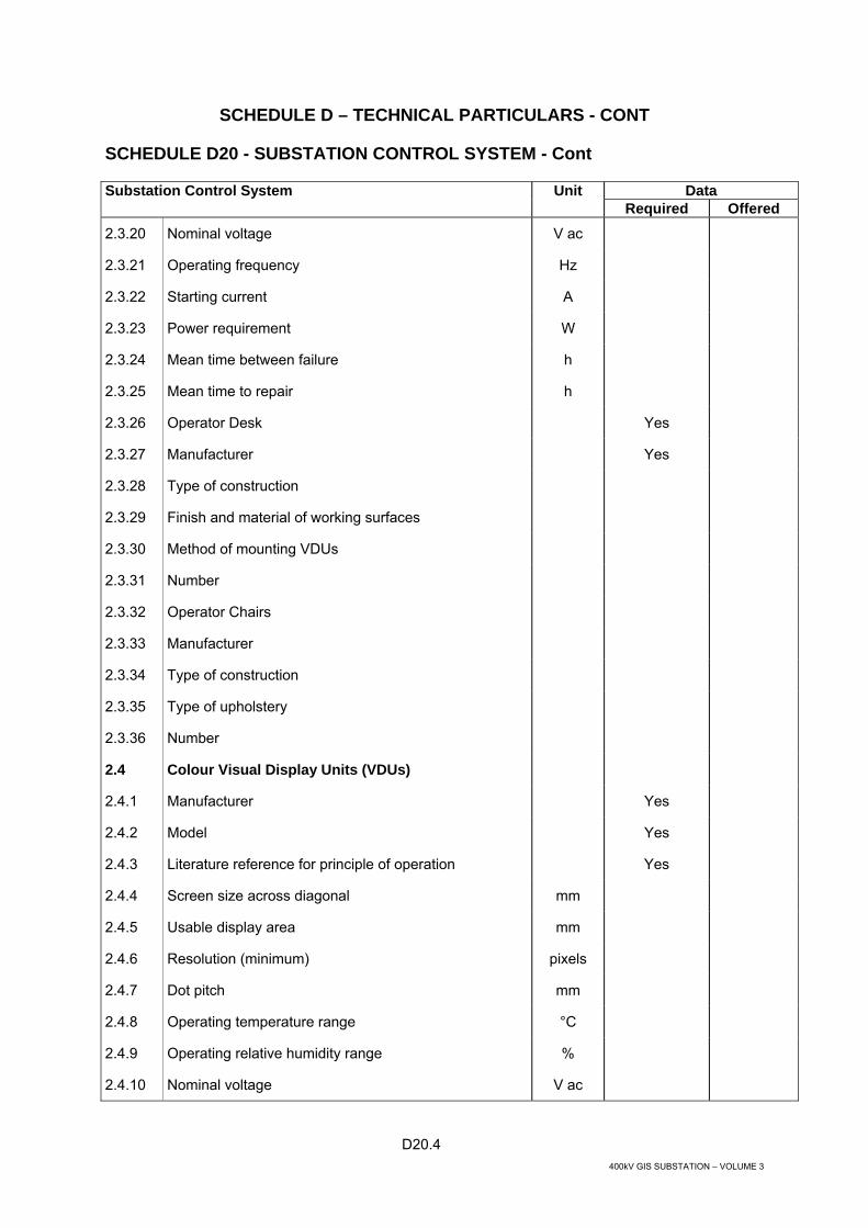
D20.4 400kV GIS SUBSTATION – VOLUME 3
SCHEDULE D – TECHNICAL PARTICULARS - CONT
SCHEDULE D20 - SUBSTATION CONTROL SYSTEM - Cont
Substation Control System Unit Data Required Offered 2.3.20 Nominal voltage V ac
2.3.21 Operating frequency Hz
2.3.22 Starting current A
2.3.23 Power requirement W
2.3.24 Mean time between failure h
2.3.25 Mean time to repair h
2.3.26 Operator Desk Yes
2.3.27 Manufacturer Yes
2.3.28 Type of construction
2.3.29 Finish and material of working surfaces
2.3.30 Method of mounting VDUs
2.3.31 Number
2.3.32 Operator Chairs
2.3.33 Manufacturer
2.3.34 Type of construction
2.3.35 Type of upholstery
2.3.36 Number
2.4 Colour Visual Display Units (VDUs)
2.4.1 Manufacturer Yes
2.4.2 Model Yes
2.4.3 Literature reference for principle of operation Yes
2.4.4 Screen size across diagonal mm
2.4.5 Usable display area mm
2.4.6 Resolution (minimum) pixels
2.4.7 Dot pitch mm
2.4.8 Operating temperature range °C
2.4.9 Operating relative humidity range %
2.4.10 Nominal voltage V ac

D20.5 400kV GIS SUBSTATION – VOLUME 3
SCHEDULE D – TECHNICAL PARTICULARS - CONT
SCHEDULE D20 - SUBSTATION CONTROL SYSTEM - Cont
Substation Control System Unit Data Required Offered 2.4.11 Operating frequency Hz
2.4.12 Starting current A
2.4.13 Power requirement W
2.4.14 Approximate lifetime of monitor under continuous use h
2.4.15 Mean time between failure h
2.4.16 Mean time to repair h
2.5 Substation Local Area Network (LAN)
2.5.1 Architecture and Technology Yes
2.5.2 Literature reference for principle of operation Yes
2.5.3 Transmission medium (e.g. optical fibre) and physical specification
2.5.4 Protocols
2.5.5 IEC 60870-5-101
2.5.6 IEC 60870-5-104
2.5.7 IEC 61850
2.5.8 List all other protocols
2.5.9 Data transmission rate(s) Mbps
2.5.10
Physical arrangement - Identify all main elements in the supply including hubs, concentrators, bridges, routers, gateways switches etc. and the number of each
Yes
2.5.11 For each element of the LAN indicate the
2.5.12 No and type of ports
2.5.13 % of spare for each type of port
2.5.14 Management software package, functions and facilities, and hardware platform
2.5.15 % Loading under various system activity scenarios including
2.5.16 normal loading for performance testing %
2.5.17 high loading for performance testing %
2.5.18 system power up %
2.5.19 main server fail-over and database resynchronisation
2.5.20 Overall availability %

D20.6 400kV GIS SUBSTATION – VOLUME 3
SCHEDULE D – TECHNICAL PARTICULARS - CONT
SCHEDULE D20 - SUBSTATION CONTROL SYSTEM - Cont
Substation Control System Unit Data Required Offered 2.6 Individual Elements
2.6.1 For each element of the LAN equipment provide the following information
2.6.2 Manufacturer
2.6.3 Type
2.6.4 Nominal voltage
2.6.5 Power requirements V ac
2.6.6 Range of ambient temp. and max relative humidity for continuous reliable operation W
2.6.7 Mean time between failures oC
2.6.8 Mean time to repair %RH
2.7 Printers
2.7.1 Logging Printer Yes
2.7.2 Manufacturer
2.7.3 Model
2.7.4 Literature reference for principle of operation
2.7.5 Number
2.7.6 Mounting arrangement
2.7.7 Method of printing (e.g. ink jet)
2.7.8 Print speed ppm
2.7.9 Paper feed mechanism
2.7.10 Number of columns (minimum)
2.7.11 Operating temperature range °C
2.7.12 Maximum relative humidity %
2.7.13 Nominal voltage V ac
2.7.14 Operating frequency Hz
2.7.15 Power requirement W
2.7.16 Max noise level at 1 m dB(A)
2.7.17 Mean time between failure h
2.7.18 Mean time to repair h

D20.7 400kV GIS SUBSTATION – VOLUME 3
SCHEDULE D – TECHNICAL PARTICULARS - CONT
SCHEDULE D20- SUBSTATION CONTROL SYSTEM - Cont
Substation Control System Unit Data Required Offered 2.7.19 Colour Printers
2.7.20 Manufacturer Yes
2.7.21 Model Yes
2.7.22 Literature reference for principle of operation Yes
2.7.23 Number
2.7.24 Mounting arrangement
2.7.25 Print speed (minimum) ppm
2.7.26 Technology
2.7.27 Resolution dpi
2.7.28 Paper size
2.7.29 Sheet feed paper tray capacity Sheets
2.7.30 Internal memory (minimum) Mb
2.7.31 Operating temperature range °C
2.7.32 Maximum relative humidity %
2.7.33 Nominal voltage V ac
2.7.34 Operating frequency Hz
2.7.35 Power requirement W
2.7.36 Max noise level at 1 m dB(A)
2.7.37 Mean time between failure h
2.7.38 Mean time to repair h

D20.8 400kV GIS SUBSTATION – VOLUME 3
SCHEDULE D – TECHNICAL PARTICULARS - CONT
SCHEDULE D20 - SUBSTATION CONTROL SYSTEM - Cont
Bay Control Unit Hardware Unit Data Required Offered 3 BAY CONTROL UNIT HARDWARE
3.1 General Yes
3.1.1 Manufacturer Yes
3.1.2 Module designation Yes
3.1.3 Literature reference for principle of operation Yes
3.1.4 Power supply V dc 110
3.1.5 Power requirements W
3.1.6 Maximum Number of expansion modules
3.1.7 Mean-time to repair for each type of RTU H
3.1.8 Mean-time between failure for each type of RTU H
3.1.9 Local LCD Display
3.1.10 Operating temperature range °C 0 – 50
3.1.11 Operating relative humidity range
3.2 BCU Enclosure
3.2.1 Manufacturer
3.2.2 Module designation
3.2.3 Literature reference for enclosure
3.2.4 Weight
3.2.5 Dimensions
3.2.6.0 Degree of protection
3.2.6.1 Flush Mounted housing
3.2.6.2 Surface mounted housing
3.3 IEC Standards ( Or Equivalent )
3.3.1 EMC Type tests (Provide Class/Level or Severity rating)
3.3.2 EMC Compliance IEC 60255-22-3
3.3.3 Dielectric withstand test IEC 60255--5
3.3.4 High Voltage impulse test IEC 60255-5
3.3.5 Fast transient disturbance test IEC 61000-4-4 and 60255-22-4

D20.9 400kV GIS SUBSTATION – VOLUME 3
SCHEDULE D – TECHNICAL PARTICULARS - CONT
SCHEDULE D20 - SUBSTATION CONTROL SYSTEM - Cont
Bay Control Unit Hardware Unit Data Required Offered 3.3.6 Oscillatory transient IEC 61000-4-12
3.3.7 Radiated immunity test IEC 61000-4-6 and 60255-22-3
3.3.8 Electrostatic discharge test IEC 61000-4-2 and 60255-22-2
3.3.9 1 MHz Burst disturbance test to IEC 60255-22-1
3.3.10 Electromagnetic emissions to IEC 60255-25
3.3.11 Emitted interference test IEC 61000-4-3
3.3.12 Mechanical test Compliance
3.3.13 Vibration test IEC 60255-21-1
3.3.14 Shock test IEC 60255-21-2
3.3.15 Seismic test IEC 60255-21-3
3.3.16 Temperature rise test IEC 60068-2-1 and 2-2
3.3.15 Relative humidity test 60068-2-78
3.3.16 Enclosure test to IEC 60529 IP50
3.4 BCU Functions
3.4.1 The monitoring functions include:
3.4.2 Switching status monitoring (breakers)
3.4.3 Indication & alarm status monitoring
3.4.4 Analogue measurements (currents, voltages, etc.)
3.4.5 Resolution of time tagging ms 1
3.4.6.0 The control functions include:
3.4.6.1 Close / open of circuit breakers
3.4.6.2 Close / Open of isolators / disconnectors
3.4.6.3 Transformer Automatic tap change control
3.4.6.4 Breaker Voltage Synchronisation Check Control
3.4.6.5 Bay interlocking facilities
3.4.7 The reporting functions include:
3.4.7.1 Sequence of Events recording
3.4.7.2 Post – Mortem Review / Fault waveform capture

D20.10 400kV GIS SUBSTATION – VOLUME 3
SCHEDULE D – TECHNICAL PARTICULARS - CONT
SCHEDULE D20 - SUBSTATION CONTROL SYSTEM - Cont
Bay Control Unit Hardware Unit Data Required Offered
3.4.7.3 Tenderers to state memory capacity and functionality of Sequence of events and fault waveform capture
3.5 BCU Configuration
3.5.1 Number of processors
3.5.2 Main processor
3.5.3 Secondary processors
3.5.4 Communication processor (module)
3.5.5 Type of communication between processors
3.5.6 LCD Display and selector Buttons on front of BCU Yes
3.5.6.1 Functionality to include
3.5.6.2 Full control of circuit bay
3.5.6.3 Status of bay plant
3.5.6.4 Circuit active line diagram
3.5.6.5 Power system Measurements
3.5.6.6 Display alarms and events
3.6 Processing Units
3.6.1 Main CPU
3.6.2 Manufacturer
3.6.3 Module designation
3.6.4 Literature reference for principle of operation
3.6.5 Mean - time between failure h
3.6.6 Power requirements W
3.6.7 Type of processor
3.6.8 Word length bit
3.6.9 Clock speed MHz
3.6.10 Kinds of memory used:
3.6.10.1 Type, size and extension capabilities KByte
3.6.10.2 Type, size and extension capabilities Kbytes
3.6.10.3 Type, size and extension capabilities Kbytes

D20.11 400kV GIS SUBSTATION – VOLUME 3
SCHEDULE D – TECHNICAL PARTICULARS - CONT
SCHEDULE D20 - SUBSTATION CONTROL SYSTEM - Cont
Bay Control Unit Hardware Unit Data Required Offered 3.7 Secondary CPU
3.7.1 Manufacturer
3.7.2 Module designation
3.7.3 Literature reference for principle of operation
3.7.4 Mean - time between failure h
3.7.5 Power requirements W
3.7.6 Type of processor
3.7.7 Word length bit
3.7.8 Clock speed MHz
3.7.9 Kinds of memory used:
3.7.9.1 Type, size and extension capabilities Kbytes
3.7.9.2 Type, size and extension capabilities Kbytes
3.7.9.3 Type, size and extension capabilities Kbytes
3.8 Communications
3.8.1 Manufacturer Yes
3.8.2 Module designation
3.8.3 Literature reference for principle of operation
3.8.4 Number of communications channels
3.8.5 Type of processor
3.8.6 Word length
3.8.7 Clock speed bit
3.8.8 Type and size of memory MHz
3.8.9 Line interface to communication channel
3.8.10 Kinds of memory used: B/s
3.8.11 Number and type of communication ports
3.8.12 Meantime between failure h
3.8.13 Power requirement W
3.8.14 Communication Interfaces

D20.12 400kV GIS SUBSTATION – VOLUME 3
SCHEDULE D – TECHNICAL PARTICULARS - CONT
SCHEDULE D20 - SUBSTATION CONTROL SYSTEM - Cont
Bay Control Unit Hardware Unit Data Required Offered 3.8.14.1 IEC60870-5-101 direct to Control Centre(s)
3.8.14.2 IEC60870-5-103 interface to protection IED
3.8.14.3 IEC61850 interface to substation LAN
3.8.14.4 IEC60870-5-101 for remote downloading of BCU data
3.8.14.5 List all Protocols available at BCU
3.8.15 Local interface for Laptop Computer
3.8.16 IED interface
3.8.16.1 List of manufactures the BCU has interfaced Yes
3.8.16.2 Standard communication protocols available Yes
3.8.16.3 Optional communication protocols available Yes
3.9 Power Supply Module
3.9.1 Module designation
3.9.2 Literature reference for principle of operation
3.9.3 Maximum number of modules per processor
3.9.4 Nominal Input voltage VDC
3.9.5 Operating voltage range
3.9.6 Power requirement W
3.9.7 Isolation
3.9.8 Meantime between failure h
3.9.9 Power requirement W
3.10 Digital Input Module
3.10.1 Module designation
3.10.2 Literature reference for principle of operation
3.10.3 Maximum number of modules per processor
3.10.4 Input voltage V dc
3.10.5 Is contact input type configurable as
3.10.5.1 Status and alarms
3.10.5.2 Sequence of events
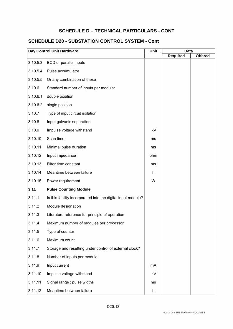
D20.13 400kV GIS SUBSTATION – VOLUME 3
SCHEDULE D – TECHNICAL PARTICULARS - CONT
SCHEDULE D20 - SUBSTATION CONTROL SYSTEM - Cont
Bay Control Unit Hardware Unit Data Required Offered 3.10.5.3 BCD or parallel inputs
3.10.5.4 Pulse accumulator
3.10.5.5 Or any combination of these
3.10.6 Standard number of inputs per module:
3.10.6.1 double position
3.10.6.2 single position
3.10.7 Type of input circuit isolation
3.10.8 Input galvanic separation
3.10.9 Impulse voltage withstand kV
3.10.10 Scan time ms
3.10.11 Minimal pulse duration ms
3.10.12 Input impedance ohm
3.10.13 Filter time constant ms
3.10.14 Meantime between failure h
3.10.15 Power requirement W
3.11 Pulse Counting Module
3.11.1 Is this facility incorporated into the digital input module?
3.11.2 Module designation
3.11.3 Literature reference for principle of operation
3.11.4 Maximum number of modules per processor
3.11.5 Type of counter
3.11.6 Maximum count
3.11.7 Storage and resetting under control of external clock?
3.11.8 Number of inputs per module
3.11.9 Input current mA
3.11.10 Impulse voltage withstand kV
3.11.11 Signal range : pulse widths ms
3.11.12 Meantime between failure h

D20.14 400kV GIS SUBSTATION – VOLUME 3
SCHEDULE D – TECHNICAL PARTICULARS - CONT
SCHEDULE D20 - SUBSTATION CONTROL SYSTEM - Cont
Bay Control Unit Hardware Unit Data Required Offered 3.11.13 Power requirement W
3.12 Command Output Module
3.12.1 Module designation
3.12.2 Literature reference for principle of operation
3.12.3 Maximum number of modules per processor
3.12.4 Contact ratings
3.12.4.1 Switched voltage V
3.12.4.2 Switched power VA max
3.12.4.3 Switched current A
3.12.4.4 Range of duration of command output S
3.12.5 Number of two position output channel per module
3.12.6 Are outputs activated by select-check-actuate procedure?
3.12.7 Are welded contacts checked prior to command output?
3.12.8 Are the outputs fused and fuse status monitored?
3.12.9 Impulse voltage withstand kV
3.12.10 Meantime between failure h
3.12.11 Power requirement W
3.13 Digital Output Module
3.13.1 Module designation
3.13.2 Literature reference for principle of operation
3.13.3 Number of outputs per module
3.13.4 Maximum number of modules per processor
3.13.5 Maximum output current mA
3.13.6 Maximum switched output voltage V
3.13.7 Impulse voltage withstand kV
3.13.8 Type of protection against back EMF kV
3.13.9 Command duration adjustable in the range s
3.13.10 Meantime between failure h
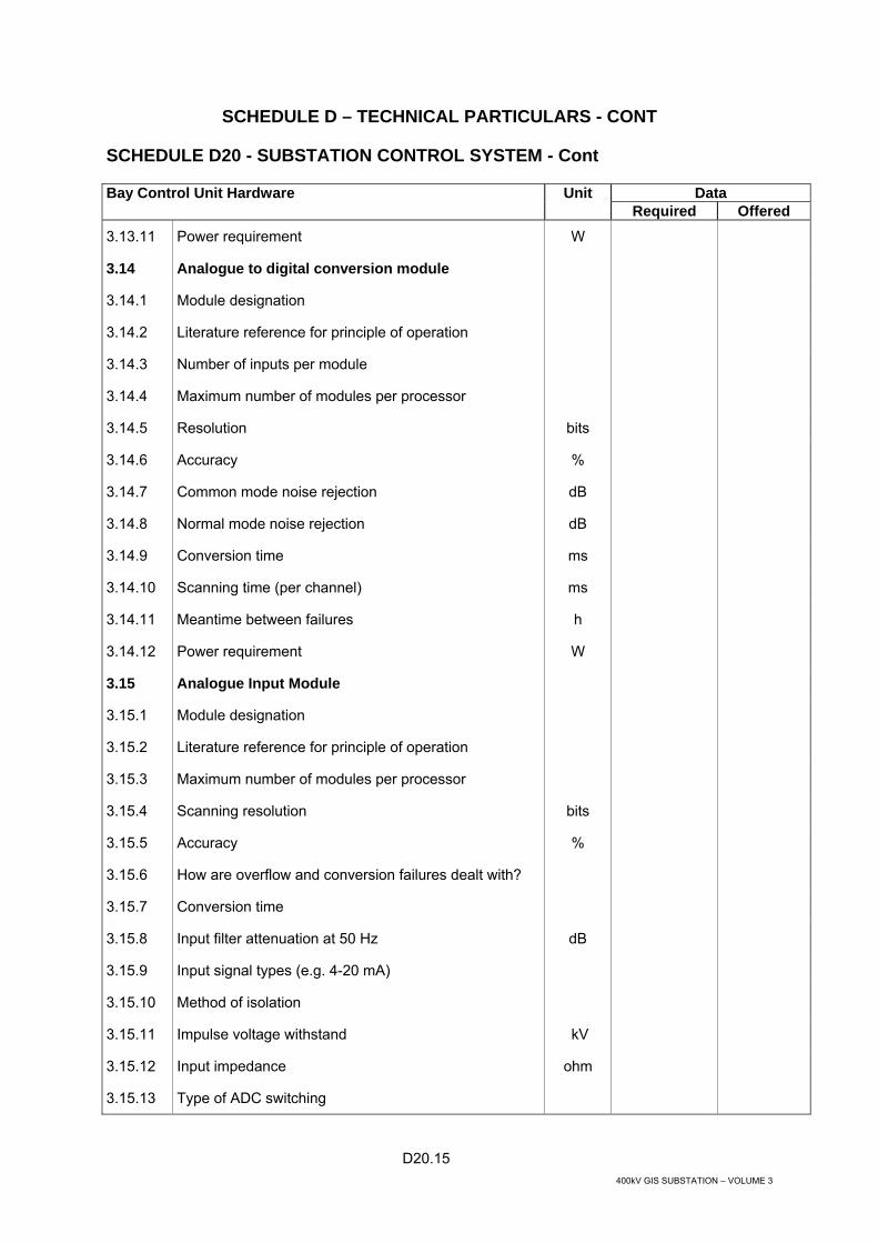
D20.15 400kV GIS SUBSTATION – VOLUME 3
SCHEDULE D – TECHNICAL PARTICULARS - CONT
SCHEDULE D20 - SUBSTATION CONTROL SYSTEM - Cont
Bay Control Unit Hardware Unit Data Required Offered 3.13.11 Power requirement W
3.14 Analogue to digital conversion module
3.14.1 Module designation
3.14.2 Literature reference for principle of operation
3.14.3 Number of inputs per module
3.14.4 Maximum number of modules per processor
3.14.5 Resolution bits
3.14.6 Accuracy %
3.14.7 Common mode noise rejection dB
3.14.8 Normal mode noise rejection dB
3.14.9 Conversion time ms
3.14.10 Scanning time (per channel) ms
3.14.11 Meantime between failures h
3.14.12 Power requirement W
3.15 Analogue Input Module
3.15.1 Module designation
3.15.2 Literature reference for principle of operation
3.15.3 Maximum number of modules per processor
3.15.4 Scanning resolution bits
3.15.5 Accuracy %
3.15.6 How are overflow and conversion failures dealt with?
3.15.7 Conversion time
3.15.8 Input filter attenuation at 50 Hz dB
3.15.9 Input signal types (e.g. 4-20 mA)
3.15.10 Method of isolation
3.15.11 Impulse voltage withstand kV
3.15.12 Input impedance ohm
3.15.13 Type of ADC switching

D20.16 400kV GIS SUBSTATION – VOLUME 3
SCHEDULE D – TECHNICAL PARTICULARS - CONT
SCHEDULE D20 - SUBSTATION CONTROL SYSTEM - Cont
Bay Control Unit Hardware Unit Data Required Offered 3.15.14 Standard number of inputs per module
3.15.15 Meantime between failure h
3.15.16 Power requirement W
3.16 Analogue Output Module
3.16.1 Module designation
3.16.2 Literature reference for principle of operation
3.16.3 Number of outputs per module
3.16.4 Maximum number of modules per processor
3.16.5 Output voltage range V
3.16.6 Output current range mA
3.16.7 Type of isolation
3.16.8 Load resistance range ohms
3.16.9 Maximum error over-current ranges %
3.16.10 Impulse voltage withstand kV
3.17 Direct AC Connection Voltage
3.17.1 Module designation
3.17.2 Literature reference for principle of operation
3.17.3 Maximum number of modules processor
3.17.4 Number of inputs per module
3.17.5 Input voltage ranges V ac
3.17.6 Input filter attenuation at 50 Hz dB
3.17.7 Burden on instrument transformer circuit VA
3.17.8 Conversion time ms
3.17.9 Scanning resolution bits
3.17.10 Accuracy %
3.17.11 What calculations are supported?
3.17.12 How are overflow and conversion failures dealt with?
3.17.13 Method of isolation

D20.17 400kV GIS SUBSTATION – VOLUME 3
SCHEDULE D – TECHNICAL PARTICULARS - CONT
SCHEDULE D20 - SUBSTATION CONTROL SYSTEM - Cont
Bay Control Unit Hardware Unit Data Required Offered 3.17.14 Impulse voltage withstand kV kV
3.18 Direct AC Connection Current
3.18.1 Module designation
3.18.2 Literature reference for principle of operation
3.18.3 Maximum number of modules processor
3.18.4 Number of inputs per module
3.18.5 Input current ranges A
3.18.6 Input filter attenuation at 50 Hz dB
3.18.7 Burden on instrument transformer circuit VA
3.18.8 Conversion time ms
3.18.9 Scanning resolution bits
3.18.10 Accuracy %
3.18.11 What calculations are supported?
3.18.12 How are overflow and conversion failures dealt with?
3.18.13 Method of isolation
3.18.14 Impulse voltage withstand kV kV

D20.18 400kV GIS SUBSTATION – VOLUME 3
SCHEDULE D – TECHNICAL PARTICULARS - CONT
SCHEDULE D20 - SUBSTATION CONTROL SYSTEM - Cont
BCU Software Unit Data Required Offered 4 BCU SOFTWARE
4.1 General Requirements
4.1.1 Program structure
4.1.2 System software
4.1.3 Standard functions programs
4.1.4 User functions programs
4.2 Capability of:
4.2.1 BCU program downloading from Control Centre
4.2.2 Application configuration from Control Centre
4.2.3 Remote selection of processing parameters
4.2.4 Selection of communication protocols
4.2.5 Selection of operation modes (cyclic, polled, etc.)
4.2.6 Appropriate protection of software against power failure
4.2.7 Automatic BCU re-start without software down-loading
4.3 System Software
4.3.1 Operating System (Monitor) Functions and capabilities
4.3.2 Calendar Program Type, Functions and capabilities
4.3.3 Time Synchronization Program Functions and capabilities
4.3.4 Database Updating Program Functions and capabilities
4.3.5 Testing and Diagnostics Programs Functions and capabilities
4.4 Standard Functions Programs
4.4.1 Data Communication Programs: Functions and capabilities
4.4.2 Capability of communication protocol selection
4.4.3 Capability of operating modes selection

D20.19 400kV GIS SUBSTATION – VOLUME 3
SCHEDULE D – TECHNICAL PARTICULARS - CONT
SCHEDULE D20 - SUBSTATION CONTROL SYSTEM - Cont
BCU Software Unit Data Required Offered
4.5 Analogue Measurements, Scanning and Transmission Programs
4.5.1 Capabilities of adjustments
4.5.2 Transducers constants
4.5.3 Periodic transmission/transmission by exception
4.5.4 Automatic checking of A/D-conversion accuracy
4.5.5 Smoothing
4.5.6 Threshold values
4.5.7 Limits
4.5.8 Scan duration (range)
4.5.9 Cycle duration (range) s
4.5.10 Priority of transmission s
4.5.11 Digital Input Data Scanning and Transmission Program
4.6 Functions and capabilities
4.6.1 Capability of adjustments
4.6.2 Scan duration (range) ms
4.6.3 Transient time of status information (range)
4.6.4 Cycle duration (range) ms
4.6.5 Debouncing filter s
4.6.6 Suppression of intermediate status information
4.6.7 Time tagging
4.6.8 Transmission mode
4.6.9 Priority of transmission
4.7 Alarm and Event handling
4.7.1 Grouping of alarms and events
4.7.2 Maximum number of groups
4.8.0 Supervisory Control Programs: Functions and capabilities
4.8.1 Select before execute
4.8.2 Target check

D20.20 400kV GIS SUBSTATION – VOLUME 3
SCHEDULE D – TECHNICAL PARTICULARS - CONT
SCHEDULE D20 - SUBSTATION CONTROL SYSTEM - Cont
BCU Software Unit Data Required Offered 4.8.3 Cancelling control after adjustable time delay
4.8.4 Capability of adjustments:
4.8.5 Duration of output (range) s
4.8.6 Allowed duration of execution (range) s
4.8.7 Sequence of Events programs
4.8.8 Minimal sequence of events time resolution ms
4.8.9 Sequence of events memory capacity
4.8.10 Events time resolution (adjustable range)
4.8.11 Priority of transmission
4.8.12 Post - Mortem Review / Program
4.8.13 Selection of analogues for post-mortem review
4.8.14 Short interval time resolution (adjustable range) s
4.8.15 Long interval time resolution (adjustable range) s
4.9 Data processing programs: Functions and capabilities
4.9.1 Required minimum data processing:
4.9.2 Logic functions
4.9.3 Arithmetical functions (MW , Mvar etc )
4.9.4 Limiting functions s
4.9.5 Comparative functions
4.9.6 Time functions

D20.21 400kV GIS SUBSTATION – VOLUME 3
SCHEDULE D – TECHNICAL PARTICULARS - CONT
SCHEDULE D20 - SUBSTATION CONTROL SYSTEM - Cont
Gateway Software Unit Data Required Offered 5. GATEWAY SOFTWARE
5.1 General Requirements
5.1.1 Database management application
5.1.2 Alarm and Event Grouping
5.1.3 Alarm and Event Separation for NCC and DCC
5.1.4 Alarm and Event storage and remote / local access
5.2 Capability of:
5.2.1 Gateway program downloading from Control Centre
5.2.2 Application configuration from Control Centre
5.2.3 Remote selection of processing parameters
5.2.4 Selection of communication protocols
5.2.5 Selection of operation modes (cyclic, polled, etc.)
5.2.6 Appropriate protection of software against power failure
5.2.7 Automatic re-start without software down-loading
5.3 System Software
5.3.1 Operating System (Monitor) Functions and capabilities
5.3.2 Calendar program Type, functions and capabilities
5.3.3 Time Synchronization Program Functions and capabilities
5.3.4 Data Base Updating program Functions and capabilities
5.3.5 Testing and Diagnostics Programs Functions and capabilities

D20.22 400kV GIS SUBSTATION – VOLUME 3
SCHEDULE D – TECHNICAL PARTICULARS - CONT
SCHEDULE D20 - SUBSTATION CONTROL SYSTEM - Cont
Transducers Unit Data Required Offered
6 TRANSDUCERS
6.1 Current transducer.
6.1.1 Manufacturer
6.1.2 Type reference
6.1.3 Number
6.1.4 Principle (e.g. 3 phase, 3 wire, unbalanced)
6.1.5 Output range mA
6.1.6 Input ranges available A
6.1.7 Burden on instrument transformer circuit VA
6.1.8 Insulation level kV
6.1.9 Impulse withstand level kV peak
6.1.10 Minimum accuracy over working range %
6.1.11 Response time (0 to 90%) ms
6.1.12 Mounting details
6.1.13 Operating temperature range °C
6.1.14 Operating humidity range %
6.1.15 Auxiliary supply if required
6.1.16 Voltage range V
6.1.17 Power requirements VA
6.1.18 Frequency Hz
6.1.19 Type of overload protection
6.1.20 Permissible continuous input overload %A
6.2 Voltage transducer
6.2.1 Manufacturer
6.2.2 Type
6.2.3 Number
6.2.4 Output range mA
6.2.5 Input ranges available V

D20.23 400kV GIS SUBSTATION – VOLUME 3
SCHEDULE D – TECHNICAL PARTICULARS - CONT
SCHEDULE D20 - SUBSTATION CONTROL SYSTEM - Cont
Transducers Unit Data Required Offered 6.2.6 Burden on instrument transformer circuit VA
6.2.7 Insulation level kV
6.2.8 Impulse withstand level kV peak
6.2.9 Minimum accuracy over working range %
6.2.10 Response time (0 to 90%) ms
6.2.11 Mounting details
6.2.12 Operating temperature range °C
6.2.13 Operating humidity range %
6.2.14 Auxiliary supply
6.2.15 V range V
6.2.16 Power requirements VA
6.2.17 Frequency Hz
6.2.18 Type of overload protection
6.2.19 Permissible continuous input overload %V
6.3 Active Power MW
6.3.1 Manufacturer
6.3.2 Type reference
6.3.3 Number
6.3.4 Principle (e.g. 3 phase, 3 wire, unbalanced)
6.3.5 Output range mA
6.3.6 Input ranges available
6.3.7 Voltage V
6.3.8 Current A
6.3.9 Burden on instrument transformer circuit
6.3.10 Current Transformer (CT) VA
6.3.11 Voltage Transformer (VT) VA
6.3.12 Insulation level kV
6.3.13 Impulse withstand level kV peak

D20.24 400kV GIS SUBSTATION – VOLUME 3
SCHEDULE D – TECHNICAL PARTICULARS - CONT
SCHEDULE D20 - SUBSTATION CONTROL SYSTEM - Cont
Transducers Unit Data Required Offered 6.3.14 Minimum accuracy over working range %
6.3.15 Response time (0 to 90%) ms
6.3.16 Mounting details
6.3.17 Operating temperature range °C
6.3.18 Operating humidity range %
6.3.19 Auxiliary supply if required
6.3.20 Voltage range V
6.3.21 Power requirements VA
6.3.22 Frequency Hz
6.3.23 Type of overload protection
6.3.24 Permissible continuous input overload
• Voltage %V
• Current %A
6.4 Reactive Power MVArs
6.4.1 Manufacturer
6.4.2 Type reference
6.4.3 Number
6.4.4 Principle (e.g. 3 phase, 3 wire, unbalanced)
6.4.5 Output range mA
6.4.6 Input ranges available
6.4.7 Voltage V
6.4.8 Current A
6.4.9 Burden on instrument transformer circuit
6.4.10 Current Transformer (CT) VA
6.4.11 Voltage Transformer (VT) VA
6.4.12 Insulation level kV
6.4.13 Impulse withstand level kV peak
6.4.14 Minimum accuracy over working range %

D20.25 400kV GIS SUBSTATION – VOLUME 3
SCHEDULE D – TECHNICAL PARTICULARS - CONT
SCHEDULE D20 - SUBSTATION CONTROL SYSTEM - Cont
Transducers Unit Data Required Offered 6.4.15 Response time (0 to 90%) ms
6.4.16 Mounting details
6.4.17 Operating temperature range °C
6.4.18 Operating humidity range %
6.4.19 Auxiliary supply
6.4.20 Voltage range V
6.4.21 Power requirements VA
6.4.22 Frequency Hz
6.4.23 Type of overload protection
6.4.24 Permissible continuous input overload
• Voltage %V
• Current %A
6.5 Frequency
6.5.1 Manufacturer
6.5.2 Type
6.5.3 Number
6.5.4 Measurement range Hz
6.5.5 Output range mA
6.5.6 Input ranges available V ac
6.5.7 Burden on instrument VT circuit VA
6.5.8 Insulation level kV
6.5.9 Impulse withstand level kV peak
6.5.10 Minimum accuracy over working range %
6.5.11 Response time (0 to 90%) ms
6.5.12 Mounting details
6.5.13 Operating temperature range °C
6.5.14 Auxiliary supply
6.5.15 Voltage range V

D20.26 400kV GIS SUBSTATION – VOLUME 3
SCHEDULE D – TECHNICAL PARTICULARS - CONT
SCHEDULE D20 - SUBSTATION CONTROL SYSTEM - Cont
Transducers Unit Data Required Offered 6.5.16 Power requirements VA
6.5.17 Frequency Hz
6.5.18 Type of overload protection
6.5.19 Permissible continuous input overload %V %
6.6 Power Factor
6.6.1 Manufacturer
6.6.2 Type
6.6.3 Number
6.6.4 Measurement range
6.6.5 Output range mA
6.6.6 Input ranges available V ac
6.6.7 Burden on instrument VT circuit VA
6.6.8 Insulation level kV
6.6.9 Impulse withstand level kV peak
6.6.10 Minimum accuracy over working range %
6.6.11 Response time (0 to 90%) ms
6.6.12 Mounting details
6.6.13 Operating temperature range °C
6.6.14 Auxiliary supply
6.6.15 Voltage range V
6.6.16 Power requirements VA
6.6.17 Frequency Hz
6.6.18 Type of overload protection
6.6.19 Permissible continuous input overload %
• Voltage %V
• Current %A
6.7 Combined active and reactive power
6.7.1 Manufacturer

D20.27 400kV GIS SUBSTATION – VOLUME 3
SCHEDULE D – TECHNICAL PARTICULARS - CONT
SCHEDULE D20 - SUBSTATION CONTROL SYSTEM - Cont
Transducers Unit Data Required Offered 6.7.2 Type
6.7.3 Number
6.7.4 Measurement range
6.7.5 Input ranges available
6.7.6 Voltage V ac
6.7.7 Current A
6.7.8 Burden on instrument transformer circuit
6.7.9 Current Transformer (CT) VA
6.7.10 Voltage Transformer (VT) VA
6.7.11 Insulation level kV
6.7.12 Impulse withstand level kV peak
6.7.13 Minimum accuracy over working range %
6.7.14 Response time (0 to 90%) ms
6.7.15 Number of analogue outputs
6.7.16 Analogue output range mA
6.7.17 Calculations available
6.7.18 Serial output protocol
6.7.19 Mounting details
6.7.20 Operating temperature range °C
6.7.21 Auxiliary supply
6.7.22 Voltage range V
6.7.23 Power requirements VA
6.7.24 Frequency Hz
6.7.25 Type of overload protection
6.7.26 Permissible continuous input overload
• Voltage %V
• Current %A

D21.1 400kV GIS SUBSTATION – VOLUME 3
SCHEDULE D – TECHNICAL PARTICULARS - CONT
SCHEDULE D21 - CONTROL, OPERATION, INDICATION AND ALARM CIRCUITS
Item No Device Function Operating supply voltage
Required Provided
1 Gas And/Or Oil Actuated Relay
(a) Alarm (b) Trip
48 V dc 110 V dc
Yes Yes
2 Winding temperature indicator
Alarm Trip Cooler Control
48 V dc 110 V dc 220/380 V ac
HV Yes LV Yes Tertiary Yes
3 Winding temperature indicator remote repeater
Indication HV No LV No Tertiary No
4 Oil temperature indicator
Alarm Trip
48 V dc 110 V dc
Yes Yes
5 Tap-changing equipment
Control Indication
220/380 V ac 48 V dc
Yes Yes
6 Fan failure Alarm 48 V dc Yes
7 Oil flow failure
Alarm 48 V dc Yes
8 Remote electrical indicator to show if units of a group of transformers are in parallel on different tappings
Indication Alarm
48 V dc -
Yes No
9 Transformer “tap change in progress” remote electrical indication
Indication Alarm
48 V dc -
Yes No
10 Transformer “voltage ratio” remote electrical indication
Indication
48 V dc
Yes

400kV GIS SUBSTATION – VOLUME 3
SCHEDULE E
TECHNICAL DOCUMENTATION/DRAWINGS AND OPERATING AND MAINTENANCE INSTRUCTIONS

E.1 400kV GIS SUBSTATION – VOLUME 3
SCHEDULE E - TECHNICAL DOCUMENTATION/DRAWINGS AND OPERATING AND MAINTENANCE INSTRUCTIONS
This Schedule details the requirements for drawings, documents, operating and maintenance instructions, samples and models as may be required to describe the Works. SCHEDULE E1 - DRAWINGS ISSUED WITH THE TENDER
The drawings listed below form an integral part of this specification and are to provide a guide regarding the system electrical connection, location and arrangement.
Drawing
Title
1 IQ 18284 E Typical 400/132 kV GIS Substation - Single Line Diagram of 400 kV Switchgear
1 IQ 18285 D Typical 400/132 kV GIS Substation - Single Line Diagram of 132 kV
Switchgear 1 IQ 18286 E Typical 400/132 kV GIS Substation - Single Line Diagram of 400 kV
Substation Protection 1 IQ 18287 E Typical 400/132 kV GIS Substation - Single Line Diagram of 132 kV
Substation Protection 1 IQ 18288 C Typical 400/132 kV Substation - Single Line Diagram of LVAC
Supplies 3 IQ 18289 B Typical 400/132 kV Substation - Single Line Diagram of 110V DC
Supplies 3 IQ 18290 B Typical 400/132 kV Substation - Single Line Diagram of 48V DC
Supplies 3 IQ 18291 D Typical Substation Diagrams - Symbols List 1 IQ 18292 D Typical 400/132 kV GIS Substation - General Arrangement of
Buildings and Roads 1 IQ 18293 D Typical 400/132 kV GIS Substation - Layout and Elevation of
400 kV GIS Switchgear Building 1 IQ 18294 C Typical 400/132 kV GIS Substation - Layout and Elevation of
132 kV GIS Switchgear Building 1 IQ 18295 C Typical 400/132 kV Substation - Layout of Control and Relay
Building 1 IQ 18296 C Typical 400/132 kV Substation - Layout and Elevation of Substation
Store, Workshop and Car Port 2 IQ 18297 C Typical 400/132 kV and 132/33/11(6.6) kV Substation – Layout of
Guard House 1 IQ 18298 C Typical 400/132 kV Substation - Layout of Staff Housing
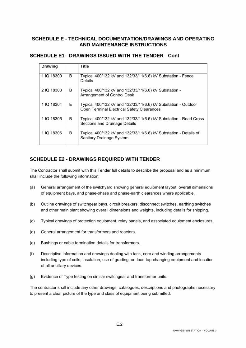
E.2 400kV GIS SUBSTATION – VOLUME 3
SCHEDULE E - TECHNICAL DOCUMENTATION/DRAWINGS AND OPERATING AND MAINTENANCE INSTRUCTIONS
SCHEDULE E1 - DRAWINGS ISSUED WITH THE TENDER - Cont
Drawing
Title
1 IQ 18300 B Typical 400/132 kV and 132/33/11(6.6) kV Substation - Fence Details
2 IQ 18303 B Typical 400/132 kV and 132/33/11(6.6) kV Substation - Arrangement of Control Desk
1 IQ 18304 E Typical 400/132 kV and 132/33/11(6.6) kV Substation - Outdoor
Open Terminal Electrical Safety Clearances 1 IQ 18305 B Typical 400/132 kV and 132/33/11(6.6) kV Substation - Road Cross
Sections and Drainage Details 1 IQ 18306 B Typical 400/132 kV and 132/33/11(6.6) kV Substation - Details of
Sanitary Drainage System
SCHEDULE E2 - DRAWINGS REQUIRED WITH TENDER
The Contractor shall submit with this Tender full details to describe the proposal and as a minimum shall include the following information:
(a) General arrangement of the switchyard showing general equipment layout, overall dimensions of equipment bays, and phase-phase and phase-earth clearances where applicable.
(b) Outline drawings of switchgear bays, circuit breakers, disconnect switches, earthing switches and other main plant showing overall dimensions and weights, including details for shipping.
(c) Typical drawings of protection equipment, relay panels, and associated equipment enclosures
(d) General arrangement for transformers and reactors.
(e) Bushings or cable termination details for transformers.
(f) Descriptive information and drawings dealing with tank, core and winding arrangements including type of coils, insulation, use of grading, on-load tap-changing equipment and location of all ancillary devices.
(g) Evidence of Type testing on similar switchgear and transformer units.
The contractor shall include any other drawings, catalogues, descriptions and photographs necessary to present a clear picture of the type and class of equipment being submitted.

E.3 400kV GIS SUBSTATION – VOLUME 3
SCHEDULE E - TECHNICAL DOCUMENTATION/DRAWINGS AND OPERATING AND MAINTENANCE INSTRUCTIONS - CONT
SCHEDULE E3 - CONTRACT DRAWING REQUIREMENTS
Following award of Contract the Contractor shall submit for approval drawings, which shall be in sufficient detail to show:
1 Substation General Arrangement and Single Line Diagrams
(a) General arrangement at each substation. (These drawings shall give the principal dimensions and positions of the circuit breakers, disconnecting switches, etc.)
(b) Single line diagram of the main high-voltage connections, showing protection and metering circuits.
2 Switchgear and Associated Control and Protection
(a) Section drawings of circuit breakers showing general details of construction.
(b) General arrangement of control and indicating panels.
(c) General arrangement of relay panels.
(d) Typical diagrams of unit protective equipment and busbar zone protection.
(e) General arrangement of battery charging equipment.
(f) General arrangement of auxiliary switchgear.
(g) General arrangement, details and schematic diagram of oil filtering and storage equipment (if any are required).
(h) General arrangement and details of isolating switches and earthing blades.
(j) General arrangement, details and schematic diagram of compressed air system, if required.
(k) Details of bushing, post and suspension insulators.
(m) General arrangement and details of surge arresters and associated surge counters.
(n) Sectional elevation drawings of each type of circuit breaker bay showing positions of current transformers and other apparatus forming an integral part of each unit.
(p) Details and schematic diagram of interlocking.
(q) Complete schematic diagrams of:
(i) Direct current tripping connections;

E.4 400kV GIS SUBSTATION – VOLUME 3
SCHEDULE E - TECHNICAL DOCUMENTATION/DRAWINGS AND OPERATING AND MAINTENANCE INSTRUCTIONS - CONT
SCHEDULE E3 - CONTRACT DRAWING REQUIREMENTS – Cont
(ii) Direct current control and indication connections;
(iii) Current transformer connections;
(iv) AC voltage connections for protective equipment, indication and synchronizing;
(v) Connections of electrical interlocking equipment;
(vi) Connections of busbar zone protective equipment.
(r) Complete wiring diagrams.
(s) Details of protective relays, accessories and current transformers including particulars of wiring and drilling dimensions.
(t) Details and arrangements of auxiliary plant and kiosks.
(u) Details of circuit breakers handling equipments.
(v) Details of instrument scales.
(w) Material lists.
(y) Layout and schedule of multi-conductor cables.
(z) Details of transformer fire protection equipment (if any are required).
3 Transformers
(a) The general arrangement and dimensions of the equipment to be supplied under the Contract.
(b) Detail drawings showing core clamping, winding arrangements, tank and wheel detail dimensions, cooler details and control cubicle details.
(c) The weight of each part on all detail drawings.
(d) The nature of the material from which the various parts are to be made and their surface finishes.
(e) The weld details and machining and assembly tolerance of all assemblies.
(f) The manner in which such parts are designed to function.
(g) Name plate details.
(h) Wiring diagrams and catalogue numbers of all electrical equipment.

E.5 400kV GIS SUBSTATION – VOLUME 3
SCHEDULE E - TECHNICAL DOCUMENTATION/DRAWINGS AND OPERATING AND MAINTENANCE INSTRUCTIONS - CONT
SCHEDULE E3 - CONTRACT DRAWING REQUIREMENTS – Cont
(j) Complete electrical wiring diagrams.
(k) Complete electrical wiring diagrams.
(m) Material lists of all ancillary equipment - starters, fans, relays, bushings etc.
(n) The location of checks, anchors, grout pockets and the like in structures constructed by others. Such drawings shall be provided not less than six months prior to the scheduled start of construction of the structure effected.
(p) Final issues of all applicable drawings
(q) Drawings, submitted by the Contractor shall be in sufficient detail to show:
(i) The general arrangement and dimensions of the parts and the size of each major part of the equipment to be supplied under the contract.
(ii) The weight of each major part on all detail drawings. The shipping weight and dimensions shall also be given.
(iii) The nature of the material and surface finish from which the various parts are to be made.
(iv) The weld details and machining and assembly tolerance of all assemblies.
(v) The manner in which such parts are designed to function.
(vi) Wiring diagrams and catalogue numbers of all electrical equipment
4 Civil, architectural and building services
Submittals required for are required to fully detail all substation buildings, roads, drainage equipment foundations building serves and air conditioning equipment as specified.
SCHEDULE E4 - CONTRACTOR’S SUBMITTALS - DRAWING AND DESIGN DATA
The Contractor shall submit all drawings, samples and models for approval in sufficient time to permit modifications to be made if such are deemed necessary, and the drawings and samples and models to be re-submitted without delaying the initial deliveries or completion of the Contract Works. The time allowed for the Employer to review and comment on drawings, samples and models shall be agreed.
If the Contractor requires early review of any drawing in order to avoid delay in the completion of the Contract Works, he shall advise the Engineer to such effect when submitting the drawing.

E.6 400kV GIS SUBSTATION – VOLUME 3
SCHEDULE E - TECHNICAL DOCUMENTATION/DRAWINGS AND OPERATING AND MAINTENANCE INSTRUCTIONS - CONT
SCHEDULE E4 - CONTRACTOR’S SUBMITTALS - DRAWING AND DESIGN DATA - Cont
The drawing format and the indexing system will be agreed at the first Contract meeting between the Contractor and the Engineer. The number of copies of each drawing or of any subsequent revision to be submitted to the Engineer for review shall be advised to the Contractor by the Engineer.
Drawings, samples and models submitted by the Contractor and approved by the Engineer shall not be departed from without the instruction in writing of the Engineer.
The Engineer reserves the right to request any further additional information that may be considered necessary in order fully to review the Contractor’s drawings.
Any drawing modified from a previously submitted drawing shall bear a new version number. Revised drawings reissued for review shall have at least one copy clearly marked indicating the amendments to the drawing. Revision boxes must be provided giving the date, revision letter and brief description of each drawing.
Any drawing or document submitted for information only shall be indicated as such by the Contractor. Drawings submitted for information only will not be returned to the Contractor unless the Engineer considers that such drawings do need to be reviewed, in which case they will be returned suitably stamped with comments.
Following final review, further copies of the reviewed drawing shall be marked “Issued for Construction” and shall be supplied to the Engineer for distribution and to Site.
All drawings shall be drawn to one of the preferred scales quoted in Table 7 of BS Publication PD6031 and on paper of the appropriate size from the International Series of A sizes.
Except as otherwise specifically approved, all drawings shall be of size not greater than A0 (normally 841 mm x 1189 mm) nor smaller than A4 (normally 210 mm x 297 mm).
All drawings shall be accurately drawn to scale on sheets of specified size and shall be legible. Wording on drawings shall be in English. All units and dimensions shall be in the metric (S.I) system. Symbols shall be in accordance with approved standards. Drawings submitted for approval shall be to scale not less than 1:20. All important dimensions shall be given and the material of which each part is to be constructed shall be indicated.
The Contractor shall be responsible for any discrepancies or errors in or omissions from the drawings, whether such drawings have been approved or not by the Engineer. Approval given by the Engineer to any drawing or sample shall neither relieve the Contractor from his liability to complete the Contract Works in accordance with this Specification and the Conditions of Contract nor exonerate him from any of his guarantees, or relieve the Contractor of responsibility for correctness, nor for results arising from errors or omissions nor for failure in the matter of guarantee, which may become evident during erection or subsequent operation.

E.7 400kV GIS SUBSTATION – VOLUME 3
SCHEDULE E - TECHNICAL DOCUMENTATION/DRAWINGS AND OPERATING AND MAINTENANCE INSTRUCTIONS - CONT
SCHEDULE E4 - CONTRACTOR’S SUBMITTALS - DRAWING AND DESIGN DATA - Cont
All drawings, samples and models shall be submitted in accordance with the provisions of this Specification and shall become the property of the Employer.
If revisions are required after a drawing has been submitted, the Contractor shall resubmit the specified number of reproductions to the Engineer.
All drawings submitted by the Contractor shall have the following particulars in the lower right hand corner in addition to the Contractor’s name, date, scale, number and title of the drawing, contract number, substation title and equipment description.
Ministry of Electricity
Baghdad, Iraq
SCHEDULE E5 - INSTALLATION AND MAINTENANCE INSTRUCTIONS
The Contract Price shall be deemed to include illustrated installation and maintenance instructions written in English.
The instructions are to be as simple and clear as possible, fully illustrated with drawings and diagrams as necessary and detailed with part numbers for ordering of replacements. Two copies are required for use of the Engineer during erection work.
A further 6 copies are to be reproduced as a book or books of approximately A4 size and bound into strong black durable imitation leather covers inscribed upon the front generally in the form of the title page to this document except that the references to Specification, Conditions of Contract, drawings, etc, will be replaced by “Installation and Maintenance Instructions”.
The name of the main Contractor, but not that of any subcontractor, may also be inscribed upon the cover after the description of the plant. The name of the Ministry of Electricity shall be inscribed upon the spine.
SCHEDULE E6 - FINAL RECORDS
After completion of work on Site all Contract drawings shall be revised where necessary to show the equipment as installed and two copies of revised drawings shall be submitted for review. A complete set of reviewed records shall be provided comprising, one full size reproducible copy and one full size print. Record drawings shall be endorsed “As Constructed” and shall be correctly titled and carry the Engineer’s review number, Contractor’s drawing number and where appropriate the Ministry of Electricity’s number allocated to the item.

E.8 400kV GIS SUBSTATION – VOLUME 3
SCHEDULE E - TECHNICAL DOCUMENTATION/DRAWINGS AND OPERATING AND MAINTENANCE INSTRUCTIONS - CONT
SCHEDULE E6 - FINAL RECORDS - Cont
After final review of the “As Constructed” record drawings the Contractor shall submit two complete sets of records on compact discs, one of which is for the Ministry of Electricity. Electronic copies of the drawings shall be in CAD 2002 format suitable for reproduction on paper using the Engineer’s preferred software packages. Each disc shall provide a comprehensive drawing list containing the drawing number, sheet, revision and title of every drawing. Each single file drawing record shall be self-supporting, complete with unique title and drawing number, without referencing other files. Non-standard items such as fonts, line types, etc should not be used. If compression techniques are applied to files then any software necessary to decompress the files shall be included on the discs. The Contractor shall ensure that all information contained on the discs has been checked for virus contamination. Each compact disc shall be supplied suitably encased and accompanied with printed documentation describing the contents of the compact discs, the formats and software used to compile the discs and the print hardware required to reproduce the record drawings.
Final record copies shall be handed over before the issue of the Taking Over Certificate.


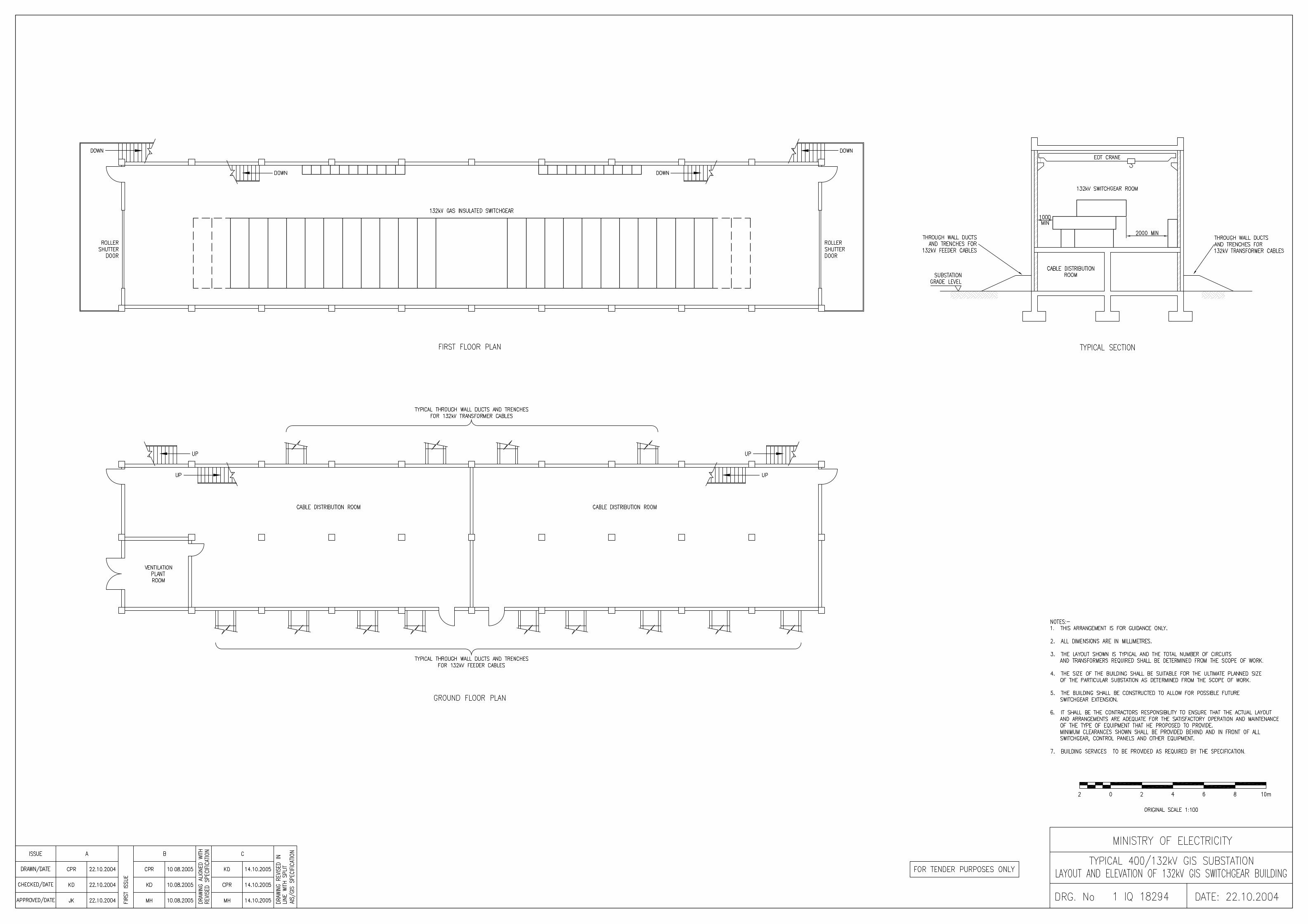


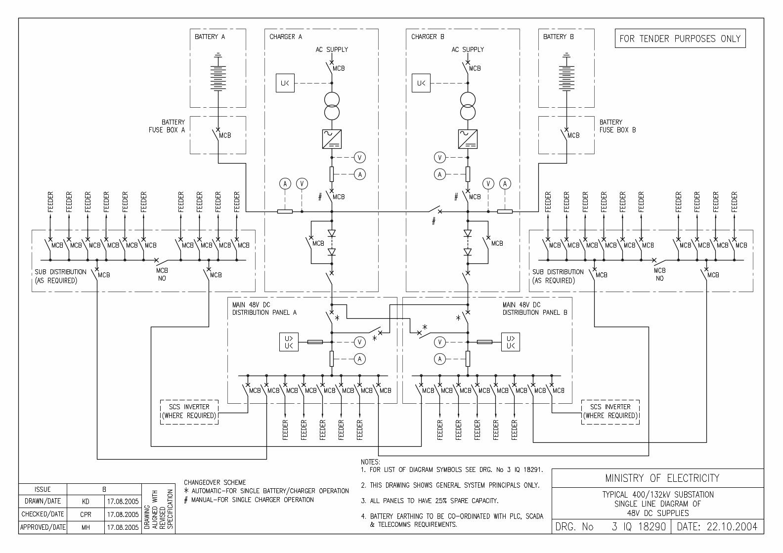


400kV GIS SUBSTATION – VOLUME 3
SCHEDULE F
DEVIATIONS FROM THE TECHNICAL SPECIFICATION

F.1 400kV GIS SUBSTATION – VOLUME 3
SCHEDULE F - DEVIATIONS FROM THE TECHNICAL SPECIFICATION
(Information to be provided with Tender) The Tenderer shall set out below a tabulated statement showing clearly section by section compliance and departures from the Specification and details of alternative proposals. The Tenderer will be deemed to have complied with the Specification in all respects and as written unless qualified in this Schedule.
Section Departure from the requirements of the Project Specification
with details of alternative proposals

400kV GIS SUBSTATION – VOLUME 3
SCHEDULE G
QUANTITIES AND PRICES
G.1 400kV GIS SUBSTATION – VOLUME 3
SCHEDULE G – QUANTITIES AND PRICES
PREAMBLE
The prices inserted in Schedule G shall include all the requirements in the Invitation to Tender. The quantities, rates and prices in Schedule G shall include all design, testing, inspection, plant, labour, supervision, materials, erection, maintenance, transportation, handling, storage, supply and use of Contractor’s equipment, temporary works, insurance, profit; together with all general risks, liabilities and obligations set out or implied in the Contract.
The cost of items against which the Tenderer has failed to enter a price shall be deemed to be covered in the Tender price. The whole cost of complying with the provisions of the Invitation to Tender shall be included in the items provided in Schedule G and where no items are provided, shall be deemed to be distributed among the rates and prices for related items of work.

G.2 400kV GIS SUBSTATION – VOLUME 3
SCHEDULE G - QUANTITIES AND PRICING - CONT
(Information to be provided with Tender)
This Schedule shall be completed for the Proposal as per the Specifications
Item no.
Description
Qty
Supply, delivery and insurance to
site
Installation, commissioning
and insurance at site
Total Price

400kV GIS SUBSTATION – VOLUME 3
SCHEDULE J1
RECOMMENDED SPARES

J1.1 400kV GIS SUBSTATION – VOLUME 3
SCHEDULE J1 - RECOMMENDED SPARES
(Information to be provided with Tender) The Tenderer is required to provide a list of recommended spares for a 5-year period from the end of the Defect Liability Period for the Work. All unit prices quoted shall be valid for any spare parts ordered by the Client in this period.
Main equipment type Part no/description Quantity Unit price

400kV GIS SUBSTATION – VOLUME 3
SCHEDULE J2
SPECIAL TOOLS, TEST EQUIPMENT

J2.1 400kV GIS SUBSTATION – VOLUME 3
SCHEDULE J2 - SPECIAL TOOLS, TEST EQUIPMENT
(Information to be provided with Tender)
Details of all special tools and test equipment required should also be provided. All unit prices quoted shall be valid for tools and test equipment ordered by the Client during the Contract Period.
The work to be done under this section consists of the supply, delivery to site and guarantee of all tools and equipment for operation and maintenance of the substations. All tools shall be of the best quality and of the class most suitable for working under the conditions specified. All material used in the tools and equipment shall be new. These shall include, but not necessarily be limited to, the items listed in the following sections.
A lump sum shall be quoted in the Schedule of Prices for all Tools and Equipment, except where separate prices are specifically requested.
Main equipment type
Part no/description Quantity Unit price
Heavy Equipment
(a) Supply two mobile cranes with jib length and lifting capacity suitable for maintenance of all switchgear equipment; in the substation. Provide an optional separate price for this equipment.
(b) Supply two mobile aerial buckets, suitable for inspection and washing of 400 kV substation insulators. Provide an optional separate price for this equipment.
(c) Supply one mobile oil filter plant, suitable for filtration of the main 400 kV transformer oil. Provide an optional separate price for this equipment.
(d) At each substation, supply one set of jacking devices suitable for use in installation or removal of the main system transformers as applicable
(e) Supply one mobile SF6 Gas Handling Plant
Workshop Equipment
(a) Steel work benches, approximately 10 square metres of working surface.
(b) Distilled water plant.

J2.2 400kV GIS SUBSTATION – VOLUME 3
SCHEDULE J2 - SPECIAL TOOLS, TEST EQUIPMENT - CONT
Main equipment type
Part no/description Quantity Unit price
(c) Drill Press complete with 2 sets of assorted drills.
(d) Bench Grinder, fine and coarse wheels, complete with spare wheels.
(e) Electric Welder, complete with assorted rods.
(f) Moisture absorbing material drying oven
Industrial vacuum cleaner.
(g) Tool racks and boxes as required.
(h) Assorted slings and lifting tackle.
(j) Vices.
Hand Tools
(a) Two sets of flat spanners, in sixes suitable for the equipment supplied.
(b) Two sets of socket spanners, in sizes suitable for the equipment supplied.
(c) Inspection lamps.
(d) Assorted screwdrivers.
(e) Electricians knives.
(f) Hammers
(g) Hacksaws.
(h) Pliers.
(j) Files
(k) Blow torch
(l) Soldering Iron.
(m) One set of taps and dies, in sizes suitable for the equipment supplied.
Special Tools
(a) Earthing and Safety Equipment
(b) 4 sets - 132 kV insulated earthing rods,

J2.3 400kV GIS SUBSTATION – VOLUME 3
SCHEDULE J2 - SPECIAL TOOLS, TEST EQUIPMENT - CONT
Main equipment type
Part no/description Quantity Unit price
(c) 2 sets - 11 kV insulated earthing rods,
(d) Earthing connections with suitable clamps
(e) One - 132 kV neon indicator,
(f) One - 11 kV neon indicator
(g) One - 33 kV neon indicator.
(h) 2 pairs - Rubber gloves.
(j) 6 - Safety hats,
(k) 6- pairs -. Safety glasses
(l) 2 - Lineman's safety belts
(m) 50 - Warning plates.
(n) 4 - First aid kits.
(p) Sufficient length of white rope to rope off two maintenance areas in the substation.
Test Equipment
(a) One set of Oil Testing Equipment, suitable for sample testing of transformer, reactor and circuit breaker oils.
(b) One AV Primary injection test set
(c) One 5000 Volt, motor-driven Megger insulation tester.
(d) One set of Meters to cover all types of substation maintenance (V meter, Ammeter, W meter, AC and DC).
(e) One AC Secondary injection test set.
(f) One Double Beam oscilloscope, complete with trolley.
(g) Two AVO multimeters, in ever-ready cases.
(h) One 50 C Volt hand driven Megger insulation tester.

J2.4 400kV GIS SUBSTATION – VOLUME 3
SCHEDULE J2 - SPECIAL TOOLS, TEST EQUIPMENT - CONT
Main equipment type
Part no/description Quantity Unit price
(i) One 1000 Volt hand-driven Megger insulation tester.
(k) Test equipment for protection with necessary transformers, wires, tools, etc.

400kV GIS SUBSTATION – VOLUME 3
SCHEDULE J3
TRANSFORMERS AND REACTORS QUANTITIES AND PRICES FOR SPARE PARTS

J3.1 400kV GIS SUBSTATION – VOLUME 3
SCHEDULE J3 - TRANSFORMERS AND REACTORS QUANTITIES AND PRICES FOR SPARE PARTS
This Schedule shall be completed by the Tenderer. Each Tenderer shall in addition to the specified spares, provide details of additional items recommended by him. These items are optional and shall only be included in the definite work on written instructions from the Engineer.
Description Recommended Number for 10 year maintenance period
Price
Autotransformers
400 kV bushings
132 kV bushings
Neutral Air/oil bushings
Set of autotransformer gaskets, complete (400MVA transformer)
Fans with motors, complete
Gas/oil relay (main unit) if similar type otherwise one of each type.
Gas/oil relay (tap changer) if similar type otherwise one of each type.
Oil level gauges if similar type otherwise one of each type.
Oil temperature indicator if similar type otherwise one of each type.
Winding temperature indicators if similar type otherwise one of each type.
Dehydrating breathers
Set of tap changer spares: details of spares offered including diverter switch, motor drive etc to be specified.
Tap position indicators
AVC relay
Fan motor protection relays
Pressure relief device

J3.2 400kV GIS SUBSTATION – VOLUME 3
SCHEDULE J3 - TRANSFORMERS AND REACTORS QUANTITIES AND PRICES FOR SPARE PARTS - CONT
Description Recommended Number for 10 year maintenance period
Price
Contactors of each type
MCBs complete with bases and holders of each rating
Cubicle heaters
Thermostats
400 kV Reactor
400 kV bushings
Sets of shunt reactor gaskets complete
Gas/oil relay
Oil level gauge
Silicon gel breather
Oil temperature indicator
Earthing Transformers
Set of gaskets, complete
Gas/oil relay
Pressure relief device

400kV GIS SUBSTATION – VOLUME 3
SCHEDULE K
BUILDING SERVICES

K.1 400kV GIS SUBSTATION – VOLUME 3
SCHEDULE K - BUILDING SERVICES
The Tenderer is to provide the name of the Manufacturer on this sheet against the item of Plant/Equipment to be provided; and provide full details of the Plant/Equipment appended to the Tender.
DATA BUILDING SERVICES
Required Offered 1 LIGHTING AND SMALL POWER
1.1 Distribution Boards:
1.2 Main Switches:
1.3 Luminaires Type / Weather proof outside
1.4 Luminaires Type / For emergency lighting
1.5 Luminaires Type / Explosion proof for battery room
1.6 Columns:
1.7 Earthing and Bonding Materials:
2 FIRE DETECTION SYSTEM
3 FIRE FIGHTING SYSTEM
3.1 Portable Extinguisher CO2 type
3.2 Portable Extinguisher, Dry powder type
3.3 Mobile Extinguisher, Foam Type (Outdoor)

400kV GIS SUBSTATION – VOLUME 3
SCHEDULE L
HEATING, VENTILATION AND AIR CONDITIONING

L.1 400kV GIS SUBSTATION – VOLUME 3
SCHEDULE L - HEATING, VENTILATION AND AIR CONDITIONING
The Tenderer is to provide the name of the Manufacturer on this sheet against the item of Plant/Equipment to be provided; and provide full details of the Plant/Equipment appended to the Tender.
DATA HEATING, VENTILATION AND AIR CONDITIONING
Required Offered
1 Split unit air conditioning
2 Battery room axial flow fans
3 Twin fan toilet extract units
4 Switchgear room supply and extract ventilation for high ambient temperature control
5 Switchgear room fresh air supply over pressurization unit
6 Extraction fans
7 Low velocity supply, return, exhaust and fresh air duct of required thickness including all hangers, supports and required accessories
8 Insulation to sheet metal ductwork thickness and type of materials
9 Grilles and diffusers supply, return, all as described in the specification
10 Weather louvres
11 Exhaust louvres
12 Sand filters louvers factory assembled
13 Fire dampers, size, material and type
14 Volume control dampers type and material
15 Filters for fresh air intakes and ahu
16 Automatic control system complete for a/c and ventilating system including control panel

M.1 400kV GIS SUBSTATION – VOLUME 3
SCHEDULE M
GUARANTEED TRANSFORMER (AND REACTOR) LOSSES AND PENALTIES
The Tenderer shall complete the following guarantees based on highest declared rated power at Site conditions.
400/138.6/11kV, 250/250/75MVA, auto transformer (comprising 3x83.33MVA single phase units) as specified. Item Description
Unit Declared value
1 No load losses (NNL) at rated voltage ratio at IEC rating
kW
2 Load losses (LL) at 75°C and rated ONAF power and principal tapping: HV/LV winding at IEC rating
kW
3 Total losses (TL=NNL+LL) kW
250 MVAr 400kV Shunt Reactors where specified
Item Description Unit Declared value
4
No load losses (NNL) at rated voltage ratio at IEC rating
kW
5 Load losses (LL) at 75°C and rated ONAF power and principal tapping: HV/LV winding at IEC rating
kW
6 Total Reactor losses (TL=NNL+LL) kW
1. Loss Evaluation
For the purposes of tender evaluation the 400/138.6kV transformer (and where applicable the 400kV reactor) losses will be capitalized, in the following manner: Transformers No-load loss (NLL) 2932 US$/kW at rated voltage Load loss (LL) 688US$/kW at rated MVA and voltage Reactors No-load loss 2932 US$/kW at rated voltage Capitalisation (PV) Price capital value + NLL + LL

M.2 400kV GIS SUBSTATION – VOLUME 3
2. Penalties A maximum variation of +10% of the total declared losses (TL) is permitted. Any transformer or reactor with losses more than +10% of the Total Loss (TL) declared will be rejected, unless otherwise agreed by the Engineer. For transformers or reactors with total losses within +5% of the declared losses no variation of the contract price will be made. For transformers or reactors where the total losses are between +5% to +10% of the total declared losses the contract price will be reduced by the total capitalised cost of losses in excess of the capitalised cost of the declared guaranteed losses. For any transformer or reactor with total losses less than 100% of the guaranteed losses, no variation of the Contract price will be made.