MINISTRY OF ELECTRICITY - Camera di Commercio...
136
MINISTRY OF ELECTRICITY IRAQ HIGH TENSION PROJECTS 132/33/11/6.6 KV AIR INSULATED SWITCHGEAR (AIS) SUBSTATIONS VOLUME 2 CIVIL AND BUILDING WORKS, AND BUILDING SERVICES JANUARY 2007
Transcript of MINISTRY OF ELECTRICITY - Camera di Commercio...

MINISTRY OF ELECTRICITY
IRAQ HIGH TENSION PROJECTS 132/33/11/6.6 KV AIR INSULATED SWITCHGEAR (AIS) SUBSTATIONS
VOLUME 2 CIVIL AND BUILDING WORKS, AND BUILDING SERVICES JANUARY 2007

132kV AIS SUBSTATION – VOLUME 2
LIST OF REVISIONS
Current Rev.
Date Page affected
Prepared by
Checked by (technical)
Checked by (quality
assurance)
Approved by
1 2 3 4 5
22.12.04 18.03.05 Aug 05 Oct 05 Jan 07
ALL ALL ALL ALL
JKR JKR PM PM/MH PM/MH
PM PM JKR JW JW
JW JW JW JW JW
JW JW JW JW JW
REVISION HISTORY
3 Aug 05 ALL Updated with MOE comments and general alignment across volumes.
4 Oct 05 ALL Specification split into GIS and AIS versions. 5 Jan 07 ALL General review

132kV AIS SUBSTATION – VOLUME 2
CONTENT SHEET
VOLUME 1 TECHNICAL SPECIFICATION – PLANT VOLUME 2 TECHNICAL SPECIFICATION & SCHEDULES – CIVIL WORKS VOLUME 3 TECHNICAL SCHEDULES – PLANT

132kV AIS SUBSTATION – VOLUME 2
CONTENTS
Page No.
1. CIVIL............................................................................................................................. 1-1
1.1 General.................................................................................................................. 1-1
1.1.1 Scope ............................................................................................................. 1-1
1.1.2 Clearing and Site Preparation ........................................................................ 1-5
1.1.3 Excavation...................................................................................................... 1-5
1.1.4 Fill and Back Fill ............................................................................................. 1-7
1.1.5 Asphalt and Concrete Paving, Finish Grading and Reinstatement .............. 1-12
1.1.6 Building and Associated Work...................................................................... 1-14
1.1.7 Oil Containment for Transformer and Reactor Bunds, and Firewalls ........... 1-18
1.1.8 Concrete....................................................................................................... 1-19
1.1.9 Outdoor Steel Structures.............................................................................. 1-42
1.1.10 Water Supply, Drainage and Disposal ......................................................... 1-48
1.1.11 Gates and Fencing ....................................................................................... 1-50
1.2 Architectural......................................................................................................... 1-51
1.2.1 General......................................................................................................... 1-51
1.2.2 Scope of Work.............................................................................................. 1-51
1.2.3 Materials....................................................................................................... 1-52
1.2.4 Signage ........................................................................................................ 1-52
1.2.5 Masonry........................................................................................................ 1-52
1.2.6 Cement Rendering ....................................................................................... 1-53
1.2.7 Roofing ......................................................................................................... 1-54
1.2.8 Precast Concrete.......................................................................................... 1-54
1.2.9 Aluminium Windows ..................................................................................... 1-55
1.2.10 Vehicle Access Doors .................................................................................. 1-56
1.2.11 Metal Doors and Frames.............................................................................. 1-56
1.2.12 Wood Doors and Frames ............................................................................. 1-56
1.2.13 Door Hardware ............................................................................................. 1-56
1.2.14 Gypsum Plaster............................................................................................ 1-57
132kV AIS SUBSTATION – VOLUME 2
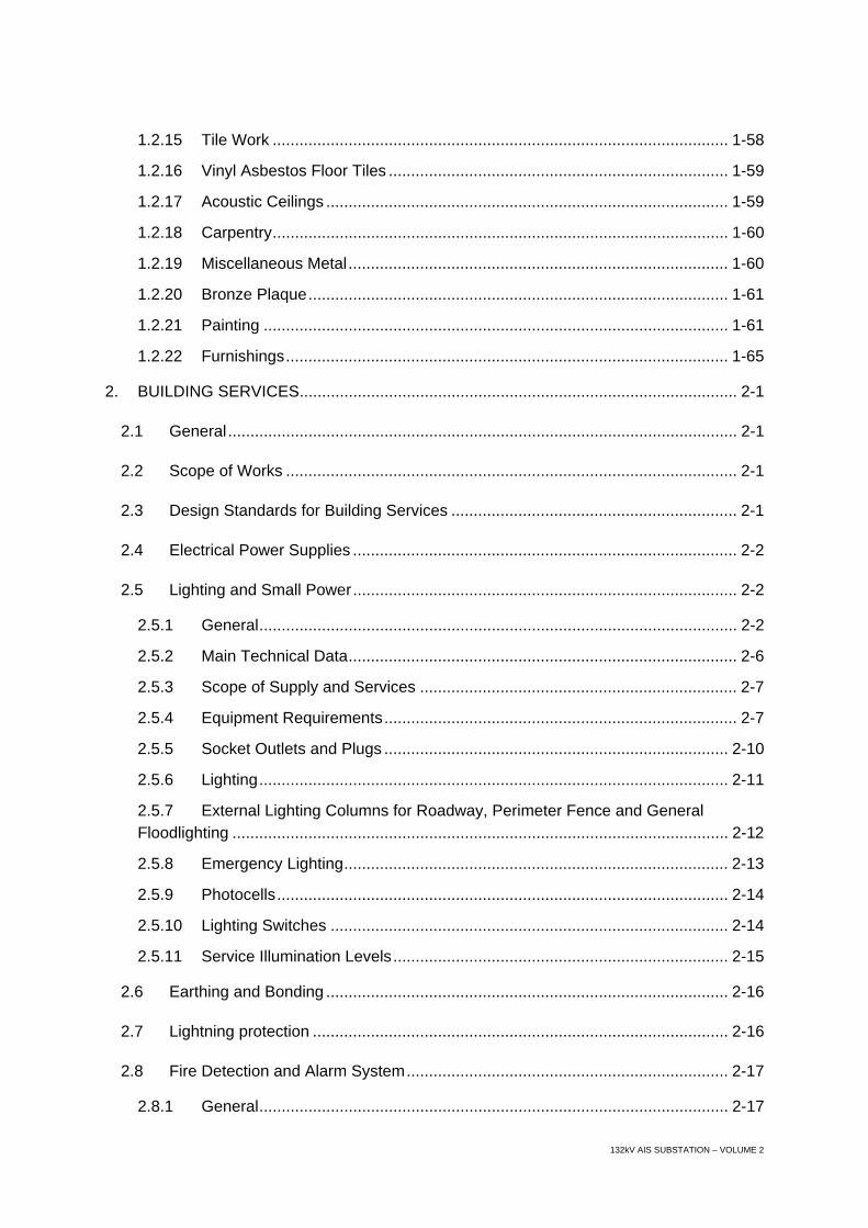
1.2.15 Tile Work ...................................................................................................... 1-58
1.2.16 Vinyl Asbestos Floor Tiles ............................................................................ 1-59
1.2.17 Acoustic Ceilings .......................................................................................... 1-59
1.2.18 Carpentry...................................................................................................... 1-60
1.2.19 Miscellaneous Metal..................................................................................... 1-60
1.2.20 Bronze Plaque.............................................................................................. 1-61
1.2.21 Painting ........................................................................................................ 1-61
1.2.22 Furnishings................................................................................................... 1-65
2. BUILDING SERVICES.................................................................................................. 2-1
2.1 General.................................................................................................................. 2-1
2.2 Scope of Works ..................................................................................................... 2-1
2.3 Design Standards for Building Services ................................................................ 2-1
2.4 Electrical Power Supplies ...................................................................................... 2-2
2.5 Lighting and Small Power...................................................................................... 2-2
2.5.1 General........................................................................................................... 2-2
2.5.2 Main Technical Data....................................................................................... 2-6
2.5.3 Scope of Supply and Services ....................................................................... 2-7
2.5.4 Equipment Requirements............................................................................... 2-7
2.5.5 Socket Outlets and Plugs ............................................................................. 2-10
2.5.6 Lighting......................................................................................................... 2-11
2.5.7 External Lighting Columns for Roadway, Perimeter Fence and General Floodlighting ............................................................................................................... 2-12
2.5.8 Emergency Lighting...................................................................................... 2-13
2.5.9 Photocells..................................................................................................... 2-14
2.5.10 Lighting Switches ......................................................................................... 2-14
2.5.11 Service Illumination Levels........................................................................... 2-15
2.6 Earthing and Bonding .......................................................................................... 2-16
2.7 Lightning protection ............................................................................................. 2-16
2.8 Fire Detection and Alarm System........................................................................ 2-17
2.8.1 General......................................................................................................... 2-17
132kV AIS SUBSTATION – VOLUME 2
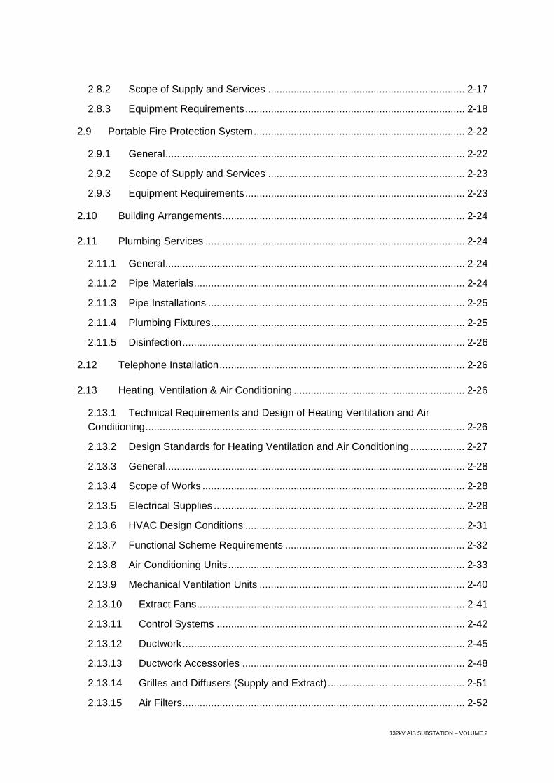
2.8.2 Scope of Supply and Services ..................................................................... 2-17
2.8.3 Equipment Requirements............................................................................. 2-18
2.9 Portable Fire Protection System.......................................................................... 2-22
2.9.1 General......................................................................................................... 2-22
2.9.2 Scope of Supply and Services ..................................................................... 2-23
2.9.3 Equipment Requirements............................................................................. 2-23
2.10 Building Arrangements..................................................................................... 2-24
2.11 Plumbing Services ........................................................................................... 2-24
2.11.1 General......................................................................................................... 2-24
2.11.2 Pipe Materials............................................................................................... 2-24
2.11.3 Pipe Installations .......................................................................................... 2-25
2.11.4 Plumbing Fixtures......................................................................................... 2-25
2.11.5 Disinfection................................................................................................... 2-26
2.12 Telephone Installation...................................................................................... 2-26
2.13 Heating, Ventilation & Air Conditioning ............................................................ 2-26
2.13.1 Technical Requirements and Design of Heating Ventilation and Air Conditioning................................................................................................................ 2-26
2.13.2 Design Standards for Heating Ventilation and Air Conditioning ................... 2-27
2.13.3 General......................................................................................................... 2-28
2.13.4 Scope of Works ............................................................................................ 2-28
2.13.5 Electrical Supplies ........................................................................................ 2-28
2.13.6 HVAC Design Conditions ............................................................................. 2-31
2.13.7 Functional Scheme Requirements ............................................................... 2-32
2.13.8 Air Conditioning Units................................................................................... 2-33
2.13.9 Mechanical Ventilation Units ........................................................................ 2-40
2.13.10 Extract Fans.............................................................................................. 2-41
2.13.11 Control Systems ....................................................................................... 2-42
2.13.12 Ductwork................................................................................................... 2-45
2.13.13 Ductwork Accessories .............................................................................. 2-48
2.13.14 Grilles and Diffusers (Supply and Extract) ................................................ 2-51
2.13.15 Air Filters................................................................................................... 2-52

132kV AIS SUBSTATION – VOLUME 2
2.13.16 External Louvres....................................................................................... 2-52
2.13.17 Instruments & Detectors ........................................................................... 2-53
2.13.18 Insulation Work ......................................................................................... 2-53
2.13.19 Civil & Builders Work ................................................................................ 2-55
2.13.20 Construction Standards ............................................................................ 2-55
2.13.21 Equipment Approvals................................................................................ 2-55
2.13.22 Product Selection...................................................................................... 2-55
2.13.23 Product Handling & Storage ..................................................................... 2-56
2.13.24 Noise Levels ............................................................................................. 2-57
2.13.25 Positioning Of Plant .................................................................................. 2-57
2.13.26 Foundation Bolts & Alignment .................................................................. 2-57
2.13.27 Plant Bases & Anti-Vibration Mountings ................................................... 2-57
2.13.28 Connection of Equipment ......................................................................... 2-58
2.13.29 Cutting and Drilling of Structural Frames, etc. .......................................... 2-58
2.13.30 Machine Guards ....................................................................................... 2-58
2.13.31 Painting & Identification ............................................................................ 2-58
2.14 Inspection and Tests........................................................................................ 2-59
2.14.1 Building Electrical Services .......................................................................... 2-59
2.14.2 Heating Ventilation and Air Conditioning System......................................... 2-60
2.15 Special Equipment and Tools .......................................................................... 2-61
2.16 Spare Parts ...................................................................................................... 2-61
2.17 Packaging, Shipping and Transport................................................................. 2-61
2.18 Training ............................................................................................................ 2-61
2.19 Documentation................................................................................................. 2-62
2.19.1 Documentation With Tender......................................................................... 2-62
2.19.2 Documentation after Award of Contract ....................................................... 2-63
2.20 Handover ......................................................................................................... 2-64
1-1 132kV AIS SUBSTATION – VOLUME 2
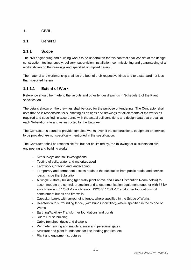
1. CIVIL
1.1 General
1.1.1 Scope The civil engineering and building works to be undertaken for this contract shall consist of the design, construction, testing, supply, delivery, supervision, installation, commissioning and guaranteeing of all works shown on the drawings and specified or implied herein.
The material and workmanship shall be the best of their respective kinds and to a standard not less than specified herein.
1.1.1.1 Extent of Work Reference should be made to the layouts and other tender drawings in Schedule E of the Plant specification.
The details shown on the drawings shall be used for the purpose of tendering. The Contractor shall note that he is responsible for submitting all designs and drawings for all elements of the works as required and specified, in accordance with the actual soil conditions and design data that prevail at each Substation site and as instructed by the Engineer.
The Contractor is bound to provide complete works, even if the constructions, equipment or services to be provided are not specifically mentioned in the specification.
The Contractor shall be responsible for, but not be limited by, the following for all substation civil engineering and building works:
- Site surveys and soil investigations - Testing of soils, water and materials used - Earthworks, grading and landscaping - Temporary and permanent access roads to the substation from public roads, and service
roads inside the Substation - A Single 2-storey building (generally plant above and Cable Distribution Room below) to
accommodate the control, protection and telecommunication equipment together with 33 kV switchgear and 11/6.6kV switchgear - 132/33/11/6.6kV Transformer foundations, oil containment bunds and fire walls
- Capacitor banks with surrounding fence, where specified in the Scope of Works - Reactors with surrounding fence, (with bunds if oil filled), where specified in the Scope of
Works - Earthing/Auxiliary Transformer foundations and bunds - Guard House building - Cable trenches, ducts and drawpits - Perimeter fencing and matching main and personnel gates - Structure and plant foundations for line landing gantries, etc - Plant and equipment structures

1-2 132kV AIS SUBSTATION – VOLUME 2
- Roads, footpaths and surface chippings - Foul and surface water drainage systems, and septic tank - Heating, Ventilation and Air Conditioning - Building Services - plumbing, water, small power and lighting, telephones, fire detection, etc - Water tanks - Temporary works - Design, preparation of detailed construction drawings, bar bending schedules and all
drawings and documents necessary for, completion and maintenance of the works, - Preparation of As-built documentation - 132 kV switchyard to accommodate the 132 kV AIS switchgear - 132 kV switchgear structure and plant foundations - 132 kV switchgear structures - Any other works required to complete the substation and put it into operation
1.1.1.2 Standards and Design Criteria Except where otherwise specified, implied or otherwise agreed in the Contract, the design, and the specification of materials and workmanship shall comply in all respects with the requirements of the latest applicable British Standards (hereafter referred to as B.S.). Other international Standards which meet or exceed the requirements of the appropriate British Standard may be used subject to the prior agreement of the Engineer.
The Contractor shall submit all design calculations to the Engineer for his approval prior to the commencement of preparation of working and shop drawings. After the Engineer has approved the calculations, the Contractor shall prepare all necessary working and shop drawings and submit same for approval by the Engineer, as specified under the “Submittal” Section of the Specifications.
1.1.1.3 Design Loading (a) Dead and live loading
BS 6399 – Loadings for Buildings shall be used to determine all dead and imposed loads amended only as follows. Snow loading shall be considered if appropriate. Roofs without access should be designed for a sand loading of 1 kN/m2, and where access is provided it should be designed for a loading of 1.50 kN/m2
(b) Wind loading
Wind loadings as determined in CP3 Chapter V plus all amendments, shall be applied to all buildings and structures. Although CP3 is a superseded document it may be used for reference in this case. In determining Vs in the code for wind loading, basic wind speed of 40 m/s equivalent to V of 34.2 m/s 12 m above GL, at 15 degrees C, should be used and factors S1 and S3 should be taken as unity. Factor S2 should be determined from Table 3 in Part 2 of the Code surface category 1 - “Open country with no obstruction”.
(c) Seismic loading
All structures including buildings and their foundations shall be designed for seismic events as defined in the “Uniform Building Code” Zone 3.
1-3 132kV AIS SUBSTATION – VOLUME 2
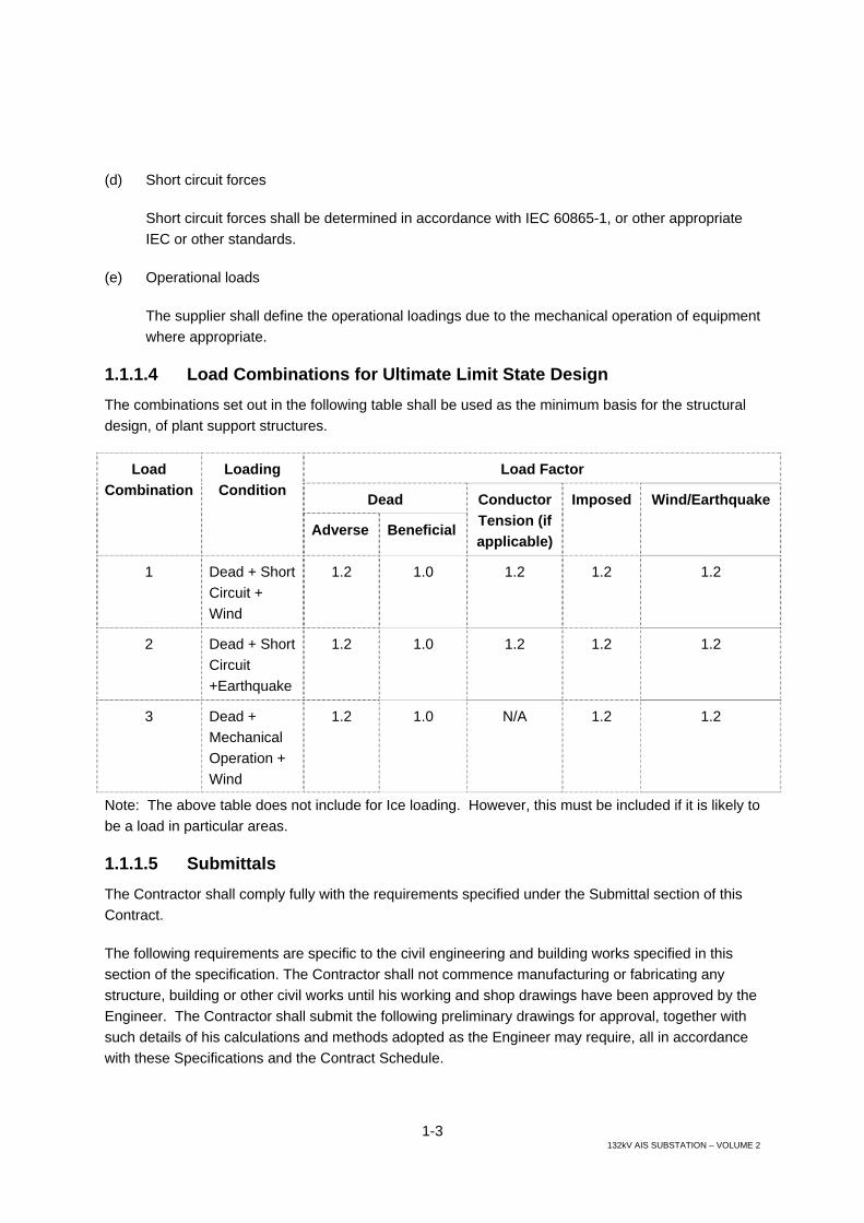
(d) Short circuit forces
Short circuit forces shall be determined in accordance with IEC 60865-1, or other appropriate IEC or other standards.
(e) Operational loads
The supplier shall define the operational loadings due to the mechanical operation of equipment where appropriate.
1.1.1.4 Load Combinations for Ultimate Limit State Design The combinations set out in the following table shall be used as the minimum basis for the structural design, of plant support structures.
Load Factor
Dead
Load Combination
Loading Condition
Adverse Beneficial
Conductor Tension (if applicable)
Imposed Wind/Earthquake
1 Dead + Short Circuit + Wind
1.2 1.0 1.2 1.2 1.2
2 Dead + Short Circuit +Earthquake
1.2 1.0 1.2 1.2 1.2
3 Dead + Mechanical Operation + Wind
1.2 1.0 N/A 1.2 1.2
Note: The above table does not include for Ice loading. However, this must be included if it is likely to be a load in particular areas.
1.1.1.5 Submittals The Contractor shall comply fully with the requirements specified under the Submittal section of this Contract.
The following requirements are specific to the civil engineering and building works specified in this section of the specification. The Contractor shall not commence manufacturing or fabricating any structure, building or other civil works until his working and shop drawings have been approved by the Engineer. The Contractor shall submit the following preliminary drawings for approval, together with such details of his calculations and methods adopted as the Engineer may require, all in accordance with these Specifications and the Contract Schedule.

1-4 132kV AIS SUBSTATION – VOLUME 2
(a) The General Arrangement of each Substation showing the principal dimensions and positions of buildings, roads, services, switchgear buildings, transformers, etc.
(b) Drawings showing the dimensions of the principal members of all structures.
The final working and shop drawings, which shall be submitted to the Engineer, after the approval of the preliminary drawings and details of calculations specified above, shall be in sufficient detail to show:
(i) The general arrangement, details and dimensions of all parts of buildings, steel structures and of all other civil works to be supplied under the Contract.
(ii) The nature of the materials from which the various parts are to be made together with their surface finish.
(iii) Weld details, machining and assembly tolerances for all assemblies.
(iv) The manner in which such parts are designed to function.
(v) Schedules of materials and details in full for all structural steel members and reinforcing bars.
(vi) Detailed arrangement of various equipments in the switchgear buildings
In addition to the above, the Contractor shall submit to the Engineer any further information that the Engineer may require to enable him to approve the final working and shop drawings. After the drawings have been approved, no changes shall be made to the drawings without the written permission of the Engineer. Changes to facilitate fabrication, to speed up delivery or to permit substitutions of material which is in short supply, may be made if approved in writing by the Engineer.
The Contractor shall furnish the Engineer with duplicate copies of certified mill test reports before fabrication is commenced on any materials covered by such reports.
Approval by the Engineer of the Contractor’s drawings shall not relieve the Contractor of responsibility for the correctness thereof, nor for the results arising from errors or omissions, nor for any faults or defects, nor for failure in the matter of guarantee, which may become evident during erection or subsequent operation.
1.1.1.6 Soil Investigations The Tenderer shall carry out whatever Soil investigations and testing deemed necessary for the proper foundation design and construction to suit the Site conditions.
No claim from the Contractor for price adjustment on account of any changes in the foundation works will be accepted under any circumstances.
1-5 132kV AIS SUBSTATION – VOLUME 2
The results and interpretation of all soil investigations, testing and calculations in respect of the soil bearing capacity values for the Site shall be submitted in Report format for approval by the Engineer before preparation of the foundation working drawings.
No working drawing will be approved by M.O.E./the Engineer until such test values have been submitted and approved.
Where necessary the Contractor shall adopt pile foundations for heavy equipments and buildings.
1.1.1.7 Topography and Finished Grade Elevation The topographical survey for the Site of the Substation is the responsibility of the Tenderer.
No extra cost shall be paid to the Contractor on account of any increase in quantity of the work to fulfil the requirement given in the tender documentation and drawings.
The site of the Substation shall be raised a minimum of +500 mm above the highest point of the existing ground level around the outside the perimeter fence, as indicated on the tender drawings. For a flooded area the site shall be raised to a level not less than the level of the nearest paved road.
1.1.2 Clearing and Site Preparation 1.1.2.1 General The work in this Section shall consist of all clearing, grubbing and stripping of the topsoil from the Site as directed by the Engineer and specified herein. The Work shall also include the transportation and disposal of all waste materials off the site to the areas arranged for by the Contractor, and to the approval of the Engineer.
1.1.2.2 Clearing and Grubbing Clearing shall include cutting and removing trees, bushes and other vegetation and removing fallen timber and other surface litter. Grubbing shall consist of digging out and removing stumps and roots remaining after the clearing operation.
1.1.2.3 Stripping of Topsoil The Contractor shall, after clearing and grubbing, strip to a minimum depth of 200 mm all topsoil or other surface deposits. If, in the opinion of the Engineer, topsoil extends to a greater depth than 200 mm, the Contractor shall remove all such soil as directed by the Engineer. The Contractor may stockpile approved topsoil for reuse as specified herein subject to the Engineer’s approval. The stripped surface should be compacted to 95% proctor dry density before the starting of the filling operations.
1.1.3 Excavation 1.1.3.1 General Excavation shall include the removal of all material of any nature including rock which interferes with the construction work.
1-6 132kV AIS SUBSTATION – VOLUME 2
The Contractor must clear all excavations of mud, loose material, dirt and debris, and if required by the Engineer, the bottom 150 mm of excavation shall not be removed until just before the commencement of construction.
All necessary safety precautions shall be taken to avoid injuries. The surfaces of excavation shall be protected at all times from erosion or collapse due to weather or other conditions. Sides of excavations shall be shored up where necessary to the satisfaction of the Engineer.
The Contractor shall at all times keep all excavations and trenches free from water. He shall use pumps, well points or any other method necessary to remove water in a manner that will prevent loss of soil and maintain stability of the sides and bottom of the excavation, all to the approval of the Engineer.
If excavations are carried beyond the lines or elevations shown on the drawings or specified herein, the Contractor shall be required to backfill such excavation with C20 concrete or crushed stone as directed by the Engineer at the Contractor’s own expenses.
The Tenderer shall investigate the water table level at the proposed Substation Site, and no extra cost on account of any difficulty arising out of a high water table will be entertained.
1.1.3.2 Excavation for Foundations The underside of all foundations shall be at a minimum depth of 200 mm below the stripped surface.
Immediately after excavation for foundations is completed and approved by the Engineer, C20 concrete 100mm, thick is to be laid as blinding for the structural concrete foundations.
1.1.3.3 Excavation for Underground Services The minimum area of excavation shall be the project plan area of the various items being installed. However, the Contractor shall make due allowance for working space that he considers necessary and also for placing the specified concrete or other bedding material as shown on the drawings. Variances in unit cost shall be based on the above.
Trenches shall be excavated to the general lines and depths specified and as shown on the drawings.
If the bottom of any trench or excavation is found to be unstable or unsatisfactory, the Contractor shall excavate such unsuitable material to the width and depth ordered by the Engineer. The sub-grade shall then be restored by back-filling with approved materials so as to provide a uniform and continuous bearing and support for the service pipe or duct.
1.1.3.4 Excavation for Roads, Switchyards and Parking Areas Any soft areas which develop during rolling, as specified herein, shall be excavated as directed by the Engineer. All loose rock or boulders and all ridge rock encountered in the excavation shall be removed.
The excavated surface shall be compacted to 95% modified proctor dry density.
1-7 132kV AIS SUBSTATION – VOLUME 2
1.1.3.5 Disposal of Excavated Materials All materials obtained from the excavations, and approved by the Engineer, for use as general backfilling materials shall be laid aside and afterwards deposited as and where directed by the Engineer.
Any materials not so approved shall be removed by the Contractor and disposed of in areas off the site arranged for by the Contractor at his own cost, and approved by the Engineer. The deposited material shall be spread and trimmed to a uniform surface.
1.1.4 Fill and Back Fill 1.1.4.1 Materials (a) General filling material
The general filling material shall consist of approved natural material obtained directly from the excavation or from borrow areas approved by the Engineer. Only material approved by the Engineer shall be used for general fill, and such material shall be free of vegetation, topsoil, roots, logs, stumps or any other organic, perishable or unsuitable material. All necessary precautions, to the approval of the Engineer, shall be taken to exclude termites from the filling material.
(b) Borrow area operations
Detailed planning of the excavation shall be the responsibility of the Contractor and shall be subject to approval by the Engineer. The Contractor shall pay particular attention to the natural water content of the material.
Prior to the commencement of the work, the Contractor shall submit for approval by the Engineer, a plan showing details of the Contractor’s proposed methods, and the sequence, and the schedule of operations in the borrow area. During construction, the plan shall be reviewed and modified as required. A copy of the modified plan and schedule shall be provided for the Engineer’s approval prior to implementation of any changes.
A system of surface drainage in the borrow area consisting of ditches and other means shall be installed to ensure that precipitation drains away from the borrow area; and that ponding and infiltration is prevented. After completion of excavations, the drainage system shall be left in such a condition that drainage of the borrow area shall continue to be effective.
All final slopes shall be trimmed to stable slopes and shall not be steeper that three horizontal to one vertical.
(c) Granular class A and class B materials
All granular materials intended for use on the work shall first be approved by the Engineer. The Contractor shall submit an analysis from an approved testing laboratory, to show that the materials conform to the specifications. If, in the opinion of the Engineer, further tests are required, then these tests shall be carried out as directed by the Engineer at the expense of the Contractor.

1-8 132kV AIS SUBSTATION – VOLUME 2
Granular class A
Fill material shall consist of crushed rock or gravel obtained from quarries, deposits of pitrun gravel, Talus rock, disintegrated granite, mine waste and slag, clinkers, cinders and other material which has a physical structure not affected by water or the elements. Materials such as shale, limestone or stratified limestone are not acceptable. The material shall contain a minimum of 30 per cent of crushed particles. Crushed particle shall have at least one surface or face formed by its fracture from a larger particle. The percentage of crushed material shall be determined by examining the fraction retained on a 5 mm mesh sieve and dividing the weight of the crushed particles by the total weight of the sample. The sizing and grading of granular Class materials shall conform to the requirements specified herein.
Granular class B
Fill material shall consist of either:
(i) gravel from bankrun material; where no crushing is required, but oversize particles shall have been removed and the physical characteristics and sizing and grading shall be according to the specification,
or
(ii) crushed rock screening; having physical characteristics in sizing and grading according to the specification.
Materials shall have a physical structure not affected by water or the elements; and materials such as shale, shaley limestone and clay will not be acceptable in any quantity whatsoever.
(d) Grading of granular fill materials
The grading of the granular Class A and Class B fill materials shall be within the following limits:
1-9 132kV AIS SUBSTATION – VOLUME 2
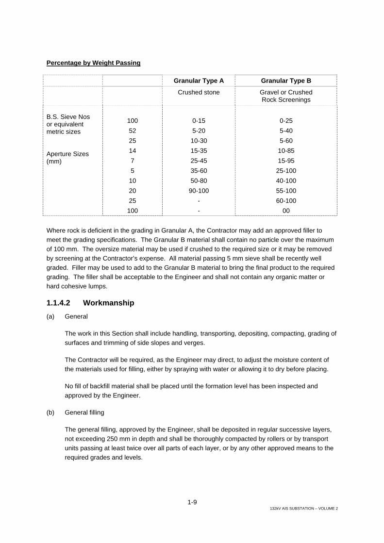
Percentage by Weight Passing
Granular Type A Granular Type B
Crushed stone Gravel or Crushed Rock Screenings
B.S. Sieve Nos or equivalent metric sizes Aperture Sizes (mm)
100 52 25 14 7 5
10 20 25 100
0-15 5-20 10-30 15-35 25-45 35-60 50-80
90-100 - -
0-25 5-40 5-60 10-85 15-95
25-100 40-100 55-100 60-100
00 Where rock is deficient in the grading in Granular A, the Contractor may add an approved filler to meet the grading specifications. The Granular B material shall contain no particle over the maximum of 100 mm. The oversize material may be used if crushed to the required size or it may be removed by screening at the Contractor’s expense. All material passing 5 mm sieve shall be recently well graded. Filler may be used to add to the Granular B material to bring the final product to the required grading. The filler shall be acceptable to the Engineer and shall not contain any organic matter or hard cohesive lumps.
1.1.4.2 Workmanship (a) General
The work in this Section shall include handling, transporting, depositing, compacting, grading of surfaces and trimming of side slopes and verges.
The Contractor will be required, as the Engineer may direct, to adjust the moisture content of the materials used for filling, either by spraying with water or allowing it to dry before placing.
No fill of backfill material shall be placed until the formation level has been inspected and approved by the Engineer.
(b) General filling
The general filling, approved by the Engineer, shall be deposited in regular successive layers, not exceeding 250 mm in depth and shall be thoroughly compacted by rollers or by transport units passing at least twice over all parts of each layer, or by any other approved means to the required grades and levels.
1-10 132kV AIS SUBSTATION – VOLUME 2
The dry density of the soil after compaction shall be at least 95% of the maximum obtainable Standard Proctor dry density measured in accordance with the requirements of B.S. 1377 or other approved standards.
The general fill shall be laid and compacted in layers as specified, until the elevation at the top of the compacted fill is 50 mm below finished grade level. The Site shall be drained properly to the satisfaction of the Engineer.
(c) Chemical treatment of soil
To prevent the ingress of termites into the works at the new Substations, soil treatment shall be carried out by the Contractors as specified below and to the entire satisfaction of the Engineer. The chemical used to treat the soil shall be of chloridine or equivalent approved by the M.O.E. Engineer.
The rate of application to the soil of the ready for use solution shall be as follows:
(i) Before casting walkways surrounding buildings, excavate perimeter trench 1.0 m deep by 500 mm wide adjacent to the external walls. Apply 6 litres/sq. metre to the excavated bottom of the trench and to each of the 250 mm compacted layers of backfill.
(ii) 6 litres/sq. metre over all building areas and associated paved walkway areas, including the outer faces of all trenches. Applications to be on top of fill below concrete slabs.
(iii) The entire Substation Site including the bermed areas outside the perimeter or boundary fence/wall shall be treated with an approved vegetation/weed killer to the complete satisfaction of the Engineer. This treatment shall be chemically compatible with the soil treatment for termites outlined above.
Once the soil has been treated, it is important that it should not subsequently be disturbed. Any areas of soil which are subsequently disturbed shall be retreated at the expense of the Contractors to the satisfaction of the Engineer.
(d) Backfilling of trenches and foundations
Class “B” material shall be used for backfilling trenches and foundations. Backfill for trenches shall be considered as starting at the top of the bedding over the pipe or conduit. Any materials below this point shall be considered as bedding. Backfill shall be placed in layers not exceeding 250 mm in thickness.
Backfill for manholes shall start at the subgrade and shall be brought up simultaneously to the same elevation on all sides of the manhole in layers not exceeding 250 mm. Except where the pipe must remain exposed for leakage tests and subject to the provisions herein, the Contractor shall proceed as soon as possible with the backfilling operations. Care shall be exercised so that the pipe will not be damaged or displaced.
1-11 132kV AIS SUBSTATION – VOLUME 2
The material shall be compacted to 95% of maximum density as determined by the modified Proctor density test. The backfill material shall not be dropped from the side of the trench so that there is a clear fall onto the partially covered pipe. Backfill material may be pushed from the filled and of the trench into the partially filled section so that it will roll down onto the covered pipe.
(e) Road foundations
Following the site strip to a minimum depth of 200 mm, described previously, the area of the Site covered by a road, switchyard or parking area and for a distance of 1 m outside these areas, shall be compacted to a dry density in the upper 500 mm of at least 95% of the maximum density as determined by the modified Proctor test. Soft areas which develop during compaction shall be removed and replaced at the Contractor’s expense with approved fill material. When completed the formation shall be smooth and free from ridges, cracks or loose material.
The base and sub-base courses shall be approved granular materials B and A, respectively to thicknesses shown on the drawings. They shall be placed inlayers, such that, after compaction, the thickness of each layer does not exceed 100 mm.
Each layer shall be compacted to obtain 95% modified Proctor density before proceeding to apply a subsequent layer. Compaction shall be performed with a wobbly wheel roller or an equivalent vibratory roller, as approved by the Engineer. The rolling shall be done longitudinally, commencing at the edge and overlapping each run until the centre line is reached. The rolling shall continue until satisfactory compaction is obtained. On sections inaccessible for the larger equipment, the compaction shall be obtained using approved mechanical vibratory equipment. The compaction requirements shall be the same as for the rest of the base.
Any irregularities or depressions which develop from the rolling shall be corrected by loosening, adding or removal of material and re-rolling until the surface is smooth and uniform.
The layer of material shall be bladed to the shape of the required crown and the material shall be sprinkled with water to aid compaction and/or reduce dust nuisance. When used to aid compaction, water shall be applied immediately ahead of the compaction equipment. The amount of water added shall be controlled so that the optimum moisture content of the material is not exceeded.
After the final course is laid, giving the required overall thickness, the surface shall be shaped by grading and rolling to produce a surface of required crown and contour. The tolerance permitted in the surface shall be determined by placing a 3 m straight edge, transversely or longitudinally, on any section. The final surface of the base material shall be irregularities no more than 6 mm in the 3 m length.
The final surface of the sub-base material shall have irregularities of no more than 15 mm.

1-12 132kV AIS SUBSTATION – VOLUME 2
1.1.5 Asphalt and Concrete Paving, Finish Grading and Reinstatement 1.1.5.1 General The work of this Section consists of paving roads and parking areas, general surfacing and surface grading, kerbs and paving slabs. The work shall include supply of all materials placed and compacted as specified herein, all to the satisfaction of the Engineer.
Roads shall be finished with hot rolled asphalt bituminous base and wearing courses, except where fuel spillage may occur where suitable concrete block paving shall be provided.
1.1.5.2 Main Access Roads for Transformer Deliveries The roads shall be designed to accommodate the axial loadings of 20 Tonnes, or from the transformer delivery low loader, whichever is the greater. The roads shall be constructed as concrete or blacktop as required by the M.O.E. If concrete roads are provided then adequate transverse and longitudinal expansion and contraction joints shall be provided, with the joints using approved expansion and sealing materials.
1.1.5.3 Paving to Roads and Parking Areas (a) General
Foundations and base courses for roads may be laid early in the contract and used for construction purposes. Roads shall be designed on the basis of a 25-year life assuming 325 commercial vehicles/day, including construction and plant delivery traffic. After the construction wear is over, and as near to the end of the contract as possible, the surface shall be cleaned of any debris and foreign matter, and any damage to the foundations and base courses of the new roads shall be repaired to the satisfaction of the Engineer before the wearing course is laid.
Traffic shall not be allowed on any road until the Engineer’s permission for it has been obtained. Notwithstanding the following requirements, the Contractor shall be responsible for ensuring that the loads he proposes to transport do not overstress the final road designs shown on the drawings.
(b) Materials
The Contractor shall be entirely responsible for the design mixes for the asphalt which shall be designed in accordance with BS 594 and BS 598, or equal standard approved by the Engineer.
Aggregates for the base and wearing courses shall be approved by the Engineer. Coarse aggregate shall consist of clean river gravel, screened and if necessary re-graded. Fine aggregate shall consist of clean natural sand, free from organic or other injurious material. These aggregates shall be thoroughly combined in such proportions as will give an analysis conforming to the grading specified below for base and wearing courses.
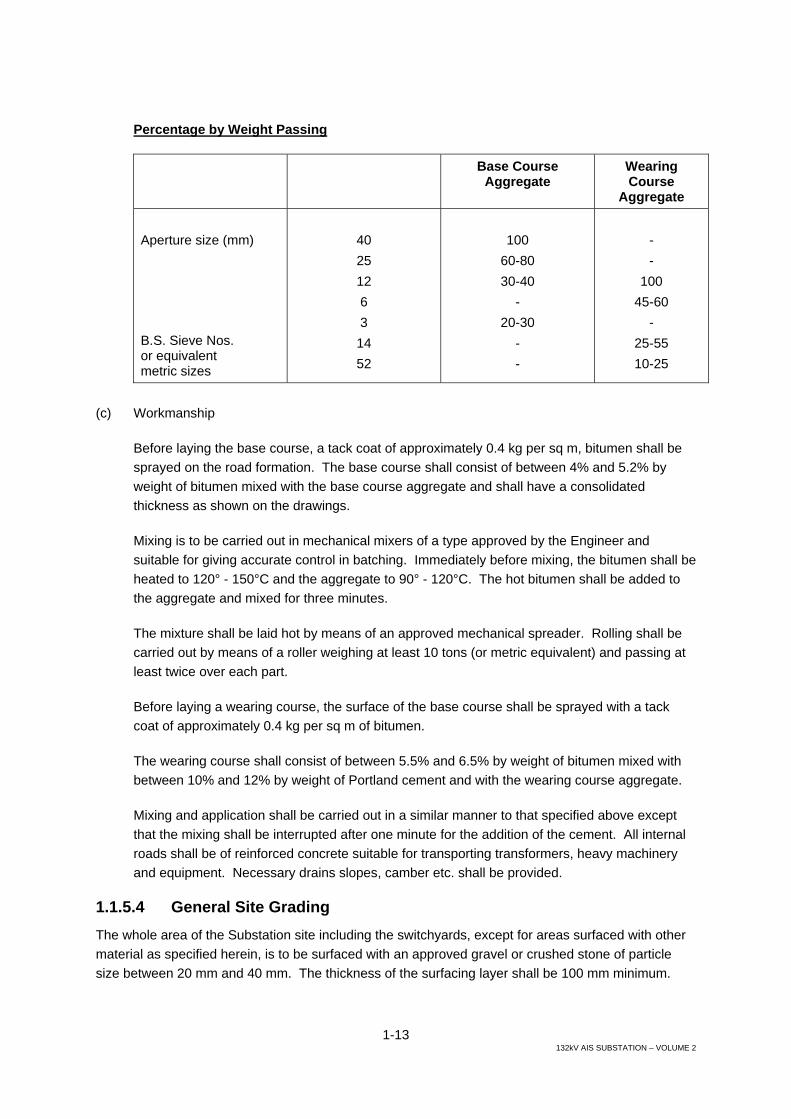
1-13 132kV AIS SUBSTATION – VOLUME 2
Percentage by Weight Passing
Base Course Aggregate
Wearing Course
Aggregate Aperture size (mm) B.S. Sieve Nos. or equivalent metric sizes
40 25 12 6 3 14 52
100
60-80 30-40
- 20-30
- -
- -
100 45-60
- 25-55 10-25
(c) Workmanship
Before laying the base course, a tack coat of approximately 0.4 kg per sq m, bitumen shall be sprayed on the road formation. The base course shall consist of between 4% and 5.2% by weight of bitumen mixed with the base course aggregate and shall have a consolidated thickness as shown on the drawings.
Mixing is to be carried out in mechanical mixers of a type approved by the Engineer and suitable for giving accurate control in batching. Immediately before mixing, the bitumen shall be heated to 120° - 150°C and the aggregate to 90° - 120°C. The hot bitumen shall be added to the aggregate and mixed for three minutes.
The mixture shall be laid hot by means of an approved mechanical spreader. Rolling shall be carried out by means of a roller weighing at least 10 tons (or metric equivalent) and passing at least twice over each part.
Before laying a wearing course, the surface of the base course shall be sprayed with a tack coat of approximately 0.4 kg per sq m of bitumen.
The wearing course shall consist of between 5.5% and 6.5% by weight of bitumen mixed with between 10% and 12% by weight of Portland cement and with the wearing course aggregate.
Mixing and application shall be carried out in a similar manner to that specified above except that the mixing shall be interrupted after one minute for the addition of the cement. All internal roads shall be of reinforced concrete suitable for transporting transformers, heavy machinery and equipment. Necessary drains slopes, camber etc. shall be provided.
1.1.5.4 General Site Grading The whole area of the Substation site including the switchyards, except for areas surfaced with other material as specified herein, is to be surfaced with an approved gravel or crushed stone of particle size between 20 mm and 40 mm. The thickness of the surfacing layer shall be 100 mm minimum.

1-14 132kV AIS SUBSTATION – VOLUME 2
1.1.5.5 Kerbs and Paving Slabs Kerbs shall be provided to roads as shown on the drawings. The kerbs shall be constructed of minimum C30 concrete to the sizes and forms as shown on the drawings. Expansion joints shall be formed with bitumen impregnated fibreboard approved by the Engineer and as shown on the drawings.
Paving slabs shall be cast in site from minimum C30 concrete. The slabs shall be 1000 mm by 1000 mm and to the thickness and details shown on the drawings.
Where fuel spillage may occur the Contractor shall design and install suitable concrete block paving.
Joints between adjacent slabs and blocks shall be filled with cement/sand mortar to the approval of the Engineer. The paving slabs shall be laid on a bed of Grade M grit sand to BS 882 l, as specified herein to a compacted depth of 35 to 50 mm.
1.1.5.6 Reinstatement The work shall include the reinstatement of all excavated and filled areas and areas damaged by the Contractor during the execution of this Contract. Each area shall be reinstated to match in line, grade, type, texture and appearance the material removed by the excavation work and the surfaces adjacent to the reinstated work.
1.1.6 Building and Associated Work The single 2-storey building containing 33 kV switchgear, 11/6.6kV switchgear, Control, relay and communications, and Cable Distribution Room shall be designed as reinforced concrete framed structures with reinforced concrete foundations, floors and roofs, and blockwork walls unless otherwise noted. Carports should be of similar construction.
The Guard House shall be designed as a reinforced concrete roof slab, supported on load bearing brickwork and reinforced concrete foundations shall be provided.
The structural framing for all buildings, suspended floors and roof slabs shall be designed in accordance with BS 8110 for reinforced concrete design. Where traffic loads are anticipated indoors the floor shall be designed to accommodate the required loadings.
The general arrangement and required criteria for all buildings is as shown on the drawings and it is the Contractor’s responsibility to ensure that all actual room sizes and arrangements are adequate for the satisfactory operation and maintenance of the type of equipment that is to be supplied. Adequate space shall be provided above, behind and in front of all switchgear and control panels and other equipment as shown on the enclosed tender drawings.
The Tenderer shall allow in his tender for any increase in size of the buildings over and above the typical shown on the drawings required by the equipment provided.
Cable trenches in buildings shall be constructed with falls to sumps, that are to be discharged into the surface water drainage system, and provided with pumps as necessary.

1-15 132kV AIS SUBSTATION – VOLUME 2
Perimeter infill and load bearing brick walls shall be carried down to reinforced concrete spread footings, to the same depth as the main building foundations and as the Engineer may direct. Details of these foundations shall be as indicated on the drawings and as specified herein.
Workshops, maintenance stores and the like shall be provided with suitable and approved over head travelling cranes or suitable fixed crane rails and lifting gear.
Each building of more than one storey shall be provided with a normal working stair case, as well as emergency escape stair case system.
All buildings shall be provided with suitable ladders to roof for inspection and maintenance.
Infill panels between the structural frame shall be constructed using insulated blockwork to achieve the required ‘U’ value. External walls shall be insulated to achieve a thermal transmittance value of 0.57 W/m2K or better. This ‘U’ value must also achieve the requirements of the Local Authority if greater.
All structural roofs shall be double pitched, or flat and be overlaid with a screed, to create falls towards the drainage outlet points as shown on the drawings. The buildings shall incorporate a parapet for architectural effect, and have direct rainwater run-off from the roof gutters at predetermined locations by downpipes discharging into the surface water system. A protected bituminous membrane inverted roof waterproofing system shall be provided in accordance with BS 8217: 2005, and shop drawings showing the build up of the complete waterproofing system and the detailing at all junctions, abutments and penetrations shall be submitted for approval prior to the commencement of the installation. The protective slabs over the roof insulation shall be of a weight to prevent them being dislodged by suction forces in high winds.
Live load deflections of beams shall be limited to 1/500 of the span.
Fire exit signage shall be provided on all escape routes and at all fire exit doors. The main construction and finishes required for the Substation buildings are set out below, these are not exhaustive and the Contractor shall provided suitable good quality finishes for areas not included • Building frame: Cast in-situ reinforced concrete columns, and beams
integrated with concrete roof and floor slabs. • Roof and floor slabs: Cast in situ reinforced concrete slabs integral with the
beams, with roof slabs overlaid with a screed laid to 1 to 80 minimum fall with minimum thickness of 50mm, and insulated to give the specified “U” values.
• Reinforcement: Deformed high yield bar to be used.
• Walls (external): Blockwork incorporating insulation to give the specified “U” values.
• Walls (internal): Non-load bearing blockwork with soft joint between the top of blockwork and the underside of the concrete slabs and beams.
1-16 132kV AIS SUBSTATION – VOLUME 2
Where the internal walls have a fire rating, the soft head joint should incorporate a fire seal of the same fire rating as the rest of the wall.
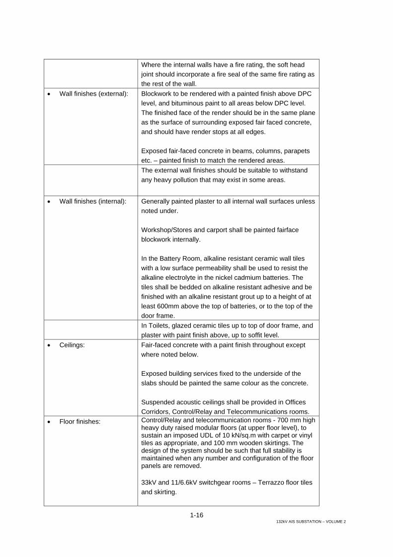
• Wall finishes (external): Blockwork to be rendered with a painted finish above DPC level, and bituminous paint to all areas below DPC level. The finished face of the render should be in the same plane as the surface of surrounding exposed fair faced concrete, and should have render stops at all edges. Exposed fair-faced concrete in beams, columns, parapets etc. – painted finish to match the rendered areas.
The external wall finishes should be suitable to withstand any heavy pollution that may exist in some areas.
• Wall finishes (internal): Generally painted plaster to all internal wall surfaces unless noted under. Workshop/Stores and carport shall be painted fairface blockwork internally. In the Battery Room, alkaline resistant ceramic wall tiles with a low surface permeability shall be used to resist the alkaline electrolyte in the nickel cadmium batteries. The tiles shall be bedded on alkaline resistant adhesive and be finished with an alkaline resistant grout up to a height of at least 600mm above the top of batteries, or to the top of the door frame.
In Toilets, glazed ceramic tiles up to top of door frame, and plaster with paint finish above, up to soffit level.
• Ceilings: Fair-faced concrete with a paint finish throughout except where noted below. Exposed building services fixed to the underside of the slabs should be painted the same colour as the concrete. Suspended acoustic ceilings shall be provided in Offices Corridors, Control/Relay and Telecommunications rooms.
• Floor finishes: Control/Relay and telecommunication rooms - 700 mm high heavy duty raised modular floors (at upper floor level), to sustain an imposed UDL of 10 kN/sq.m with carpet or vinyl tiles as appropriate, and 100 mm wooden skirtings. The design of the system should be such that full stability is maintained when any number and configuration of the floor panels are removed. 33kV and 11/6.6kV switchgear rooms – Terrazzo floor tiles and skirting.
1-17 132kV AIS SUBSTATION – VOLUME 2
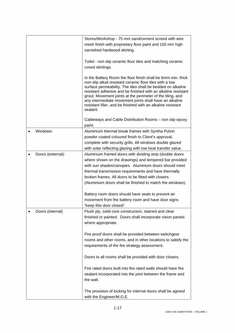
Stores/Workshop - 75 mm sand/cement screed with wire mesh finish with proprietary floor paint and 150 mm high varnished hardwood skirting. Toilet - non slip ceramic floor tiles and matching ceramic coved skirtings. In the Battery Room the floor finish shall be 6mm min. thick non-slip alkali resistant ceramic floor tiles with a low surface permeability. The tiles shall be bedded on alkaline resistant adhesive and be finished with an alkaline resistant grout. Movement joints at the perimeter of the tiling, and any intermediate movement joints shall have an alkaline resistant filler, and be finished with an alkaline resistant sealant. Cableways and Cable Distribution Rooms – non slip epoxy paint.
• Windows: Aluminium thermal break frames with Syntha Pulvin powder coated coloured finish to Client’s approval, complete with security grills. All windows double glazed with solar reflecting glazing with low heat transfer value.
• Doors (external): Aluminium framed doors with dividing strip (double doors where shown on the drawings) and tempered bar provided with sun shades/canopies. Aluminium doors should meet thermal transmission requirements and have thermally broken frames. All doors to be fitted with closers. (Aluminium doors shall be finished to match the windows). Battery room doors should have seals to prevent air movement from the battery room and have door signs “keep this door closed”.
• Doors (internal) Flush ply, solid core construction, stained and clear finished or painted. Doors shall incorporate vision panels where appropriate. Fire proof doors shall be provided between switchgear rooms and other rooms, and in other locations to satisfy the requirements of the fire strategy assessment. Doors to all rooms shall be provided with door closers. Fire rated doors built into fire rated walls should have fire sealant incorporated into the joint between the frame and the wall. The provision of locking for internal doors shall be agreed with the Engineer/M.O.E.

1-18 132kV AIS SUBSTATION – VOLUME 2
Electrolyte resistant paint to be provided on internal surface of Battery Room door.
• Roof waterproofing: Shall consist of bitumen impregnated polyester waterproof membrane laid on screed to fall, geotextile filter membrane, insulation and protective precast concrete tiles. The insulation shall achieve the specified ‘U’ value.
• Stairs: Stairs and landings shall be constructed in concrete, with stair flights a minimum of 1000mm wide. See further details in section Miscellaneous Metal of this specification.
1.1.7 Oil Containment for Transformer and Reactor Bunds, and Firewalls (a) Oil Containment
Power transformers and reactors shall be sited in oil containment areas and drain via a flame trap to an under ground facility to remove oil away from a fire in the event of an incident. The capacity of the underground containment shall be equal to the volume of oil contained within the transformer plus 50% to allow for fire fighting materials externally applied by the fire fighting service. Sumps shall be provided in the oil containment bunds, or underground containment tanks, such that rainwater can be manually pumped out a part of regular maintenance and after heavy or prolonged rainy periods. Where there is more than one power transformer on a site, it may be economic to link the oil containment drainage areas of these to a single underground tank with capacity for the largest transformer alone, thus reducing the excavation required. Connecting pipe work shall be designed to ensure rapid discharge of oil to the underground facility that, together with the pipe work, shall be resistant to transformer oil at a temperature of up to 80oC. Underground oil containment facilities shall be provided with a means of inspection and allow for pumping out of accumulated rain water or oil. The area within the transformer enclosure shall be designed as a water retaining structure to BS 8007 and coated with 2 coats of bituminous paint and be surfaced with a 100 mm thick layer of gravel on steel grating.
The road immediately adjacent to transformers used by oil handling equipment for maintenance shall be bunded/kerbed to contain any oil, and shall also drain to the containment facility to prevent ground pollution in the event of accidental spillage.
(b) Firewalls
Plant within close proximity of power transformers, and adjacent transformers, shall be protected by fire barrier walls or housed within a building with a fire resistant face towards the transformers. Protection should be provided for other circuits and transformers, control equipment, and external property.

1-19 132kV AIS SUBSTATION – VOLUME 2
Fire barrier walls and building fire resistant walls will be designed for 4 hour fire resistance and a blast pressure of 0.5 kN/ m2. Each fire barrier wall width shall be a minimum of 1000 mm wider at each side than the transformer, and the height shall be a minimum of 500 mm above the highest part of the transformer.
(c) Haulage Bollards
Haulage bollards shall be sited at positions in the switchyards, as will be indicated by the MOE Engineer, to assist in the handling of the heavy loads of transformers. The bollards shall be constructed in reinforced concrete, with reinforced concrete covers.
1.1.8 Concrete 1.1.8.1 Design, Materials and Workmanship Standards of design, materials and workmanship are to be equal to or better than those laid down in the latest amended editions of British Standard BS 8110. Alternative standards to BS 8110 should be international standards and require prior approval by the Engineer before application to the works.
1.1.8.2 Testing General Testing methods are to be in accordance with the relevant BS standard except as approved or requested by the Engineer.
Tests required by the Engineer will normally be carried out at an independent testing station. The cost preparing, storing and transporting test specimens to the place of testing is to be borne by the Contractor. Where there is no independent testing station within a reasonable distance of the Site the Engineer may allow the Contractor to set up his own full laboratories.
The Engineer shall have the right to order that any materials which do not meet with his approval shall not be used in the Works. The Contractor shall have the right to sample, test and give an opinion on such materials. If after this, the materials are rejected by the Engineer they shall be immediately removed from the Site by the Contractor.
The Contractor shall provide the Engineer with facilities for materials testing on Site. The facilities may be those normally used by the Contractor.
All testing facilities on site shall be calibrated at regular intervals in the presence of the Engineer’s representative and whenever deemed necessary by the Engineer.
1.1.8.3 Ready Mixed Concrete Ready mixed concrete as defined in BS 5328, batched off the Site, may be used only with the agreement of the Engineer and comply with all requirements of the Contract.
The concrete shall be carried by truck mixers. The concrete shall be compacted and in its final position within two hours of the introduction of cement to the aggregates, unless a longer time is agreed by the Engineer. The time of such introduction shall be recorded on the delivery note, together with the weight of the constituents of each mix.
1-20 132kV AIS SUBSTATION – VOLUME 2
When truck-mixed concrete is used, water shall be added under supervision, either at the Site or at the central batching plant, as agreed by the Engineer but in no circumstances shall water be added in transit.
Unless otherwise agreed by the Engineer, truck mixer units and their mixing and discharge performance shall comply with the manufacturers requirement. Mixing shall continue for the number and rate of revolutions recommended in manufacturer’s instructions. In the absence of instructions, mixing shall continue for not less than 100 revolutions at the rate of not less than seven revolutions per minute.
1.1.8.4 Cements - General The cements shall comply with all the requirements of British Standards latest edition.
Sulphate resisting cement shall be used for concrete below ground level.
All cement shall be obtained only from a source approved by the Engineer.
The Contractor shall not use cement varying from that used in the preparation of trial mixes until the permission of the Engineer has been obtained and until any further trial mixes required by the Engineer have been made and tested.
Additional protective measures such as bituminous painting should be applied on below grade concrete surfaces.
1.1.8.5 Cement Total Alkali Content The cement shall be tested to determine the total alkali content in accordance with BS 4550 Part 2:1970. Total alkali should not exceed 0.60%.
The equivalent weight of sodium oxide shall be calculated from the following formula: -
Equivalent weight of Na20=Wt. of Na20+0.658xWt. of K20. The equivalent weight of sodium oxide shall not exceed 0.6% of the weight of cement.
The above restriction shall be waived if the proposed aggregate is proved without doubt to be non-reactive.
1.1.8.6 Cement Delivery and Storage The cement shall be delivered to site packed in sealed bags or proper containers, of which there shall be 20 to the tonne, bearing the name of the brand and manufacturer and the number of the consignment. The approximate weight of the cement shall be legibly marked on each bag. The Contractor shall make the necessary arrangements for deliveries to be made sufficiently frequently to ensure freshness and in sufficient quantities to ensure that there is no suspension or interruption of the concreting work at any time.
The Contractor may use cement delivered in bulk; delivery arrangements shall be to the Engineer’s approval and each delivery must be accompanied by a manufacturer’s test certificate.

1-21 132kV AIS SUBSTATION – VOLUME 2
Each consignment of cement shall be brought to the site in sufficient time to allow any tests to be carried out before the cement is required to be used.
Cement in bags shall be unloaded under cover and stored in a well ventilated and weatherproof building used exclusively for this purpose. The floor of the building shall be at least 150 mm off the ground and an air space shall be left between the floor and bottom layer of bags.
If delivered in bulk an approved type of cement silo shall be used.
Each consignment shall be stored separately so as to permit easy access for inspection and a record shall be kept so that each consignment may be identified. Storage shall be arranged so that the cement is used in order of delivery.
Cement which is more than 12 weeks old from the date of delivery shall be retested on site for fineness, setting time strength and soundness in the presence of the Engineer’s representative and full test reports shall be submitted within 24 hours.
1.1.8.7 Cement Test Certificates and Samples All cement shall be certified by the manufacturer as complying with the requirements of the appropriate specification. The Contractor shall, when required by the Engineer, obtain for him the manufacturer’s test certificate for any consignment as soon as possible after delivery.
For every 50 tonnes of cement delivered to site and whenever required by the Engineer the Contractor shall take samples, under supervision, of the cement stored on, or delivered to the site. The Contractor shall test such samples as laid down in clause 9.6 above.
1.1.8.8 Aggregates General Before the Engineer can approve any aggregate source the Contractor shall furnish the following data: -
(i) Petrological group of rock (ii) Rock type within the group (iii) Shape (iv) Surface texture (v) Site content (vi) Grading curves (vii) Specific gravity (viii) Impact value (ix) Water absorption (x) Soundness (xii) Salt content (xiii) Alkali reactivity
The fine and coarse aggregates shall comply with BS 882 and Clauses 9.9 and 9.10 unless exceptions listed by Tenderer in the attached schedule are approved by the Engineer.
The sources of all aggregates shall be approved by the Engineer.

1-22 132kV AIS SUBSTATION – VOLUME 2
1.1.8.9 Aggregate Physical Requirements (i) The weight of voided shells in fine aggregate shall not exceed 5%.
(ii) The weight of the clay and fine silt fraction (smaller than ASTM sieve no. 200) shall not exceed 5% by weight for coarse aggregates or 10% by weight for fine aggregates.
(iii) Absorption of fine and coarse aggregate shall not exceed 5% as measured in accordance with BS 812 or similar standard.
(iv) The soundness of all aggregates shall be proved by a sodium sulphate test in accordance with ASTM C88-73, from which the loss over five cycles shall not exceed 10% for fine aggregates or 12% for coarse aggregates.
(v) The apparent specific gravity of aggregates as determined by an approved test, such as BS 812, shall not be less than 2.5.
(vi) Loss angles abrasion shall not exceed 37%.
(vii) Alkali reactivity of aggregates should be in accordance with ASTM/C-227 and C-289. Only those aggregates considered to be innocuous should be permitted.
Where quarries win aggregate from bedrock, especially limestone of the dolomitic type, the rock shall be checked for surface alternation to hardpan. This may affect the surface for well over a meter depth and result in salt concentrations near the surface. Such rocks are also prone to other undesirable characteristics, including pockets of clay, salt, chalk or other friable material. Rigorous initial physical inspection is essential.
1.1.8.10 Aggregate Chemical Requirements (i) Fine and coarse aggregates shall not be potentially reactive with alkalis and shall be regularly
tested in accordance with ASTM standard tests C228, C289, C342 and C586.
(ii) Fine and coarse aggregate shall not contain more than 0.5% by weight of acid soluble sulphates (as S03).
(iii) Fine aggregate shall contain no more than 0.1% by weight of chlorides (as NaC1) and coarse aggregate not more than 0.03% should these figures be exceeded the aggregate may still be considered acceptable in this respect provided the total sodium chloride concentration is not greater than 0.32% by weight of cement in the mix, irrespective of the origin of the chloride.
(iv) Marine aggregates may be used provided that the content of chloride salt in the aggregate, expressed as the equivalent anhydrous calcium chloride percentage by weight of the cement to be used in the concrete, does not exceed 0.3% but where the proportion exceeds 0.1% by weight of cement, marine aggregates must not be used with high alumina cement or for pre-stressed concrete in circumstances where calcium chloride admixtures are not permitted. In addition, in concrete containing embedded metal, calcium chloride shall not be added.

1-23 132kV AIS SUBSTATION – VOLUME 2
1.1.8.11 Aggregate Storage The aggregates shall be stored at mixer positions in such a manner that intermingling of different sizes and types of aggregates is prevented. The stock-piles are to be protected from rubbish or windblown dust.
Heaps of fine aggregate shall be capable of draining freely. Wet fine aggregate shall not be used until, in the opinion of the Engineer, it has drained sufficiently to ensure proper control of the water/cement ratio.
1.1.8.12 Aggregate Sampling and Testing The Engineer shall have the right to require the Contractor at any time, to draw samples of aggregate from stockpiles on the Site or any other location to be indicated by the Engineer. All sampling and testing shall be in accordance with BS 812, BS EN 1097, or to American standards when no appropriate BS exists.
For each new source of aggregate and for each class of aggregate to be used sampling and testing shall be done at the rate of six samples and set of tests for each new source and each new class.
The Contractor shall allow for the whole range of tests to be carried out. For routine sampling and testing from an approved source the rate shall be one sample per 50 m of aggregate to be used or one sample per month whichever is greater. Such testing shall include those tests from BS 812 as are considered useful by the Engineer for comparison with the results of the initial set of tests but the Contractor shall allow for the full range to be carried out.
Testing is to be carried out at an independent laboratory approved by the Engineer or else on the site in the presence of the Engineer’s representative, where approved by the Engineer.
1.1.8.13 Water for Concrete The water used for making concrete, mortar and grout shall be clean, fresh and free from injurious amounts of oil, vegetable or organic matter or any other deleterious substance in suspension or solution. The mix water shall be continually monitored for salt content and the concrete mix designed accordingly to limit total salt content.
The water should comply with the requirements of BS 3148.
1.1.8.14 Admixtures Admixtures shall not be used without the approval of the Engineer.
Before the use of any admixture can be approved the Contractor must prove by trial mix procedures that the concrete will in no way be adversely affected even when twice the recommended dose is batched.
1-24 132kV AIS SUBSTATION – VOLUME 2
1.1.8.15 Plant The concreting plant shall be suitable in type, capacity and design for its purpose. The performance of the plant and its disposition shall be to the satisfaction of the Engineer. The plant shall be maintained regularly and standby plant shall be available to avoid any delay in the progress of the works.
1.1.8.16 Concrete Strength Requirements All concrete mixes shall be in accordance with the requirements of BS 5328 or similar approved and as designated on drawings approved by the Engineer.
(a) Reinforced compressive cube strength shall not be less than 30 N/mm² after 28 days, designated C30.
(b) Compressive cube strength of the plain concrete shall not be less than 15 N/mm² after 28 days. Plain concrete shall be laid under reinforced concrete foundations, ground beams, trenches etc., with thickness not less than 100 mm, designated C15.
(c) Compressive strength of the plain concrete which is used for unreinforced parts of the structures shall not be less than 20 N/mm² after 28 days, designated C20.
At least seven weeks before concrete construction is programmed to start the Contractor shall submit for approval all the details listed in the table in this section, below, for each proposed grade of concrete. No concrete drawings will be approved until this data is received.
Sampling rates shall comply generally with the table in the section on Works Test Cubes, below.
The strength requirements for each grade of concrete proposed in the design shall be proven by means of preliminary trial tests as specified later. The minimum cement content shall be 240 kg/cu.m for 40 mm nominal size aggregate and 280 k/cu.m for 20 mm aggregate. The maximum free water-cement ratio shall be 0.55. These figures shall be revised if the sulphate content of the soil is greater than 0.5% (total S03).
The Contractor’s designs and drawings shall show clearly the characteristic strengths, mix proportion and permissible deviation proposed for each grade of concrete to be used.
The Contractor shall carry out frequent tests to the satisfaction of the Engineer to check the relationship of the strength of concrete cured under site conditions to that cured under laboratory conditions.

1-25 132kV AIS SUBSTATION – VOLUME 2
Specified requirements of several different mixes to be used on one Contract (Refer to BS 5328).
CONTRACT Mix description used on Drawings
Type of mix
Type of cement BS No.
Coarse: BS No
Type of aggregate
Fine: BS No.
Nominal size Aggregate Maximum (mm)
Grade
Minimum Cement Content (kg/m3)
Sampling Rate (mm3)
Slump (mm)
VB(s)
Workability
Compacting Factor
Maximum free water/cement ratio
Maximum Cement Content (kg/m3)
Special Cement
Coarse: Special Aggregate
Fine:
Fine Aggregate (%)
Specified
Prohibited
Admixture
Amount
Air Content
Maximum Temperature of fresh concrete (ºC)
Minimum

1-26 132kV AIS SUBSTATION – VOLUME 2
CONTRACT Mix description used on Drawings
Maximum Density of Concrete (kg/m3)
Minimum
Additional requirements on attached schedule
1.1.8.17 Concrete Mixing All concrete except where specially permitted by the Engineer in writing shall be mixed in weight batch mixing machines. The machine shall have a large water storage tank with a gauge so that a predetermined quantity of water can be injected direct into the mixer drum.
The dry concrete ingredients shall be mixed until a uniform colour is obtained. After the addition of the water the concrete shall be mixed for a further two minutes or until a uniform colour is achieved. The total water in the mix shall not exceed the amount used in the trial mix.
In computing the quantity of water to be added, due account must be taken of the water contained in the aggregates. The amount of water shall be sufficient to ensure through hydration, good workability and high strength.
The Contractor shall take all precautions to the satisfaction of the Engineer to protect the concrete from the injurious effects of the elements.
1.1.8.18 Workability The concrete shall be of such consistency that it can be readily worked into the corners and angles of the formwork and around reinforcement without segregation of the materials or bleeding of free water at the surface. On striking the formwork it shall present a face which is uniform, free from honey combing, surface crazing or excessive dusting and which shall not, in the opinion of the Engineer, be inferior to the standards laid down in later clauses in this section.
In order to satisfy the Engineer that the workability of the proposed mix in the various grades is adequate for the requirements of the Specification, the Contractor shall carry out a series of workability tests on the preliminary trial mixes required elsewhere in this section. These tests shall be carried out in accordance with BS 1881, or such other procedure as may be approved by the Engineer.
When a specific workability is called for a check shall be maintained by measuring slump at the rate of one test for each ten cubic metres of concrete or three tests for each day of concreting.
1.1.8.19 Transportation The concrete shall be discharged from the mixed and transported to the Works by means that shall be approved by the Engineer and which shall prevent adulteration, segregation or loss of ingredients and ensure that the concrete is of the required workability at the point and time of placing.

1-27 132kV AIS SUBSTATION – VOLUME 2
1.1.8.20 Placing The concrete shall be placed in the positions and sequences indicated on approved drawings, in the specification or as directed by the Engineer, within one hour of mixing.
All formwork and reinforcement contained in it shall be clean and free from standing water, snow or ice immediately before the placing of the concrete.
The Engineer shall be given 24 hours notice of concrete placement in order that he may check the work.
Except where otherwise directed, concrete shall not be placed unless the Engineer or his representative is present and has previously examined and approved the positioning, fixing and condition of the reinforcement and of any other items to be embedded, the cleanliness, alignment and suitability of the containing surfaces and the adequacy and position of the plant.
The concrete shall be deposited as nearly as possible in its final position and in such a manner as to avoid segregation, displacement of the reinforcement, formwork or other embedded items. Placing shall be continuous between specified or approved construction joints. Works shall be brought up to full thickness in 500 mm maximum compacted layers as the work proceeds.
Where chutes are used to convey the concrete, their slopes shall not be such as to cause segregation and suitable spouts or baffles shall be provided to obviate segregation during discharge. Concretes shall not be allowed to fall freely more than 1.5 metres except with the approval of the Engineer. Where pneumatic placers are used the velocity of discharge shall be regulated by suitable baffles or hoppers where necessary to prevent segregation or damage and distortion of the reinforcement, other embedded items and formwork, caused by impact.
Upon arrival at the places of deposition the concrete truck driver must present to the Engineer’s representative a chit from the concrete batcher stating (a) the grade of concrete (b) the workability (c) the aggregate size (d) type of cement and (e) time of batching of the concrete. Records shall be maintained detailing the placement location of each batch within the works.
If concreting is not started within 24 hours of approval being given, approval shall again be obtained from the Engineer. Concreting shall then proceed continuously over the area between construction joints. Fresh concrete shall not be placed against in situ concrete which has been in position for more than 30 minutes unless a construction joint is formed in accordance with this specification. When in situ concrete has been in place for four hours, or less as directed by the Engineer depending upon the mix, type of cement and weather conditions, no further concrete shall be placed against it for a further 20 hours.
Concrete, when deposited, shall have a temperature of not less than 5ºC and not more than 32ºC. It shall be compacted in its final position within 30 minutes of discharge from the mixer unless carried in purpose made agitators, operating continuously, when the time shall be within two hours of the introduction of cement to the mix and within 30 minutes of discharge from the agitator.

1-28 132kV AIS SUBSTATION – VOLUME 2
Except where otherwise agreed by the Engineer, concrete shall be deposited in horizontal layers to a compacted depth note exceeding 500 mm where internal vibrators are used or 300 mm in all other cases.
Unless otherwise agreed by the Engineer, concrete shall not be dropped into place from a height exceeding 1.50 metres. When trunking or chutes are used they shall be kept clean and used in such a way as to avoid segregation.
No concrete shall be placed in flowing water. Underwater concrete shall be placed in position by tremie tube, or by pipeline from the mixer. Full details of the method proposed shall be submitted in advance to the Engineer and his approval obtained before placing begins. Where the concrete is placed by a tremie tube, its size and method of operation shall be in accordance with BS 8004. During and after concreting under water, pumping or de-watering operations in the immediate vicinity shall be suspended until the Engineer permits them to be continued.
1.1.8.21 Compaction of Concrete The concrete shall be fully compacted throughout the full extent of the layer. It shall be thoroughly worked against the formwork and around reinforcement and other embedded items, without displacing them. Successive layers of the same lift shall be thoroughly worked together.
All concrete shall be compacted to produce a dense homogenous mass. Unless otherwise agreed by the Engineer, it shall be compacted with the assistance of vibrators. Sufficient vibrators in serviceable condition shall be on site so that spare equipment is always available in the event of breakdowns.
Vibration shall not be applied by way of the reinforcement. Where vibrators of the immersion type are used, contact with reinforcement and all inserts shall be avoided, so far as is practicable.
Concrete shall not be subjected to vibration between 2 and 24 hours after compaction.
1.1.8.22 Vibrators Unless otherwise directed by the Engineer, approved power driven vibrators of the immersion type shall be used.
They shall be inserted at such distances apart or applied in such a manner as will ensure that the concrete is satisfactorily and uniformly compacted.
The Contractor shall ensure that a sufficient number of vibrators are on hand at all times including allowance for breakdown of vibrators.
As a general rule, one working vibrator shall be available for each 6m3/hr of concrete being placed.
Vibrators shall penetrate the full depth of the layer and where concrete is placed over previously placed concrete not more than four hours old the vibrators shall enter and re-vibrate that layer to ensure that successive layers are well knitted together.

1-29 132kV AIS SUBSTATION – VOLUME 2
Over-vibration, causing segregation, surface laitance or leakage through formwork, shall be avoided. Immersion vibrators shall be withdrawn slowly to prevent the formation of voids. Vibrators shall not be used to work the concrete along the forms, or in such a way as to damage formwork or other parts of the structure, or displace the reinforcement of other embedded items.
Internal vibrators shall be capable of producing not less than 10,000 cycles per minute and external vibrators not less than 3,000 cycles per minute.
1.1.8.23 Construction Joints Concreting shall be carried out continuously up to construction joints, the position and arrangement of which shall be indicated on the drawings and approved by the Engineer.
When not indicated on the drawings the following general rule shall apply: -
Columns Joints in columns are to be made at the underside of floor members and at floor levels. Haunches and column capitals are to be considers as part of and continues with the floor or roof.
Floors Joints in the floor system are to be located at or near the quarter points of the span in slabs and beams, except where otherwise instructed.
Walls Vertical joints away from corners. Horizontal joints above splays or openings.
Whenever the placing of the concrete is discontinued other than at the exposed faces, this dis-continuity shall form a construction joint. Construction joints are to be made only along a horizontal or vertical plan except that in the case of inclined or curved members they shall be at right angles to the principal axis. Care shall be taken to prevent off setting of the joint and to ensure water tightness. The joints shall in every way satisfy the requirement of the Engineer, and be fully detailed on drawings prior to submission for approval.
When work is resumed adjacent to a surface which has set, the whole surface shall be thoroughly roughened. It shall be cleaned of all loose and foreign matter and laitance and washed with water immediately before placing the fresh concrete which shall be well compacted against the joint.
1.1.8.24 Construction Bays The Contractor shall agree with the Engineer, prior to the commencement of concreting, upon the sequence of placing concrete and positions of vertical and horizontal joints, whether shown or not on the drawings.
In general, slabs in excess of 6 metres in length and/or width and walls exceeding 6 metres in length shall not be poured in one operation and subsequent adjacent bays shall not be concreted within seven days. The maximum area of any pour shall be 100 sq.m.
1-30 132kV AIS SUBSTATION – VOLUME 2
In the light of experience the Engineer may consider the above pour size limits to be excessive and will have the authority to reduce them.
As an alternative to alternate bay construction, shrinkage gaps of up to 1 metre in the width may be left a 6 metre intervals; the shrinkage gaps shall not be concreted until concrete on all sides is at least seven days old.
Expansion joints shall be fully detailed on construction drawings before submission for approval. Minimum width of expansion joints to be 25 mm except for shaded areas 12 mm.
Expansion joints shall be filled with bitumen impregnated fibreboard to full depth and width. The infilling will be permitted to be used as permanent formwork only for the second casting. where the fibreboard is exposed it shall be cut back for a depth of at least 2 cm from the chamfered edge, filled and pointed with a resilient liquid polysulphide polymer sealant to the manufacturer’s instructions.
Where dowel bars are indicated on the drawings forming part of a joint they shall be held securely horizontal and perpendicular to the joint during concreting.
Dowel bars shall be plain mild steel bars conforming with BS 4449; they shall be straight and coated at one end with approved bond breaking compound, which shall consist essentially of 66% of 200 pen bitumen blended not with 14% light creosote oil and, when cold, brought to the consistence of paint by the addition of 20% solvent naptha, or other approved compound.
Plastic caps used in expansion joints shall be rigid and securely fixed to the dowel to prevent the ingress of concrete during casting of the slab. The packing used within the cap shall be an insert compressible material. All dimensions must be shown on drawings prior to submission for approval.
1.1.8.25 Joining New Concrete Work to Existing Existing concrete shall be broken out as described or directed and scabbled to form a suitable key for the concrete.
Where necessary the reinforcement in existing concrete shall be exposed, cleaned and bent to its correct shape.
New reinforcement shall be securely wired to the existing.
1.1.8.26 Curing Concrete shall be protected during the first stage of hardening from the harmful effects of sunshine, drying winds, cold, rain or running water. The protection shall be applied as soon as practicable after completion of placing by a method to be approved by the Engineer.
The Contractor shall put forward his proposals for curing concrete to the Engineer for approval, before any concreting work commences.
On vertical surfaces, the curing membrane shall be applied immediately after removing the formwork.
1-31 132kV AIS SUBSTATION – VOLUME 2
No concrete shall be allowed to become alternately wet and dry.
The temperature of curing water shall be the same as the concrete +10ºC. General concrete shall be wet cured for at least seven days with further four days of dry protection.
1.1.8.27 Trial Mixes The Contractor shall submit not less than three weeks before the commencement of manufacture of preliminary trial design mixes the following information to the Engineer in respect of each grade of concrete.
(a) Grade of concrete.
(b) Title of particular trial mix.
(c) The grading of the aggregates.
(d) The ratio by weight of all the constituents of the concrete.
(e) The expected compacting factor and slump.
(f) Full details of the proposed site quality control.
(g) Full details of the proposed laboratory for testing.
The Contractor shall also confirm his proposed testing regime and acceptance criteria for the Preliminary Trial Mixes which should be based on BS 5328. Should the proposal not be approved by the Engineer, then the Contractor shall comply with the paragraph on preliminary test cubes and the two following paragraphs below.
At least four weeks before commencing any concreting in the Works, the Contractor shall make trial mixes using samples of aggregates and cements typical of those to be used. If possible, the concreting plant and the means of transport to be employed in the Works shall be used to make the trial mixes and to transport them a representative distance. A clean dry mixer shall be used to make the trial mixes and the first batch shall be discarded.
Before commencing the Works the Contractor shall submit to the Engineers for his approval, full details of the mixes he proposes to use, with their anticipated strength, which must be based on the satisfactory results of these preliminary tests.
The Engineer shall if he so desires be present at all preliminary tests. The Contractor shall inform the Engineer of his intention to carry out such tests and the time and place of the tests a least 24 hours before they take place.
Neither the mix proportions nor the source of supply of materials shall be altered without the prior approval of the Engineer except that the Contractor shall adjust the proportions of the mix as required, to take account of permitted variations in the materials. Such approval shall be subject to the execution, to the Engineer’s satisfaction, of trial mix procedures set out herein.
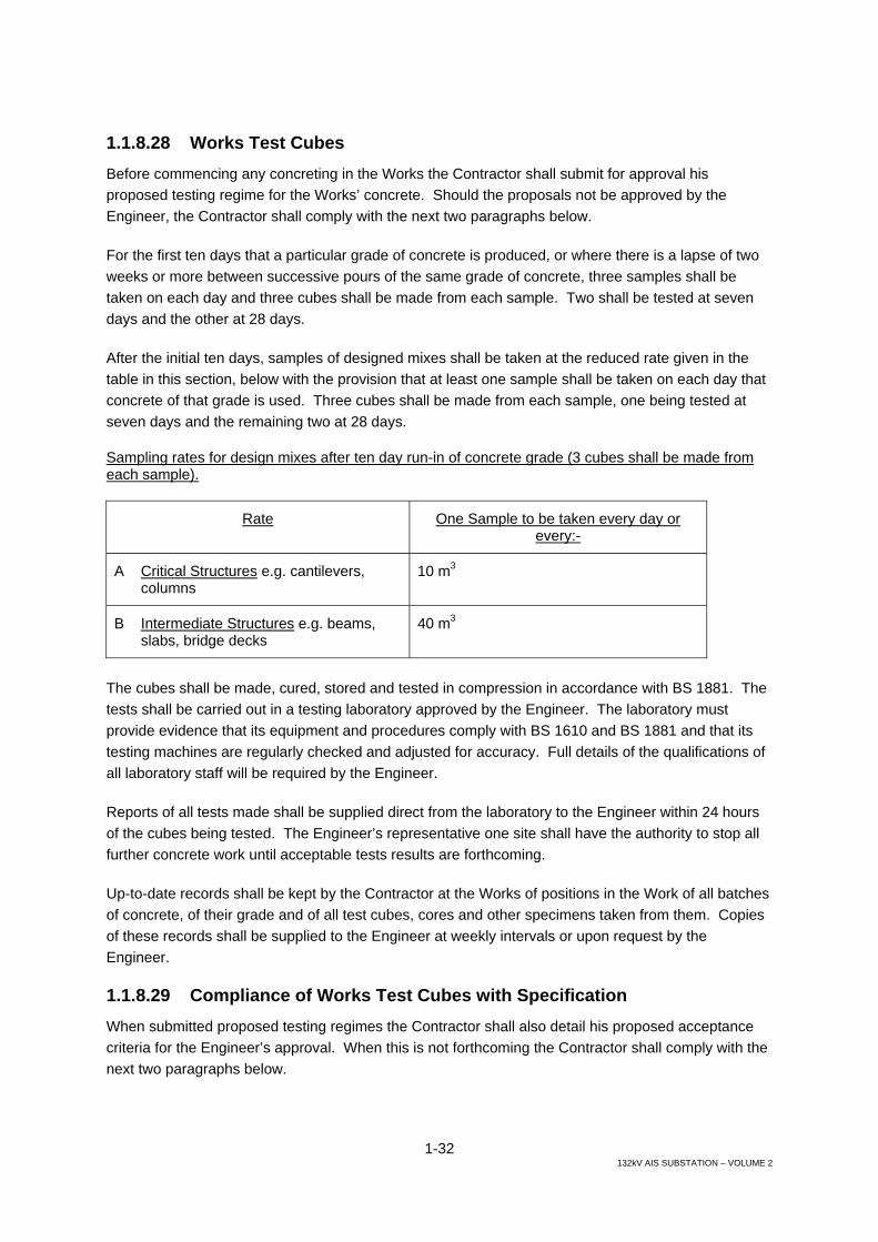
1-32 132kV AIS SUBSTATION – VOLUME 2
1.1.8.28 Works Test Cubes Before commencing any concreting in the Works the Contractor shall submit for approval his proposed testing regime for the Works’ concrete. Should the proposals not be approved by the Engineer, the Contractor shall comply with the next two paragraphs below.
For the first ten days that a particular grade of concrete is produced, or where there is a lapse of two weeks or more between successive pours of the same grade of concrete, three samples shall be taken on each day and three cubes shall be made from each sample. Two shall be tested at seven days and the other at 28 days.
After the initial ten days, samples of designed mixes shall be taken at the reduced rate given in the table in this section, below with the provision that at least one sample shall be taken on each day that concrete of that grade is used. Three cubes shall be made from each sample, one being tested at seven days and the remaining two at 28 days.
Sampling rates for design mixes after ten day run-in of concrete grade (3 cubes shall be made from each sample).
Rate One Sample to be taken every day or every:-
A Critical Structures e.g. cantilevers, columns
10 m3
B Intermediate Structures e.g. beams, slabs, bridge decks
40 m3
The cubes shall be made, cured, stored and tested in compression in accordance with BS 1881. The tests shall be carried out in a testing laboratory approved by the Engineer. The laboratory must provide evidence that its equipment and procedures comply with BS 1610 and BS 1881 and that its testing machines are regularly checked and adjusted for accuracy. Full details of the qualifications of all laboratory staff will be required by the Engineer.
Reports of all tests made shall be supplied direct from the laboratory to the Engineer within 24 hours of the cubes being tested. The Engineer’s representative one site shall have the authority to stop all further concrete work until acceptable tests results are forthcoming.
Up-to-date records shall be kept by the Contractor at the Works of positions in the Work of all batches of concrete, of their grade and of all test cubes, cores and other specimens taken from them. Copies of these records shall be supplied to the Engineer at weekly intervals or upon request by the Engineer.
1.1.8.29 Compliance of Works Test Cubes with Specification When submitted proposed testing regimes the Contractor shall also detail his proposed acceptance criteria for the Engineer’s approval. When this is not forthcoming the Contractor shall comply with the next two paragraphs below.
1-33 132kV AIS SUBSTATION – VOLUME 2
The rules of compliance for works cubes are different to those in Clause 9.27 for Trial Mixes. Compliance with the characteristic strength shall be assumed if the conditions given in both (a) and (b) are met: -
(a) The average strength from any group of four consecutive test results exceeds the specified characteristic strength by
3N/mm2 for concrete of grade C-25 and above (i.e. characteristic strength = 25N/mm²).
2N/mm² for concrete of grade C-15 and below (i.e. characteristic strength = 15N/mm²).
(b) The strength determined from any test result is not less than the specified characteristic strength minus.
3N/mm² for concrete of grade C-25 and above
2N/mm² for concrete of grade C-15 and below
The quantity of concrete represented by any group of four consecutive test results shall include the batches from which the first and last samples were taken, together with all intervening batches. When a test result fails to comply with (b), only the particular batch from which the sample was taken shall be at risk.
Compliance criteria remain the same irrespective of every rate of sampling or the same grade concrete in different structures.
Where a minimum or maximum cement content of a designed mix is specified and compliance is assessed by observation of the batching or from autographic records, the cement content shall not be less than 95% of the specified minimum or more than 105% of the specified maximum.
Where compliance of cement content is assessed from the results of analysis tests on fresh concrete, the cement content shall not be less than 90% of the specified minimum or more than 110% of the specified maximum.
1.1.8.30 Failure of Concrete to Meet Test Requirements If the strength of the specimen is less than the appropriate specified minimum crushing strength or if, in the opinion of the Engineer, the concrete fails to meet the specified requirements in other respects, the concrete in that part of the Works of which it is a sample will be considered not to comply with the specified requirements.
As and where directed by the Engineer, cylindrical core specimens shall be cut from the hardened concrete in the Works for the purposes of examination and testing. The cutting equipment and the method of doing the work shall be approved by the Engineer. Prior to the preparation for testing, the specimens shall be made available for examination by the Engineer. Testing of the core shall be in accordance with approved standards.
1-34 132kV AIS SUBSTATION – VOLUME 2
Recourse may also be made by the Engineer to such non-destructive means of testing as ultrasonic pulsing and Schmidt rebound hammers.
If the specified requirements have not been met, the Contractor shall propose such remedial action as may be required. Such action is subject to the Engineer’s satisfaction and approval. If no satisfactory remedial measures are proposed by the Contractor and approved by the Engineer then the Engineer shall order the removal of all work not complying with the Specification at the Contractor’s expense. Before proceeding with similar work the Contractor shall submit to the Engineer, for his approval, details of action proposed to ensure future concrete to be placed in the Works will comply with the Specification.
1.1.8.31 Formwork Forms shall be so designed and constructed that the concrete can be properly placed and thoroughly compacted and that the hardened concrete while still supported by the forms shall conform accurately to the required shape, position and level, subject to the tolerances specified and to the standards of finish specified later in this Section.
The Engineer may request the Contractor to provide sample panels of formwork for approval, at the Contractor's expense.
When concrete is to be vibrated, special care shall be taken to maintain the stability of the formwork and the tightness of the joints during vibrating operations.
The material and position of any ties passing through the concrete shall be approved by the Engineer. The whole or part of the tie shall be capable of being removed so that no part remaining embedded in the concrete shall be nearer the surface of the concrete than the specified thickness of cover to the reinforcement. Any holes left after the removal of ties shall be filled, unless otherwise directed by the Engineer, with concrete or mortar of approved composition.
1.1.8.32 Removal of Formwork All forms shall be removed without damage to the concrete. The use of mould oil or other material to facilitate this shall be subject to the approval of the Engineer.
All formwork for pits, ducts and holding down boltholes must be so constructed that it can be easily collapsed to facilitate withdrawal after the initial set of the concrete.
The Contractor's proposed method for the construction and fixing of the formwork for boltholes pockets shall be submitted to the Engineer for approval before construction. The top of the shuttering shall be suitably covered to prevent entry of excess grout, materials used for curing, etc.
Solid timber must not be used for forming holding down boltholes. Boltholes formers may be made of plywood, expanded metal, polystyrene or other method approved by the Engineer, who may require the Contractor to carry out a test pour, using the proposed bolthole former.
The Engineer shall be informed in advance when the Contractor intends to strike any formwork.

1-35 132kV AIS SUBSTATION – VOLUME 2
The time at which the formwork is struck shall be the Contractor's responsibility. The formwork may be struck when the concrete has, in the opinion of the Engineer, attained a compressive strength of not less than 10N/mm2 or twice the stress to which it will then be subjected, whichever is the greater.
In the absence of cube test results the periods before striking given in the table below may be used for ordinary Portland cement: -
Location Surface temperature of concrete Not less than
16 C Not less than 7 C
Beam side, walls and columns Slab soffits (formwork)
12 hrs 4 days
18 hrs 7 days
Formwork props to slabs 11 days 15 days Beam soffits (formwork props undisturbed) 10 days 15 days Formwork props to beams 15 days 21 days
Formwork shall be constructed so that the side forms of members can be removed without disturbing the soffit forms and its props are to be left in place, when the soffit forms are removed these props shall not be disturbed during the striking.
1.1.8.33 Finishes of Concrete The Contractor shall state precisely on his plans which of the types of finishes d described hereunder he intends to use in the various locations. Any defective concrete finish will be rejected. The Engineer may at his discretion order the defects to be cut out and made good.
Plastering of defective concrete as a means of making good will not be permitted, except that in case of minor porosity on the surface the Engineer may approve a surface treatment by rubbing down with cement and sand mortar of the same richness as in the concrete. This treatment shall be made immediately after removing the formwork.
1.1.8.34 Formed Finishes for Concrete (a) Type F.1
This finish is for surfaces against which backfill or further concrete will be placed. Formwork shall consist of sawn boards, sheet metal or any other suitable material, which will prevent the loss of grout when the concrete is vibrated.
(b) Type F.2
This finish is for surfaces, which are permanently exposed to view but where the highest standard of finish is not required. Forms to provide a Type F.2 finish shall be smooth and boards shall be not less than 18mm thick with edges, arranged in a uniform pattern. Alternatively, metal panels may be used if they are free from defects likely to detract from the general appearance of the finished surface. Joints between the boards and panels shall be
1-36 132kV AIS SUBSTATION – VOLUME 2
horizontal and vertical unless otherwise directed. This finish shall be such as to require no general filling of surface pitting, but fines, surface discoloration and other minor defects shall be remedied by methods approved by the Engineer.
(c) Type F.3
This finish is for surfaces prominently exposed to view where good appearance and alignment are of special importance. To achieve this finish, which shall be free of board marks, the formwork shall be faced with plywood or equivalent material in large sheets. The sheets shall be arranged in an approved uniform pattern whenever possible.
Joints between sheets shall be arranged with architectural feature, sills, window heads or drainages in direction of the surface. All joints between panels shall be vertical and horizontal unless otherwise directed. Suitable joints shall be provided between sheets to maintain accurate alignment in the place of the sheets. The joints shall be arranged and fitted so that no blemish or mark is imported to the finished surface. Unfaced wrought boarding or standard steel panels will not be permitted for Type F.3 finish. Permanent forms shall be constructed of slabs or blocks of precast concrete, natural stone, brickwork of other approved material as directed. Such slabs or blocks shall have an exposed surface of the quality shown on the drawings and as specified. They shall be fixed to the structure by approved means and the joints between them shall be made tight with mortar or other means of preventing leakage. The use of internal metal ties shall not be allowed.
(d) Type F.4
This finish is identical to type F.3 except that internal metal ties are permitted.
1.1.8.35 Unformed Finishes to Concrete (a) Type U.1
This is a screeded finish for surfaces of roads or of foundations, beds, slabs and structured members to be covered by backfills, subsequent stages of construction, bonded concrete, topping or cement mortar beds to receive pavings and on exposed surfaces or paving where superior finish is not required. It is also the first stage for finishes Type U.2 and U.3. The finishing operations shall consist of levelling and screeding the concrete to produce a uniform plane or ridged surface, surplus concrete being struck off by straight edge immediately after compaction.
(b) Type U.2
This is a floated finish for surfaces of beds and slabs to receive mastic pavings or block or tile pavings where a hard smooth steel trowelled surface is not required. Floating shall be done only after the concrete hardens sufficiently and may be done by hand or machine. Care shall be taken that the concrete is worked no more than is necessary to produce a uniform surface free from screed marks.
1-37 132kV AIS SUBSTATION – VOLUME 2
(c) Type U.3
This is a hard smooth steel-trowelled finish for surfaces of concrete pavings, tops of walls, exposed surfaces of engine and plant foundations and in the vicinity of holding down bolt chases, copings and other members exposed to weathering, surface beds and slabs to receive thin flexible sheet and tile pavings bedded in adhesive and seatings for bearing plates and the like, where the metal is in direct contact with the concrete.
Trowelling shall not commence until the moisture film has disappeared and the concrete has hardened sufficiently to prevent excess laitance from being worked to the surface. The surface shall be trowelled under firm pressure and left free from trowel marks.
1.1.8.36 Surface Treatments Where concrete is to be treated with sodium silicate or a similar dust preventive coating, this must be carried out within 14 days of the concreting of the foundation and be applied in accordance with the manufacturer's instructions.
1.1.8.37 Reinforcement Steel reinforcement shall be one of the following: -
(a) Hot rolled mild steel round bars complying with BS 4449 or equivalent standards, as approved by the Engineer.
(b) High tensile steel either (i) cold worked deformed bars or (ii) hot rolled bars complying with BS 4449 or as approved by the Engineer.
(c) Welded steel mesh reinforcement complying with BS 4483 or similar approved.
Bars greater than 40 mm diameter will not generally be used.
Reinforcement shall be stored clear of the ground on sufficient supports to prevent distortion of the bars. Mild steel and high tensile steel are to be stored separately.
The Contractor shall supply the Engineer with a certificate for each consignment from the steel manufacturers showing that the steel meets the requirements of the Specification. One tension test and one bond test shall be made for each lot of 50 tonnes or less supplied for the permanent works.
Steel reinforcing bars shall be kept clean and shall be free from pitting, loose rust, mill scale, oil, grease mortar, earth paint or any material which may impair the bond between the concrete and reinforcement or disintegration of the concrete.
Reinforcement may be bent on site, or alternatively off the site, by an approved method. The Contractor shall arrange for bending equipment suitable for bending both mild steel and intermediate grade bars. Mild steel shall be bent at temperatures in the range 5oC to 100oC. The shapes of the bends and lengths must comply with the applicable recommendations of BS 8666 AND BS EN ISO 4066 or otherwise specified on the Drawings and Bending Schedules as approved by the Engineer.

1-38 132kV AIS SUBSTATION – VOLUME 2
The Contractor shall provide any chairs or other subsidiary reinforcement necessary to keep the reinforcement in its correct position. The concrete cover over such subsidiary reinforcement shall not be less than that over the reinforcement generally.
The Contractor shall provide adequate scaffold boards to ensure that the reinforcement is not displaced by being walked upon during the placing of the concrete or other operations.
Mesh reinforcement shall be fixed flat in the works over the whole of the areas indicated on the approved drawings. Adjoining sheets of mesh shall overlap by at least 300mm.
Loose small pieces of fabric shall only be used where they are essential for fitting into small confined parts of the works. Areas of fabric reinforcement shall be nett with no allowance included for laps or waste. Fabric reinforcement shall be delivered to site only in flat sheets.
Bends, cranks and other shapes of reinforcement shall be to the dimensions specified, otherwise all bars shall be truly straight. Bending of reinforcement shall be carried out round a former having a diameter of at least four times the diameter of the bar. The bending dimensions shall comply with BS 8666 AND BS EN ISO 4066 unless otherwise specified on the bending schedules.
Cover blocks used for the correct positioning of reinforcement shall be of a type approved by the Engineer. They shall be rigid, inert and capable of supporting the reinforcement in its correct position with the required cover without deforming. They shall not impair the finish on the concrete nor cause the formwork to deform locally.
Reinforcing bars shall be tied together at every intersection using 16 swg soft pliable annealed steel wire. When an F3 finish soffit is specified, stainless steel tying wire shall be used to prevent rust staining.
Immediately prior to concreting, all reinforcement shall be cleaned as required or directed by the Engineer by suitable approved methods to ensure the absence of any contaminates such as wind blown salt.
Concrete Cover to Reinforcement
(a) The minimum concrete cover for durability to any reinforcing bar shall be as follows:
Concrete Above Ground
Internal faces of suspended slabs 30 mm
Exposed faces of slabs, beams, walls and columns 50 mm
Internal faces of columns and walls 50 mm

1-39 132kV AIS SUBSTATION – VOLUME 2
Concrete Below Ground
Faces in contact with soil including blinding concrete 75 mm
All other faces (e.g. internal faces of Cable distribution Room wall)
50 mm
For other locations the exposure condition and cover shall be approved by the Engineer.
1.1.8.38 Testing of Reinforcement The Engineer shall have the right to select at any time samples of steel reinforcement for testing in accordance with the relevant approved standard.
1.1.8.39 Bar Bending Schedules The Contractor shall provide fully dimensioned Bending Schedules giving the location and bending of every bar shown on the drawings. Unless otherwise stated on the Bending Schedules all bars shown will be dimensioned in accordance with a national or international standard to be approved by the Engineer, e.g. British Standard 8666 and BS EN ISO 4066.
1.1.8.40 Bituminous Protection of Concrete The Contractor shall provide additional protection for concrete foundations from the action of sulphates in the soil by the application, to the satisfaction of the Engineer, of a protective coating of bitumen not less than two millimetres thick to contact surfaces.
The bitumen coating on the underside of the foundations shall be applied to the surface of the blinding concrete before the deposition thereon of the structural concrete.
The bitumen coating on vertical faces shall be applied in more than one layer to ensure the complete absence of pinholes and bare patches.
Alternatively protection may be achieved by a self adhesive waterproofing membrane approved by the Engineer.
1.1.8.41 Additional Requirements in Hot Weather General
In hot weather the Contractor shall present for the Engineers approval his proposals for dealing with the following problems: -
(i) Reduced workability
(ii) Excessive plastic shrinkage
(iii) Rapid strength gain but possible low final strength
(iv) Rapid drying out of concrete

1-40 132kV AIS SUBSTATION – VOLUME 2
Concrete Mixing
Aggregate stock piles shall be shielded from the directed pays of the sun or cooled by spraying with water; and water tanks and pipes shall be insulated to ensure that the temperature of concrete when deposited shall not exceed 320C.
With the approval of the Engineer admixtures may be employed to related setting time or enhance workability, or induce early bleeding etc.
Concrete batched off-site shall be transported by truck mixer with the mixer rotating only after it arrives on site. Alternatively, the aggregates and 80% of the required water may be batched off-site with the cement and remaining water being added on site not more than 15 minutes before the pour commences. Concrete transporters shall be kept as cool as practicable.
Concrete placing
Placing shall not commence until sufficient standby pumps and vibrators are on site to cope with breakdowns.
No concrete shall be batched until formwork is ready and all reinforcement fixed in place.
The area of each concrete pour frontage shall be kept to a minimum and suitable means shall be provided to avoid premature stiffening of concrete placed in contact with hot dry surfaces. Where necessary the surface, including reinforcement, against which the concrete is to be placed shall be shielded from the rays of the sun and shall be sprayed with water to prevent excessive absorption by the surfaces of water from the fresh concrete.
In hot weather concrete shall be deposited in horizontal layers to a compacted depth not exceeding 300mm and internal mechanical vibrators shall be used.
Due to rapid stiffening in hot weather all clean-up operations such as application to resin cure membranes and dust reducers and surface finishing, etc. shall follow closely behind final tamping.
Curing
All concrete shall be covered for at least 14 days after placing and kept continuously wet for the initial 7 days. The temperature of curing water shall be within 10oC of that of the concrete. Air shall not be permitted to circulate between concrete and curing materials.
Testing
Initially the Contractor shall double the number of test cubes made. A limited number shall be cured under site conditions in order to ascertain the relationship between site-cured samples and lab-cured samples.
The number of slump tests shall initially be twice that normally required.
Air temperature shall be measured every two hours, and the temperature of every batch of concrete shall be recorded as it is deposited at the work place

1-41 132kV AIS SUBSTATION – VOLUME 2
1.1.8.42 Additional Requirements in Cold Weather During cold weather daily temperature forecasts shall be obtained from a source approved by the Engineer, and concreting programmed accordingly.
The precautions detailed below shall be taken when either the ambient temperature is 2oC and falling or the temperature of the freshly placed concrete is 9oC and falling, to ensure that the temperature of the concrete when placed does not fall below 5oC until it has thoroughly hardened.
Calcium chloride may be used as an accelerator only with mass concrete. No concrete containing embedded metal may have calcium chloride added.
Adequate measures to the Engineer's approval shall be taken to ensure that the aggregates are free from frost, ice and snow and that the mixing water which shall not exceed 60oC, is of sufficient warmth to ensure that the temperature of the freshly placed concrete shall be not less than 5oC. No aggregate shall be drawn from a storage bin or stockpile covered with ice, frost or snow unless the top layer is removed in such a manner as to ensure that any aggregate used is not contaminated by ice, frost or snow.
If the ambient temperature is likely to fall below 0oC all freshly placed concrete shall be protected by means of braziers, lagging or steam heat under covers, the method to be used being left to the discretion of the Contractor provided it prevents the water in or on the surface of the concrete from freezing. The method to be used shall be agreed by the Engineer before the cast has commenced and the necessary steps taken to ensure that the protective measures are ready to be carried out as soon as required.
All concreting shall cease, as soon as it is practicable to stop placing, immediately the air temperature falls below 5oC. In the case of large masses of concrete this may be waived at the Engineer's discretion.
1.1.8.43 Foundations for all Buildings and Structures Foundations to all buildings, concrete and steel structures shall be of reinforced concrete minimum grade C30. The foundations shall be designed in accordance with BS 8004 and (BS) prEN 1998-5, using the most critical combination of vertical and horizontal loading. The type of footing/foundation selected for each Substation shall be suitable for the soil conditions and subject to approval of the Engineer.
A protective coat of bitumen, as specified elsewhere in these specifications, shall be applied to surfaces of formed footings in contact with the soil. All reinforcing steel augured footings shall be galvanized.
All foundations for steel structures shall be 150 mm minimum above finished substation ground level, or floor level if indoors.
1-42 132kV AIS SUBSTATION – VOLUME 2
1.1.8.44 Cable Trenches, Drawpits and Duct Banks Reinforced concrete cable trenches, drawpits and duct banks shall be cast in C30 concrete and to suit the requirements of the cable arrangements, all to the approval of the Engineer. Reinforced concrete duct banks shall be provided at all road crossings with transition chambers at each end. The ducts shall be sloped to a low point and drained. The duct banks shall consist of Transite or equivalent approved pipes with sufficient concrete cover to pipes and shall be designed safely to carry all loads to be transported over the roads. All necessary fittings and inserts shall be cast in place and slots shall be provided in the centre walls of cable trenches to suit the cable arrangement requirements. Reinforced concrete drawpits shall be constructed where required to facilitate pulling cables. They shall be covered with suitable covers, designed to accommodate their likely loading, and be suitable for ease and safe removal.
Reinforced pre-cast concrete shall be cast in C30 concrete. The maximum weight of each unit shall be 80 kg and every fourth unit shall be provided with lifting loops. The pre-cast concrete covers shall be designed to support a concentrated live load of 10 kN placed anywhere on the span. Maximum deflection shall be 1/500 of span. The cable trench arrangement in all buildings shall be designed by the Contractor to suit the requirements of the panels to be installed. The cable trenches in all buildings shall be provided with aluminium chequer plate covers as required, and approved by the Engineer.
Each plate shall have a maximum weight of 20 kg and shall be designed to carry a concentrated live load of 10 kN placed anywhere on the span. Each chequer plate shall be securely fixed, with a minimum of 4 countersunk screws, to steel angles and channels cast into the trench walls. Nuts shall be welded to the angles and channels to receive the screws.
1.1.9 Outdoor Steel Structures 1.1.9.1 General The work of this section shall include the design, and the provision of all labour, equipment and material for the fabrication and erection of all steel structures necessary to carry all mechanical and electrical equipment required at each Substation. Design of steel structures shall be to BS 449 Part 2 or BS 5950. Alternative international design Standards may be used only after the prior approval of the Engineer.
1.1.9.2 Materials All structural steel shall comply with the requirements of BSEN 50341 or BS 5950 as appropriate or to any other approved design Standard. Preferably, only freshly rolled materials shall be used and any materials showing rust, scale or appreciable weathering will be rejected by the Engineer.
All welding electrodes shall comply with requirements of BSEN 499:1995.

1-43 132kV AIS SUBSTATION – VOLUME 2
1.1.9.3 Workmanship (a) General
All work shall be carefully and accurately performed. All members shall be in accordance with the drawings and shall be supplied straight and true so that the structure can be erected with all parts in true alignment without straining and distorting of the parts.
Ease of assembling in the field is of the utmost importance and all similar parts shall be interchangeable. All holes should be accurately punched so that the structures can be erected without “drifting” the holes.
Each separate part shall be plainly stamped before galvanizing with a mark which is clearly visible after galvanizing. All like parts shall have the same mark placed in the same relative position on each piece, and all unlike parts shall have different marks to distinguish them.
(b) Welding
All factory welding shall be carried out by welders who have satisfactorily completed the relevant tests described in BS 449 or BS 5950, or in other recognised standards, subject to the approval of the Engineer.
(c) Gas Cutting
The use of a torch is permissible for cutting members provided all irregular edges are trimmed smooth before galvanising. Stresses shall not be transmitted into the metal through a burned surface.
The use of a torch for cutting bolt holes will not be permitted.
(d) Splices
Members that are too long for galvanizing in one piece may be spliced. A sufficient number of bolts shall be provided at all splices to develop the full strength of the member.
Chord angles of latticed girders shall be butt-spliced with butting ends faced to bear. A splice angle shall be placed inside the chord angle with the heel of the splice angle ground off to fit the fillet of the chord angle. Splices in chord angles of lattice girders shall be staggered.
Structure legs may be butt-spliced as above, or lap-spliced. For lap splices the heel of the inside angle shall be grounded off to clear the fillet of the outside angle.
Splices shall be made at or above, and as close as possible to the main panel points.
1-44 132kV AIS SUBSTATION – VOLUME 2
(e) Connections
All connections, unless specified otherwise, shall be bolted. In general, the diagonals and struts shall be bolted directly to the structure legs, chord angles and to each other and the use of gusset plates kept to a minimum. Eccentricity of members and connections shall be reduced to the least practicable value. Single bolt connections shall be used where design stresses permit except where one bolt does not provide the adequate rigidity.
Where a member consists of two angles placed back to back, the angles shall be fastened together at intervals not exceeding 600 mm for compression members, or 1 m for tension members.
(f) Holes
All punched or drilled holes shall be round, true to size, free of ragged edges and burrs and shall be at right angles to the place of the material. All holes shall be accurately spaced, well-matched and centred exactly on the gauge lines as called for on the drawings.
Holes in material 20 mm thick or over shall be sub-punched and reamed or drilled from the solid. The bolt holes shall not exceed the diameter of the bolt by more than 2 mm except where otherwise noted on the drawings.
The minimum distance from the centre of any hole to the edge of a plate and the minimum and maximum pitch of the holes shall be in accordance with the requirements of BS 449 or BS 5950.
(g) Bolts, nuts and washers
All bolts, nuts and washers shall meet the requirements of the British Standard Specifications. The minimum size of bolts shall be 10 mm diameter. The shank shall extend full size completely through the members connected and the members shall not bear on the thread. Tight nuts shall be ensured by the provision of washers. Bolts shall be of as few different lengths as practicable.
All bolts shall be galvanised including the threaded portions. The threads of all bolts shall be cleared of spelter by spinning and bushing. A die shall not be used for cleaning the threads. All nuts shall be galvanised with the exception of the threads, which shall be oiled. Galvanising shall be carried out as specified below.
(h) Galvanising
Galvanising shall be applied by the hot process and for all parts other than steel wires shall consist of the thickness of zinc coating equivalent to not less than 610 grammes of zinc per square metre of surface. The zinc coating shall be smooth, clean and of uniform thickness and free from defects. The preparation for galvanising, and the galvanising itself, shall not adversely affect the mechanical properties of the coated material.

1-45 132kV AIS SUBSTATION – VOLUME 2
All drilling, punching, cutting and bending of parts shall be completed and all burrs shall be removed before the galvanising process is applied.
Galvanising of plates and shapes shall be tested in accordance with the applicable BS specifications. In addition, the uniformity and coating shall be tested by the Preece test, the minimum number of one-minute dips being six.
Galvanisation of bolts, nuts, washers and similar hardware shall be tested in accordance with the applicable BS specifications. The above tests and galvanisation shall be witnessed by an MOE Engineer.
(i) Bonding
Means shall be provided for fixing and bonding copper conductors to the steel work at sufficient points to secure efficient grounding as specified in the Electrical Section of these Specifications. Ground connections shall be made to a vertical face clear of the ground; and foundation bolts shall not be used for their attachment.
(j) Climbing devices
To facilitate inspection and maintenance, the structures shall be provided with stepladders, handrails, screens, guard and other facilities in approved positions. Step bolts are not acceptable for Substation Structures.
1.1.9.4 Design Requirements (a) General
Structures to be provided shall conform to these specifications and the accompanying drawings. The structures shall be designed to carry all plant, equipment, conductors, insulators, sealing ends or cable boxes and cables where necessary, instrument transformers and other fittings including lightning spikes, sky (shield) wires and the line and ground conductors of the incoming overhead transmission lines under the specified conditions of loadings and factors of safety as required.
The structures shall be designed to suit the clearance conditions specified in the Electrical Section of this Specification.
Where typical layouts of switchgear are shown on drawings attached to this specification the structure shall be of the approximate general proportions given on these drawings. The structures shall be so designed that if at a later date the Engineer decides to modify the original installations, within the limits specified below, the structures will still meet all the requirements of these Specifications including those for clearances. Such modification shall be assumed not to involve:
(i) A greater final length of conductor insulator string than that specified plus one additional unit.

1-46 132kV AIS SUBSTATION – VOLUME 2
(ii) The addition of more than 25 per cent to the overall length of the post-type insulators.
The rigidity of the structures shall be such that the alignment of the apparatus which they carry shall not be disturbed by the loads to which the structures are subjected. In general, the width and depth of latticed girders shall be not less than 1/16 of the span taken as centre to centre of the supporting columns/legs. Lattice girders shall be fabricated with a camber. The minimum width for battered columns/legs shall preferably be not less than 1/6 of the total height. A cross-frame shall be provided in columns/legs and girders at points where required to distribute loadings and to provide adequate stiffness.
Care shall be taken in the design to allow for any additional vertical loads to which the structure may be subjected during the erection process and plant and equipment installations.
The minimum permissible thickness for steel sections and gussets shall be 4 mm, and the smallest angle size shall be 35 mm x 35 mm x 4 mm.
(b) Assumed working loads
The assumed maximum simultaneous working loadings on the structures shall be as follows:
(i) Wind loadings
Wind loadings, as specified previously shall be applied to the whole projected area of all conductors, insulators and apparatus carried on the structures. For lattice steel structures, the wind loadings shall be applied to the projected areas of the members on both faces, recognising the Shielding Factor and the Solidity Ratio as described in CP3, Chapter V.
(ii) Vertical loadings
The dead weight of all conductors, insulators and apparatus carried by the structures, and of the structures themselves.
(iii) Tension loadings
Tensions in the station conductors and in conductors of incoming lines shall be as specified in the system performance section of these Specifications. The angle of entry of 132kV and 33kV lines shall be assumed for design purposes to be as follows: -
- Angle to the horizontal in the vertical direction 45 degrees.
- Angle between the conductor and the longitudinal face of the structure in plan 60 degrees
1-47 132kV AIS SUBSTATION – VOLUME 2
Due allowance shall be made for broken conductors leading to unbalanced load conditions.
(iv) Temporary loadings
Temporary loadings caused during erection and maintenance with a minimum vertical concentrated loading at the centre of the member as follows:
All main horizontal members 1.5 kN
All secondary horizontal members 0.75 kN
Proper precautions shall be taken to ensure that structures are not strained or damaged in any way during erection of the structures themselves, or of the conductors and other apparatus. Care shall be taken in the design to allow for any additional vertical loads to which the structure may be subjected during the erection of line and earth conductors and cables.
(v) Substruts
Substruts shall be capable of carrying 2.5% of the actual load of the members which they stay in addition to their calculated load, if any.
(vi) Secondary stresses
Wherever the neutral axes of intersecting members do not meet a common point, the resulting secondary stresses shall be provided for.
(vii) Combined stresses
Members subject to both direct axial and bending stresses shall be designed taking into consideration the effects of these combined stresses.
(c) Factors of safety and calculations
All working loads shall be multiplied by the appropriate load factor according to the load combination being considered in accordance with the design code being used.
(d) Slenderness ratios
Slenderness ratios shall be determined as the more onerous of that dictated by the design Standard being used, or as given below.
Limits of slenderness ratios
The slenderness ratio KL/r for outdoor lattice-type supporting structures shall not exceed the following:
(1) For main compression members (main columns and chord angles of lattice girders) – 120.
1-48 132kV AIS SUBSTATION – VOLUME 2
(2) For secondary compression members (all compression members carrying calculated loads except those specified above) – 180.
(3) For secondary compression members not carrying calculated loads but providing support for other members and redundant members – 220.
(4) For tension members – 300.
For members in buildings:
(5) For compression members it shall not exceed 180
(6) For tension members it shall not exceed 300.
1.1.10 Water Supply, Drainage and Disposal 1.1.10.1 Water Storage Tank (a) General
Water storage incorporating high level and low level storage tanks shall be sized to meet the requirements of the substation water consumption calculated on the basis of the projected occupation specified by ME and using the USA Standard Plumbing Code.
The type position and method of construction of the tank shall be to the approval of the Engineer. The requirements for inlet, outlet, gauging, venting etc shall be in accordance with the requirements of British Standards.
The routing, excavation, bedding, backfilling etc for the water distribution system from the storage tank shall be in accordance with the requirements shown on the drawings and specified herein.
(b) Protective coatings
The interior tank surface shall be commercially blast cleaned and an approved tar epoxy shall be applied in two coats of different colour and to a minimum dry film thickness of 38 µm each. The type of tar epoxy shall be suitable for drinking water containers and shall be applied strictly in accordance with the manufacturer’s specifications, and to the approval of the Engineer.
The exterior tank surface shall be free from rust, grease, oil etc and an approved epoxy red-lead primer shall be applied to obtain a minimum dry film thickness of 38 µm. Additionally coats of an approved epoxy enamel, blue in colour, shall be applied to a minimum dry film thickness of 51 µm each. Application of the primer and the epoxy enamel shall be ins strict accordance with the manufacturer’s specifications.
All mechanical piping, fittings, equipment etc shall be galvanised as specified elsewhere in these Specifications.

1-49 132kV AIS SUBSTATION – VOLUME 2
1.1.10.2 Drainage and Sewage Disposal (a) General
The design, laying, bedding, jointing and testing of all drainage pipes and structures shall be in accordance with BS 8301, or other approved Standard agreed to by the Engineer prior to its use. Rocker pipes are to be provided at the edges of road crossings and manholes when there is likely to be differential settlement.
At all road crossings the pipes shall be bedded on and surrounded with C20 concrete to a minimum thickness of 150 mm, and the concrete surround shall extend for a minimum distance of 1 m beyond the road edges. The class and type of pipe shall be capable of sustaining the maximum design wheel loads that the Contractor proposes to use.
(b) Kerb drainage
All road surface runoff shall be directed into soakaway pits through slots in the kerbs and as detailed on the drawings.
The sides and bottoms of these pits shall be lined with celanese “Mirafi 140 Fabric” or approved equivalent, to prevent the migration of fine material from the pits. After the placing of the filter fabric the pits shall be backfilled with 20 mm crushed stone or gravel to the level of finish grade.
(c) Building drainage
Roof drainage for all Substations shall be disposed of by means of soakaway pits. The locations and sizes of these pits shall be as shown on the drawings or suitably fixed. These pits shall not be located closer than 5 m from the building face.
The sides of these pits shall be lined with celanese “Mirafi 140 Fabric” or approved equivalent and the pits shall be backfilled with 20 mm crushed stone or gravel to the level of finished grade.
The roof drainage shall be collected in a manhole from which a pipe of suitable diameter shall be laid with a slope in accordance with the design to the soakaway pits. Roof drainage from all other buildings shall be disposed of by means of rainwater down spouts and discharged at grade in a direction away from the buildings.
(d) Sewage disposal
Effluent from the buildings is to be drained into a septic tank, minimum size 3 m x 1.5 m x 1.5 m, constructed in reinforced concrete with intermediate partitions, and two manhole access’ in the roof.
1-50 132kV AIS SUBSTATION – VOLUME 2
(e) Manholes
Manholes shall be constructed with brick walls 230 mm thick on a C20 concrete base 150 mm thick.
The bottoms of the manholes shall be benched up to fall with C20 concrete and the remaining internal brick surfaces and the tops of the brick walls rendered with cement mortar to a minimum thickness of 10 mm, then trowelled smooth.
The internal dimensions of each manhole shall be 1 m square where more than two pipes enter and leave the manhole. All other manholes shall be 600 mm square, with depth to suit and to the approval of the Engineer. In addition they shall be equipped with 75 mm thick reinforced concrete covers with lifting holes.
(f) Concrete culvert
If necessary a reinforced concrete pipe culvert or box-culvert of suitable size shall be provided under the new access roads and adjacent to the existing main road, to provide continuity of drainage. The invert and slope of the culvert shall suit the existing grade and slope of the drainage ditch or stream. The reinforced concrete pipe shall be of sulphate resisting Portland Cement and shall comply with the requirements of BS 4027. The class of pipe and bedding shall be in accordance with the maximum loads the Contractor proposes to transport. If more culverts are needed these shall also be provided.
1.1.11 Gates and Fencing 1.1.11.1 General Each of the new Substations and the transmission yard storage areas within the Substations shall be surrounded with a galvanised chain link boundary fence fixed to concrete posts and with gates providing access.
The complete construction shall meet the requirements of BS 1722, Part 10 and shall be in accordance with the drawings.
1.1.11.2 Chain Link Fencing The chain link fencing shall be 1.8 m high woven from 9-1/2 SWG wire, 50 mm nominal mesh and galvanised, all in accordance with the requirements of BS 1722, Part 10. Three rows of 9-1/2 SWG galvanised tension wire and three rows of 2 ply, 12-1/2 SWG, galvanised barded wire with four-point barbs spaced at 75 mm centres shall be provided over, as indicated in the tender drawings.
The tensions wires and the barbed wires shall be strained between straining posts and shall be secured to intermediate posts with 12-1/2 SWG galvanised wire stirrups. The galvanised chain link fencing shall be secured to the tension wires with galvanised 14-1/2 SWG tying wire at 300 mm centres.
1-51 132kV AIS SUBSTATION – VOLUME 2
Fittings for fences shall be galvanised and meet the requirements of BS 1722, Part 10.
Additional security barbed wire in lose rolls 1.8 m high x 2 m wide shall be provided around the Substation perimeter along the outside face of the fence. Those wires shall be fixed properly to the fence as well as to the ground, or any other method noted in the drawings.
1.1.11.3 Concrete Posts and Struts Intermediate and straining posts and struts shall be manufactured from reinforced concrete C30 and shall comply with BS 1722, Part 10. Gate posts shall be of similar reinforced concrete construction. Bolting of all posts and struts shall be set in C20 concrete as shown on the drawings.
1.1.11.4 Concrete Sill for Chain Link Fence As indicated on the drawings a continuous plain C20 concrete, cill 150mm wide by 400 mm high shall be cast between the posts with the top of the cill 100 mm above finished grade level, and into which hairpin staples securing the fence shall be set.
1.1.11.5 Gates Each Substation shall be provided with two double gates 5 m wide and two single personnel gates 1 m wide as indicated on the drawings.
The gates shall be constructed with mild steel tubes complying with the requirements of BS 1387 and shall be welded.
Hinges, lock plates, padlocks and mild steel cane bolts and infilling shall be provided as indicated on the drawings and shall comply with BS 1722, Part 10.
The gate frames and appurtenances shall be galvanised after manufacture in accordance with the requirements of BS EN 12502-3.
1.2 Architectural
1.2.1 General The work described herein shall form a basis for the preparation of detailed drawings and specification to be prepared by the Contractor and submitted to the Engineer in accordance with the specifications.
1.2.2 Scope of Work (a) The work to be performed by the Contractor shall include the design, supply and installation of
the various building trades applicable to the Substation building structures as specified herein and as indicated on the drawings.
(b) General details are indicated in the drawings for specific parts of the structures. These details shall also typify the requirements for all other similar conditions.
1-52 132kV AIS SUBSTATION – VOLUME 2
1.2.3 Materials (a) Materials shall be obtained from manufacturers approved by the Engineer, and shall be new,
free from defects impairing strength durability or appearance, and shall be of the best quality available for the purposes specified.
(b) The Contractor shall submit samples of all materials to the Engineer for approval. Any material rejected by the Engineer shall not be delivered to the site. Any material rejected at site by the Engineer shall immediately be removed from the site.
(c) All materials shall be delivered to the Site undamaged, and stored at the site in such a manner that damage from construction plant or weather will not occur. Materials subject to damage by weather shall be stored in sheds or provided with other suitable protective covering to prevent damage or deterioration to the materials.
1.2.4 Signage All necessary signs are to be provided at all Substations, including but not limited to the following:-
Substation name, traffic, road, room titles, emergency exits, building services and HVAC equipment, safety signs, etc all in accordance with British Standards.
1.2.5 Masonry (a) Bricks shall be the best quality available from local manufacturers. Over-burnt bricks may be
used in masonry work below grade or in partition walls which are to receive a plastered finish. The size of brick units shall be 240 mm by 120 mm by 80 mm, or near sizes.
(b) Masonry mortar shall consist of one part Portland cement to three parts of sand by volume. Mortar shall be mixed in batches.
Any mortar not used within one hour of the addition of cement shall be discarded.
(c) Brick units shall be wetted before building into the work to prevent absorption of moisture from the mortar. Adequate measures shall be take to prevent efflorescence occurring in the finished work.
(d) Masonry shall be carried up in a uniform manner, no one portion of the work being carried up more than 750 mm above another at one time. Completed bed joints shall be maintained in a wet condition during construction before mortar is placed for succeeding courses. The tops of walls on which work has been interrupted shall be moistened before work is resumed.
(e) All masonry corners and intersections shall be properly bonded together using the best trade practice. Masonry walls shall be securely anchored to the building structure using galvanised steel ties or equivalent at approximately every four courses in height. Ample provision shall be made for expansion and contraction at junctions of masonry with the structural frame and in long lengths of masonry walls. Details of expansion joints shall be subject to approval by the Engineer.

1-53 132kV AIS SUBSTATION – VOLUME 2
(h) Mortar joints in masonry which is to be left exposed shall be made concave at the exposed face using a non-staining pointing tool. Mortar joints in masonry which is to receive plaster or cement rendering shall be raked, after curing, to a depth of 6 mm to provide a key.
(j) A bituminous felt or equivalent approved damp proof course shall be installed in masonry walls for their full thickness at grade floor levels, copings, window and door heads as indicated on the drawings. A further damp proof course consisting of a 100 mm thick continuous concrete course, with Sika densifying additive as specified elsewhere, shall be placed at grade floor levels as indicated on the drawings.
1.2.6 Cement Rendering (a) Cement rendering shall be applied to exterior masonry, exterior concrete surfaces, eaves and
balcony soffits, wall bases above concrete floors and over tiled areas of Sanitary Rooms as indicated on the drawings.
(b) Cement rendering shall be applied in three coats producing a minimum total thickness of 20 mm having a course, granular finish texture except where required on interior work which shall be trowelled to a smooth, dense finish. Cementitious materials shall comply with current British Standards and shall consist of:
Normal Portland Cement
White Portland Cement (finishing coat)
Hydrated lime
Aggregates shall consist of clean, fine granular material composed of natural sand free from any impurities, and shall be well graded from course to fine consistent with good workability. Water shall be drinkable.
(c) Suspended soffits shall be securely attached to the building structure using corrosion resistant metal components. Metal lath shall be expanded sheet steel as locally supplied. The metal lath shall be supported from the suspension system at 600 mm maximum spacing between supports.
(d) All rendering coats shall consist of one part Portland cement to three parts damp, loose aggregate and ¼ part (maximum) hydrated lime. All ingredients shall be thoroughly dry-mixed. Water shall be added until mix is in a uniformly plastic condition for good plastering consistency. When necessary, plasticity shall be restored by reworking mix without further addition of water.
(e) Before each application, the base material shall be evenly dampened to control suction. The “first” coat shall be applied with sufficient pressure to form a good bond and shall be uniformly scratched. The “second” coast shall be applied a minimum of 24 hours after the “first” coast

1-54 132kV AIS SUBSTATION – VOLUME 2
and shall be floated to a true surface and left rough. The finish coat shall be applied a minimum of 24 hours after the “second” coat. The Contractor shall submit samples of the finish coat texture and colour for approval by the Engineer. Each intermediate coat shall be kept moist for a 48-hour period following application. The final coat shall be moisture cured for a 7-day period.
(f) The Contractor shall make all necessary provision for expansion joints in the cement rendering. Cracked or crazed areas shall be removed and replaced at no additional cost to the Owner. Decorative sinkage joints shall be formed in the finish coat where indicated on the drawings.
1.2.7 Roofing (a) Bituminous roofing materials shall be of the best quality obtainable from local suppliers.
(b) Concrete structural roof decks shall be cleaned of all loose and deleterious materials before application of roofing is commenced.
(c) The roof waterproofing and insulation shall incorporate an inverted roof system complying with the recommendations of BS 8217:2005.
(d) Insulating material having a water absorption in excess of 1.5% by volume in seven (7) days at 20 ºC shall not to be used.
(e) The insulation is to be covered by a layer of permeable filter membrane, laid loose and lapped 200 mm at all intersections before the paving slabs or solar reflective chipping is laid.
(f) Paving slab protection is to be loose laid with 6 mm open joints on 100 x 100 x 6 mm inorganic spacers positioned at the corner junctions of the slabs. The paving slabs will have a minimum thickness of 40 mm on insulation boards of up to 50 mm and for every 10 mm increase in the insulation thickness the slab thickness should be increased by 5 mm.
(g) The Contractor shall submit full details of the roofing system to the Engineer for approval. Details shall include all methods of drainage outlets, projections through the roofs for mechanical services, metal flashings at expansion joints, etc.
(h) For the Control, Switchgear and Relay buildings, the completed roofing system including the structural concrete deck shall have a coefficient of thermal transmission (“U) value) of not greater than 0.57 watts per sq m per degree k, (0.57 W/m2K).
1.2.8 Precast Concrete (a) The contractor shall perform all work necessary for the design, manufacture and installation of
precast concrete units which shall include roof paving slabs, parapet coping, window and door sills and window canopies. Special mitred sections shall be provided where required. The design and manufacture of precast concrete units shall conform to BS 8110.

1-55 132kV AIS SUBSTATION – VOLUME 2
(b) Precast concrete units shall be cast in precision-made forms the profiles of which shall be in accordance with details approved by the Engineer. The door and window cills and canopy units shall be reinforced with steel mesh or bar type reinforcing to safely withstand all stresses due to dead loads, live loads, temperature changes, lifting, handling and wind. All inserts and anchors, including those required for lifting, shall be attached to the reinforcing wherever possible.
(c) Prior to manufacture, the Contractor shall submit samples of aggregates to the Engineer for approval. All concrete used in the manufacture of precast concrete units shall have a mix of C30 concrete. Concrete shall be machine mixed using a minimum of water. Measuring of ingredients and mixing shall be carried out with precision to ascertain the correct proportion of water necessary to obtain a fine, dense surface free from crazing. Trial mixes shall be made to ensure concrete quality and finish.
(d) Precast concrete roof paving slabs 800 mm by 800 mm by 50 mm thick shall be machine pressed by an approved local manufacturer. The slabs shall have smooth, flat surfaces free from projections and depressions. All rises shall be sharp and true. Special precast skirting sections shall be manufactured for installation at the base of parapet walls. The skirtings shall have rounded top edges and shall be coved at the junction with horizontal slabs.
(e) All precast concrete components shall be moisture-cured under cover for a period not less than 7 days.
1.2.9 Aluminium Windows (a) All windows shall be of anodised aluminium in accordance, with the relevant B.S. They shall be
provided with all necessary anchors at the perimeter of the frames for building-in. Jamb anchors shall be adjustable for locating in masonry coursing.
(b) Opening lights for windows shall be either side hung or bottom projected as indicated on the drawings. All opening lights shall be inward opening and shall be completely dust-proofed by neoprene, vinyl or other approved gaskets fitted to the contact surfaces. The method of dust-proofing shall be subject to approval and inspection by the Engineer. Opening sashes which are deemed not to be dust-proof by the Engineer will be rejected.
(c) Fasteners, stays and hinges shall be of a non-ferrous, heavy-duty design as approved by the Engineer. High-level windows shall be remotely controlled from 1m above floor level by a hand-operated, mechanical system approved by the Engineer.
(d) Active leafs shall be fitted to the out side with mosquito-proof bronze in removable metal frames.
(e) Windows shall be fabricated with aluminium frames and glazing bars and have fixed lights. The size and gauge of the sections shall be suitable for the design, loading, sizes and arrangements used. All windows shall be constructed with thermal break frames. All windows shall be fitted
1-56 132kV AIS SUBSTATION – VOLUME 2
with double glazing with solar reflecting glass, 6 mm thick minimum with low heat transfer values. All windows shall be fitted with security grills with fixing points located in precast concrete surrounds. Windows which can be subject to direct sunlight at any time of the day throughout the year should be provided with external shading. Glazing in Sanitary room windows shall be obscured type.
(f) All windows shall be securely mounted in their openings and shall be plumb and in a flat pane. Each window shall be properly sealed and made perfectly weathertight at the head jamb and cill in a manner approved by the Engineer.
1.2.10 Vehicle Access Doors (a) Roller shutter vehicle access doors shall be provided as indicated on the drawings, and where
considered necessary for the operation of the Substation. The core of each door leaf shall be insulated with a minimum of 50 mm thick rigid insulation of an approved type.
(b) Vehicle door frames shall be fabricated from welded structural steel sections with welded on strap anchors for embedment into concrete or masonry.
(c) The roller shutter doors shall be provided and installed complete with all necessary door furniture, fittings including lockable latches mounted on the interior.
(d) All vehicle doors shall be provided with dust seals on all edges to the approval of the Engineer.
1.2.11 Metal Doors and Frames (a) All exterior doors shall be anodised aluminium, with aluminium frames. The sections thickness
of sheets frames shall be as per relevant B.S. and approved by the Engineer.
All external doors shall be provided with dust seals on all edges to the approval of the Engineer.
1.2.12 Wood Doors and Frames (a) All interior doors shall be teak wood faced with a finished thickness of 40 mm, except doors in
toilet rooms which shall be of aluminium.
(b) Wood doors shall be glazed where indicated on the drawings using 6mm thick welded wire reinforcing having a mesh size of 13mm square.
(c) Wood door frames shall be teak 120 mm wide and shall have planted stops. Architraves shall be bevelled and neatly mitred, and arises shall be slightly rounded.
1.2.13 Door Hardware (a) Door furniture, fixtures and fittings shall be the best commercial quality available and of a
manufacture and type approved by the Engineer. Locksets, latchsets, push and pull plates, shall be manufactured from wrought brass of bronze having a satin-chrome finish. All lock mechanisms shall be corrosion-resistant.
1-57 132kV AIS SUBSTATION – VOLUME 2
(b) Hinges shall be non-ferrous, ball-bearing type. Three hinges per door shall be provided in all buildings.
(c) All exterior doors, interior storage room, offices, mechanical room and communications room doors etc. shall be fitted with mortice type cylinder locksets with integral dead bolts and latch bolts. Latch shall be operable by knob on each side of door. Double doors shall be fitted with top and bottom bolts on the inactive leaves. All other interior doors shall be provided with latchsets.
(d) Automatic, hydraulic piston type closers having machined cast-iron casings and malleable iron control arms shall be fitted to the following doors, and doors to similar type areas:
• all exterior doors (except Operators Housing where applicable)
• Control Building interior vestibule doors (both leaves)
• interior doors to Control Rooms (both leaves)
• interior doors to Communications Rooms (active leaf only)
• interior doors to battery, switchgear and relay rooms (active leaves only)
• doors to Sanitary Rooms
(e) Control Room interior and exterior entrance doors and vestibule doors shall be fitted with ornamental push-pull hardware as approved by the Engineer. Doors to Sanitary Rooms shall be provided with push plates and pull handles. Doors to water closets shall have slide bolts, self-closing hinges and coat hooks.
(f) All wooden doors having automatic closers shall be fitted with kickplates 250 mm high and 50 mm less than width of door leaf.
(g) The Contractor shall submit to the Engineer for approval full specifications, manufacturer’s data and an itemized list indicating details of all hardware to be installed on each door.
(h) All emergency exits such as exterior doors to the relay rooms, shall be fitted with approved “panic” locks and push-bars.
1.2.14 Gypsum Plaster (a) Masonry and concrete surfaces to receive a plaster finish shall be thoroughly brushed to
remove all dust and loose matter and shall be rough-textured to form a key. The surfaces thus prepared shall receive a spattering coat of 1:1 cement/sand applied before plastering commences. All surfaces shall be dampened with clean water immediately before each coat is applied. Each base coat shall be moisture-cured to ensure proper setting and shall be allowed to dry thoroughly before the finish coat is applied. Plaster work shall include all small and narrow areas, internal angles, square or pencil rounded external arises, joints at flush or projecting corners rounded to openings, making good around pipes and other projections through walls, roof slabs, etc.

1-58 132kV AIS SUBSTATION – VOLUME 2
(b) Gypsum plaster shall be best quality local just conforming to B.S.1191 for Class B and C finishing plaster. Gypsum shall be stored in weathertight enclosures until ready for use.
(c) Plaster work shall be 16 mm thick applied in two layers. The first layer shall consist of one part gypsum bond plaster to three parts sand (by volume) applied with sufficient material and pressure to cover well and provide good bond. Before setting, double back with additional material to bring plaster out to grounds, straighten to a true surface and leave rough for finish coat. Gypsum bond plaster shall consist of calcined gypsum with 2% to 5% lime by weight. The second or finish coat shall consist of one part gypsum to three parts lime putty, applied as thinly as possible and finished to a smooth, even, steel-trowelled finish. Under no circumstances shall gypsum plaster be wetted after it has fully set.
1.2.15 Tile Work (a) Mosaic floor tiles shall be a minimum 300 mm x 300 mm by 9.5 mm as a thickness of mosaic
layer, glazed, with smooth, even surface, uniform in texture and free from blemishes, chips or other imperfections. Skirting sections shall be 250 mm by 125 mm coved at the base and rounded at their top edges. The floor tiles shall have a water absorption rating between 0.5% and 3.0% by weight after oven drying, boiling in distilled water for 2 hours and cooling in water up to 24 hours. The floor tiles shall be of a colour approved by the Engineer.
(b) Glazed wall tiles shall be 150 mm by 150 mm by 6 mm thick, flat and free from flaws. The wall tiles shall be white in colour and shall be complete with all special edge, trim and corner sections. Glazed tiles shall be to the full height of the wall.
(c) Surfaces to receive tile works shall be cleaned of all dust and loose matter. Floor surfaces shall be free from oil and other impurities which may prevent the proper bonding of the tile mortar bed.
(d) Floors to receive tiles shall be wetted down. A slurry bonding coat consisting of Portland cement and water mixed to a creamy consistency shall be brushed onto the floor surface. The mortar setting bed consisting of one part Portland cement, one-half part hydrated lime, four parts sand, and one part water (by volume) shall be placed to a thickness of 30 mm, uniformly trowelled and slightly sloped towards floor drains. The floor tiles shall receive a 3 mm setting coat of one part Portland cement to one part water (by volume) and shall be firmly and accurately set into place. Tile joints shall be straight, uniform and true in both directions. Twenty-four hours later, the tile shall be wetted, and the joints grouted, using a mixture of one part white “Medusa” grouting cement or approved equivalent to two parts sand mixed with clean water. Foot traffic shall not be permitted for minimum of 48 hours.
(e) Walls to receive tiles shall be dampened and shall receive a 6 mm scratch coat consisting of one part Portland cement, half part hydrated lime, four parts sand and one part water (by volume), trowelled rough and scored. The scratch coat shall be allowed to cure at least 24 hours, before applying a 9 mm thick mortar bed using same mix as scratch coat. Soak tiles in
1-59 132kV AIS SUBSTATION – VOLUME 2
water for at least 30 minutes, and drain off excess water prior to installation. Apply a 3 mm setting coat of one part Portland cement to one part water (by volume) and tap firmly into position. Tile joints shall be straight uniform and true in both directions, accurately cut and fitted at all intersections and projections. Twenty-four hours later, the tile shall be wetted and the joints grouted using a mixture of one part white “Medusa” grouting cement or approved equivalent to two parts sand mixed with clean water.
(f) All floor and wall tile shall be thoroughly cleaned following installation. Protective coverings shall be used as directed by the Engineer.
1.2.16 Vinyl Asbestos Floor Tiles (a) Vinyl asbestos floor tile shall be nominally 30 mm by 30 mm by 3 mm thick supplied and
installed complete with 100 mm high coved vinyl base. Tile pattern and colour shall be as selected by the Engineer.
(b) Concrete floors to receive vinyl asbestos tile shall be thoroughly cleaned and all cracks and depressions filled with grouting mortar. Floors shall be primed and coated with adhesive compound of a type recommended by the tile manufacturer and approved by the Engineer.
(c) Vinyl asbestos tile shall be laid with joints in moderate contact. Tiles shall be laid symmetrically with and parallel to the axis of the room. Perimeter tiles shall be one-half tile minimum width.
(d) The tiles shall be accurately scribed against walls, columns, corners and any projections through the floor. Tiles shall fit tightly against breaks, fixtures, door jambs and all other vertical surfaces.
(e) The base shall be firmly cemented to the walls with tight, vertical joint. Corners shall be neatly mitred.
(f) Following installation, vinyl asbestos tile shall be thoroughly cleaned and three coats of an approved type floor polish shall be applied, buffed to a glossy finish. Complete floors shall be protected as directed by the Engineer.
1.2.17 Acoustic Ceilings (a) Acoustic ceilings shall consist of a suspended metal grid system and mineral fibre tiles. The
metal grid shall be complete with all wall angles, galvanized suspension rod and wire, and cold-rolled carrying channels. Ceiling tiles shall have a fissured surface pattern and shall be white in colour. Tile thickness shall be 16 mm. The Contractor shall submit all pertinent manufacturers data including the method of connection to structural slabs, to the Engineer for approval.
(b) The design and installation of the suspended ceiling shall be closely co-ordinated with mechanical and electrical requirements. Lighting fixtures ducts, diffusers and grilles shall all be installed as the work on the suspension system proceeds. The installation shall adequately support all lighting fixtures and mechanical air distribution.
1-60 132kV AIS SUBSTATION – VOLUME 2
(c) Suspended ceilings shall be installed square and level in strict accordance with the manufacturer’s printed instructions.
1.2.18 Carpentry (a) Carpentry work shall include all necessary wood grounds and blocking, counters, plastic
laminate counter tops, cupboards, benches, partition framing and shelving.
(b) All materials shall be of the best merchantable species suitable for the intended use. Moisture content shall not exceed 12% for softwood and 8% for hardwood. Plywood shall be best quality hardwood-faced veneer, paint grade, sanded. Hardboard shall have a minimum density of 800 kg per cu m. and shall have one face suitable for sanding and painting.
(c) Kitchen counters in Control Buildings, Maintenance Buildings and staff houses shall be constructed of plywood with divisions of approximately 400 mm wide. Each division shall contain a cupboard with recessed shelf and drawer beneath counter level. All exposed plywood edges shall be provided with a 100 mm high recessed base. Counter tops shall be covered with laminated plastic secured to plywood with contact cement. Colour of laminated plastic shall be as selected by the Engineer. Cabinet hardware shall be of the best quality to the approval of the Engineer.
(d) Work benches shall be strongly constructed from wood members of 40 mm minimum thickness with open shelving and tool drawers 400 mm wide fitted below bench tops. Bench tops shall be constructed of heavy tongued and grooved boards. Bench tops in Battery Rooms shall be covered in sheet lead.
(e) Guardhouse benches shall be constructed of hardwood planks with chamfered edges fixed to metal brackets attached to adjacent walls.
(f) Shelving where indicated, shall be plywood with hard-wood edging.
1.2.19 Miscellaneous Metal (a) Ornamental handrailing for G.I.S. Building entrance Control Building or maintenance building
stairs or elsewhere shall be fabricated from plain anodised aluminium bar sections, arranged suitably. The handrailing shall be securely fastened to the concrete steps and shall be provided with escutcheon plates. The handrail cap shall be of solid vinyl. A removable section of handrailing shall be provided at loading plate form. Aluminium in contact with concrete shall be insulated by approved means.
(b) Tubular handrailing for G.I.S. Building stairs and control building from rear side or elsewhere shall be fabricated from 40 mm nominal diameter steel pipe securely anchored to concrete steps. The associated steel ladder at the upper landing of staircase, shall consist of flat bar stringers with 20 mm diameter rungs spaced at 300 mm centres. Ladder rungs shall be tennoned to stringers and plug-welded. The floor hatch above the ladder shall have a steel angle frame embedded in the concrete floor with a 33 mm nominal thickness chequer plate cover provided with securing handle, heavy-duty hinges and spring-loaded opening device of a type approved by the Engineer.

1-61 132kV AIS SUBSTATION – VOLUME 2
(c) Metal framing above Control Room windows shall be fabricated from aluminium angle and channel sections, rigidly constructed and securely braced, and suspended from the concrete roof deck. Exposed joints in the channel head sections shall be seal-welded and ground smooth. Corner joints in the Channel head shall be mitred.
(d) The Contractor shall provided and install all miscellaneous steel lintels, frames, embedded steel parts, anchors and bolts, not specifically described herein, but which are essential to the proper completion of the work.
(e) Actual member sizes shall be suited to their intended functions and shall be subject to the approval of the Engineer. All steel components if any shall be thoroughly cleaned of all rust, oil and other deleterious matter before fabrication, and shall receive one coat of rust inhibiting primer before shipment to site.
1.2.20 Bronze Plaque (a) The Contractor shall provide and install a cast bronze plaque, wall-mounted adjacent to the
main entrance of each Substation main building. The plaque shall consist of the Owner’s graphic symbol and lettering all in accordance with design to be provided by the Engineer. All fastenings shall be concealed and tamper proof. Size of plaque shall be approximately 500 mm by 700 mm.
(b) Eight cornered star emblems shall be suitably and conspicuously displayed at the entrances of all buildings except staff houses.
1.2.21 Painting (a) Paint materials shall be of the best quality available and shall be obtained from a single
manufacturer approved by the Engineer. All materials shall be delivered to the site in unbroken, sealed and labelled containers of the paint manufacturer. They shall be stored in a separate buildings or rooms well ventilated and free from excessive heat, sparks, flame or direct sunlight.
(b) All containers of paints shall remain unopened until required for use; containers which have been opened shall be used first. Paint which has deteriorated during storage shall not be used.
(c) Paints shall be thoroughly stirred, strained and kept to a uniform consistency during the application. Mixing of pigments to be added shall be done strictly as recommended by the manufacturer. Where thinning is required, only the products of the manufacturer furnishing the paint and recommended for the particular purpose shall be allowed, according to the manufacturer’s instructions.
(d) All surfaces to be painted shall be thoroughly cleaned, by effective means, of all foreign substances. Cleaning shall be done with approved solvents, or wire brushing. Hardware, electrical fixtures and similar accessories shall be removed or suitably masked during preparation and painting operations.
1-62 132kV AIS SUBSTATION – VOLUME 2
(e) Metal surfaces shall be cleaned and free from flaking, bubbling, rust, loose scale and welding splatter. Sharp edges shall be dulled by grinding. Oil and grease shall be thoroughly removed by Varsol or similar approved. Priming shall be done immediately after cleaning to prevent new rusting. Damaged prime coats of items delivered to site shop primed shall be repaired using same type primers. Edges shall be “feathered” to make patching inconspicuous. The Contractor shall apply one full coat of primer to all items to be finish painted which have not been previously shop primed.
(f) Wood surfaces shall be sanded to a smooth surface. No wood shall be painted unless it is sufficiently dry. All sapwood, streaks and knots shall be sealed with knotting to B.S. 1336.
Excess resin shall be removed with a blowtorch, scraper or solvent. The prime coat shall then be applied and, when dry, nail and knot holes shall be filled with putty, allowed to dry and sandpapered.
(g) Plaster surfaces shall be brushed to remove dust and efflorescence. Any holes or cracks shall be cut with edges undercut, made good and rubbed down.
(h) Concrete and masonry surfaces shall be left at least one month before painting. They shall be etched using a 15% to 20% muriatic acid solution completely removing all foreign matter and efflorescence, then thoroughly rinsed with water and allowed to dry. Concrete and masonry surfaces to be painted shall include precast concrete window canopies, parapet coping, window cills and decorative grillage blocks.
(j) Paint shall not be applied in rain, or when the relative humidity exceeds 85%. Paint shall not be applied to wet or damp surfaces. When paint must be applied during inclement weather, the surfaces shall be protected under cover. Such surfaces shall remain under cover until weather conditions permit exposure.
(k) The work shall be done strictly in accordance with the paint manufacturer’s printed instructions and recommendations. The Contractor shall apply paint coatings producing an even film of uniform thickness using brush, roller or spray gun. If paint has thickened, or must be diluted for application by spray gun, the coating shall be built up to the same film thickness achieved with undiluted material. The coverage of paint shall remain the same whatever method of application is used. Each coat of paint shall be in a different tint to the succeeding one. All surfaces shall be sanded lightly between coats and be dusted before the succeeding coat is applied.
(m) Each coat of paint shall be in a proper state of cure before the application of the succeeding coat. Paint will be considered dry when an addition coat can be applied without the development of any detrimental film irregularities such as lifting or loss of adhesion of the undercoat. The manufacturer’s recommended drying time shall be regarded as the minimum permissible time and shall in no way relieve the Contractor of his obligation to produce a satisfactory succeeding coat.

1-63 132kV AIS SUBSTATION – VOLUME 2
(n) Paint shall be applied either with brushed, or by means of rollers or spraying machines to obtain a uniform even coating.
(i) By Brush
The primary movement of the brush shall describe a series of small circles to thoroughly fill all irregularities in the surface, after which the coating shall be smoother and thinned by a series of parallel stroke.
(ii) By Roller
This application shall be done by rolling the second coat at right angles to the first coat.
(iii) By Sprayer
Spray equipment shall be of ample capacity for the work and shall at all times be kept clean and in good working order. Spray guns shall be suited to the type of paint specified and shall be operated with orifices, nozzles and air pressure adjusted to consistency.
Paint pots shall be of ample capacity and shall be equipped with means of controlling air pressure on the pot independently of the pressure of the gun.
Air lines shall be equipped with water traps to positively remove condensed moisture.
(p) If satisfactory work with one of the application methods is not expected or not obtained, the Engineer will decide which method shall be used. Where surfaces are inaccessible for brushes, and where spraying is not being employed, the paint shall be applied with sheepskin daubers specially constructed for the purpose. To the maximum extent practicable, each coat of paint shall be applied as a continuous film of uniform thickness, free of pores. Any thin spots or areas missed in the application shall be repainted and permitted to dry before the next coat of paint is applied. Doors to be weatherstripped shall be fully painted before weatherstripping is installed.
(q) Shop painting shall be carried out to the extent and as required elsewhere in these specifications. The Contractor shall be responsible for checking the compatibility of the previous coating with the finish coats specified herein.
(r) The finished surfaces shall be free from runs, drops, sags and brush marks, exhibiting good coverage, spreading and levelling.
(s) Colours shall be as shown in a painting colour schedule to be approved by the Engineer. The Contractor shall submit before start of work, actual paint colour samples to the Engineer for approval.

1-64 132kV AIS SUBSTATION – VOLUME 2
(t) The Contractor shall conduct a thorough inspection of all surfaces finished by himself before work is considered complete. This is to be done to ensure that all surfaces are properly and satisfactorily retouched wherever damaged by his tradesmen, prior to the removal of his equipment and materials.
Surfaces to be painted shall receive the following coating systems:
(i) For interior exposed galvanised steel ductwork and piping:
1 coat vinyl pre-treatment
2 coats alkyd interior enamel, semi-gloss finish
(ii) For interior primed structural steel framing, metal doors and frames:
2 coats alkyd interior enamel, semi-gloss finish
(iii) For exterior primed steel windows, doors and interior and exterior primed miscellaneous steel stairs, ladders and railings:
2 coats alkyd equipment enamel, gloss finish
(iv) For interior wood surfaces
2 coats latex, flat finish
(v) For interior wood surfaces
1 coat interior primer
2 coats alkyd enamel, semi-gloss finish
(vi) For interior and exterior wood doors:
2 coats penetrating oil and resin finish
(vii) For unprimed steel piping:
1 coat iron oxide zinc chromate
2 coats alkyd equipment enamel, gloss finish
(viii) For concrete and masonry surfaces:
2 coats polyvinyl acetate latex, flat finish
1-65 132kV AIS SUBSTATION – VOLUME 2
1.2.22 Furnishings (a) The Contractor shall supply and install interior furnishing items as specified herein. Furnishings
shall be of good commercial quality, suited to their intended purposes and as approved by the Engineer. Colours of plastic laminate, baked enamel and woven fabric finished shall be as selected by the Engineer.
(b) All furnishing items shall be supplied adequately crated to prevent damage during shipment and storage. Furnishings shall be stored in a dry weatherproof area and shall remain crated until time of installation as required by the Engineer.
(c) Steel lockers shall be nominally 300 mm by 400 mm by 1800 mm high in size, fabricated from rigidized sheet steel having two coats of baked enamel finish. Lockers shall have recessed bases. Doors shall be flush-panelled, each side fitted with rubber bumpers for silent operation and equipped with padlock latch. Locker interiors shall have one high shelf and three clothes hooks. Number required – six per Control Building Locker Room.
(d) Swivel chairs shall have chromium-plated square-tube framing and a cruciform base.
The base shall be complete with hooded, rubber casters. Torsion bar mechanism shall provide quiet tilting action and the bar spindle shall be capable of height adjustment. The chair seat and arm rests shall be fully upholstered with cushion foam cover with woven fabric. Chair seats shall be 480 mm wide at the front and 460 mm deep. Number required – two per Control Room Operator desk, and two per office.
(e) File cabinets shall be four-drawer type of flush reinforced steel construction with baked enamel finish. Nominal size shall be 380 mm by 660 mm by 1300 mm high. Drawers shall be siding type on telescopic track with ball-bearing rollers. Drawer fronts shall have sidelocking thumb latches and label holders. Number required: one for each office in the Control Building.
(f) Lunch room table shall be 1800 mm by 800 mm in size with plastic laminate on ply wood top and tubular stainless steel frame with nylon feet. Table to be provided with chairs. Number required six per table and 6 (six) chairs for control building and maintenance building.
(g) Side chairs shall have stainless steel rolled tube legs one per construction each side joined by welded cross members. Chairs shall be without arms and have foam cushion upholstered seat and back covered in woven fabric. Number required: Two per control room offices..
(h) Office desk shall be nominally 1500 mm by 750 mm in size with sliding drawers neatly finished with stainless steel frame and top laminated with scratch resistant cover. Number required. One per control room office
(j) If any other building is included in the contract, Contractor shall furnish rooms of those buildings suitable to the functions of the rooms as detailed above.
2-1 132kV AIS SUBSTATION – VOLUME 2
2. BUILDING SERVICES
2.1 General
This section should be read in conjunction with other relevant sections of this Specification.
The following building services are covered by this section:
• Plumbing services,
• Internal lighting,
• External lighting,
• Small power installations,
• Earthing and bonding connections,
• Fire alarm system, and Fire fighting system,
• Telephone installation
Detailed calculations and layouts shall be submitted on time for approval before any order placement or site work is undertaken. For Tender purposes the Contractor must identify the capacity, manufacture/make, model Number, construction standard and type of any equipment or subcomponent being offered together with the selection procedure.
Any exclusion to the complete and satisfactory performance of the design and installation must be clearly indicated in the offer, otherwise it will be assumed that everything necessary has been included at the Contractor’s cost.
2.2 Scope of Works
The supply and services to be performed by the Contractor shall comprise the design, manufacture, shop testing, packing, transport, insurance, unloading, storage on Site, construction works and erection, corrosion protection, site testing, submission of documentation, commissioning, training of M.O.E’s personnel and warranty of the works.
The Contractor is bound to provide complete works, even if the equipment or services to be provided are not specifically mentioned in the specification.
2.3 Design Standards for Building Services
The design of the electrical building services shall be in accordance with BS 7671 Requirements for Electrical Installation (the sixteenth edition) of the Institution of Electrical Engineer’s Wiring Regulations including latest amendments. Individual items of equipment shall be in accordance with the latest issue relevant IEC or British Standard.
2-2 132kV AIS SUBSTATION – VOLUME 2
The design of fire alarm and detection systems shall comply with the requirements of BS 5839
The design of the mechanical building services elements shall be in accordance with the following:
(a) The Contractor shall include for the Building Services design and calculations, to be carried out by a consultant approved by the Engineer.
(b) Chartered Institution of Building Services Engineers (CIBSE) Guides to Good Practice, Inter-related Documents and TM4.
(c) American Society of Heating, Refrigerating and Air-Conditioning Engineers, Inc, Reference Handbooks. (ASHRAE) USA
(d) Latest issue of relevant IEC or British Standards.
(e) Building Services Research and Information Association Technical Notes.
(f) UK Heating and Ventilation Contractors Association (1982) Specifications for sheet metal ductwork DW/143/144 (HVAC) UK
2.4 Electrical Power Supplies
The electrical power supply available will be 220/380 ± 10% V, 3 phase 4 wire with earthed neutral, 50 Hz. All equipment shall be suitable for use with this electric supply system unless otherwise specified.
The main and local distribution boards shall be located in the relay room of the Substation, from which final sub-circuits shall supply the lighting circuits and all other current consuming accessories, socket outlets, etc.
LV combined power/control board for Air Conditioning and Ventilation shall have duplicate supplies to ensure that at least one of the duplicate plants is available on loss of one source of supply.
2.5 Lighting and Small Power
2.5.1 General This Specification covers the rating, design, equipment requirements, installation, inspection and testing of complete Lighting and Small Power.
This Specification does not enumerate nor describe all the materials and equipment to be supplied nor all the services to be performed. All materials and equipment shall be provided as are required to make a complete, properly functioning installation and shall conform to the highest standards of engineering design and workmanship.

2-3 132kV AIS SUBSTATION – VOLUME 2
The design and installation of lighting and small power shall be based on the following Regulations/Standards:
• Requirements for Electrical Installations, IEE wiring regulations BS 7671 as issued by the Institution of Electrical Engineers, London and British Standards, U.K.
• The Code for Lighting, Lighting Guides, as issued by the Chartered Institution of Building Services Engineers (CIBSE) London, U.K.
• BS 5266 – Emergency Lighting code of practice for the emergency lighting of premises.
• IEC Standards as applicable.
• Local laws, rules and regulations including those of Statutory Authorities.
• Other Standards as detailed in the Specification text.
Materials, workmanship and tests shall conform at least to the following Standards and Codes of Practice:
• IEC 60364-5-54 Earthing arrangements and protective conductors for indoor installations up to 1000 V a.c. and 1500 V d.c.
• IEC 60064 Specification for tungsten filament lamps for general service (BS 161) (batch testing).
• BS 546 Two-pole and earthing-pin plugs, socket outlets and socket adapters for circuits up to 250 V.
• BS 1363 13 A plugs, socket outlets, adapters and connection units switched and un-switched 13A socket outlets and boxes
• BS 5649 Steel columns for street lighting
• IEC 60598 Luminaires
• IEC 60081 Tubular fluorescent lamps for general lighting service
• IEC 60921 Specification for ballast for tubular fluorescent lamps
• IEC 60309 Plug and socket outlets
• IEC 60188 High-pressure mercury vapour lamps
• IEC 62035 Discharge lamps (excluding Fluorescent Lamps)
• IEC 60898 Specification for circuit breakers for overcurrent protection for household and similar installations.

2-4 132kV AIS SUBSTATION – VOLUME 2
• IEC 61024 Protection of structures against lightning.
• IEC 60923 Specification for performance requirements for ballasts for discharge lamps (excluding tubular fluorescent lamps)
• IEC 61347 (Various parts) Lamp Control gear
• IEC 60947 Low-voltage switchgear and control gear
• IEC 60227 PVC - insulated cables of rated Voltage up to and including 450/750
• BS 6004 Electric cables. PVC insulated, non-armoured cables for voltages up to and including 450/750 V, for electric power, lighting and internal wiring
• BS 6500 Electric cables. Flexible cords rated up to 300/500 V, for use with appliances and equipment intended for domestic, office and similar environments.
• BS 6724 Specification for 600/1000 V and 1900/3300 V armoured cables having thermosetting insulation and low emission of smoke and corrosive gases when affected by fire.
• BS 6121 Mechanical cable glands for elastomer and plastics insulated cables
The Contractor is required to make himself aware of all relevant standards and regulations that are applicable to the work under this Contract.
The detailed design shall be approved before proceeding with any purchase of equipment of any installation work. The Contractor shall submit adequate and full supporting documentation (calculations, schematics, schedules, general arrangement drawings, technical and descriptive manufacturer's data, his own text and/or samples, etc.), for the Engineer to ascertain that the requirements of the Specification are being fully complied with. The Calculations shall identify all assumptions made which must be agreed with the Engineer before all the detail design is finalised.
Location of the lighting and small power equipment shall be reviewed at site before installation so that satisfactory co-ordination with pipework, ductwork, power cables and other plant and equipment can be assured.
Each luminaire/socket outlet or any other item of equipment shall have a unique code that shall comprise letters and figures so compiled that the following information can be readily identified:
• The lighting distribution board to which the luminaire or socket outlet is connected.
• Connection to the normal supplies or to the emergency supplies.
• The circuit number and phase of distribution board to which the equipment is connected.
• The sequence of the equipment in a particular circuit.

2-5 132kV AIS SUBSTATION – VOLUME 2
The lighting and small power system are broadly divided into the following categories:
• Indoor, normal lighting system.
• Outdoor, normal lighting system.
• Indoor, emergency lighting system.
• Small power socket outlet system.
• Access road lighting.
• Guard House supplies including associated lighting and small power installations.
All lighting systems are to be fed by final sub-circuits from distribution boards located in the relay room of the substation.
There shall be separate distribution boards for both the normal lighting and emergency lighting, and also the small power loads to include the socket outlets.
The types of luminaires to be installed in different areas of the substation will vary from normal indoor fluorescent types to external and internal, specially sealed, luminaires selected to suit the specific location and environment.
All lighting circuits shall operate on a 220 V - 50 Hz supply from miniature circuit breakers within their respective distribution boards.
Each outgoing circuit shall supply a varying number of luminaires and the lighting in an individual room shall be controlled by local room light switches within the individual room.
External lighting shall be controlled automatically by photocells that will operate and switch a number of relays or contactors for these final sub-circuits.
All emergency lighting circuits are to be supplied from the designated emergency lighting distribution board.
110 V DC supplies shall be used for emergency lighting.
There are to be no local facilities to control the emergency lighting circuits. If required control can be achieved at the emergency lighting distribution board.
Illuminated exit and escape signs are also to be part of the emergency lighting system, these shall be provided to cover all areas of the substation buildings.
2-6 132kV AIS SUBSTATION – VOLUME 2
2.5.2 Main Technical Data The lighting and small power distribution boards shall be rated for 220/380 V, 50 Hz. Supplies shall be taken from the LV AC Distribution switchboard to the installation for normal supplies, and from the 110 V DC switchboard for emergency supplies.
Local distribution boards shall be provided for each of the systems as follows:
• One board to feed all normal internal lighting.
• One board to feed small power installations.
• One board to feed external lighting.
Separate boards shall be provided in each Building.
Each of the local distribution boards shall be equipped at least with:
• Four-pole incoming differential circuit breaker.
• Four-pole outgoing differential circuit breakers (for socket outlets).
• Two-pole outgoing differential circuit breakers (for socket outlets).
• Three-pole outgoing circuit breakers.
• One-pole outgoing circuit breakers.
• Three-phase Busbar system.
• Neutral Bar.
• Earthing Bar.
• Push button and contactors as necessary.
• Other equipment and material as necessary.
Each board shall be equipped with 20% spare feeders.
The local distribution boards may be proposed as the integral parts of the main distribution board with separate compartments, subject to the Engineer’s approval.
The distribution board for emergency lighting shall be equipped at least with:
• Two-pole incoming circuit breaker.
• Two-pole outgoing circuit breaker.
2-7 132kV AIS SUBSTATION – VOLUME 2
• Earthing Bar.
• Other equipment and material as necessary.
Each board shall be equipped with 20% spare feeders.
2.5.3 Scope of Supply and Services The lighting and small power system including but not limited to:
• Distribution boards.
• Cables.
• Cable trunking, containment systems
• Socket outlets and plugs.
• Luminaires.
• Lighting switches.
• External lighting control systems
• Earthing and bonding
• Lightning Protection of all buildings.
• Labelling and identification of all the installation.
• Special tools and equipment for maintenance, inspection and repair.
• All standard equipment and accessories which are normally included in the supply schedule but which are not separately listed.
• Spare parts
• Complete documentation as specified, etc.
2.5.4 Equipment Requirements 2.5.4.1 General All fixings shall be of a type approved by the Engineer. All supporting metalwork used in surface installations shall be galvanized. Fixing to structural steelworks shall be with purpose-made brackets or clamps. Drilling of structural steelworks will not be permitted.

2-8 132kV AIS SUBSTATION – VOLUME 2
Switches and pushbuttons for lighting circuits shall be mounted 1300 mm above finished floor level. Socket outlets shall be mounted 300 mm above finished floor level. Any socket outlets required that are associated with work benches shall be mounted 150 mm clear of the bench working surface. All lighting switches shall have a minimum continuous rating of 13 A and a 50% derating factor shall be applied for fluorescent lighting loads.
Luminaires shall be secured to ceilings, walls, trunking systems, roof steelwork or suspended as required by the approved design.
Final connections to all suspended luminaires shall be by heat resistant flexible cable terminated in heat resisting connectors in the ceiling or junction box which shall also terminate the final sub-circuit cable. The cable length shall be such that the suspension unit supports take the full weight of the luminaires.
Where luminaires are mounted fixed on to walls or ceilings the final sub-circuit cables may be connected into the luminaires own terminal block provided that the cables are routed to avoid any heat generating components inside the luminaire. Where terminal blocks are not provided as part of the luminaire flexible heat-resistant cable shall be used and connected to a separate external junction box.
2.5.4.2 Distribution Boards The distribution boards and all component parts shall be manufactured and tested in accordance with IEC 60947 and be capable of withstanding, without damage, the mechanical and electrical stresses that can exist by any fault current. The withstand shall be for twice the period required to disconnect such fault on any circuit.
Each distribution board shall have a dustproof metal case of sheet steel with an enamelled finish and shall have hinged doors. The doors shall incorporate a gasket and have a push-button handle incorporating a cylinder type lock. Each lock shall be unique and shall be supplied with 3 keys. The colour of the enamel finish shall match the colour of other switchgear installed in this project. The distribution board metal casing shall be provided with a gland plate for cable entry corresponding to the cable size required for the overall design circuit capacity of the distribution board. It shall also incorporate and a suitable screened brass earthing stud.
Each current carrying component shall be designed so that under continuous rated full load conditions in the environmental conditions at site and that the maximum total temperatures permitted under the relevant Standards are not exceeded.
All distribution boards shall incorporate a disconnector which shall be used to isolate the incoming supply to the distribution board this shall be an on-load switch.
Outgoing circuits for socket outlets and air conditioning equipment shall be provided with residual current protection with a tripping sensitivity 30 mA.
2-9 132kV AIS SUBSTATION – VOLUME 2
Where a distribution board feeds critical equipment individual residual current protection shall be used to avoid loss of all power supplies. The cables feeding the distribution boards shall be connected directly to the incoming isolator or neutral bar as appropriate unless indicated otherwise by the Specification.
Neutral bars shall have an appropriate number of ways relative to the size of the board.
The metal surface adjacent to any live part and all spaces between phases shall be protected by barriers made of fireproof insulation material.
The current rating of the busbars in each distribution board shall not be less than the sum of maximum current rating of all outgoing circuits. The neutral connection for each circuit is to be direct to the neutral busbar.
Approved type labels shall be fitted externally on the front cover of each distribution board giving details of the points controlled by each circuit. The circuit list shall be typed or printed stating the location of the equipment served, rating of the protective unit, circuit loading and the cabling size and type. The lists shall be mounted on the inside of the cover door and shall be protected by an acrylic sheet slid into a frame over the circuit list, the list and cover to be easily removable to permit circuit modifications.
2.5.4.3 Main Switches Air break switches, disconnector and MCCB's shall be used as appropriate. They shall be designed and rated in accordance with IEC 60947-3 and IEC 60898 as appropriate for expected symmetrical fault rating and shall be capable of breaking rated load current.
2.5.4.4 Miniature and Moulded Case Circuit Breakers All Moulded Case Circuit Breakers (MCCB’s) and miniature circuit breakers (MCB’s) shall be constructed to IEC 60947.
Circuit breakers shall be of the high-speed fault limiting, thermal/magnetic type with quick-make and quick-break trip free mechanisms which prevent the breaker being held-in against overloads of fault conditions.
Breakers shall have silver tungsten contacts and be derated to suit the environmental nature of the enclosure and/or load.
Tripping arrangements shall ensure simultaneous opening of all phases.
2.5.4.5 Cables The cables for indoor lighting and socket systems installed between distribution boards and final connections shall be:
The cables for outdoor lighting and socket systems installed between distribution boards and final connections and all cables up to distribution boards shall be XLPE insulated 3 and 5 cores or 4 cores (P+N+E and 3P+N+E or 3P+N with earth conductor separate): Steel wire armoured, Copper conductor, PVC sheathed and 0.6/1 kV.

2-10 132kV AIS SUBSTATION – VOLUME 2
All cables shall include an adequately sized neutral and earth continuity conductors.
All cables shall be protected from direct sunlight.
The Contractor shall select conductor sizes for the respective final circuits to meet the following conditions:
• The minimum conductor size for lighting and socket outlets circuits is 2.5 mm2.
• The size is adequate for the current to be carried as set out in the cable manufacturers specification taking account of the site ambient temperature.
• The size is sufficient to keep the voltage drop in the phase and neutral conductor to the farthest lighting or power point under normal full load conditions to the final circuit limit specified in the BS 7671 (IEE Wiring Regulations). No diversity is to be applied in any calculations.
Cables shall run at least 150 mm clear of all plumbing and mechanical services. The space factor for cables shall not exceed 40%.
2.5.5 Socket Outlets and Plugs 2.5.5.1 General The Contractor shall supply and install and test all power outlets, containment systems, trunking and accessories to form a complete power installation.
These outlets shall be:
• 13 A, 220 V a.c. single-phase, neutral and earth BS 1363 socket outlets shall be provided in each room in all buildings as required.
All socket outlets shall be fed via Residual Current Circuit Devices (RCCD). They shall have a tripping sensitivity of 30 mA and a maximum operating time of 30 ms.
BS 1363 socket outlets shall be of a flush fitting pattern where the wiring installation is concealed.
In general the wiring installation for socket outlets and lighting shall be kept separate except where run in common trunking.
2-gang socket outlets shall be installed in a density of one per 10 sq.m and a minimum of 2 per room, excluding bathrooms and toilets.
Facia plates shall be of an insulated type coloured white.
A plug shall be provided for each socket outlet and in the case of fused plugs a fuse shall be provided.
Installation and/or samples of all socket outlets and plugs that the Contractor proposes to use on the project shall be submitted to the Engineer for approval.
2-11 132kV AIS SUBSTATION – VOLUME 2
The other sockets required e.g. mobile oil purification plant for oil-filled transformer and reactor bay areas, portable welding equipment, 110 V a.c will be provided under lv distribution switchgear section of this specification of Volume 1.
2.5.6 Lighting Complete lighting installations shall be provided internally and externally in all buildings, and in all areas of the Substation and Housing Area (where applicable).
Lighting shall be designed to provide visual performance, safety and economical usage of power.
Visual performance shall be free of excessive stroboscopic effects and flicker from discharge type lighting.
Where visual display units are to be installed, the design shall take account of the need to avoid operator fatigue.
Fluorescent luminaires shall be used for general lighting.
High-pressure sodium luminaires shall be used for area floodlighting.
Low-pressure sodium luminaires shall be used for road lighting and security lighting.
The Contractor shall establish the parameters for the lighting design and ensure that the latest definition of maintenance factor is applied in the calculations. This includes for taking into account all losses associated with the luminaires including lamp lumen maintenance, anticipative switching and lighting operation. The Contractor shall assume that the luminaires will be cleaned once a year.
The design adopted shall ensure satisfactory operation over the life of the Substation.
The lighting design shall take full account of the drop-off in performance of lamps and luminaires over their expected working life and shall indicate required maintenance to maintain these minimum lighting levels.
2.5.6.1 Luminaires Illustrations and/or samples of all luminaires that the Contractor proposes to purchase shall be submitted to the Engineer for approval before issuing any suborders.
Luminaires for interior and exterior use shall be manufactured and tested in accordance with IEC 60598 or equivalent and together with all components shall be suitable for service and operation in the environmental conditions stated.
Each luminaire shall be complete with lamp holders, control gear, internal wiring, fused terminal block, earth terminal and reflectors or diffusers as specified. The design of each fitting shall be such as to minimise the effect of glare, and such that the ingress of dust, flies and insects is prevented.
Preference shall be given to fittings with low maintenance and high efficiency.

2-12 132kV AIS SUBSTATION – VOLUME 2
Fluorescent luminaires shall be of the high efficiency electronic start, having hermetically sealed ballasts of the low noise level pattern. The power factor of the luminaires control gear shall not be less than 0.9.
Internal connections shall comprise stranded conductors not less than 0.75 sq mm covered with heat-resistant insulation to IEC 60245-3 or equivalent. All internal wiring shall be adequately secured inside the luminaire casing with an approved form of cleat. The finish of fittings for interior use shall have a vitreous enamel, natural aluminium or galvanised finish according to the manufacturer's standard product.
Lamp holders as applicable shall be suitable for the lamps specified.
Luminaires shall be of the type specified. The type references used shall be repeated in the Technical Schedules.
The lighting installations shall be designed to give the standards service illuminations specified in this specification.
The number of different types of luminaires shall be rationalised by the Contractor to keep the number of types of luminaires on the project to a minimum.
2.5.6.2 Lamps The Contract includes the supply and erection of all lamps and tubes necessary to complete the installation, together with one complete spare set for the first change, plus an additional 10% to allow for early failures. This shall include all normal and emergency lamps.
Fluorescent lamps shall be manufactured and tested in accordance with IEC 60081 and shall have natural colour rendering for internal use and daylight colour rendering for external use.
Tungsten lamps shall be manufactured and tested in accordance with IEC 60064 and shall have Edison screw caps.
Discharge lamps shall be manufactured and tested in accordance with IEC 60188 or equivalent.
Mercury vapour lamps shall be fluorescent types having a 10% red ratio correction fluorescent coating.
High Pressure Sodium (HPS) lamps shall have a hot re-strike time not exceeding 1 minute.
All lamps used on the project shall be of types and sizes that can be readily obtained in Iraq. The Contractor shall indicate suppliers in the O&M manuals.
2.5.7 External Lighting Columns for Roadway, Perimeter Fence and General Floodlighting Lighting Columns shall be of hot-dip galvanised steel of octagonal shape and shall be approved by the Engineer.

2-13 132kV AIS SUBSTATION – VOLUME 2
Columns for roadway and perimeter wall/fence lighting shall support the lanterns at a normal 10 m above ground level and columns for floodlighting may exceed 10 m.
Each column shall be equipped with a weatherproof base section of sufficient size to house an inspection trap, lockable door, fused cut-out, cable entry and terminations for both the incoming and secondary cables feeding the light source. Facility shall be included for cable looping.
All luminaires for external lighting shall be suitable for outdoor duty and shall be adequately earthed and all earth terminations and fittings, fixing brackets and supports shall be included.
The Contractor shall ensure that each column is provided with foundations suitable for the ground conditions existing at the site.
The substation site boundary perimeter wall/fence shall be provided with a lighting system that shall be mounted 10m above ground level at the wall/fence line and shall be placed 1 m inside the perimeter wall/fence boundary.
The distance between lights shall provide the illumination levels specified.
Low-pressure sodium discharge lamps shall be used having the following characteristics:
• The lamp shall be tubular horizontal burning, clear quartz.
• Lamps, ballast and control gear shall be suitable for operation with a power supply 220 V, 50 Hz, single-phase.
• The lamps shall have a minimum lighting design output of 20,000 lumens.
All exterior lighting shall be designed so that it shall be automatically switched by photo-sensitive switches (photocells) and the Contractor shall arrange that there is a time delay between the various groups of circuits being energised to even out the switching peaks. Manual override facilities shall also be provided so that each circuit can be controlled individually.
All external doors of building including switchrooms and stores shall have external luminaires installed adjacent to the doors to provide illumination immediately outside entrances. This is in addition to the requirements for any roadway or other external lighting.
2.5.8 Emergency Lighting An emergency lighting system shall be provided to allow for the safe movement of personnel at all times in the event of a failure of the normal lighting system. Emergency lighting shall also be provided at the entrances of the switchgear rooms and in the transformer areas.
The emergency lighting system shall comply with BS 5266.
The emergency operational lighting shall operate from a separate distribution board supplied from the 110 V DC main switchboard.

2-14 132kV AIS SUBSTATION – VOLUME 2
A method of testing emergency lighting shall be provided if it is not part of a maintained system which is directly connected to the distribution boards
Escape routes, egress lighting and associated signs shall be clearly marked and lit to facilitate emergency escape in safety. The luminaires shall be self-contained battery pack units. At least one emergency light must be visible from every point in every room. “Fire Exit” signs to be provided throughout the buildings, at appropriate places in the substation and Guard Room. These shall be self-contained battery backed units with a three-hour minimum emergency duration.
The design procedure in BS 5266 shall be followed to provide the escape lighting/signage as detailed in IEC 1838. All self-contained emergency luminaires shall have a minimum guaranteed life of 5 years. The contract shall allow for one complete set of replacement batteries to allow for the first change.
The battery packs may be mounted remote if the temperatures within the luminaires will not allow the Contractor to guarantee the minimum life required.
2.5.9 Photocells Photocells shall be mounted within a waterproof and dustproof enclosure to IP65 which shall be fully corrosion resistant.
Means shall be provided for on site adjustment of the ambient light threshold levels at which the photocell actuates the lighting systems.
2.5.10 Lighting Switches Switches for use in a.c. circuits shall be rated for 16 or 20 A and shall be single pole type provided with an earth terminal.
Switches for use in areas designated for surface installation shall be quick-make quick-break fixed grid industrial types mounted in galvanised malleable iron boxes with protected dolly and These shall be arranged for multi-gang switching in a room if more than one switch is required in a room.
Switches for use in areas designated for flush installation shall be micro-break types fixed to white plastic cover plates and mounted in galvanised steel flush type boxes.
Lighting switches which are used in an external locations shall be of the surface mounting 13 A rotary quick-make quick-break pattern mounted in a cast iron galvanised weatherproof box to IP65.
The terminals for all switches shall be adequate to accommodate 2 conductors, each with a CSA of 2.5 mm2.
Lighting circuits shall be designated such that no individual light switch has to operate with more than 50% of its nominal rating. Toilets and shower rooms shall have light switches located outside of the entrance doors.

2-15 132kV AIS SUBSTATION – VOLUME 2
Light switches shall be installed such that the operating dolly shall be pushed up for OFF and down for ON. Similarly, rocker-operated switches shall be installed such that the upper portion of the rocker is pushed for OFF and the lower portion for ON.
2.5.11 Service Illumination Levels 2.5.11.1 Internal Lighting The following levels of minimum illuminance shall be provided;
• Entrance lobbies 200 lux
• Corridors 100 lux
• Toilets 150 lux
• Offices 350 lux
• Switchgear rooms 400 lux
• Cable Distribution Rooms 100 lux
• Battery room 200 lux
• Telecommunications room 300 lux
• Control/Relay room 400 lux
• Store/Workshop/kitchen 400 lux
• Weaponry 200 lux
On local measuring, control stands and instrument panels 200lux shall to be provided.
Illumination shall be of uniform intensity free from glare.
Illumination levels generally shall be measured in a horizontal plane 1 m above the floor level.
Illumination levels at control in instrument panel shall be measured in a vertical plane at the panel position.
2.5.11.2 Emergency Lighting The emergency lighting system shall be designed as emergency escape route lighting and shall cover all of the defined escape routes, plus, operational areas, defined as follows shall have an average emergency luminance of;
• Switchgear rooms 50 lux
• Cable Distribution Rooms 50 lux

2-16 132kV AIS SUBSTATION – VOLUME 2
• Control/Relay room 50 lux
• Telecommunications room 50 lux
• Battery room 50 lux
• Workshop 50 lux-
• Also at entrances to switchgear rooms, Cable Distribution Rooms and transformer areas.
At least one emergency light must be visible from every point in every room.
2.5.11.3 External Lighting The following minimum external horizontal illumination levels are to be provided in external locations in the Substation and Housing Areas (where applicable);
• External Lighting 20 lux
• Perimeter fence/boundary walls 50 lux
• Transformer areas 50lux
• Main entrance 100 lux
2.6 Earthing and Bonding
The earthing provided for the Building Service and Air Conditioning plant shall be coordinated with the substation equipment earthing requirements.
All equipment being shall be effectively bonded to ensure electrical continuity throughout the system. A separate earth continuity conductor shall be included with all wiring in conduits or trunking. No reliance shall be placed on metal-to-metal joints in conduits, trunking or trays for earth continuity. The earth continuity conductors shall as far as possible be a continuous length to the conductor connecting all metal cases housing electrical equipment. The branches shall be connected to the main conductor by permanently soldered-on mechanically clamped joints.
2.7 Lightning protection
The substation buildings shall be protected within the overall substation lightning and earthing system as specified for the substation equipment. All buildings shall be protected in accordance with the requirements of BS 6651 or IEC 60124 generally to comprise a copper tape grid at roof level with copper down conductors at all corners and at 20m spacing for longer walls. The down droppers from the building shall be earthed individually to separate earth rods.

2-17 132kV AIS SUBSTATION – VOLUME 2
2.8 Fire Detection and Alarm System
2.8.1 General This clause deals with the technical requirements for Fire Detection and Alarm System to be used in all operational plant rooms, that shall be designed to comply with the requirements of British Standard 5839 Fire detection and alarm systems for buildings, to provide early warning for personnel evacuations and to allow action to be taken to limit damage to the plant.
This Fire Detection and Alarm System shall comprise fire detectors to be installed in the operational plant rooms and control and indicating equipment as well as a linear heat detection systems to be designed and installed in all concrete cable trenches, cable distribution rooms and tunnels and below raised floors in the Substation building to provide early detection of any possible fire which might occur to the cabling system.
2.8.2 Scope of Supply and Services The substation shall be divided into zones. The number of zones and number of devices shall be determined by the Contractor in accordance with the applicable standards and regulations, as well as manufacturer’s recommendations.
The works shall include the supply of Spare Parts and the following items:
5%, or a minimum of two, of each type of automatic fire detectors, fire alarm devices, response indicators, heat detection system accessories (including line type cable which shall be the maximum length required for the longest zone) and 10 frangible elements for Manual Pull Stations.
In addition to the above specified spare parts the Contractor shall recommend and include in his offer the spare parts which he considers necessary for the 2-year operation of the Fire Detection and Alarm System Equipment. The Contractor shall recommend and include in his scope of Works special equipment, tools and test and calibration instruments for the line type heat detection cable that he considers necessary for the proper maintenance of the Fire Detection and Alarm System Equipment. To enable satisfactory maintenance of the equipment by M.O.E, the Contractor shall provide complete sets of as-built wiring diagrams showing all interconnections, alarms, contacts for air-conditioning system shutdown, wiring diagram of each device used in the system, plan drawings, etc. together with operational and maintenance instructions.
All catalogues and literature shall be provided in original form of the manuals with the final submission of O & M Manuals, which provide:
• General Description
• Feature of each device
• Principle of operation and design selection criteria

2-18 132kV AIS SUBSTATION – VOLUME 2
• Fire risk classification and assessment
• Full specification and physical details
• Battery sizing calculations.
2.8.3 Equipment Requirements 2.8.3.1 System Operation The fire alarm and detection system shall comply with the requirements of British Standard 5839 and European Standard for fire alarm system EN 54 in all respects.
The fire alarm system devices shall be wired to the fire alarm control panel located adjacent to the main entrance to the substation building.
Wiring for the fire alarm system shall be in accordance with British Standards, and wiring shall be surface mounted.
All devices and cables that belong to the Fire Alarm System and Line Type (linear) Heat detection system shall be properly labelled. All cable terminations and cores shall be provided with ferrules as detailed on the Contractors approved wiring diagrams.
System to be zoned, non coded, open circuit, supervised, electronically monitored type, with facilities for selective zone alarm initiation from key positions for evacuation purposes where specifically indicated hereinafter.
The control panel is divided into a number of zones. The number of zones required shall be the responsibility of the Contractor. Connection to the control panel with the fire alarm devices, including cabling, relay, etc. shall be provided by the Contractor.
The actuation of any manual or automatic alarm initiating device is to light its respective zone lamp on the control panel.
The general audible alarm shall be enunciated immediately upon initiation of a fire alarm signal, the system controls shall cause the alarm sounders to pulse 1.0 second 'ON' and 1.0 second 'OFF'.
A 'SILENCE ALARM' blue coloured push button shall be incorporated in the control panel which shall silence the alarm.
A 'RESET' green coloured push button shall be incorporated in the control panel which shall restore the system to normal non-alarm mode.
The fire alarm system devices shall be wired to the fire alarm Control panel located in the control room.

2-19 132kV AIS SUBSTATION – VOLUME 2
All rooms and areas throughout the substation shall have a system installed which shall contain a sufficient number of detectors and manual alarm call points. In the case of fire, the fire control panel that monitors all automatic fire detectors shall generate commands to:
• Shut-off ventilation and air conditioning systems, and
• Activate alarm bells or siren on the substation site
2.8.3.2 Control Panel Provisions The Control and indicating equipment panel shall be of the flush mounting pattern with the alarm and fault indication by illuminated numbered panels, cross referenced to adjacent mimic diagram in English lettering.
Panel facilities to comprise:
(a) 'Power On' lamp.
(b) 'Battery Fault' lamp.
(c) 'Earth Fault' lamp.
(d) 'System Fault' lamp.
(e) 'Reset Alarm' push button.
(f) 'Silence Alarm' push button.
(g) 'Test' key switch and supervisory lamp. This test shall permit testing of zone detectors and break glass stations without activating plant alarm relays.
(h) 'Lamp Test' bush button.
The required number of zone alarm and fault lamp displays for the panel shall be a minimum number of zones as determined by the Contractor.
Provide facilities for individual simulation of alarm and fault conditions, located inside the control panel enclosures.
Provide output terminals for each ring wired zone sounder circuit and a supervisory trouble sounder within the control, enclosure.
Provide monitored output terminal and the necessary control modules for repeating of all zone alarm and fault conditions to the control engineers at the Substation Control Centre.
Zone legend and schematic diagram/general layout of fire alarm and detection system, as well as the Line Type Heat Detection System should be provided and installed near the respective Control Panel.
2-20 132kV AIS SUBSTATION – VOLUME 2
All outside cable trenches (troughs) installed with the Line Type Heat Detection System shall be marked in red, zone-wise for proper identification.
A separate control panel, located next to the Main Fire Alarm Control Panel, shall be provided for the Line Type Heat Detection System provided for high voltage and low voltage cables in cable trenches and below raised floors. This shall connect into the main building fire alarm control panel on a zone-by-zone basis. Fault and fire indication signals shall be sent from the line type heat detection panel to the main fire alarm panel.
A “Fire Action” signboard should be provided on the wall in the Switch room.
2.8.3.3 Battery/Charger Units Provide battery/charger units for powering all systems components. Each shall provide a 24 volt d.c. output and each unit shall consist of a 220 V 50 Hz single phase mains operated battery charger unit and a standby battery bank, housed in a metal clad compartment separated from the associated control panel. The compartment shall be a compact enclosure, with battery shelves and be ventilated adequately.
The charger unit shall be automatic constant potential type, suitably rated to float charge the battery bank at an ambient temperature of 35°C.
The battery bank shall be of a suitable (gas tight or similar) type, requiring minimal maintenance attention. The battery banks for each panel system shall be suitably sized to provide a minimum of 72 hours standby for the entire associated system at an ambient temperature of between 10oC and 35°C, with provision to operate all fire alarm devices (Sounders and flashing lights) for one hour thereafter in the alarm condition.
The sizes of battery and charger units to meet the above parameters shall be determined by the equipment supplier and shall allow for adequate de-rating of the batteries as required by BS 5839, Annex D. This shall allow for the standby load, alarm load, derating for ageing, temperature derating and the non-linear standby and alarm conditions.
All battery charger units shall incorporate the following facilities:
(a) Ammeter marked 'charge' and 'discharge'.
(b) Voltmeter.
(c) Charge/boost control and indicators.
(d) Earth fault alarm relay and indicator.
(e) Charger fails alarm relay and indicator.
(f) Electrolyte level alarm relay and indicator.
(g) Fused outputs.

2-21 132kV AIS SUBSTATION – VOLUME 2
2.8.3.4 Automatic Detectors Automatic detectors (optical and heat type) shall be suitable for a ceiling mounting box fitted with terminals and contacts. The mounting box shall be fixed in position and fully wired before the detector head is plugged in and locked into position. All detectors shall operate on the open circuit monitored circuit principle. Detectors should not be sited within 2 m of air-conditioning supply or extract grilles and should be located away from the direction of air-flow.
All detectors shall have encapsulated electronic circuitry.
The body of each detector shall have a visible red light emitting diode in the side which shall illuminate when the head is in an alarm state.
The detectors shall require no replacements after initiating an alarm to restore it to its original quiescent condition, when the alarm condition has been reset.
All detectors shall be suitable for reliable operation within the environmental temperature and humidity ranges given in this Specification.
Duct mounted smoke detectors shall be provided as required for the heating ventilation and air conditioning systems and provide alarm/fault indication on the main panel.
Thermal rate of rise type detectors shall meet the following requirements.
These shall be electronic combined rate of rise and fixed temperature type detectors complying with EN 54.
The detectors shall have an electronic temperature responsive element of heat detection and shall be suitable for operating continuously in up to 95% R.H. The rate of rise sensing circuitry shall be calibrated to respond to an increase in ambient temperature of 3°C per minute.
All cables trenches and raised floors within the substation building shall be protected by line type heat sensing cables. These cables require are to be resistant to rodent attack and installed over the cables throughout the areas. If rodent resistant cables are not provided, protection against attack should be provided by mechanical means.
2.8.3.5 Manual Call Points All manual call point units shall be of open circuit monitored type, and shall be generally flush red enamel surface pattern. Breaking the glass shall operate the contacts and raise an alarm.
All call points shall be complete with a glazed, hinged front covering fascia labelled "FIRE BREAK GLASS" in English and Arabic. The glass element shall incorporate a translucent plastic coating to eliminate loose fragments of glass when broken. It shall be possible to break the glass element of station without the use of a hammer. The frangible glass elements shall be easily replaced and spares provided for 10 call points. Call points installed indoors shall incorporate a key test facility and outdoor units shall be weatherproof and come complete a hammer. These shall be protected from exposure to direct sunlight.
2-22 132kV AIS SUBSTATION – VOLUME 2
2.8.3.6 Alarm Bells and Sounders Notification of a fire shall be by either alarm bells or electronic sounders suitable for 24 Volt d.c. operation, these shall have a minimum sound output of 85 dBA at 3.0 metres from the device. The notification device shall have a unique sound that is different from any other used on the project. If a similar sound is found is used on the site an electronic two tones sounder shall be used.
Bell mechanisms shall be contactless, totally enclosed type, polarized and suppressed, so that operation does not interfere with radio or television. There shall be automatic compensation for plunger wear.
Bell domes shall be finished red stove enamel, and labelled “FIRE ALARM” in English and Arabic.
Bells when located outdoors, shall be weatherproof type suitable for mounting to surface conduit box. Elsewhere bells shall be suitable for internal application and mounting to a flush conduit box.
For the Line Type Heat Detection System, a separate sounder shall be installed just above the Heat detector cable Sensing Control Panel.
2.9 Portable Fire Protection System
2.9.1 General Portable and mobile fire-fighting apparatus as specified shall be for the suppression of major and minor fires in all substation buildings and outside in the switchyards, and to meet the requirements of the Local Fire Authority.
The portable apparatus shall be suitable for use by only one person and shall be able to be readily recharged on site. These shall be installed on walls around the project with a maximum spacing of 15m.
The extinguishers shall be suitable for use on oil or electrical fires and shall not include toxic gases or corrosive fluids. Toxic gases shall not be emitted by the discharge when heated.
Suitable recharges shall be supplied for the foam extinguishers and replacement cylinders for the portable CO2 - extinguishers. For portable and mobile equipment a suitable weighing machine shall be supplied.
The large extinguishers shall be provided with wheeled trolleys.
Sun shade structures shall be provided for outdoor wheel mounted fire extinguishers.
The hand held extinguishers shall be complete with wall brackets and fittings to be positioned to the Engineer’s approval.
Full details of the proposed equipment shall be included in the Tender.

2-23 132kV AIS SUBSTATION – VOLUME 2
2.9.2 Scope of Supply and Services Within the buildings portable fire extinguishers are to be provided and located in an adequate number of locations such that personnel movement is not affected. In addition they shall be installed at easily visible and accessible places.
In addition to the portable extinguishers within all buildings, mobile extinguishers shall be provided and installed for outside the building.
The location, choice and number of fire extinguishing equipment shall be arranged so such that it is possible for operatives to undertake an effective extinguishing attack to any given point in all rooms or areas that contain high technology or otherwise valuable apparatus or equipment.
Basically all areas where cabinets or cubicles for switchgear, measurement and control devices for automatic systems and protective gear are installed, shall be provided with portable gas extinguishers these shall be sized to cover all of the cabinets in that room.
Outbreak of fire will be indicated by means of the fire alarm system specified elsewhere under the contract.
The layout of the switchgear installations, and the cabinets and housings for measurement and control devices for automatic systems and protective gear, for the computer and other control equipment can be seen in the relevant layout and construction drawings.
2.9.3 Equipment Requirements The fire - fighting equipment shall consist of portable and mobile fire extinguisher as follows:
• In the technical rooms of the substation buildings, wall - mounted, hand-operated CO2-gas extinguishers shall be permanently installed and spaced adequately all round. These fire extinguishers shall be appropriate to their purpose for the “protection of electrical apparatus”. To suit their purpose these hand-operated gas fire extinguishers shall be graded under fire class E (live electrical apparatus and installations) without restriction, in accordance with DIN 14406 or equivalent.
• The hand operated CO2 fire extinguishers shall be filled with a minimum of 5 kg medium capacity, and shall be equipped with the necessary extension hose and fire - quenching nozzles. They must be fitted with spring-loaded, interchangeable safety valves, in accordance with the acknowledged international standards.
• In other non-technical rooms of the substation buildings as well as in the gate-house portable dry-powder extinguishers with 6 kg content of extinguishing powder shall be installed. Dry-powder extinguishers should be stored pressure type with ABC powder and a gauge fitted.
• In addition to the above mentioned portable equipment the following mobile equipment mounted on handcart with solid rubber tyres shall be installed outside in the switchyards at a shelter specially foreseen for this purpose.
2-24 132kV AIS SUBSTATION – VOLUME 2
• Portable fire extinguishers shall comply with requirements of IEC 3-1, IEC 3-2 and IEC 3-6 and be sized to match the anticipative fire risk.
• Wall-mounted extinguishers shall be mounted on secure brackets in such a manner that base of the appliance is approximately 760 mm from the floor.
• “Know your fire extinguishers” colour code sign (in English and Arabic) should be provided near the fire extinguishers.
• The Operational instructions of all extinguishers to be both in Arabic and English.
• Technical specifications and features along with a sample of all fire fighting equipment should be submitted to the Engineer for approval. Approval from local Fire Brigade authorities shall be obtained for all fire fighting equipment.
• One mobile foam extinguisher, 100 l capacity, CO2 cartridge type.
2.10 Building Arrangements
All ductwork and cabling penetrations shall be positively sealed to prevent the ingress of moisture, dust, vermin etc. and to suit local weather conditions. All condensation and weather drainage shall be externally piped to the perimeter of the building and to ground level.
2.11 Plumbing Services
2.11.1 General The Contractor shall include for the design, supply and installation of the internal plumbing work associated with the substation. The hot and cold installations shall be constructed to ensure that the water delivered is not liable to become contaminated, is not hazardous to health, and is fit for its intended use. The relevant provisions of BS 6700 shall be used for the specification for design, installation, testing and maintenance of services supplying water for domestic use within buildings.
The work comprises the hot and cold water supplies, including hot and cold supplies to the battery room, toilet and guard house, and drainage from all sinks, wash hand basins, toilets, eye-wash fountain and air-conditioning plants, and all work associated with the cold water supplies to and from the storage tanks.
The water supplies to the substation shall preferably be by a connection to the Water Authority's mains, or to the substation water tank. An overhead tank shall be provided on top of the substation building.
2.11.2 Pipe Materials (a) Copper pipework shall comply with the relevant provisions of BS 1057.
(b) Polyethylene pipework shall comply with the relevant provisions of BS 6572 for below ground, and BS 6730 for above ground, and BS 4991 for pressure pipework,

2-25 132kV AIS SUBSTATION – VOLUME 2
(c) Unplasticized polyvinyl chloride (PVC-U) pipes shall comply with the relevant provisions of BS 3505.
All piping and fittings shall be cleaned internally and be free from particles of sand, dirt, grease, and metal filings. All jointing shall be in accordance with the requirements of British Standards and the manufacturers instructions.
Pipework above ground shall only be used where strictly necessary, and shall be insulated and protected with galvanised steel or aluminium; and all materials and proposals are to be approved by the Engineer prior to work commencing.
2.11.3 Pipe Installations To reduce the risk of air locks forming, pipes within buildings shall be laid to a gentle fall.
The Contractor shall be responsible for measures to control the thermal movement of piping and apparatus. Where possible, the provision for movement shall be obtained by providing changes in direction, special expansion joints or loops in the pipe runs, supplemented by the necessary guides, anchors and limit stops.
Pipes entering buildings shall be installed through sleeves solidly built in, and the annular space between the sleeve and pipe shall be filled with non-cracking, non-hardening, water resistant, and vermin proof material.
2.11.4 Plumbing Fixtures Unless otherwise noted, all plumbing fixtures shall be white glazed stone-ware (vitreous china) without cracks or blemished, and be complete installations. They shall be connected to hot and cold water, drain and vent as required. Water closets and urinals shall be flushable.
(a) Iraqi type water closets shall be elongated bowl type, flush mounted with the floor and complete with integral trap.
(b) European type water closets shall be floor-mounted with integral trap, complete with close coupled or elevated flush tank.
(c) Urinals shall be wall hung.
(d) Sinks in battery rooms to be 14-1/2% silicon content acid resistant cast iron.
(e) Workshop sinks to be heavy gauge stainless steel complete with ledge.
(f) Shower fittings shall consist of a combination hot and cold water fitting and an adjustable spray pattern shower head with volume control.

2-26 132kV AIS SUBSTATION – VOLUME 2
2.11.5 Disinfection Before being placed in service, the hot and cold water distribution system shall be thoroughly flushed and chlorinated by the application of an approved chlorinating agent.
The chlorinating solution shall have a chlorine dosage of 50 mg/l and shall be injected into the system at one end through a cock or trapped connection. All valves and accessories on the system shall be operated to ensure treatment of the entire system. The solution shall be retained in the system for a period of at least 24 hours. At the end of this period the water shall be flushed from the line at its extremities, and tested using a Comparator, until the water at these points is of the same quality as the source of supply.
2.12 Telephone Installation
The Contractor shall design, supply and install the necessary infrastructure (PVC duct, draw pits or manholes) and block wiring for the connection of all necessary operational, internal and external telephone outlets in the substation buildings. Design and works shall be done fully in accordance with Telecommunication system required for the New Buildings.
2.13 Heating, Ventilation & Air Conditioning
2.13.1 Technical Requirements and Design of Heating Ventilation and Air Conditioning
The design parameters and necessary requirements to meet the design intent must be read in conjunction with other appropriate sections.
The services to be allowed for in the design and construction of the substations are
• Heating air conditioning and ventilation,
• Associated electrical distribution systems and control systems, including cabling, containment and power/control board.
Heating and air conditioning shall be provided within all areas except the Cable Distribution Room and shall be achieved using wall or floor mounted split package units for cooling. Units should consist of not more thank two standard sizes. Heating to be achieved using small separate units.
The Contractor shall develop fully detailed site working drawings to the approval of the Engineer in accordance with the prescribed standards.
Detailed calculations and layouts shall be submitted on time for approval before any order, placement or site work is undertaken. For tender purposes the Contractor must identify the capacity, manufacture/make, model No, construction standard and type of any equipment or subcomponent being offered together with the selection procedure. Capacity and model numbers shall be subject to the approval of design calculations, by the Engineer whose decision will be final in this respect.
2-27 132kV AIS SUBSTATION – VOLUME 2
Any exclusions to the complete and satisfactory performance of the design and installations must be clearly delineated within the offer, otherwise it will be assumed that everything necessary has been included at the Contractor cost.
2.13.2 Design Standards for Heating Ventilation and Air Conditioning The design of the electrical building services elements shall be in accordance with BS 7671 (the sixteenth edition) of the Institution of Electrical Engineers Wiring Regulations including latest amendments. Individual items of equipment shall be in accordance with the relevant IEC or British Standard.
The design of the mechanical services elements shall be in accordance with the following standards provided that necessary corrections and provisions are made to suit Iraq climate and design conditions, power supply system and other required codes:
(a) ASHRAE: American Society of Heating, Refrigerating and Air Conditioning Engineers (USA),
(b) CIBSE: Chartered Institution of Building Services Engineers (UK)
(c) ASME: American Society of Mechanical Engineers (USA),
(d) ARI: Air Conditioning Refrigeration Institute (USA),
(e) ASTM: American Society for Testing and Materials (USA),
(f) AWS: American Welding Society (USA),
(g) UL: Underwriter Laboratories (USA),
(h) HVCA: Heating and Ventilation Contractor's Association (UK).
Other International Standards may be considered provided they meet with the above standards as a minimum.
The Contractor must clearly state in his proposal which standards or codes shall be applied. Materials or workmanship that is not in accordance with the standards mentioned above may be accepted at the discretion of the Engineer. A copy in the English language of any such alternative standard proposed by the Contractor shall be submitted to the Engineer for approval.
The Contractor shall include for the HVAC design and calculations, including associated electrical design, to be carried out by a consultant approved by the Engineer.
In preparing the design for the purpose of tendering, the Tenderer shall calculate and advise the following for each building in relation to the HVAC systems:
• Cooling loads
• Heating loads

2-28 132kV AIS SUBSTATION – VOLUME 2
• Air handling plant and equipment capacities
Duct sizes shall be determined from the building layout, the lighting design, estimated heat from plant and equipment, cable etc, occupants, and room environmental conditions.
The Contractor shall study, verify and satisfy himself the system and equipment designed offered is sound and shall ensure that the system and equipment will function satisfactorily together with its auxiliaries as an integral part of the final installation.
The Contractor shall review the entire HVAC design prior to commencement of construction and provide all calculations to show compliance with the Specification.
During the engineering stage the Contractor shall submit all calculations and working drawings of each system that shall be subject to review and approval by the Engineer.
2.13.3 General The electrical supply available will be 220/380V 3 phase, 50 Hz, 4 wire with earthed neutral. All equipment shall be suitable for use with this electric supply system, unless otherwise specified.
The electrical distribution shall be derived from the LVAC and DC rooms Board and arranged so that on loss of a feeder and/or a section of the main switchboard electrical supplies for building services will be maintained.
Low voltage combined power/control board for air conditioning equipment shall have duplicate supplies from isolators arranged on each side of the bus section switch to ensure that at least one of the duplicate plant is available on loss of a source of supply.
2.13.4 Scope of Works The supply and services to be performed by the Contractor shall comprise the design, manufacture, shop testing, packing, transport, insurance unloading, storage on Site, construction works and erection, corrosion protection, site testing, submission of documentation, commissioning, training of M.O.E’s personnel and warranty of the works.
The Contractor is bound to provide complete works, even if the equipment or services to be provided are not specifically mentioned in the specification.
2.13.5 Electrical Supplies 2.13.5.1 Motors All motors shall be continuously rated and shall conform to BS 4999, IEC 50347 and IEC 60034. All motors shall be designed to suit the maximum temperature of air passing over the motors and the additional temperature rise caused by exposure to the sun. The winding motor insulation shall be not less than class "B". This shall not apply to motors built within sealed or semi-sealed compressors,
2-29 132kV AIS SUBSTATION – VOLUME 2
which shall be insulated to suit the refrigerant and lubricant used in the system. The nominal rating of each motor shall not be less than 20 percent higher than the maximum kW demand of the driven appliance at the specified duty and the maximum motor speed shall be 25 rev/sec unless otherwise specified or approved. The motors shall be suitable for sea level operation and a maximum ambient temperature of 50°C.
Unless otherwise specified, the types of motor enclosure shall be in accordance with BS 4999-105 and as follows:
Fans with driving motors outside the air stream - Drip-proof to IP 54.
Supply air fans with driving motors in the air stream - Totally enclosed with fan cooling to IP 54.
Extract air fans with driving motors in the air stream - Suitable for Group II gases.
Motors fitted externally shall be weatherproofed to IP 65.
Motors operating in moisture-laden air shall be suitably protected to IP 53.
Motors up to 0.75 kW (1 hp) shall be single phase except where the motors are fitted in the plant rooms or otherwise specified. All motors fitted in the plant rooms/areas shall be three-phase machines.
Each motor shall be fitted with a substantial terminal box to match the cable sizes and to receive flexible conduit or cable glands as necessary.
Motors shall have ball or roller bearings unless otherwise specified. The starting torque of each motor shall be suitable for the plant with which it is associated.
Generally all motors shall be suitable for the following methods of starting unless otherwise specified:
• Up to 15 hp - Direct-on-line,
• Over 15 hp and up to 37 kW (50 hp) - Star delta,
• Over 37 kW (50 hp) - Auto transformer or stator rotor.
The maximum starting currents for the motors shall be as follows:
• Up to 15 hp - 7.0 times rated full load current,
• Over 15 hp and 37 kW (50 hp) - 4 times rated full load current,
• Over 37 kW (50 hp) - 2 times rated full load current.

2-30 132kV AIS SUBSTATION – VOLUME 2
2.13.5.2 Starters Motor starters shall be supplied and installed under this Contract. Starters shall comply with IEC 60470 with switch or push-button control as specified elsewhere and shall be complete with the following:
• Load breaking isolator,
• Adjustable thermal overload device with single phase preventer,
• All necessary auxiliary contacts, switches, relays, etc. to work in conjunction with the pilot lights, automatic controls and control panels specified later,
• Ammeters for motors of size 20 hp and above,
• Contactor coil,
• Provision to receive conduit or cable glands as necessary,
• No-volt release.
Contactor coils, pilot lights and control circuit contacts shall be suitable for 220 V supply.
Starters for motors above 15.0 kW (20 hp) serving interlocked plant shall be suitable for cascade starting at 5 second intervals to reduce the starting current at any one instant.
All starters shall be clearly marked with rear engraved and filled clear Perspex labels. The rear of each label shall be painted after engraving and filling.
Unless otherwise specified the starters shall be panel mounted. Where the Specification calls for starters to be individually mounted they shall be enclosed in dustproof casings with front access doors and where necessary, rigid steel pedestals for mounting the starters at hand level.
The resistors associated with an accelerating contactor shall be enclosed in ventilated sheet steel enclosure mounted integrally with the starter or adjacent thereto.
Where starters with isolators are not mounted sufficiently close to the motor served to comply with regulations, a further on-load isolator shall be provided at the motor. Unless otherwise specified all local isolators adjacent to equipment shall be supplied and fixed by the Contractor. All isolators shall have provision for padlocking in the "OFF" position.
Plant and equipment constructed with open drives even if contained by unitary casing or otherwise guarded shall be completed with emergency safety panic switches so arranged as to isolate the power source. The switches shall be fitted within easy reach and adjacent to personnel maintaining the driven devices.
All starters shall be of the same manufacture unless otherwise approved by the Engineer.

2-31 132kV AIS SUBSTATION – VOLUME 2
2.13.5.3 Earthing and Bonding Connections All electrically conductive incoming service mains shall be fitted with a 6.5 mm female welded or brazed boss (complete with 6.5 mm steel or brass bolt, two plain washers, one spring washer). The boss shall be fitted within 300 mm of the entry point, but must in all cases be accessible for bonding. Where pipes are to be insulated the boss shall be of sufficient size to clear insulation by not less than 25 mm.
All plant and equipment provided shall be complete with suitable earthing and equipotential bonding studs. This requirement shall also apply to ventilation ductwork which shall be provided with a stud or studs and necessary washers and locknuts for each jointed section.
2.13.6 HVAC Design Conditions 2.13.6.1 External (Outside) Design Conditions: Refer to the General Requirements section of this Specification for details regarding external design conditions.
2.13.6.2 Indoor Design Conditions
Temperature (Dry Bulb) & % RH Room
Summer Winter
Noise Level (NC)
Control/Relay Room
Telecommunications Room
Battery/Charger Rooms
33 kV Switchgear Room
11/6.6kV Switchgear Room
Store/Workshop
Offices and Corridors
25°C + 2 deg C 50% R.H. (See Note 1)
Cooling not controlled
(<30oC)
Heating to 18° C d.b + 2°C
45
Toilets (See Note 2) (See Note 2) 45
Guard House 25oC +2o C 50% R.H.
22oC 45
Cable Distribution Rooms Ambient Ambient -
Notes:
1. R.H not controlled. Nominal value only for calculations.
2. Indirect cooling/heating only by spill air.

2-32 132kV AIS SUBSTATION – VOLUME 2
2.13.6.3 Building Construction Reference shall be made to the thermal insulation regulations and requirements in order to achieve economic design.
All necessary precautions shall be taken by the Contractor to ensure that insulation values and other factors used in the HVAC design calculations are reflected in the building design and construction.
2.13.7 Functional Scheme Requirements 2.13.7.1 Air conditioning An air-conditioning system is required to serve all areas cooled to 25oC in summer, as indicated in the table above. The system shall comprise wall or floor mounted, split package air-conditioning units with ranges of supply and return air ductwork, ductwork accessories, controls and wiring to provide a complete system. Extract ventilation shall be provided from the Battery Room and Toilets.
2.13.7.2 Mechanical Ventilation All rooms, other than toilets and battery rooms, shall be kept under positive pressure to reduce dust penetration, by providing 1.0 AC/h fresh air to air conditioned areas and 1.0 AC/h fresh air to ventilated areas.
Toilets shall be kept under negative pressure by extract ventilation (8 AC/h), with spill air from the cooled supply air system to corridors or adjacent areas.
Battery rooms shall be provided with dedicated extract ventilation, and kept under slight negative (20 Pa) pressure. Extract ventilation rate shall be sufficient to maintain hydrogen level at below 1% under maximum charge conditions, but be not less than 6 AC/h. Duplicate (duty/standby) bifurcated extract fans shall be provided. Re-circulation of the air from the Battery Room will not be permitted. Supply ventilation shall be provided to the following non-air conditioning areas to provide pressurisation and reduce the ingress of dust.
• 400 kV GIS Switchgear Rooms
• 132 kV GIS Switchgear Rooms
• Cable Distribution Rooms
For the 400 kV and 132 kV GIS Rooms, additional supply and extract ventilation systems shall be provided, to operate during high ambient conditions to limit the room temperature to 50oC maximum. These systems shall run in lieu of the basic pressurising systems, but extract rate shall be less than supply rate to maintain the room pressurisation.

2-33 132kV AIS SUBSTATION – VOLUME 2
2.13.7.3 Heating Heating is to be achieved using small separate units.
2.13.8 Air Conditioning Units 2.13.8.1 Design Parameters • Each packaged air conditioning units of the single zone direct expansion type, to serve all air
conditioned areas in the main buildings.
• An insulated return air ductwork system to equivalent standards shall be provided.
• All supply and return air ductwork shall be insulated and vapour sealed.
• Each air conditioning unit shall be complete with electrically powered isolation dampers on the supply and return air ducts to enable automatic unit selection and maintenance functions to be carried out whilst the alternative unit is running. Visible indication lamps shall be provided for the motorised dampers position on the control panel.
• Time delay should be provided between the opening of motorised dampers and starting of the stand-by packaged A/C units blower so that blower starts only upon full opening of the motorised damper.
• A water connection with hose reel of appropriate length and water pump of suitable capacity shall be provided for condenser and filters cleaning.
• All units shall be suitable for a 380V, 3 phase, 50 Hz, 4 wire electrical supply. Weatherproof local main power isolators lockable and emergency stop locks shall be provided for each unit.
2.13.8.2 System Description The Contractor shall provide and fix packaged air conditioning units of the single zone direct expansion type, to serve all air conditioned areas.
Each unit shall be fully packaged with all components fully assembled, pre-charged with refrigerant and lubricant oil, all pre-wired and works tested ready to receive site connections, and comprise of the following components:
(a) Room Side
• Mixing box for fresh/return air, each with manual dampers. Fresh air inlet to include external louvre, sand louvre, vermin screen and washable metallic filter. The air inlet shall be at least 1.2m above ground level, with gooseneck connection to prevent ingress of rainwater.
• Filter section, with washable metallic pre-filter and high efficiency cleanable secondary filter.
2-34 132kV AIS SUBSTATION – VOLUME 2
• Cooling coil section with DX split cooling coil, minimum two sections. The coil shall be constructed from copper tubes with aluminium fins. Coil face velocity shall not exceed 2.5m/s and, if required, the coil shall be complete with eliminator plates.
• The evaporator coil and fins shall be protected by a coating of 'Blygold' or equivalent proprietary anti-corrosion protection approved by the Engineer. All such coatings shall be applied at the manufacturers works.
• Fan section, with backward-curved high efficiency centrifugal fan, with flexible connection to the unit casing air discharge. The fan shall be belt driven, and the fan/motor assembly mounted on a steel frame with anti-vibration supports to the main frame of the unit.
• Access/inspection sections to all components.
(b) Air Side
• Compressor section, with a minimum of two refrigerant circuits for capacity control.
• Condenser section, with split condenser coils and a minimum of two condenser fans. 2.13.8.3 Control Requirements • The estimated room cooling loads shall be offset by the volume of air supplied to each space.
• The mean room air temperatures shall be monitored within the common return air duct by flange-mounted detectors.
• The air temperature detector shall interface to the packaged unit controls to give step-cooling adjustment.
• The systems are to be arranged for continuous operation.
• Should a smoke detector detect a fire then the packaged air conditioner evaporator fan(s) shall stop to prevent the spread of smoke and flame.
• The automatic change over should be through the air-flow differential pressure switch installed in the duct and also through the high temperature thermostat installed in the space.
• An "off-cool-Auto" switch shall be provided for each packaged unit together with a unit selector switch on the control panel.
2.13.8.4 Plant and Equipment Type - Ceiling mounted cassette multi flow.
Application - Air conditioning for relay/control room, telecommunications room, battery room, 33/11/6.6kV switchgear rooms, workshop, offices, corridors.

2-35 132kV AIS SUBSTATION – VOLUME 2
Provide room units as part of split coil air conditioning system. • Mounting - Ceiling mounted cassette multi flow. • Refrigerant - R407C. • Room noise level NC AC plant control room: 50
Other areas: 45 • Electrical supply to BS 7697 - Three phase.
• Standards • BS EN 255. • BS EN 810. • BS EN 814. • BS EN 60335-2-40. • PAS 57.
• Casing - Unit casing shall be manufactured from zinc coated steel sheet, coated with dry powder epoxy resin paint baked after application, or other suitable protection to provide a 10 year service life
• Finish - Coated with dry powder epoxy resin paint baked after application, or other suitable protection to provide a 10 year service life.
• Access - Provide access to filter, fan and motor. • Roomside fan - Backward-curved high efficiency centrifugal fan. • Filter - Washable metallic pre-filter and high efficiency cleanable secondary filter. • Grille type - To be confirmed by contractor • Insulation - Provide thermal and acoustic insulation. • Controls
• Display • Operating. • Program dry function. • Defrost/hot start. • Filter dirty. • Temperature setting. • Timer. • Air flow. • Fault.
• Auxiliary contacts to wire to external source • Normally open contacts. • Momentary open contactor. • Alarm/fault. • Temperature setting. • Start/stop. • Temperature monitoring. • Monitor all unit functions.
• Controls type • Fixed surface mounting. • Temperature setting. • Timer settings (units of 1 hr to 72 hr). • Air flow setting. • Send command to external source.

2-36 132kV AIS SUBSTATION – VOLUME 2
• Condensate drainage - Drain with a trap of sufficient depth to overcome the differential static pressure within the unit.
• Provision for fresh air supply via ducting or otherwise. • Each air conditioning unit shall be connected to a common ducted insulated air supply system.
The ductwork shall be complete with fusible link operated fire dampers (and mounting frames), volume control dampers and air diffusers/grilles all installed to DW/144/143 construction standards with a pressure rating of class "A".
• Cooling coils shall be tubes of copper with aluminium fins.
2.13.8.5 Control and Alarm System • Type - Each unit complete with stand alone controller. • Application - Control of air conditioning units in main building. • Supply a control panel to house all contactors, overloads, relays and circuit breakers or fuses. • Functions
• Automatic compressor sequencing. • Condenser head pressure control. • Electronic controller for cooling • Auto changeover of duty and stand-by units • Temperature control • Fan speed adjustment • Interlock with fire alarm system • Interface with site wide control system
• Facilities • Connections for remote checking and adjusting. • Standby control system capacity. • Remote monitoring system. • Battery back-up. • Report printer. • Security access codes.
• Panel lamps • Supply on. • Fan running. • Fan trip. • Cooling on.
• Panel Switches • Unit off/on. • Manual/off/auto. • Lamp test button
• Controls • Thermostat - Cooling. • Compressor control. • Each unit controller is linked to main controller that relays faults to the Substation Control
System and can regulate each area • Common return duct control • Interface with fire alarm system • Step control of cooling
2-37 132kV AIS SUBSTATION – VOLUME 2
• Time clock • Automatic changeover of duty/stand-by units
• Alarms • LED displayed alarm. • Remote alarm.
• Alarm sensors • High temperature • Low temperature • Loss of airflow • Fire/smoke detected • Sandstorm monitor warning
2.13.8.6 Vibration Isolation • Type - Each remote condensing unit to be mounted on a concrete base with a level top or
structural frame work. • Application - For remote condensing unit. • Manufacturer and reference - To be confirmed by contractor • Provide additional vibration isolation to manufacturer's standard vibration isolation. • Flexible material in unit support - Multi layer pads shall be composed of rubber sheets, preferably
with square grid pattern on both sides, and steel sheet inserts of 16 gauge. The composite pad thickness shall be selected to suit the equipment, but shall be not less than 32 mm.
• Include heavy base for unit support. • Incorporate specialist vibration isolation mounts. • Suitable working platforms/ladders shall be provided for future maintenance 2.13.8.7 Refrigerant Pipework • Type - Refrigerant • Application - Connects room units with the condenser unit. • Manufacturer and reference - To be confirmed by contractor • Seamless, round copper tube to BS EN 12449. • Jointing - Manipulative compression (flared). • Support
Support all pipework and controls cabling throughout their length using cable tray, firmly fixed to the building fabric.
• Perforated cable tray • Flanged. • Return.
• Perforations and thickness • Manufacturer's standard.
• Fittings Use factory made fittings throughout of same material type, pattern, finish and thickness as tray.
• Finish Copper pipework with insulation.

2-38 132kV AIS SUBSTATION – VOLUME 2
2.13.8.8 Drainage Pipework • Type - Copper drain to waste • Application - Removing the condensate to waste. Provide condensate drainage pipework from all units to drain. • Copper tube to BS EN 1057.
• Fittings solder. • Fittings compression. • Install tees rather than bends to allow cleaning.
• Provide trap - depth minimum 1.5 times negative pressure on inlet and 0.5 times negative pressure at discharge.
• The drain shall be complete with a trap of sufficient depth to overcome the differential static pressure within the unit.
2.13.8.9 Pipework Insulation • Type Nitrile rubber insulation • Application Retaining heat of refrigerant in pipework between indoor and outdoor units Insulate entire length of pipework for thermal insulation and to avoid contact between copper and galvanising of support tray. • Closed cell Nitrile rubber preformed flexible sections
• CFC free. • Fire rating (class) class 'O' • Install un-split wherever possible. • Use manufacturer's standard glue for jointing. • Ensure vapour barrier is maintained on
• all pipework. • suction pipe only.
Insulation thickness (mm) - To be confirmed by contractor 2.13.8.10 Plant and Equipment Installation Install equipment in accordance with manufacturer's recommendations. 2.13.8.11 Refrigerant Pipework Installation Arrange all pipework to be hidden but where it has to be exposed, pipe runs to present neat appearance, parallel with other pipe or service runs and building structure. Ensure all vertical pipes are plumb or follow building line. Space pipe runs in relation to one another, other services runs and building structure, allow for specified thickness of thermal insulation and ensure adequate space for access to pipe joints, etc. Take precautions to prevent the discharge of refrigerant gases to atmosphere. 2.13.8.12 Commissioning • Ensure that the control system functions in accordance with the requirements specified in clause
100.030. • Keep a systematic record of commissioning results. • commission units in accordance with manufacturer's recommendations.

2-39 132kV AIS SUBSTATION – VOLUME 2
2.13.8.13 BS Appendix BS 7697:1993 Nominal voltages for low voltage public electricity supply system BS EN 1057:1996 Copper and copper alloys. Seamless, round copper tubes for water and gas
in sanitary and heating applications BS EN 12449:1999 Copper and copper alloys. Seamless, round tubes for general purposes BS EN 12450:1999 Copper and copper alloys. Seamless, round copper capillary tubes BS EN 1452-1:2000 Plastics piping systems for water supply. Unplasticized poly (vinyl chloride)
(PVC-U). Part 1 General BS EN 1452-2:2000 Plastics piping systems for water supply. Unplasticized poly (vinyl chloride)
(PVC-U). Part 2 Pipes BS EN 1452-3:2000 Plastics piping systems for water supply. Unplasticized poly (vinyl chloride)
(PVC-U). Part 3 Fittings BS EN 1452-4:2000 Plastics piping systems for water supply. Unplasticized poly (vinyl chloride)
(PVC-U). Part 4 Valves and ancillary equipment BS EN 1452-5:2000 Plastics piping systems for water supply. Unplasticized poly (vinyl chloride)
(PVC-U). Part 5 Fitness for purpose of the system BS EN 255-1:1997 Air conditioners, liquid chilling packages and heat pumps with electrically
driven compressors. Heating mode. Part 1 Terms, definitions and designations
BS EN 255-2:1997 Air conditioners, liquid chilling packages and heat pumps with electrically
driven compressors. Heating mode. Part 2 Testing and requirements for marking for space heating units
BS EN 255-3:1997 Air conditioners, liquid chilling packages and heat pumps with electrically
driven compressors. Heating mode. Part 3 Testing and requirements for marking for sanitary hot water units
BS EN 255-4:1997 Air conditioners, liquid chilling packages and heat pumps with electrically
driven compressors. Heating mode. Part 4 Requirements for space heating and sanitary hot water units
BS EN 295-1:1991 Vitrified clay pipes and fittings and pipe joints for drains and sewers. Part 1
Requirements

2-40 132kV AIS SUBSTATION – VOLUME 2
BS EN 378-1:2000 Specification for refrigerating systems and heat pumps. Safety and environmental requirements. Part 1 Basic requirements, definitions, classification and selection criteria
BS EN 378-2:2000 Specification for refrigerating systems and heat pumps. Safety and
environmental requirements. Part 2 Design, construction, testing, marking and documentation
BS EN 378-3:2000 Specification for refrigerating systems and heat pumps. Safety and
environmental requirements. Part 3 Installation site and personal protection BS EN 378-4:2000 Specification for refrigerating systems and heat pumps. Safety and
environmental requirements. Part 4 Operation, maintenance, repair and recovery
BS EN 60335-2-40: Specification for safety of household and similar electrical appliances. 2003 Part 2-40 Particular requirements. Electrical heat pumps, air-conditioners and
dehumidifiers BS EN 779:2002 Particulate air filters for general ventilation. Determination of the filtration
performance BS EN 810:1997 Dehumidifiers with electrically driven compressors. Rating tests, marking,
operational requirements and technical data sheet BS EN 814-1:1997 Air conditioners and heat pumps with electrically driven compressors. Cooling
mode. Part 1 Terms, definitions and designations BS EN 814-2:1997 Air conditioners and heat pumps with electrically driven compressors. Cooling
mode. Part 2 Testing and requirements for marking BS EN 814-3:1997 Air conditioners and heat pumps with electrically driven compressors. Cooling
mode. Part 3 Requirements PAS 57:2003 Cellar cooling equipment. Procedure for determining performance and
calculating energy efficiency
2.13.9 Mechanical Ventilation Units The Cable Distribution Room shall be mechanically ventilated utilizing 100% fresh air to always overpressure the room to exclude dust.
The units shall supply air at a minimum rate of 1AC/h and shall have supply ductwork as required, to each compartment. Provide relief vents as required. All fresh air supply units shall be of sectionalised construction having factory built low velocity filter section and centrifugal fan section, complete with the following:
2-41 132kV AIS SUBSTATION – VOLUME 2
• Sand louvre with insect screen;
• Washable metallic pre-filter - 50 mm thick;
• Cleanable high efficiency after filter having an average synthetic dust arrestance efficiency not less than 95% to ASHRAE 52-76
• Centrifugal fan section;
• Channel base frame;
• Manometers and differential pressure switch across filter assembly with alarm facility. This alarm will be relayed to the control room.
The ventilation supply air unit shall be arranged to connect supply air duct. One ducted axial fan complete with back pressure damper and external louvre shall be provided for air extraction.
Fresh air ventilation unit shall be connected to a ducted non-insulated air supply system which shall be complete with air grilles. Air extraction fan shall be connected to a ducted non-insulated air extraction system which shall be complete with air grilles.
The over pressurization unit shall operate constantly 24 h a day all year around.
The following remote indications of all ventilation units status and faults shall be provided on the Control Panel as minimum:
• Power On (3 phase)
• Filter block (pre/final/F.A. Intake)
• Emergency stop button
• Reset
• Fans (ON/OFF/FAULT)
• Sand storm
• Fire shut-down
• Main Isolator
2.13.10 Extract Fans 2.13.10.1 Axial Fans General extract fans shall be of the axial-flow type, single stage long casing with adjustable pitch aerofoil blades. Unless otherwise agreed, fan speed shall not exceed 25 revs/sec.

2-42 132kV AIS SUBSTATION – VOLUME 2
Each fan and motor shall be completed housed in a heavy galvanised mild steel casing with flanged ends for duct connections. Fan casings shall be complete with access door, extended lubricators and terminal block. Casings shall be truly circular to maintain throughout a maximum blade to casing mean tip clearance of 0.25% of casing diameter. Adjustable pitch impellors shall be galvanised, and fixed to the extended shaft of the drive motor.
2.13.10.2 Battery Room Fans Battery rooms shall be extract ventilated to give a maximum residual hydrogen concentration in the room air of 1 percent by volume under battery boost charge conditions.
Two (duty/stand-by) explosion proof bifurcated two-speed fans shall be installed complete with extract insulated ductwork, grilles and louvres. The fans shall be with the additional fitting of a spark minimising impeller track and suitable for Group II gases (Battery room applications). The entire system shall be proofed against corrosive gases. The fans shall be interlocked with the battery charger systems so that during normal trickle charge a single fan will operate at slow speed and at high speed during boost charge. During boost charge the additional air supply requirements will be met by wall mounted electrically powered ON-OFF damper with external/sand louvre all mounted at semi-low level in an external wall. Damper actuator shall be interlocked with the battery charger system.
Air flow/pressure switches shall be provided across the battery room extract fans to monitor their performance and provide automatic changeover in the event of supply fan failure.
2.13.10.3 Toilet Extract Toilets shall be provided with exhaust ventilation to provide 8 AC/h.
Fans for toilets within the main building shall be packaged duty/standby units within a common casing, with backdraught shutters and automatic changeover in the event of failure of the duty fan. Units shall be provided with a wall mounting control box, with facility for fault indication to the central control panel.
Fans for toilets within the Guard Room shall be standard PVC fans for wall mounting, with speed controllers.
Electricity supply: 220V, 50Hz, SP & N.
2.13.11 Control Systems 2.13.11.1 General The specified faults shall be indicated in the control panel in the sub-station and shall also be relayed to the Substation Control System (SCS), and thence on to the National Control Centre (NCC).
The following faults and conditions shall be relayed to the SCS:
(a) A.C. unit stopped per room)

2-43 132kV AIS SUBSTATION – VOLUME 2
(b) Cable Distribution Room fan(s) stopped (all)
(c) Battery Room extract fan failure (2 No)
(d) Filter assembly blocked (all)
(e) Fire/smoke detector energised (all).
(f) Return air temperature high
(g) Sandstorm monitor warning
Master control panels shall be located within dedicated control rooms for added security and weather protection.
The Contractor shall furnish a full set of control systems for each and every system, packaged unit or component part.
Control systems shall be designed to be compatible within any system, between systems and with control equipment and within the environment in which they function. Control systems shall be designed to achieve the desired conditions without excessive complexity or response. Wherever possible systems shall be provided with a manual intervention and override facilities.
The position of control devices and equipment shall take into account the need for access for adjustment and maintenance purposes.
Wherever control equipment is mounted within occupied areas the control panels and equipment shall be designed to prevent unauthorised interference.
All control systems shall be arranged so that in the event of power failure or other abnormal operating conditions the entire plant and equipment will revert to a fail-safe condition, give indication of the fault condition and recycle to the start-up mode.
The positioning of detectors and sensing elements shall take account of the building usage patterns, local conditions and be truly representative of the sensed conditions.
All grouped controls shall be enclosed within a purpose made ventilated panel rigidly constructed from folded mild steel sheet having a minimum thickness of 2.5 mm. Panels shall be finished smooth without sharp edges and exposed screw/bolt heads. Panels that are to be floor mounted shall be complete with matt black galvanized metal plinth provided with holding down lugs. Floor mounted panels shall also be complete with lifting eyes. All panels shall be designed to be dirt and dust proof and complete with anti-condensation heaters.
Panel doors shall be hinged, lockable and provided with an interlocked door isolator.
The panels shall be internally painted with a semi gloss white finish and externally semi-gloss stove enamel to an agreed colour.

2-44 132kV AIS SUBSTATION – VOLUME 2
Motor starters and controllers for mounting within the panels shall comply IEC 60439, IEC 60529 and IEC 60292 with enclosure dust and damp protection.
Where a high prospective fault current is indicated equipment shall comply with IEC 60439-1. Panels shall be sectionalised to segregate essential, duty/stand-by and main plant from minor and non-essential equipment. The segregation shall permit routine maintenance and multi-functions to be rectified in any one compartment irrespective of the status of the other sections.
Internal power wiring shall be coded to BS 6346. Control circuits and other wiring shall be identified by means of number slip on ferrules at each end of every termination.
Cable ends shall be secured by means of purpose made clamps or crimped cable tags. Grouped terminal blocks shall be provided for all cables leaving the panel.
The cabling within the panels shall be routed within PVC ventilated trunking of adequate size to retain and control circuits shall be segregated and not routed within the same trunking. Cartridge fuses to BS 88 shall be grouped and mounted to be readily accessible.
All items and components both internal and external to panels shall be suitably identified and agreed with the Engineer.
All live terminals and components within a panel and fixed to the panel doors shall be fully protected and surrounded to prevent personal contact.
A brass earthing lug shall be provided with all control panels.
Control panels shall be fully manufactured, equipped, wired and tested with test certificates approved and stamped before delivery to site. A functional test simulating full operation shall be performed and witnessed at works.
The panels shall be finally despatched from works suitably protected to prevent damage or deterioration during transit and to give site protection until finally commissioned.
Wiring diagrams and panel design and construction shall be agreed with the Engineer before commencement of manufacture. The following remote indication on A/C system status and faults shall be provided on the control panel as minimum:
(i) A/C units status (Run/Stop/Fault)
(ii) Power On (3 Phases)
(iii) Pre/high efficiency / F.A Intake filter block
(iv) No air flow
(v) High temperature

2-45 132kV AIS SUBSTATION – VOLUME 2
(vi) Smoke detected
(vii) Reset buttons (Airflow/Temperature)
(viii) Main Isolator
(ix) Motorized damper open/close
(x) Ammeters for Package A/C unit
(xi) OFF-COOL-AUTO switches for each unit
(xii) Selector switch for Ammeter
Earth loop impedance, conductor, insulation and voltage tests shall be applied to each and every length of completed cable.
2.13.12 Ductwork 2.13.12.1 Ductwork Requirements Ductwork shall be installed in accordance with the UK Heating and Ventilating Contractors Association Code DW/144 (specification for Sheet metal Ductwork) and tested in accordance with the procedures laid down within DW/143 (Ductwork Leakage Testing).
For general duct systems, ductwork shall be constructed from hot-dipped galvanised steel to IEC 10142: Grade D x 51D + Z, coating type Z275. Battery room extract ductwork shall be constructed from stainless steel, grade 304515 – new designation 1.4301, mill finish type 2D. All ductwork shall be designed and constructed to the appropriate pressure classification, noting that minimum permitted gauge thickness shall be 0.7 mm.
The Contractor shall submit to the Engineer for approval before commencement of ductwork manufacture, schedules nominating for each size of duct the proposed construction and fastening requirements. A section of ductwork incorporating a tee fitting and running joint shall be offered to the Engineer for approval before commencement of manufacture of the main ductwork. This ductwork section shall then be retained by the Engineer as a sample of the minimum acceptable site standard for the installation.
Should the ductwork not comply in the opinion of the Engineer then the Contractor shall remove the rejected sections from site and re-manufacture to the approval of the Engineer and at the Contractors own cost.
Ductwork one metre either side of fire dampers shall be constructed from a minimum gauge thickness of 1.20 mm.
Ductwork passing through the building structure(s) where no fire damper is required shall be sleeved half a metre either side of the structure with 1.20 mm thick ductwork and the annular stemmed with 1 000°C fire grade mineral wool.

2-46 132kV AIS SUBSTATION – VOLUME 2
2.13.12.2 Ductwork - General A complete range of supply and extract ducting, including plant connections shall be supplied.
All ductwork shall be complete with dampers, bends, branch connections, tapers, transformations, inspection openings and any special pieces necessary to complete the system. All positions of ducting and plant shall be checked on site and detailed working drawings shall be submitted to the Engineer for approval before manufacture is commenced.
Bends and take-offs shall be designed to keep resistance to air flow to a minimum, and where fittings having a mean radius ratio of less than 1:1 are unavoidable, internal guide vanes of approved design shall be provided. Transformation or taper pieces shall, where possible, be constructed so that the angle for any one side does not exceed 15° to the axis of a duct. Rectangular bends and take-offs are not permitted.
Multi-leaf volume, control and isolating dampers shall be supplied and fixed wherever necessary and shall be complete with lockable operating lever quadrant and open/shut indicator plate. After final regulation and balancing the position of the damper lever shall be marked on the damper quadrant in the red paint and locked in position.
Except where fire dampers are built into the structure, ductwork passing through floors, walls, etc. shall be provided with 1.20 mm thick galvanized steel sleeves flanged to the building structure, the annular fully packed and tightly compressed with slag wool 1000°C grade, to provide a fire stop and to eliminate movement of air between the duct and the sleeve and transmission of noise from one area to another. Duct shall not come into direct contact with the fabric of the building and shall maintain adequate clearance with other services to permit full insulation and vapour sealing.
All nuts and bolts shall be sherardized. The fastening of electrical cables (other than equipotential bonding) and other equipment to ductwork will not be permitted.
Test holes shall be provided in the ducting system at all main and branch ducts and wherever necessary to ensure satisfactory commissioning of the system, and these holes shall be provided with suitable permanent covers. Rubber plugs or taped sealers will not be accepted. Holes required for thermometer bulbs and thermostats, etc. shall also be provided complete with sliding union collar fixture.
All joints and connections throughout the ducting systems shall be airtight to the requirements of HVCA/DW144. Branch connections shall be supplied with gaskets and all joints shall be packed with suitable fire resistant sealing compound of approved make.
Flexible duct joints shall be provided at inlet and outlet of each fan and packaged unit. The joint material shall be flame retardant.
All ductwork entering and leaving the plant room(s)/areas shall be provided with an airtight/firestop periphery sealing plate and angle.
No ductwork shall be insulated or concealed within the building structure until satisfactory tests have been carried out and the Engineer has indicated his approval.

2-47 132kV AIS SUBSTATION – VOLUME 2
2.13.12.3 Low Velocity Ductwork All the supply and extract galvanized ductwork shall be designed for low velocity and except where specified otherwise, shall be constructed and stiffened to standards contained in the Heating and Ventilating Contractors Association (Ductwork Group) Specification DW/144 and the Practical Guide DW/143.
Each and every section of ductwork shall be provided with an earth bonding and equipotential brass stud or studs and cable fixing to suit the earthing systems.
All ductwork shall be adequately stiffened where necessary by external angle iron or cross-breaking, and large ducts internally by bracing arranged to present minimum resistance to air flow. Internal bracing to ducts shall be of similar material to the ducting.
Approved slip joints may be used but sufficient flange joints shall be provided to facilitate the stage by stage erection and where sections of ductwork have to be installed in advance to accommodate the building programme. the Engineer shall reserve the right to decide where flange joints are required. All joints shall be sealed in an approved manner.
Access doors to the ductwork shall be fitted where necessary for cleaning and where called for in the Specification. They shall be of the wing nut bolted-on type except where hinge types are indicated. Access doors and door openings in the ductwork shall be adequately stiffened and made airtight with a neoprene gasket. Access doors installed to systems required to be insulated shall be of the double skin pre-insulated type, with thermal resistance of insulation to match the adjacent duct insulation.
Duct connections to builders work duct and openings shall be provided with suitable angle frames to stiffen the ducts and ensure that the connections remain airtight.
Bends and off-sets shall have a throat radius equal to the width of the duct. Where short radiused elbows are indicated or are agreed by the Engineer as necessary due to site limitations, the dimensions and internal vanes shall be in accordance with HVCA (Ductwork Group) specification DW/144.
Supports shall comply generally with HVCA specification DW/144. Where cantilever brackets or other special forms of support are indicated they shall be structurally strong enough to take the load and to transfer the load to the building structure without distortion. The final position of the ductwork and the proposed method and material for supports must be shown on the working drawings submitted for approval and coordinated with all other services in conjunction with the Main Contractor before submission to the Engineer.
Any part of galvanized ductwork where the galvanizing is damaged during manufacture or erection shall be painted with two coats of aluminium, zinc rich corrosion resisting paint to the satisfaction of the Engineer.
Sizes of ducting indicated upon the contract drawings shall be the clear airway internal dimension.
Grilles shall be provided with boot neck sections to keep the grille and associated damper clear of the duct air stream in all cases.

2-48 132kV AIS SUBSTATION – VOLUME 2
2.13.13 Ductwork Accessories 2.13.13.1 Access To Ducts Access openings shall be provided in the ductwork for purposes of cleaning and inspection and shall be positioned to the approval of the Engineer.
Unless otherwise approved each access point shall have a minimum clear opening of 450 mm x 450 mm or equivalent area to suite the duct section.
Openings shall have rubber edge lip seals and be fitted with covers having turned down edges, and be secured with bolts and wing nuts into tapped holes unless hinged covers are to be provided.
Covers and openings shall be adequately stiffened and shall be airtight.
Inspection openings with cover plates shall be provided each side of all fit treatment devices, exchangers, adjacent to all dampers and all items of plant requiring periodic inspection, cleaning and for maintenance purposes. No inspection opening shall be more than 10 metres apart.
Where ducts are to be thermally insulated, it is a requirement that the access door frame be extended beyond the face of the duct by a measurement at least equal to the thickness of the insulation and be so arranged that the insulation and finish can be dressed into the frame thereby ensuring that the opening is not concealed and that the edges of the insulation are protected from accidental damage. The access door should be double skinned and filled with insulation of the same thermal resistance as the duct insulation.
2.13.13.2 Ducting Dampers Volume control, isolating and balancing dampers shall be provided where required for balancing and regulation purposes and as deemed necessary.
Dampers shall be opposed-blade multi-leaf type with double skin aerofoil section blades constructed in galvanized sheet steel, or aluminium and securely fixed to a central spindle. The blades shall be stiffened to prevent flutter. Spindles shall be carried in non-ferrous nylon or bronze bearings. Quadrants shall be made out of metal casting.
All dampers shall incorporate neoprene rubber blade edges and leakage pass the dampers when fully closed shall be minimal.
Damper frames shall be constructed from 16 mm gauge thick galvanized channel.
Multi-leaf dampers shall be used in rectangular ducts having a short side in excess of 300 mm. No damper blade shall exceed 1200 mm width and where dampers are required for the greater width the damper sections shall be constructed in multiple frames. Individual damper blades shall not exceed 175 mm in height. Multi-leaf dampers shall operate on the opposed blade principle and provision shall be made for linkages to connect the multiple extended spindles and a suitable indicating device shall be provided on the outside of the damper section.
2-49 132kV AIS SUBSTATION – VOLUME 2
Double skin blades shall be made out of minimum 22 gauge galvanized sheet steel. Single blade dampers with single skin blade section may be used for damper size up to 300 mm x 150 mm. Single skin blades shall be fabricated from 18 gauge galvanized steel sheet. The frame shall be of 16 gauge galvanized steel sheet.
All multi-leaf dampers shall be constructed in demountable ductwork sections and all dampers shall, where possible, be installed in accordance with the HVAC Code of Practice.
Motorized dampers and main regulating dampers shall be supplied by approved manufacturers and be complete with all necessary levers, linkages, motor brackets and micro-switches to indicate damper open or closed position.
The Contractor shall ensure and prove to the satisfaction of the Engineer that the motorized damper mechanisms and driving motors are adequate for the imposed torques.
2.13.13.3 Ducting Fire Dampers Fire dampers shall be installed in all ducts passing through the fire walls of the rooms and other fire boundaries, and shall be of a suitable fire rating for these boundaries. Fire dampers shall comply with UL 555.
Fire dampers shall be multiblade spring operated type with frame and blades made of galvanized steel sheet of 18 gauge and 22 gauge respectively and shall have 2 hour rating. The steel curtain dampers shall not exceed 1000 mm square and where ducts exceed any one dimension two smaller dampers shall be installed to a mild steel angle frame secured within the ducting.
Steel curtain damper blades shall not exceed 50 mm in width and have rolled edges interlocking to form full length hinges upon which blades pivot when released. The steel blades shall fold completely upon themselves and be stacked at one end of the damper to allow a completely free unobstructed opening. The blades shall be retained by a fusible link, set to fuse at 72°C. The damper frame shall be a continuous channel enclosing the blades and the frame shall act as a continuous stop on both sides of the damper. The overall depth of the casing and damper shall be 100 mm and suitable for the type of arrangement.
The fire damper frames shall be retained within a fire resistive sealing frame designed to accommodate thermal expansion of the damper unit and prevent jamming of the fire damper assembly under fire conditions.
The damper outer frames shall be designed suitable for building into ducts or within the building structure. Detailed drawings shall be submitted for approval before manufacture is commenced.
The Contractor shall install fire dampers correctly orientated to the direction of air flow.
Access doors or panels shall be provided in the ductwork adjacent to both sides of the dampers for inspection and the replacement of fusible links.

2-50 132kV AIS SUBSTATION – VOLUME 2
2.13.13.4 Ducting and Plant Supports All necessary hangers, brackets, steel bearers for plant and supporting structure shall be supplied by the Contractor for this installation.
All ductwork hangers and brackets shall be of an approved design and spaced to ensure adequate support and the ducting shall be erected to form a rigid and uniform structure free from swaying. Fixing of brackets and supports to concrete beams and structures by drilling into these shall only be allowed at the discretion the Engineer. Rawlbolt or similar anchor type fixing to concrete ceilings or beams shall be allowed at the discretion of the Engineer, provided no damage is incurred to the structure.
Rawlbolt or similar anchor type bolt fixings shall be installed to the manufacturer's instructions, to expand the sleeve correctly inside the drilled hole to ensure maximum holding power to the concrete, and used to secure angle channel or "Unistrut" sections to the concrete which in turn shall carry the individual duct supports. Direct screwed rod fixing into the anchor bolts shall not be allowed unless these anchor bolls are of a type approved for that purpose. The Contractor shall allow for drilling all holes. Hanger rods to be fully threaded galvanized type.
Ceiling supports for fans etc., intervals on long duct runs as called for by the Engineer, shall wherever possible, be of long bolts fixed through the ceiling slabs to suitable backplates which shall be bolted and screeded over. These supports shall be connected to angle or channel iron sections which in turn shall carry the individual components.
All necessary floor support stands and mild steel roof trimmers shall be provided by the Contractor, unless otherwise stated.
Where rod type hangers are used these shall be not less than 13 mm diameter and be supplied with nuts, locknuts and washers.
The Engineer reserves the right to call for a weight test on any brackets or fixing and may call for any additional supports to the ducting and equipment it deemed necessary.
Supports shall generally be provided at a maximum of 3 metre intervals and where practicable at each joint and shall be made of galvanized steel.
To prevent ducting noise due to expansion and other causes, felt pads secured with suitable adhesive shall be provided between supports and ducting. Ducting shall be internally stiffened and spaced from structure to prevent drumming.
Supports and brackets shall take into account the spacing requirements for insulated and continuously vapour sealed ductwork.
2-51 132kV AIS SUBSTATION – VOLUME 2
Approval must be obtained from the Engineer for all plant supports, brackets, etc. and failure to comply with these requirements will be at the Contractor’s risk both as regards cost and building programme.
2.13.13.5 Provision for Instrumentation & Commissioning All necessary screwed bosses, pockets etc on ductwork for thermometers, detectors, pressure gauges etc shall be extended beyond the thickness of insulation.
Test holes shall be provided as necessary in ductwork to facilitate accurate measurement of airflow using pilot tube traverses. Test hole filling shall have at least 25 mm dia bore complete with an effective removable seal. Locations of test points shall be clearly marked on the surface of any insulation applied to the duct.
2.13.14 Grilles and Diffusers (Supply and Extract) Grilles and diffusers shall be designed to prevent draughts, air noise and staining of walls and ceilings.
All duct mounted air supply diffusers shall be complete with an opposed blade volume control damper and designed to give the desired air pattern. The general air-flow pattern shall be fixed by the air diffuser, but means shall be provided to adjust the final air-flow pattern and direction of throw.
Extract grilles shall be mounted direct to the ducting and shall be of the fixed blade type with blades set at an angle of approximately 45° complete with a opposed blade damper behind the grille.
Transfer grilles shall be of the non-vision type designed to pass the required air volume with a minimum of resistance. Transfer grilles shall be provided with two matching flanges and gaskets, one for each side of the door/wall structure. Where transfer grilles are fitted into fire doors they shall be complete with a purpose designed fire damper to match the door thickness and give the desired fire rating.
Unless otherwise stated all grilles and diffusers shall be constructed of aluminium with a standard satin aluminium finish. They shall be fixed into wood frames with cadmium plated wood screws to match or by other proprietary securing devices. As an alternative, extruded aluminium with powder coated painting for the grills/diffusers may be considered.
The air velocity through the supply air grilles and diffusers shall be the minimum to provide the necessary duty at the throw and with the minimum noise level which must be at least 5 dB below the room design noise level.
Grills and diffusers shall not be positioned above the switchgears or control/relay panels.
2-52 132kV AIS SUBSTATION – VOLUME 2
2.13.15 Air Filters Filters shall be provided for fresh air and for mixed fresh and return air. For both the applications the filters shall be 50 mm thick permanent metallic washable type having efficiency not less their 80% average synthetic dust weight arrestance in accordance with ASHRAE standard 52-68. Filter media thickness shall be not less than 45 mm. This pre-filter shall be placed downstream of the main supply fan and the cooling coil.
Cleanable high efficiency after filters shall be having an average synthetic dust arrestance efficiency not less then 95% to ASHRAE 52-76 standard. Filters shall be as listed by Underwriters Laboratories as class 2. The filter media shall be of high-density microfine synthetic, pleated extended surface washable type.
Fresh air intakes shall be as remote as possible from concentration of surface or roof dirt and positioned to avoid intake of fumes or odours.
Fresh air inlets shall be positioned at least 1.2 m above ground level provided with sand trap louvres with wire mesh bird/insect screen and volume control damper. Goose-neck connections shall be provided to prevent ingress of rain water.
All ducts shall be clean and free from builder's rubble and dust before filters are installed.
2.13.16 External Louvres All fresh air inlet and exhaust louvres shall be designed to prevent rain and excess deposit entry at the operating velocities of the flesh air inlet louvres. All construction joints shall be fully weather sealed.
Unless otherwise indicated all louvres in the external walls of the building required for exhaust or fresh air inlets to the systems shall be of mild construction heavily galvanized after manufacture and finally degreased, etched, printed and painted two coats of paint to approved colour. The blades shall be formed from not less than 1.63 mm thick sheet plate carried in a robust galvanized mild steel channel frame suitable for fixing direct to the building structure. The bottom channel of the frame shall be drilled at each end to receive a small bore copper weep pipe. The maximum length of louvre blade shall not exceed 1.0 metre without intermediate bracing supports.
Bird and vermin proof wire guards shall be fitted behind each louvre.
The louvres shall be designed for a maximum free area and designed to pass the required air volume with a minimum pressure drop.
Sand louvres shall be manufactured in galvanized steel enclosed within a galvanized flanged holding frame. Louvres shall be complete with insect screen and sand collection gravity chamber. Sand louvres shall have an efficiency of 97 percent when tested particles between 150 to 450 microns. Face velocities shall not exceed 1.5 m/s. Wherever possible louvre sub-frames shall be vertically hinged to permit ease of cleaning.

2-53 132kV AIS SUBSTATION – VOLUME 2
2.13.17 Instruments & Detectors 2.13.17.1 Manometers Manometers and differential air-flow pressure switches shall be installed to measure the pressure drop across each and every air filter. The proposed type of manometer by the Contractor shall be submitted to the Engineer for approval.
The manometers shall be equipped with electrical contacts to allow transmission of dirty filter signals to the Substation Control Centre.
The clean and dirty filter static pressures shall be indelibly marked adjacent to the gauges for reference by maintenance personnel.
2.13.17.2 Thermometers The Contractor shall include for the supply and fixing of four duct-mounting thermometers at each sub-station. The thermometers shall be mounted at positions to be agreed with the Engineer.
Thermometers shall be 150 dia dial, mercury in steel, scaled 0-50oC or 0-100oC, chromium plated case.
2.13.17.3 Smoke Detectors Duct-mounting smoke detectors shall be provided in the main return air duct from air-conditioned areas.
The smoke detectors shall be of the photo-electric obscuration type, and be interlocked with the appropriate plant for shut-down in the event of smoke detection. The detectors shall be suitable for 220V 50Hz SP & N supply, have two volt-free contacts and be suitable for manual re-set only. Operation of a duct mounted smoke detector shall be indicate on the substation fire alarm panel. The detector shall be fully monitored and fault indications shall be provided on the substation fire alarm panel.
2.13.17.4 Sandstorm Monitor A sandstorm monitor shall be provided to shut off all ventilation units and close fresh/exhaust air dampers at a pre-set wind speed. The unit shall have automatic reset facilities at lower wind speeds after a pre-set time delay.
2.13.18 Insulation Work 2.13.18.1 General Requirements Insulation shall be installed neatly and to a high standard by skilled and experienced tradesmen.
All thermal insulation shall be non-corrosive to the insulated surface, water repellent and fire retardant.

2-54 132kV AIS SUBSTATION – VOLUME 2
All metal, surfaces shall be thoroughly cleaned and treated with approved corrosion inhibitor before applying insulation. Inhibitor coating shall not be required for galvanised surfaces.
All duct flanges, stiffeners and inspection doors etc shall be insulated in accordance with the recommended practice and to the Engineer's approval.
Inspection door insulation thermal resistance shall match that of the surrounding ducts.
All openings in roof slabs and walls for passing ducts shall be suitably weather proofed. Metal sleeves shall be provided where ducts pass through masonry walls or partitions. All openings in roof, ceiling or walls made for purpose of Air Conditioning installation shall be sealed to prevent ingress of rodents, insects, dust, moisture and water. Openings in equipment casing shall be sealed likewise.
All duct insulation shall be covered with fibreglass or cotton canvas cloth and vapour sealed. The cloth shall be soaked in approved weather proofing compound and wrapped carefully to provide a smooth surface, free from wrinkles and gaps. There shall be at least 50mm overlap at transverse and longitudinal cloth joints. Second coat of vapour seal shall be applied after drying of the first coat. The vapour barrier finish shall be carried over the load bearing inserts out of location of supports or hangers without discontinuity or punctures. The vapour seal material shall be fire resistant, non-toxic, weather resistant and anti-fungus quality. Bitumen based products shall not be used.
No insulation tests have been completed until the installation has been approved by the Engineer.
Variation in thickness and concentricity shall be limited to 5 mm at any point and the Engineer reserves the right to remove any sample he chooses for analyses. Replacement of these samples shall be at the Contractor's expense.
The Contractor shall clear all building surfaces, equipment, supports etc after completion of the insulation work to the satisfaction of the Engineer.
2.13.18.2 Rectangular Ductwork Insulation All rectangular supply and return ductwork shall be insulated with rigid fibreglass slab covered with reinforced aluminium foil. The slabs shall be free from shot or coarse and have density of not less than 48kg/m3 and thermal conductivity not more than 0.037 W/m²K. The slabs shall be fixed applying approved adhesive material of high quality to entire surface of both the ductwork and insulation slabs and fixed in place immediately. The adhesive shall be applied to both the edges of slab also. All joints shall be seated using 75 mm wide self adhesive tape.
All ductwork external to the building shall be insulated with 50 mm thick fibreglass slab and covered with fibreglass cloth of 200 gm/sq m quality.
All ductwork within the building, except plant rooms shall be insulated with 25 mm thick fibreglass slab and covered with high quality canvas of 200 gm/sg m quality.
All ducts shall be insulated in same manner as ductwork external to the building, but with canvas covering.

2-55 132kV AIS SUBSTATION – VOLUME 2
Fresh air and exhaust air ducts shall be suitably insulated wherever possibility of external or internal condensation exists.
Hardwood battens shall be provided between the ducts and the supports. Wood shall be treated for protection from fungus and termite.
Plastic insulation hangers shall be provided as additional support to the insulation of rectangular ducts with a side dimension in excess of 600 mm. Hangers shall be fixed to the bottom and sides of the ducts using blind rivets spaced 300-400 mm apart.
Battery room exhaust ducting shall be insulated to avoid condensation on the external surface of the ducts.
2.13.19 Civil & Builders Work All necessary civil and attendant builders work for the installations shall be included in the tender price.
2.13.20 Construction Standards All equipment to be incorporated into the works shall conform to British or equivalent Standards as previously given.
The equipment offered must be approved for use in Iraq and that Local Agent should be available to provide complete after sales service including the supply of spares.
2.13.21 Equipment Approvals The submission of details to the Engineer for approval shall not relieve the Contractor of his Contractual obligations nor be considered as a reason to delay the works through untimely submission. Part submission of proposals (unless otherwise agreed with the Engineer) shall be rejected.
2.13.22 Product Selection Product compliance selected against the design and specification requirements shall be the sole responsibility of the Contractor.
All ventilation fans selected shall be able to perform at 110 percent of their nominal rated values.
In particular, primary plant items shall not be selected at the Iimits of their performance characteristics unless approved by the Engineer. Attention is drawn to the following requirements:
(a) The selection from certified performance data,
(b) Acoustic performance restrictions,
2-56 132kV AIS SUBSTATION – VOLUME 2
(c) The local availability and long term supply of spare parts and maintenance support,
(d) The extended guarantees against product failure,
(e) The safety and reliability aspects,
(f) The noise and vibration limits,
(g) The fire and smoke hazards,
(h) The degree of stand-by due to either product failure or to meet the maintenance requirements,
(j) The environmental impact upon plant and equipment,
(k) Local mandatory registration and regulations,
(m) The methods of construction, delivery, storage and physical space requirements,
(n) Packaged units selected at design conditions shall be able to perform satisfactory at 50°C ambient without tripping or overload and shall include 20 percent reserve capacity,
(p) The standards and quality of unit construction,
(q) Field proven performance of plant and equipment,
(r) The ability to thoroughly cleanse and disinfect plant and equipment.
2.13.23 Product Handling & Storage The contractor shall ensure that all plant and equipment is adequately protected before despatch from the manufacturers works and both before, during and after installation.
The Contractor shall also ensure that no damage is sustained to the materials and work of other trades.
Any damage shall immediately be made good or replacements obtained at no cost to the contract and to the satisfaction of the Engineer.
All plant and equipment shall be maintained corrosion and dirt free and “open” components shall be suitably sealed during construction to exclude debris and contamination of the systems.
The consequence of non-compliance with this clause (which may require substantial disassembly) shall be to the cost of the Contractor.

2-57 132kV AIS SUBSTATION – VOLUME 2
2.13.24 Noise Levels All plant chosen for installation shall be selected for quiet operation and the Contractor shall provide information to the Engineer for approval, giving sound power levels at the required octave bands, including also the expected break-out through the plant casing, for the various items of plant in the plant rooms/areas before placing any official order with the manufacturer. Attenuators shall be provided in supply and return air ducts, should it become necessary to achieve the specified noise levels.
2.13.25 Positioning Of Plant The Contractor shall set out the work involved and take all measurements and dimensions required for the erection of plant of Site making any modification in detail as found necessary during progress of the work.
The Contractor shall ascertain on site before submission of working drawings that the installation will not foul other services, structures equipment or furniture and any work requiring alteration due to negligence in this respect will be at the Contractor's expense.
2.13.26 Foundation Bolts & Alignment The Contractor shall supply and install all foundation and holding down bolts of the correct length and diameter complete with washers and locking devices and shall be responsible for the correct positioning of those bolts.
The Contractor shall align and level each item of equipment using steel shims.
2.13.27 Plant Bases & Anti-Vibration Mountings Each piece of plant shall be situated on a suitable base and adequately supported. Rotating or moving machinery such as fans and motors shall be mounted upon anti-vibration mountings.
Packaged units shall be mounted on anti-vibration units in the form of multi layer rubber pads.
Multi layer pads shall be composed of rubber sheets, preferably with square grid pattern on both sides, and steel sheet inserts of 16 gauge. The composite pad thickness shall be selected to suit the equipment, but shall be not less than 32 mm.
AV pads shall contain counter-bored holes and fitted with suitable rubber grommets to permit free passage of foundation bolts without making contact with the equipment.
Care shall be taken to prevent any anti-vibration devices being loaded beyond their safe limits during erection of machinery.
Flexible duct joints shall be provided at inlet and outlet of each fan, air handling unit and packaged unit. The joint material shall be flame retardant.

2-58 132kV AIS SUBSTATION – VOLUME 2
Flexible electrical conduits shall be provided for final connection to vibrating equipment.
Suitable rubber grommets shall be incorporated in the suspension arrangements. Large suspended units shall be provided with vibration isolation arrangement to the Engineer’s approval.
Care shall be exercised to ensure that anti-vibration mounts are not "bridged-out" by direct contact between the equipment and building structure through foundation bolts, hangers, rigid pipe or cable connections, rigid clamping of equipment body to any element of the building or through bottomed mounting springs. All shipping bolts and stoppers must be removed before commissioning.
2.13.28 Connection of Equipment The Contractor shall be responsible for ensuring that the service connections conform with the items of equipment to which connections are to be made under this Contract. Details of operation, working pressures and temperatures of equipment shall be checked and written confirmation obtained from the manufacturers before any service is first operated.
2.13.29 Cutting and Drilling of Structural Frames, etc. No cutting or drilling of structural frames, beams, etc. will be permitted without written approval of the Engineer. Where such cutting or drilling is required, application in writing, complete with sketch drawings, must be made to the Engineer.
2.13.30 Machine Guards The Contractor shall supply and fix wire guards over all drives and moving parts of all machinery included in this Contract. The guards shall be of substantial construction to the approval of the Engineer and to the requirements of the appropriate section of the Factories Act. All guards shall be removable and provision shall be made to allow easy access to the motor and shafts as well as making observation of the belts possible without removal of the guards. Guards shall not contact any moving or rotating parts of the equipment.
Vee-belt drive guards shall be of wire mesh construction, the mesh spacing not greater than 13 mm.
Vee-belt guards exposed to the weather shall be constructed from 1.60 mm galvanised sheet steel and suitably weatherproofed and ventilated.
Suitable guards shall be provided to the inlets or outlets of all fans not connected to ductwork.
2.13.31 Painting & Identification All external ductwork supports shall be etch primed and painted with two coats of approved primer, and finished with two coats of chlorinated rubber based paint on all external faces.
A protective finish shall be applied to all mild steel internal ductwork sections (flanges, stiffeners, hangers, supports, etc.) before fixing, consisting of two coats of red oxide or zinc chromate paint.

2-59 132kV AIS SUBSTATION – VOLUME 2
All externally located equipment, i.e. air handling plant, and fan units, shall be finished with a factory applied epoxy resin or chlorinated rubber paint system to the paint manufacturer’s recommendations.
All rotating plant shall be complete with 150 mm long arrows indicating the correct direction of rotation.
Arrows shall be situated in a position where they can easily be seen and not on the "blind" side of plant. This requirement shall also apply to plant identification labels and plates.
Letters and identification symbols shall be pro-coloured plastic, adhesive backed and purpose-made for the application.
Ductwork shall be identified with black or yellow PVC symbols in accordance with HVCA Code of Practice DW/144.
Ductwork within plant rooms areas shall be identified at 6 metre intervals and at all “T 'junctions, mixing zones and terminations.
Ductwork external to plant rooms shall be identified as above but at maximum intervals of 15 metres, at all access points and where deemed necessary by the Engineer.
All major plant and equipment shall be fitted with a screw-fixed non-corrosive identification label. The label(s) shall be engraved with all relevant data applicable to the plant/equipment installed, together with the plant reference number. All identification and labelling shall be lettered in both the Arabic and English language.
2.14 Inspection and Tests
Tests shall be carried out in order to determine whether the material and equipment comply with the specified requirements.
All tests on the materials and equipment shall be made in accordance with IEC standards. If some tests are not covered or a method of testing is not specified in IEC standard, or if there are options in relevant IEC standards, the Contractor shall submit the method by which he proposes to conduct the test to the Engineer for approval.
Test certificates shall be submitted for approval to the Engineer.
The Contractor shall submit a programme of testing to be performed for the Engineer’s approval.
2.14.1 Building Electrical Services 2.14.1.1 Insulation Tests Insulation tests shall be carried out on all cables between cores and to earth after terminations have been made and before the cores are connected to the equipment, and records of these kept.
Tests shall also be made on complete circuits for lighting, socket outlets, etc., between poles and to earth and shall include associated switches, distribution switch and fuse gear.

2-60 132kV AIS SUBSTATION – VOLUME 2
2.14.1.2 Continuity Tests Earth continuity tests shall be made for each item of electrical equipment, luminaires, switch and socket outlets to the main earthing connections for the installation. This shall be the point where the main bonding conductor to the earth electrode system is connected to the main earthing terminal on the main switchboard.
2.14.1.3 Earth Loop Impedance Tests Earth loop impedance tests shall be made for all socket outlets in the installation and shall show the complete earth loop impedance from the socket outlet to the sub-distribution board.
2.14.1.4 Earth Electrode Tests The resistance of all earth electrodes including those provided for main earthing anti-static protection and lightning protection shall be measured, recorded and test certificates submitted.
2.14.1.5 Phase Rotation Tests The phase rotation at each three-phase socket outlet shall be checked and verified to be standard anti-clockwise phase rotation and sequence R-Y-B.
2.14.2 Heating Ventilation and Air Conditioning System Before testing and commissioning is undertaken the entire system(s) shall be thoroughly cleaned to the satisfaction of the Engineer. The Contractor shall submit to the Engineer for approval at least one month before testing and commissioning is undertaken, a comprehensive work plan for the testing and commissioning activities together with pro-forma pre-commissioning and testing sheets which shall identify the procedures and standards to be adopted.
The methods prescribed within the CIBSE commissioning codes shall be adopted together with any other tests required by the Engineer to ensure the system(s) performance.
The Contractor shall test all specialist equipment, fans, filters, etc. as determined by and to the satisfaction of the Engineer in accordance with the accepted Standard.
All site tests shall be witnessed by the Engineer or his authorized representative. Commissioning tests shall generally be in accordance with the British Standard Code of Practice and the CIBSE Series Codes for commissioning procedure.
Prior to testing of ductwork systems, all duct and other materials shall be removed from ductwork and grilles and specialist equipment removed from the ductwork installation. If necessary, the Contractor shall demonstrate to the Engineer by dismantling sections of ductwork or provide access as deemed necessary by the Engineer.
Before commencement of any tests, the Contractor shall obtain and schedule a list of commissioning information requirements which shall include the following:
• Full pre-commissioning check lists for all plant and equipment,

2-61 132kV AIS SUBSTATION – VOLUME 2
• All fan speeds and duties,
• All design air flow rates and pressures within ductwork systems,
• All supply and extract air design volumes,
• All room temperature, humidity and air pressure requirements,
• Sound levels in selected areas,
• Design static pressure losses across air heater/cooler batteries, air filters and silencers, etc.,
• Power demands, starting currents, running currents and control logics,
• Manufacturer's setting to work and operating instructions,
• All other details necessary to identify the performance of the plant and equipment installed.
The HVAC equipment shall not be started until preliminary checks have been made on the correct rotation and installation of all plant, and control system(s) have been correctly wired and are fully operational.
Where deemed necessary by the Engineer, plant and equipment shall be tested in sections to suit the building construction rate.
From agreed date of handover/acceptance to the Engineer, the Contractor shall monitor the performance of all plant, equipment and systems for a period mutually agreed by the Engineer and the Contractor. During this period, the Contractor shall assess the performance against the original test and commissioning data and carry out adjustments to ensure performance compliance.
2.15 Special Equipment and Tools
Works to be done under this section include the delivery of special equipment and tools for erection, installation, maintenance, setting to work and other purposes.
2.16 Spare Parts
Works to be done under this section include the delivery of spare parts.
2.17 Packaging, Shipping and Transport
Packing, shipping and transport shall be arranged by the Contractor.
2.18 Training
Works to be done under this section include training of M.O.E’s personnel to operate and maintain equipment efficiently and safely. There shall be no constraints on the number and category of M.O.E’s personnel to be trained.
2-62 132kV AIS SUBSTATION – VOLUME 2
2.19 Documentation
The Contractor shall provide all necessary drawings, design specifications, design details, operation and maintenance manuals and other required information.
2.19.1 Documentation With Tender The Tender shall contain at least the following information and documents:
2.19.1.1 Building Services (a) General layout drawings of the Building Services equipment;
(b) Single line diagrams for normal lighting, emergency lighting and socket outlet distribution boards;
(c) General arrangement, construction and overall dimension drawings of the Building Services equipment;
(d) Description of equipment and services offered;
(e) Manufacturing specifications of the Building Services equipment;
(f) Catalogues, literature and reference lists of the Building Services equipment;
(g) Quality Management System Manual and ISO Certificate of the equipment manufacturer.
(h) Zoning schematic for fire detection system.
2.19.1.2 Heating Ventilation and Air Conditioning System (a) General arrangement, construction and overall dimension drawings of the air conditioning and
ventilation systems;
(b) Schematic diagrams of the air conditioning and ventilation systems;
(c) General arrangement drawings of the main equipment items;
(d) Manufacturing specification of the air conditioning and ventilation systems;
(e) Catalogues, literature and reference lists of proposed equipment;
(f) Quality Management System Manual and ISO Certificate of the equipment manufacturer.

2-63 132kV AIS SUBSTATION – VOLUME 2
2.19.2 Documentation after Award of Contract All documents required for the Engineer’s approval shall be submitted by the Contractor.
In addition, the Operating and Maintenance manuals shall be produced in sufficient details to enable inexperienced operatives to maintain and adjust the plant and systems.
They shall be written in a clear concise technical style.
2.19.2.1 Building Services Operating and maintenance manuals shall contain the following:
(a) A description of the building to which services are applied stating their duty and functions.
(b) A listing and description of the services as installed.
(c) Functional diagrams and wiring diagrams for the main and sub-systems.
(d) Details of the manufacturers installation, operating and maintenance requirements that must be edited or otherwise reproduced to be specific for the installation.
(e) A detailed list of equipment supplied, manufacturer, address, telephone number and official order number/date.
(f) A schedule detailing the regular maintenance requirements with space for remarks and service history.
(g) A fault tree analysis of the system(s).
(h) A copy of the 'As fitted' record drawings.
(j) Copies of all test and commissioning data including pre-commissioning check lists including those required by BS 7671.
(k) A schedule giving the finally adjusted set points for plant, equipment and controls.
(m) A detailed listing of all spare parts giving part number and description, typical cost and availability.
(n) Any item deemed necessary by the Engineer to clearly identify to the use/operator the function and intended performance of the plant and systems.
2.19.2.2 Heating Ventilation and Air conditioning Operating and maintenance manuals shall contain the following:
(a) A description of the buildings to which services are applied stating their duty and functions,

2-64 132kV AIS SUBSTATION – VOLUME 2
(b) A listing and description of the services as installed,
(c) Functional diagrams for the main and sub-systems showing fluid flow rates as finally adjusted.
(d) Details of the manufacturers installation, operating and maintenance requirements that must be edited or otherwise reproduced to be specific for the installation.
(e) A detailed list of equipment supplied, manufacturer, address, telephone number and official order number/date,
(f) A schedule detailing the regular maintenance requirements with space for remarks and service history,
(g) A fault tree analysis of the system(s),
(h) A copy of the "As fitted" record drawings,
(j) Copies of all test and commissioning data including pre-commissioning check lists,
(k) A schedule giving the finally adjusted set points for plant, equipment and controls,
(m) A detailed listing of all spare parts giving part number and description, typical cost and availability,
(n) Any item deemed necessary by the Engineer to clearly identify to the use/operator the function and intended performance of the plant and system.
2.20 Handover
All plant and systems shall be thoroughly cleaned before handover to the satisfaction of the Engineer.
The Contractor shall change the entire filters with the new ones at the time of final handing over of the installation.
Apart from the above, the Contractor shall supply one complete replacement of high efficiency filters as spare for future maintenance.
When all documentation is complete in all respects and acceptance sheets issued by the Engineer approving the Test and Commissioning results, record drawings, operating and maintenance manuals then a meeting will be arranged with the users/operators to familiarise them with the plant and systems.
Upon satisfactory completion a formal meeting will be arranged with the owners to handover the plant and systems.