Minimum Quantity Lubrication with Timer Based … Quantity Lubrication with Timer Based Control in...
19
International Journal of Emerging Engineering Research and Technology Volume 2, Issue 4, July 2014, PP 392-410 ISSN 2349-4395 (Print) & ISSN 2349-4409 (Online) ©IJEERT www.ijeert.org 392 Minimum Quantity Lubrication with Timer Based Control in Machining of EN9 Material Mr. Patil P.R. 1 , Prof. Potdar V.V. 2 1 Department of Mechanical Engineering, AGPIT, Solapur , India 2 Department of Mechanical Engineering, AGPIT, Solapur , India Abstract: The effect of cutting tool geometry has long been an issue in understanding mechanics of turning. Tool geometry has significant influence on chip formation, heat generation, tool wear, surface finish and surface integrity during turning. This article presents a survey on variation in tool geometry i.e. tool nose radius, rake angle, groove on the rake face, variable edge geometry, wiper geometry and curvilinear edge tools and their effect on tool wear, surface roughness and surface integrity of the machined surface in the turning operation of components from EN9 (C-45 Plain carbon steel) & EN24 (40 Ni 2Cr1Mo28 -Alloy steel). A certain M/s Paramount Industries, produce blanks for gear cutting from the above said materials. Conventional inserts are used in the turning operations of the components. Component turning using these conventional inserts has shown moderate to low production rates, lower surface finish and dimensional inaccuracies while machining components. Earlier method of lubrication uses the coolant pump to circulate cooling fluid using coolant pump this method proved costly and so also the machine environment conditions were affected namely floor becoming slippery etc, hence it was decided to implement the minimum quantity lubrication on the machine. Minimum quantity lubrication (MQL) has increasingly found its way into the area of metal cutting machining and, in many areas, has already been established as an alternative to conventional wet processing. In contrast to flood lubrication, minimum quantity lubrication uses only a few drops of lubrication (approx. 5 ml to 50 ml per hour) in machining. Today, the enormous cost-saving potential resulting from doing almost entirely without metalworking fluids in machining production is recognized and implemented by many companies, primarily in the automotive industry. While in the early 1990s small applications (sawing, drilling) were done “dry”, today we are able to produce cylinder heads, crankcases, camshafts and numerous other components made of common materials – such as steel, cast iron and aluminums – using MQL in the framework of highly automated large volume production. Keywords: MQL ,Surface roughness, EN9 ,Timer based machining. 1. INTRODUCTION MQL consists of a mixture of pressurized air and oil micro-droplets applied directly into the interface between the tool and chips. However, the question of how the lubricants can decrease the friction under very high temperature and loads is still not answered especially for long engagements times. MQL decreased the contact length compared to dry cutting for both short and long engagement time. Minimum quantity lubrication (MQL) has increasingly found its way into the area of metal cutting machining and, in many areas, has already been established as an alternative to conventional wet processing. In contrast to flood lubrication, minimum quantity lubrication uses only a few drops of lubrication (approx. 5 ml to 50 ml per hour) in machining. Today, the enormous cost-saving potential resulting from doing almost entirely without metalworking fluids in machining production is recognized and implemented by many companies, primarily in the automotive industry. While in the early 1990s small applications (sawing, drilling) were done ―dry‖, today we are able to produce cylinder heads, crankcases, camshafts and numerous other components made of common materials – such as steel, cast iron and aluminum – using MQL in the framework of highly automated large volume production. The advantages of this new technology are clear. With respect to occupational safety, MQL offers
Transcript of Minimum Quantity Lubrication with Timer Based … Quantity Lubrication with Timer Based Control in...

International Journal of Emerging Engineering Research and Technology
Volume 2, Issue 4, July 2014, PP 392-410
ISSN 2349-4395 (Print) & ISSN 2349-4409 (Online)
©IJEERT www.ijeert.org 392
Minimum Quantity Lubrication with Timer Based Control in
Machining of EN9 Material
Mr. Patil P.R.1, Prof. Potdar V.V.
2
1Department of Mechanical Engineering, AGPIT, Solapur, India 2Department of Mechanical Engineering, AGPIT, Solapur, India
Abstract: The effect of cutting tool geometry has long been an issue in understanding mechanics of turning.
Tool geometry has significant influence on chip formation, heat generation, tool wear, surface finish and
surface integrity during turning. This article presents a survey on variation in tool geometry i.e. tool nose
radius, rake angle, groove on the rake face, variable edge geometry, wiper geometry and curvilinear edge tools
and their effect on tool wear, surface roughness and surface integrity of the machined surface in the turning
operation of components from EN9 (C-45 Plain carbon steel) & EN24 (40 Ni 2Cr1Mo28 -Alloy steel).
A certain M/s Paramount Industries, produce blanks for gear cutting from the above said materials.
Conventional inserts are used in the turning operations of the components. Component turning using these
conventional inserts has shown moderate to low production rates, lower surface finish and dimensional
inaccuracies while machining components.
Earlier method of lubrication uses the coolant pump to circulate cooling fluid using coolant pump this method
proved costly and so also the machine environment conditions were affected namely floor becoming slippery
etc, hence it was decided to implement the minimum quantity lubrication on the machine.
Minimum quantity lubrication (MQL) has increasingly found its way into the area of metal cutting machining
and, in many areas, has already been established as an alternative to conventional wet processing. In contrast
to flood lubrication, minimum quantity lubrication uses only a few drops of lubrication (approx. 5 ml to 50 ml
per hour) in machining. Today, the enormous cost-saving potential resulting from doing almost entirely without
metalworking fluids in machining production is recognized and implemented by many companies, primarily in the automotive industry. While in the early 1990s small applications (sawing, drilling) were done “dry”, today
we are able to produce cylinder heads, crankcases, camshafts and numerous other components made of
common materials – such as steel, cast iron and aluminums – using MQL in the framework of highly automated
large volume production.
Keywords: MQL ,Surface roughness, EN9 ,Timer based machining.
1. INTRODUCTION
MQL consists of a mixture of pressurized air and oil micro-droplets applied directly into the interface
between the tool and chips. However, the question of how the lubricants can decrease the friction
under very high temperature and loads is still not answered especially for long engagements times.
MQL decreased the contact length compared to dry cutting for both short and long engagement time.
Minimum quantity lubrication (MQL) has increasingly found its way into the area of metal cutting
machining and, in many areas, has already been established as an alternative to conventional wet
processing. In contrast to flood lubrication, minimum quantity lubrication uses only a few drops of
lubrication (approx. 5 ml to 50 ml per hour) in machining. Today, the enormous cost-saving potential
resulting from doing almost entirely without metalworking fluids in machining production is
recognized and implemented by many companies, primarily in the automotive industry. While in the
early 1990s small applications (sawing, drilling) were done ―dry‖, today we are able to produce
cylinder heads, crankcases, camshafts and numerous other components made of common materials –
such as steel, cast iron and aluminum – using MQL in the framework of highly automated large
volume production.
The advantages of this new technology are clear. With respect to occupational safety, MQL offers

Mr. Patil P.R. & Prof. Potdar V.V.
International Journal of Emerging Engineering Research and Technology 393
numerous advantages over water-mixed metalworking fluids. A major advantage is the substantially
better compatibility concerning skin care. Minimum quantity lubrication is a total-loss lubrication
method rather than the circulated lubrication method used with emulsions. This means using new,
clean lubricants that are fatty-alcohol or ester based. Additives against pollution, e.g. biocides and
fungicides, are not necessary at all, since microbial growth is possible only in an aqueous phase. The
extreme reduction of lubrication quantities results in nearly dry work pieces and chips. This greatly
reduces health hazards caused by emissions of metalworking fluids in breathed-in air and on the skin
of employees at their workplaces. Metalworking fluids do not spread throughout the area around the
machine, thus making for a cleaner workplace.
The present work experimentally investigates the role of MQL on surface roughness of EN9 material
with help of timer based controlling in machining process.
2. PROBLEM DEFINITION
Paramount Industries, Pune one of the gear blank manufacturing company, they having found some
problems frequently at the time of manufacturing the gear blank such as low production rates, lower
surface finish and dimensional inaccuracies while machining components.
Earlier method of lubrication uses the coolant pump to circulate cooling fluid using coolant pump this
method proved costly and so also the machine environment conditions were affected namely floor
becoming slippery etc.
3. SCOPE OF WORK & OBJECTIVES
In this paper the ultimate aim of the proposed work is to overcome the problem of convectional
lubrication system by providing alternative system i.e. minimum quantity lubrication system. As per
the problem defined, we are overcome the problem by implement the minimum quantity lubrication
on the machine with the help of timer based controlling in machining process.
3.1. Design and Development
1) System design as to the number of components required , their sizes as per machining conditions
2) Design calculation for selection and design of following parts:
a) Double acting hydraulic cylinder / non return valves/piping/connectors
b) Pneumatic atomizer chamber /Flow control valve selection.
c) Design of oil mist application nozzle as per cutting requirements.
d) Derivation of tank size and other considerations on operational features
e) Design of square threaded screw arrangement / nut / bearing selection.
f) Prime mover motor selection.
3.2. Manufacturing of Set-Up
1) Manufacturing of square thread screw /nut/bearing housing/holder/guide mechanism etc.
2) Manufacturing of pneumatic atomizer mist chamber
3) Fabrication of tank and frame arrangement
4) Hydraulic circuit
5) Pneumatic circuit

Minimum Quantity Lubrication with Timer Based Control in Machning of EN9 Material
International Journal of Emerging Engineering Research and Technology 394
3.3. Testing of Set-Up
1) Test will be conducted using minimum quantity lubrication on Lathe for the following conditions
and materials:
a) Turning of EN9 material under following conditions – with and without MQL
1. Variation of cutting speed ( v m/min)
2. Variation of feed ( f mm/rev)
3. Variation of depth of cut ( d mm)
4. RESULTS TO STUDY (ANALYSIS)
1) Dimensional tolerances
2) Surface finish
3) Machining time
4) Tool life
4.1. Graphs
a) Tool life VS speed / Tool life VS feed / Tool life VS depth of cut with /without MQL
b) Surface finish VS speed/ Surface finish VS feed/ Surface finish VS depth of cut with /without
MQL
c) Machining time VS speed / Machining time VS feed / Machining time VS depth of cut with
/without MQL
d) Graphical plotting of tolerance zone with /without MQL Comparative study will be done using
above graphs for EN(9) material and results discussion will lead to recommendation of MQL
parameters for various Speed/feed/depth of cut for optimal performance
5. LUBRICANTS FOR MINIMUM QUANTITY LUBRICATION
5.1. Lubricant Properties for Minimum Quantity Lubrication
Minimum quantity lubrication is total-loss lubrication. The lubricant in use is often subject to high
thermal and mechanical loads and is applied to the work zone in the form of mists and aerosols. The
user should therefore ensure that only toxicologically harmless lubricants are used. For fault-free,
low-emission metal machining when using minimum quantity lubrication, lubricants with very good
lubricity and a high thermal rating are best. In industrial manufacturing, synthetic ester oils and fatty
alcohols with favourable, vaporization behaviour and a high flash point are used.
Synthetic esters are preferable for all machining processes in which the lubricating effect between
tool, the work piece and separation from the chips is of prime importance.(Prevention of abrasive
wear) Examples of this are threading, drilling, reaming and turning). Synthetic esters have the
advantage that, despite low viscosity, they have a high boiling point and flash point. This means that
much less vapour is emitted in the workspace compared to conventional mineral oils. In addition to
these properties, ester oils exhibit verygood biodegradability, and owing to their low toxicity are rated
as Water Pollution Category 1 (WPC 1) or ―non-hazardous to water‖.
Compared to ester oils, fatty alcohols have a lower flash point at the same viscosity. In contrast to
ester oils, they offer less lubricity.
Mr. Patil P.R. & Prof. Potdar V.V.
International Journal of Emerging Engineering Research and Technology 395
Fatty alcohols are preferred for machining processes in which the separation effect rather than the
lubricating effect is of prime importance (avoidance of built-up edges). An example of this is the
machining of non-ferrous metals.
Fatty alcohols have very good biodegradability, are toxicologically harmless, and likewise are rated as
non-hazardous to water (nhw) or Water Pollution Category 1 (WPC)
Experience deriving from industrial use shows that the choice of lubricant should be process and
application-specific
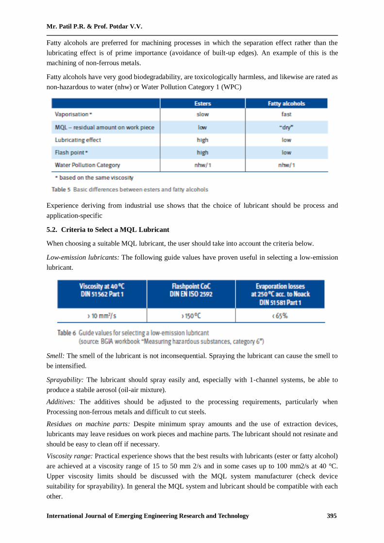
5.2. Criteria to Select a MQL Lubricant
When choosing a suitable MQL lubricant, the user should take into account the criteria below.
Low-emission lubricants: The following guide values have proven useful in selecting a low-emission
lubricant.
Smell: The smell of the lubricant is not inconsequential. Spraying the lubricant can cause the smell to
be intensified.
Sprayability: The lubricant should spray easily and, especially with 1-channel systems, be able to
produce a stabile aerosol (oil-air mixture).
Additives: The additives should be adjusted to the processing requirements, particularly when
Processing non-ferrous metals and difficult to cut steels.
Residues on machine parts: Despite minimum spray amounts and the use of extraction devices,
lubricants may leave residues on work pieces and machine parts. The lubricant should not resinate and
should be easy to clean off if necessary.
Viscosity range: Practical experience shows that the best results with lubricants (ester or fatty alcohol)
are achieved at a viscosity range of 15 to 50 mm 2/s and in some cases up to 100 mm2/s at 40 °C.
Upper viscosity limits should be discussed with the MQL system manufacturer (check device
suitability for sprayability). In general the MQL system and lubricant should be compatible with each
other.

Minimum Quantity Lubrication with Timer Based Control in Machning of EN9 Material
International Journal of Emerging Engineering Research and Technology 396
Lubricant change: Before a new lubricant is used, the system should be completely drained and
flushed. The flushing process should be performed with the new lubricant.
Corrosion protection: A check should be made as to whether the thin MQL residual film on the work-
piece after machining offers corrosion protection that meets the requirements or whether additional
corrosion protection is necessary.
Unsuitable lubricants for minimum quantity lubrication
The following products have proven not to be suitable for minimum quantity lubrication and should
therefore not be used:
Natural oils and greases: Esters (rape seed oil, etc.) have the disadvantage that they are very prone to
oxidation. They tend to gum up machine elements.
Water-miscible metalworking fluids and their concentrates: These products may contain biocides and
thus can be found in the spray aerosols.
Lubricants with additives containing organic chlorine or zinc: Due to high process-related machining
temperatures encountered when using Minimum quantity lubrication, reaction products harmful to
health may result.
Lubricants with mandatory marking: (Orange hazard symbol in compliance with the hazardous
substances ordinance).These products have a hazard potential level that is already high.
Mineral oil-based products with high aromatic compound content: (> 3 ppm benzo[a]pyrene in the
metalworking fluid)
Polycyclic aromatic compounds have a carcinogenic potential: More information on the topic of
lubricants for minimum quantity lubrication can be found in the BGIA workbook ―Measuring
hazardous substances, category 6‖.
6. DESIGN
Design consists of application of scientific principles, technical information and imagination for
development of new or improvised machine or mechanism to perform a specific function with
maximum economy & efficiency.
Hence a careful design approach has to be adopted. The total design work , has been split up into two
parts
System design
Mechanical Design.
System design mainly concerns the various physical constraints and ergonomics, space requirements,
arrangement of various components on main frame at system, man + machine interactions, No. of
controls, position of controls, working environment of machine, chances of failure, safety measures to
be provided, servicing aids, ease of maintenance, scope of improvement, weight of machine from
ground level, total weight of machine and a lot more.
In mechanical design the components are listed down and stored on the basis of their procurement,
design in two categories namely,
Designed Parts
Parts to be purchased

Mr. Patil P.R. & Prof. Potdar V.V.
International Journal of Emerging Engineering Research and Technology 397
For designed parts detached design is done & distinctions thus obtained are compared to next highest
dimensions which is readily available in market. This amplifies the assembly as well as
postproduction servicing work. The various tolerances on the works are specified. The process charts
are prepared and passed on to the manufacturing stage
The parts which are to be purchased directly are selected from various catalogues & specified so that
any body can purchase the same from the retail shop with given specifications.
7. SYSTEM DESIGN
In system design we mainly concentrated on the following parameters:
1. System Selection Based on Physical Constraints
While selecting any machine it must be checked whether it is going to be used in a large-scale
industry or a small-scale industry. In our case it is to be used by a small-scale industry. So space is a
major constrain. The system is to be very compact so that it can be adjusted to corner of a room.
The mechanical design has direct norms with the system design. Hence the foremost job is to control
the physical parameters, so that the distinctions obtained after mechanical design can be well fitted
into that.
2. Arrangement of Various Components
Keeping into view the space restrictions the components should be laid such that their easy removal or
servicing is possible. More over every component should be easily seen none should be hidden.
Every possible space is utilized in component arrangements.
3. Components of System
As already stated the system should be compact enough so that it can be accommodated at a corner of
a room. All the moving parts should be well closed & compact. A compact system design gives a
high weighted structure which is desired.
4. Man Machine Interaction
The friendliness of a machine with the operator that is operating is an important criteria of design. It is
the application of anatomical & psychological principles to solve problems arising from Man –
Machine relationship. Following are some of the topics included in this section.
Design of hand lever
Energy expenditure in foot & hand operation
Lighting condition of machine.
5. Chances of Failure
The losses incurred by owner in case of any failure is an important criteria of design. Factor safety
while doing mechanical design is kept high so that there are less chances of failure. Moreover
periodic maintenance is required to keep unit healthy.
6. Servicing Facility
The layout of components should be such that easy servicing is possible. Especially those
components which require frequents servicing can be easily disassembled.
7. Scope of Future Improvement
Arrangement should be provided to expand the scope of work in future. Such as to convert the
machine motor operated; the system can be easily configured to required one. The die & punch can
be changed if required for other shapes of notches etc.
Minimum Quantity Lubrication with Timer Based Control in Machning of EN9 Material
International Journal of Emerging Engineering Research and Technology 398
8. Height of Machine from Ground
For ease and comfort of operator the height of machine should be properly decided so that he may not
get tired during operation. The machine should be slightly higher than the waist level, also enough
clearance should be provided from the ground for cleaning purpose.
9. Weight of Machine
The total weight depends upon the selection of material components as well as the dimension of
components. A higher weighted machine is difficult in transportation & in case of major breakdown,
it is difficult to take it to workshop because of more weight.
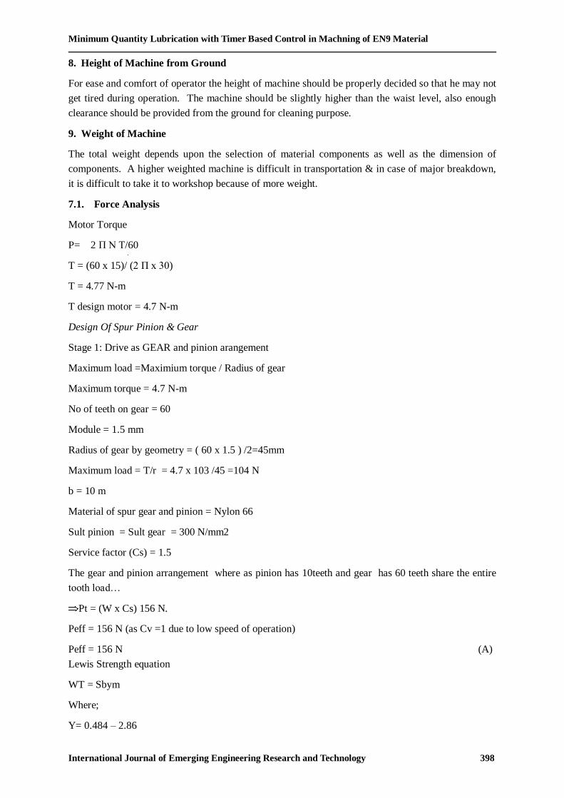
7.1. Force Analysis
Motor Torque
P= 2 П N T/60
T = (60 x 15)/ (2 П x 30)
T = 4.77 N-m
T design motor = 4.7 N-m
Design Of Spur Pinion & Gear
Stage 1: Drive as GEAR and pinion arangement
Maximum load =Maximium torque / Radius of gear
Maximum torque = 4.7 N-m
No of teeth on gear = 60
Module = 1.5 mm
Radius of gear by geometry = ( 60 x 1.5 ) /2=45mm
Maximum load = T/r = 4.7 x 10³ /45 =104 N
b = 10 m
Material of spur gear and pinion = Nylon 66
Sult pinion = Sult gear = 300 N/mm2
Service factor (Cs) = 1.5
The gear and pinion arrangement where as pinion has 10teeth and gear has 60 teeth share the entire
tooth load…
Pt = (W x Cs) 156 N.
Peff = 156 N (as Cv =1 due to low speed of operation)
Peff = 156 N (A)
Lewis Strength equation
WT = Sbym
Where;
Y= 0.484 – 2.86

Mr. Patil P.R. & Prof. Potdar V.V.
International Journal of Emerging Engineering Research and Technology 399
Z yp = 0.484 - 2.86/10= 0.198
yg = 0.484 – 2.86/60= 0.436
Syp = 59.4
Syg = 130.8
As Syp < Sys pinion is weaker
WT = (Syp ) x b x m
=59.4 x 10m x m
WT= 594m2 (B)
Equation (A) & (B)
594 m2 = 156
m=51 mm
Selecting standard module = 1.5 mm ----for ease of construction as we go for single stage gear
box…making size compact …achieving maximum strength and proper mesh.
Hence gear pair dimensions are as follows,
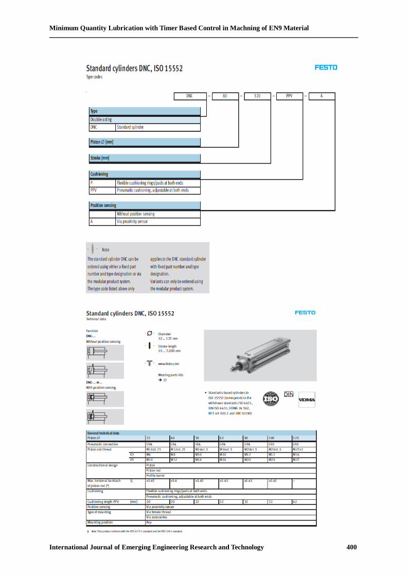
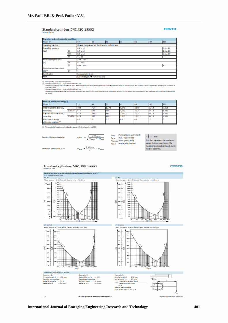
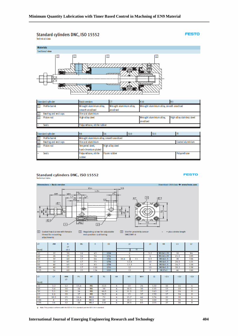
Selection of Cylinder
STANDARD CATALOGUE IS NOT AVAILABLE SEPERATELY FOR CYLINDER THAT WE
USE, Ie, 50 mm piston dia and 40 mm stroke… the data below is standard sheet as example to
ordering code and cylinder details…….
Minimum Quantity Lubrication with Timer Based Control in Machning of EN9 Material
International Journal of Emerging Engineering Research and Technology 400
Mr. Patil P.R. & Prof. Potdar V.V.
International Journal of Emerging Engineering Research and Technology 401

Minimum Quantity Lubrication with Timer Based Control in Machning of EN9 Material
International Journal of Emerging Engineering Research and Technology 402

International Journal of Emerging Engineering Research and Technology
Volume 2, Issue 4, July 2014, PP 392-410
ISSN 2349-4395 (Print) & ISSN 2349-4409 (Online)
©IJEERT www.ijeert.org 403
Minimum Quantity Lubrication with Timer Based Control in Machning of EN9 Material
International Journal of Emerging Engineering Research and Technology 404
Mr. Patil P.R. & Prof. Potdar V.V.
International Journal of Emerging Engineering Research and Technology 405
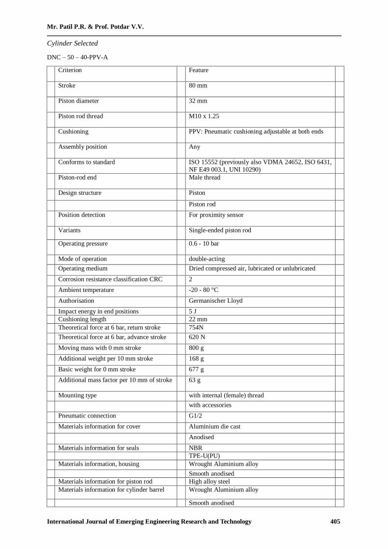
Cylinder Selected
DNC – 50 – 40-PPV-A
Criterion Feature
Stroke 80 mm
Piston diameter 32 mm
Piston rod thread M10 x 1.25
Cushioning PPV: Pneumatic cushioning adjustable at both ends
Assembly position Any
Conforms to standard ISO 15552 (previously also VDMA 24652, ISO 6431,
NF E49 003.1, UNI 10290)
Piston-rod end Male thread
Design structure Piston
Piston rod
Position detection For proximity sensor
Variants Single-ended piston rod
Operating pressure 0.6 - 10 bar
Mode of operation double-acting
Operating medium Dried compressed air, lubricated or unlubricated
Corrosion resistance classification CRC 2
Ambient temperature -20 - 80 °C
Authorisation Germanischer Lloyd
Impact energy in end positions 5 J
Cushioning length 22 mm
Theoretical force at 6 bar, return stroke 754N
Theoretical force at 6 bar, advance stroke 620 N
Moving mass with 0 mm stroke 800 g
Additional weight per 10 mm stroke 168 g
Basic weight for 0 mm stroke 677 g
Additional mass factor per 10 mm of stroke 63 g
Mounting type with internal (female) thread
with accessories
Pneumatic connection G1/2
Materials information for cover Aluminium die cast
Anodised
Materials information for seals NBR
TPE-U(PU)
Materials information, housing Wrought Aluminium alloy
Smooth anodised
Materials information for piston rod High alloy steel
Materials information for cylinder barrel Wrought Aluminium alloy
Smooth anodised
Minimum Quantity Lubrication with Timer Based Control in Machning of EN9 Material
International Journal of Emerging Engineering Research and Technology 406
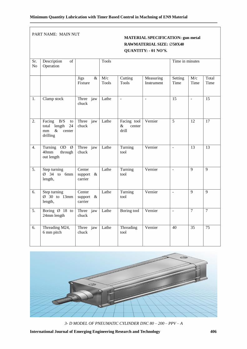
3- D MODEL OF PNEUMATIC CYLINDER DNC 80 – 200 – PPV – A
PART NAME: MAIN NUT
Sr.
No
Description of
Operation
Tools Time in minutes
Jigs &
Fixture
M/c
Tools
Cutting
Tools
Measuring
Instrument
Setting
Time
M/c
Time
Total
Time
1. Clamp stock Three jaw
chuck
Lathe - - 15 - 15
2. Facing B/S to
total length 24
mm & center
drilling
Three jaw
chuck
Lathe Facing tool
& center
drill
Vernier 5 12 17
4. Turning OD Ø
40mm through
out length
Three jaw
chuck
Lathe Turning
tool
Vernier - 13 13
5. Step turning
Ø 34 to 6mm
length,
Center
support &
carrier
Lathe Turning
tool
Vernier - 9 9
6. Step turning
Ø 30 to 13mm
length,
Center
support &
carrier
Lathe Turning
tool
Vernier - 9 9
5.
Boring Ø 18 to
24mm length
Three jaw
chuck
Lathe Boring tool Vernier - 7 7
6. Threading M24,
6 mm pitch
Three jaw
chuck
Lathe Threading
tool
Vernier 40 35 75
MATERIAL SPECIFICATION: gun metal
RAWMATERIAL SIZE: 50X40
QUANTITY: - 01 NO’S.
QUANTITY : 01 No’s
Mr. Patil P.R. & Prof. Potdar V.V.
International Journal of Emerging Engineering Research and Technology 407
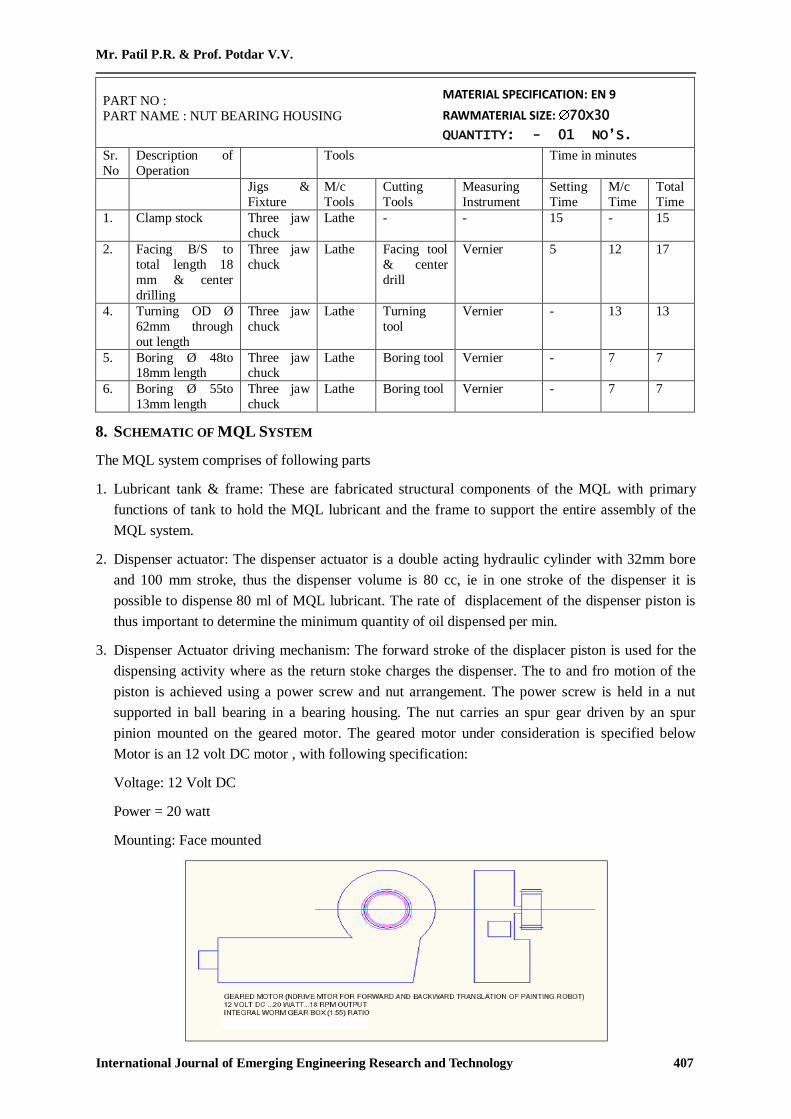
PART NO :
PART NAME : NUT BEARING HOUSING
Sr.
No
Description of
Operation
Tools Time in minutes
Jigs &
Fixture
M/c
Tools
Cutting
Tools
Measuring
Instrument
Setting
Time
M/c
Time
Total
Time
1. Clamp stock Three jaw
chuck
Lathe - - 15 - 15
2. Facing B/S to
total length 18
mm & center
drilling
Three jaw
chuck
Lathe Facing tool
& center
drill
Vernier 5 12 17
4. Turning OD Ø
62mm through
out length
Three jaw
chuck
Lathe Turning
tool
Vernier - 13 13
5.
Boring Ø 48to 18mm length
Three jaw chuck
Lathe Boring tool Vernier - 7 7
6. Boring Ø 55to
13mm length
Three jaw
chuck
Lathe Boring tool Vernier - 7 7
8. SCHEMATIC OF MQL SYSTEM
The MQL system comprises of following parts
1. Lubricant tank & frame: These are fabricated structural components of the MQL with primary
functions of tank to hold the MQL lubricant and the frame to support the entire assembly of the
MQL system.
2. Dispenser actuator: The dispenser actuator is a double acting hydraulic cylinder with 32mm bore
and 100 mm stroke, thus the dispenser volume is 80 cc, ie in one stroke of the dispenser it is
possible to dispense 80 ml of MQL lubricant. The rate of displacement of the dispenser piston is
thus important to determine the minimum quantity of oil dispensed per min.
3. Dispenser Actuator driving mechanism: The forward stroke of the displacer piston is used for the
dispensing activity where as the return stoke charges the dispenser. The to and fro motion of the
piston is achieved using a power screw and nut arrangement. The power screw is held in a nut
supported in ball bearing in a bearing housing. The nut carries an spur gear driven by an spur
pinion mounted on the geared motor. The geared motor under consideration is specified below
Motor is an 12 volt DC motor , with following specification:
Voltage: 12 Volt DC
Power = 20 watt
Mounting: Face mounted
MATERIAL SPECIFICATION: EN 9
RAWMATERIAL SIZE: 70X30
QUANTITY: - 01 NO’S.
QUANTITY : 01 No’s

Minimum Quantity Lubrication with Timer Based Control in Machning of EN9 Material
International Journal of Emerging Engineering Research and Technology 408
Motor rotates in clockwise and counter clockwise directions to effect the forward and reverse
motion of the screw and thereby the piston. Motor speed is regulated by speed regulator where as
the direction control is done using a direction control 2 pole -2 way switch
4. Inlet circuit to dispenser: The inlet circuit to the dispenser uses a non return valve opening into the
cylinder side and closing on the tank side. This allows lubricant flow from the lubricant tank to the
cylinder during suction stroke where as prevents reverse flow from the cylinder to tank during
dispensing stroke.
5. Dispensing Circuit: Dispensing circuit connects the outlet of cylinder to the mixing chamber. The
circuit comprises the an non return valve opening into the mixing chamber side and closing on the
cylinder side. This allows lubricant flow from the cylinder to mixing chamber during dispensing
stroke where as prevents reverse air flow from the mixing chamber to cylinder during suction
stroke. Circuit also has flow control valve for fine adjustments of flow rate of lubricant to mixing
chamber, and pressure gage indicates the pressure in the delivery line.
6. Mixing chamber : Mixing chamber is the device that mixes the MQL lubricant and the compressed
air to create lubricant mist to be directed onto the cutting action area to serve a three fold purpose ;
6.1. Lubricate the tool tip and job contact area during cutting to minimize the friction between
them, thereby reducing the heat produce. Misty nature of the lubricant ensure effective
application of lubricant and better heat extraction.
6.2. The second advantage of using compressed air mist that, it helps chip evacuation from the
cutting area which is one of the major reasons of development of ‗built-up-edges ‗on tool tip
leading to reduced tool life and improper surface finish on job.
6.3. The compressed air offer other advantage that , fumes that are likely to be developed due to
burning of the lubricant are not developed due to the high velocity of the lubricant particles
(they do not reach flash point).
7. Flex hose with interchangeable nozzle: The flex hose connects the mixing chamber and the nozzle,
two set of spray nozzle with tip diameters1.5 and 2.0 mm are provided for spraying.
9. WORKING
9.1. Dispenser Charging Cycle
Motor is rotated in clockwise direction that rotates the nut in counter clockwise direction due to spur
gearing , nut rotate and screw is constrained to translate hence it moves back thereby moving the
piston in backward direction thereby effecting the suction stroke. The inlet circuit to the dispenser
uses a non return valve opening into the cylinder side and closing on the tank side. This allows
lubricant flow from the lubricant tank to the cylinder during suction stroke where as prevents reverse
flow from the cylinder to tank during dispensing stroke.
9.2. Timer Based Dispenser Delivery Cycle
Timer based cycle will start at the programmed interval thereby discharging predetermined quantity of
lubricant into the mixing chamber. The timer controls the motion of the motor used in the dispensing
cycle Motor is rotated in counter-clockwise direction that rotates the nut in clockwise direction due to
spur gearing , nut rotates and screw is constrained to translate hence it moves forward thereby moving
the piston in forward direction thereby effecting the delivery stroke. Dispensing circuit connects the
outlet of cylinder to the mixing chamber. The circuit comprises the an non return valve opening into
the mixing chamber side and closing on the cylinder side. This allows lubricant flow from the
Mr. Patil P.R. & Prof. Potdar V.V.
International Journal of Emerging Engineering Research and Technology 409
cylinder to mixing chamber during dispensing stroke where as prevents reverse air flow from the
mixing chamber to cylinder during suction stroke. Circuit also has flow control valve for fine
adjustments of flow rate of lubricant to mixing chamber, and pressure gage indicates the pressure in
the delivery line.
MOTOR-The drive motor is 12 VDC motor coupled to an planetary gear box.
Specifications of motor are as follows:
A) Power 15 watt
B) Speed = 30 rpm
c) Gear box: Planetary /epicyclic type (reduction ratio: 1:5)
d) Mounting dimensions (Face mounted M12 x 1.5) pitch
10. RESULT & DISCUSSION
In convectional lubrication system having further drawbacks during turning like
1. chip formation.
2. heat generation.
3. tool wear.
4. surface finish and surface integrity. Hence to overcomes above disadvantages MQL system is
preferred, the reason behind it the advantages o MQL over convectional method.
10.1. Advantages
1. Lubricant wastage is minimized
2. Lubricant optimum utilization is possible
3. Chip-disposal is easy
4. Tool life is increased
5. Better surface finish is achieved.
6. Clean machine and machine environment.
10.2. Disadvantages
1. Intial infrastructure cost is high.
2. Maintenance cost is added.
3. Operator skill and intervention necessary.
11. FUTURE SCOPE
1. Time can be introduced for measured performance.
2. Microprocessor introduction can make computer control possible.
12. CONCLUSION
As per the analysis & result, the conclusion o this paper is MQL technique offer better surface finish
and dimensional accuracies than convectional lubrication in terms while machining the components.
Also improve in tool life & reduction in tool wear & heat generation.

Minimum Quantity Lubrication with Timer Based Control in Machning of EN9 Material
International Journal of Emerging Engineering Research and Technology 410
REFERENCES
[1] ACGIH, 2001. Documentation of the threshold limit values and biological exposure indices. 6th
edition, Cincinnati, American Conf. of Governmental Industrial Hygienist. ANSI, 1997. ANSI Technical Report B11 TR 21997.
[2] Dhar,N.R., Islam, S., 2005.Improvement in machinability characteristics and working
environment by minimum quantity lubrication. CASR Project, BUET, Unpublished Database.
[3] P. Leskover and J. Grum, The metallurgical aspect of machining, Annals of CIRP,35 (1): 537–
550 (1986).
[4] Tawakoli T, Hadad M J, Sadeghi M H, Daneshi A, Stöckert S and Rasifard A. An experimental
investigation of the effects of work piece and grinding parameters on minimum quantity
lubrication—MQL grinding. International Journal of Machine Tools and Manufacture. 2009; 49(12-13):924-932. http://dx.doi.org/10.1016/j.ijmachtools.2009.06.015.
[5] MaClure, T. F., Adams, R. and Gugger, M. D, Comparison of Flood vs.Microlubrication on Machining Performance, website: http://www.unist.com/techsolve.html, 2001.
[6] Aleksandar Filipovic and David A. Stephenson (2006), ―Minimum Quantity Lubrication (MQL):
Applications in Automotive Power-Train Machining‖, Machining Science and Technology, Vol.
10, pp: 3-22.